400g cwdm8 msa 2 km optical interface technical
TRANSCRIPT
400G CWDM8 MSA 2 km Technical Specifications Revision 11
400G CWDM8 MSA 2 km Technical Specifications Revision 11 1
400G CWDM8 MSA
2 km Optical Interface
Technical Specifications
Revision 11
February 13 2018
Contact cwdm8-msaorg
400G CWDM8 MSA 2 km Technical Specifications Revision 11
400G CWDM8 MSA 2 km Technical Specifications Revision 11 2
Table of Contents
1 General 5
11 Scope 5
12 Reference Documents 5
13 400G CWDM8 Transceiver Block Diagram 6
14 Functional Description 6
15 Hardware Signaling Pins 6
16 Optical Transceiver Management Interface 6
17 High Speed Electrical Characteristics 6
18 FEC Requirements 7
19 Mechanical Dimensions 7
110 Operating Environment 7
111 Power Supplies and Power Dissipation 7
2 CWDM8 Optical Specifications 8
21 Optical Wavelengths8
22 Optical Specifications 8
221 CWDM8 Transmitter Optical Specifications 8
222 CWDM8 Receiver Optical Specifications 9
223 CWDM8 2 km Interface Illustrative Link Power Budget 10
3 Definition of Optical Parameters and Measurement Methods 10
31 Test Patterns for Optical Parameters 10
311 Square Wave Pattern Definition 10
312 SSPR Pattern Definition 10
32 Skew and Skew Variation 11
33 Wavelength 11
34 Average Optical Power 11
35 Optical Modulation Amplitude (OMA) 11
36 Transmitter Dispersion and Eye Closure Penalty (TDEC) 11
400G CWDM8 MSA 2 km Technical Specifications Revision 11
400G CWDM8 MSA 2 km Technical Specifications Revision 11 3
361 TDEC Conformance Test Setup 11
362 Channel Requirements 12
363 TDEC Measurement Method 12
37 Extinction Ratio 13
38 Transmitter Optical Waveform (Transmit Eye) 13
39 Receiver Sensitivity 13
310 Stressed Receiver Sensitivity 14
4 Fiber Optic Cabling Model 14
5 Characteristics of the Fiber Optic Cabling (Channel) 15
51 Optical Fiber Cable 15
52 Optical Fiber Connection 15
521 Connection Insertion Loss 15
522 Maximum Discrete Reflectance 15
53 Medium Dependent Interface (MDI) Requirements 15
6 CWDM8 Optical Transceiver Color Coding 16
400G CWDM8 MSA 2 km Technical Specifications Revision 11
400G CWDM8 MSA 2 km Technical Specifications Revision 11 4
Participants Editor Karl Muth Rockley Photonics
Assistant Editor Scott Schube Intel
The following companies were members of the CWDM8 MSA at the time of the release of this document
Accton Applied Optoelectronics Barefoot Networks Credo Semiconductor Hisense Innovium Intel Keysight
MACOM Mellanox NeoPhotonics New H3C Technologies and Rockley Photonics
Revision History Revision Date Description
10 11172017 Initial release
11 01212018 Replaced PRBS31 pattern with SSPR changed golden PLL BW to 4 MHz removed SRS eye mask added comment for SEC in SRS testing added pull tab color
400G CWDM8 MSA 2 km Technical Specifications Revision 11
400G CWDM8 MSA 2 km Technical Specifications Revision 11 5
1 General The companies that prepared this version of the specification acknowledge the work of the IEEE 8023 standards
efforts and the CWDM4 MSA These CWDM8 Specifications are based on much of the work the IEEE standards
body has developed for 400G industry standards as well as the CWDM4 MSA This technical document has been
created with inputs from several companies This document is offered to transceiver users and suppliers as a
basis for discussion and comment However it is not a warranted document each transceiver supplier will have
their own datasheet If the user wishes to find a warranted document they should consult the datasheet of the
chosen transceiver supplier
11 Scope These technical specifications define an 8 x 50 Gbs Coarse Wavelength Division Multiplexing (CWDM)
optical interface for 400 Gbs optical transceivers for Ethernet applications including 400 Gigabit Ethernet
Two optical transceivers implementing this interface can communicate over single mode fibers (SMF) of
length from 2 meters up to 2 kilometers The transceiver electrical interface is not specified in this
document but can have for example 8 lanes in each direction with a nominal signaling rate of 53125 Gbs
per lane
Different form factors for the transceivers are possible Common implementations at the time of this
writing are expected to include QSFP-DD and OSFP pluggable optical transceivers as well as COBO on-board
optical transceivers Other form factors are possible and are not precluded by these specifications
12 Reference Documents IEEE 8023bs
IEEE Std 8023-2015
OIF-CEI-031 (httpwwwoiforumcom)
OIF-CEI-56G specification family (httpwwwoiforumcom)
QSFD-DD MSA (httpwwwqsfp-ddcom)
OSFP MSA (httposfpmsaorg)
400G CWDM8 MSA 2 km Technical Specifications Revision 11
400G CWDM8 MSA 2 km Technical Specifications Revision 11 6
13 400G CWDM8 Transceiver Block Diagram
WD = Wavelength division NOTE ndash Specification of the retimer function is beyond the scope of this MSA
Figure 1 Block diagram for 400G CWDM8 transmit and receive paths
14 Functional Description CWDM8 optical transceivers comply with the requirements of this document and have the following
common features eight optical transmitters eight optical receivers with signal detect wavelength division
multiplexer and demultiplexer and a duplex optical connector for single mode fiber The optical connector
type is vendor specific and not defined in these specifications but can include SC or LC types
15 Hardware Signaling Pins Hardware signaling pins are specified in the respective optical transceiver form factor MSAs
16 Optical Transceiver Management Interface The contents of the various ID registers in optical transceiver memory shall comply with the requirements of
the optical transceiver MSAs eg the QSFP-DD MSA or the OSFP MSA and the respective applicable
standards
17 High Speed Electrical Characteristics The detailed high speed electrical characteristics are not defined by these specifications and can be
implemented in compliance with the IEEE 400GAUI-8 interface OIF CEI-56G-VSR or other appropriate IEEE
OIF or other electrical interface standards
400G CWDM8 MSA 2 km Technical Specifications Revision 11
400G CWDM8 MSA 2 km Technical Specifications Revision 11 7
18 FEC Requirements The optical link is specified to operate at a bit error ratio (BER) of 2 x 10⁻⁴ To support this optical interface
specification the host system is required to enable 400G RS(544514) FEC in accordance with clause 119 of
IEEE 8023bs The option to bypass the Clause 119 RS-FEC correction function is not supported
19 Mechanical Dimensions Mechanical dimensions are defined in the optical module form factor MSA specifications
110 Operating Environment All specified minimum and maximum parameter values shall be met when the host system maintains the
operating case temperature and supply voltages within the optical module vendor specified operating
ranges All minimum and maximum limits apply over the operating life of the system
111 Power Supplies and Power Dissipation Optical transceiver vendors shall specify the optical module power supply requirements in accordance with
the optical module MSA
400G CWDM8 MSA 2 km Technical Specifications Revision 11
400G CWDM8 MSA 2 km Technical Specifications Revision 11 8
2 CWDM8 Optical Specifications
21 Optical Wavelengths The wavelength range for each lane of the 400G CWDM8 optical transceiver is defined in Table 1 The center
wavelengths are spaced at 20 nm
Table 1 Wavelength Range
Lane Center Wavelength Wavelength Range
L0 1271 nm 12645 to 12775 nm
L1 1291 nm 12845 to 12975 nm
L2 1311 nm 13045 to 13175 nm
L3 1331 nm 13245 to 13375 nm
L4 1351 nm 13445 to 13575 nm
L5 1371 nm 13645 to 13775 nm
L6 1391 nm 13845 to 13975 nm
L7 1411 nm 14045 to 14175 nm
22 Optical Specifications The operating range for a CWDM8 transceiver is defined in Table 2 A CWDM8 compliant PMD operates on
single-mode fibers according to the specifications defined in Table 8 and characteristics in Table 9 A PMD
that exceeds the required operating range while meeting all other optical specifications is considered
compliant (eg operating at 3 km meets the operating range requirement of 2 m to 2 km)
Table 2 Operating range
Module type Required operating range
400GE-CWDM8-2 2 m to 2 km
221 CWDM8 Transmitter Optical Specifications The 400G CWDM8 transmitter shall meet the specifications defined in Table 3
Table 3 400G CWDM8 transmit characteristics
Description Minimum Maximum Unit
Signaling rate each lane 53125 plusmn 100 ppm Gbd
Modulation format NRZ
Wavelengths
12645 12845 13045 13245 13445 13645 13845 14045
12775 12975 13175 13375 13575 13775 13975 14175
nm
Side mode suppression ratio (SMSR) 30 - dB
Total average launch power - 85 dBm
Average launch power each lanea -55 25 dBm
Optical modulation amplitude (OMA) each laneb -3 25 dBm
Launch power in OMA minus TDEC each lane -4 - dBm
Difference in launch power between any two lanes (average and OMA) - 4 dB
400G CWDM8 MSA 2 km Technical Specifications Revision 11
400G CWDM8 MSA 2 km Technical Specifications Revision 11 9
Transmitter dispersion and eye closure penalty (TDEC) each lane - 28 dB
Average launch power of OFF transmitter each lane - -30 dBm
Extinction ratio 35 - dB
Optical return loss tolerance - 171 dB
Transmitter reflectance(c) - -26 dB a The minimum requirement for average launch power each lane is informative and not the principal indicator of signal
strength A transmitter with launch power below this value cannot be compliant however a value above this does not
ensure compliance b Even if the TDEC lt 10 dB the minimum OMA must exceed the minimum OMA requirement c Transmitter reflectance is defined looking into the transmitter
222 CWDM8 Receiver Optical Specifications The CWDM4 receiver shall meet the specifications defined in Table 4
Table 4 400G CWDM8 receive characteristics
Description Minimum Maximum Unit
Signaling rate each lane 53125 plusmn 100 ppm Gbd
Wavelengths
12645 12845 13045 13245 13445 13645 13845 14045
12775 12975 13175 13375 13575 13775 13975 14175
nm
Damage threshold each lanea 35 - dBm
Average receive power each laneb -95 25 dBm
Receive power in OMA each lane - 25 dBm
Receiver reflectance - -26 dB
Receiver sensitivity (OMA) each lane at 2 x 10⁻⁴ BERc - -8 dBm
Stressed receiver sensitivity (OMA) each laned - -53 dBm
Conditions of stressed receiver sensitivity test
Stressed eye closure (SEC) each lanee 27 dB
Stressed eye J2 jitter each lanee 033 UI
Stressed eye J4 jitter each lanee 048 UI a The receiver shall be able to tolerate without damage continuous exposure to a signal having this average power level b The minimum requirement for average receive power each lane is informative and not the principal indicator of signal strength A
received power below this value cannot be compliant however a value above this does not ensure compliance c Receiver sensitivity (OMA) each lane is a normative specification d Measured with conformance test signal at TP3 (see 310) for BER = 2 x 10⁻⁴ e Stressed eye closure stressed eye J2 jitter and stressed eye J4 jitter are test conditions for measuring stressed receiver sensitivity
They are not characteristics of the receiver
400G CWDM8 MSA 2 km Technical Specifications Revision 11
400G CWDM8 MSA 2 km Technical Specifications Revision 11 10
223 CWDM8 2 km Interface Illustrative Link Power Budget An illustrative power budget and penalties for CWDM4 are shown in Table 5
Table 5 400G CWDM8 illustrative power budget
Description Value Unit
Power budget (for max TDEC) 68 dB
Operating distance 2 km
Channel insertion loss(a) 4 dB
Maximum discrete reflectance(b) -35 dB
Allocation for penalties (for max TDEC) 28 dB
Additional insertion loss allowed 0 dB
(a) Includes 01dB MPI penalty (b) Assumes 6 connectors in the link
3 Definition of Optical Parameters and Measurement Methods
31 Test Patterns for Optical Parameters All optical measurements shall be made through a short patch cable between 2 m and 5 m in length unless
otherwise specified
Table 6 Patterns for optical parameter testing
Parameter Pattern
Wavelength SSPR
Side mode suppression ratio SSPR
Average optical power SSPR
Optical modulation amplitude (OMA) Square wave
Transmitter dispersion and eye closure penalty (TDEC)(a) SSPR
Extinction ratio SSPR
Transmitter optical waveform SSPR
Stressed receiver sensitivity SSPR
Calibration of OMA for receiver tests PRBS9
Stressed eye closure calibration SSPR
(a) Or RS-FEC encoded scrambled idle according to IEEE8023bs Clause 119
311 Square Wave Pattern Definition A pattern consisting of eight ones followed by an equal run of zeroes may be used as a square wave
312 SSPR Pattern Definition The SSPR pattern is defined as
Total length 32762 bits
All 2^28-1 PRBS28 sequences are generated using taps 25 and 28
Block 1 is 5437 bits of PRBS28 seed=0x0080080 and begins with 8x0111x0112x0 1
Block2 is 1 followed by 72x0
400G CWDM8 MSA 2 km Technical Specifications Revision 11
400G CWDM8 MSA 2 km Technical Specifications Revision 11 11
Block 3 is 5437 bits of PRBS28 seed=0xFFFFFFFF and begins 28x125x03x122x0
Block 4 takes the same sequence as block 1 (omitting the last 3 bits) and codes it - A zero is encoded as a change of output - A one is encoded as no change of output - The output before the first bit is assumed to have been a 0 - This block begins 1010101001010101010110101010101011011010
Blocks 5 to 8 are the inverse of 1 to 4 Under some circumstances (eg to accommodate the restrictions of some pieces of test equipment) it may be desirable to modify this short pattern to have a total length of 32768 bits (2^15) rather than 32762 bits To make use of this option the differentially encoded blocks (blocks 4 and 8) should be extended by 3 bits making these blocks 5437 bits long
32 Skew and Skew Variation Refer to IEEE Std 8023bs Clause 1223 CWDM8 MSA transceivers shall comply with the skew and skew
variation limits of IEEE Std 8023bs clause 12231 and 12232
33 Wavelength Measure per TIAEIA-455-127-A or IEC 61280-1-3
34 Average Optical Power Measure using the methods given in IEC 61280-1-1 with channels not being measured turned off
35 Optical Modulation Amplitude (OMA) Refer to IEEE Std 8023-2015 Clause 5295 OMA is measured with a square wave (8 ones 8 zeroes) test
pattern Each lane may be tested individually with all other lanes turned off or by using an optical filter if
the other lanes are active
36 Transmitter Dispersion and Eye Closure Penalty (TDEC) TDEC shall be as defined in IEEE Std 8023-2015 Clause 9585 with the exceptions that
- The optical to electrical converter bandwidth shall not include the optical channel which shall be
included explicitly as shown in 361 below
- Each optical lane is tested individually using an optical filter to separate the lane under test from the
others The optical filter pass band ripple shall be limited to 05 dB peak-to-peak and the isolation is
chosen such that the ratio of the power in the lane being measured to the sum of the powers of all the
other lanes is greater than 20 dB (see ITU-T G9591 Annex B) The lanes not under test shall be
operating with the test patterns mentioned in 31
361 TDEC Conformance Test Setup A block diagram for the TDEC conformance test is shown in Figure 2 Other measurement
implementations may be used with suitable calibration
400G CWDM8 MSA 2 km Technical Specifications Revision 11
400G CWDM8 MSA 2 km Technical Specifications Revision 11 12
Figure 2 TDEC conformance test setup
Each optical lane is tested individually with all other lanes in operation The optical splitter and variable
reflector are adjusted so that each transmitter is tested with an optical return loss of 171 dB
The combination of the OE and the oscilloscope used to measure the optical waveform has a fourth-
order Bessel-Thomson filter response with a bandwidth of 398 GHz Compensation may be made for
any deviation from an ideal fourth-order Bessel-Thomson response
The clock recovery unit (CRU) has a corner frequency of 4 MHz and a slope of 20 dBdecade
Two tests need to be performed with and without a fiber of 2km length specified in Table 7 The
maximum of the single discrete reflections of the inserted fiber are specified in Table 5 The transmitter
needs to pass both tests with a TDEC specified in Table 3
362 Channel Requirements The transmitter is tested using an optical channel that meets the requirements listed in Table 7
Table 7 Channel Requirements for TDEC Test
Type Dispersion (psnm)a Insertion lossb Optical return lossc
Minimum Maximum
CWDM8 00465λ[1-(1324 λ)4] 00465λ[1-(1300 λ)4] Minimum 171 dB
a The dispersion is measured for the wavelength of the device under test (λ in nm) The coefficient assumes 2 km for CWDM8 b There is no intent to stress the sensitivity of the BERTrsquos optical receiver c The optical return loss is applied at TP2 ie after a 2 meter patch cord
363 TDEC Measurement Method The TDEC measurement method shall follow IEEE Std 8023-2015 Clause 95852 with the following
exceptions
- The four vertical histograms are measured through the eye diagram are centered at 045 UI and 055
UI
- The BER is 24 x 10-4
- The Q factor is 34917
- The formula for the received noise R is
R = radic1198732 + 1198782
400G CWDM8 MSA 2 km Technical Specifications Revision 11
400G CWDM8 MSA 2 km Technical Specifications Revision 11 13
where as in Clause 95852 N represents the lesser of the left and right standard deviations σL and
σR and S is the standard deviation of the noise of the OE and oscilloscope combination Please
refer to the source material for a more detailed description of the calculations
37 Extinction Ratio Extinction ratio is measured using the methods specified in IEC 61280-2-2 with the lanes not under test
turned off
38 Transmitter Optical Waveform (Transmit Eye) Refer to IEEE Std 8023-2012 Clause 8888 with the following exceptions
- The clock recovery unitrsquos high-frequency corner bandwidth is 4 MHz
- The filter nominal reference frequency fr is 398 GHz and the filter tolerances are as specified for STM-64
in ITU-T G691
39 Receiver Sensitivity The nominal sensitivity of each receiver lane is measured in OMA using the setup of Figure 3 The sensitivity must be corrected for any significant reference transmitter impairments including any vertical eye closure It should be measured at the eye center or corrected for off- center sampling The reference transmitter wavelength(s) shall comply with the ranges in Table 4 The reference transmitter is a high-quality instrument grade device which can be implemented by a CW laser modulated by a high-performance modulator It should have the following basic requirements - The risefall times should be less than 6 ps at 20 to 80 - The output optical eye is symmetric and passes the transmitter optical waveform test of 38 - In the center 10 region of the eye the worst-case vertical eye closure penalty as defined in IEEE 8023-
2015 878112 is less than 05 dB - Total jitter less than 02 UI peak-to-peak - RIN of less than -140 dBHz Center of the eye is defined as the time halfway between the left and right sampling points within the eye
where the measured BER is greater than or equal to 24 x 10-4
The clock recovery unit (CRU) used in the sensitivity measurement has a corner frequency of less than or
equal to 4 MHz and a slope of 20 dBdecade When using a clock recovery unit as a clock for BER
measurement passing of low frequency jitter from the data to the clock removes this low-frequency jitter
from the measurement
Figure 3 Test setup for receiver sensitivity
400G CWDM8 MSA 2 km Technical Specifications Revision 11
400G CWDM8 MSA 2 km Technical Specifications Revision 11 14
310 Stressed Receiver Sensitivity Refer to IEEE Std 8023-2015 Cl 9588 with the following exceptions - The test BER is 2 x 10⁻⁴ - The stressed input signal shall be adjusted to provide the stressed eye closure and jitter defined in Table
4 above - Each lane is tested individually with all other Rx and Tx channels turned ON and receiving or transmitting
SSPR signals The maximum OMA difference between the Rx lane under test and the other Rx lanes not under test is 4 dB
- The fourth-order Bessel-Thomson filter has a 3 dB bandwidth of approximately 39 GHz - At least 20 dB of SEC (stressed eye closure) should be created by the selection of the appropriate band-
width for the combination of the low-pass filter and the EO converter
4 Fiber Optic Cabling Model
Figure 4 Fiber optic cabling model
The channel insertion loss is given in Table 8 A channel may contain additional connectors as long as the
optical characteristics of the channel such as attenuation dispersion reflections and polarization mode
dispersion meet the specifications Insertion loss measurements of installed fiber cables are made in
accordance with IEC 61280-4-2 using the one-cord reference method The fiber optic cabling model
(channel) defined here is the same as a simplex fiber optic link segment The term channel is used here for
consistency with generic cabling standards
Table 8 Fiber optic cabling (channel) characteristics
Description CWDM8 Unit
Operating distance 2 km
Channel insertion loss max(ab) 4 dB
Channel insertion loss min 0 dB
Positive dispersion(b) (max) 193 psnm
Negative dispersion(b) (min) -119 psnm
DGD_max(c) 3 ps
Optical return loss (min) 21 dB
(a) These channel loss values include cable connectors and splices (b) Over the wavelength range 12645 to 14175 nm (c) Differential Group Delay (DGD) is the time difference at reception between the fractions of a
pulse that were transmitted in the two principal states of polarization of an optical signal DGD_max is the maximum differential group delay that the system must tolerate
400G CWDM8 MSA 2 km Technical Specifications Revision 11
400G CWDM8 MSA 2 km Technical Specifications Revision 11 15
5 Characteristics of the Fiber Optic Cabling (Channel)
51 Optical Fiber Cable The fiber optic cable requirements are satisfied by cables containing
- IEC 60793-2-50 type B13 single mode fiber or equivalently ITU-T G652 types C and D (low water peak
single mode fiber) or
- IEC 60793-2-50 type B6_a1 and B6_a2 single mode fiber or equivalently ITU-T G657 types A1 and A2
(bend insensitive single mode fiber with low water peak)
Table 9 Fiber characteristics
Description Value Unit
Nominal fiber specification wavelength 1310 nm
Cabled optical fiber attenuation (max) 05a dBkm
Zero dispersion wavelength (λ0) 1300 le λ0 le 1324 nm
Dispersion slope (max) (S0) 0093 psnm2km
a The 05 dBkm attenuation is provided for Outside Plant cable as defined in ANSITIA 568-C3
52 Optical Fiber Connection An optical fiber connection as shown in Figure 4 consists of a mated pair of optical connectors
521 Connection Insertion Loss The maximum link distances for single-mode fiber are calculated based on an allocation of 3 dB total
connection and splice loss For example this allocation supports 6 connections with an average
insertion loss per connection of 05 dB Connections with different loss characteristics may be used
provided the requirements of Table 8 are met
522 Maximum Discrete Reflectance The maximum discrete reflectance shall be less than -35 dB
53 Medium Dependent Interface (MDI) Requirements The PMD is coupled to the fiber optic cabling at the MDI The MDI is the interface between the PMD and the ldquofiber optic cablingrdquo (as shown in Figure 4) Examples of an MDI include the following
a Connectorized fiber pigtail b PMD receptacle
When the MDI is a connector plug and receptacle connection it shall meet the interface performance specifications of IEC 61753-1-1 and IEC 61753-021-2
Note Transmitter compliance testing is performed at TP2 ie after a 2 meter patch cord not at the MDI
400G CWDM8 MSA 2 km Technical Specifications Revision 11
400G CWDM8 MSA 2 km Technical Specifications Revision 11 16
6 CWDM8 Optical Transceiver Color Coding Transceiver modules compliant to the CWDM8 MSA Specifications use a color code to indicate the application This color code can be on a transceiver module bail latch pull tab or other visible feature of the module when installed in a system The color code scheme is specified below
Color Code Application
Turquoise Pantone 3242U 400 Gbs CWDM8 2km reach
400G CWDM8 MSA 2 km Technical Specifications Revision 11
400G CWDM8 MSA 2 km Technical Specifications Revision 11 4
Participants Editor Karl Muth Rockley Photonics
Assistant Editor Scott Schube Intel
The following companies were members of the CWDM8 MSA at the time of the release of this document
Accton Applied Optoelectronics Barefoot Networks Credo Semiconductor Hisense Innovium Intel Keysight
MACOM Mellanox NeoPhotonics New H3C Technologies and Rockley Photonics
Revision History Revision Date Description
10 11172017 Initial release
11 01212018 Replaced PRBS31 pattern with SSPR changed golden PLL BW to 4 MHz removed SRS eye mask added comment for SEC in SRS testing added pull tab color
400G CWDM8 MSA 2 km Technical Specifications Revision 11
400G CWDM8 MSA 2 km Technical Specifications Revision 11 5
1 General The companies that prepared this version of the specification acknowledge the work of the IEEE 8023 standards
efforts and the CWDM4 MSA These CWDM8 Specifications are based on much of the work the IEEE standards
body has developed for 400G industry standards as well as the CWDM4 MSA This technical document has been
created with inputs from several companies This document is offered to transceiver users and suppliers as a
basis for discussion and comment However it is not a warranted document each transceiver supplier will have
their own datasheet If the user wishes to find a warranted document they should consult the datasheet of the
chosen transceiver supplier
11 Scope These technical specifications define an 8 x 50 Gbs Coarse Wavelength Division Multiplexing (CWDM)
optical interface for 400 Gbs optical transceivers for Ethernet applications including 400 Gigabit Ethernet
Two optical transceivers implementing this interface can communicate over single mode fibers (SMF) of
length from 2 meters up to 2 kilometers The transceiver electrical interface is not specified in this
document but can have for example 8 lanes in each direction with a nominal signaling rate of 53125 Gbs
per lane
Different form factors for the transceivers are possible Common implementations at the time of this
writing are expected to include QSFP-DD and OSFP pluggable optical transceivers as well as COBO on-board
optical transceivers Other form factors are possible and are not precluded by these specifications
12 Reference Documents IEEE 8023bs
IEEE Std 8023-2015
OIF-CEI-031 (httpwwwoiforumcom)
OIF-CEI-56G specification family (httpwwwoiforumcom)
QSFD-DD MSA (httpwwwqsfp-ddcom)
OSFP MSA (httposfpmsaorg)
400G CWDM8 MSA 2 km Technical Specifications Revision 11
400G CWDM8 MSA 2 km Technical Specifications Revision 11 6
13 400G CWDM8 Transceiver Block Diagram
WD = Wavelength division NOTE ndash Specification of the retimer function is beyond the scope of this MSA
Figure 1 Block diagram for 400G CWDM8 transmit and receive paths
14 Functional Description CWDM8 optical transceivers comply with the requirements of this document and have the following
common features eight optical transmitters eight optical receivers with signal detect wavelength division
multiplexer and demultiplexer and a duplex optical connector for single mode fiber The optical connector
type is vendor specific and not defined in these specifications but can include SC or LC types
15 Hardware Signaling Pins Hardware signaling pins are specified in the respective optical transceiver form factor MSAs
16 Optical Transceiver Management Interface The contents of the various ID registers in optical transceiver memory shall comply with the requirements of
the optical transceiver MSAs eg the QSFP-DD MSA or the OSFP MSA and the respective applicable
standards
17 High Speed Electrical Characteristics The detailed high speed electrical characteristics are not defined by these specifications and can be
implemented in compliance with the IEEE 400GAUI-8 interface OIF CEI-56G-VSR or other appropriate IEEE
OIF or other electrical interface standards
400G CWDM8 MSA 2 km Technical Specifications Revision 11
400G CWDM8 MSA 2 km Technical Specifications Revision 11 7
18 FEC Requirements The optical link is specified to operate at a bit error ratio (BER) of 2 x 10⁻⁴ To support this optical interface
specification the host system is required to enable 400G RS(544514) FEC in accordance with clause 119 of
IEEE 8023bs The option to bypass the Clause 119 RS-FEC correction function is not supported
19 Mechanical Dimensions Mechanical dimensions are defined in the optical module form factor MSA specifications
110 Operating Environment All specified minimum and maximum parameter values shall be met when the host system maintains the
operating case temperature and supply voltages within the optical module vendor specified operating
ranges All minimum and maximum limits apply over the operating life of the system
111 Power Supplies and Power Dissipation Optical transceiver vendors shall specify the optical module power supply requirements in accordance with
the optical module MSA
400G CWDM8 MSA 2 km Technical Specifications Revision 11
400G CWDM8 MSA 2 km Technical Specifications Revision 11 8
2 CWDM8 Optical Specifications
21 Optical Wavelengths The wavelength range for each lane of the 400G CWDM8 optical transceiver is defined in Table 1 The center
wavelengths are spaced at 20 nm
Table 1 Wavelength Range
Lane Center Wavelength Wavelength Range
L0 1271 nm 12645 to 12775 nm
L1 1291 nm 12845 to 12975 nm
L2 1311 nm 13045 to 13175 nm
L3 1331 nm 13245 to 13375 nm
L4 1351 nm 13445 to 13575 nm
L5 1371 nm 13645 to 13775 nm
L6 1391 nm 13845 to 13975 nm
L7 1411 nm 14045 to 14175 nm
22 Optical Specifications The operating range for a CWDM8 transceiver is defined in Table 2 A CWDM8 compliant PMD operates on
single-mode fibers according to the specifications defined in Table 8 and characteristics in Table 9 A PMD
that exceeds the required operating range while meeting all other optical specifications is considered
compliant (eg operating at 3 km meets the operating range requirement of 2 m to 2 km)
Table 2 Operating range
Module type Required operating range
400GE-CWDM8-2 2 m to 2 km
221 CWDM8 Transmitter Optical Specifications The 400G CWDM8 transmitter shall meet the specifications defined in Table 3
Table 3 400G CWDM8 transmit characteristics
Description Minimum Maximum Unit
Signaling rate each lane 53125 plusmn 100 ppm Gbd
Modulation format NRZ
Wavelengths
12645 12845 13045 13245 13445 13645 13845 14045
12775 12975 13175 13375 13575 13775 13975 14175
nm
Side mode suppression ratio (SMSR) 30 - dB
Total average launch power - 85 dBm
Average launch power each lanea -55 25 dBm
Optical modulation amplitude (OMA) each laneb -3 25 dBm
Launch power in OMA minus TDEC each lane -4 - dBm
Difference in launch power between any two lanes (average and OMA) - 4 dB
400G CWDM8 MSA 2 km Technical Specifications Revision 11
400G CWDM8 MSA 2 km Technical Specifications Revision 11 9
Transmitter dispersion and eye closure penalty (TDEC) each lane - 28 dB
Average launch power of OFF transmitter each lane - -30 dBm
Extinction ratio 35 - dB
Optical return loss tolerance - 171 dB
Transmitter reflectance(c) - -26 dB a The minimum requirement for average launch power each lane is informative and not the principal indicator of signal
strength A transmitter with launch power below this value cannot be compliant however a value above this does not
ensure compliance b Even if the TDEC lt 10 dB the minimum OMA must exceed the minimum OMA requirement c Transmitter reflectance is defined looking into the transmitter
222 CWDM8 Receiver Optical Specifications The CWDM4 receiver shall meet the specifications defined in Table 4
Table 4 400G CWDM8 receive characteristics
Description Minimum Maximum Unit
Signaling rate each lane 53125 plusmn 100 ppm Gbd
Wavelengths
12645 12845 13045 13245 13445 13645 13845 14045
12775 12975 13175 13375 13575 13775 13975 14175
nm
Damage threshold each lanea 35 - dBm
Average receive power each laneb -95 25 dBm
Receive power in OMA each lane - 25 dBm
Receiver reflectance - -26 dB
Receiver sensitivity (OMA) each lane at 2 x 10⁻⁴ BERc - -8 dBm
Stressed receiver sensitivity (OMA) each laned - -53 dBm
Conditions of stressed receiver sensitivity test
Stressed eye closure (SEC) each lanee 27 dB
Stressed eye J2 jitter each lanee 033 UI
Stressed eye J4 jitter each lanee 048 UI a The receiver shall be able to tolerate without damage continuous exposure to a signal having this average power level b The minimum requirement for average receive power each lane is informative and not the principal indicator of signal strength A
received power below this value cannot be compliant however a value above this does not ensure compliance c Receiver sensitivity (OMA) each lane is a normative specification d Measured with conformance test signal at TP3 (see 310) for BER = 2 x 10⁻⁴ e Stressed eye closure stressed eye J2 jitter and stressed eye J4 jitter are test conditions for measuring stressed receiver sensitivity
They are not characteristics of the receiver
400G CWDM8 MSA 2 km Technical Specifications Revision 11
400G CWDM8 MSA 2 km Technical Specifications Revision 11 10
223 CWDM8 2 km Interface Illustrative Link Power Budget An illustrative power budget and penalties for CWDM4 are shown in Table 5
Table 5 400G CWDM8 illustrative power budget
Description Value Unit
Power budget (for max TDEC) 68 dB
Operating distance 2 km
Channel insertion loss(a) 4 dB
Maximum discrete reflectance(b) -35 dB
Allocation for penalties (for max TDEC) 28 dB
Additional insertion loss allowed 0 dB
(a) Includes 01dB MPI penalty (b) Assumes 6 connectors in the link
3 Definition of Optical Parameters and Measurement Methods
31 Test Patterns for Optical Parameters All optical measurements shall be made through a short patch cable between 2 m and 5 m in length unless
otherwise specified
Table 6 Patterns for optical parameter testing
Parameter Pattern
Wavelength SSPR
Side mode suppression ratio SSPR
Average optical power SSPR
Optical modulation amplitude (OMA) Square wave
Transmitter dispersion and eye closure penalty (TDEC)(a) SSPR
Extinction ratio SSPR
Transmitter optical waveform SSPR
Stressed receiver sensitivity SSPR
Calibration of OMA for receiver tests PRBS9
Stressed eye closure calibration SSPR
(a) Or RS-FEC encoded scrambled idle according to IEEE8023bs Clause 119
311 Square Wave Pattern Definition A pattern consisting of eight ones followed by an equal run of zeroes may be used as a square wave
312 SSPR Pattern Definition The SSPR pattern is defined as
Total length 32762 bits
All 2^28-1 PRBS28 sequences are generated using taps 25 and 28
Block 1 is 5437 bits of PRBS28 seed=0x0080080 and begins with 8x0111x0112x0 1
Block2 is 1 followed by 72x0
400G CWDM8 MSA 2 km Technical Specifications Revision 11
400G CWDM8 MSA 2 km Technical Specifications Revision 11 11
Block 3 is 5437 bits of PRBS28 seed=0xFFFFFFFF and begins 28x125x03x122x0
Block 4 takes the same sequence as block 1 (omitting the last 3 bits) and codes it - A zero is encoded as a change of output - A one is encoded as no change of output - The output before the first bit is assumed to have been a 0 - This block begins 1010101001010101010110101010101011011010
Blocks 5 to 8 are the inverse of 1 to 4 Under some circumstances (eg to accommodate the restrictions of some pieces of test equipment) it may be desirable to modify this short pattern to have a total length of 32768 bits (2^15) rather than 32762 bits To make use of this option the differentially encoded blocks (blocks 4 and 8) should be extended by 3 bits making these blocks 5437 bits long
32 Skew and Skew Variation Refer to IEEE Std 8023bs Clause 1223 CWDM8 MSA transceivers shall comply with the skew and skew
variation limits of IEEE Std 8023bs clause 12231 and 12232
33 Wavelength Measure per TIAEIA-455-127-A or IEC 61280-1-3
34 Average Optical Power Measure using the methods given in IEC 61280-1-1 with channels not being measured turned off
35 Optical Modulation Amplitude (OMA) Refer to IEEE Std 8023-2015 Clause 5295 OMA is measured with a square wave (8 ones 8 zeroes) test
pattern Each lane may be tested individually with all other lanes turned off or by using an optical filter if
the other lanes are active
36 Transmitter Dispersion and Eye Closure Penalty (TDEC) TDEC shall be as defined in IEEE Std 8023-2015 Clause 9585 with the exceptions that
- The optical to electrical converter bandwidth shall not include the optical channel which shall be
included explicitly as shown in 361 below
- Each optical lane is tested individually using an optical filter to separate the lane under test from the
others The optical filter pass band ripple shall be limited to 05 dB peak-to-peak and the isolation is
chosen such that the ratio of the power in the lane being measured to the sum of the powers of all the
other lanes is greater than 20 dB (see ITU-T G9591 Annex B) The lanes not under test shall be
operating with the test patterns mentioned in 31
361 TDEC Conformance Test Setup A block diagram for the TDEC conformance test is shown in Figure 2 Other measurement
implementations may be used with suitable calibration
400G CWDM8 MSA 2 km Technical Specifications Revision 11
400G CWDM8 MSA 2 km Technical Specifications Revision 11 12
Figure 2 TDEC conformance test setup
Each optical lane is tested individually with all other lanes in operation The optical splitter and variable
reflector are adjusted so that each transmitter is tested with an optical return loss of 171 dB
The combination of the OE and the oscilloscope used to measure the optical waveform has a fourth-
order Bessel-Thomson filter response with a bandwidth of 398 GHz Compensation may be made for
any deviation from an ideal fourth-order Bessel-Thomson response
The clock recovery unit (CRU) has a corner frequency of 4 MHz and a slope of 20 dBdecade
Two tests need to be performed with and without a fiber of 2km length specified in Table 7 The
maximum of the single discrete reflections of the inserted fiber are specified in Table 5 The transmitter
needs to pass both tests with a TDEC specified in Table 3
362 Channel Requirements The transmitter is tested using an optical channel that meets the requirements listed in Table 7
Table 7 Channel Requirements for TDEC Test
Type Dispersion (psnm)a Insertion lossb Optical return lossc
Minimum Maximum
CWDM8 00465λ[1-(1324 λ)4] 00465λ[1-(1300 λ)4] Minimum 171 dB
a The dispersion is measured for the wavelength of the device under test (λ in nm) The coefficient assumes 2 km for CWDM8 b There is no intent to stress the sensitivity of the BERTrsquos optical receiver c The optical return loss is applied at TP2 ie after a 2 meter patch cord
363 TDEC Measurement Method The TDEC measurement method shall follow IEEE Std 8023-2015 Clause 95852 with the following
exceptions
- The four vertical histograms are measured through the eye diagram are centered at 045 UI and 055
UI
- The BER is 24 x 10-4
- The Q factor is 34917
- The formula for the received noise R is
R = radic1198732 + 1198782
400G CWDM8 MSA 2 km Technical Specifications Revision 11
400G CWDM8 MSA 2 km Technical Specifications Revision 11 13
where as in Clause 95852 N represents the lesser of the left and right standard deviations σL and
σR and S is the standard deviation of the noise of the OE and oscilloscope combination Please
refer to the source material for a more detailed description of the calculations
37 Extinction Ratio Extinction ratio is measured using the methods specified in IEC 61280-2-2 with the lanes not under test
turned off
38 Transmitter Optical Waveform (Transmit Eye) Refer to IEEE Std 8023-2012 Clause 8888 with the following exceptions
- The clock recovery unitrsquos high-frequency corner bandwidth is 4 MHz
- The filter nominal reference frequency fr is 398 GHz and the filter tolerances are as specified for STM-64
in ITU-T G691
39 Receiver Sensitivity The nominal sensitivity of each receiver lane is measured in OMA using the setup of Figure 3 The sensitivity must be corrected for any significant reference transmitter impairments including any vertical eye closure It should be measured at the eye center or corrected for off- center sampling The reference transmitter wavelength(s) shall comply with the ranges in Table 4 The reference transmitter is a high-quality instrument grade device which can be implemented by a CW laser modulated by a high-performance modulator It should have the following basic requirements - The risefall times should be less than 6 ps at 20 to 80 - The output optical eye is symmetric and passes the transmitter optical waveform test of 38 - In the center 10 region of the eye the worst-case vertical eye closure penalty as defined in IEEE 8023-
2015 878112 is less than 05 dB - Total jitter less than 02 UI peak-to-peak - RIN of less than -140 dBHz Center of the eye is defined as the time halfway between the left and right sampling points within the eye
where the measured BER is greater than or equal to 24 x 10-4
The clock recovery unit (CRU) used in the sensitivity measurement has a corner frequency of less than or
equal to 4 MHz and a slope of 20 dBdecade When using a clock recovery unit as a clock for BER
measurement passing of low frequency jitter from the data to the clock removes this low-frequency jitter
from the measurement
Figure 3 Test setup for receiver sensitivity
400G CWDM8 MSA 2 km Technical Specifications Revision 11
400G CWDM8 MSA 2 km Technical Specifications Revision 11 14
310 Stressed Receiver Sensitivity Refer to IEEE Std 8023-2015 Cl 9588 with the following exceptions - The test BER is 2 x 10⁻⁴ - The stressed input signal shall be adjusted to provide the stressed eye closure and jitter defined in Table
4 above - Each lane is tested individually with all other Rx and Tx channels turned ON and receiving or transmitting
SSPR signals The maximum OMA difference between the Rx lane under test and the other Rx lanes not under test is 4 dB
- The fourth-order Bessel-Thomson filter has a 3 dB bandwidth of approximately 39 GHz - At least 20 dB of SEC (stressed eye closure) should be created by the selection of the appropriate band-
width for the combination of the low-pass filter and the EO converter
4 Fiber Optic Cabling Model
Figure 4 Fiber optic cabling model
The channel insertion loss is given in Table 8 A channel may contain additional connectors as long as the
optical characteristics of the channel such as attenuation dispersion reflections and polarization mode
dispersion meet the specifications Insertion loss measurements of installed fiber cables are made in
accordance with IEC 61280-4-2 using the one-cord reference method The fiber optic cabling model
(channel) defined here is the same as a simplex fiber optic link segment The term channel is used here for
consistency with generic cabling standards
Table 8 Fiber optic cabling (channel) characteristics
Description CWDM8 Unit
Operating distance 2 km
Channel insertion loss max(ab) 4 dB
Channel insertion loss min 0 dB
Positive dispersion(b) (max) 193 psnm
Negative dispersion(b) (min) -119 psnm
DGD_max(c) 3 ps
Optical return loss (min) 21 dB
(a) These channel loss values include cable connectors and splices (b) Over the wavelength range 12645 to 14175 nm (c) Differential Group Delay (DGD) is the time difference at reception between the fractions of a
pulse that were transmitted in the two principal states of polarization of an optical signal DGD_max is the maximum differential group delay that the system must tolerate
400G CWDM8 MSA 2 km Technical Specifications Revision 11
400G CWDM8 MSA 2 km Technical Specifications Revision 11 15
5 Characteristics of the Fiber Optic Cabling (Channel)
51 Optical Fiber Cable The fiber optic cable requirements are satisfied by cables containing
- IEC 60793-2-50 type B13 single mode fiber or equivalently ITU-T G652 types C and D (low water peak
single mode fiber) or
- IEC 60793-2-50 type B6_a1 and B6_a2 single mode fiber or equivalently ITU-T G657 types A1 and A2
(bend insensitive single mode fiber with low water peak)
Table 9 Fiber characteristics
Description Value Unit
Nominal fiber specification wavelength 1310 nm
Cabled optical fiber attenuation (max) 05a dBkm
Zero dispersion wavelength (λ0) 1300 le λ0 le 1324 nm
Dispersion slope (max) (S0) 0093 psnm2km
a The 05 dBkm attenuation is provided for Outside Plant cable as defined in ANSITIA 568-C3
52 Optical Fiber Connection An optical fiber connection as shown in Figure 4 consists of a mated pair of optical connectors
521 Connection Insertion Loss The maximum link distances for single-mode fiber are calculated based on an allocation of 3 dB total
connection and splice loss For example this allocation supports 6 connections with an average
insertion loss per connection of 05 dB Connections with different loss characteristics may be used
provided the requirements of Table 8 are met
522 Maximum Discrete Reflectance The maximum discrete reflectance shall be less than -35 dB
53 Medium Dependent Interface (MDI) Requirements The PMD is coupled to the fiber optic cabling at the MDI The MDI is the interface between the PMD and the ldquofiber optic cablingrdquo (as shown in Figure 4) Examples of an MDI include the following
a Connectorized fiber pigtail b PMD receptacle
When the MDI is a connector plug and receptacle connection it shall meet the interface performance specifications of IEC 61753-1-1 and IEC 61753-021-2
Note Transmitter compliance testing is performed at TP2 ie after a 2 meter patch cord not at the MDI
400G CWDM8 MSA 2 km Technical Specifications Revision 11
400G CWDM8 MSA 2 km Technical Specifications Revision 11 16
6 CWDM8 Optical Transceiver Color Coding Transceiver modules compliant to the CWDM8 MSA Specifications use a color code to indicate the application This color code can be on a transceiver module bail latch pull tab or other visible feature of the module when installed in a system The color code scheme is specified below
Color Code Application
Turquoise Pantone 3242U 400 Gbs CWDM8 2km reach

400G CWDM8 MSA 2 km Technical Specifications Revision 11
400G CWDM8 MSA 2 km Technical Specifications Revision 11 5
1 General The companies that prepared this version of the specification acknowledge the work of the IEEE 8023 standards
efforts and the CWDM4 MSA These CWDM8 Specifications are based on much of the work the IEEE standards
body has developed for 400G industry standards as well as the CWDM4 MSA This technical document has been
created with inputs from several companies This document is offered to transceiver users and suppliers as a
basis for discussion and comment However it is not a warranted document each transceiver supplier will have
their own datasheet If the user wishes to find a warranted document they should consult the datasheet of the
chosen transceiver supplier
11 Scope These technical specifications define an 8 x 50 Gbs Coarse Wavelength Division Multiplexing (CWDM)
optical interface for 400 Gbs optical transceivers for Ethernet applications including 400 Gigabit Ethernet
Two optical transceivers implementing this interface can communicate over single mode fibers (SMF) of
length from 2 meters up to 2 kilometers The transceiver electrical interface is not specified in this
document but can have for example 8 lanes in each direction with a nominal signaling rate of 53125 Gbs
per lane
Different form factors for the transceivers are possible Common implementations at the time of this
writing are expected to include QSFP-DD and OSFP pluggable optical transceivers as well as COBO on-board
optical transceivers Other form factors are possible and are not precluded by these specifications
12 Reference Documents IEEE 8023bs
IEEE Std 8023-2015
OIF-CEI-031 (httpwwwoiforumcom)
OIF-CEI-56G specification family (httpwwwoiforumcom)
QSFD-DD MSA (httpwwwqsfp-ddcom)
OSFP MSA (httposfpmsaorg)
400G CWDM8 MSA 2 km Technical Specifications Revision 11
400G CWDM8 MSA 2 km Technical Specifications Revision 11 6
13 400G CWDM8 Transceiver Block Diagram
WD = Wavelength division NOTE ndash Specification of the retimer function is beyond the scope of this MSA
Figure 1 Block diagram for 400G CWDM8 transmit and receive paths
14 Functional Description CWDM8 optical transceivers comply with the requirements of this document and have the following
common features eight optical transmitters eight optical receivers with signal detect wavelength division
multiplexer and demultiplexer and a duplex optical connector for single mode fiber The optical connector
type is vendor specific and not defined in these specifications but can include SC or LC types
15 Hardware Signaling Pins Hardware signaling pins are specified in the respective optical transceiver form factor MSAs
16 Optical Transceiver Management Interface The contents of the various ID registers in optical transceiver memory shall comply with the requirements of
the optical transceiver MSAs eg the QSFP-DD MSA or the OSFP MSA and the respective applicable
standards
17 High Speed Electrical Characteristics The detailed high speed electrical characteristics are not defined by these specifications and can be
implemented in compliance with the IEEE 400GAUI-8 interface OIF CEI-56G-VSR or other appropriate IEEE
OIF or other electrical interface standards
400G CWDM8 MSA 2 km Technical Specifications Revision 11
400G CWDM8 MSA 2 km Technical Specifications Revision 11 7
18 FEC Requirements The optical link is specified to operate at a bit error ratio (BER) of 2 x 10⁻⁴ To support this optical interface
specification the host system is required to enable 400G RS(544514) FEC in accordance with clause 119 of
IEEE 8023bs The option to bypass the Clause 119 RS-FEC correction function is not supported
19 Mechanical Dimensions Mechanical dimensions are defined in the optical module form factor MSA specifications
110 Operating Environment All specified minimum and maximum parameter values shall be met when the host system maintains the
operating case temperature and supply voltages within the optical module vendor specified operating
ranges All minimum and maximum limits apply over the operating life of the system
111 Power Supplies and Power Dissipation Optical transceiver vendors shall specify the optical module power supply requirements in accordance with
the optical module MSA
400G CWDM8 MSA 2 km Technical Specifications Revision 11
400G CWDM8 MSA 2 km Technical Specifications Revision 11 8
2 CWDM8 Optical Specifications
21 Optical Wavelengths The wavelength range for each lane of the 400G CWDM8 optical transceiver is defined in Table 1 The center
wavelengths are spaced at 20 nm
Table 1 Wavelength Range
Lane Center Wavelength Wavelength Range
L0 1271 nm 12645 to 12775 nm
L1 1291 nm 12845 to 12975 nm
L2 1311 nm 13045 to 13175 nm
L3 1331 nm 13245 to 13375 nm
L4 1351 nm 13445 to 13575 nm
L5 1371 nm 13645 to 13775 nm
L6 1391 nm 13845 to 13975 nm
L7 1411 nm 14045 to 14175 nm
22 Optical Specifications The operating range for a CWDM8 transceiver is defined in Table 2 A CWDM8 compliant PMD operates on
single-mode fibers according to the specifications defined in Table 8 and characteristics in Table 9 A PMD
that exceeds the required operating range while meeting all other optical specifications is considered
compliant (eg operating at 3 km meets the operating range requirement of 2 m to 2 km)
Table 2 Operating range
Module type Required operating range
400GE-CWDM8-2 2 m to 2 km
221 CWDM8 Transmitter Optical Specifications The 400G CWDM8 transmitter shall meet the specifications defined in Table 3
Table 3 400G CWDM8 transmit characteristics
Description Minimum Maximum Unit
Signaling rate each lane 53125 plusmn 100 ppm Gbd
Modulation format NRZ
Wavelengths
12645 12845 13045 13245 13445 13645 13845 14045
12775 12975 13175 13375 13575 13775 13975 14175
nm
Side mode suppression ratio (SMSR) 30 - dB
Total average launch power - 85 dBm
Average launch power each lanea -55 25 dBm
Optical modulation amplitude (OMA) each laneb -3 25 dBm
Launch power in OMA minus TDEC each lane -4 - dBm
Difference in launch power between any two lanes (average and OMA) - 4 dB
400G CWDM8 MSA 2 km Technical Specifications Revision 11
400G CWDM8 MSA 2 km Technical Specifications Revision 11 9
Transmitter dispersion and eye closure penalty (TDEC) each lane - 28 dB
Average launch power of OFF transmitter each lane - -30 dBm
Extinction ratio 35 - dB
Optical return loss tolerance - 171 dB
Transmitter reflectance(c) - -26 dB a The minimum requirement for average launch power each lane is informative and not the principal indicator of signal
strength A transmitter with launch power below this value cannot be compliant however a value above this does not
ensure compliance b Even if the TDEC lt 10 dB the minimum OMA must exceed the minimum OMA requirement c Transmitter reflectance is defined looking into the transmitter
222 CWDM8 Receiver Optical Specifications The CWDM4 receiver shall meet the specifications defined in Table 4
Table 4 400G CWDM8 receive characteristics
Description Minimum Maximum Unit
Signaling rate each lane 53125 plusmn 100 ppm Gbd
Wavelengths
12645 12845 13045 13245 13445 13645 13845 14045
12775 12975 13175 13375 13575 13775 13975 14175
nm
Damage threshold each lanea 35 - dBm
Average receive power each laneb -95 25 dBm
Receive power in OMA each lane - 25 dBm
Receiver reflectance - -26 dB
Receiver sensitivity (OMA) each lane at 2 x 10⁻⁴ BERc - -8 dBm
Stressed receiver sensitivity (OMA) each laned - -53 dBm
Conditions of stressed receiver sensitivity test
Stressed eye closure (SEC) each lanee 27 dB
Stressed eye J2 jitter each lanee 033 UI
Stressed eye J4 jitter each lanee 048 UI a The receiver shall be able to tolerate without damage continuous exposure to a signal having this average power level b The minimum requirement for average receive power each lane is informative and not the principal indicator of signal strength A
received power below this value cannot be compliant however a value above this does not ensure compliance c Receiver sensitivity (OMA) each lane is a normative specification d Measured with conformance test signal at TP3 (see 310) for BER = 2 x 10⁻⁴ e Stressed eye closure stressed eye J2 jitter and stressed eye J4 jitter are test conditions for measuring stressed receiver sensitivity
They are not characteristics of the receiver
400G CWDM8 MSA 2 km Technical Specifications Revision 11
400G CWDM8 MSA 2 km Technical Specifications Revision 11 10
223 CWDM8 2 km Interface Illustrative Link Power Budget An illustrative power budget and penalties for CWDM4 are shown in Table 5
Table 5 400G CWDM8 illustrative power budget
Description Value Unit
Power budget (for max TDEC) 68 dB
Operating distance 2 km
Channel insertion loss(a) 4 dB
Maximum discrete reflectance(b) -35 dB
Allocation for penalties (for max TDEC) 28 dB
Additional insertion loss allowed 0 dB
(a) Includes 01dB MPI penalty (b) Assumes 6 connectors in the link
3 Definition of Optical Parameters and Measurement Methods
31 Test Patterns for Optical Parameters All optical measurements shall be made through a short patch cable between 2 m and 5 m in length unless
otherwise specified
Table 6 Patterns for optical parameter testing
Parameter Pattern
Wavelength SSPR
Side mode suppression ratio SSPR
Average optical power SSPR
Optical modulation amplitude (OMA) Square wave
Transmitter dispersion and eye closure penalty (TDEC)(a) SSPR
Extinction ratio SSPR
Transmitter optical waveform SSPR
Stressed receiver sensitivity SSPR
Calibration of OMA for receiver tests PRBS9
Stressed eye closure calibration SSPR
(a) Or RS-FEC encoded scrambled idle according to IEEE8023bs Clause 119
311 Square Wave Pattern Definition A pattern consisting of eight ones followed by an equal run of zeroes may be used as a square wave
312 SSPR Pattern Definition The SSPR pattern is defined as
Total length 32762 bits
All 2^28-1 PRBS28 sequences are generated using taps 25 and 28
Block 1 is 5437 bits of PRBS28 seed=0x0080080 and begins with 8x0111x0112x0 1
Block2 is 1 followed by 72x0
400G CWDM8 MSA 2 km Technical Specifications Revision 11
400G CWDM8 MSA 2 km Technical Specifications Revision 11 11
Block 3 is 5437 bits of PRBS28 seed=0xFFFFFFFF and begins 28x125x03x122x0
Block 4 takes the same sequence as block 1 (omitting the last 3 bits) and codes it - A zero is encoded as a change of output - A one is encoded as no change of output - The output before the first bit is assumed to have been a 0 - This block begins 1010101001010101010110101010101011011010
Blocks 5 to 8 are the inverse of 1 to 4 Under some circumstances (eg to accommodate the restrictions of some pieces of test equipment) it may be desirable to modify this short pattern to have a total length of 32768 bits (2^15) rather than 32762 bits To make use of this option the differentially encoded blocks (blocks 4 and 8) should be extended by 3 bits making these blocks 5437 bits long
32 Skew and Skew Variation Refer to IEEE Std 8023bs Clause 1223 CWDM8 MSA transceivers shall comply with the skew and skew
variation limits of IEEE Std 8023bs clause 12231 and 12232
33 Wavelength Measure per TIAEIA-455-127-A or IEC 61280-1-3
34 Average Optical Power Measure using the methods given in IEC 61280-1-1 with channels not being measured turned off
35 Optical Modulation Amplitude (OMA) Refer to IEEE Std 8023-2015 Clause 5295 OMA is measured with a square wave (8 ones 8 zeroes) test
pattern Each lane may be tested individually with all other lanes turned off or by using an optical filter if
the other lanes are active
36 Transmitter Dispersion and Eye Closure Penalty (TDEC) TDEC shall be as defined in IEEE Std 8023-2015 Clause 9585 with the exceptions that
- The optical to electrical converter bandwidth shall not include the optical channel which shall be
included explicitly as shown in 361 below
- Each optical lane is tested individually using an optical filter to separate the lane under test from the
others The optical filter pass band ripple shall be limited to 05 dB peak-to-peak and the isolation is
chosen such that the ratio of the power in the lane being measured to the sum of the powers of all the
other lanes is greater than 20 dB (see ITU-T G9591 Annex B) The lanes not under test shall be
operating with the test patterns mentioned in 31
361 TDEC Conformance Test Setup A block diagram for the TDEC conformance test is shown in Figure 2 Other measurement
implementations may be used with suitable calibration
400G CWDM8 MSA 2 km Technical Specifications Revision 11
400G CWDM8 MSA 2 km Technical Specifications Revision 11 12
Figure 2 TDEC conformance test setup
Each optical lane is tested individually with all other lanes in operation The optical splitter and variable
reflector are adjusted so that each transmitter is tested with an optical return loss of 171 dB
The combination of the OE and the oscilloscope used to measure the optical waveform has a fourth-
order Bessel-Thomson filter response with a bandwidth of 398 GHz Compensation may be made for
any deviation from an ideal fourth-order Bessel-Thomson response
The clock recovery unit (CRU) has a corner frequency of 4 MHz and a slope of 20 dBdecade
Two tests need to be performed with and without a fiber of 2km length specified in Table 7 The
maximum of the single discrete reflections of the inserted fiber are specified in Table 5 The transmitter
needs to pass both tests with a TDEC specified in Table 3
362 Channel Requirements The transmitter is tested using an optical channel that meets the requirements listed in Table 7
Table 7 Channel Requirements for TDEC Test
Type Dispersion (psnm)a Insertion lossb Optical return lossc
Minimum Maximum
CWDM8 00465λ[1-(1324 λ)4] 00465λ[1-(1300 λ)4] Minimum 171 dB
a The dispersion is measured for the wavelength of the device under test (λ in nm) The coefficient assumes 2 km for CWDM8 b There is no intent to stress the sensitivity of the BERTrsquos optical receiver c The optical return loss is applied at TP2 ie after a 2 meter patch cord
363 TDEC Measurement Method The TDEC measurement method shall follow IEEE Std 8023-2015 Clause 95852 with the following
exceptions
- The four vertical histograms are measured through the eye diagram are centered at 045 UI and 055
UI
- The BER is 24 x 10-4
- The Q factor is 34917
- The formula for the received noise R is
R = radic1198732 + 1198782
400G CWDM8 MSA 2 km Technical Specifications Revision 11
400G CWDM8 MSA 2 km Technical Specifications Revision 11 13
where as in Clause 95852 N represents the lesser of the left and right standard deviations σL and
σR and S is the standard deviation of the noise of the OE and oscilloscope combination Please
refer to the source material for a more detailed description of the calculations
37 Extinction Ratio Extinction ratio is measured using the methods specified in IEC 61280-2-2 with the lanes not under test
turned off
38 Transmitter Optical Waveform (Transmit Eye) Refer to IEEE Std 8023-2012 Clause 8888 with the following exceptions
- The clock recovery unitrsquos high-frequency corner bandwidth is 4 MHz
- The filter nominal reference frequency fr is 398 GHz and the filter tolerances are as specified for STM-64
in ITU-T G691
39 Receiver Sensitivity The nominal sensitivity of each receiver lane is measured in OMA using the setup of Figure 3 The sensitivity must be corrected for any significant reference transmitter impairments including any vertical eye closure It should be measured at the eye center or corrected for off- center sampling The reference transmitter wavelength(s) shall comply with the ranges in Table 4 The reference transmitter is a high-quality instrument grade device which can be implemented by a CW laser modulated by a high-performance modulator It should have the following basic requirements - The risefall times should be less than 6 ps at 20 to 80 - The output optical eye is symmetric and passes the transmitter optical waveform test of 38 - In the center 10 region of the eye the worst-case vertical eye closure penalty as defined in IEEE 8023-
2015 878112 is less than 05 dB - Total jitter less than 02 UI peak-to-peak - RIN of less than -140 dBHz Center of the eye is defined as the time halfway between the left and right sampling points within the eye
where the measured BER is greater than or equal to 24 x 10-4
The clock recovery unit (CRU) used in the sensitivity measurement has a corner frequency of less than or
equal to 4 MHz and a slope of 20 dBdecade When using a clock recovery unit as a clock for BER
measurement passing of low frequency jitter from the data to the clock removes this low-frequency jitter
from the measurement
Figure 3 Test setup for receiver sensitivity
400G CWDM8 MSA 2 km Technical Specifications Revision 11
400G CWDM8 MSA 2 km Technical Specifications Revision 11 14
310 Stressed Receiver Sensitivity Refer to IEEE Std 8023-2015 Cl 9588 with the following exceptions - The test BER is 2 x 10⁻⁴ - The stressed input signal shall be adjusted to provide the stressed eye closure and jitter defined in Table
4 above - Each lane is tested individually with all other Rx and Tx channels turned ON and receiving or transmitting
SSPR signals The maximum OMA difference between the Rx lane under test and the other Rx lanes not under test is 4 dB
- The fourth-order Bessel-Thomson filter has a 3 dB bandwidth of approximately 39 GHz - At least 20 dB of SEC (stressed eye closure) should be created by the selection of the appropriate band-
width for the combination of the low-pass filter and the EO converter
4 Fiber Optic Cabling Model
Figure 4 Fiber optic cabling model
The channel insertion loss is given in Table 8 A channel may contain additional connectors as long as the
optical characteristics of the channel such as attenuation dispersion reflections and polarization mode
dispersion meet the specifications Insertion loss measurements of installed fiber cables are made in
accordance with IEC 61280-4-2 using the one-cord reference method The fiber optic cabling model
(channel) defined here is the same as a simplex fiber optic link segment The term channel is used here for
consistency with generic cabling standards
Table 8 Fiber optic cabling (channel) characteristics
Description CWDM8 Unit
Operating distance 2 km
Channel insertion loss max(ab) 4 dB
Channel insertion loss min 0 dB
Positive dispersion(b) (max) 193 psnm
Negative dispersion(b) (min) -119 psnm
DGD_max(c) 3 ps
Optical return loss (min) 21 dB
(a) These channel loss values include cable connectors and splices (b) Over the wavelength range 12645 to 14175 nm (c) Differential Group Delay (DGD) is the time difference at reception between the fractions of a
pulse that were transmitted in the two principal states of polarization of an optical signal DGD_max is the maximum differential group delay that the system must tolerate
400G CWDM8 MSA 2 km Technical Specifications Revision 11
400G CWDM8 MSA 2 km Technical Specifications Revision 11 15
5 Characteristics of the Fiber Optic Cabling (Channel)
51 Optical Fiber Cable The fiber optic cable requirements are satisfied by cables containing
- IEC 60793-2-50 type B13 single mode fiber or equivalently ITU-T G652 types C and D (low water peak
single mode fiber) or
- IEC 60793-2-50 type B6_a1 and B6_a2 single mode fiber or equivalently ITU-T G657 types A1 and A2
(bend insensitive single mode fiber with low water peak)
Table 9 Fiber characteristics
Description Value Unit
Nominal fiber specification wavelength 1310 nm
Cabled optical fiber attenuation (max) 05a dBkm
Zero dispersion wavelength (λ0) 1300 le λ0 le 1324 nm
Dispersion slope (max) (S0) 0093 psnm2km
a The 05 dBkm attenuation is provided for Outside Plant cable as defined in ANSITIA 568-C3
52 Optical Fiber Connection An optical fiber connection as shown in Figure 4 consists of a mated pair of optical connectors
521 Connection Insertion Loss The maximum link distances for single-mode fiber are calculated based on an allocation of 3 dB total
connection and splice loss For example this allocation supports 6 connections with an average
insertion loss per connection of 05 dB Connections with different loss characteristics may be used
provided the requirements of Table 8 are met
522 Maximum Discrete Reflectance The maximum discrete reflectance shall be less than -35 dB
53 Medium Dependent Interface (MDI) Requirements The PMD is coupled to the fiber optic cabling at the MDI The MDI is the interface between the PMD and the ldquofiber optic cablingrdquo (as shown in Figure 4) Examples of an MDI include the following
a Connectorized fiber pigtail b PMD receptacle
When the MDI is a connector plug and receptacle connection it shall meet the interface performance specifications of IEC 61753-1-1 and IEC 61753-021-2
Note Transmitter compliance testing is performed at TP2 ie after a 2 meter patch cord not at the MDI
400G CWDM8 MSA 2 km Technical Specifications Revision 11
400G CWDM8 MSA 2 km Technical Specifications Revision 11 16
6 CWDM8 Optical Transceiver Color Coding Transceiver modules compliant to the CWDM8 MSA Specifications use a color code to indicate the application This color code can be on a transceiver module bail latch pull tab or other visible feature of the module when installed in a system The color code scheme is specified below
Color Code Application
Turquoise Pantone 3242U 400 Gbs CWDM8 2km reach
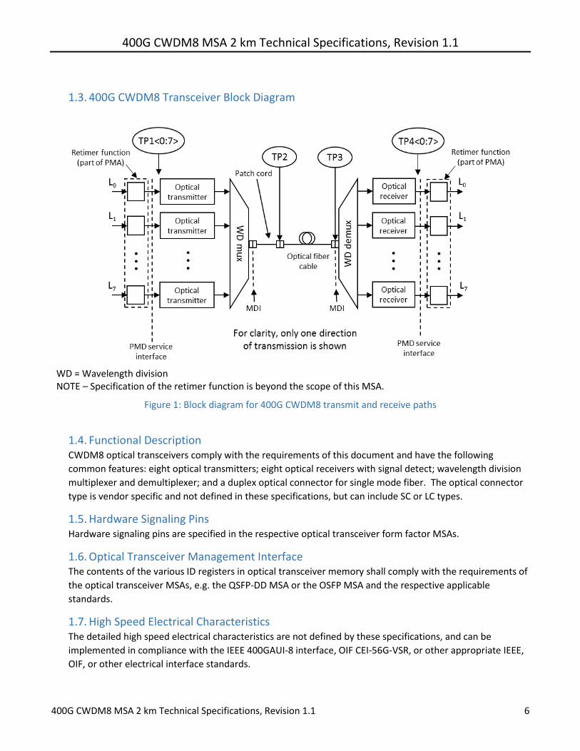
400G CWDM8 MSA 2 km Technical Specifications Revision 11
400G CWDM8 MSA 2 km Technical Specifications Revision 11 7
18 FEC Requirements The optical link is specified to operate at a bit error ratio (BER) of 2 x 10⁻⁴ To support this optical interface
specification the host system is required to enable 400G RS(544514) FEC in accordance with clause 119 of
IEEE 8023bs The option to bypass the Clause 119 RS-FEC correction function is not supported
19 Mechanical Dimensions Mechanical dimensions are defined in the optical module form factor MSA specifications
110 Operating Environment All specified minimum and maximum parameter values shall be met when the host system maintains the
operating case temperature and supply voltages within the optical module vendor specified operating
ranges All minimum and maximum limits apply over the operating life of the system
111 Power Supplies and Power Dissipation Optical transceiver vendors shall specify the optical module power supply requirements in accordance with
the optical module MSA
400G CWDM8 MSA 2 km Technical Specifications Revision 11
400G CWDM8 MSA 2 km Technical Specifications Revision 11 8
2 CWDM8 Optical Specifications
21 Optical Wavelengths The wavelength range for each lane of the 400G CWDM8 optical transceiver is defined in Table 1 The center
wavelengths are spaced at 20 nm
Table 1 Wavelength Range
Lane Center Wavelength Wavelength Range
L0 1271 nm 12645 to 12775 nm
L1 1291 nm 12845 to 12975 nm
L2 1311 nm 13045 to 13175 nm
L3 1331 nm 13245 to 13375 nm
L4 1351 nm 13445 to 13575 nm
L5 1371 nm 13645 to 13775 nm
L6 1391 nm 13845 to 13975 nm
L7 1411 nm 14045 to 14175 nm
22 Optical Specifications The operating range for a CWDM8 transceiver is defined in Table 2 A CWDM8 compliant PMD operates on
single-mode fibers according to the specifications defined in Table 8 and characteristics in Table 9 A PMD
that exceeds the required operating range while meeting all other optical specifications is considered
compliant (eg operating at 3 km meets the operating range requirement of 2 m to 2 km)
Table 2 Operating range
Module type Required operating range
400GE-CWDM8-2 2 m to 2 km
221 CWDM8 Transmitter Optical Specifications The 400G CWDM8 transmitter shall meet the specifications defined in Table 3
Table 3 400G CWDM8 transmit characteristics
Description Minimum Maximum Unit
Signaling rate each lane 53125 plusmn 100 ppm Gbd
Modulation format NRZ
Wavelengths
12645 12845 13045 13245 13445 13645 13845 14045
12775 12975 13175 13375 13575 13775 13975 14175
nm
Side mode suppression ratio (SMSR) 30 - dB
Total average launch power - 85 dBm
Average launch power each lanea -55 25 dBm
Optical modulation amplitude (OMA) each laneb -3 25 dBm
Launch power in OMA minus TDEC each lane -4 - dBm
Difference in launch power between any two lanes (average and OMA) - 4 dB
400G CWDM8 MSA 2 km Technical Specifications Revision 11
400G CWDM8 MSA 2 km Technical Specifications Revision 11 9
Transmitter dispersion and eye closure penalty (TDEC) each lane - 28 dB
Average launch power of OFF transmitter each lane - -30 dBm
Extinction ratio 35 - dB
Optical return loss tolerance - 171 dB
Transmitter reflectance(c) - -26 dB a The minimum requirement for average launch power each lane is informative and not the principal indicator of signal
strength A transmitter with launch power below this value cannot be compliant however a value above this does not
ensure compliance b Even if the TDEC lt 10 dB the minimum OMA must exceed the minimum OMA requirement c Transmitter reflectance is defined looking into the transmitter
222 CWDM8 Receiver Optical Specifications The CWDM4 receiver shall meet the specifications defined in Table 4
Table 4 400G CWDM8 receive characteristics
Description Minimum Maximum Unit
Signaling rate each lane 53125 plusmn 100 ppm Gbd
Wavelengths
12645 12845 13045 13245 13445 13645 13845 14045
12775 12975 13175 13375 13575 13775 13975 14175
nm
Damage threshold each lanea 35 - dBm
Average receive power each laneb -95 25 dBm
Receive power in OMA each lane - 25 dBm
Receiver reflectance - -26 dB
Receiver sensitivity (OMA) each lane at 2 x 10⁻⁴ BERc - -8 dBm
Stressed receiver sensitivity (OMA) each laned - -53 dBm
Conditions of stressed receiver sensitivity test
Stressed eye closure (SEC) each lanee 27 dB
Stressed eye J2 jitter each lanee 033 UI
Stressed eye J4 jitter each lanee 048 UI a The receiver shall be able to tolerate without damage continuous exposure to a signal having this average power level b The minimum requirement for average receive power each lane is informative and not the principal indicator of signal strength A
received power below this value cannot be compliant however a value above this does not ensure compliance c Receiver sensitivity (OMA) each lane is a normative specification d Measured with conformance test signal at TP3 (see 310) for BER = 2 x 10⁻⁴ e Stressed eye closure stressed eye J2 jitter and stressed eye J4 jitter are test conditions for measuring stressed receiver sensitivity
They are not characteristics of the receiver
400G CWDM8 MSA 2 km Technical Specifications Revision 11
400G CWDM8 MSA 2 km Technical Specifications Revision 11 10
223 CWDM8 2 km Interface Illustrative Link Power Budget An illustrative power budget and penalties for CWDM4 are shown in Table 5
Table 5 400G CWDM8 illustrative power budget
Description Value Unit
Power budget (for max TDEC) 68 dB
Operating distance 2 km
Channel insertion loss(a) 4 dB
Maximum discrete reflectance(b) -35 dB
Allocation for penalties (for max TDEC) 28 dB
Additional insertion loss allowed 0 dB
(a) Includes 01dB MPI penalty (b) Assumes 6 connectors in the link
3 Definition of Optical Parameters and Measurement Methods
31 Test Patterns for Optical Parameters All optical measurements shall be made through a short patch cable between 2 m and 5 m in length unless
otherwise specified
Table 6 Patterns for optical parameter testing
Parameter Pattern
Wavelength SSPR
Side mode suppression ratio SSPR
Average optical power SSPR
Optical modulation amplitude (OMA) Square wave
Transmitter dispersion and eye closure penalty (TDEC)(a) SSPR
Extinction ratio SSPR
Transmitter optical waveform SSPR
Stressed receiver sensitivity SSPR
Calibration of OMA for receiver tests PRBS9
Stressed eye closure calibration SSPR
(a) Or RS-FEC encoded scrambled idle according to IEEE8023bs Clause 119
311 Square Wave Pattern Definition A pattern consisting of eight ones followed by an equal run of zeroes may be used as a square wave
312 SSPR Pattern Definition The SSPR pattern is defined as
Total length 32762 bits
All 2^28-1 PRBS28 sequences are generated using taps 25 and 28
Block 1 is 5437 bits of PRBS28 seed=0x0080080 and begins with 8x0111x0112x0 1
Block2 is 1 followed by 72x0
400G CWDM8 MSA 2 km Technical Specifications Revision 11
400G CWDM8 MSA 2 km Technical Specifications Revision 11 11
Block 3 is 5437 bits of PRBS28 seed=0xFFFFFFFF and begins 28x125x03x122x0
Block 4 takes the same sequence as block 1 (omitting the last 3 bits) and codes it - A zero is encoded as a change of output - A one is encoded as no change of output - The output before the first bit is assumed to have been a 0 - This block begins 1010101001010101010110101010101011011010
Blocks 5 to 8 are the inverse of 1 to 4 Under some circumstances (eg to accommodate the restrictions of some pieces of test equipment) it may be desirable to modify this short pattern to have a total length of 32768 bits (2^15) rather than 32762 bits To make use of this option the differentially encoded blocks (blocks 4 and 8) should be extended by 3 bits making these blocks 5437 bits long
32 Skew and Skew Variation Refer to IEEE Std 8023bs Clause 1223 CWDM8 MSA transceivers shall comply with the skew and skew
variation limits of IEEE Std 8023bs clause 12231 and 12232
33 Wavelength Measure per TIAEIA-455-127-A or IEC 61280-1-3
34 Average Optical Power Measure using the methods given in IEC 61280-1-1 with channels not being measured turned off
35 Optical Modulation Amplitude (OMA) Refer to IEEE Std 8023-2015 Clause 5295 OMA is measured with a square wave (8 ones 8 zeroes) test
pattern Each lane may be tested individually with all other lanes turned off or by using an optical filter if
the other lanes are active
36 Transmitter Dispersion and Eye Closure Penalty (TDEC) TDEC shall be as defined in IEEE Std 8023-2015 Clause 9585 with the exceptions that
- The optical to electrical converter bandwidth shall not include the optical channel which shall be
included explicitly as shown in 361 below
- Each optical lane is tested individually using an optical filter to separate the lane under test from the
others The optical filter pass band ripple shall be limited to 05 dB peak-to-peak and the isolation is
chosen such that the ratio of the power in the lane being measured to the sum of the powers of all the
other lanes is greater than 20 dB (see ITU-T G9591 Annex B) The lanes not under test shall be
operating with the test patterns mentioned in 31
361 TDEC Conformance Test Setup A block diagram for the TDEC conformance test is shown in Figure 2 Other measurement
implementations may be used with suitable calibration
400G CWDM8 MSA 2 km Technical Specifications Revision 11
400G CWDM8 MSA 2 km Technical Specifications Revision 11 12
Figure 2 TDEC conformance test setup
Each optical lane is tested individually with all other lanes in operation The optical splitter and variable
reflector are adjusted so that each transmitter is tested with an optical return loss of 171 dB
The combination of the OE and the oscilloscope used to measure the optical waveform has a fourth-
order Bessel-Thomson filter response with a bandwidth of 398 GHz Compensation may be made for
any deviation from an ideal fourth-order Bessel-Thomson response
The clock recovery unit (CRU) has a corner frequency of 4 MHz and a slope of 20 dBdecade
Two tests need to be performed with and without a fiber of 2km length specified in Table 7 The
maximum of the single discrete reflections of the inserted fiber are specified in Table 5 The transmitter
needs to pass both tests with a TDEC specified in Table 3
362 Channel Requirements The transmitter is tested using an optical channel that meets the requirements listed in Table 7
Table 7 Channel Requirements for TDEC Test
Type Dispersion (psnm)a Insertion lossb Optical return lossc
Minimum Maximum
CWDM8 00465λ[1-(1324 λ)4] 00465λ[1-(1300 λ)4] Minimum 171 dB
a The dispersion is measured for the wavelength of the device under test (λ in nm) The coefficient assumes 2 km for CWDM8 b There is no intent to stress the sensitivity of the BERTrsquos optical receiver c The optical return loss is applied at TP2 ie after a 2 meter patch cord
363 TDEC Measurement Method The TDEC measurement method shall follow IEEE Std 8023-2015 Clause 95852 with the following
exceptions
- The four vertical histograms are measured through the eye diagram are centered at 045 UI and 055
UI
- The BER is 24 x 10-4
- The Q factor is 34917
- The formula for the received noise R is
R = radic1198732 + 1198782
400G CWDM8 MSA 2 km Technical Specifications Revision 11
400G CWDM8 MSA 2 km Technical Specifications Revision 11 13
where as in Clause 95852 N represents the lesser of the left and right standard deviations σL and
σR and S is the standard deviation of the noise of the OE and oscilloscope combination Please
refer to the source material for a more detailed description of the calculations
37 Extinction Ratio Extinction ratio is measured using the methods specified in IEC 61280-2-2 with the lanes not under test
turned off
38 Transmitter Optical Waveform (Transmit Eye) Refer to IEEE Std 8023-2012 Clause 8888 with the following exceptions
- The clock recovery unitrsquos high-frequency corner bandwidth is 4 MHz
- The filter nominal reference frequency fr is 398 GHz and the filter tolerances are as specified for STM-64
in ITU-T G691
39 Receiver Sensitivity The nominal sensitivity of each receiver lane is measured in OMA using the setup of Figure 3 The sensitivity must be corrected for any significant reference transmitter impairments including any vertical eye closure It should be measured at the eye center or corrected for off- center sampling The reference transmitter wavelength(s) shall comply with the ranges in Table 4 The reference transmitter is a high-quality instrument grade device which can be implemented by a CW laser modulated by a high-performance modulator It should have the following basic requirements - The risefall times should be less than 6 ps at 20 to 80 - The output optical eye is symmetric and passes the transmitter optical waveform test of 38 - In the center 10 region of the eye the worst-case vertical eye closure penalty as defined in IEEE 8023-
2015 878112 is less than 05 dB - Total jitter less than 02 UI peak-to-peak - RIN of less than -140 dBHz Center of the eye is defined as the time halfway between the left and right sampling points within the eye
where the measured BER is greater than or equal to 24 x 10-4
The clock recovery unit (CRU) used in the sensitivity measurement has a corner frequency of less than or
equal to 4 MHz and a slope of 20 dBdecade When using a clock recovery unit as a clock for BER
measurement passing of low frequency jitter from the data to the clock removes this low-frequency jitter
from the measurement
Figure 3 Test setup for receiver sensitivity
400G CWDM8 MSA 2 km Technical Specifications Revision 11
400G CWDM8 MSA 2 km Technical Specifications Revision 11 14
310 Stressed Receiver Sensitivity Refer to IEEE Std 8023-2015 Cl 9588 with the following exceptions - The test BER is 2 x 10⁻⁴ - The stressed input signal shall be adjusted to provide the stressed eye closure and jitter defined in Table
4 above - Each lane is tested individually with all other Rx and Tx channels turned ON and receiving or transmitting
SSPR signals The maximum OMA difference between the Rx lane under test and the other Rx lanes not under test is 4 dB
- The fourth-order Bessel-Thomson filter has a 3 dB bandwidth of approximately 39 GHz - At least 20 dB of SEC (stressed eye closure) should be created by the selection of the appropriate band-
width for the combination of the low-pass filter and the EO converter
4 Fiber Optic Cabling Model
Figure 4 Fiber optic cabling model
The channel insertion loss is given in Table 8 A channel may contain additional connectors as long as the
optical characteristics of the channel such as attenuation dispersion reflections and polarization mode
dispersion meet the specifications Insertion loss measurements of installed fiber cables are made in
accordance with IEC 61280-4-2 using the one-cord reference method The fiber optic cabling model
(channel) defined here is the same as a simplex fiber optic link segment The term channel is used here for
consistency with generic cabling standards
Table 8 Fiber optic cabling (channel) characteristics
Description CWDM8 Unit
Operating distance 2 km
Channel insertion loss max(ab) 4 dB
Channel insertion loss min 0 dB
Positive dispersion(b) (max) 193 psnm
Negative dispersion(b) (min) -119 psnm
DGD_max(c) 3 ps
Optical return loss (min) 21 dB
(a) These channel loss values include cable connectors and splices (b) Over the wavelength range 12645 to 14175 nm (c) Differential Group Delay (DGD) is the time difference at reception between the fractions of a
pulse that were transmitted in the two principal states of polarization of an optical signal DGD_max is the maximum differential group delay that the system must tolerate
400G CWDM8 MSA 2 km Technical Specifications Revision 11
400G CWDM8 MSA 2 km Technical Specifications Revision 11 15
5 Characteristics of the Fiber Optic Cabling (Channel)
51 Optical Fiber Cable The fiber optic cable requirements are satisfied by cables containing
- IEC 60793-2-50 type B13 single mode fiber or equivalently ITU-T G652 types C and D (low water peak
single mode fiber) or
- IEC 60793-2-50 type B6_a1 and B6_a2 single mode fiber or equivalently ITU-T G657 types A1 and A2
(bend insensitive single mode fiber with low water peak)
Table 9 Fiber characteristics
Description Value Unit
Nominal fiber specification wavelength 1310 nm
Cabled optical fiber attenuation (max) 05a dBkm
Zero dispersion wavelength (λ0) 1300 le λ0 le 1324 nm
Dispersion slope (max) (S0) 0093 psnm2km
a The 05 dBkm attenuation is provided for Outside Plant cable as defined in ANSITIA 568-C3
52 Optical Fiber Connection An optical fiber connection as shown in Figure 4 consists of a mated pair of optical connectors
521 Connection Insertion Loss The maximum link distances for single-mode fiber are calculated based on an allocation of 3 dB total
connection and splice loss For example this allocation supports 6 connections with an average
insertion loss per connection of 05 dB Connections with different loss characteristics may be used
provided the requirements of Table 8 are met
522 Maximum Discrete Reflectance The maximum discrete reflectance shall be less than -35 dB
53 Medium Dependent Interface (MDI) Requirements The PMD is coupled to the fiber optic cabling at the MDI The MDI is the interface between the PMD and the ldquofiber optic cablingrdquo (as shown in Figure 4) Examples of an MDI include the following
a Connectorized fiber pigtail b PMD receptacle
When the MDI is a connector plug and receptacle connection it shall meet the interface performance specifications of IEC 61753-1-1 and IEC 61753-021-2
Note Transmitter compliance testing is performed at TP2 ie after a 2 meter patch cord not at the MDI
400G CWDM8 MSA 2 km Technical Specifications Revision 11
400G CWDM8 MSA 2 km Technical Specifications Revision 11 16
6 CWDM8 Optical Transceiver Color Coding Transceiver modules compliant to the CWDM8 MSA Specifications use a color code to indicate the application This color code can be on a transceiver module bail latch pull tab or other visible feature of the module when installed in a system The color code scheme is specified below
Color Code Application
Turquoise Pantone 3242U 400 Gbs CWDM8 2km reach
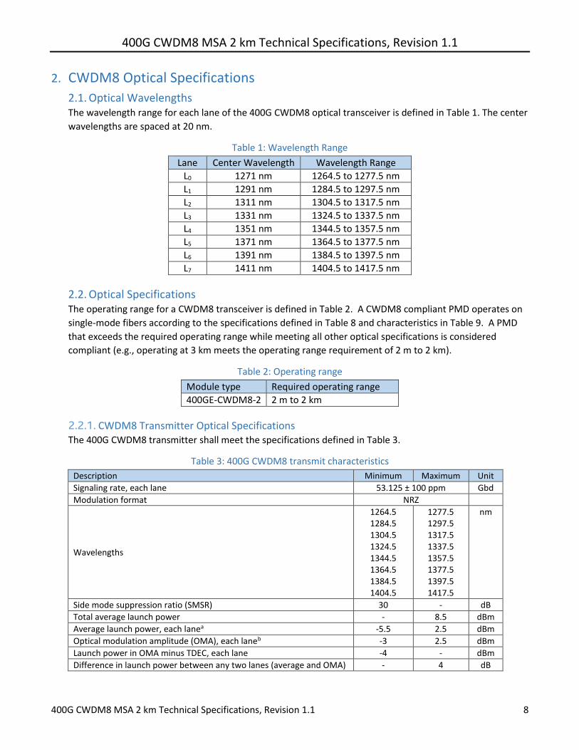
400G CWDM8 MSA 2 km Technical Specifications Revision 11
400G CWDM8 MSA 2 km Technical Specifications Revision 11 9
Transmitter dispersion and eye closure penalty (TDEC) each lane - 28 dB
Average launch power of OFF transmitter each lane - -30 dBm
Extinction ratio 35 - dB
Optical return loss tolerance - 171 dB
Transmitter reflectance(c) - -26 dB a The minimum requirement for average launch power each lane is informative and not the principal indicator of signal
strength A transmitter with launch power below this value cannot be compliant however a value above this does not
ensure compliance b Even if the TDEC lt 10 dB the minimum OMA must exceed the minimum OMA requirement c Transmitter reflectance is defined looking into the transmitter
222 CWDM8 Receiver Optical Specifications The CWDM4 receiver shall meet the specifications defined in Table 4
Table 4 400G CWDM8 receive characteristics
Description Minimum Maximum Unit
Signaling rate each lane 53125 plusmn 100 ppm Gbd
Wavelengths
12645 12845 13045 13245 13445 13645 13845 14045
12775 12975 13175 13375 13575 13775 13975 14175
nm
Damage threshold each lanea 35 - dBm
Average receive power each laneb -95 25 dBm
Receive power in OMA each lane - 25 dBm
Receiver reflectance - -26 dB
Receiver sensitivity (OMA) each lane at 2 x 10⁻⁴ BERc - -8 dBm
Stressed receiver sensitivity (OMA) each laned - -53 dBm
Conditions of stressed receiver sensitivity test
Stressed eye closure (SEC) each lanee 27 dB
Stressed eye J2 jitter each lanee 033 UI
Stressed eye J4 jitter each lanee 048 UI a The receiver shall be able to tolerate without damage continuous exposure to a signal having this average power level b The minimum requirement for average receive power each lane is informative and not the principal indicator of signal strength A
received power below this value cannot be compliant however a value above this does not ensure compliance c Receiver sensitivity (OMA) each lane is a normative specification d Measured with conformance test signal at TP3 (see 310) for BER = 2 x 10⁻⁴ e Stressed eye closure stressed eye J2 jitter and stressed eye J4 jitter are test conditions for measuring stressed receiver sensitivity
They are not characteristics of the receiver
400G CWDM8 MSA 2 km Technical Specifications Revision 11
400G CWDM8 MSA 2 km Technical Specifications Revision 11 10
223 CWDM8 2 km Interface Illustrative Link Power Budget An illustrative power budget and penalties for CWDM4 are shown in Table 5
Table 5 400G CWDM8 illustrative power budget
Description Value Unit
Power budget (for max TDEC) 68 dB
Operating distance 2 km
Channel insertion loss(a) 4 dB
Maximum discrete reflectance(b) -35 dB
Allocation for penalties (for max TDEC) 28 dB
Additional insertion loss allowed 0 dB
(a) Includes 01dB MPI penalty (b) Assumes 6 connectors in the link
3 Definition of Optical Parameters and Measurement Methods
31 Test Patterns for Optical Parameters All optical measurements shall be made through a short patch cable between 2 m and 5 m in length unless
otherwise specified
Table 6 Patterns for optical parameter testing
Parameter Pattern
Wavelength SSPR
Side mode suppression ratio SSPR
Average optical power SSPR
Optical modulation amplitude (OMA) Square wave
Transmitter dispersion and eye closure penalty (TDEC)(a) SSPR
Extinction ratio SSPR
Transmitter optical waveform SSPR
Stressed receiver sensitivity SSPR
Calibration of OMA for receiver tests PRBS9
Stressed eye closure calibration SSPR
(a) Or RS-FEC encoded scrambled idle according to IEEE8023bs Clause 119
311 Square Wave Pattern Definition A pattern consisting of eight ones followed by an equal run of zeroes may be used as a square wave
312 SSPR Pattern Definition The SSPR pattern is defined as
Total length 32762 bits
All 2^28-1 PRBS28 sequences are generated using taps 25 and 28
Block 1 is 5437 bits of PRBS28 seed=0x0080080 and begins with 8x0111x0112x0 1
Block2 is 1 followed by 72x0
400G CWDM8 MSA 2 km Technical Specifications Revision 11
400G CWDM8 MSA 2 km Technical Specifications Revision 11 11
Block 3 is 5437 bits of PRBS28 seed=0xFFFFFFFF and begins 28x125x03x122x0
Block 4 takes the same sequence as block 1 (omitting the last 3 bits) and codes it - A zero is encoded as a change of output - A one is encoded as no change of output - The output before the first bit is assumed to have been a 0 - This block begins 1010101001010101010110101010101011011010
Blocks 5 to 8 are the inverse of 1 to 4 Under some circumstances (eg to accommodate the restrictions of some pieces of test equipment) it may be desirable to modify this short pattern to have a total length of 32768 bits (2^15) rather than 32762 bits To make use of this option the differentially encoded blocks (blocks 4 and 8) should be extended by 3 bits making these blocks 5437 bits long
32 Skew and Skew Variation Refer to IEEE Std 8023bs Clause 1223 CWDM8 MSA transceivers shall comply with the skew and skew
variation limits of IEEE Std 8023bs clause 12231 and 12232
33 Wavelength Measure per TIAEIA-455-127-A or IEC 61280-1-3
34 Average Optical Power Measure using the methods given in IEC 61280-1-1 with channels not being measured turned off
35 Optical Modulation Amplitude (OMA) Refer to IEEE Std 8023-2015 Clause 5295 OMA is measured with a square wave (8 ones 8 zeroes) test
pattern Each lane may be tested individually with all other lanes turned off or by using an optical filter if
the other lanes are active
36 Transmitter Dispersion and Eye Closure Penalty (TDEC) TDEC shall be as defined in IEEE Std 8023-2015 Clause 9585 with the exceptions that
- The optical to electrical converter bandwidth shall not include the optical channel which shall be
included explicitly as shown in 361 below
- Each optical lane is tested individually using an optical filter to separate the lane under test from the
others The optical filter pass band ripple shall be limited to 05 dB peak-to-peak and the isolation is
chosen such that the ratio of the power in the lane being measured to the sum of the powers of all the
other lanes is greater than 20 dB (see ITU-T G9591 Annex B) The lanes not under test shall be
operating with the test patterns mentioned in 31
361 TDEC Conformance Test Setup A block diagram for the TDEC conformance test is shown in Figure 2 Other measurement
implementations may be used with suitable calibration
400G CWDM8 MSA 2 km Technical Specifications Revision 11
400G CWDM8 MSA 2 km Technical Specifications Revision 11 12
Figure 2 TDEC conformance test setup
Each optical lane is tested individually with all other lanes in operation The optical splitter and variable
reflector are adjusted so that each transmitter is tested with an optical return loss of 171 dB
The combination of the OE and the oscilloscope used to measure the optical waveform has a fourth-
order Bessel-Thomson filter response with a bandwidth of 398 GHz Compensation may be made for
any deviation from an ideal fourth-order Bessel-Thomson response
The clock recovery unit (CRU) has a corner frequency of 4 MHz and a slope of 20 dBdecade
Two tests need to be performed with and without a fiber of 2km length specified in Table 7 The
maximum of the single discrete reflections of the inserted fiber are specified in Table 5 The transmitter
needs to pass both tests with a TDEC specified in Table 3
362 Channel Requirements The transmitter is tested using an optical channel that meets the requirements listed in Table 7
Table 7 Channel Requirements for TDEC Test
Type Dispersion (psnm)a Insertion lossb Optical return lossc
Minimum Maximum
CWDM8 00465λ[1-(1324 λ)4] 00465λ[1-(1300 λ)4] Minimum 171 dB
a The dispersion is measured for the wavelength of the device under test (λ in nm) The coefficient assumes 2 km for CWDM8 b There is no intent to stress the sensitivity of the BERTrsquos optical receiver c The optical return loss is applied at TP2 ie after a 2 meter patch cord
363 TDEC Measurement Method The TDEC measurement method shall follow IEEE Std 8023-2015 Clause 95852 with the following
exceptions
- The four vertical histograms are measured through the eye diagram are centered at 045 UI and 055
UI
- The BER is 24 x 10-4
- The Q factor is 34917
- The formula for the received noise R is
R = radic1198732 + 1198782
400G CWDM8 MSA 2 km Technical Specifications Revision 11
400G CWDM8 MSA 2 km Technical Specifications Revision 11 13
where as in Clause 95852 N represents the lesser of the left and right standard deviations σL and
σR and S is the standard deviation of the noise of the OE and oscilloscope combination Please
refer to the source material for a more detailed description of the calculations
37 Extinction Ratio Extinction ratio is measured using the methods specified in IEC 61280-2-2 with the lanes not under test
turned off
38 Transmitter Optical Waveform (Transmit Eye) Refer to IEEE Std 8023-2012 Clause 8888 with the following exceptions
- The clock recovery unitrsquos high-frequency corner bandwidth is 4 MHz
- The filter nominal reference frequency fr is 398 GHz and the filter tolerances are as specified for STM-64
in ITU-T G691
39 Receiver Sensitivity The nominal sensitivity of each receiver lane is measured in OMA using the setup of Figure 3 The sensitivity must be corrected for any significant reference transmitter impairments including any vertical eye closure It should be measured at the eye center or corrected for off- center sampling The reference transmitter wavelength(s) shall comply with the ranges in Table 4 The reference transmitter is a high-quality instrument grade device which can be implemented by a CW laser modulated by a high-performance modulator It should have the following basic requirements - The risefall times should be less than 6 ps at 20 to 80 - The output optical eye is symmetric and passes the transmitter optical waveform test of 38 - In the center 10 region of the eye the worst-case vertical eye closure penalty as defined in IEEE 8023-
2015 878112 is less than 05 dB - Total jitter less than 02 UI peak-to-peak - RIN of less than -140 dBHz Center of the eye is defined as the time halfway between the left and right sampling points within the eye
where the measured BER is greater than or equal to 24 x 10-4
The clock recovery unit (CRU) used in the sensitivity measurement has a corner frequency of less than or
equal to 4 MHz and a slope of 20 dBdecade When using a clock recovery unit as a clock for BER
measurement passing of low frequency jitter from the data to the clock removes this low-frequency jitter
from the measurement
Figure 3 Test setup for receiver sensitivity
400G CWDM8 MSA 2 km Technical Specifications Revision 11
400G CWDM8 MSA 2 km Technical Specifications Revision 11 14
310 Stressed Receiver Sensitivity Refer to IEEE Std 8023-2015 Cl 9588 with the following exceptions - The test BER is 2 x 10⁻⁴ - The stressed input signal shall be adjusted to provide the stressed eye closure and jitter defined in Table
4 above - Each lane is tested individually with all other Rx and Tx channels turned ON and receiving or transmitting
SSPR signals The maximum OMA difference between the Rx lane under test and the other Rx lanes not under test is 4 dB
- The fourth-order Bessel-Thomson filter has a 3 dB bandwidth of approximately 39 GHz - At least 20 dB of SEC (stressed eye closure) should be created by the selection of the appropriate band-
width for the combination of the low-pass filter and the EO converter
4 Fiber Optic Cabling Model
Figure 4 Fiber optic cabling model
The channel insertion loss is given in Table 8 A channel may contain additional connectors as long as the
optical characteristics of the channel such as attenuation dispersion reflections and polarization mode
dispersion meet the specifications Insertion loss measurements of installed fiber cables are made in
accordance with IEC 61280-4-2 using the one-cord reference method The fiber optic cabling model
(channel) defined here is the same as a simplex fiber optic link segment The term channel is used here for
consistency with generic cabling standards
Table 8 Fiber optic cabling (channel) characteristics
Description CWDM8 Unit
Operating distance 2 km
Channel insertion loss max(ab) 4 dB
Channel insertion loss min 0 dB
Positive dispersion(b) (max) 193 psnm
Negative dispersion(b) (min) -119 psnm
DGD_max(c) 3 ps
Optical return loss (min) 21 dB
(a) These channel loss values include cable connectors and splices (b) Over the wavelength range 12645 to 14175 nm (c) Differential Group Delay (DGD) is the time difference at reception between the fractions of a
pulse that were transmitted in the two principal states of polarization of an optical signal DGD_max is the maximum differential group delay that the system must tolerate
400G CWDM8 MSA 2 km Technical Specifications Revision 11
400G CWDM8 MSA 2 km Technical Specifications Revision 11 15
5 Characteristics of the Fiber Optic Cabling (Channel)
51 Optical Fiber Cable The fiber optic cable requirements are satisfied by cables containing
- IEC 60793-2-50 type B13 single mode fiber or equivalently ITU-T G652 types C and D (low water peak
single mode fiber) or
- IEC 60793-2-50 type B6_a1 and B6_a2 single mode fiber or equivalently ITU-T G657 types A1 and A2
(bend insensitive single mode fiber with low water peak)
Table 9 Fiber characteristics
Description Value Unit
Nominal fiber specification wavelength 1310 nm
Cabled optical fiber attenuation (max) 05a dBkm
Zero dispersion wavelength (λ0) 1300 le λ0 le 1324 nm
Dispersion slope (max) (S0) 0093 psnm2km
a The 05 dBkm attenuation is provided for Outside Plant cable as defined in ANSITIA 568-C3
52 Optical Fiber Connection An optical fiber connection as shown in Figure 4 consists of a mated pair of optical connectors
521 Connection Insertion Loss The maximum link distances for single-mode fiber are calculated based on an allocation of 3 dB total
connection and splice loss For example this allocation supports 6 connections with an average
insertion loss per connection of 05 dB Connections with different loss characteristics may be used
provided the requirements of Table 8 are met
522 Maximum Discrete Reflectance The maximum discrete reflectance shall be less than -35 dB
53 Medium Dependent Interface (MDI) Requirements The PMD is coupled to the fiber optic cabling at the MDI The MDI is the interface between the PMD and the ldquofiber optic cablingrdquo (as shown in Figure 4) Examples of an MDI include the following
a Connectorized fiber pigtail b PMD receptacle
When the MDI is a connector plug and receptacle connection it shall meet the interface performance specifications of IEC 61753-1-1 and IEC 61753-021-2
Note Transmitter compliance testing is performed at TP2 ie after a 2 meter patch cord not at the MDI
400G CWDM8 MSA 2 km Technical Specifications Revision 11
400G CWDM8 MSA 2 km Technical Specifications Revision 11 16
6 CWDM8 Optical Transceiver Color Coding Transceiver modules compliant to the CWDM8 MSA Specifications use a color code to indicate the application This color code can be on a transceiver module bail latch pull tab or other visible feature of the module when installed in a system The color code scheme is specified below
Color Code Application
Turquoise Pantone 3242U 400 Gbs CWDM8 2km reach
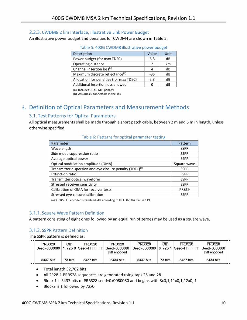
400G CWDM8 MSA 2 km Technical Specifications Revision 11
400G CWDM8 MSA 2 km Technical Specifications Revision 11 10
223 CWDM8 2 km Interface Illustrative Link Power Budget An illustrative power budget and penalties for CWDM4 are shown in Table 5
Table 5 400G CWDM8 illustrative power budget
Description Value Unit
Power budget (for max TDEC) 68 dB
Operating distance 2 km
Channel insertion loss(a) 4 dB
Maximum discrete reflectance(b) -35 dB
Allocation for penalties (for max TDEC) 28 dB
Additional insertion loss allowed 0 dB
(a) Includes 01dB MPI penalty (b) Assumes 6 connectors in the link
3 Definition of Optical Parameters and Measurement Methods
31 Test Patterns for Optical Parameters All optical measurements shall be made through a short patch cable between 2 m and 5 m in length unless
otherwise specified
Table 6 Patterns for optical parameter testing
Parameter Pattern
Wavelength SSPR
Side mode suppression ratio SSPR
Average optical power SSPR
Optical modulation amplitude (OMA) Square wave
Transmitter dispersion and eye closure penalty (TDEC)(a) SSPR
Extinction ratio SSPR
Transmitter optical waveform SSPR
Stressed receiver sensitivity SSPR
Calibration of OMA for receiver tests PRBS9
Stressed eye closure calibration SSPR
(a) Or RS-FEC encoded scrambled idle according to IEEE8023bs Clause 119
311 Square Wave Pattern Definition A pattern consisting of eight ones followed by an equal run of zeroes may be used as a square wave
312 SSPR Pattern Definition The SSPR pattern is defined as
Total length 32762 bits
All 2^28-1 PRBS28 sequences are generated using taps 25 and 28
Block 1 is 5437 bits of PRBS28 seed=0x0080080 and begins with 8x0111x0112x0 1
Block2 is 1 followed by 72x0
400G CWDM8 MSA 2 km Technical Specifications Revision 11
400G CWDM8 MSA 2 km Technical Specifications Revision 11 11
Block 3 is 5437 bits of PRBS28 seed=0xFFFFFFFF and begins 28x125x03x122x0
Block 4 takes the same sequence as block 1 (omitting the last 3 bits) and codes it - A zero is encoded as a change of output - A one is encoded as no change of output - The output before the first bit is assumed to have been a 0 - This block begins 1010101001010101010110101010101011011010
Blocks 5 to 8 are the inverse of 1 to 4 Under some circumstances (eg to accommodate the restrictions of some pieces of test equipment) it may be desirable to modify this short pattern to have a total length of 32768 bits (2^15) rather than 32762 bits To make use of this option the differentially encoded blocks (blocks 4 and 8) should be extended by 3 bits making these blocks 5437 bits long
32 Skew and Skew Variation Refer to IEEE Std 8023bs Clause 1223 CWDM8 MSA transceivers shall comply with the skew and skew
variation limits of IEEE Std 8023bs clause 12231 and 12232
33 Wavelength Measure per TIAEIA-455-127-A or IEC 61280-1-3
34 Average Optical Power Measure using the methods given in IEC 61280-1-1 with channels not being measured turned off
35 Optical Modulation Amplitude (OMA) Refer to IEEE Std 8023-2015 Clause 5295 OMA is measured with a square wave (8 ones 8 zeroes) test
pattern Each lane may be tested individually with all other lanes turned off or by using an optical filter if
the other lanes are active
36 Transmitter Dispersion and Eye Closure Penalty (TDEC) TDEC shall be as defined in IEEE Std 8023-2015 Clause 9585 with the exceptions that
- The optical to electrical converter bandwidth shall not include the optical channel which shall be
included explicitly as shown in 361 below
- Each optical lane is tested individually using an optical filter to separate the lane under test from the
others The optical filter pass band ripple shall be limited to 05 dB peak-to-peak and the isolation is
chosen such that the ratio of the power in the lane being measured to the sum of the powers of all the
other lanes is greater than 20 dB (see ITU-T G9591 Annex B) The lanes not under test shall be
operating with the test patterns mentioned in 31
361 TDEC Conformance Test Setup A block diagram for the TDEC conformance test is shown in Figure 2 Other measurement
implementations may be used with suitable calibration
400G CWDM8 MSA 2 km Technical Specifications Revision 11
400G CWDM8 MSA 2 km Technical Specifications Revision 11 12
Figure 2 TDEC conformance test setup
Each optical lane is tested individually with all other lanes in operation The optical splitter and variable
reflector are adjusted so that each transmitter is tested with an optical return loss of 171 dB
The combination of the OE and the oscilloscope used to measure the optical waveform has a fourth-
order Bessel-Thomson filter response with a bandwidth of 398 GHz Compensation may be made for
any deviation from an ideal fourth-order Bessel-Thomson response
The clock recovery unit (CRU) has a corner frequency of 4 MHz and a slope of 20 dBdecade
Two tests need to be performed with and without a fiber of 2km length specified in Table 7 The
maximum of the single discrete reflections of the inserted fiber are specified in Table 5 The transmitter
needs to pass both tests with a TDEC specified in Table 3
362 Channel Requirements The transmitter is tested using an optical channel that meets the requirements listed in Table 7
Table 7 Channel Requirements for TDEC Test
Type Dispersion (psnm)a Insertion lossb Optical return lossc
Minimum Maximum
CWDM8 00465λ[1-(1324 λ)4] 00465λ[1-(1300 λ)4] Minimum 171 dB
a The dispersion is measured for the wavelength of the device under test (λ in nm) The coefficient assumes 2 km for CWDM8 b There is no intent to stress the sensitivity of the BERTrsquos optical receiver c The optical return loss is applied at TP2 ie after a 2 meter patch cord
363 TDEC Measurement Method The TDEC measurement method shall follow IEEE Std 8023-2015 Clause 95852 with the following
exceptions
- The four vertical histograms are measured through the eye diagram are centered at 045 UI and 055
UI
- The BER is 24 x 10-4
- The Q factor is 34917
- The formula for the received noise R is
R = radic1198732 + 1198782
400G CWDM8 MSA 2 km Technical Specifications Revision 11
400G CWDM8 MSA 2 km Technical Specifications Revision 11 13
where as in Clause 95852 N represents the lesser of the left and right standard deviations σL and
σR and S is the standard deviation of the noise of the OE and oscilloscope combination Please
refer to the source material for a more detailed description of the calculations
37 Extinction Ratio Extinction ratio is measured using the methods specified in IEC 61280-2-2 with the lanes not under test
turned off
38 Transmitter Optical Waveform (Transmit Eye) Refer to IEEE Std 8023-2012 Clause 8888 with the following exceptions
- The clock recovery unitrsquos high-frequency corner bandwidth is 4 MHz
- The filter nominal reference frequency fr is 398 GHz and the filter tolerances are as specified for STM-64
in ITU-T G691
39 Receiver Sensitivity The nominal sensitivity of each receiver lane is measured in OMA using the setup of Figure 3 The sensitivity must be corrected for any significant reference transmitter impairments including any vertical eye closure It should be measured at the eye center or corrected for off- center sampling The reference transmitter wavelength(s) shall comply with the ranges in Table 4 The reference transmitter is a high-quality instrument grade device which can be implemented by a CW laser modulated by a high-performance modulator It should have the following basic requirements - The risefall times should be less than 6 ps at 20 to 80 - The output optical eye is symmetric and passes the transmitter optical waveform test of 38 - In the center 10 region of the eye the worst-case vertical eye closure penalty as defined in IEEE 8023-
2015 878112 is less than 05 dB - Total jitter less than 02 UI peak-to-peak - RIN of less than -140 dBHz Center of the eye is defined as the time halfway between the left and right sampling points within the eye
where the measured BER is greater than or equal to 24 x 10-4
The clock recovery unit (CRU) used in the sensitivity measurement has a corner frequency of less than or
equal to 4 MHz and a slope of 20 dBdecade When using a clock recovery unit as a clock for BER
measurement passing of low frequency jitter from the data to the clock removes this low-frequency jitter
from the measurement
Figure 3 Test setup for receiver sensitivity
400G CWDM8 MSA 2 km Technical Specifications Revision 11
400G CWDM8 MSA 2 km Technical Specifications Revision 11 14
310 Stressed Receiver Sensitivity Refer to IEEE Std 8023-2015 Cl 9588 with the following exceptions - The test BER is 2 x 10⁻⁴ - The stressed input signal shall be adjusted to provide the stressed eye closure and jitter defined in Table
4 above - Each lane is tested individually with all other Rx and Tx channels turned ON and receiving or transmitting
SSPR signals The maximum OMA difference between the Rx lane under test and the other Rx lanes not under test is 4 dB
- The fourth-order Bessel-Thomson filter has a 3 dB bandwidth of approximately 39 GHz - At least 20 dB of SEC (stressed eye closure) should be created by the selection of the appropriate band-
width for the combination of the low-pass filter and the EO converter
4 Fiber Optic Cabling Model
Figure 4 Fiber optic cabling model
The channel insertion loss is given in Table 8 A channel may contain additional connectors as long as the
optical characteristics of the channel such as attenuation dispersion reflections and polarization mode
dispersion meet the specifications Insertion loss measurements of installed fiber cables are made in
accordance with IEC 61280-4-2 using the one-cord reference method The fiber optic cabling model
(channel) defined here is the same as a simplex fiber optic link segment The term channel is used here for
consistency with generic cabling standards
Table 8 Fiber optic cabling (channel) characteristics
Description CWDM8 Unit
Operating distance 2 km
Channel insertion loss max(ab) 4 dB
Channel insertion loss min 0 dB
Positive dispersion(b) (max) 193 psnm
Negative dispersion(b) (min) -119 psnm
DGD_max(c) 3 ps
Optical return loss (min) 21 dB
(a) These channel loss values include cable connectors and splices (b) Over the wavelength range 12645 to 14175 nm (c) Differential Group Delay (DGD) is the time difference at reception between the fractions of a
pulse that were transmitted in the two principal states of polarization of an optical signal DGD_max is the maximum differential group delay that the system must tolerate
400G CWDM8 MSA 2 km Technical Specifications Revision 11
400G CWDM8 MSA 2 km Technical Specifications Revision 11 15
5 Characteristics of the Fiber Optic Cabling (Channel)
51 Optical Fiber Cable The fiber optic cable requirements are satisfied by cables containing
- IEC 60793-2-50 type B13 single mode fiber or equivalently ITU-T G652 types C and D (low water peak
single mode fiber) or
- IEC 60793-2-50 type B6_a1 and B6_a2 single mode fiber or equivalently ITU-T G657 types A1 and A2
(bend insensitive single mode fiber with low water peak)
Table 9 Fiber characteristics
Description Value Unit
Nominal fiber specification wavelength 1310 nm
Cabled optical fiber attenuation (max) 05a dBkm
Zero dispersion wavelength (λ0) 1300 le λ0 le 1324 nm
Dispersion slope (max) (S0) 0093 psnm2km
a The 05 dBkm attenuation is provided for Outside Plant cable as defined in ANSITIA 568-C3
52 Optical Fiber Connection An optical fiber connection as shown in Figure 4 consists of a mated pair of optical connectors
521 Connection Insertion Loss The maximum link distances for single-mode fiber are calculated based on an allocation of 3 dB total
connection and splice loss For example this allocation supports 6 connections with an average
insertion loss per connection of 05 dB Connections with different loss characteristics may be used
provided the requirements of Table 8 are met
522 Maximum Discrete Reflectance The maximum discrete reflectance shall be less than -35 dB
53 Medium Dependent Interface (MDI) Requirements The PMD is coupled to the fiber optic cabling at the MDI The MDI is the interface between the PMD and the ldquofiber optic cablingrdquo (as shown in Figure 4) Examples of an MDI include the following
a Connectorized fiber pigtail b PMD receptacle
When the MDI is a connector plug and receptacle connection it shall meet the interface performance specifications of IEC 61753-1-1 and IEC 61753-021-2
Note Transmitter compliance testing is performed at TP2 ie after a 2 meter patch cord not at the MDI
400G CWDM8 MSA 2 km Technical Specifications Revision 11
400G CWDM8 MSA 2 km Technical Specifications Revision 11 16
6 CWDM8 Optical Transceiver Color Coding Transceiver modules compliant to the CWDM8 MSA Specifications use a color code to indicate the application This color code can be on a transceiver module bail latch pull tab or other visible feature of the module when installed in a system The color code scheme is specified below
Color Code Application
Turquoise Pantone 3242U 400 Gbs CWDM8 2km reach
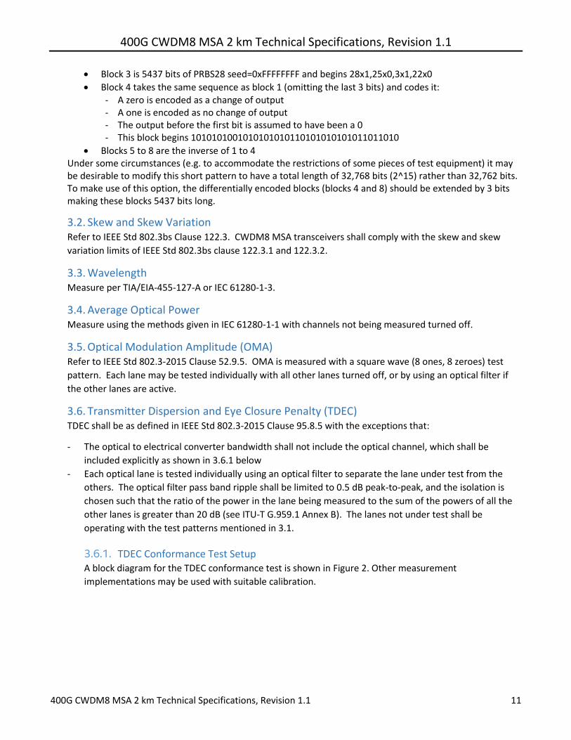
400G CWDM8 MSA 2 km Technical Specifications Revision 11
400G CWDM8 MSA 2 km Technical Specifications Revision 11 11
Block 3 is 5437 bits of PRBS28 seed=0xFFFFFFFF and begins 28x125x03x122x0
Block 4 takes the same sequence as block 1 (omitting the last 3 bits) and codes it - A zero is encoded as a change of output - A one is encoded as no change of output - The output before the first bit is assumed to have been a 0 - This block begins 1010101001010101010110101010101011011010
Blocks 5 to 8 are the inverse of 1 to 4 Under some circumstances (eg to accommodate the restrictions of some pieces of test equipment) it may be desirable to modify this short pattern to have a total length of 32768 bits (2^15) rather than 32762 bits To make use of this option the differentially encoded blocks (blocks 4 and 8) should be extended by 3 bits making these blocks 5437 bits long
32 Skew and Skew Variation Refer to IEEE Std 8023bs Clause 1223 CWDM8 MSA transceivers shall comply with the skew and skew
variation limits of IEEE Std 8023bs clause 12231 and 12232
33 Wavelength Measure per TIAEIA-455-127-A or IEC 61280-1-3
34 Average Optical Power Measure using the methods given in IEC 61280-1-1 with channels not being measured turned off
35 Optical Modulation Amplitude (OMA) Refer to IEEE Std 8023-2015 Clause 5295 OMA is measured with a square wave (8 ones 8 zeroes) test
pattern Each lane may be tested individually with all other lanes turned off or by using an optical filter if
the other lanes are active
36 Transmitter Dispersion and Eye Closure Penalty (TDEC) TDEC shall be as defined in IEEE Std 8023-2015 Clause 9585 with the exceptions that
- The optical to electrical converter bandwidth shall not include the optical channel which shall be
included explicitly as shown in 361 below
- Each optical lane is tested individually using an optical filter to separate the lane under test from the
others The optical filter pass band ripple shall be limited to 05 dB peak-to-peak and the isolation is
chosen such that the ratio of the power in the lane being measured to the sum of the powers of all the
other lanes is greater than 20 dB (see ITU-T G9591 Annex B) The lanes not under test shall be
operating with the test patterns mentioned in 31
361 TDEC Conformance Test Setup A block diagram for the TDEC conformance test is shown in Figure 2 Other measurement
implementations may be used with suitable calibration
400G CWDM8 MSA 2 km Technical Specifications Revision 11
400G CWDM8 MSA 2 km Technical Specifications Revision 11 12
Figure 2 TDEC conformance test setup
Each optical lane is tested individually with all other lanes in operation The optical splitter and variable
reflector are adjusted so that each transmitter is tested with an optical return loss of 171 dB
The combination of the OE and the oscilloscope used to measure the optical waveform has a fourth-
order Bessel-Thomson filter response with a bandwidth of 398 GHz Compensation may be made for
any deviation from an ideal fourth-order Bessel-Thomson response
The clock recovery unit (CRU) has a corner frequency of 4 MHz and a slope of 20 dBdecade
Two tests need to be performed with and without a fiber of 2km length specified in Table 7 The
maximum of the single discrete reflections of the inserted fiber are specified in Table 5 The transmitter
needs to pass both tests with a TDEC specified in Table 3
362 Channel Requirements The transmitter is tested using an optical channel that meets the requirements listed in Table 7
Table 7 Channel Requirements for TDEC Test
Type Dispersion (psnm)a Insertion lossb Optical return lossc
Minimum Maximum
CWDM8 00465λ[1-(1324 λ)4] 00465λ[1-(1300 λ)4] Minimum 171 dB
a The dispersion is measured for the wavelength of the device under test (λ in nm) The coefficient assumes 2 km for CWDM8 b There is no intent to stress the sensitivity of the BERTrsquos optical receiver c The optical return loss is applied at TP2 ie after a 2 meter patch cord
363 TDEC Measurement Method The TDEC measurement method shall follow IEEE Std 8023-2015 Clause 95852 with the following
exceptions
- The four vertical histograms are measured through the eye diagram are centered at 045 UI and 055
UI
- The BER is 24 x 10-4
- The Q factor is 34917
- The formula for the received noise R is
R = radic1198732 + 1198782
400G CWDM8 MSA 2 km Technical Specifications Revision 11
400G CWDM8 MSA 2 km Technical Specifications Revision 11 13
where as in Clause 95852 N represents the lesser of the left and right standard deviations σL and
σR and S is the standard deviation of the noise of the OE and oscilloscope combination Please
refer to the source material for a more detailed description of the calculations
37 Extinction Ratio Extinction ratio is measured using the methods specified in IEC 61280-2-2 with the lanes not under test
turned off
38 Transmitter Optical Waveform (Transmit Eye) Refer to IEEE Std 8023-2012 Clause 8888 with the following exceptions
- The clock recovery unitrsquos high-frequency corner bandwidth is 4 MHz
- The filter nominal reference frequency fr is 398 GHz and the filter tolerances are as specified for STM-64
in ITU-T G691
39 Receiver Sensitivity The nominal sensitivity of each receiver lane is measured in OMA using the setup of Figure 3 The sensitivity must be corrected for any significant reference transmitter impairments including any vertical eye closure It should be measured at the eye center or corrected for off- center sampling The reference transmitter wavelength(s) shall comply with the ranges in Table 4 The reference transmitter is a high-quality instrument grade device which can be implemented by a CW laser modulated by a high-performance modulator It should have the following basic requirements - The risefall times should be less than 6 ps at 20 to 80 - The output optical eye is symmetric and passes the transmitter optical waveform test of 38 - In the center 10 region of the eye the worst-case vertical eye closure penalty as defined in IEEE 8023-
2015 878112 is less than 05 dB - Total jitter less than 02 UI peak-to-peak - RIN of less than -140 dBHz Center of the eye is defined as the time halfway between the left and right sampling points within the eye
where the measured BER is greater than or equal to 24 x 10-4
The clock recovery unit (CRU) used in the sensitivity measurement has a corner frequency of less than or
equal to 4 MHz and a slope of 20 dBdecade When using a clock recovery unit as a clock for BER
measurement passing of low frequency jitter from the data to the clock removes this low-frequency jitter
from the measurement
Figure 3 Test setup for receiver sensitivity
400G CWDM8 MSA 2 km Technical Specifications Revision 11
400G CWDM8 MSA 2 km Technical Specifications Revision 11 14
310 Stressed Receiver Sensitivity Refer to IEEE Std 8023-2015 Cl 9588 with the following exceptions - The test BER is 2 x 10⁻⁴ - The stressed input signal shall be adjusted to provide the stressed eye closure and jitter defined in Table
4 above - Each lane is tested individually with all other Rx and Tx channels turned ON and receiving or transmitting
SSPR signals The maximum OMA difference between the Rx lane under test and the other Rx lanes not under test is 4 dB
- The fourth-order Bessel-Thomson filter has a 3 dB bandwidth of approximately 39 GHz - At least 20 dB of SEC (stressed eye closure) should be created by the selection of the appropriate band-
width for the combination of the low-pass filter and the EO converter
4 Fiber Optic Cabling Model
Figure 4 Fiber optic cabling model
The channel insertion loss is given in Table 8 A channel may contain additional connectors as long as the
optical characteristics of the channel such as attenuation dispersion reflections and polarization mode
dispersion meet the specifications Insertion loss measurements of installed fiber cables are made in
accordance with IEC 61280-4-2 using the one-cord reference method The fiber optic cabling model
(channel) defined here is the same as a simplex fiber optic link segment The term channel is used here for
consistency with generic cabling standards
Table 8 Fiber optic cabling (channel) characteristics
Description CWDM8 Unit
Operating distance 2 km
Channel insertion loss max(ab) 4 dB
Channel insertion loss min 0 dB
Positive dispersion(b) (max) 193 psnm
Negative dispersion(b) (min) -119 psnm
DGD_max(c) 3 ps
Optical return loss (min) 21 dB
(a) These channel loss values include cable connectors and splices (b) Over the wavelength range 12645 to 14175 nm (c) Differential Group Delay (DGD) is the time difference at reception between the fractions of a
pulse that were transmitted in the two principal states of polarization of an optical signal DGD_max is the maximum differential group delay that the system must tolerate
400G CWDM8 MSA 2 km Technical Specifications Revision 11
400G CWDM8 MSA 2 km Technical Specifications Revision 11 15
5 Characteristics of the Fiber Optic Cabling (Channel)
51 Optical Fiber Cable The fiber optic cable requirements are satisfied by cables containing
- IEC 60793-2-50 type B13 single mode fiber or equivalently ITU-T G652 types C and D (low water peak
single mode fiber) or
- IEC 60793-2-50 type B6_a1 and B6_a2 single mode fiber or equivalently ITU-T G657 types A1 and A2
(bend insensitive single mode fiber with low water peak)
Table 9 Fiber characteristics
Description Value Unit
Nominal fiber specification wavelength 1310 nm
Cabled optical fiber attenuation (max) 05a dBkm
Zero dispersion wavelength (λ0) 1300 le λ0 le 1324 nm
Dispersion slope (max) (S0) 0093 psnm2km
a The 05 dBkm attenuation is provided for Outside Plant cable as defined in ANSITIA 568-C3
52 Optical Fiber Connection An optical fiber connection as shown in Figure 4 consists of a mated pair of optical connectors
521 Connection Insertion Loss The maximum link distances for single-mode fiber are calculated based on an allocation of 3 dB total
connection and splice loss For example this allocation supports 6 connections with an average
insertion loss per connection of 05 dB Connections with different loss characteristics may be used
provided the requirements of Table 8 are met
522 Maximum Discrete Reflectance The maximum discrete reflectance shall be less than -35 dB
53 Medium Dependent Interface (MDI) Requirements The PMD is coupled to the fiber optic cabling at the MDI The MDI is the interface between the PMD and the ldquofiber optic cablingrdquo (as shown in Figure 4) Examples of an MDI include the following
a Connectorized fiber pigtail b PMD receptacle
When the MDI is a connector plug and receptacle connection it shall meet the interface performance specifications of IEC 61753-1-1 and IEC 61753-021-2
Note Transmitter compliance testing is performed at TP2 ie after a 2 meter patch cord not at the MDI
400G CWDM8 MSA 2 km Technical Specifications Revision 11
400G CWDM8 MSA 2 km Technical Specifications Revision 11 16
6 CWDM8 Optical Transceiver Color Coding Transceiver modules compliant to the CWDM8 MSA Specifications use a color code to indicate the application This color code can be on a transceiver module bail latch pull tab or other visible feature of the module when installed in a system The color code scheme is specified below
Color Code Application
Turquoise Pantone 3242U 400 Gbs CWDM8 2km reach
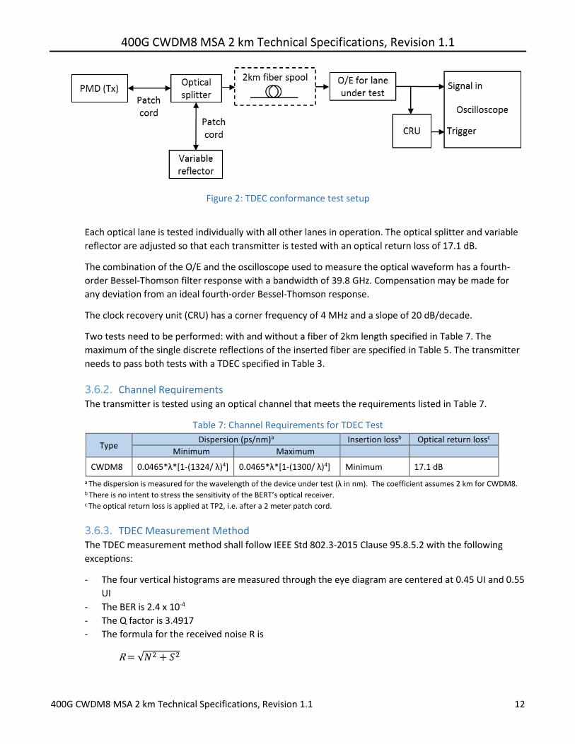
400G CWDM8 MSA 2 km Technical Specifications Revision 11
400G CWDM8 MSA 2 km Technical Specifications Revision 11 12
Figure 2 TDEC conformance test setup
Each optical lane is tested individually with all other lanes in operation The optical splitter and variable
reflector are adjusted so that each transmitter is tested with an optical return loss of 171 dB
The combination of the OE and the oscilloscope used to measure the optical waveform has a fourth-
order Bessel-Thomson filter response with a bandwidth of 398 GHz Compensation may be made for
any deviation from an ideal fourth-order Bessel-Thomson response
The clock recovery unit (CRU) has a corner frequency of 4 MHz and a slope of 20 dBdecade
Two tests need to be performed with and without a fiber of 2km length specified in Table 7 The
maximum of the single discrete reflections of the inserted fiber are specified in Table 5 The transmitter
needs to pass both tests with a TDEC specified in Table 3
362 Channel Requirements The transmitter is tested using an optical channel that meets the requirements listed in Table 7
Table 7 Channel Requirements for TDEC Test
Type Dispersion (psnm)a Insertion lossb Optical return lossc
Minimum Maximum
CWDM8 00465λ[1-(1324 λ)4] 00465λ[1-(1300 λ)4] Minimum 171 dB
a The dispersion is measured for the wavelength of the device under test (λ in nm) The coefficient assumes 2 km for CWDM8 b There is no intent to stress the sensitivity of the BERTrsquos optical receiver c The optical return loss is applied at TP2 ie after a 2 meter patch cord
363 TDEC Measurement Method The TDEC measurement method shall follow IEEE Std 8023-2015 Clause 95852 with the following
exceptions
- The four vertical histograms are measured through the eye diagram are centered at 045 UI and 055
UI
- The BER is 24 x 10-4
- The Q factor is 34917
- The formula for the received noise R is
R = radic1198732 + 1198782
400G CWDM8 MSA 2 km Technical Specifications Revision 11
400G CWDM8 MSA 2 km Technical Specifications Revision 11 13
where as in Clause 95852 N represents the lesser of the left and right standard deviations σL and
σR and S is the standard deviation of the noise of the OE and oscilloscope combination Please
refer to the source material for a more detailed description of the calculations
37 Extinction Ratio Extinction ratio is measured using the methods specified in IEC 61280-2-2 with the lanes not under test
turned off
38 Transmitter Optical Waveform (Transmit Eye) Refer to IEEE Std 8023-2012 Clause 8888 with the following exceptions
- The clock recovery unitrsquos high-frequency corner bandwidth is 4 MHz
- The filter nominal reference frequency fr is 398 GHz and the filter tolerances are as specified for STM-64
in ITU-T G691
39 Receiver Sensitivity The nominal sensitivity of each receiver lane is measured in OMA using the setup of Figure 3 The sensitivity must be corrected for any significant reference transmitter impairments including any vertical eye closure It should be measured at the eye center or corrected for off- center sampling The reference transmitter wavelength(s) shall comply with the ranges in Table 4 The reference transmitter is a high-quality instrument grade device which can be implemented by a CW laser modulated by a high-performance modulator It should have the following basic requirements - The risefall times should be less than 6 ps at 20 to 80 - The output optical eye is symmetric and passes the transmitter optical waveform test of 38 - In the center 10 region of the eye the worst-case vertical eye closure penalty as defined in IEEE 8023-
2015 878112 is less than 05 dB - Total jitter less than 02 UI peak-to-peak - RIN of less than -140 dBHz Center of the eye is defined as the time halfway between the left and right sampling points within the eye
where the measured BER is greater than or equal to 24 x 10-4
The clock recovery unit (CRU) used in the sensitivity measurement has a corner frequency of less than or
equal to 4 MHz and a slope of 20 dBdecade When using a clock recovery unit as a clock for BER
measurement passing of low frequency jitter from the data to the clock removes this low-frequency jitter
from the measurement
Figure 3 Test setup for receiver sensitivity
400G CWDM8 MSA 2 km Technical Specifications Revision 11
400G CWDM8 MSA 2 km Technical Specifications Revision 11 14
310 Stressed Receiver Sensitivity Refer to IEEE Std 8023-2015 Cl 9588 with the following exceptions - The test BER is 2 x 10⁻⁴ - The stressed input signal shall be adjusted to provide the stressed eye closure and jitter defined in Table
4 above - Each lane is tested individually with all other Rx and Tx channels turned ON and receiving or transmitting
SSPR signals The maximum OMA difference between the Rx lane under test and the other Rx lanes not under test is 4 dB
- The fourth-order Bessel-Thomson filter has a 3 dB bandwidth of approximately 39 GHz - At least 20 dB of SEC (stressed eye closure) should be created by the selection of the appropriate band-
width for the combination of the low-pass filter and the EO converter
4 Fiber Optic Cabling Model
Figure 4 Fiber optic cabling model
The channel insertion loss is given in Table 8 A channel may contain additional connectors as long as the
optical characteristics of the channel such as attenuation dispersion reflections and polarization mode
dispersion meet the specifications Insertion loss measurements of installed fiber cables are made in
accordance with IEC 61280-4-2 using the one-cord reference method The fiber optic cabling model
(channel) defined here is the same as a simplex fiber optic link segment The term channel is used here for
consistency with generic cabling standards
Table 8 Fiber optic cabling (channel) characteristics
Description CWDM8 Unit
Operating distance 2 km
Channel insertion loss max(ab) 4 dB
Channel insertion loss min 0 dB
Positive dispersion(b) (max) 193 psnm
Negative dispersion(b) (min) -119 psnm
DGD_max(c) 3 ps
Optical return loss (min) 21 dB
(a) These channel loss values include cable connectors and splices (b) Over the wavelength range 12645 to 14175 nm (c) Differential Group Delay (DGD) is the time difference at reception between the fractions of a
pulse that were transmitted in the two principal states of polarization of an optical signal DGD_max is the maximum differential group delay that the system must tolerate
400G CWDM8 MSA 2 km Technical Specifications Revision 11
400G CWDM8 MSA 2 km Technical Specifications Revision 11 15
5 Characteristics of the Fiber Optic Cabling (Channel)
51 Optical Fiber Cable The fiber optic cable requirements are satisfied by cables containing
- IEC 60793-2-50 type B13 single mode fiber or equivalently ITU-T G652 types C and D (low water peak
single mode fiber) or
- IEC 60793-2-50 type B6_a1 and B6_a2 single mode fiber or equivalently ITU-T G657 types A1 and A2
(bend insensitive single mode fiber with low water peak)
Table 9 Fiber characteristics
Description Value Unit
Nominal fiber specification wavelength 1310 nm
Cabled optical fiber attenuation (max) 05a dBkm
Zero dispersion wavelength (λ0) 1300 le λ0 le 1324 nm
Dispersion slope (max) (S0) 0093 psnm2km
a The 05 dBkm attenuation is provided for Outside Plant cable as defined in ANSITIA 568-C3
52 Optical Fiber Connection An optical fiber connection as shown in Figure 4 consists of a mated pair of optical connectors
521 Connection Insertion Loss The maximum link distances for single-mode fiber are calculated based on an allocation of 3 dB total
connection and splice loss For example this allocation supports 6 connections with an average
insertion loss per connection of 05 dB Connections with different loss characteristics may be used
provided the requirements of Table 8 are met
522 Maximum Discrete Reflectance The maximum discrete reflectance shall be less than -35 dB
53 Medium Dependent Interface (MDI) Requirements The PMD is coupled to the fiber optic cabling at the MDI The MDI is the interface between the PMD and the ldquofiber optic cablingrdquo (as shown in Figure 4) Examples of an MDI include the following
a Connectorized fiber pigtail b PMD receptacle
When the MDI is a connector plug and receptacle connection it shall meet the interface performance specifications of IEC 61753-1-1 and IEC 61753-021-2
Note Transmitter compliance testing is performed at TP2 ie after a 2 meter patch cord not at the MDI
400G CWDM8 MSA 2 km Technical Specifications Revision 11
400G CWDM8 MSA 2 km Technical Specifications Revision 11 16
6 CWDM8 Optical Transceiver Color Coding Transceiver modules compliant to the CWDM8 MSA Specifications use a color code to indicate the application This color code can be on a transceiver module bail latch pull tab or other visible feature of the module when installed in a system The color code scheme is specified below
Color Code Application
Turquoise Pantone 3242U 400 Gbs CWDM8 2km reach
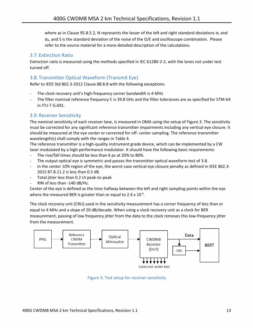
400G CWDM8 MSA 2 km Technical Specifications Revision 11
400G CWDM8 MSA 2 km Technical Specifications Revision 11 15
5 Characteristics of the Fiber Optic Cabling (Channel)
51 Optical Fiber Cable The fiber optic cable requirements are satisfied by cables containing
- IEC 60793-2-50 type B13 single mode fiber or equivalently ITU-T G652 types C and D (low water peak
single mode fiber) or
- IEC 60793-2-50 type B6_a1 and B6_a2 single mode fiber or equivalently ITU-T G657 types A1 and A2
(bend insensitive single mode fiber with low water peak)
Table 9 Fiber characteristics
Description Value Unit
Nominal fiber specification wavelength 1310 nm
Cabled optical fiber attenuation (max) 05a dBkm
Zero dispersion wavelength (λ0) 1300 le λ0 le 1324 nm
Dispersion slope (max) (S0) 0093 psnm2km
a The 05 dBkm attenuation is provided for Outside Plant cable as defined in ANSITIA 568-C3
52 Optical Fiber Connection An optical fiber connection as shown in Figure 4 consists of a mated pair of optical connectors
521 Connection Insertion Loss The maximum link distances for single-mode fiber are calculated based on an allocation of 3 dB total
connection and splice loss For example this allocation supports 6 connections with an average
insertion loss per connection of 05 dB Connections with different loss characteristics may be used
provided the requirements of Table 8 are met
522 Maximum Discrete Reflectance The maximum discrete reflectance shall be less than -35 dB
53 Medium Dependent Interface (MDI) Requirements The PMD is coupled to the fiber optic cabling at the MDI The MDI is the interface between the PMD and the ldquofiber optic cablingrdquo (as shown in Figure 4) Examples of an MDI include the following
a Connectorized fiber pigtail b PMD receptacle
When the MDI is a connector plug and receptacle connection it shall meet the interface performance specifications of IEC 61753-1-1 and IEC 61753-021-2
Note Transmitter compliance testing is performed at TP2 ie after a 2 meter patch cord not at the MDI
400G CWDM8 MSA 2 km Technical Specifications Revision 11
400G CWDM8 MSA 2 km Technical Specifications Revision 11 16
6 CWDM8 Optical Transceiver Color Coding Transceiver modules compliant to the CWDM8 MSA Specifications use a color code to indicate the application This color code can be on a transceiver module bail latch pull tab or other visible feature of the module when installed in a system The color code scheme is specified below
Color Code Application
Turquoise Pantone 3242U 400 Gbs CWDM8 2km reach