407 class notes 1x, 2013 materials
TRANSCRIPT

Classification of Materials
Most materials can be broadly classified into three main groups: metalsceramics and polymers. In addition, modern engineering materials includecomposites, semiconductors, and biomaterials.
Metals-- normally combinations of metallic elements (alloys), e.g. Cu/Zn and
Pb/Sn.
-- optically opaque
-- strong and ductile
-- good electrical and thermal conductors
-- mainly structural applications.
Ceramics-- compounds of metallic and non-metallic elements, e.g. oxides and
carbides
-- can be optically transparent
-- hard and brittle
-- heat and corrosion resistant
-- structural and functional applications
1

Polymers-- organic compounds of carbon, hydrogen and other non-metallic
elements, e.g. polyethylene and polystyrene
-- low density, flexible and formable
-- resistant to chemical attack
-- mainly structural applications
Composites-- composed of more than one material type, e.g. glass fiber in a polymer
matrix.
-- combines best characteristics of each of the component materials
-- high specific strength and fracture resistant
-- mainly structural applications
Semiconductors-- electrical properties intermediate between conductors and insulators
-- properties extremely sensitive to minute traces of impurity elements, e.g. P and B in Si
-- vapor processing of thin planar arrays of doped-Si forms the basis of the integrated circuit industry
-- functional applications
2

Biomaterials
-- materials that are non-toxic when implanted in the human body
-- used for replacement of diseased or damaged body parts, e.g. hip
implants
Current Materials Challenges
-- reduce energy use in transportation systems by developing (1) low
cost, high performance structural composites for weight reduction,
and (2) ceramic engines for increased operating efficiency.
-- develop materials for sustainable energy production systems, such
as wind turbines and solar cells.
-- improve quality of the environment by (1) developing cleaner
materials refining and processing technologies, and (2) increasing
recycling efforts.
-- develop nanostructured materials and technologies for the next
generation of miniaturized engineered systems.
3

Atomic Bonding in Solids
A.Primary Bonds
Strong bonds (~100 kcal/mol) arising from transfer or sharing of
valence electrons.
1. Ionic bond
-- transfer of valence electrons
-- electron localization (ionic species)
-- non-directional bonding
-- NaCl, ZnO, Li2O, etc.
-- extremities of Periodic Table
2. Covalent bond
-- sharing of valence electrons
-- partial electron delocalization (molecular unit)
-- hybridization of electron orbitals
-- highly directional bonding
-- H2, H2O, CH4, graphite, diamond, fullerene, etc.
4

3. Metallic bond
-- complete sharing of valence electrons (free electron gas)-- complete electron delocalization-- non-directional bonding-- no valency restrictions (alloying)-- Fe, Cu, Fe-Ni, Cu-Zn, etc.
B. Secondary Bonds
Weak bonds (~1 kcal/mol) arising from dipole interactions. Responsible for bonding between electrically neutral atoms or molecules
1. Permanent dipole-- arises when centers of positive and negative charge in a
molecule do not coincide-- directional-- asymmetric ―polar‖ molecules, such as H2O, H2S, NH3, CF2H2,
etc.
2. Induced dipole-- arises from permanent dipole in one molecular group inducing
a dipole in a neighboring group-- directional
5

3. Fluctuating dipole
-- arises from fluctuating charge distribution (no permanent dipole)
-- non-directional
-- inert gases (Ne, Ar, …) and symmetric molecules (CH4, CCl4, …)
C. Hydrogen BondIntermediate bond (~5 kcal/mol)
-- arises when H atom forms a bridge between two electronegative atoms
-- highly directional
-- nylon, cellulose, etc.
D. Addition (or Chain) PolymerizationPolymerization consists of joining a large number of molecules together
-- broken double bond gives two carbon orbitals for bonding
-- directional
-- chain-like structure that is called a polymer
-- polyethylene, polystyrene, etc.
6

Schematics of Secondary Bonds
(a) Electrically symmetric atom
(b) Induced atomic dipole
Hydrogen bonding in hydrogen
fluoride (HF)
Polar hydrogen chloride (HCl)
molecule
7

Ionic Bond
This is easiest to visualize:
-- results from strong electrostatic attraction between oppositely charged ions
-- stable ionic aggregates due to ions with filled outer shells
-- non-directional bonding permits close packing
-- combination of elements with low ionization energy (e.g. Na) and high electron affinity (e.g. Cl)
Ionization Energy is the energy required to remove the least tightly bound electron from an atom (forms positive ion)
Electron affinity is the energy released when an electron is captured by an atom (forms negative ion).
8

Figure 1 – An example of an ionic bond showing electron transfer
from Na to Cl to form Na+ cation and Cl- anion pair.
The ionization energy of Na Na+ is 5.14 eV, whereas the electron
affinity of Cl Cl- is 4.02 eV. Hence, the net energy (work) required
to create a pair of isolated Na+ and Cl- ions is 1.12 eV.
9

Figure 2 – (a) The bond-force curve showing the location of the equilibrium
separation distance x0. Note the approximately linear slope of the total force
curve in the vicinity of x0. (b) The bond-energy curve for the ionic compound
NaCl showing the location of the equilibrium separation distance x0.
Interaction Energy
Consider the interaction between two point charges Q1 and Q2 separated by
distance r.
10

The interaction energy E is the sum of two terms: attractive energy EA and repulsiveenergy ER
E = EA + ER
(attractive) (repulsive)
= (1)
(negative) (positive)
εo is permittivity of vacuum, b and n are constants, which depend on ion
type; n ~ 8-10.
Rearranging terms
0dr
dE*rr
0r
nb
r4
dr
dE)1n(2
0
21
(2)n
0
21
*)r(
b
*r4
n
1
no
21
r
b
r4
11

(3)n
0
21
b*)r(
b
*r4
QQE
Substituting (2) in (3)
Cohesive Energy
Figure 3—A unit cell for the rock salt, or
sodium chloride (NaCl) crystal structure.
n
11
*r4
QQE
0
21
b
Now from (1)

Na+ ion has 6 first nearest neighbor Cl- ions at r*.
Na+ ion has 12 second nearest neighbor Na+ ions at 2 r*.
etc. …
By summing the contributions from all ions, it can be shown that the
cohesive energy/mol is
where N is Avogadro’s number, and A is the Madelung constant, which
depends on structure type.
For NaCl, one electronic charge is involved in transfer of valence electron;
hence Q1 Q2 = (+e) · (-e) = -e2
n
11
*r4
AQQNE
0
21
n
11
*r4
ANeE
0
2
13

Shorter bond distance r* for ZnO reflects stronger interaction energy between
divalent ions.
Since Q1Q2 = (-2e) (+2e) = - 4e2 for ZnO, the cohesive energy/mol is at least four
times that of NaCl.
Characteristics of Ionic Crystals
Coordination number is defined as number of nearest neighbors at the bond
distance.
-- NaCl has CN = 6
-- other ionic crystals have different values, e.g. CsCl has CN = 8
-- determined by relative size of anion and cation
Substance A r*(Å) n Cohesive energy
(kcal/mol)
Na+Cl-
Zn++O--
1.75
1.64
2.81
1.97
8
8
181
964
14

Ionic Radius is defined as the radius of the hard sphere that represents the
ion.
-- radius of anion is usually larger than that of the neutralatom.
-- radius of cation is usually smaller than that of the neutral
atom.
CN = 6
Consider NaCl structure (see Table 1), where each Na+ cation is surrounded by six Cl- anions at the bond distance.
Element Charge at
given radius
Ionic radius
(Å)
Atomic
radius (À)
Sodium
Chlorine
Magnesium
Oxygen
+1
-1
+2
-2
0.98
1.81
0.78
1.32
1.86
0.91
1.59
0.60
15

RA = ionic radius of anion (Cl-)
RC = ionic radius of cation (Na+)
AACA R22R8)RR(2
2A
2A
2CA )R2()R2()RR(2
AC R12R
414.012R
R
A
C
16

This is the smallest value of RC/RA for which all 6 anions touch the cation, called the critical radius ratio.
-- larger values allowed
-- smaller values not allowed
Figure 4 – Stable and unstable anion-cation coordination configurations; large circles represent anions; small circles represent cations.
CN = 4
Consider ZnS structure (see Table 1), where each Zn2+ cation (0.83Å) is surrounded by four S2- anions (1.74Å) at the bond distance.
2
3RR CA 2R2 A
17

Table 1. The critical (r/R) ratio for each coordination number.
2
23RC
2
23RC
2
23RC
= 0.225
2
23 CR
12
6
R
R
A
C
Note that for crystals having
equal numbers of anions
and cations, only CN values
of 2, 3, 4, 6, 8 and 12 satisfy
symmetry requirements.
18

Crystal Structures
We have examined the forces responsible for aggregation of atoms ormolecules. Now we will consider how they are organized or distributed inspace.
Periodic arrays – crystalline materials
Random arrays – amorphous materials
Combination arrays – semicrystalline materials
Crystal lattice is defined as an array of points, infinite in extent, in which every point has identical surroundings.
Unit cell is the smallest region that completely defines the crystal lattice
-- vertices of unit cell are known as lattice points
-- lengths of unit cell are known as lattice parameters
19

Figure 5 – Possible unit cells for a 2-D space lattice: (a)
square, (b) rectangle, and (c) parallelogram.
There are 14 possible arrangements for 3-D lattices, which are
known as Bravais lattices. These can be grouped into 7 crystal
systems, based on edge lengths of unit cell (unit vectors) and the
angles between them.20

Figure 6 –The 14 Bravais lattices grouped into the 7 crystal systems. The restrictions on the lattice parameters a, b, and c and the angles between
the edges of the unit cell , β, and γ are listed for each unit cell. 21

Miller Indices
Most common convention used to denote points, directions, and planes
in crystal lattices
Points
Defined as fractional multiples of
the unit cell edge lengths
Right-hand Cartesian coordinate
system used to denote specific
points, e.g. 1,0,0.
Directions
Defined as the line(s) between
two points or vectors
Specific directions denoted by
square brackets, e.g. [111]; families
of directions denoted by angle
brackets, e.g. <111>
22

Angle between directions [h1k11] and [h2k22] is given by:
)kh()kh(
)kkhh(cos
22
22
22
21
21
21
212121
23
Planes
Defined as the reciprocals of the intercepts on the coordinate axes

Specific planes denoted by parenthesis, e.g. (111).
Families of planes denoted by braces, e.g. {111}.
24

Structures of Metals
Three main types:
-- body centered cubic (bcc)
-- face centered cubic (fcc)
-- hexagonal close packed (hcp)
25

fcc and hcp structures formed by different stacking sequences of close-packed
planes.
ABABABA……….hcp Both have
ABCABCA……….fcc CN = 12
Figure 7 – Close packed stacking sequence (ABCABCA…) for fcc structure26

Figure 8 – Close packed stacking sequence (ABABABA…) for
hcp structure.
Density
Calculate the density of fcc aluminum: atomic mass =
26.98; a = 4.04 x 10⁻⁸ cm; A0 = 6.02 x 10²³ mol-1
27

Packing Factor
Calculate packing factor (PF) for bcc, fcc and hcp structures.
(PF = volume of atoms/volume of unit cell)
3
24
23
cm/g72.210x94.65
10x93.17
v
m
28
Actual measured density is 2.70 g/cm3
bcc structure

0.68 8
3bccPF
Since ao =3
4r
3
0
3
34
2a
rPFbcc
fcc structure
29

hcp structure
Same as for fcc, since both structures are ideally close-packed, with CN = 12.
PF hcp = 0.74
23
PFfcc
30
3
fcca
r3
4
4PF
2
r4Since a0 =
0.74
30

Interstitial Sites
The locations of the largest holes in bcc, fcc and hcp structures areknown as interstitial sites
fcc structure
Largest hole in an fcc structure is located at the center of the unit cell.
-- known as an octahedral site, since the polyhedron connecting nearest neighbor atoms has 8 sides
-- there are 12 equivalent octahedral sites located at edge centers of the unit cell
-- each edge site is shared by four unit cells, hence there are 4 = [(12 x ¼) + (1 x 1)] octahedral sites per unit cell
-- if hole radius is k, then the radius ratio k/r = 0.414
-- hence, atoms about 40% of the size of the host atoms can fit into octahedral sites
The fcc structure also contains tetrahedral sites, located at ¼, ¼, ¼ -type positions in the unit cell.
-- there are 8 equivalent tetrahedral sites that lie completely within the unit cell
31

-- the radius ratio, k/r, for a tetrahedral site is 0.225
-- hence, atoms about 20% of the size of the host atoms can fit intotetrahedral sites
Thus, there are twice as many tetrahedral sites as octahedral sites, andeach tetrahedral site is about one-half the diameter of an octahedral site.
bcc structure
This structure also contains both octahedral and tetrahedral sites
-- octahedral sites are located at face centers and edge centers of
the unit cell, giving a total of 6 sites per unit cell and k/r = 0.155.
-- tetrahedral sites are located at ¼, ½, 0 – type positions, giving atotal of 12 tetrahedral sites per unit cell and k/r = 0.291.
Thus, there are twice as many tetrahedral sites as octahedral sites, and
each tetrahedral site is about twice the diameter of an octahedral site.
hcp structure
Similar to fcc, as indicated in Table 2.
32

Table 2. The size and number of tetrahedral and octahedral interstitial
sites in the BCC, FCC, and HCP crystal structures. The sizes of the
interstitial sties are given in terms of the radius ratio (k/r) where k is the
radius of the largest atom that can ―fit‖ into the interstitial position and r
is the radius of the host atoms. The number of interstitial sites is given in
terms of both the number of sites per cell and, in parentheses, the
number of sites per host atom.
Crystal
Structure
Size of
tetrahedral
sites
Size of
octahedral
sites
Number of
tetrahedral sites
per unit cell (per
host atom)
Number of
octahedral sites
per unit cell (per
host atom)
BCC
FCC
HCP
k/r = 0.291
k/r = 0.225
k/r = 0.225
k/r = 0.155
k/r = 0.414
k/r = 0.414
12 (6)
8 (2)
12 (2)
6 (3)
4 (1)
6 (1)
33

Figure 9 – The locations of the interstitial sites in the common crystal
structures: (a) octahedral sites in FCC, (b) tetrahedral sites in FCC, (c)
octahedral sites in BCC, (d) tetrahedral sites in BCC, (e) octahedral sites in HCP, and (f) tetrahedral sites in HCP.
34

Structures of Ceramics
The structures of many ceramic crystals can be visualized in terms ofstacking of close-packed planes of anions, with interstitial sites occupiedby the cations.
Two types of interstitial sites:-- tetrahedral (CN=4)-- octahedral (CN=6)
Crystal structures determined by:-- stacking sequence (fcc vs. hcp)-- manner in which interstitial sites are occupied
Figure 10 -- The stacking of one
plane of close-packed spheres
(anions) on top of another:
tetrahedral and octahedral
positions between the planes
are designated by T and O,
respectively
Example – NaCl structure
-- fcc array of close-packed anions of the {111} type
-- cations reside in octahedral sites, each with 6 nearest neighbor anions
-- all octahedral sites are occupied35

*Other ionic structures can be understood in similar manner.
Figure 11 – A section of the rock salt
crystal structure from which a corner
has been removed. The exposed plane
of anions (dark spheres inside the
triangle) is a {111}-type plane: the
cations (light spheres) occupy the
interstitial octahedral positions.Density
Ac
Ac
NV
AAn
n = number of formula units within unit cell
Ac = sum of at. wt. of cations
AA = sum of at. wt. of anions
Vc = volume of unit cell
NA = Av. number
Density
36

Calculate the density of NaCl.
n´ =4
AC = ANa = 22.99 g/mole
AA = ACl = 35.45 g/mole
VC = a3
23388 10023.61081.11002.12
)45.3599.22(4
3cm/.g14.2
81.1rCl
1.02rNa
3ClNa
3c r2r2aV
ClNar2r2a
Å
Å
37The experimental value is 2.16 g/cm3

AX-Type Crystal Structures
Equal numbers of cations and anions, known as AX compounds.
NaCl(CN = 6)
CsCl(CN = 8)
38

39

AmXP-Type Crystal Structures
When charges on cations and anions are not the same, a compound with
the formula AmXP can exist, e.g. CaF2
RC/RA = 0.8, so that CN = 8
half of center positions only are occupied
by Ca2+ ions
AmBnXP-Type Crystal Structures
Compounds that have more than one type of
cation (A and B)—formula for barium titanate is
BaTiO3 (perovskite structure).
40

Silicate Ceramics
The basic building block of all silicate ceramics (amorphous and crystalline)
is the tetrahedron.
-- each silicon atom is tetrahedrally bonded to four oxygen atoms
-- since each oxygen atom requires an extra electron to achieve a stable
electronic structure, a charge of –4 is associated with every tetrahedron.
Figure 12 – A silicon-oxygen (SiO4)4- tetrahedron.
Si4+ = 0.39 Å Hence r Si (ion) /r O (ion) = 0.3
O2- = 1.32 Å41

This value is within the stability range 0.225 r/R < 0.414 (Table 3) fortetrahedral coordination (CN=4). Since the Si-O bond is mixed ionic andcovalent (about 50:50), the tetrahedron satisfies the bondingrequirements of both ionic radius ratio and covalent directionality.
Various silicate ceramics arise from the different ways in which the(Si04)
4- units combine into one-, two-, or three-dimensional structures.Because of the high charge on the Si4+ ion, the tetrahedral units areseldom joined edge to edge and never face to face, but almost alwaysshare corners, with no more than two tetrahedra sharing a corner.
Figure 13 – Effect of corner edge, and face sharing on cation-cation
separation. The distances S1:S2:S3 are in the ratio 1:0.58:0.33; that is,
cation-cation repulsion increases on going from left to right, which
tends to destabilize the structure. 42

43
Silica
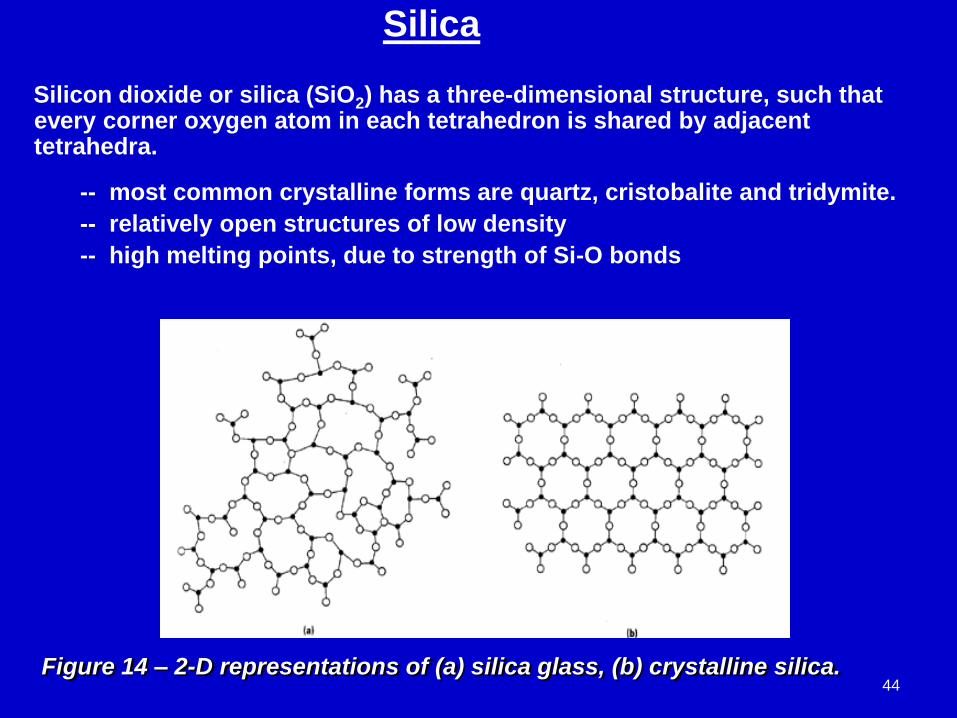
Silicon dioxide or silica (SiO2) has a three-dimensional structure, such that every corner oxygen atom in each tetrahedron is shared by adjacent tetrahedra.
-- most common crystalline forms are quartz, cristobalite and tridymite.
-- relatively open structures of low density
-- high melting points, due to strength of Si-O bonds
Figure 14 – 2-D representations of (a) silica glass, (b) crystalline silica.44

Silica glass
Also known as vitreous silica, silica glass has a highly disordered
structure, i.e. it lacks the long-range order characteristic of crystalline
silica, Fig. 14.
-- Oxides, such as B2O3 and GeO2, which readily form glassy
structures, are referred as network formers. When added to a
silica glass, they substitute for the silicate tetrahedra, so that the
long-range order is retained.
45

-- Oxides, such as Na2O and K2O, which are incapable of forming glassy
structures, are referred as network modifiers. When added to a silica
glass, they break-up the tetrahedral network and create a more
disordered structure.
-- Oxides, such as TiO2 and Al2O3, in which the cations substitute for
silicon and help to stabilize the network, are called intermediates.
The addition of modifiers and intermediates lowers the melting point and
viscosity of the glass, making it easier to form into useful shapes. Thus,
glass containers and windows are made from low melting point soda-lime-
silica glasses, while furnace tubes are made from high melting point vitreous
silica.
Pyrex, a glass composition containing the network formers SiO2 and B2O3,
and the network modifiers Na2O and CaO, has properties intermediate
between those of soda-lime-silicate glass and vitreous silica, e.g. it has about
three times the thermal shock resistance of silica glass, but does not require
the high processing temperature of vitreous silica.
46

Layered silicates
A two-dimensional sheet is formed by sharing of three oxygen atoms in
a planar array of tetrahedra.
-- formula unit is (Si2O5)2-
-- a negative charge is associated with the unbonded oxygen
atoms projecting out of the plane.
Figure 15 – Schematic
representation of the two-
dimensional silicate sheet
structure having a repeat unit
formula of (Si2O5)2-.
Such a negatively charged sheet can bond with an equivalent positively
charged sheet to form an electrically neutral structure.
-- sheet or layered silicate structures are characteristic of clays
and other minerals 47

-- bonding within a two-layered sheet is strong (ionic-covalent), whereas bonding between adjacent sheets is relatively weak (van der Waals).
Clays
Aluminosilicates that contain chemically bound water.
-- crystal structures are relatively complicated
-- when water is added, clays become very plastic; so-called hydroplasticity
-- can be fired at relatively low temperature to form a dense and strong ceramic
Kaolinite
Compound is formed by bonding between Al2(OH)42+ and (Si2O5)
2- layers.
-- formula unit is Al2(OH)4 Si2O5
-- crystalline kaolinite is composed of many such double layers, stacked one upon the other
-- additive to paper products
48

Figure 16 – The structure of
kaolinite clay.
Talc
Compound comprises 1 sheet of Mg3(OH)24+ + 2 sheets of (Si2O5)
2-
-- formula unit is Mg3(OH)2 (Si2O5)2
-- slips easily, like graphite
-- absorbs water49

Glass Properties
Glass transition temperature
For an amorphous or non-crystalline material, the glass transition
temperature (Tg) is the critical temperature that separates glassy
behavior from rubbery behavior, in the time scale of the experiment.
-- most easily detected via measurements of changes in specific volume (1/σ = v/unit mass) associated with heating or cooling a material
-- upon heating, the material undergoes a transition from the glassy state to the supercooled liquid state, and then to the fully liquid state.
50

Figure 17 – Specific volume as a function of temperature for a series of
materials. (a) The liquid-to-crystalline solid transformation. A
discontinuous change in volume occurs at the melting temperature Tm. (b)
The liquid-to-glass transformation (the liquid-to-crystal curve is shown for
reference). The temperature range in which the slope of the liquid-glass
curve changes is the glass transition temperature Tg. (c) Specific volume
versus temperature for a semicrystalline material. The discontinuous
change in volume occurs at Tm, and a change in slope occurs at Tg. 51

Viscosity-temperature behavior
The temperature dependence of the viscosity of a glassy material is the key to proper selection of processing parameters.
-- melting point (viscosity 100 P) is the temperature where the glass is fluid enough to be considered a liquid.
-- working point (viscosity 104 P) is the temperature where the glass is easily deformed.
-- softening point (viscosity 4 x 10⁷ P) is the maximum temperature where glass can be handled without distortion.
-- annealing point (viscosity 1013 P) is the temperature were any residual stress in the glass can be eliminated.
-- strain point (viscosity 3 x 10¹⁴ P) is the temperature where fracture occurs before plastic deformation.
Most glass-forming operations are carried out in the working range, which is between the working and softening temperature.
52

Figure 18 – Logarithm of viscosity versus temperature for fused
silica and several silica glasses. 53

Structures of Polymers
Hydrocarbon molecules
Most polymers are derived from hydrocarbon precursors. It is instructive, therefore, to consider the structures of some typical hydrocarbon molecules.
All four valence electrons in carbon participate in bonding. Moreover, hybridization of s and p orbitals of the valence electrons gives directional bonding.
-- 4 equivalent sp3 orbitals, as in methane and ethane
-- 3 equivalent sp2 orbitals, as in ethylene
-- 2 equivalent sp1 orbitals, as in acetylene
54

single bond -- formed by overlapping sp3 orbitals with the orbitals of other atoms
double bond -- formed by overlapping sp2 orbitals with the orbitals of two different carbon atoms
triple bond -- formed by overlapping sp1 orbitals with the orbitals of two different carbon atoms
Saturated hydrocarbons
sp3 orbitals of both CH4 and C2H6 directed towards the corners of a
regular tetrahedron 55

Unsaturated hydrocarbons
56

-- Activator (catalyst) is needed to start process of polymerization. For example, ethylene gas can be transformed into polyethylene solid by heating under pressure in the presence of a catalyst.
-- Polymerization process begins when an active mer is formed by reaction of an ethylene gas molecule with a catalyst species (R). Polymer chain is then formed by the sequential addition of polyethylene monomer units. In so doing, the active site is transferred to each end-unit monomer as it is linked to the growing chain.
Polymer molecules
Directional nature of covalent bonds enables carbon atoms to form long-chain
molecules.
57

nHH
CC
HH
||
||
Figure 19 – For polyethylene, (a) a schematic representation of mer and
chain structures, and (b) a perspective of the molecule, indicating the
zigzag backbone structure.
Hence, the formula unit for a polyethylene molecule may be
represented as follows, where n is the number of ethylene molecules
(monomers) that bond together to form the long chain molecule.
58
The final result, after successive additions of ethylene monomer
units, is a long chain polyethylene molecule. Carbon atoms form a
zig-zag backbone in the molecule, with an angle of 109 between the
bonds; the C-C bond length is 0.154 nm.

Mer structures for some common polymeric
materials
59

The molecular structures of PTFE, PVC and PP are shown in Figure 20. In
PTFE, all the hydrogen atoms in polyethylene have been replaced by
fluorine atoms, whereas in PVC and PP every fourth hydrogen atom along
the chain has been replaced by Cl or CH3 (methyl group).
Figure 20 – Mer and chain structures for
(a) polytetra-fluoroethylene, (b) polyvinyl
chloride, and (c) polypropylene.
60

Molecular shape
Long chain molecules are capable of rotation and bending in threedimensions. This is because any carbon atom in a chain can lie at anypoint on the cone of revolution (109 angle) with the bond of thepreceding carbon atom, Figure 21. Thus, a long chain molecule typicallyhas a very complex shape, involving many bends, twists and kinks.
Figure 21 – Schematic representations of how polymer chain shape is
influenced by the positioning of backbone carbon atoms (solid circles).
For (a), the rightmost atom may lie anywhere on the dashed circle and
still subtend a 109 angle with the bond between the other two atoms.
Straight and twisted chain segments are shown in (b) and (c),
respectively.61

Polymer crystallinityThe crystalline state of a polymer is more complex than that of a metal or
ceramic, because of the difficulty of aligning the long chain molecules in
a regular close-packed structure. However, it does occur readily in
molecules, such as PE and PTFE, where the atoms are arranged
symmetrically along the carbon backbone. Polyethylene can be
crystallized with the orthorhombic structure, Figure 22, which represents
the closest packing of the long chain molecules.
Figure 22 – Arrangement of
molecular chains in a unit
cell for polyethylene.
62

-- degree of crystallinity may range from completely amorphous up to about 95% crystalline
-- density of a crystalline polymer is greater than its amorphous counterpart because of the closer packing of molecules in the crystalline state
-- degree of crystallinity achieved by a polymer depends on the cooling rate from the liquid state
-- many bulk polymers that are crystallized from the melt form ―spherulites, Fig. 23, which are considered to be the polymer equivalents of grains in polycrystalline metals and ceramics,
Figure 23 – A transmission photo-
micrograph (using cross-polarized
light) showing the spherulite
structure of polyethylene. Linear
boundaries form between adjacent
spherulites, and within each
spherulite appears a Maltese
cross. 525 .
63

Polymer characteristics
1. Side groups-- clusters of atoms that are attached to the carbon backbone
2. Degree of polymerization-- defines average chain size of a polymer
3. Cross linking-- joining of two chains together by an atom, group of atoms or another
chain
4. Elastomers-- polyisoprene experiences large elongations under load, and returns to its
original shape upon unloading
-- trans-poly on opposite sides (rigid solid)
-- cis-poly on same side (steric hindrance) causes kinking, i.e. chains to
coil.
5. Vulcanization-- cross-linking process in elastomers; non-reversible reaction at
elevated temperatures using sulfur compounds
-- automobile tires have 3-5% S and are elastic
-- battery cells have more S and are more rigid64

65
ElastomersPolyisoprene experiences large elongations under load, and returns to its original shape upon unloading
trans-poly on opposite sides
(rigid solid)
cis-poly on same side (steric hindrance) causes kinking, i.e. chains to coil (flexible solid)
VulcanizationCross-linking process in elastomers; non-reversible reaction at elevated temperatures using sulfur compounds

6.Stereoisomerism-- same composition but different structure
isotactic – all on one side
syndiotactic – alternating side groups
atactic – randomly on opposite sides
7.Thermoplastic polymer-- softens when heated and hardens when cooled (reversible process),
as in polyethylene
-- due to breaking and reforming of weak secondary bonds between
chains
8.Thermosetting resin-- decompose before they soften because of extensive cross linking, as
in epoxy resin
9. Conformation-- this refers to the outline or shape of the long chain molecule
-- can be modified by a simple bond rotation
10. Configuration-- this refers to the arrangement of atoms positions along the chain
-- can be altered only by breaking and reforming primary bonds
66

67
Stereoisomerism
Isotactic – R groups all on one side
Syndiotactic – R groups alternating on opposite sides
Atactic – R groups randomly on opposite sides
Same composition but different atomic arrangement:

Melting and crystallization
Carbon backbone of a long chain polymer is strong, since it is composed of a chain of C-C primary bonds. In the crystallized state, the close-packed segments of the long chain molecules are held together by weak secondary bonds
It follows that when a crystalline polymer is heated, thermal energy can easily disrupt the regular periodicity of the crystalline domains, thereby forming a disordered network of long chain molecules. As in ceramics, melting and solidification occurs over a temperature range,ΔT = Tm – Tg.
Fig. 24 shows this effect for three different cooling rates from the fully molten state, leading to a glassy solid (fast), semi-crystalline solid (intermediate), and crystalline solid (slow)
68

Polyethylene readily crystallizes by slow cooling from the melt, whereas
polystyrene does not, due to the presence of bulky side groups (benzene
rings)
-- abrupt changes in elastic stiffness, heat capacity and thermal expansion
coefficient occur at Tg
-- processing of thermoplastic polymers is carried out within the critical
temperature range ΔT = Tm –Tg, where the material is in its softened,
rubber-like state.
Figure 24 – Specific volume
versus temperature, upon
cooling from the liquid melt, for
totally amorphous (curve A),
semicrystalline (curve B), and
crystalline (curve C) polymers
69

Structures of Carbon
Elemental carbon exists in three distinct polymorphic forms:
-- diamond
-- graphite
-- fullerene
Diamond Graphite C60 Fullerene
Graphite
A stable form of carbon, graphite consists of layers of strong, covalently-bonded carbon atoms, with weak Van der Waals bonding between the layers. Hence, the properties of graphite are anisotropic.
-- good solid lubricant, because of ease of interplanar cleavage
-- high in-plane strength and good stability at high temperature
-- high in-plane electrical and thermal conductivity 70

In addition, graphite has high resistance to thermal shock, high absorptionof gases, and good machinability. Applications include heating elements,rocket nozzles, electrical contacts, battery electrodes, and air purificationdevices.
Diamond
A metastable form of carbon, diamond is composed entirely of strong covalently-bonded carbon atoms, with tetrahedral coordination. The properties of diamond are exceptional in many respects.
-- hardest known material
-- very low electrical conductivity
-- unusually high thermal conductivity
-- optically transparent in the visible and infrared
-- high index of refraction
Synthetic diamonds are produced commercially by a high pressure-high temperature process. Industrial grade diamond grits are used for grinding and cutting operations, and polycrystalline diamond compacts are used for rock drill bits and machine tools.
Thin films of diamond are also manufactured by a Chemical VaporDeposition (CVD) process. Such films are used as wear resistant coatingson drills, bearings, dies, and lenses. 71

Fullerenes
Discovered in 1985, C60 fullerene is a molecular form of carbon that consists of a hollow spherical cluster of sixty carbon atoms.
-- same symmetry as that of a soccer ball
-- composed of 20 hexagons and 12 pentagons, such that no two pentagons share a common side
-- named after Buckminster Fuller, inventor of the geodisic dome; each C60 molecule is a molecular analogue of such a dome.
-- other molecular forms with larger numbers of carbon atoms have been found
-- properties of these fullerene molecules are being investigated
Recently, methods have been found to produce nanoscale tubular and polyhedral structures. Carbon nanotubes display very high specific strengths.
Many structural applications for this new class of superstrong carbon fibers are envisioned.
72

73