4100es fire alarm system · nfpa 11 standard for low-expansion foam and combined agent systems nfpa...
TRANSCRIPT

FIRE ALARM
4100ESFire Alarm System
InstallationGuide
574-848Rev. AD


Cautions, Warnings, and Regulatory Information
Copyright and Trademarks
©2006-2011 SimplexGrinnell LP. All rights reserved.
Specifications and other information shown were current as of publication and are subject to change without notice.
Simplex, the Simplex logo, IDNet, MAPNET II, TrueAlarm, SmartSync, WALKTEST, MINI-PLEX, TrueAlert, TrueAlarm, TrueSite, TrueSense, and InfoAlarm are trademarks of Tyco International Ltd. and its affiliates and are used under license. logo are trademarks of Tyco International Ltd. and its affiliates and are used under license.
Microsoft and Windows are registered trademarks of Microsoft Corporation. VESDA is a trademark of Xtralis Pty Ltd. NFPA 72 and National Fire Alarm Code are registered trademarks of the National Fire Protec-tion Association (NFPA)
Cautions and
Warnings
READ AND SAVE THESE INSTRUCTIONS- Follow the instructions in this installation manual. These instructions must be followed to avoid damage to this product and associated equipment. Product operation and reliability depend upon proper installation.
DO NOT INSTALL ANY SIMPLEX® PRODUCT THAT APPEARS DAMAGED- Upon unpacking your Simplex product, inspect the contents of the carton for shipping damage. If damage is apparent, immediately file a claim with the carrier and notify an authorized Simplex product supplier.
ELECTRICAL HAZARD - Disconnect electrical field power when making any internal adjustments or repairs. All repairs should be performed by a representative or authorized agent of your local Simplex product supplier.
STATIC HAZARD - Static electricity can damage components. Handle as follows:• Ground yourself before opening or installing components.• Prior to installation, keep components wrapped in anti-static material at all times.
EYE SAFETY HAZARD - Under certain fiber optic application conditions, the optical output of this device may exceed eye safety limits. Do not use magnification (such as a microscope or other focusing equipment) when viewing the output of this device.
FCC RULES AND REGULATIONS – PART 15 - This equipment has been tested and found to comply with the limits for a Class A digital device pursuant to Part 15 of the FCC Rules. These limits are designed to provide reasonable protection against harmful interference when the equipment is operated in a commercial environment. This equipment generates, uses, and can radiate radio frequency energy and, if not installed and used in accordance with the instruction manual, may cause harmful interference to radio communications. Operation of this equipment in a res-idential area is likely to cause harmful interference in which case the user will be required to correct the interference at his own expense.
IMPORTANT: Verify FACP System Programmer, Executive, and Slave Software compatibility when installing, or replacing system components. Refer to the Technical Support Information and Downloads website for compatibility information.
i

Emissions Compliance, Radio Frequency Immunity, Safety& Agency Approvals
Low Voltage Directive Standard
• EN60950: 1992 “Safety of Information Technology Equipment Including Business Equipment” incorporating Amendments Nos. 1,2,3,4,11
EMC Emissions
• EN55022: 1998, Class A ITE Emissions Requirements (EU)
• FCC 47 CFR Part 15 Class A Emission Requirements (USA)
EMC Immunity
• EN50130-4: 1996, Electromagnetic compatibility- Product family standard: Immunity requirements for components of fire, intruder, and social alarm systems.
System Type:Fire Alarm Control Panels
4100-9111, 4100-9112, 4100-9113, 4100-9121, 4100-9131, 4100-4100-9132, 4100-9133, 4100-9211, 4100-9230
Transponders and Remote Annunciators4100-9600, 4100-9601, 4100-9610
Analog and Digital Audio Options4100-9620, 4100-9621
Network Display Units4100-9141, 4100-9142, 4100-9143, 4100-9144, 4100-9145, 4100-9146, 4100-9241, 4100-9242
Manufacturer’s Name: Simplex Time Recorder Co., D/B/A TEPG-US
Manufacturer’s Address: 100 Simplex DriveWestiminster MA 01441-0001United States of America.
ii

Listings, Approvals, Codes, and Standards
Listings and Approvals
This equipment meets the requirements of the following agencies.• UL (UL 864)• ULC (S527)• FM (Class No. 3010)• CSFM• MEA
Codes and Standards
If the notification appliances and accessories referenced in Table I are installed in accordance with either NFPA 12A or NFPA 2001, the system must employ an additional mechanically-operated manual release mechanism.
The installer should be familiar with the relevant codes listed below, as well as any other applicable local codes and standards, when installing a fire alarm system.
NFPA 72 National Fire Alarm CodeNFPA 11 Standard for Low-Expansion Foam and Combined Agent SystemsNFPA 11A Standard for Medium- and High-Expansion Foam SystemsNFPA 12 Standard for Carbon Dioxide Extinguishing SystemsNFPA 12A Standard on Halon 1301 Fire Extinguishing SystemsNFPA 13 Standard for Installation of Sprinkler SystemsNFPA 14 Standard for the Installation of Standpipe and Hose SystemsNFPA 15 Standard for Water Spray Fixed Systems for Fire ProtectionNFPA 16 Standard for the Installation of Deluge Foam-Water Sprinkler and Foam-
Water Spray SystemsNFPA 16A Standard for the Installation of Closed-Head Foam-Water Sprinkler SystemsNFPA 17 Standard for Dry Chemical Extinguishing SystemsNFPA 17A Standard for Wet Chemical Extinguishing SystemsNFPA 25 Standard for Inspection, Testing, and Maintenance of Water-Based Fire
Protection SystemsNFPA 70 National Electric CodeNFPA 72 National Fire Alarm CodeNFPA 101 Life Safety CodeNFPA 750 Standard on Water Mist Fire Protection SystemsNFPA 2001 Standard on Clean Agent Fire Protection SystemsULC S524 Standard for Installation of Fire Alarm Systems (Canadian Systems)UL 1076 Standard for Safety for Proprietary Burglar Alarm Units and Systems
Environmental Operating Range
The 4100ES and all modules are rated to operate at ambient temperatures from 32oF – 12o0F
(0oC-49oC).
The 4100ES and all modules are rated for operation at 90oF (32oC), 93% RH (non-condensing).
iii


Table of Contents
Cautions, Warnings, and Regulatory Information ..................................................... iCopyright and Trademarks ....................................................................................... iEmissions Compliance, Radio Frequency Immunity, Safety& Agency Approvals.... iiListings, Approvals, Codes, and Standards............................................................. iiiListings and Approvals .............................................................................................iiiCodes and Standards ..............................................................................................iiiEnvironmental Operating Range .............................................................................iiiList of Figures ........................................................................................................ xivList of Tables ......................................................................................................... xvi
Chapter 1 Introduction to the 4100ES Fire Alarm System ............................. 1-1Introduction ..........................................................................................................................1-1
In this chapter ......................................................................................................................1-1
System Configurations ................................................................................................... 1-2 Overview .............................................................................................................................1-2
Standalone Configuration ............................................................................................... 1-3Overview ..............................................................................................................................1-3
System Design .....................................................................................................................1-3
MINIPLEX Configuration ................................................................................................. 1-4Overview ..............................................................................................................................1-4
System Design .....................................................................................................................1-4
RUI Communication .............................................................................................................1-5
Network Configuration .................................................................................................... 1-6Overview ..............................................................................................................................1-6
Hub and Star Configurations ................................................................................................1-6
Connection Loops ................................................................................................................1-7
System Design .....................................................................................................................1-7
Network Communication ......................................................................................................1-7
4100ES Back Box PIDs ................................................................................................... 1-8Overview ..............................................................................................................................1-8
4100ES Back Boxes ............................................................................................................1-8
4100ES PIDs ..................................................................................................................... 1-9Overview ..............................................................................................................................1-9
Basic Control Panels (United States) .................................................................................1-9
Basic Control Panels (Canada) ............................................................................................1-9
Basic Control Panels (International) ..................................................................................1-10
Transponders .....................................................................................................................1-10
Remote Annunciator ..........................................................................................................1-10
Remote Display Assemblies ..............................................................................................1-11
Basic Audio Selections ......................................................................................................1-11
Utility Cabinets ...................................................................................................................1-11
Master Controller Upgrade Kits ..........................................................................................1-11
Rack Mount Kits .................................................................................................................1-12
Power Distribution Modules ...............................................................................................1-12
Expansion Bays .................................................................................................................1-12
Expansion Battery Chargers for Basic FACPs ...................................................................1-12
Communication Modules ...................................................................................................1-12
Power Supplies ..................................................................................................................1-13
Signaling Modules ..............................................................................................................1-13
Annunciator Modules .........................................................................................................1-13
v
Table of Contents
Transponders and Transponder Components ...................................................................1-15
Audio Operator Interfaces ..................................................................................................1-15
Audio Controller Boards .....................................................................................................1-15
Telephones/Microphones ...................................................................................................1-15
Additional Audio Modules ..................................................................................................1-15
Common Audio Options .....................................................................................................1-16
Amplifiers ...........................................................................................................................1-16
Amplifiers ...........................................................................................................................1-18
Miscellaneous Modules ......................................................................................................1-18
4100 PIDs (Non-4100ES/4100U) .................................................................................... 1-19Overview ............................................................................................................................1-19
System Types and Options ................................................................................................1-19
Master Controller Option Module .......................................................................................1-19
NAC Modules .....................................................................................................................1-20
IDC Modules ......................................................................................................................1-20
Optional Modules ...............................................................................................................1-20
Auxiliary Relay Controls .....................................................................................................1-20
Audio Controllers and Amplifiers ........................................................................................1-21
Audio Options ....................................................................................................................1-21
Annunciation Modules ........................................................................................................1-21
Miscellaneous Modules ......................................................................................................1-22
Network Modules ...............................................................................................................1-22
System Accessories ...........................................................................................................1-22
Chapter 2 Installing 4100ES FACP Components ........................................... 2-1Introduction ..........................................................................................................................2-1
In this chapter ......................................................................................................................2-1
Introduction to FACPs ..................................................................................................... 2-2Overview ..............................................................................................................................2-2
CPU Bay ..............................................................................................................................2-2
Master Motherboard .............................................................................................................2-3
Master Controller Daughter Card (566-719) .......................................................................2-4
Master Controller Daughter Card LEDs ...............................................................................2-5
Master Controller Switches ..................................................................................................2-5
System Power Supply (SPS) ...............................................................................................2-6
Operator Interface ................................................................................................................2-7
Additional CPU Bay Modules ...............................................................................................2-8
Expansion Bays ...................................................................................................................2-8
System Power ......................................................................................................................2-9
Power Requirements ...........................................................................................................2-9
The Power Distribution Interface (PDI) ..............................................................................2-10
Step 1. Mounting Back Boxes ...................................................................................... 2-11Overview ............................................................................................................................2-11
Specifications .....................................................................................................................2-11
Installing the Back Box(es) ................................................................................................2-12
Step 2. Mounting Electronics Bays to Back Boxes ....................................................2-13Overview ............................................................................................................................2-13
Mounting the CPU and Expansion Bays ............................................................................2-13
Mounting the System Electronics Bays ..............................................................................2-13
Mounting the System Electronics Bays ..............................................................................2-15
vi
Table of Contents
Mounting the Trim Bands ...................................................................................................2-16
Step 3. Attaching Doors ................................................................................................ 2-17Overview ............................................................................................................................2-17
Attaching Doors .................................................................................................................2-17
Attaching Doors .................................................................................................................2-18
Reversing the Door ............................................................................................................2-19
Step 4. Installing Motherboards into the CPU Bay ..................................................... 2-20Overview ............................................................................................................................2-20
System Power Up Procedure .............................................................................................2-20
System Power Down Procedure ........................................................................................2-20
4100ES CPU Bay Placement Guidelines ..........................................................................2-21
Step 5. Installing Modules into Expansion Bays ........................................................ 2-22Overview ............................................................................................................................2-22
4100ES Placement Guidelines ..........................................................................................2-22
Installing 4” X 5” Cards ......................................................................................................2-25
Installing Motherboards into a 4100ES Expansion Bay .....................................................2-26
Step 6. Interconnecting Modules and Bays ................................................................ 2-27Overview ............................................................................................................................2-27
Guidelines ..........................................................................................................................2-27
Power Distribution Module Connections ............................................................................2-27
Card Interconnections in the CPU Bay ..............................................................................2-30
Card Interconnections in Expansion Bays .........................................................................2-30
Basic Bay-To-Bay Interconnections ...................................................................................2-30
Connecting to 4100 Motherboards .....................................................................................2-31
Connecting to 4100 Motherboards .....................................................................................2-32
Step 7. Configuring Cards ............................................................................................ 2-33Overview ............................................................................................................................2-33
Master Motherboard Configuration ....................................................................................2-33
Master Controller Daughter Card Configuration ................................................................2-33
SPS Configuration .............................................................................................................2-33
SPS Configuration .............................................................................................................2-34
PDI Configuration ...............................................................................................................2-34
Configuring Other Cards ....................................................................................................2-34
The Terminal Block Utility Module ............................................................................... 2-35Overview ............................................................................................................................2-35
Mounting to the Electronics Bay ........................................................................................2-35
Chapter 3 Installing 4100ES MINIPLEX Components .................................... 3-1Introduction ..........................................................................................................................3-1
In this chapter ......................................................................................................................3-1
Introduction to MINIPLEX Transponders ...................................................................... 3-2Overview ..............................................................................................................................3-2
Transponder Cabinets .........................................................................................................3-2
Transponder Interface Cards (TICs) and Audio Riser Modules ...........................................3-2
Basic TICs ............................................................................................................................3-2
The Local Mode TIC ............................................................................................................3-3
TIC Audio Risers ..................................................................................................................3-3
TIC Illustrations ....................................................................................................................3-4
Local Mode Specifications ...................................................................................................3-5
vii
Table of Contents
LEDs ....................................................................................................................................3-6
Card Specifications ..............................................................................................................3-6
MINIPLEX System Guidelines ........................................................................................ 3-7Overview ..............................................................................................................................3-7
Guidelines ............................................................................................................................3-7
Configuring Cards ........................................................................................................... 3-8Overview ..............................................................................................................................3-8
CPU Motherboard DIP Switch .............................................................................................3-8
TIC Configuration .................................................................................................................3-8
Configuring Other Cards ......................................................................................................3-8
TIC/Riser Mounting .......................................................................................................... 3-9Overview ..............................................................................................................................3-9
Mounting Instructions ...........................................................................................................3-9
TIC/Motherboard Interconnections .............................................................................. 3-10Interconnections .................................................................................................................3-10
RUI Wiring ...................................................................................................................... 3-11Overview ............................................................................................................................3-11
Wiring Configurations .........................................................................................................3-11
MINIPLEX Audio Wiring ................................................................................................ 3-12Overview ............................................................................................................................3-12
Analog Interconnections ....................................................................................................3-12
Digital Interconnections (4100-1311 Digital Audio Controller) ...........................................3-13
Chapter 4 Networking ........................................................................................ 4-1Introduction ..........................................................................................................................4-1
In this chapter ......................................................................................................................4-1
Introduction to the 4100 Network Interface Card (NIC) ................................................ 4-2Overview ..............................................................................................................................4-2
Network Module Illustrations ................................................................................................4-3
NIC Card LED Indications ....................................................................................................4-3
NIC Card LED Indications ....................................................................................................4-6
Requirements and Limitations .............................................................................................4-6
Step 1. Configuring Network Cards ............................................................................... 4-7Overview ..............................................................................................................................4-7
Motherboard Jumper Settings ..............................................................................................4-7
NIC Card Address Setting ....................................................................................................4-7
NIC Card Jumper Settings ...................................................................................................4-7
Wired Media Card Jumper Settings .....................................................................................4-7
Modem Media Card Jumper Settings ..................................................................................4-7
Fiber Media Jumper Settings (746-109 only) ......................................................................4-7
Step 2. Mounting Media Cards to the NIC ..................................................................... 4-8Overview ..............................................................................................................................4-8
Media Card Mounting ...........................................................................................................4-8
Step 3. Mounting Network Cards ...................................................................................4-9Daughter Card Installing ......................................................................................................4-9
Step 4. Wiring Network Cards ...................................................................................... 4-10Overview ............................................................................................................................4-10
Wiring Guidelines ...............................................................................................................4-10
viii
Table of Contents
Wiring Distances ................................................................................................................4-11
Related Documentation .....................................................................................................4-11
Fiber-Optic Wiring ..............................................................................................................4-12
Fiber Optic Connection Types ...........................................................................................4-12
4190-9010 Coupler Requirements .....................................................................................4-13
Wiring with the Wired Media Card .....................................................................................4-14
Modem Guidelines .............................................................................................................4-16
Modem Wiring ....................................................................................................................4-16
Wiring Illustrations ..............................................................................................................4-17
Wired Media Style 7 Wiring ................................................................................................4-17
Fiber Optic Style 7 Wiring ..................................................................................................4-18
Wired Media and Fiber Optic Style 7 Wiring ......................................................................4-19
Modem Media Wiring (Non-4100ES/4100U Only) .............................................................4-20
Network Audio Wiring ................................................................................................... 4-21Head-End Audio Network Configuration ............................................................................4-21
Locations on the Network Audio Riser Controller Module .................................................4-21
Card Specifications ............................................................................................................4-22
Analog Interconnections ....................................................................................................4-23
Digital Interconnections for the 4100-1311 Digital Audio Controller ..................................4-24
Distributed Microphone Interconnections ...........................................................................4-25
Reference for MCC DARIC Installation ..............................................................................4-25
Digital Audio PDI Termination Plug ............................................................................. 4-26Overview ............................................................................................................................4-26
Installing a Digital Audio PDI Termination Plug .................................................................4-26
Chapter 5 The System Power Supply .............................................................. 5-1Introduction ..........................................................................................................................5-1
In this chapter ......................................................................................................................5-1
SPS Specifications .......................................................................................................... 5-2Input/Output/Battery Specifications ......................................................................................5-2
SPS Current Consumption ...................................................................................................5-3
SPS Configuration ........................................................................................................... 5-4Overview ..............................................................................................................................5-4
Jumper Settings ...................................................................................................................5-4
Setting the Device Address ..................................................................................................5-4
SPS LED Indications ....................................................................................................... 5-5LEDs ....................................................................................................................................5-5
Troubleshooting .............................................................................................................. 5-6Overview ..............................................................................................................................5-6
IDNet Power Monitor Trouble ..............................................................................................5-6
Extra Device .........................................................................................................................5-6
Class A Trouble ...................................................................................................................5-6
Earth Fault Search ...............................................................................................................5-6
Short Circuit .........................................................................................................................5-6
Channel Fail .........................................................................................................................5-6
No Answer/Bad Answer .......................................................................................................5-6
Output Abnormal ..................................................................................................................5-6
ix

Table of Contents
Chapter 6 4100ES SPS Field Wiring ................................................................ 6-1Introduction ..........................................................................................................................6-1
In this chapter ......................................................................................................................6-1
General Field Wiring Guidelines .................................................................................... 6-2General Guidelines ..............................................................................................................6-2
Power-Limited Guidelines ....................................................................................................6-3
Power Supply Wiring Distances ..................................................................................... 6-5Overview ..............................................................................................................................6-5
Class A NAC Wiring Table ...................................................................................................6-5
Class B NAC Wiring Table ...................................................................................................6-6
SPS NAC Field Wiring Guidelines .................................................................................. 6-7Guidelines ............................................................................................................................6-7
SPS NAC Wiring .............................................................................................................. 6-8Class A NAC Wiring .............................................................................................................6-8
Class B NAC Wiring .............................................................................................................6-9
SPS IDNet Field Wiring Guidelines .............................................................................. 6-10IDNet Wiring .......................................................................................................................6-10
Guidelines ..........................................................................................................................6-10
SPS IDNet Wiring ........................................................................................................... 6-11Class A Wiring ...................................................................................................................6-11
Class B Wiring ...................................................................................................................6-12
SPS Auxiliary Power Wiring ......................................................................................... 6-13Guidelines ..........................................................................................................................6-13
Wiring .................................................................................................................................6-14
SPS Auxiliary Relay Wiring .......................................................................................... 6-15Guidelines ..........................................................................................................................6-15
Wiring .................................................................................................................................6-15
Chapter 7 PC Software Connections ............................................................... 7-1Introduction ..........................................................................................................................7-1
In this chapter ......................................................................................................................7-1
Software Modes ............................................................................................................... 7-2Software Modes ...................................................................................................................7-2
Software Modes ...................................................................................................................7-3
Ethernet Service Port and Serial Service Port .............................................................. 7-4Ethernet Service Port Overview (0566-719 only) .................................................................7-4
Serial Service Port Overview ...............................................................................................7-4
Appendix A The Device Configuration DIP Switch .........................................A-1Overview ............................................................................................................................. A-1
The Service Port ............................................................................................................. A-2Overview ............................................................................................................................. A-2
x
Table of Contents
Chapter B Installing 4100 FACP Components (Non-4100ES/4100U) ............B-1Introduction ......................................................................................................................... B-1
In this chapter ..................................................................................................................... B-1
Introduction to FACPs .................................................................................................... B-2Overview ............................................................................................................................. B-2
Master Controller Bay ......................................................................................................... B-2
Master Motherboards and Controllers ................................................................................ B-3
Master Motherboards and Controllers ................................................................................ B-4
Universal Power Supply (UPS) ........................................................................................... B-5
Operator Interface ............................................................................................................... B-6
Additional CPU Bay Modules .............................................................................................. B-6
Expansion Bays .................................................................................................................. B-6
System Power ..................................................................................................................... B-7
Step 1. Mounting Back Boxes ....................................................................................... B-8Overview ............................................................................................................................. B-8
Specifications ...................................................................................................................... B-8
Installing the Back Box(es) ................................................................................................. B-9
Step 2. Mounting Electronics Bays to Back Boxes ................................................... B-10Overview ........................................................................................................................... B-10
Installing the System Electronics Bays ............................................................................. B-10
Installing the System Electronics Bays ............................................................................. B-11
Step 3. Configuring Modules ....................................................................................... B-14Overview ........................................................................................................................... B-14
Master Motherboard Configuration ................................................................................... B-14
565-333 Master Controller Configuration .......................................................................... B-14
565-148 Master Controller Configuration .......................................................................... B-15
UPS Configuration ............................................................................................................ B-15
UPS Configuration ............................................................................................................ B-16
Configuring Other Cards ................................................................................................... B-16
Step 4. Interconnecting Master Controller Bay Cards .............................................. B-17Overview ........................................................................................................................... B-17
Interconnecting Cards ....................................................................................................... B-17
Step 5. Installing Motherboards into Expansion Bays .............................................. B-18Overview ........................................................................................................................... B-18
Guidelines ......................................................................................................................... B-18
Installing Motherboards ..................................................................................................... B-18
Connecting the 733-525 Harness ..................................................................................... B-19
Chapter C Installing 4100 MINIPLEX Components (Non-4100ES/4100U) ....C-1Introduction ......................................................................................................................... C-1
In this chapter ..................................................................................................................... C-1
Introduction to MINIPLEX Systems ............................................................................... C-2Overview ............................................................................................................................. C-2
Overview ............................................................................................................................. C-3
MINIPLEX System Components .................................................................................... C-4Overview ............................................................................................................................. C-4
The RUI Card ...................................................................................................................... C-4
Transponder Cabinets ........................................................................................................ C-4
The Remote Interface Card (RIC) ....................................................................................... C-5
xi

Table of Contents
MINIPLEX System Guidelines ....................................................................................... C-6Overview ............................................................................................................................. C-6
Guidelines ........................................................................................................................... C-6
Installing Modules into Back Boxes ............................................................................. C-7Overview ............................................................................................................................. C-7
Guidelines ........................................................................................................................... C-7
Installing the RUI Motherboard ........................................................................................... C-7
Installing the RIC II Motherboard ........................................................................................ C-8
Connecting the 733-525 Harness ....................................................................................... C-9
MINIPLEX Wiring .......................................................................................................... C-11Overview ........................................................................................................................... C-11
Wiring Configurations ........................................................................................................ C-11
Class A Wiring .................................................................................................................. C-11
Class B Wiring .................................................................................................................. C-11
Wiring Illustration .............................................................................................................. C-12
Appendix D Checking System Wiring ..............................................................D-1Overview ............................................................................................................................. D-1
Using the Volt/ Ohm Meter .................................................................................................. D-1
Checking System Wiring ............................................................................................... D-2Meter Readings ................................................................................................................... D-2
Appendix E References to 4100ES Module Installation Instructions ...........E-1Overview ............................................................................................................................. E-1
Appendix F Labels .............................................................................................F-1
Appendix G Earth Fault Diagnostics ............................................................... G-1Overview .............................................................................................................................G-1
General Guidelines ......................................................................................................... G-2General Guidelines .............................................................................................................G-2
Earth Fault Searching from the Front Panel ................................................................ G-3Overview .............................................................................................................................G-3
Access Level Selection .......................................................................................................G-3
Starting the Earth Fault Search ...........................................................................................G-3
Search Option A: Select Location .......................................................................................G-4
Search Option B: Select Channel .......................................................................................G-5
Search Option C: Last Search Result .................................................................................G-5
Completing the Search .......................................................................................................G-5
Search Results ................................................................................................................ G-6Overview .............................................................................................................................G-6
Non-Point Faults .................................................................................................................G-6
Point Faults .........................................................................................................................G-6
Fault Not Found ..................................................................................................................G-7
No Fault ..............................................................................................................................G-7
Result Not Available ............................................................................................................G-7
Earth Fault Search Example .......................................................................................... G-8Earth Fault Search Example ...............................................................................................G-8
xii

Table of Contents
Appendix H Special Application NAC-Compatible Notification Appliances and Accessories ........................................................................................................H-1
Appendix I Cooper Wheelock Appliances Compatible With 4100ES Wheelock Protocol For Special Applications .................................................................... I-1
Overview ...............................................................................................................................I-1
Synchronizing Horn Strobes .................................................................................................I-1
Synchronizing strobes ...........................................................................................................I-2
Appliances with synchronizing strobes .................................................................................I-3
Synchronizing horns .............................................................................................................I-4
Coded audible appliances .....................................................................................................I-5
Non-synchronizing appliances ..............................................................................................I-5
xiii

List of Figures
Figure 1-1. Standalone 4100ES System.............................................................................. 1-3Figure 1-2. MINIPLEX 4100ES System .............................................................................. 1-5Figure 1-3. Hub/Ring Configuration .................................................................................... 1-6Figure 1-4. Interconnected Loop Configuration................................................................... 1-7Figure 2-1. The CPU Bay..................................................................................................... 2-2Figure 2-2. Master Motherboard (566-227)......................................................................... 2-3Figure 2-3. Master Controller Daughter Card (566-719) ..................................................... 2-4Figure 2-4. System Power Supply (566-071) ...................................................................... 2-6Figure 2-5. Operator Interface............................................................................................. 2-7Figure 2-6. Flexible User Interface...................................................................................... 2-7Figure 2-7. Expansion Bays ................................................................................................ 2-8Figure 2-8 System Power.................................................................................................... 2-9Figure 2-9.The Power Distribution Interface (PDI) ............................................................ 2-10Figure 2-10. Back Box Installation .................................................................................... 2-12Figure 2-11. Removing the Shipping Studs ...................................................................... 2-13Figure 2-12. Mounting the PDM (2-Bay Box Shown) ........................................................ 2-14Figure 2-13. Installing the System Electronics Bay Assembly .......................................... 2-15Figure 2-14. Door Overview.............................................................................................. 2-17Figure 2-15. Reversing the Lock Catch............................................................................. 2-17Figure 2-16. Hinge Alignment ........................................................................................... 2-18Figure 2-17. The Ground Wire .......................................................................................... 2-19Figure 2-18. CPU Bay Card Placement ............................................................................ 2-21Figure 2-19. Expansion Bay 4” X 5” Card Placement ....................................................... 2-22Figure 2-20. Expansion Bay Motherboard Placement ...................................................... 2-23Figure 2-21. Mixed Module Placement ............................................................................. 2-24Figure 2-22. Slave Card/PDI Connection.......................................................................... 2-25Figure 2-23. Installing the Motherboard in a 4100ES Expansion Bay............................... 2-26Figure 2-24. Wiring Looped Through Ferrite Bead ........................................................... 2-27Figure 2-25. SPS Assembly Connector ............................................................................ 2-28Figure 2-26. XPS/PDM Connection .................................................................................. 2-29Figure 2-27. Bay-to-Bay Interconnections......................................................................... 2-31Figure 2-28. Power and Communication Wiring for Motherboards ................................... 2-32Figure 2-29. Terminal Block Utility Module Mounting........................................................ 2-35Figure 3-1. Transponder Interface Cards............................................................................. 3-4Figure 3-2. TIC Mounting .................................................................................................... 3-9Figure 3-3. Transponder Cabinet Interconnections........................................................... 3-10Figure 3-4. Loop Wire Through Ferrite Bead as Shown ................................................... 3-11Figure 3-5. TIC Wiring to the Host Panel .......................................................................... 3-11Figure 3-6. Analog Audio Interconnections ....................................................................... 3-12Figure 3-7. Digital Interconnections (4100-1311 Digital Audio Controller) ........................ 3-13Figure 4-1. 4100-6014 Network Interface Card.................................................................... 4-3Figure 4-2. UT Motherboard with City Connection (565-274) ............................................. 4-4Figure 4-3. UT Motherboard without City Connection (565-275) ........................................ 4-4Figure 4-4. The 4100/4120-0143/ 4100-6057 Fiber-Optic Media Card............................... 4-5Figure 4-5. The 4100/4120-0142 Wired Media Card (565-413).......................................... 4-5Figure 4-6. The 4100-6055 Modem Media Card (565-279 or 566-338).............................. 4-6Figure 4-7. Media Card Mounting ....................................................................................... 4-8Figure 4-8. Installing the Daughter Card ............................................................................. 4-9Figure 4-9. The Transient Suppressor .............................................................................. 4-11Figure 4-10. Fiber Wiring .................................................................................................. 4-12Figure 4-11. Coupler Wiring .............................................................................................. 4-14Figure 4-12. Wired Media Interconnections Between 4100ES Motherboards .................. 4-15Figure 4-13. Modem Wiring............................................................................................... 4-16Figure 4-14. Wired Media, Style 7 Wiring ......................................................................... 4-17Figure 4-15. Fiber Optic, Style 7 Wiring ............................................................................ 4-18Figure 4-16. Wired Media and Fiber Optic, Style 7 Wiring................................................ 4-19Figure 4-17. Modem Media Wiring (Non-4100ES/4100U Only)........................................ 4-20Figure 4-18. Network Audio Riser Controller Module........................................................ 4-21Figure 4-19. Analog Audio Interconnections ..................................................................... 4-23Figure 4-20. Digital Audio Interconnections (4100-1311 Digital Audio Controller)............ 4-24
xiv

List of Figures
Figure 4-21. Distributed Microphone Interconnections ..................................................... 4-25Figure 4-22. Installing a Digital Audio PDI Termination Plug ............................................ 4-26Figure 6-1. Power-Limited Wiring......................................................................................... 6-3Figure 6-2. The EOL Relay ................................................................................................. 6-4Figure 6-3. Class A NAC Wiring.......................................................................................... 6-8Figure 6-4. Class B Wiring .................................................................................................. 6-9Figure 6-5. Loop Wiring as Shown.................................................................................... 6-10Figure 6-6. Class A Wiring ................................................................................................ 6-11Figure 6-7. Class B Wiring ................................................................................................ 6-12Figure 6-8. Auxiliary Power Wiring.................................................................................... 6-14Figure 6-9. Auxiliary Relay Wiring..................................................................................... 6-15Figure 7-1. Service and Diagnostic Interface ....................................................................... 7-2Figure 7-2. Data Transfer Interface..................................................................................... 7-2Figure 7-3. Bootloader Interface ......................................................................................... 7-3Figure 7-4. CPU card ports ................................................................................................. 7-4Figure 7-5. Front Panel Ethernet Service Port .................................................................... 7-4Figure A-1. DIP Switch SWx ................................................................................................ A-1Figure B-1. Master Controller Bay (4100) ............................................................................ B-2Figure B-2. UT Motherboard (565-161)............................................................................... B-3Figure B-3. UT Motherboard with City Connection (565-213)............................................. B-3Figure B-4. UT Motherboard with City Connection (565-274)............................................. B-3Figure B-5. UT Master Controller (565-333) ....................................................................... B-4Figure B-6. UT Master Controller (565-148) ....................................................................... B-4Figure B-7. Universal Power Supply ................................................................................... B-5Figure B-8. Operator Interface ............................................................................................ B-6Figure B-9. Master Controller and Expansion Bays ............................................................ B-6Figure B-10. Power and Comm Lines ................................................................................. B-7Figure B-11. Back Box Installation Diagram ....................................................................... B-9Figure B-12. Removing the Shipping Studs ...................................................................... B-10Figure B-13. Inserting the Mounting Screws..................................................................... B-11Figure B-14. Installing the System Electronics Bay Assembly.......................................... B-12Figure B-15. Master Controller Bay Interconnections ....................................................... B-17Figure B-16. Installing the Motherboard in an Expansion Bay .......................................... B-18Figure B-17. Power and Communication Wiring for Motherboards................................... B-20Figure C-1. MINIPLEX System Design ................................................................................C-3Figure C-2. The Remote Unit Interface Card ...................................................................... C-4Figure C-3. The RIC II Card ................................................................................................ C-5Figure C-4. Installing the RUI Motherboard in the CPU Bay............................................... C-7Figure C-5. Installing the RIC II Motherboard into a 4100 Expansion Bay.......................... C-8Figure C-6. Power and Communication Wiring for the Transponder Cabinet (4100) ....... C-10Figure C-7. MINIPLEX Wiring ........................................................................................... C-12Figure D-1. Volt/OHM Meter Readings ................................................................................D-1Figure G-1. Earth Fault Example .........................................................................................G-8
xv

xvi
Table 2-1. Master Controller Bootloader LEDs ....................................................................2-5
Table 2-2. Master Controller Switches ................................................................................2-5
Table 2-3. Back Box Specifications ...................................................................................2-11
Table 2-4. Contents of the Back Box Mounting Hardware Kit ...........................................2-11
Table 2-5.Recommended Torque for Mounting Hardware ................................................2-14
Table 3-1.TIC Specifications ...............................................................................................3-6Table 4-1. Electrical and Environmental Specifications .......................................................4-6
Table 4-2. Wiring Distances ..............................................................................................4-11
Table 4-3. Dual Fiber Optic Cable Communications Distance Examples ..........................4-13
Table 4-4. Single Fiber Optic Cable Communications Distance Examples Using 4190 9010 Bi-Directional Couplers ..........................................................................................................4-13
Table 4-5. 566-227 CPU Motherboard Wired Media Connections ....................................4-15
Table 4-6. Network Audio Riser Controller Specifications .................................................4-22
Table 5-1. Input and Output Specifications .........................................................................5-2
Table 5-2. SPS Current Specifications ................................................................................5-3
Table 6-1. Class A Wiring Distances ...................................................................................6-5
Table 6-2. Class B Wiring Distances ...................................................................................6-6
Table A-1. Card Addresses ................................................................................................ A-2Table B-1. Back Box Specifications .................................................................................... B-8
Table B-2. Contents of the Back Box Mounting Hardware Kit ............................................ B-8
Table B-3. Recommended Torque for Mounting Hardware .............................................. B-12
Table B-4. UPS SW1 Battery Configurations ................................................................... B-15
Table D-1. Acceptable Zone and Signal Circuit Meter Readings ....................................... D-2Table E-1. References to 4100ES module installation instructions .................................... E-1Table H-1. Special Application NAC-Compatible Notification Appliances and Accessories H-1Table I-1. Synchronizing Horn Strobes ................................................................................. I-1
Table I-2. Synchronizing strobes .......................................................................................... I-2
Table I-3. Appliances with synchronizing strobes ................................................................. I-3
Table I-4. Synchronizing horns ............................................................................................. I-4
Table I-5. Coded audible appliances .................................................................................... I-5
Table I-6. Non-synchronizing appliances ............................................................................. I-5
List of Tables
Chapter 1.
Introduction to the 4100ES Fire Alarm System
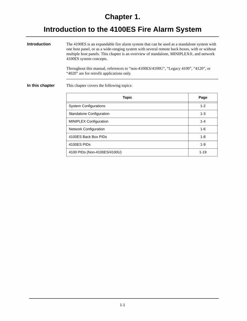
Introduction The 4100ES is an expandable fire alarm system that can be used as a standalone system with one host panel, or as a wide-ranging system with several remote back boxes, with or without multiple host panels. This chapter is an overview of standalone, MINIPLEX®, and network 4100ES system concepts.
Throughout this manual, references to “non-4100ES/4100U”, “Legacy 4100”, “4120”, or “4020” are for retrofit applications only.
In this chapter This chapter covers the following topics:
Topic Page
System Configurations 1-2
Standalone Configuration 1-3
MINIPLEX Configuration 1-4
Network Configuration 1-6
4100ES Back Box PIDs 1-8
4100ES PIDs 1-9
4100 PIDs (Non-4100ES/4100U) 1-19
1-1
Chapter 1 Introduction to the 4100ES Fire Alarm System
System Configurations
Overview The 4100ES is available as a standalone system with one host panel, or as an expansive system with several remote back boxes, with or without multiple host panels. The type of configura-tion used depends on the size of the site into which it is being installed.
The following types of configurations are offered:
Standalone. Comprised of one FACP and its assorted notification appliances, initiating devices, and signaling line circuit devices.
MINIPLEX. A standalone system plus remote transponder cabinets, which allow for additional slave modules to be used. Typically used for multi-level buildings and small multi-building applications.
Network. A multi-FACP system connected by network cards. Each panel maintains the status and control of its own circuit points while monitoring and controlling activity at other locations. Network nodes may perform similar tasks, or may be dedicated to specific functions.
This chapter outlines the fundamental concepts of each configuration
1-2

Chapter 1 Introduction to the 4100ES Fire Alarm System
Standalone Configuration
Overview The standalone version of the 4100ES is used for smaller or single-building applications. A standalone system is ideally placed into a small building that requires a limited number of notification appliances and initiating devices.
If a small building is being expanded, or if other buildings are being constructed in the same general area (as in a campus application), the standalone 4100ES can be expanded into one of the larger systems described later..
System Design The standalone 4100ES uses one FACP (one, two, or three bays) containing the following:
• Central Processing Unit (CPU)
• System Power Supply for the 4100ES FACP (Universal Power Supply for 4100 Legacy Upgrade)
• Optional slave cards
All appliances and devices are connected to that one FACP, as shown in Figure 1-1.
Figure 1-1. Standalone 4100ES System
Press ACK located under flashing indicator.Repeat operation until all events are acknowledged.Local tone will silence.
A B C
AC Power
D E F G H I
J K L M N O P Q R
'SP' ( ) , 0 :
S T U V W X Y Z /ALARMS
Fire Alarm Priority 2 AlarmSYSTEM WARNINGS
Supervisory Trouble Alarm Silenced
Emergency Operating Instructions
Alarm or Warning Condition
How to Acknowledge / View Events
How to Silence Building SignalsSystem indicator flashing. Tone On. Press Alarm Silence.
How to Reset SystemPress System Reset.Press Ack to silence tone device.
ZONE1
SIG2
AUX3
FB4
IO5
IDNet6
P7
A8
L9
NET ADDR0 DEL
Enter C/Exit
Fire AlarmAck
Priority 2Ack
SupvAck
TroubleAck
AlarmSilence
SystemReset
EventTime
Enable OnArm
Disable OffDisarm Auto Lamp
Test
MoreInfo
Menu
Previous
Next
1-3
Chapter 1 Introduction to the 4100ES Fire Alarm System
MINIPLEX Configuration
Overview The MINIPLEX version of the 4100ES Fire Alarm System, which is designed for moderately larger applications than the standalone configuration, allows up to 2000 monitor and/or control points and 2000 annunciator points to be controlled by a single FACP.
Like the standalone system, only one CPU is used. Remote Unit Interface (RUI) data and power is distributed from the host panel to remote boxes called transponder cabinets. The exact system design varies, depending on whether the system is a 4100 or a 4100ES:
• 4100ES: Transponder interface cards (TICs), located in transponder cabinets, take the RUI data and power directly from the CPU motherboard and distribute it to modules nearby, thereby expanding the system’s status from standalone to MINIPLEX.
• 4100: Remote interface cards (RICs), located in transponder cabinets, take the RUI data and power from the remote unit interface (RUI) card in the host panel and distribute it to modules nearby, thereby expanding the system’s status from standalone to MINIPLEX.
System Design The MINIPLEX 4100ES FACP must contain the following:
• CPU
• System Power Supply for the 4100ES (Universal Power Supply for 4100 Legacy Upgrade)
• 4100 only (non-4100ES/4100U): Remote unit interface (RUI) Card
• Optional slave cards
Each transponder cabinet, meanwhile, must contain a Transponder Interface Card (TIC) and any number of optional slave cards.
1-4
Chapter 1 Introduction to the 4100ES Fire Alarm System
MINIPLEX Configuration (continued)
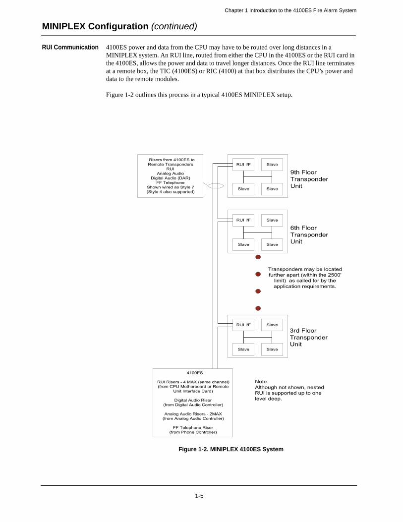
RUI Communication 4100ES power and data from the CPU may have to be routed over long distances in a MINIPLEX system. An RUI line, routed from either the CPU in the 4100ES or the RUI card in the 4100ES, allows the power and data to travel longer distances. Once the RUI line terminates at a remote box, the TIC (4100ES) or RIC (4100) at that box distributes the CPU’s power and data to the remote modules.
Figure 1-2 outlines this process in a typical 4100ES MINIPLEX setup.
Figure 1-2. MINIPLEX 4100ES System
4100ES
RUI Risers - 4 MAX (same channel)(from CPU Motherboard or Remote
Unit Interface Card)
Digital Audio Riser(from Digital Audio Controller)
Analog Audio Risers - 2MAX(from Analog Audio Controller)
FF Telephone Riser(from Phone Controller)
Transponders may be locatedfurther apart (within the 2500'
limit) as called for by theapplication requirements.
Risers from 4100ES toRemote Transponders
RUIAnalog Audio
Digital Audio (DAR)FF Telephone
Shown wired as Style 7(Style 4 also supported)
9th FloorTransponderUnit
6th FloorTransponderUnit
3rd FloorTransponderUnit
RUI I/F Slave
Slave Slave
RUI I/F Slave
Slave Slave
RUI I/F Slave
Slave Slave
Note:Although not shown, nestedRUI is supported up to onelevel deep.
1-5
Chapter 1 Introduction to the 4100ES Fire Alarm System
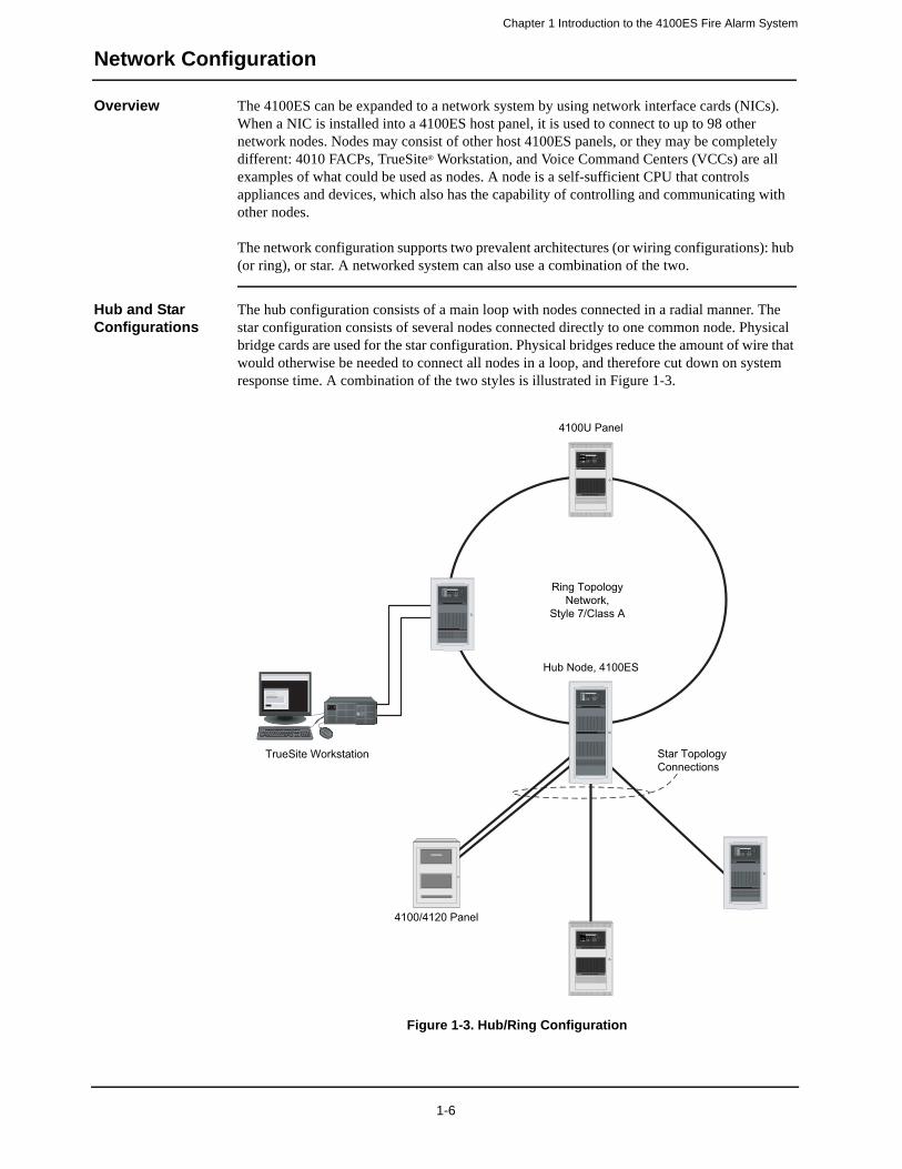
Network Configuration
Overview The 4100ES can be expanded to a network system by using network interface cards (NICs). When a NIC is installed into a 4100ES host panel, it is used to connect to up to 98 other network nodes. Nodes may consist of other host 4100ES panels, or they may be completely different: 4010 FACPs, TrueSite® Workstation, and Voice Command Centers (VCCs) are all examples of what could be used as nodes. A node is a self-sufficient CPU that controls appliances and devices, which also has the capability of controlling and communicating with other nodes.
The network configuration supports two prevalent architectures (or wiring configurations): hub (or ring), or star. A networked system can also use a combination of the two.
Hub and Star Configurations
The hub configuration consists of a main loop with nodes connected in a radial manner. The star configuration consists of several nodes connected directly to one common node. Physical bridge cards are used for the star configuration. Physical bridges reduce the amount of wire that would otherwise be needed to connect all nodes in a loop, and therefore cut down on system response time. A combination of the two styles is illustrated in Figure 1-3.
Figure 1-3. Hub/Ring Configuration
Ring Topology Network,
Style 7/Class A
Star Topology Connections
TrueSite Workstation
Hub Node, 4100ES
Fire Control
Fire Control
4100/4120 Panel
4100U Panel
1-6
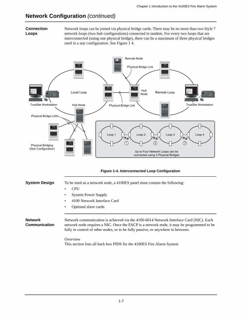
Chapter 1 Introduction to the 4100ES Fire Alarm System
Network Configuration (continued)
Connection Loops
Network loops can be joined via physical bridge cards. There may be no more than two Style 7 network loops (two hub configurations) connected in tandem. For every two loops that are interconnected (using one physical bridge), there can be a maximum of three physical bridges used in a star configuration. See Figure 1 4.
Figure 1-4. Interconnected Loop Configuration
System Design To be used as a network node, a 4100ES panel must contain the following:
• CPU
• System Power Supply
• 4100 Network Interface Card
• Optional slave cards
Network Communication
Network communication is achieved via the 4100-6014 Network Interface Card (NIC). Each network node requires a NIC. Once the FACP is a network node, it may be programmed to be fully in control of other nodes, or to be fully passive, or anywhere in between.
OverviewThis section lists all back box PIDS for the 4100ES Fire Alarm System
Remote Loop
Physical Bridge Link
Local Loop
Physical Bridging(Star Configuration)
TrueSite Workstation
Physical Bridge Link
Physical Bridge Links
Hub Node
HubNode
Remote Node
Fire ControlFire Control
TrueSite Workstation
Fire Control
Fire Control Fire Control
Fire Control
1 2 3
Up to Four Network Loops can be connected using 3 Physical Bridges
Loop 1 Loop 2 Loop 3 Loop 4
1-7

Chapter 1 Introduction to the 4100ES Fire Alarm System
4100ES Back Box PIDs
Overview This section lists all back box PIDS for the 4100ES Fire Alarm System.
4100ES Back Boxes
The 4100ES Back Boxes are shipped as follows:
Box and Door Enclosures:
2975-9441 One Bay Back Box, Glass Door & Dress Panels – Red (743-934)
2975-9442 Two-Bay Back Box, Glass Door & Dress Panel – Red (743-935)
2975-9443 Three-Bay Back Box, Glass Door & Dress Panel – Red (743-936)
2975-9444 One-Bay Back Box, Glass Door & Dress Panel – Platinum (743-937)
2975-9445 Two-Bay Back Box, Glass Door & Dress Panel – Platinum (743-938)
2975-9446 Three-Bay Back Box, Glass Door & Dress Panel – Platinum (743-939)
2975-9447 One-Bay Back Box, Solid Door & Dress Panel – Red (743-940)
2975-9448 Two-Bay Back Box, Solid Door & Dress Panel – Red (743-941)
2975-9449 Three-Bay Back Box, Solid Door & Dress Panel – Red (743-942)
2975-9450 One-Bay Back Box, Solid Door & Dress Panel – Platinum (743-943)
2975-9451 Two-Bay Back Box, Solid Door & Dress Panel – Platinum (743-944)
2975-9452 Three-Bay Back Box, Solid Door & Dress Panel – Platinum (743-945)
Doors and Dress Panels:
4100-2104 One-Bay Glass Door & Dress Panel - Platinum (743-950)
4100-2105 Two-Bay Glass Door & Dress Panel - Platinum (743-951)
4100-2106 Three-Bay Glass Door & Dress Panel - Platinum (743-952)
4100-2114 One-Bay Solid Door & Dress Panel - Platinum (743-953)
4100-2115 Two-Bay Solid Door & Dress Panel - Platinum (743-954)
4100-2116 Three-Bay Solid Door & Dress Panel - Platinum (743-955)
4100-2124 One-Bay Glass Door & Dress Panel - Red (743-956)
4100-2125 Two-Bay Glass Door & Dress Panel - Red (743-957)
4100-2126 Three-Bay Glass Door & Dress Panel - Red (743-958)
4100-2134 One-Bay Solid Door & Dress Panel - Red (743-959)
4100-2135 Two-Bay Solid Door & Dress Panel - Red (743-960)
4100-2136 Three-Bay Solid Door & Dress Panel - Red (743-961)
Back Boxes by themselves:
2975-9407 One-Bay Red Box (742-414)
2975-9408 Two-Bay Red Box (742-416)
2975-9409 Three-Bay Red Box (742-418)
2975-9438 One-Bay Back Box – Platinum (743-946)
2975-9439 Two-Bay Back Box – Platinum (743-947)
2975-9440 Three-Bay Back Box – Platinum (743-948)
Accessories:
2975-9812 Red Trim Band (742-638)
2975-9813 Semi-Flush Trim Band – Platinum (743-949)
1-8
Chapter 1 Introduction to the 4100ES Fire Alarm System
4100ES PIDs
Overview This section lists the PIDs (model numbers) that are supported by the 4100ES Fire Alarm System. There are two basic types of PIDs listed here:
• PIDs denoting standard installations, such as host panels containing multiple, already functioning modules
• PIDs denoting individual modules or back boxes
- offered as after-market product for standard installations- offered as options or aftermarket product for configured installations
The 4100ES features either a 2x40 alphanumeric display or the multi-line LCD of the Flexible User Interface.
Note: Software-related PIDs, such as vertical market software packages and programmer options, are not listed in this book.
Basic Control Panels (United States)
This section lists the basic control panels available in the U.S.
• 4100-9111 2x40 Master Controller – Domestic (742-830)
4100-9114 Flexible User Interface Master Controller – Domestic (743-201)(120 VAC 60 HZ), Display, CPU Card, System Power Supply that includes 250 Address-able/Analog Points, 3 Class A/B NACs, 1 IDNet channel, 24 VDC Aux. Relay, 24 VDC Aux. Power Tap, 50 Ah (Max) Battery Charger and 9 A Total Signal/Card Power.
• 4100-9121 2x40 Redundant Master Controller – Domestic (742-729)
(120 VAC 60 HZ), Displays (2), CPU Cards (2), System Power Supply that includes 250 Addressable/Analog Points, 3 Class A/B NACs, 1 IDNet channel, 24 VDC Aux. Relay, 24 VDC Aux. Power Tap, 50 Ah (Max) Battery Charger and 9 A Total Signal/Card Power. Occupies two bays.
• 4100-9122 Flexible User Interface Redundant Master Controller – Domestic (743-239)
(120 VAC 60 HZ), Display, CPU Cards (2), System Power Supply that includes 250 Addressable/Analog Points, 3 Class A/B NACs, 1 IDNet channel, 24 VDC Aux. Relay, 24 VDC Aux. Power Tap, 50 Ah (Max) Battery Charger and 9 A Total Signal/Card Power. Occupies two bays.
• 4100-9131 Master Controller – Domestic (742-844)
(120 VAC 60 HZ), No Display, CPU Card, System Power Supply that includes 250 Addressable/Analog Points, 3 Class A/B NACs, 1 IDNet channel, 24 VDC Aux. Relay, 24 VDC Aux. Power Tap, 50 Ah (Max) Battery Charger and 9 A Total Signal/Card Power.
Basic Control Panels (Canada)
This section lists the basic control panels available in Canada. Both panels have the same properties.
• 4100-9112 2x40 Master Controller – Canadian English (742-831)/ 4100-9115 Flexible User Interface Master Controller – Canadian English (743-202)(120 VAC 60 HZ), Display, CPU Card, System Power Supply that includes 250 Address-able/Analog Points, 3 Class A/B NACs, 1 IDNet channel, 24 VDC Aux. Relay, 24 VDC Aux. Power Tap, 50 Ah (Max) Battery Charger, Battery Cutout Circuit, and 9 A Total Sig-nal/Card Power.
Continued on next page
1-9
Chapter 1 Introduction to the 4100ES Fire Alarm System
4100ES PIDs (continued)
Basic Control Panels (Canada)
• 4100-9113 2x40 Redundant Master Controller – Canadian French (742-832)/4100-9116 Flexible User Interface Redundant Master Controller – Canadian French (743-203)(120 VAC 60 HZ), Display, CPU Card, System Power Supply that includes 250 Address-able/Analog Points, 3 Class A/B NACs, 1 IDNet channel, 24 VDC Aux. Relay, 24 VDC Aux. Power Tap, 50 Ah (Max) Battery Charger, Battery Cutout Circuit, and 9 A Total Sig-nal/Card Power.
• 4100-9132 Master Controller – Canadian English (742-845)(120 VAC 60 HZ), No Display, CPU Card, System Power Supply that includes 250 Addressable/Analog Points, 3 Class A/B NACs, 1 IDNet channel, 24 VDC Aux. Relay, 24 VDC Aux. Power Tap, 50 Ah (Max) Battery Charger, Battery Cutout Circuit, and 9 A Total Signal/Card Power.
• 4100-9133 Master Controller – Canadian French (742-846)(120 VAC 60 HZ), No Display, CPU Card, System Power Supply that includes 250 Addressable/Analog Points, 3 Class A/B NACs, 1 IDNet channel, 24 VDC Aux. Relay, 24 VDC Aux. Power Tap, 50 Ah (Max) Battery Charger, Battery Cutout Circuit, and 9 A Total Signal/Card Power.
Basic Control Panels (International)
• 4100-9211 2x40 Master Controller – International (742-848)/ 4100-9212 Master Controller – 220/240 V (743-204) 4100-9214 Master Controller – China 220/240V (743-765) (220/230/240 VAC 50/60 HZ), Display, CPU Card, System Power Supply that includes 250 Addressable/Analog Points, 3 Class A/B NACs, 1 IDNet channel, 24 VDC Aux. Relay, 24 VDC Aux. Power Tap, 50 Ah (Max) Battery Charger, and 9 A Total Signal/Card Power.
• 4100-9213 Flexible User Interface Master Controller – 220/240 V (743-333)(120 VAC 60 HZ) Display, CPU Card, System Power Supply that includes 250 Address-able/Analog Points, 3 Class A/B NACs, 1 IDNet channel, 24 V Aux. Relay, 24 VDC Aux. Power Tap, 50 Ah (Max) Battery Charger, and 9 A Total Signal/Card Power
• 4100-9230 Master Controller – International (742-849)(220/230/240 VAC 50/60 HZ), No Display, CPU Card, System Power Supply that includes 250 Addressable/Analog Points, 3 Class A/B NACs, 1 IDNet channel, 24 VDC Aux. Relay,
24 VDC Aux. Power Tap, 50 Ah (Max) Battery Charger, and 9 A Total Signal/Card Power.
Transponders This section lists the two transponder cabinets, both of which include an expansion bay with a power distribution interface (PDI) and a transponder interface card (TIC).
• 4100-9600 Basic Transponder (742-866). Includes basic TIC.
• 4100-9601 Local Mode Transponder (742-867). Includes local mode TIC.
Remote Annunciator
• 4100-9610 Remote Annunciator (742-868). Includes an expansion bay with a power distribution interface (PDI) and a transponder interface card (TIC).
• 4100-9611 Remote Annunciator (743-081). Includes an expansion bay with a power distribution interface (PDI) and a transponder interface card (TIC).
1-10

Chapter 1 Introduction to the 4100ES Fire Alarm System
4100ES PIDs (continued)
Remote Display Assemblies
• 4100-9401 Red Flexible User Interface Remote Display Assembly - Domestic (743-187). Includes a remote box with a Flexible User Interface display and a TIC (566-692).
• 4100-9402 Beige Flexible User Interface Remote Display Assembly - Domestic (743-188). Includes a remote box with a Flexible User Interface display and a TIC (566-692).
• 4100-9421 Red Flexible User Interface Remote Display Assembly – Canadian French (743-189). Includes a remote box with a Flexible User Interface display and a TIC (566-692).
• 4100-9422 Beige Flexible User Interface Remote Display Assembly – Canadian French (743-190). Includes a remote box with a Flexible User Interface display and a TIC (566-692).
• 4100-9441 Red Flexible User Interface Remote Display Assembly – International (743-191). Includes a remote box with a Flexible User Interface display and a TIC (566-692).
• 4100-9442 Beige Flexible User Interface Remote Display Assembly – International (743-192). Includes a remote box with a Flexible User Interface display and a TIC (566-692).
Basic Audio Selections
This section lists the two audio cabinets, both of which include an audio expansion bay with a power distribution interface (PDI), audio controller board, and a microphone module.
• 4100-9620 Basic Audio with Microphone – Analog (742-869)
• 4100-9601 Basic Audio with Microphone – Digital (742-870)
Utility Cabinets This section lists the two utility cabinets, which contain mounting rails for bays and mounting plates for 2120 modules.
• 4100-9642 Two-Bay Utility Cabinet Kit (for 2120 Equipment) (742-871). Includes two-bay mounting rails and two 4100 (non-4100ES/4100U) expansion bays.
• 4100-9643 Three-Bay Utility Cabinet Kit (for 2120 Equipment) (742-872). Includes three-bay mounting rails and three 4100 (non-4100ES/4100U) expansion bays.
Note: The rack-mount option is not Listed for security applications and cannot be used to pro-vide monitoring of security parts.
Master Controller Upgrade Kits
Upgrade kits are used for retrofitting newer modules into old-style systems.
• 4100-7150 Master Controller Upgrade with 2x40 Display (old 4100 to Rev 10 or higher) (742-592)
• 4100-7151 Master Controller Upgrade with No Display (old 4100 to Rev 10 or higher) (742-394)
• 4100-7152 Master Controller Upgrade with 2X40 Display, operator interface and power supply (old 4100 to Rev 10 or higher) (742-922)
• 4100-7153 Flexible User Interface Display Upgrade (4100ES with 2x40 display to Flexible User Interface display) (743-240)
• 4100-7154 Master Controller Upgrade with Flexible User Interface Display (old 4100 to Rev 10 or higher) (743-241)
• 4100-7158 NXP Master Controller Upgrade w/o Display (Legacy 4100 to Rev 13 or higher) (743-777
• 4100-9833 Master Controller Upgrade with 2x40 Display in One-Bay Beige Enclosure (4020) (742-804)
Note: The rack-mount option is not Listed for security applications and cannot be used to pro-vide monitoring of security parts.
1-11
Chapter 1 Introduction to the 4100ES Fire Alarm System
4100ES PIDs (continued)
Rack Mount Kits • 4100-2140 Bay Mounting Kit (742-741)
• 4100-2144 PDM Mounting Kit (742-547)
Note: The rack-mount option is not Listed for security applications and cannot be used to pro-vide monitoring of security parts.
Power Distribution Modules
• 4100-0634 Power Distribution Module 120 V (742-396)• 4100-0635 Power Distribution Module 220/230/240 V (742-513)
Expansion Bays • 4100-2300 Non-Audio Expansion Bay (742-839)• 4100-2301 Expansion Bay Upgrade Kit (742-602)• 4100-2320 Audio Expansion Bay (742-873)
Expansion Battery Chargers for Basic FACPs
The expansion battery chargers listed here are used with the standard control panels listed above.
• 4081-9306 External 120 V Battery Cabinet with Charger for 110 Ah Batteries; Red (637-029)
• 4081-9308 External 220-240 V Battery Cabinet with Charger for 110 Ah Batteries; Red (637-030)
Communication Modules
The following communication modules can be added on to 4100ES systems.• 4100-3101 IDNet Card – 250 Devices (742-476) • 4100-3102 MAPNET II Interface Module (742-696)• 4100-3103 MAPNET Isolator Module (742-725)• 4100-3104 IDNet Card – 127 Devices (742-817)• 4100-3105 IDNet Card – 64 Devices (742-818)• 4100-3107 IDNet + Quad Iso -250 devices (743-561)• 4100-6014 Network Interface Card (NIC) (742-701)• 4100-6030 Service Modem Module (742-584)• 4100-6031 City Card with Disconnect (742-403)• 4100-6032 City Card without Disconnect (742-404)• 4100-6033 Alarm Relay Card (742-402)• 4100-6034 Tamper Switch with IDNet IAM (742-648)• 4100-6036 Physical Bridge (Style 4) (742-702)• 4100-6037 Physical Bridge (Style 7) (742-703)• 4100-6038 Dual RS-232 Interface Card (742-704)• 4100-6039 Modem Bridge (2120) (742-705)• 4100-6041 DC Powered FSK Modem (2120) (742-707)• 4100-6042 Communication Line Repeater (2120) (742-708)• 4100-6043 RS-232/ DC Comm Converter (2120) (742-709)• 4100-6044 DC Comm/ RS-232 Converter (2120) (742-710)• 4100-6045 Decoder Module (742-711)• 4100-6047 Building Interface Card (743-872)• 4100-6048 VESDA Interface Kit (742-714)• 4100-6052 DACT (742-700)• 4100-6054 Fiber-Optic Line Driver (2120) (742-715)• 4100-6055 Modem Media Card (742-841)• 4100-6056 Wired Media Card (742-619)• 4100-6057 Fiber-Optic Media Card (742-620)• 4100-6058 Style 7 Interface Module (DC Comm – 2120) (742-604)• 4100-6059 Decoder Module (2120) (742-596)• 4100-6062 TFX Interface (743-278)• 4100-6065 BMUX Communication Module (743-645)• 4100-6069 BACpac Ethernet (743-747)
1-12

Chapter 1 Introduction to the 4100ES Fire Alarm System
4100ES PIDs (continued)
Power Supplies The power supplies listed below can be used with 4100ES systems.• 4100-5101 Expansion Power Supply (XPS) (120 VAC) (60 Hz) (742-383)
• 4100-5102 Expansion Power Supply (XPS) (220/230/240 VAC) (50/60 Hz) (742-384)
• 4100-5103 Expansion Power Supply (XPS) (120 VAC) (60 Hz) (Canada) (742-385)
• 4100-5111 System Power Supply (SPS) (120 VAC) (60 Hz) (742-631)
• 4100-5112 System Power Supply (SPS) (220/230/240 VAC) (50/60 Hz) (742-632)
• 4100-5113 System Power Supply (SPS) (120 VAC) (60 Hz) (Canada) (742-633)
• 4100-5115 Expansion NAC Module (XNAC) (742-386)
• 4100-5120 TrueAlert Power Supply (TPS) (120 VAC) (742-659)
• 4100-5121 TrueAlert Power Supply (TPS) (120 VAC) (Canada) (742-660)
• 4100-5122 TrueAlert Power Supply (TPS) (220/230/240 VAC) (742-661)
• 4100-5124 TrueAlert Class A Adapter Module (742-662)
• 4100-5125 Remote Power Supply (RPS) (120 VAC) (742-628)
• 4100-5126 Remote Power Supply (RPS) (120 VAC) (Canada) (742-629)
• 4100-5127 Remote Power Supply (RPS) (220/230/240 VAC) (742-300)
• 4100-5152 12 V, 2 A Power Option (742-718)
• 4100-5153 13 A Utility Power Supply (24 VDC/120 VAC) (2120) (742-719)
• 4100-5154 13 A Utility Power Supply (24 VDC/240 VAC) (2120) (742-720)
• 4100-5155 8 A Expansion Power Supply with 4 A Charger 120/240 VAC (2120) (742-517)
• 4100-0156 8 VDC Converter (742-816)
Signaling Modules
The signaling modules listed below can be used with 4100ES systems.
• 4100-5005 8-Zone Module (Class B) (742-655)
• 4100-5015 8-Zone Module (Class A) (742-721)
• 4100-3201 4-Relay Module (2 A) (742-722)
• 4100-3202 4-Relay Module (10 A) (742-723)
• 4100-3203 8-Relay Module (3 A) (742-724)
• 4100-3204 4-Point Relay Module (2 A) (742-948)
• 4100-3206 8-Point Relay Module (3 A) (742-949)
Annunciator Modules
The following annunciator modules are available for the 4100ES.• 4100-1279 2-inch (51-mm) Blank Display Module (742-519)• 4100-1280 8-Switch/8-LED Display Card (Red LEDs) (742-509)• 4100-1281 8-Switch/8-LED Display Card (Yellow LEDs) (742-508)• 4100-1282 8-Switch/16-LED Display Card (1 red / 1 yellow LED per switch) (742-408)• 4100-1283 8-Switch/16-LED Display Card (2 yellow LEDs per switch) (742-409)• 4100-1284 8-Switch/16-LED Display Card (1 red / 1 green LED per switch) (742-407)• 4100-1285 16-Switch/16-LED Display Card (Red LEDs) (742-507)• 4100-1286 Hands Off Auto (HOA) Switch Display Card (742-514)• 4100-1287 24-Switch/24-LED Display Card (Red LEDs) (742-506)• 4100-1288 LED/Switch Controller Card (742-410)• 4100-1289 Expansion LED/Switch Controller Card (No mounting plate) (742-626)• 4100-1290 24-Point Graphic I/O Module (742-726)• 4100-1291 Remote Unit Interface Card (742-727)• 4100-1292 Remote Command Center (742-737)• 4100-1293 Panel-Mounted Printer (742-739)• 4100-1294 LED/Switch Slide-In Label Kit (for up to 3 Bays) (742-863)• 4100-1295 HOA Module (No Text) with 24 Switches and 24 Red LEDs (742-874)
1-13
Chapter 1 Introduction to the 4100ES Fire Alarm System
4100ES PIDs (continued)
Transponders and Transponder Components
The following is a list of transponder cabinets and components for the 4100ES.
• 4100-9600 Basic Transponder (Expansion Bay with PDI and Basic TIC) (742-866)
• 4100-9601 Local Mode Transponder (Expansion Bay with PDI and Local Mode TIC) (742-867)
• 4100-0620 Basic Transponder Interface Card (TIC) (742-520)
• 4100-0621 Analog Audio Riser Module (742-534)
• 4100-0622 Digital Audio Riser Module (742-535)
• 4100-0625 Local Mode TIC (742-521)
• 4100-0632 Terminal Block Utility Module (742-695)
• 4100-0633 Transponder Cabinet Tamper Switch (742-738)
• 4100-1341 MCC Digital Audio Riser Module (743-850)
Audio Operator Interfaces
The following modules are used only with the 4100U and 4100ES systems.
• 4100-1252 Audio Operator Interface – 1 Channel (742-798)
• 4100-1253 Audio Operator Interface – 1.5 Channel (742-801)
• 4100-1254 Audio Operator Interface – 2 Channel (742-799)
• 4100-1255 Audio Operator Interface – 3-8 Channel (742-800)
Audio Controller Boards
The following audio controller boards are used with the audio operator interface.
• 4100-1210 Audio Controller Board – Analog, 1.5 Channels (742-517)
• 4100-1211 Audio Controller Board – Digital (742-387)
• 4100-1311 Audio Controller Board – Digital (743-446)
Telephones/Microphones
The following phone and microphone assemblies are used with audio operator interfaces.
• 4100-1270 Master Telephone with Phone Card and 3 NACs (742-865)
• 4100-1271 Remote Master Telephone (742-597)
• 4100-1243 Microphone (742-523)
• 4100-1244 Remote Microphone (742-821)
• 4100-1265 Degraded Fail-Safe Mode Microphone Pre-Amp (Master – 743-238)
• 4100-1269 Degraded Fail-Safe Mode Microphone Pre-Amp (Slave – 743-306)
Additional Audio Modules
Optional modules for the 4100ES audio system are listed below.
• 4100-0623 Network Audio Interface Module (742-522)
• 4100-1240 Aux Audio Input Board (742-388)
• 4100-1241 Audio Message Memory Expansion Module, 8 Minute (742-518)
• 4100-1242 Audio Message Memory Expansion Module, 32 Minute (742-393)
• 4100-1272 Telephone Expansion Card (742-600)
• 4100-1273 Class A Telephone Adapter Module (742-599)
• 4100-1274 Microphone Mux Module (743-808)
1-14

Chapter 1 Introduction to the 4100ES Fire Alarm System
4100ES PIDs (continued)
Common Audio Options
• 4100-1245 Flex 50 Expansion NAC Board with 3 Class B NACs (742-540)
• 4100-1246 Flex 50 Class A Adapter (Converts 3 on-board NACs to Class A) (742-539)
• 4100-1248 100 Watt Expansion NAC Board with 6 Class B NACs (742-524)
• 4100-1249 100 Watt Class A Adapter (Converts 6 on-board NACs to Class A) (742-543)
• 4100-1259 Constant Supervision NAC 25 VRMS with 3 Class A/B Constant Supervision NACs (Converts 3 on-board NACs to Constant Supervision) (743-163)
• 4100-1260 Constant Supervision NAC 70 VRMS with 3 Class A/B Constant Supervision NACs (Converts 3 on-board NACs to Constant Supervision) (743-164)
• 4100-1266 Expansion Signal Card Expansion NAC Board with 3 Class B NACs (743-302)
• 4100-1267 Expansion Signal Card Class A Adapter (Converts 3 on-board NACs to Class A (743-303)
• 4100-1268 Expansion Signal Card Constant Supervision NAC Adapter, 25 or 70 VRMS with 3 Class A/B Constant Supervision NACs (Converts 3 on-board NACs to Constant Supervision) (743-304)
• 4100-5116 Expansion Signal Card with 3 Class B NACs (743-159)
Amplifiers Note: The following amplifiers are used only in the 4100U and 4100ES systems and are not compatible with the Constant Supervision NAC (CSNAC) option.
100 W Analog Amplifiers:
• 4100-1214 Amp – 120 VAC, 25 VRMS (742-550)
• 4100-1215 Amp – 120 VAC, 70 VRMS (742-551)
• 4100-1216 Amp – 120 VAC, 25 VRMS – Canada (742-552)
• 4100-1217 Amp – 120 VAC, 70 VRMS – Canada (742-553)
• 4100-1218 Amp – 220/230/240 VAC, 25 VRMS (742-554)
• 4100-1219 Amp – 220/230/240 VAC, 70 VRMS (742-555)
• 4100-1220 Backup Amp – 120 VAC, 25 VRMS (742-550)
• 4100-1221 Backup Amp – 120 VAC, 70 VRMS (742-551)
• 4100-1222 Backup Amp – 120 VAC, 25 VRMS – Canada (742-552)
• 4100-1223 Backup Amp – 120 VAC, 70 VRMS – Canada (742-553)
• 4100-1224 Backup Amp – 220/230/240 VAC, 25 VRMS (742-554)
• 4100-1225 Backup Amp – 220/230/240 VAC, 70 VRMS (742-555)
100 W Digital Amplifiers (except for 4100-1230 & -1236 [95 W]):
• 4100-1228 Amp – 120 VAC, 25 VRMS (742-544)
• 4100-1229 Amp – 120 VAC, 70 VRMS (742-545)
• 4100-1230 Amp – 120 VAC, 25 VRMS – Canada (742-546)
• 4100-1231 Amp – 120 VAC, 70 VRMS – Canada (742-547)
• 4100-1232 Amp – 220/230/240 VAC, 25 VRMS (742-548)
• 4100-1233 Amp – 220/230/240 VAC, 70 VRMS (742-549)
• 4100-1234 Backup Amp – 120 VAC, 25 VRMS (742-544)
• 4100-1235 Backup Amp – 120 VAC, 70 VRMS (742-545)
• 4100-1236 Backup Amp – 120 VAC, 25 VRMS – Canada (742-546)
• 4100-1237 Backup Amp – 120 VAC, 70 VRMS – Canada (742-547)
• 4100-1238 Backup Amp – 220/230/240 VAC, 25 VRMS (742-548)
• 4100-1239 Backup Amp – 220/230/240 VAC, 70 VRMS (742-549)
Continued on next page
1-15
Chapter 1 Introduction to the 4100ES Fire Alarm System
4100ES PIDs (continued)
Amplifiers Analog Flex Amplifiers:
• 4100-1212 Analog Flex 50 W Amp – 25 VRMS (742-794)
• 4100-1213 Analog Flex 50 W Amp – 70 VRMS (742-795)
• 4100-1261 Analog Flex 35 W Amp – 25 VRMS (743-001)
• 4100-1262 Analog Flex 35 W Amp – 70 VRMS (742-002)
Digital Flex Amplifiers:
• 4100-1226 Digital Flex 50 W Amp – 25 VRMS (742-796)
• 4100-1227 Digital Flex 50 W Amp – 70 VRMS (742-797)
• 4100-1263 Digital Flex 35 W Amp – 25 VRMS (743-003)
• 4100-1264 Digital Flex 35 W Amp – 70 VRMS (743-004)
Note: The following amplifiers are only used in the 4100U and 4100ES systems and are compatible with the Constant Supervision NAC (CSNAC) option and 4100U Master Firmware Revision 11.08 or later.
100 W Analog Amplifiers:
• 4100-1314 Amp – 120 VAC, 25 VRMS (743-438)
• 4100-1315 Amp – 120 VAC, 70 VRMS (743-439)
• 4100-1316 Amp – 120 VAC, 25 VRMS – Canada (743-440)
• 4100-1317 Amp – 120 VAC, 70 VRMS – Canada (743-441)
• 4100-1318 Amp – 220/230/240 VAC, 25 VRMS (743-442)
• 4100-1319 Amp – 220/230/240 VAC, 70 VRMS (743-443)
• 4100-1320 Backup Amp – 120 VAC, 25 VRMS (743-438)
• 4100-1321 Backup Amp – 120 VAC, 70 VRMS (743-439)
• 4100-1322 Backup Amp – 120 VAC, 25 VRMS – Canada (743-440)
• 4100-1323 Backup Amp – 120 VAC, 70 VRMS – Canada (743-441)
• 4100-1324 Backup Amp – 220/230/240 VAC, 25 VRMS (743-442)
• 4100-1325 Backup Amp – 220/230/240 VAC, 70 VRMS (743-443)
100 W Digital Amplifiers:
• 4100-1328 Amp – 120 VAC, 25 VRMS (743-449)
• 4100-1329 Amp – 120 VAC, 70 VRMS (743-450)
• 4100-1330 Amp – 120 VAC, 25 VRMS – Canada (743-451)
• 4100-1331 Amp – 120 VAC, 70 VRMS – Canada (743-452)
• 4100-1332 Amp – 220/230/240 VAC, 25 VRMS (743-453)
• 4100-1333 Amp – 220/230/240 VAC, 70 VRMS (743-454)
• 4100-1334 Backup Amp – 120 VAC, 25 VRMS (743-449)
• 4100-1335 Backup Amp – 120 VAC, 70 VRMS (743-450)
• 4100-1336 Backup Amp – 120 VAC, 25 VRMS – Canada (743-451)
• 4100-1337 Backup Amp – 120 VAC, 70 VRMS – Canada (743-452)
• 4100-1338 Backup Amp – 220/230/240 VAC, 25 VRMS (743-453)
• 4100-1339 Backup Amp – 220/230/240 VAC, 70 VRMS (743-454)
Continued on next page
1-16
Chapter 1 Introduction to the 4100ES Fire Alarm System
4100ES PIDs (continued)
Amplifiers Analog Flex Amplifiers:
• 4100-1312 Analog Flex 50 W Amp – 25 VRMS (743-436)
• 4100-1313 Analog Flex 50 W Amp – 70 VRMS (743-437)
• 4100-1361 Analog Flex 35 W Amp – 25 VRMS (743-444)
• 4100-1362 Analog Flex 35 W Amp – 70 VRMS (743-445)
Digital Flex Amplifiers:
• 4100-1326 Digital Flex 50 W Amp – 25 VRMS (743-447)
• 4100-1327 Digital Flex 50 W Amp – 70 VRMS (743-448)
• 4100-1363 Digital Flex 35 W Amp – 25 VRMS (743-455)
• 4100-1364 Digital Flex 35 W Amp – 70 VRMS (743-456)
Miscellaneous Modules
The following modules are for 4100ES systems.
• 4100-0650 Battery Shelf (for 50 Ah batteries) (742-840)
• 4100-0640 Memory Add-On Module for Flexible User Interface (743-279)
• 4100-5128 Battery Distribution Terminal Module (742-843)
• 4100-9854 4100U/4100ES Module Legacy Bay Mounting Kit (743-856)
1-17

Chapter 1 Introduction to the 4100ES Fire Alarm System
4100 PIDs (Non-4100ES/4100U)
Overview This section lists the 4100 (non-4100ES/4100U) PIDs that are supported by the 4100ES Fire Alarm System (in retrofit applications). There are two basic types of PIDs listed here:
• PIDs denoting standard installations, such as host panels containing multiple, already functioning modules
• PIDs denoting individual modules or back boxes
- offered as after-market product for standard installations- offered as options or aftermarket product for configured installations
Note: Software-related PIDs, such as vertical market software packages and programmer options, are not listed in this book.
System Types and Options
There are six standard types of 4100 control panels used with the 4100. A PID identifies each system type. These PIDs are combined with the more specific PIDs listed after this topic to meet the requirements of custom installations.
• 4100-8001 Fire Alarm Control Panel
• 4100-8002 Remote Annunciator Panel
• 4100-8010 MINIPLEX Fire Alarm Control Panel
• 4100-8019 MINIPLEX Fire Alarm Control Panel with Transponder
• 4100-8201 Fire Alarm Control Panel with Audio
• 4100-8210 MINIPLEX Fire Alarm Control Panel with Audio
• 4100-8901/8909 Add-On to Existing System or Annunciator
• 4100-6050/6051 Power Limited Panel/Non-Power Limited Panel
Master Controller Option Module
4100-6001 240 VAC Controller Power Input
1-18
Chapter 1 Introduction to the 4100ES Fire Alarm System
4100 PIDs (Non-4100ES/4100U) (continued)
NAC Modules Notification appliance circuit (NAC) modules are listed below.
•
• 4100-4001 2-Circuit (Style Y)
• 4100-4011 2-Circuit (Style Z)
• 4100-4321 6-Circuit (Style Y)
• 4100-4331 6-Circuit (Style Z)
IDC Modules Initiating device circuit (IDC) modules are listed below.See 579-832 revision G for 2-Wire Detector Compatibility Chart.
• 4100-5004 8-Zone (Style B)
• 4100-5014 8-Zone (Style D)
Optional Modules Miscellaneous optional modules are listed below.
• 4100-0104 Additional Battery Charger (120 V)
• 4100-0105 5 A Power Supply (120 V; Non-Power Limited)
• 4100-0108 Expansion 8 A Power Supply (Non-Power Limited)
• 4100-0110 MAPNET II Addressable Module
• 4100-0111 MAPNET II Isolator Module
• 4100-0113 Dual RS-232 Module
• 4100-0114 Additional Battery Charger (240 V)
• 4100-0115 5 A Power Supply (240 V; Non-Power Limited)
• 4100-0117 MINIPLEX 8 A Remote Power Supply (Power Limited)
• 4100-0118 8 A Power Supply (240 V; Non-Power Limited)
• 4100-0119 2 A Converter (12 VDC; Non-Power Limited)
• 4100-0123 2120 Communications Module (Style 7)
• 4100-0124 Enhanced Charger Package
• 4100-0129 25.5 V Limiter Module
• 4100-0136 Decoder Module
• 4100-0137 RS-232 Module for 2120 Communications (Style 7)
• 4100-0139 Service Modem
• 4100-0153 Contact Closure DACT
• 4100-0154 VESDA Interface (Aftermarket Only)
• 4100-0155 Serial DACT
• 4100-0304 Remote Unit Interface (RUI) Module (Style 7)
• 4100-0451 Panel-Mounted Printer
• 4100-0540 4-20 mA ZAM Modules (2 per plate)
• 4100-1108 8 A Power Supply (120 VAC; Power Limited)
Auxiliary Relay Controls
The following modules are auxiliary relay controls.
• 4100-3001 4-Relay, 2 A (with feedback)
• 4100-3002 4-Relay, 10 A (with feedback)
• 4100-3003 8-Relay, 3 A (with feedback)
1-19

Chapter 1 Introduction to the 4100ES Fire Alarm System
4100 PIDs (Non-4100ES/4100U) (continued)
Audio Controllers and Amplifiers
The following modules can be used in 4100ES Upgrade/Retrofit applications, but cannot be used with 4100ES audio modules.
• 4100-0210 Single-Channel Audio Controller Board
• 4100-0211 Dual-Channel Audio Controller Board
• 4100-0212 Triple-Channel Audio Controller Board
• 4100-0201 25 VRMS/25 W Audio Amplifier (no Power Supply; Power Limited)
• 4100-0202 25 VRMS/Dual 25 W Audio Amplifier (with Power Supply; Power Limited)
• 4100-1203 25 VRMS/100 W Audio Amplifier (120 VAC; Power Limited)
• 4100-0203 25 VRMS/100 W Audio Amplifier (120 VAC; Non-Power Limited)
• 4100-0213 25 VRMS/100 W Audio Amplifier (240 VAC; Non-Power Limited)
• 4100-0207 70 VRMS/100 W Audio Amplifier (120 VAC; Non-Power Limited)
• 4100-0217 70 VRMS/100 W Audio Amplifier (240 VAC; Non-Power Limited)
• 4100-1207 70 VRMS/90 W Audio Amplifier (120 VAC; Power Limited)
Audio Options The following options can be used in 4100ES Retrofit/Upgrade systems with 4100 Back Boxes.
• 4100-0204 Microphone and Enclosure
• 4100-0205 Master Telephone
• 4100-0206 Redundant Tone Generator
• 4100-0215 Phone Riser Terminal Block
Annunciation Modules
• 4100-0301 64/64 LED/Switch Controller
• 4100-0302 24-Point I/O Graphic Interface
• 4100-0401 8-LED Display Card (Red Led)
• 4100-0402 16-Point Display Card (Red/Yellow LEDs)
• 4100-0403 8-Switch/8-LED Display Card (Momentary switches; red LEDs)
• 4100-0404 8-Switch/16-LED Display Card (Maintained switches; one red and one green LED per switch)
• 4100-0405 8-Switch/16-LED Display Card (Maintained switches; one red and one yellow LED per switch)
• 4100-0408 8-Switch/8-LED Annunciator Control Switch Module
• 4100-0450 Remote Panel LCD
1-20
Chapter 1 Introduction to the 4100ES Fire Alarm System
4100 PIDs (Non-4100ES/4100U) (continued)
Miscellaneous Modules
• 4100-0133 Tamper Switch
• 4100-1010 External Battery Power and Charger
Network Modules The following modules are intended to be used in a networked 4100 system.
• 4120-6014 Modular Interface Board
• 4120-6023 Physical Bridge (Style 4)
• 4120-6024 Physical Bridge (Style 7)
• 4120-0142 Wired Media Card
• 4120-0143 Fiber-Optic Media Card
• 4120-0144 Modem Media Card
• 4120-0156 8 VDC Module (provides 3 A from 28 V tap)
System Accessories
• 2080-9047 DACT Communication Cable (14 feet [4 meters]) (733-913)
• 2081-9031 Potted Module for PVCS (740-688)
• 2081-9272 Batteries (6.2 Ah) (112-112)*
• 2081-9274 Batteries (10 Ah) (112-113)*
• 2081-9275 Batteries (18.8 Ah) (112-046)*
• 2081-9276 Batteries (33 Ah) (112-053)*
• 2081-9279 Batteries (110 Ah) (112-123)*
• 2081-9287 Batteries (25 Ah) (112-134)*
• 2081-9288 Batteries (12.7 Ah) (112-133)*
• 2081-9296 Batteries (50 Ah) (112-136)*
• 4190-9803 Replacement Paper for 4100-0451 Panel-Mounted Printer (473-019)
*Or equivalent.
1-21

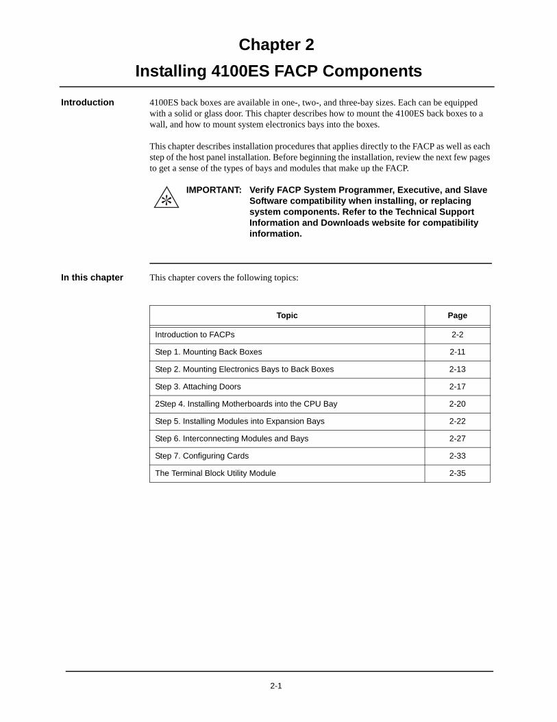
Chapter 2
Installing 4100ES FACP Components
Introduction 4100ES back boxes are available in one-, two-, and three-bay sizes. Each can be equipped with a solid or glass door. This chapter describes how to mount the 4100ES back boxes to a wall, and how to mount system electronics bays into the boxes.
This chapter describes installation procedures that applies directly to the FACP as well as each step of the host panel installation. Before beginning the installation, review the next few pages to get a sense of the types of bays and modules that make up the FACP.
In this chapter This chapter covers the following topics:
IMPORTANT: Verify FACP System Programmer, Executive, and Slave Software compatibility when installing, or replacing system components. Refer to the Technical Support Information and Downloads website for compatibility information.
Topic Page
Introduction to FACPs 2-2
Step 1. Mounting Back Boxes 2-11
Step 2. Mounting Electronics Bays to Back Boxes 2-13
Step 3. Attaching Doors 2-17
2Step 4. Installing Motherboards into the CPU Bay 2-20
Step 5. Installing Modules into Expansion Bays 2-22
Step 6. Interconnecting Modules and Bays 2-27
Step 7. Configuring Cards 2-33
The Terminal Block Utility Module 2-35
2-1
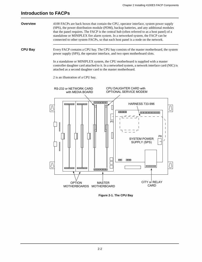
Chapter 2 Installing 4100ES FACP Components
Introduction to FACPs
Overview 4100 FACPs are back boxes that contain the CPU, operator interface, system power supply (SPS), the power distribution module (PDM), backup batteries, and any additional modules that the panel requires. The FACP is the central hub (often referred to as a host panel) of a standalone or MINIPLEX fire alarm system. In a networked system, the FACP can be connected to other system FACPs, so that each host panel is a node on the network.
CPU Bay Every FACP contains a CPU bay. The CPU bay consists of the master motherboard, the system power supply (SPS), the operator interface, and two open motherboard slots.
In a standalone or MINIPLEX system, the CPU motherboard is supplied with a master controller daughter card attached to it. In a networked system, a network interface card (NIC) is attached as a second daughter card to the master motherboard.
2 is an illustration of a CPU bay.
Figure 2-1. The CPU Bay
SYSTEM POWER SUPPLY (SPS)
OPTION MOTHERBOARDS
MASTER MOTHERBOARD
CITY or RELAY CARD
CPU DAUGHTER CARD with OPTIONAL SERVICE MODEM
RS-232 or NETWORK CARD with MEDIA BOARD
HARNESS 733-996
P8
P1
2-2
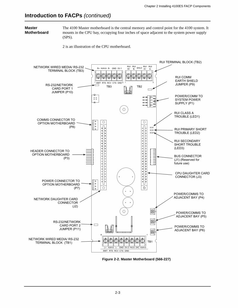
Chapter 2 Installing 4100ES FACP Components
Introduction to FACPs (continued)
Master Motherboard
The 4100 Master motherboard is the central memory and control point for the 4100 system. It mounts in the CPU bay, occupying four inches of space adjacent to the system power supply (SPS).
2 is an illustration of the CPU motherboard.
Figure 2-2. Master Motherboard (566-227)
XMIT1
1
5
8
1 5RTS
TB3 TB2
TB1
RCV CTS GND
L+
XMIT
RSRVD
RTS
L-
RCV
GND
CTS
0V-2
GND
PIEZO 24C RSRVD
R+ RSRVD R- GND 0V-1RUIB+
RUIB- SHLD
RUIA+
RUIA-
RUI TERMINAL BLOCK (TB2) NETWORK WIRED MEDIA/ RS-232
TERMINAL BLOCK (TB3)
POWER/COMM TO SYSTEM POWER SUPPLY (P1)
RUI CLASS A TROUBLE (LED1)
RUI PRIMARY SHORT TROUBLE (LED2)
RUI SECONDARY SHORT TROUBLE (LED3)
BUS CONNECTOR (J1) (Reserved for future use)
POWER/COMMS TO ADJACENT BAY (P4)
POWER/COMMS TO ADJACENT BAY (P5)
POWER/COMMS TO ADJACENT BAY (P6)
NETWORK WIRED MEDIA/ RS-232 TERMINAL BLOCK (TB1)
HEADER CONNECTOR TO OPTION MOTHERBOARD
(P3)
CPU DAUGHTER CARD CONNECTOR (J3)
POWER CONNECTOR TO OPTION MOTHERBOARD
(P7)
COMMS CONNECTOR TO OPTION MOTHERBOARD
(P8)
NETWORK DAUGHTER CARD CONNECTOR
(J2)
RUI COMM EARTH SHIELD JUMPER (P9) RS-232/NETWORK
CARD PORT 1 JUMPER (P10)
RS-232/NETWORK CARD PORT 2 JUMPER (P11)
2-3
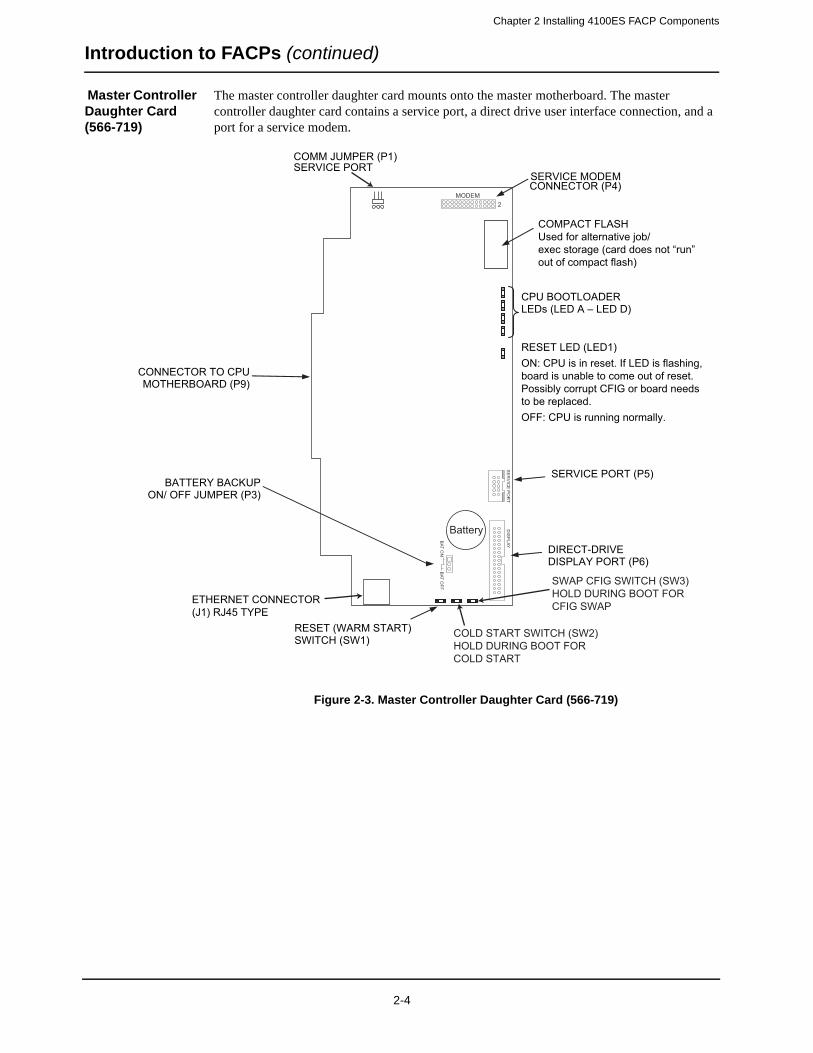
Chapter 2 Installing 4100ES FACP Components
Introduction to FACPs (continued)
Master Controller Daughter Card (566-719)
The master controller daughter card mounts onto the master motherboard. The master controller daughter card contains a service port, a direct drive user interface connection, and a port for a service modem.
Figure 2-3. Master Controller Daughter Card (566-719)
MODEM2
1D
EL2
DEL
3D
E LYA
LP
SID
TR
OP
EC I
VR
ES
FFO
TAB
NO
T AB
SERVICE MODEM CONNECTOR (P4)
BATTERY BACKUP ON/ OFF JUMPER (P3)
SERVICE PORT (P5)
DIRECT-DRIVE DISPLAY PORT (P6)
CONNECTOR TO CPU MOTHERBOARD (P9)
SERVICE PORT COMM JUMPER (P1)
CPU BOOTLOADER LEDs (LED A – LED D)
RESET LED (LED1)ON: CPU is in reset. If LED is flashing,board is unable to come out of reset. Possibly corrupt CFIG or board needs to be replaced.OFF: CPU is running normally.
RESET (WARM START)SWITCH (SW1)
Battery
ETHERNET CONNECTOR(J1) RJ45 TYPE
SWAP CFIG SWITCH (SW3)HOLD DURING BOOT FORCFIG SWAP
COLD START SWITCH (SW2)HOLD DURING BOOT FOR COLD START
COMPACT FLASHUsed for alternative job/exec storage (card does not “run” out of compact flash)
2-4
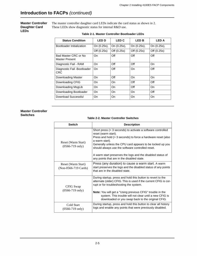
Chapter 2 Installing 4100ES FACP Components
Introduction to FACPs (continued)
Master Controller Daughter Card LEDs
The master controller daughter card LEDs indicate the card status as shown in 2.These LEDs show diagnostic status for internal R&D use.
Master Controller Switches
Table 2-1. Master Controller Bootloader LEDs
Status Condition LED D LED C LED B LED A
Bootloader Initialization On (0.25s), On (0.25s), On (0.25s), On (0.25s),
Off (0.25s) Off (0.25s) Off (0.25s) Off (0.25s)
Bad Master CRC or No Master Present
On Off Off Off
Diagnostic Fail - RAM On Off Off On
Diagnostic Fail -Bootloader CRC
On Off On Off
Downloading Master On Off On On
Downloading CFIG On On Off Off
Downloading MsgLib On On Off On
Downloading Bootloader On On On Off
Download Successful On On On On
Table 2-2. Master Controller Switches
Switch Description
Reset (Warm Start)(0566-719 only)
Short press (< 3 seconds) to activate a software controlled reset (warm start).Press and hold (> 3 seconds) to force a hardware reset (also a warm start).Generally unless the CPU card appears to be locked up you should always use the software controlled reset.
A warm start preserves the logs and the disabled status of any points that are in the disabled state.
Reset (Warm Start)(Non-0566-719 Cards)
Press (any duration) to cause a warm start. A warm start preserves the logs and the disabled status of any points that are in the disabled state.
CFIG Swap(0566-719 only)
During startup, press and hold this button to revert to the alternate (older) CFIG. This is used if the current CFIG is cor-rupt or for troubleshooting the system.
Note: You will get a "Using previous CFIG" trouble in the system. This trouble will not clear until a new CFIG is downloaded or you swap back to the original CFIG.
Cold Start(0566-719 only)
During startup, press and hold this button to clear all history logs and enable any points that were previously disabled.
2-5
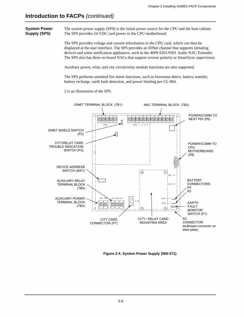
Chapter 2 Installing 4100ES FACP Components
Introduction to FACPs (continued)
System Power Supply (SPS)
The system power supply (SPS) is the initial power source for the CPU and the host cabinet. The SPS provides 24 VDC card power to the CPU motherboard.
The SPS provides voltage and current information to the CPU card, which can then be displayed at the user interface. The SPS provides an IDNet channel that supports initiating devices and some notification appliances, such as the 4009-9201/9301 Audio NAC Extender. The SPS also has three on-board NACs that support reverse polarity or SmartSync supervision.
Auxiliary power, relay, and city circuit/relay module functions are also supported.
The SPS performs standard fire alarm functions, such as brownout detect, battery transfer, battery recharge, earth fault detection, and power limiting per UL 864.
2 is an illustration of the SPS.
Figure 2-4. System Power Supply (566-071)
CITY / RELAY CARD MOUNTING AREA
CITY CARD CONNECTOR (P7)
AUXILIARY RELAY TERMINAL BLOCK
(TB4)
AUXILIARY POWER TERMINAL BLOCK
(TB3)
ACCONNECTOR (bulkhead connector on steel plate)
BATTERY CONNECTORS: P4P5
POWER/COMM TO CPUMOTHERBOARD (P8)
DEVICE ADDRESS SWITCH (SW1)
IDNET SHIELD SWITCH (P2)
CITY/RELAY CARD TROUBLE INDICATION
SWITCH (P3)
EARTHFAULTMONITOR SWITCH (P1)
NAC TERMINAL BLOCK (TB2) IDNET TERMINAL BLOCK (TB1)
POWER/COMM TO NEXT PDI (P6)
2-6
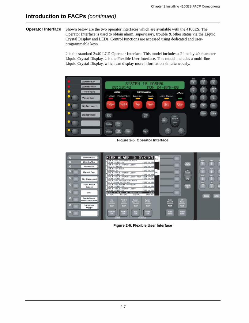
Chapter 2 Installing 4100ES FACP Components
Introduction to FACPs (continued)
Operator Interface Shown below are the two operator interfaces which are available with the 4100ES. The Operator Interface is used to obtain alarm, supervisory, trouble & other status via the Liquid Crystal Display and LEDs. Control functions are accessed using dedicated and user-programmable keys.
2 is the standard 2x40 LCD Operator Interface. This model includes a 2 line by 40 character Liquid Crystal Display. 2 is the Flexible User Interface. This model includes a multi-line Liquid Crystal Display, which can display more information simultaneously.
Figure 2-5. Operator Interface
Figure 2-6. Flexible User Interface
2-7
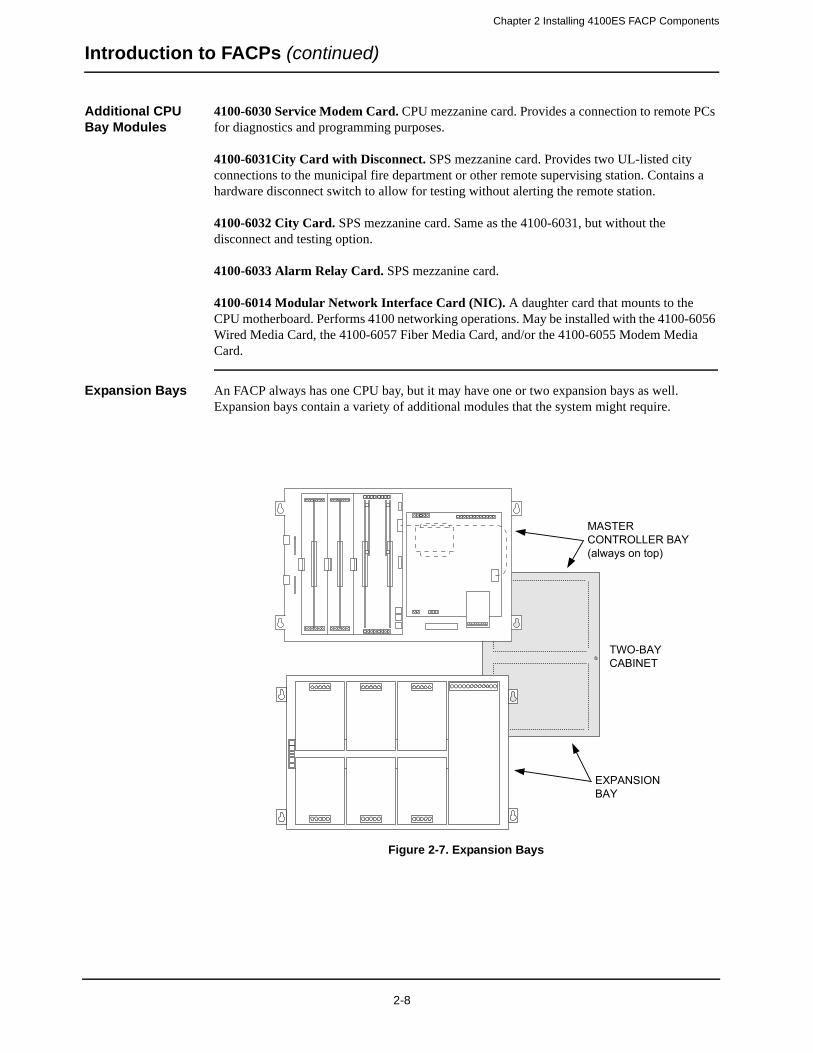
Chapter 2 Installing 4100ES FACP Components
Introduction to FACPs (continued)
Additional CPU Bay Modules
4100-6030 Service Modem Card. CPU mezzanine card. Provides a connection to remote PCs for diagnostics and programming purposes.
4100-6031City Card with Disconnect. SPS mezzanine card. Provides two UL-listed city connections to the municipal fire department or other remote supervising station. Contains a hardware disconnect switch to allow for testing without alerting the remote station.
4100-6032 City Card. SPS mezzanine card. Same as the 4100-6031, but without the disconnect and testing option.
4100-6033 Alarm Relay Card. SPS mezzanine card.
4100-6014 Modular Network Interface Card (NIC). A daughter card that mounts to the CPU motherboard. Performs 4100 networking operations. May be installed with the 4100-6056 Wired Media Card, the 4100-6057 Fiber Media Card, and/or the 4100-6055 Modem Media Card.
Expansion Bays An FACP always has one CPU bay, but it may have one or two expansion bays as well. Expansion bays contain a variety of additional modules that the system might require.
Figure 2-7. Expansion Bays
TWO-BAYCABINET
MASTERCONTROLLER BAY(always on top)
EXPANSIONBAY
2-8

Chapter 2 Installing 4100ES FACP Components
Introduction to FACPs (continued)
System Power The FACP is powered primarily by the SPS, which in turn gets its power from the power distribution module (PDM). The AC branch circuit and the standby battery connect to the PDM. AC and battery power are then distributed to power modules from the PDM via harness.
In expansion bays, the PDM may connect to the following: a secondary system power supply (SPS)*, a remote power supply (RPS), an expansion power supply (XPS), or a 100 W Amplifier.
Note: *The 4100-5111/5112/5113 SPS is available for expansion bays only.
Figure 2-8 System Power
Power Requirements
120V Systems: 4A per SPS, XPS, RPS or 100W Amplifier
220/230/240 V Systems: 2A per SPS, XPS, RPS or 100W Amplifier
SPS
ACBTRY
ACBTRY
ACBTRY
XPS
XPS SPS = System Power Supply XPS = Expansion Power Supply PDM = Power Distribution Module
PDM
INCOMING AC POWER
BATTERY BATTERY
IMPORTANT: AC power must be provided to the 4100ES from a dedicated branch circuit.
2-9

Chapter 2 Installing 4100ES FACP Components
Introduction to FACPs (continued)
The Power Distribution Interface (PDI)
In expansion bays, power and data are distributed via the power distribution interface (PDI). The PDI is a wiring board with eight card slots, each of which can accommodate a 4-inch X 5-inch slave card. If motherboards are used, they must be mounted above the PDI using metal standoffs.
Figure 2-9.The Power Distribution Interface (PDI)
4100 POWER DISTRIBUTION INTERFACEASSY 566-084
POWER/COMMS CONNECTORS
(P1-P3)
AUDIOINTERFACE
CONNECTORS (P6, P7)
POWER SOURCE JUMPERS
(P4, P5)
2-10

Chapter 2 Installing 4100ES FACP Components
Step 1. Mounting Back Boxes
Overview Three different sizes of system back boxes are available, accommodating one, two, or three electronics bays. These back boxes are shipped in large containers separate from the system electronics. If system electronics containers are shipped with the back box containers, store the system electronics containers in a safe, clean, and dry location until the back box installation is completed, and you are ready to install the system electronic bay(s).
Note:
• Conductor entrance and routing restrictions apply to power-limited systems only.
• All back box PIDs are listed in Chapter 1.
Specifications 2 lists the specifications for the back boxes.
Make certain that you have the necessary hardware before you begin the installation procedure. The Back Box Mounting Hardware Kit should have all of the items listed in 2.
Table 2-3. Back Box Specifications
PIDNumber
DescriptionBox Height
Width Rough Opening
Size Weight Door Box Height Width4100-2102/21122975-9408/9411
2 Bays 52 lb.(24 kg)
40 in.(1,016 mm)
24 in.(610 mm)
24 in.(610 mm)
36-3/4 in.(933 mm)
26 1/4 in.(667 mm)
4100-2103/21132975-9409/9412
3 Bays 76 lb.(34 kg)
56 in.(1,422 mm)
24 in.(610 mm)
24 in.(610 mm)
52 5/8 in.(1,337 mm)
26 1/4 in.(667 mm)
Table 2-4. Contents of the Back Box Mounting Hardware Kit
Part Number DescriptionQuantity Per Back Box
1-Bay Box 2-Bay Box 3-Bay Box
268-010 Lockwasher (No. 8) 4 8 12
490-011 Washer 4 8 12
426-033 Screw (No. 8 Torx, 5/16 in.) 4 8 12
2-11

Chapter 2 Installing 4100ES FACP Components
Step 1. Mounting Back Boxes (continued)
Installing the Back Box(es)
Install the back box as shown in 2. Use the holes in the back box to secure it to the wall.
Note:
• For mounting to a wooden wall structure, the back box must be attached with four
• 1-½-inch-long (38 mm) lag bolts and four ½-inch-diameter (13 mm) washers.
• For surface mounting, secure the box to the wall using the tear-drop mounting holes on the back surface. For flush and semi-flush mounting, secure the box to the wall studs using the knockouts on the sides of the box. Note that the front surface of the back box must protrude at least three inches from the wall surface for semi-flush installations.
• Power-limited systems have back box entrance and routing restrictions for field wiring. Do not locate power-limited wiring in the shaded areas of the back box shown in 2. Do not use the upper right, right, or bottom knockouts for entrance of power-limited wiring. Those areas are reserved for non power-limited circuitry such as AC power, batteries, and the city connection.
Figure 2-10. Back Box Installation2 notes:
1. Dimensions shown are typical for all surface and semi-flush installations.
2. Use suitable punch when conduit is required. No knockouts are provided for contractor wiring.
3. Minimum distance between boxes is 3 ¼ inches (83 mm). Maximum distance between boxes
is 6 inches (152 mm).
4. Do not install any power-limited wiring in the shaded area of the back box as shown in 2. This
area is reserved for non power-limited devices and circuits (for example, AC power, batteries,
and city circuits). The non power-limited area is determined by the internal barriers, but is
always below and to the right of these barriers.
TRIM
TOP TOP
RESERVED FOR BATTERIES(SEE NOTE 6)
ADDITIONAL BACK BOX
USE 4 HOLES TOSECURE BACKBOX TO THE WALL
USE 4 HOLES TOSECURE BACKBOX TO THE WALL
1 13/32” (36 mm)
24” (610 mm)
3 17/32” (90 mm)
5 17/32” (140 mm)
16” (406 mm)
See Note 3
6 29/32” (175 mm)
22” (559 mm)
(ONEBAY)
2-12
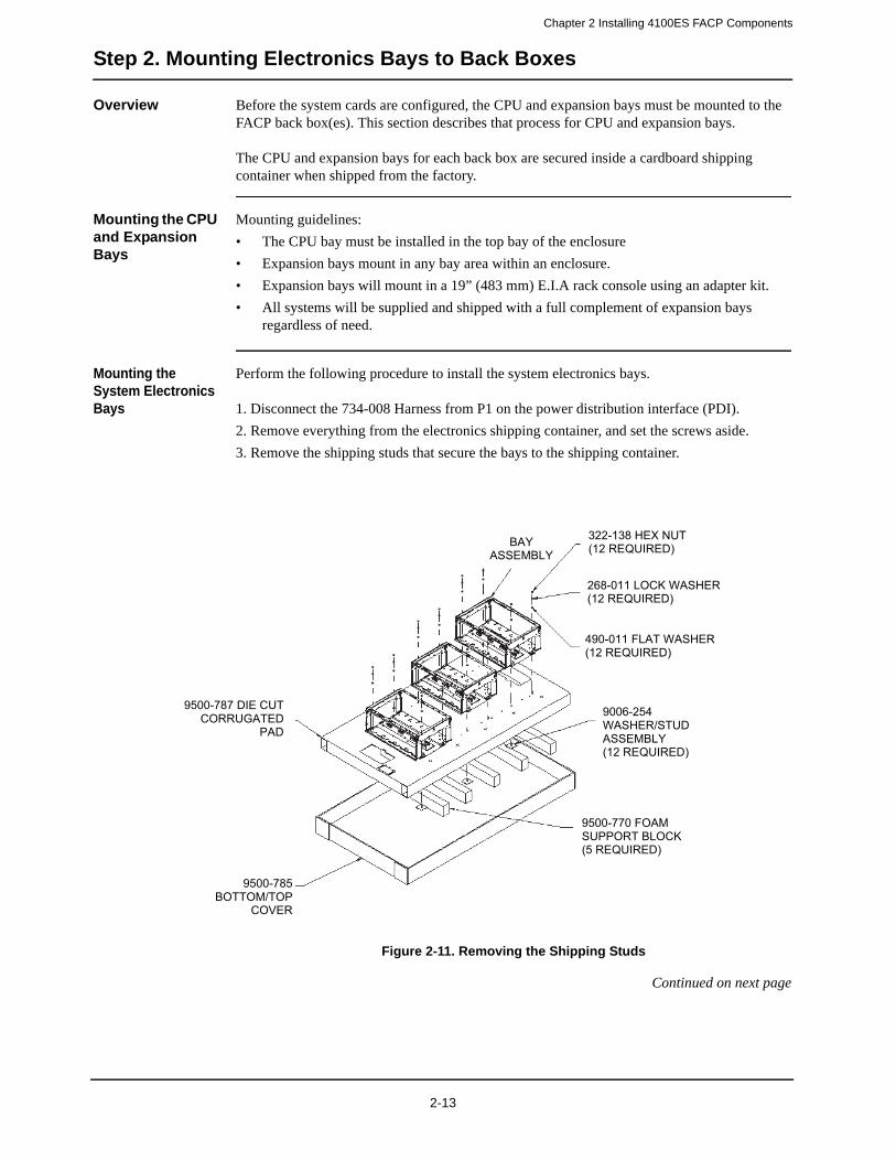
Chapter 2 Installing 4100ES FACP Components
Step 2. Mounting Electronics Bays to Back Boxes
Overview Before the system cards are configured, the CPU and expansion bays must be mounted to the FACP back box(es). This section describes that process for CPU and expansion bays.
The CPU and expansion bays for each back box are secured inside a cardboard shipping container when shipped from the factory.
Mounting the CPU and Expansion Bays
Mounting guidelines:
• The CPU bay must be installed in the top bay of the enclosure
• Expansion bays mount in any bay area within an enclosure.
• Expansion bays will mount in a 19” (483 mm) E.I.A rack console using an adapter kit.
• All systems will be supplied and shipped with a full complement of expansion bays regardless of need.
Mounting the System Electronics Bays
Perform the following procedure to install the system electronics bays.
1. Disconnect the 734-008 Harness from P1 on the power distribution interface (PDI).
2. Remove everything from the electronics shipping container, and set the screws aside.
3. Remove the shipping studs that secure the bays to the shipping container.
Figure 2-11. Removing the Shipping Studs
Continued on next page
322-138 HEX NUT (12 REQUIRED)
268-011 LOCK WASHER (12 REQUIRED)
490-011 FLAT WASHER (12 REQUIRED)
BAY ASSEMBLY
9500-787 DIE CUT CORRUGATED
PAD
9500-785BOTTOM/TOP
COVER
9500-770 FOAM SUPPORT BLOCK (5 REQUIRED)
9006-254WASHER/STUDASSEMBLY (12 REQUIRED)
2-13
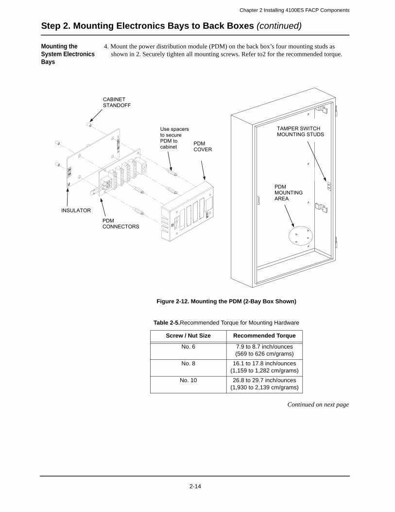
Chapter 2 Installing 4100ES FACP Components
Step 2. Mounting Electronics Bays to Back Boxes (continued)
Mounting the System Electronics Bays
4. Mount the power distribution module (PDM) on the back box’s four mounting studs as shown in 2. Securely tighten all mounting screws. Refer to2 for the recommended torque.
Figure 2-12. Mounting the PDM (2-Bay Box Shown)
Continued on next page
PDMMOUNTING AREA
TAMPER SWITCH MOUNTING STUDS
PDMCOVER
Use spacers to secure PDM to cabinet
PDMCONNECTORS
INSULATOR
CABINETSTANDOFF
Table 2-5.Recommended Torque for Mounting Hardware
Screw / Nut Size Recommended Torque
No. 6 7.9 to 8.7 inch/ounces(569 to 626 cm/grams)
No. 8 16.1 to 17.8 inch/ounces(1,159 to 1,282 cm/grams)
No. 10 26.8 to 29.7 inch/ounces(1,930 to 2,139 cm/grams)
2-14
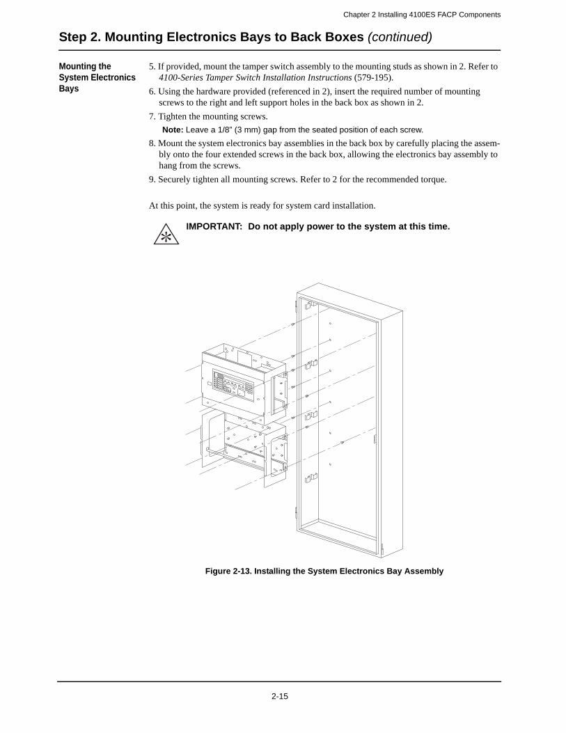
Chapter 2 Installing 4100ES FACP Components
Step 2. Mounting Electronics Bays to Back Boxes (continued)
Mounting the System Electronics Bays
5. If provided, mount the tamper switch assembly to the mounting studs as shown in 2. Refer to 4100-Series Tamper Switch Installation Instructions (579-195).
6. Using the hardware provided (referenced in 2), insert the required number of mounting screws to the right and left support holes in the back box as shown in 2.
7. Tighten the mounting screws.
Note: Leave a 1/8” (3 mm) gap from the seated position of each screw.
8. Mount the system electronics bay assemblies in the back box by carefully placing the assem-bly onto the four extended screws in the back box, allowing the electronics bay assembly to hang from the screws.
9. Securely tighten all mounting screws. Refer to 2 for the recommended torque.
At this point, the system is ready for system card installation.
Figure 2-13. Installing the System Electronics Bay Assembly
IMPORTANT: Do not apply power to the system at this time.
2-15

Chapter 2 Installing 4100ES FACP Components
Step 2. Mounting Electronics Bays to Back Boxes (continued)
Mounting the Trim Bands
The 2975-9811, 2975-9812 and 2975-9813 Semi-Flush Trim Bands may be mounted at any point after the back box has been mounted to the wall. To mount the trim bands:
1. Secure one of the bottom two corner trim bands to the wall using one sheet-rock screw.
2. Slide one of the flat, long trim bands under the side of the corner trim band, and ensure that the flat trim band sticks to the wall.
3. Secure another corner trim band to the other bottom corner, as you did in step 1. This trim band will mount over the side of the flat band.
4. Continue steps 2 and 3 until the back box is surrounded by the trim band.
2-16
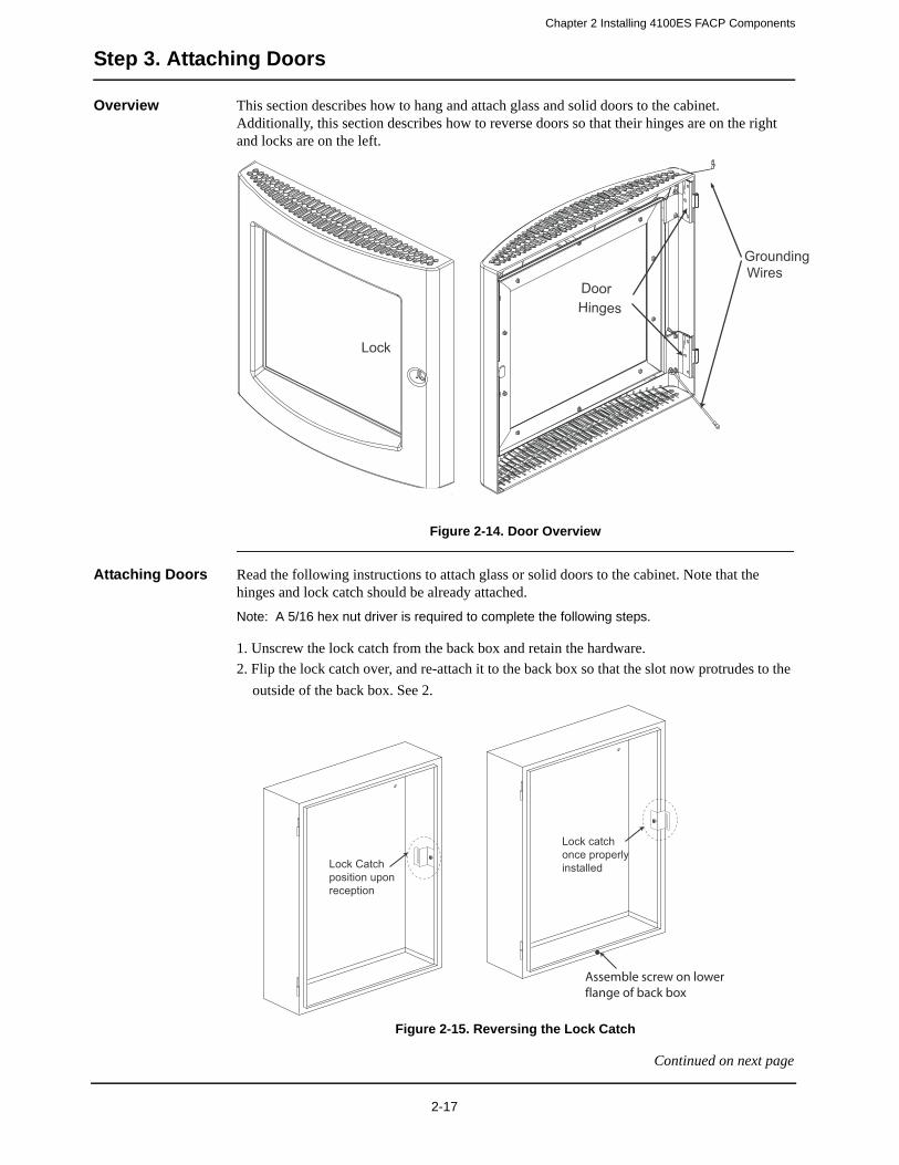
Chapter 2 Installing 4100ES FACP Components
Step 3. Attaching Doors
Overview This section describes how to hang and attach glass and solid doors to the cabinet. Additionally, this section describes how to reverse doors so that their hinges are on the right and locks are on the left.
Figure 2-14. Door Overview
Attaching Doors Read the following instructions to attach glass or solid doors to the cabinet. Note that the hinges and lock catch should be already attached.
Note: A 5/16 hex nut driver is required to complete the following steps.
1. Unscrew the lock catch from the back box and retain the hardware.
2. Flip the lock catch over, and re-attach it to the back box so that the slot now protrudes to the
outside of the back box. See 2.
Figure 2-15. Reversing the Lock Catch
Continued on next page
Front View of a 1 Bay Enclosure Door Back View of a 1 Bay Enclosure Door
DoorHinges
Grounding Wires
Lock
Lock Catchposition uponreception
Lock catchonce properly installed
Assemble screw on lowerflange of back box
2-17

Chapter 2 Installing 4100ES FACP Components
Step 3. Attaching Doors (continued)
Attaching Doors 3. Remove the glass or solid door from the packaging. If a dress panel is used, use the #6 torx screw provided to secure the dress panel onto the back box.
4. Position the dress panel onto the back box and assemble the screw on the lower flange of the back box. See 2.
5. Align the door hinges with the hinge pins on the back box, and slide the door down onto the hinge pins. See 2.
Figure 2-16. Hinge Alignment
Continued on next page
Door Hinge
Cabinet Hinge Pin
2-18

Chapter 2 Installing 4100ES FACP Components
Step 3. Attaching Doors (continued)
Attaching Doors 6. Attach the two ground wire to the back box with the # 6 hex flange nuts in the shipping group (the grounding straps should already be attached to the door). See 2.
Figure 2-17. The Ground Wire
7. Remove the two B-keys that are attached to the door, and keep them in a safe place.
Reversing the Door
Read the following instructions to reverse doors so that their hinges are on the right and locks are on the left. Be sure to retain all hardware.
Note: A 5/16 hex nut driver is required to complete the following steps.
1. Disconnect the ground wires from the back box and set them aside.
2. Remove the door (if it is attached) by lifting it up off the back box’s hinge pins. Set the door aside.
3. Remove the lock catch and its screws from the right side of the back box.
4. Attach the lock catch to the left side of the back box so that the slot protrudes to the outside of the back box.
5. Use a 1/8 (3 mm) punch and hammer to remove the hinge pins from the hinge leaves on the back box.
6. Reinsert the hinge pins so that the length of the pins face toward the bottom of the back box.
7. Remove all of the hinge hardware from the left side of the back box.
8. Attach the hinge hardware to the right side of the back box, so that the hinge pins are facing toward the top of the back box.
9. Turn the door upside down, and then align its hinges to the back box hinge pins. Then slide the door down onto the hinge pins.
10. Re-attach the ground-wire and flange nut to the back box and door.
11. Remove the B-key that is attached to the door, and keep it in a safe place.
Cabinet
Door
Ground Wire
2-19
Chapter 2 Installing 4100ES FACP Components
Step 4. Installing Motherboards into the CPU Bay
Overview This section contains placement guidelines and physical installation instructions on installing traditional motherboards into the 4100ES CPU bay.
This section applies to aftermarket motherboards for the CPU bay only.
• If you do not need to install individual motherboards into the CPU bay, but need to install aftermarket modules into expansion bays, skip to Step 7.
• If you do not need to install any aftermarket modules at all, and if you have followed Steps 1 through 5, you have completed the panel installation and can apply power using the power-up and power-down procedures.
System Power Up Procedure
Power-Up Procedure:
1. Connect only the negative (black) lead of the power supply/charger to the battery.
2. Close and lock the front panel door.
3. Have the appropriate personnel apply AC power to the system from the dedicated circuit breaker or fused disconnect.
4. Ensure the panel has started properly, observing all safety procedures appropriate for a sys-tem with AC power applied.
5. Open the panel door and acknowledge all abnormal conditions including the battery discon-nected trouble condition.
6. Connect the positive (red) lead of the power supply/charger to the battery.
7. Ensure the battery trouble has cleared.
8. Install the panel cover plate (when present), close and lock the door.
System Power Down Procedure
•
Power-Down Procedure:
1. Unlock and open the panel door and remove the cover plate (when present), observing appropriate safety procedures and warnings when the system has AC power present
2. Disconnect only the positive (red) lead of the power supply/charger from the battery
3. Have appropriate personnel remove AC power from the system from the dedicated circuit breaker or fused disconnect
4. Mark or tag the circuit breaker or fused disconnect indicating it is off for service
5. If removing or replacing the battery, disconnect the negative (black) lead and carefully remove the battery.
IMPORTANT: • Never connect or disconnect power on a 4100ES by removing the connector from the PDM. This could cause an improper order of power disconnection which may shorten the product life.
• If this procedure is not followed, you may cause damage to the system and/or create a shock hazard.
WARNING: • Use caution when handling batteries - they can store significant energy and present a shock hazard. When transporting used batteries, be certain the terminals are removed and/or insulated so they cannot make contact with conductive objects and create a safety hazard.
• Use caution when AC power is present. The panel must have power removed while you are performing service on the system.
2-20

Chapter 2 Installing 4100ES FACP Components
Step 4. Installing Motherboards into the CPU Bay (continued)
4100ES CPU Bay Placement Guidelines
Refer to the following guidelines before mounting a motherboard to a CPU bay.
• CPU bays include a CPU with motherboard, a display, and a system power supply (SPS).
• There are eight 2” (51 mm) slots on the CPU bay. Slots 1 and 2 are the only available slots for aftermarket boards.
• CPU bays do not include a power distribution interface (PDI) board, so this bay is reserved for motherboard/daughter card modules only.
• If there are more old style 4100 modules than a CPU bay can accommodate, they should be placed into the next expansion bay.
Figure 2-18. CPU Bay Card Placement
System Power Supply
(SPS)
Chassis
IDNet NACs 1, 2 & 3
AuxPwr
AuxRelays
Btry+-
SPS MezzanineCards
City Circuit4100-60314100-6032
Alarm Relay4100-6033
dBnoitp
O0014
dr aoBrellort noCretsa
M
me doM
e civreS
0306-0014
dBkr o
w teN
sd Ba id e
Mkr o
w teN
dBnoitp
O0014
Slot 1 Slot 2 Slot 3 Slot 4 Slot 5 Slot 6 Slot 7 Slot 8
2-21
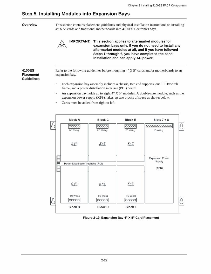
Chapter 2 Installing 4100ES FACP Components
Step 5. Installing Modules into Expansion Bays
Overview This section contains placement guidelines and physical installation instructions on installing 4” X 5” cards and traditional motherboards into 4100ES electronics bays.
4100ES Placement Guidelines
Refer to the following guidelines before mounting 4” X 5” cards and/or motherboards to an expansion bay.
• Each expansion bay assembly includes a chassis, two end supports, one LED/switch frame, and a power distribution interface (PDI) board.
• An expansion bay holds up to eight 4” X 5” modules. A double-size module, such as the expansion power supply (XPS), takes up two blocks of space as shown below.
• Cards must be added from right to left.
Figure 2-19. Expansion Bay 4” X 5” Card Placement
IMPORTANT: This section applies to aftermarket modules for expansion bays only. If you do not need to install any aftermarket modules at all, and if you have followed Steps 1 through 6, you have completed the panel installation and can apply AC power.
2-22

Chapter 2 Installing 4100ES FACP Components
Step 5. Installing Modules into Expansion Bays (continued)
Motherboard Placement Guidelines for a 4100ES bay
• Motherboards can be installed on top of the PDI in expansion bays. The data and power that would normally be bussed via the PDI is instead routed across the boards by a connector from one board to the next.
• Up to eight 2” x 11 ½” motherboards can be installed in an expansion bay if no 4” x 5” modules are installed in the bay, and if the pins on the left connector (usually P1) on the leftmost motherboard are removed. Motherboards are mounted on top of the PDI in expansion bays. The data and power that would normally be bussed via the PDI is instead routed across the boards via ribbon cable from one board to the next.
• Motherboards must be added from left to right.
• Relay motherboards must be the rightmost motherboards.
Figure 2-20. Expansion Bay Motherboard Placement
Power Distribution Interface
dBnoitp
O0014
dBnoitp
O0014
dBnoitp
O0014
dBnoitp
O0014
dBnoitp
O0014
dBnoitp
O0014
dBnoit p
O0014
Slot 2 Slot 3 Slot 4 Slot 5 Slot 6 Slot 7 Slot 8Slot 1
This SlotMust
RemainEmpty
This slot cannot contain a motherboard unless the pins on P1 (or leftmost pin connector) are removed.
Up to eight 2” x 11 ½” motherboards can be mounted in an expansion bay. Seven motherboards fit into Slots 2 through 8; the
eighth can be added in Slot 1 if its leftpost pins are removed.
2-23
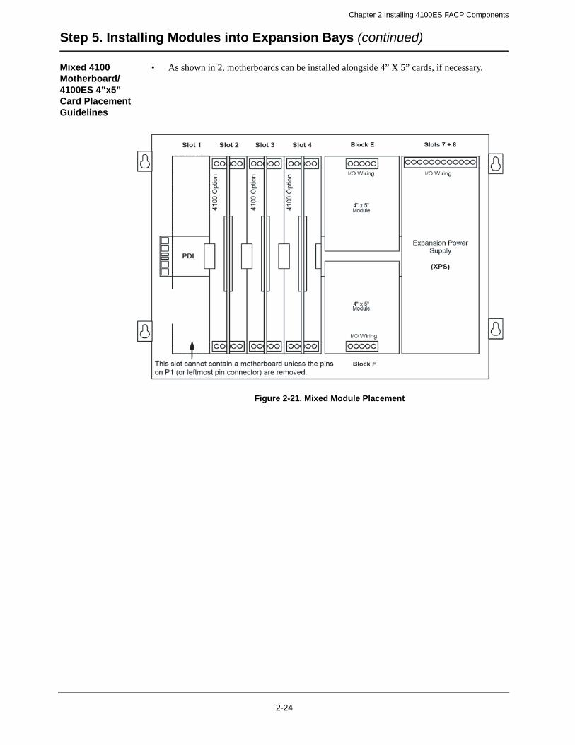
Chapter 2 Installing 4100ES FACP Components
Step 5. Installing Modules into Expansion Bays (continued)
Mixed 4100 Motherboard/4100ES 4”x5” Card Placement Guidelines
• As shown in 2, motherboards can be installed alongside 4” X 5” cards, if necessary.
Figure 2-21. Mixed Module Placement
2-24
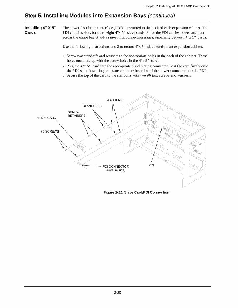
Chapter 2 Installing 4100ES FACP Components
Step 5. Installing Modules into Expansion Bays (continued)
Installing 4” X 5” Cards
The power distribution interface (PDI) is mounted to the back of each expansion cabinet. The PDI contains slots for up to eight 4”x 5” slave cards. Since the PDI carries power and data across the entire bay, it solves most interconnection issues, especially between 4”x 5” cards.
Use the following instructions and 2 to mount 4”x 5” slave cards to an expansion cabinet.
1. Screw two standoffs and washers to the appropriate holes in the back of the cabinet. These holes must line up with the screw holes in the 4”x 5” card.
2. Plug the 4”x 5” card into the appropriate blind mating connector. Seat the card firmly onto the PDI when installing to ensure complete insertion of the power connector into the PDI.
3. Secure the top of the card to the standoffs with two #6 torx screws and washers.
Figure 2-22. Slave Card/PDI Connection
4” X 5” CARD
STANDOFFS
#6 SCREWS
WASHERS
PDI CONNECTOR (reverse side)
PDI
SCREWRETAINERS
2-25

Chapter 2 Installing 4100ES FACP Components
Step 5. Installing Modules into Expansion Bays (continued)
Installing Motherboards into a 4100ES Expansion Bay
Use the following procedure when installing motherboards in an expansion bay. Start with the second slot from the left and fill to the right.1. Orient the motherboard with the connector labeled J1 on the right and the header labeled P1
on the left.
2. Attach four metal threaded standoffs and lockwashers into the screw holes on the chassis.3. Attach two grey plastic standoffs to the motherboard socket mounting screws.4. Secure the motherboard to the standoffs using four #6 torx screws as shown below.
Figure 2-23. Installing the Motherboard in a 4100ES Expansion Bay
#6 SCREWS
LOCKWASHERS
METALSTANDOFFS SCREW HOLES
SCREW HOLES
PLASTIC STANDOFFS
2-26
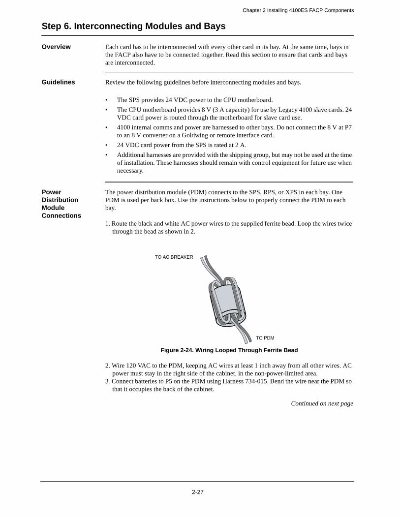
Chapter 2 Installing 4100ES FACP Components
Step 6. Interconnecting Modules and Bays
Overview Each card has to be interconnected with every other card in its bay. At the same time, bays in the FACP also have to be connected together. Read this section to ensure that cards and bays are interconnected.
Guidelines Review the following guidelines before interconnecting modules and bays.
• The SPS provides 24 VDC power to the CPU motherboard.
• The CPU motherboard provides 8 V (3 A capacity) for use by Legacy 4100 slave cards. 24 VDC card power is routed through the motherboard for slave card use.
• 4100 internal comms and power are harnessed to other bays. Do not connect the 8 V at P7 to an 8 V converter on a Goldwing or remote interface card.
• 24 VDC card power from the SPS is rated at 2 A.
• Additional harnesses are provided with the shipping group, but may not be used at the time of installation. These harnesses should remain with control equipment for future use when necessary.
Power Distribution Module Connections
The power distribution module (PDM) connects to the SPS, RPS, or XPS in each bay. One PDM is used per back box. Use the instructions below to properly connect the PDM to each bay.
1. Route the black and white AC power wires to the supplied ferrite bead. Loop the wires twice through the bead as shown in 2.
Figure 2-24. Wiring Looped Through Ferrite Bead
2. Wire 120 VAC to the PDM, keeping AC wires at least 1 inch away from all other wires. AC power must stay in the right side of the cabinet, in the non-power-limited area.
3. Connect batteries to P5 on the PDM using Harness 734-015. Bend the wire near the PDM so that it occupies the back of the cabinet.
Continued on next page
TO AC BREAKER
TO PDM
2-27
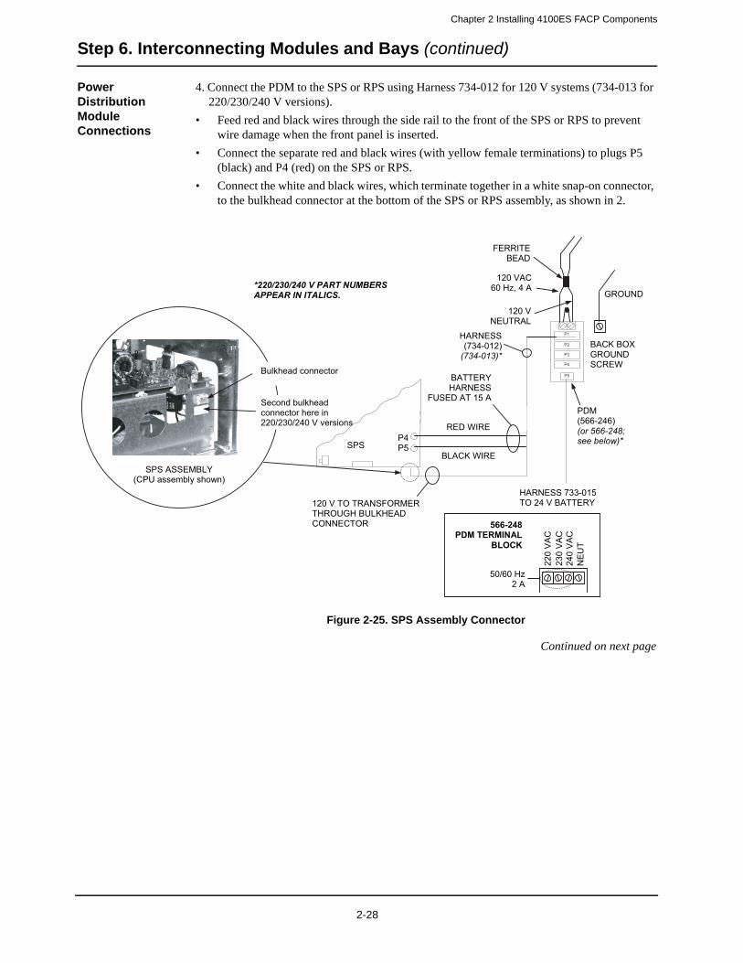
Chapter 2 Installing 4100ES FACP Components
Step 6. Interconnecting Modules and Bays (continued)
Power Distribution Module Connections
4. Connect the PDM to the SPS or RPS using Harness 734-012 for 120 V systems (734-013 for 220/230/240 V versions).
• Feed red and black wires through the side rail to the front of the SPS or RPS to prevent wire damage when the front panel is inserted.
• Connect the separate red and black wires (with yellow female terminations) to plugs P5 (black) and P4 (red) on the SPS or RPS.
• Connect the white and black wires, which terminate together in a white snap-on connector, to the bulkhead connector at the bottom of the SPS or RPS assembly, as shown in 2.
Figure 2-25. SPS Assembly Connector
Continued on next page
P1
P2
P3
P4
P5
SPS
120 V TO TRANSFORMER THROUGH BULKHEAD CONNECTOR
SPS ASSEMBLY (CPU assembly shown)
RED WIRE
BLACK WIRE
P4P5
Bulkhead connector BATTERY HARNESS
FUSED AT 15 A
HARNESS 733-015 TO 24 V BATTERY
HARNESS(734-012)
(734-013)*
GROUND
BACK BOX GROUND SCREW
*220/230/240 V PART NUMBERS APPEAR IN ITALICS.
CA
V022
CA
V032
CA
V042
TU
EN
50/60 Hz 2 A
566-248PDM TERMINAL
BLOCK
Second bulkhead connector here in 220/230/240 V versions
120 V NEUTRAL
120 VAC 60 Hz, 4 A
FERRITEBEAD
PDM(566-246) (or 566-248; see below)*
2-28
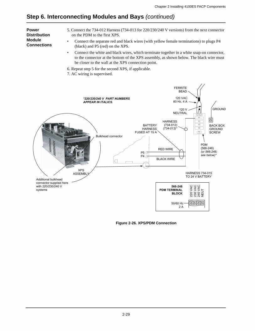
Chapter 2 Installing 4100ES FACP Components
Step 6. Interconnecting Modules and Bays (continued)
Power Distribution Module Connections
5. Connect the 734-012 Harness (734-013 for 220/230/240 V versions) from the next connector on the PDM to the first XPS.
• Connect the separate red and black wires (with yellow female terminations) to plugs P4 (black) and P5 (red) on the XPS.
• Connect the white and black wires, which terminate together in a white snap-on connector, to the connector at the bottom of the XPS assembly, as shown below. The black wire must be closer to the wall at the XPS connection point.
6. Repeat step 5 for the second XPS, if applicable.7. AC wiring is supervised.
Figure 2-26. XPS/PDM Connection
P1
P2
P3
P4
P5
XPSASSEMBLY
Bulkhead connector
HARNESS 734-015 TO 24 V BATTERY
RED WIRE
BLACK WIRE
P5P4
BATTERY HARNESS
FUSED AT 15 A
GROUND
BACK BOX GROUND SCREW
PDM(566-246) (or 566-248; see below)*
HARNESS(734-012)
(734-013)*
CA
V022
CA
V032
CA
V042
TU
EN
50/60 Hz 2 A
566-248PDM TERMINAL
BLOCK
Additional bulkhead connector supplied here with 220/230/240 V systems
120 V NEUTRAL
120 VAC 60 Hz, 4 A
FERRITEBEAD
*220/230/240 V PART NUMBERS APPEAR IN ITALICS.
2-29
Chapter 2 Installing 4100ES FACP Components
Step 6. Interconnecting Modules and Bays (continued)
Card Interconnec-tions in the CPU Bay
Use the following directions to connect the CPU to the SPS and other motherboards (refer to 2).
1. Connect P8 on the SPS to P1 on the CPU motherboard using the eight-position Molex minifit connector (provided).
2. Make sure connector P3 on the CPU is secured to J1 on the next motherboard to the left. Repeat this for the third (leftmost) motherboard, if applicable.
Card Interconnec-tions in Expansion Bays
Expansion bays comprise all bays other than the CPU bay. If you are installing a two- or three-bay FACP, you will be using expansion bays (refer to 2).The power distribution interface (PDI) is mounted to the back of each expansion cabinet. The PDI contains slots for up to eight 4” X 5” slave cards. Since the PDI carries power and data across the entire bay, it solves most interconnection issues, especially between 4” X 5” cards. Refer to “Step 5: Installing Modules into Expansion Bays ” for instructions on mounting 4” X 5” cards to the PDI. Also bear in mind the following variations:
• In a remote expansion cabinet, a transponder interface card (TIC) requires additional interconnections. This occurs in MINIPLEX systems. Refer to Chapter3.
• Regular motherboards require non-PDI interconnections to each other and to the CPU. Refer to “Step 5: Installing Modules into Expansion Bays.”
Basic Bay-To-Bay Interconnections
Panels with two or three bays must be interconnected properly so that they function together as the central point of a standalone or MINIPLEX system, or as a node on a network.
Generally, the CPU bay connects to a local expansion bay using a circuit from CPU to the expansion bay’s PDI. If there is a second expansion bay, the PDI on the first expansion bay connects to the PDI on the second.
Note: Interconnections can become more involved if regular motherboards are used. Refer to “Step 5: Installing Modules into Expansion Bays” if this is the case.
• To connect from the CPU bay to an expansion bay, route the 734-008 Harness from P4, P5, or P6 on the CPU motherboard to P1 on the PDI in the adjacent bay.
• To connect two adjacent expansion bays, route the 734-008 Harness from P2 or P3 on the first PDI to P1 on the PDI in the next bay. Jumpers P4 and P5 are set to positions 2 and 3 (right) to provide card power to the bay from a power supply (SPS, XPS, or RPS) located in the same bay. Jumpers P4 and P5 are set to positions 1 and 2 (left) to provide card power to the bay from P1 on the PDI.
Continued on next page
2-30
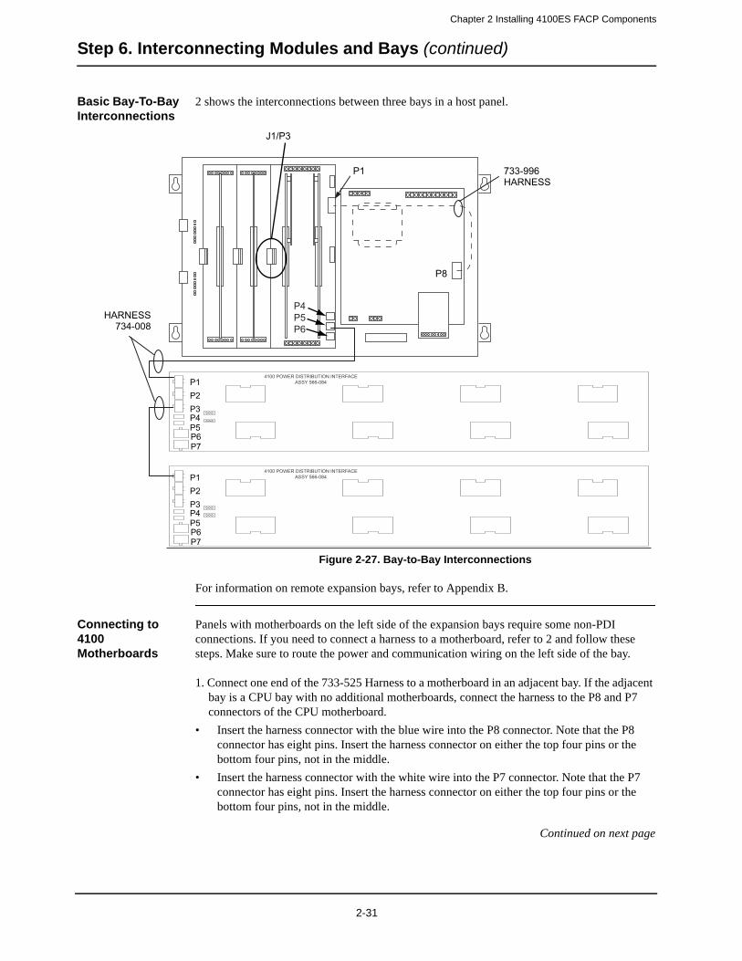
Chapter 2 Installing 4100ES FACP Components
Step 6. Interconnecting Modules and Bays (continued)
Basic Bay-To-Bay Interconnections
2 shows the interconnections between three bays in a host panel.
Figure 2-27. Bay-to-Bay Interconnections
For information on remote expansion bays, refer to Appendix B.
Connecting to 4100 Motherboards
Panels with motherboards on the left side of the expansion bays require some non-PDI connections. If you need to connect a harness to a motherboard, refer to 2 and follow these steps. Make sure to route the power and communication wiring on the left side of the bay.
1. Connect one end of the 733-525 Harness to a motherboard in an adjacent bay. If the adjacent bay is a CPU bay with no additional motherboards, connect the harness to the P8 and P7 connectors of the CPU motherboard.
• Insert the harness connector with the blue wire into the P8 connector. Note that the P8 connector has eight pins. Insert the harness connector on either the top four pins or the bottom four pins, not in the middle.
• Insert the harness connector with the white wire into the P7 connector. Note that the P7 connector has eight pins. Insert the harness connector on either the top four pins or the bottom four pins, not in the middle.
Continued on next page
4100 POWER DISTRIBUTION INTERFACEASSY 566-084
4100 POWER DISTRIBUTION INTERFACEASSY 566-084
HARNESS734-008
P8
733-996HARNESS
P1
P1P2P3P4P5P6P7
P1P2P3P4P5P6P7
J1/P3
P4P5P6
2-31
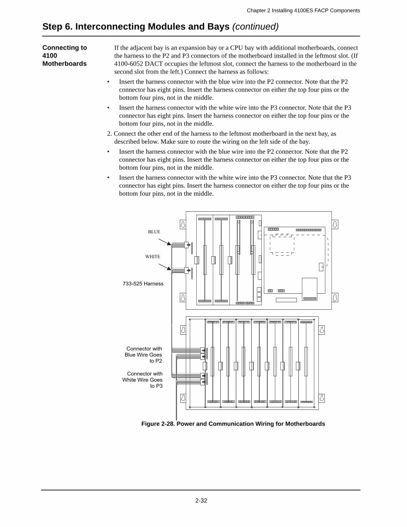
Chapter 2 Installing 4100ES FACP Components
Step 6. Interconnecting Modules and Bays (continued)
Connecting to 4100 Motherboards
If the adjacent bay is an expansion bay or a CPU bay with additional motherboards, connect the harness to the P2 and P3 connectors of the motherboard installed in the leftmost slot. (If 4100-6052 DACT occupies the leftmost slot, connect the harness to the motherboard in the second slot from the left.) Connect the harness as follows:
• Insert the harness connector with the blue wire into the P2 connector. Note that the P2 connector has eight pins. Insert the harness connector on either the top four pins or the bottom four pins, not in the middle.
• Insert the harness connector with the white wire into the P3 connector. Note that the P3 connector has eight pins. Insert the harness connector on either the top four pins or the bottom four pins, not in the middle.
2. Connect the other end of the harness to the leftmost motherboard in the next bay, as described below. Make sure to route the wiring on the left side of the bay.
• Insert the harness connector with the blue wire into the P2 connector. Note that the P2 connector has eight pins. Insert the harness connector on either the top four pins or the bottom four pins, not in the middle.
• Insert the harness connector with the white wire into the P3 connector. Note that the P3 connector has eight pins. Insert the harness connector on either the top four pins or the bottom four pins, not in the middle.
Figure 2-28. Power and Communication Wiring for Motherboards
Connector with Blue Wire Goes
to P2
Connector with White Wire Goes
to P3
733-525 Harness
BLUE
WHITE
2-32
Chapter 2 Installing 4100ES FACP Components
Step 7. Configuring Cards
Overview The CPU, SPS, and all other modules to be mounted in the FACP back box(es) must be configured to operate correctly in the system via their DIP switch and jumper ports. This section describes the hardware configuration for the CPU and SPS, since they will always be used in the CPU bay.
Master Motherboard Configuration
The CPU motherboard must be jumpered as follows (refer to 2):
P9 determines whether the RUI SHIELD signal is connected to 24 C or Earth.
• Position 1 – 2: SHIELD to 24 C (default). Set to this position unless the system uses a TrueAlert Power Supply.
• Position 2 – 3: SHIELD to Earth. Set to this position only if the system uses a TrueAlert Power Supply.
Note: Some devices that connect to RUI have inherently grounded shield terminals, in which case 24 C cannot be used. If 24 C is used, a Negative Ground Fault will occur.
P10/P11: P10 is associated with Port 1 and P11 is associated with Port 2. P10 and P11 are used to set the CPU motherboard up to be attached to either a network card or a RS-232/2120 card.
• Position 1 – 2: Network card (NIC) attached to CPU motherboard (default).
• Position 2 – 3: RS-232/2120 card attached to CPU motherboard.
Master Controller Daughter Card Configuration
The master controller daughter card must be jumpered as follow (refer to 2):
P1 is used for engineering diagnostics (COMLAB).
• Position 1 – 2: Download or no connection.
• Position 2 – 3: Diagnostic mode.
P3 configures the RAM battery as ON or OFF.
• Position 1 – 2: ON.
• Position 2 – 3: OFF.
SPS Configuration
The SPS must be configured as follows (refer to 2):
SW1: Using DIP switch SW1, set the SPS device address. Use the address table in
Appendix A.
P1: Earth connect jumper. Note that the P1 location is clearly designated on the PCB silk screen.
• Position 1 – 2: Enables Earth fault monitoring.
• Position 2 – 3: Disables Earth fault monitoring.
Only one power module should be set for earth fault monitoring for each location within a system. Normally, the SPS in the CPU bay is set to monitor for earth faults. If there is a second SPS connected to the same set of batteries, that SPS should have earth fault monitoring disabled. Other power modules that can be set to monitor earth fault conditions are TPS, RPS and XBC. When located under common 0V with a TPS, the TPS should be set to monitor earth faults, and other co-located power modules should be set to disable earth fault monitoring.
P2: If the SPS IDNet outputs are being used, you may change P2 to configure the IDNet shield connection. Note that the P2 pin 1 location is towards P3.
• Position 1 – 2: Connects the shield to 0 V (default).
• Position 2 – 3: Connects the shield to earth ground.
Continued on next page
2-33
Chapter 2 Installing 4100ES FACP Components
Step 7. Configuring Cards (continued)
SPS Configuration P3: City Card and Relay Card operation. Note that the P3 pin 1 location is towards P2.
• Position 1-2: Install in pos. 1-2 only if a relay card 4100-6033 is installed and has relay 3 programmed for operation other than "Trouble"
• Position 2-3: (default) For City Card operation and for use with 4100-6033 if relay 3 is programmed for "activate on trouble" operation
Note: Refer to Chapter 5 for additional SPS configuration information.Refer to chapter 8 for SPS wiring information.
PDI Configuration P4/P5: The PDI can be configured to draw its power from different sources via P4 and P5 (refer to 2).
• To draw power from an XPS on the PDI, set jumpers on P4 and P5 to position 2 – 3.
• To draw power from P1 (from the SPS or RPS), set jumpers on P4 and P5 to position 1 – 2 (default).
• To remove power from the PDI, remove the jumper from P4.
Configuring Other Cards
Refer to the appropriate installation instructions to configure other cards that are located in CPU and expansion bays. Refer to Appendix E for a list of publications.
2-34

The Terminal Block Utility Module
Overview The 4100-0632 Terminal Block Utility Module is an all-purpose terminal block that mounts to an electronics bay, above or below the power distribution interface (PDI). Each module utilizes one block of mounting space.
The terminal block utility module has two 16-position terminal blocks that accept up to a maximum of 12 AWG (3.309 mm2) wire.
Mounting to the Electronics Bay
Follow the directions below to mount the terminal block utility module to the electronics bay.
1. Align the terminal block utility module to any two compatible screw holes on the electronics bay. Position the higher terminal block towards the middle of the bay. There are eight possi-ble locations: four above and four below the PDI. Refer to 2.
2. Secure the terminal block utility module to the electronics bay with two #6 screws and lock-washers.
3. The shorting strip may be removed or modified, depending on the application.
Figure 2-29. Terminal Block Utility Module Mounting

Chapter 3
Installing 4100ES MINIPLEX Components
Introduction MINIPLEX transponder interface cards (TICs) allow for data and power interconnections between the 4100 host panel and remote locations. This chapter describes the transponder installation procedure for 4100ES MINIPLEX systems.
In this chapter This chapter covers the following topics:
Topic Page
Introduction to MINIPLEX Transponders 3-2
MINIPLEX System Guidelines 3-7
Configuring Cards 3-8
TIC/Riser Mounting 3-9
TIC/Motherboard Interconnections 3-10
RUI Wiring 3-11
MINIPLEX Audio Wiring 3-12
3-1

Chapter 3 Installing 4100ES MINIPLEX Components
Introduction to MINIPLEX Transponders
Overview The 4100ES MINIPLEX system is comprised of a host panel containing everything required in a standalone cabinet (see Chapter 3), plus:
• One or more remote MINIPLEX transponder cabinets
• A transponder interface card (TIC) in each transponder cabinet
This section describes each component in turn.
Transponder Cabinets
RUI Communication wiring from the RUI module in the host panel extends to a transponder interface card (TIC) in a remote transponder cabinet. The transponder cabinet is simply a 2975-94xx Back Box with at least one TIC module in it, and can have one, two, or three bays.
Transponder Interface Cards (TICs) and Audio Riser Modules
The following TICs, audio risers, and audio riser controller modules are available for 4100ES MINIPLEX ® systems:
• Basic Transponder Interface Card (TIC) Module
• Local Mode TIC Module
• Analog Audio Riser Module
• Digital Audio Riser Module
• Network Audio Riser Controller Module
Transponder Interface Cards (TICs) receive data from 4100ES host panels allowing remote locations to perform fire alarm functions. TIC modules are optionally available with local mode operation that provides basic (degraded mode) system functions in the event of a communication loss with the master panel. TICs receive communications from the 4100ES host panel using Remote Interface (RUI) communications with either Style 4 or Style 7 wiring.
For audio systems, audio riser modules are required and are connected directly to TIC modules via ribbon cable. Audio riser modules support Class A and Class B analog wiring, as well as Style 4 and Style 7 digital audio wiring.
Basic TICs The basic TIC is an addressable device that contains an RUI input, audio riser module interface, and a port for connecting to other transponder modules.The basic TICs use the same board, with some variations:
• The basic TIC is an addressable device that contains RUI outputs, an audio riser output, a user interface output, and a port for connecting to motherboards.
• The only connectors on the addressable network audio interface module are the audio riser output and a user interface output.
3-2

Chapter 3 Installing 4100ES MINIPLEX Components
Introduction to MINIPLEX Transponders (continued)
The Local Mode TIC
The local mode TIC contains an RUI input, audio riser module interface, port for connecting to other transponder modules, and terminal block for connecting to an optional Local Mode Controller. Local Mode Controllers are mounted remotely from the transponder and are available in red or beige (flush or surface mount). Model numbers are 4601-9108, -9109, -9110, & -9111. Installation instructions are supplied with the controller.
Local mode operation allows a TIC to provide life safety operations in the event of a communication loss with the master controller. More specifically, this provision means that fire alarm inputs and outputs within the transponder cabinet can still work in a limited capacity to allow continued functioning of local initiating devices and notification appliances connected to the TIC. Local mode is considered a “degraded” mode of operation because full fire alarm system functionality is not guaranteed.
Because the TIC is a slave module that occupies an RUI address, it can indicate a trouble condition to the master controller in the event of a hardware failure. When local mode is initiated, all slave devices locally connected to the TIC are notified by the TIC that local mode is taking effect. From that point until communication is restored to the master controller, the TIC “group-polls” all connected local slaves, and the slaves respond only in the event of an alarm input activation. Other status changes, including troubles, are not reported.
TIC Audio Risers Audio risers are used when digital or analog audio is being transmitted to the transponder cabinet. They are always mounted directly beneath the TIC, on the leftmost side of the transponder bay.
Refer to publication 574-844 to obtain configuration information for 4100-0621, -0622, and -1341 Audio
riser modules.
3-3
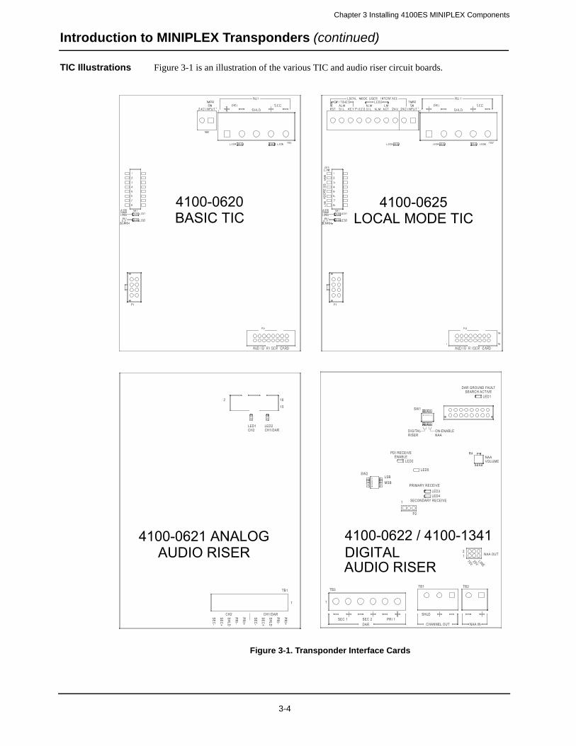
Chapter 3 Installing 4100ES MINIPLEX Components
Introduction to MINIPLEX Transponders (continued)
TIC Illustrations Figure 3-1 is an illustration of the various TIC and audio riser circuit boards.
Figure 3-1. Transponder Interface Cards
TB1
CH2
-CES
+CES
D LHS
-IRP
+IRP
CH1/DAR
-CES
+CES
DLHS
- IRP
+IRP
16
15
2
LED1CH2
LED2CH1/DAR
1
SEC 1
TB3TB2
1
P2
1
TB1
21
SEC 2DAR CHANNEL OUT NAA IN
NAA OUT
NAAVOLUME
R4
SW1
LED1
LED2
LED3LED4
DAR GROUND FAULTSEARCH ACTIVE
PDI RECEIVEENABLE
PRIMARY RECEIVE
SECONDARY RECEIVE
DIGITALRISER
ON-ENABLENAA
1234
SW2LSBMSB
1234
ENILV52
V07
SHLDPRI 1
LED5
4100-0620BASIC TIC
4100-0625LOCAL MODE TIC
4100-0621 ANALOG AUDIO RISER
4100-0622 / 4100-1341 DIGITAL AUDIO RISER
3-4

Chapter 3 Installing 4100ES MINIPLEX Components
Introduction to MINIPLEX Transponders (continued)
Local Mode Specifications
Local mode is supported by the following:
• 4100-3101/3104/3105 IDNet Card
• 4100-5101/5102/5103 Expansion Power Supply NACs (including TrueAlert Non-Addressable SmartSync appliances)
• 4100-5111/5112/5113 System Power Supply NACs (including TrueAlert Non-Addressable SmartSync appliances)
• 4100-5125/5126/5127 Remote Power Supply NACs (including TrueAlert Non-Addressable SmartSync appliances)
• 4100-5120/5121/5122 TrueAlert Power Supply NACs
• 4100-1214 to -1225, 4100-1228 to –1239, 4100-1314 to -1325, 4100-1328 to –1339,
• 100 W Amplifier NACs
• 4100-1212/1213/1226/1227/1312/1313/1326/1327 Flex 50 Amplifier NACs
• 4009-9401 TrueAlert Addressable Controller
• 4100-1270 Phone Controller and 4100-1272/1273 Phone NAC cards
• 4009-9201/ 9301 IDNet NAC Extender
• 4100-5116 Expansion Signal Card
Local mode is NOT supported by, but can co-exist with, the following:
• 4100 Legacy cards
• 4100-3101 to -3103 Auxiliary Relay Cards
• 4100-6048 VESDA™ Interface Kit
• 4100-6043/6044 RS-232/2120 Interfaces
• 4100-1280 to -1287 LED/Switch Annunciators
• 4100-1290 24-Point Graphic I/O Module
• 4602-9101 SCU/ 4602-9102 RCU
• 4603-9101 LCD Annunciator
• 4100-1210/1211/1311 Audio Controller Board
• 4100-6014 Network Interface Card
• 4100-6052 DACT
Bear in mind the following limitations for when local mode is in effect:
• If an alarm is already activated when local mode is initiated, the alarm remains activated in local mode.
• Software zones are not supported. Basic TrueAlert channels are supported.
• Alarm verification is not supported. All alarms are reported immediately.
• SMPL is not supported.
• TrueAlarm sensors have fixed thresholds.
3-5
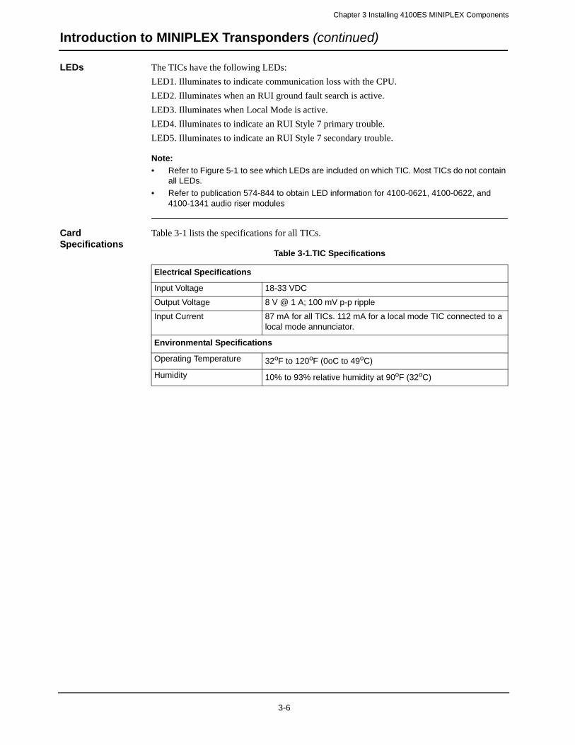
Chapter 3 Installing 4100ES MINIPLEX Components
Introduction to MINIPLEX Transponders (continued)
LEDs The TICs have the following LEDs:
LED1. Illuminates to indicate communication loss with the CPU.
LED2. Illuminates when an RUI ground fault search is active.
LED3. Illuminates when Local Mode is active.
LED4. Illuminates to indicate an RUI Style 7 primary trouble.
LED5. Illuminates to indicate an RUI Style 7 secondary trouble.
Note:
• Refer to Figure 5-1 to see which LEDs are included on which TIC. Most TICs do not contain all LEDs.
• Refer to publication 574-844 to obtain LED information for 4100-0621, 4100-0622, and 4100-1341 audio riser modules
Card Specifications
Table 3-1 lists the specifications for all TICs.
Table 3-1.TIC Specifications
Electrical Specifications
Input Voltage 18-33 VDC
Output Voltage 8 V @ 1 A; 100 mV p-p ripple
Input Current 87 mA for all TICs. 112 mA for a local mode TIC connected to a local mode annunciator.
Environmental Specifications
Operating Temperature 32oF to 120oF (0oC to 49oC)
Humidity 10% to 93% relative humidity at 90oF (32oC)
3-6

Chapter 3 Installing 4100ES MINIPLEX Components
MINIPLEX System Guidelines
Overview The rules on this page apply exclusively to MINIPLEX systems. Review each guideline before installing a MINIPLEX 4100ES system.
Guidelines • All wiring is 18 AWG (0.8231 mm2) (minimum) and 12 AWG (3.309 mm2) (maximum).
• All wiring is supervised and power-limited.
• All wiring that leaves the building requires overvoltage protection. Install module inside an UL-Listed electrical box wherever wire enters or exits the building. A maximum of four 2081-9044 Modules may be connected to one channel. The 2081-9044 is rated for 200 mA (maximum).
• For Style 4 operation:
- The maximum distance to any device is 2,500 feet (762 m).
- “T” taps are allowed.
- The total maximum cable load (including all “T” taps) is 10,000 feet (3,048 m).
- Maximum allowed line-to-line capacitance (“+” to “-” terminals) is 0.58 uF. For appli-cations with shielded wire, be sure that the total capacitance from line to line plus the shield to either line is no more than 0.58 uF.
• For Style 6 or Style 7 operation, the maximum loop distance is 2,500 feet (762 m). “T” taps are not allowed.
• RUI comms are wired to remote cabinets from the CPU motherboard to one of the following transponder interface cards: 4100-0620 (566-093) or 4100-0625 (566-094).
• Annunciators and transponder interface cards support Style 7 operation when the system is wired Class A.
• The master control panel must be a 4100ES Fire Alarm Control Panel.
• The Style 4 RUI card supports MINIPLEX transponders and 4602/4603 serial annuncia-tors on the same signaling line circuit.
• Up to 4 RUI cards in the 4100ES Control Panel can be used for distributing transponder wiring in different directions or for supporting different wiring requirements (such as using a Style 7 RUI for serial annunciators).
• Up to 31 transponders can be controlled from the 4100ES Control Panel, and can be distributed as required among the RUI cards.
3-7

Chapter 3 Installing 4100ES MINIPLEX Components
Configuring Cards
Overview The TIC and all other cards to be mounted in the transponder cabinet and attached expansion bays must be configured to operate correctly in the system via their DIP switch and jumper ports. The CPU motherboard may have to be configured as well.
CPU Motherboard DIP Switch
P9 on the CPU motherboard determines whether the RUI SHIELD signal is connected to 24 C or Earth.
• Position 1 – 2: SHIELD to 24 VDC (default).
• Position 2 – 3: SHIELD to Earth.
Note: Some devices that connect to RUI have inherently grounded shield terminals, in which case 24 C cannot be used. If 24 C is used, a Negative Ground Fault will occur.
TIC Configuration The TIC must be assigned a device address via DIP switch SW1. Refer to Appendix A for the address switch table.
Configuring Other Cards
Refer to the appropriate publication to configure other cards that are located in the transponder cabinet and attached expansion bays.
3-8
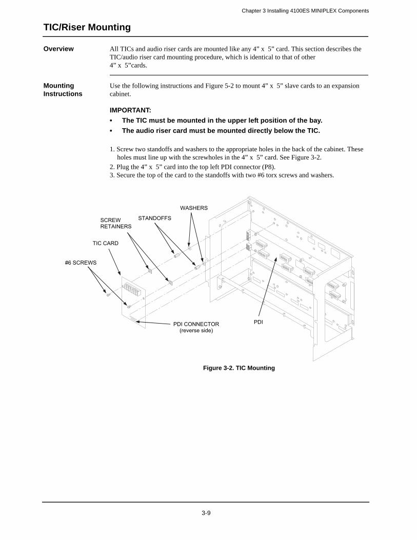
Chapter 3 Installing 4100ES MINIPLEX Components
TIC/Riser Mounting
Overview All TICs and audio riser cards are mounted like any 4” x 5” card. This section describes the TIC/audio riser card mounting procedure, which is identical to that of other 4” x 5”cards.
Mounting Instructions
Use the following instructions and Figure 5-2 to mount 4” x 5” slave cards to an expansion cabinet.
IMPORTANT:
• The TIC must be mounted in the upper left position of the bay.
• The audio riser card must be mounted directly below the TIC.
1. Screw two standoffs and washers to the appropriate holes in the back of the cabinet. These holes must line up with the screwholes in the 4” x 5” card. See Figure 3-2.
2. Plug the 4” x 5” card into the top left PDI connector (P8).3. Secure the top of the card to the standoffs with two #6 torx screws and washers.
Figure 3-2. TIC Mounting
TIC CARD
STANDOFFS
#6 SCREWS
WASHERS
PDI CONNECTOR (reverse side)
PDI
SCREWRETAINERS
3-9
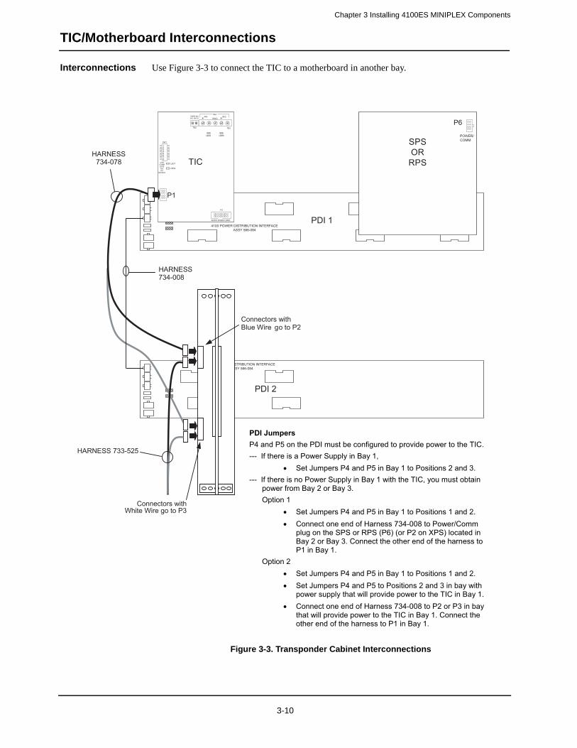
Chapter 3 Installing 4100ES MINIPLEX Components
TIC/Motherboard Interconnections
Interconnections Use Figure 3-3 to connect the TIC to a motherboard in another bay.
Figure 3-3. Transponder Cabinet Interconnections
4100 POWER DISTRIBUTION INTERFACEASSY 566-084
4100 POWER DISTRIBUTION INTERFACEASSY 566-084
LED4
SW1
LED1
TB2
PRI
LED2
P1
P3
LED5
TB3
SECRUI
TMPR SW24C INPUT SHLD
4100COMMLOSSRUIG.F.
SEARCH
AUDIO RISER CARD
HARNESS734-008
TI
SPSOR
RPSC
PDI 1
PDI 2
HARNESS734-078
P1
P6
POWER/COMM
Connectors withWhite Wire go to P3
HARNESS 733-525
Connectors withBlue Wire go to P2
PDI Jumpers P4 and P5 on the PDI must be configured to provide power to the TIC. --- If there is a Power Supply in Bay 1,
• Set Jumpers P4 and P5 in Bay 1 to Positions 2 and 3. --- If there is no Power Supply in Bay 1 with the TIC, you must obtain
power from Bay 2 or Bay 3. Option 1
• Set Jumpers P4 and P5 in Bay 1 to Positions 1 and 2. • Connect one end of Harness 734-008 to Power/Comm
plug on the SPS or RPS (P6) (or P2 on XPS) located in Bay 2 or Bay 3. Connect the other end of the harness to P1 in Bay 1.
Option 2 • Set Jumpers P4 and P5 in Bay 1 to Positions 1 and 2. • Set Jumpers P4 and P5 to Positions 2 and 3 in bay with
power supply that will provide power to the TIC in Bay 1. • Connect one end of Harness 734-008 to P2 or P3 in bay
that will provide power to the TIC in Bay 1. Connect the other end of the harness to P1 in Bay 1.
3-10
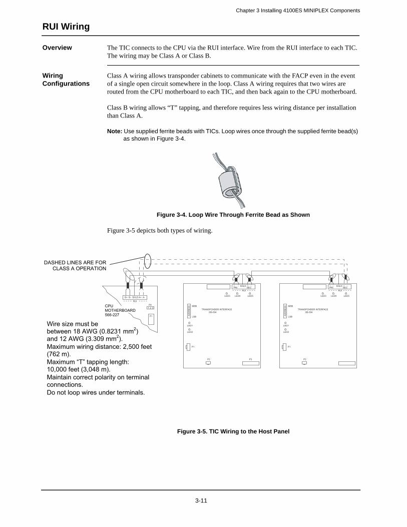
Chapter 3 Installing 4100ES MINIPLEX Components
RUI Wiring
Overview The TIC connects to the CPU via the RUI interface. Wire from the RUI interface to each TIC. The wiring may be Class A or Class B.
Wiring Configurations
Class A wiring allows transponder cabinets to communicate with the FACP even in the event of a single open circuit somewhere in the loop. Class A wiring requires that two wires are routed from the CPU motherboard to each TIC, and then back again to the CPU motherboard.
Class B wiring allows “T” tapping, and therefore requires less wiring distance per installation than Class A.
Note: Use supplied ferrite beads with TICs. Loop wires once through the supplied ferrite bead(s) as shown in Figure 3-4.
Figure 3-4. Loop Wire Through Ferrite Bead as Shown
Figure 3-5 depicts both types of wiring.
Figure 3-5. TIC Wiring to the Host Panel
TRANSPONDER INTERFACEASSY 566-094
MSB
LSB
LED1
SSER
DDA
LED3
PRI
B+ B- SHLD A+ A-
SECRUI
SHLD
LED4 LED5
LED2
P1
P2 P3
RUIP9
P1
1 2 3TRANSPONDER INTERFACEASSY 566-094
MSB
LSB
LED1
SSER
DDA
LED3
PRI SECRUI
SHLD
LED4 LED5
LED2
P1
P2
DASHED LINES ARE FOR CLASS A OPERATION
Wire size must be between 18 AWG (0.8231 mm2)and 12 AWG (3.309 mm2).Maximum wiring distance: 2,500 feet (762 m). Maximum “T” tapping length: 10,000 feet (3,048 m). Maintain correct polarity on terminal connections. Do not loop wires under terminals.
CPUMOTHERBOARD 566-227
3-11
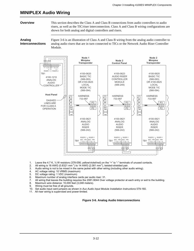
Chapter 3 Installing 4100ES MINIPLEX Components
MINIPLEX Audio Wiring
Overview This section describes the Class A and Class B connections from audio controllers to audio risers, as well as the TIC/riser interconnection. Class A and Class B wiring configurations are shown for both analog and digital controllers and risers.
Analog Interconnections
Figure 3-6 is an illustration of Class A and Class B wiring from the analog audio controller to analog audio risers that are in turn connected to TICs or the Network Audio Riser Controller Module.
Figure 3-6. Analog Audio Interconnections
DASHEDLINES ARE
FOR CLASS AOPERATION
4100-0620BASIC TIC(566-093)
OR 4100-0625LOCAL
MODE TIC(566-094)
4100-0620BASIC TIC(566-093)
OR 4100-0625LOCAL
MODE TIC(566-094)
4100-0621ANALOGAUDIORISER
(566-242)
4100-1210ANALOGAUDIO
CONTROLLER(566-218)
TB1RISER 1
1 10
RISER 2
S A A S A A
HARNESS733-997
P3
P2
Node 1Miniplex
Transponder
Node 1Host Panel
Node 2Control Panel
Node 2Miniplex
Transponder
4100-0623AUDIO RISERCONTROLLER
MODULE(566-249)
4100-0621ANALOGAUDIORISER
(566-242)
HARNESS733-997
P3
P2
4100-0621ANALOGAUDIORISER
(566-242)
HARNESS733-997
P3
P2
TB1RISER 1
1 10
RISER 2
SSEC PRI SEC PRI
S TB1RISER 1
1 10
RISER 2
SSEC PRI SEC PRI
S TB1RISER 1
1 10
RISER 2
SSEC PRI SEC PRI
S
1. Leave the 4.7 K, ½ W resistors (378-056; yellow/violet/red) on the “+” to “-” terminals of unused contacts. 2. All wiring is 18 AWG (0.8321 mm 2 ) to 14 AWG (2.081 mm 2), twisted-shielded pair. 3. Audio wiring is not to be mixed in the same jacket with other wiring (including other audio wiring).4. AC voltage rating: 10 VRMS (maximum) 5. DC voltage rating: 1 VDC (maximum) 6. Maximum number of analog interface cards per audio riser: 31. 7. All wiring that leaves the building requires the 2081-9044 Over voltage protector at each entry or exit to the building.8. Maximum wire distance: 10,000 feet (3,048 meters). 9. Wiring must be free of all grounds. 10. Set audio input card jumpers as shown in Aux Audio Input Module Installation Instructions 579-160.11. All riser wiring is supervised and power-limited.
3-12

Chapter 3 Installing 4100ES MINIPLEX Components
MINIPLEX Audio Wiring (continued)
Digital Intercon-nections (4100-1311 Digital Audio Controller)
Figure 3-7 is an illustration of Style 7 and Style 4 (Class B) digital wiring from the digital audio controller to risers connected to TICs or the Network Audio Riser Controller Module.
Figure 3-7. Digital Interconnections (4100-1311 Digital Audio Controller)
NODE N(STYLE 4
ONLY)
NODE P(STYLE 4
ONLY)
DASHEDLINES ARE
FOR STYLE 7OPERATION
(required on primaryand secondary DAR)
Loop wires oncethrough the supplied
ferrite beads as shown
DAR TOPRIMARY
INPUT
DAR TOPRIMARY
INPUT
4100-0622DIGITALAUDIORISER
(566-407)
4100-1311DIGITALAUDIO
CONTROLLER(566-409)
TB3
TB2
TB3 TB3
HARNESS733-997
P3
P2Ferrite Bead
NODE Q(STYLE 4
ONLY)
NODE R(STYLE 4
ONLY)
4100-0622DIGITALAUDIORISER
(566-407)
HARNESS733-997
P3
P2
4100-0622DIGITALAUDIORISER
(566-407)
HARNESS733-997
P3
P2
DAR TOPRIMARY
INPUTNode 1
MiniplexTransponder
Node 1Host Panel
Node 2Control Panel
Node 2Miniplex
Transponder
4100-0620BASIC TIC(566-093)
OR 4100-0625LOCAL
MODE TIC(566-094)
4100-0620BASIC TIC(566-093)
OR 4100-0625LOCAL
MODE TIC(566-094)
4100-0623AUDIO RISERCONTROLLER
MODULE(566-249)
1. All wiring is 24 AWG (0.2047 mm2) to 18 AWG (0.8321 mm2), twisted-pair. 2. Maximum wire distance: 2,500 feet (762 meters) from digital audio controller primary to the digital audio riser card. 3. Maximum distance between subsequent nodes: 2,500 feet (762 meters) 4. Maximum line distance and capacitance between nodes:
18 AWG (0.8321 mm2): 40 Ohms maximum 0.055 μF maximum 24 AWG (0.2047 mm2): 135 Ohms maximum 0.055 μF maximum
5. All wiring that leaves the building requires the 2081-9044 Overvoltage Protector at each entry or exit to the building. A maximum of four overvoltage protectors are allowed. Each 2081-9044 adds 6 Ohms and 0.006 μF.
6. Wiring must be free of all grounds. 7. Maximum number of digital interface cards per digital audio riser: 31. 8. All riser wiring is supervised and power-limited. 9. Audio wiring is not to be mixed in the same jacket with other wiring (including other audio wiring). 10. In applications where no Digital Audio Controller is connected to the field wiring (such as a synchronized audio application or
a non-synchronized application with multiple network microphone s), all DAR interface cards are wired secondary to primary.
3-13

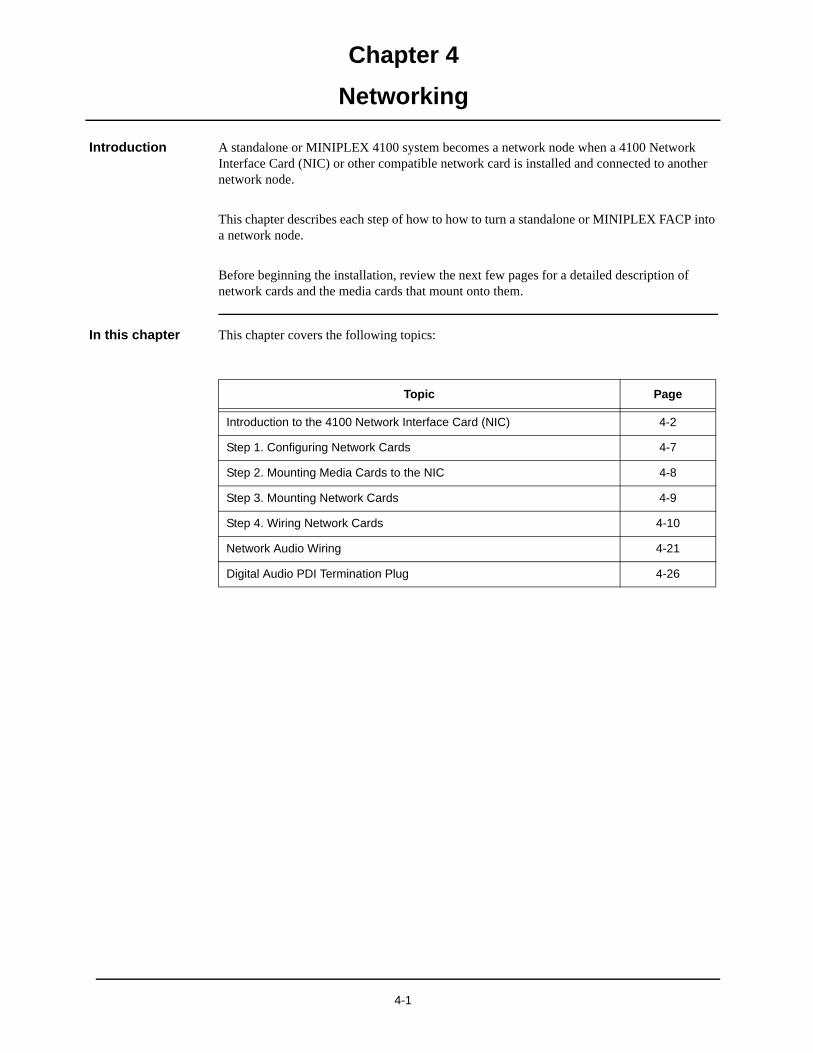
Chapter 4
Networking
Introduction A standalone or MINIPLEX 4100 system becomes a network node when a 4100 Network Interface Card (NIC) or other compatible network card is installed and connected to another network node.
This chapter describes each step of how to how to turn a standalone or MINIPLEX FACP into a network node.
Before beginning the installation, review the next few pages for a detailed description of network cards and the media cards that mount onto them.
In this chapter This chapter covers the following topics:
Topic Page
Introduction to the 4100 Network Interface Card (NIC) 4-2
Step 1. Configuring Network Cards 4-7
Step 2. Mounting Media Cards to the NIC 4-8
Step 3. Mounting Network Cards 4-9
Step 4. Wiring Network Cards 4-10
Network Audio Wiring 4-21
Digital Audio PDI Termination Plug 4-26
4-1
Chapter 4 Networking
Introduction to the 4100 Network Interface Card (NIC)
Overview The Network Interface Card (NIC) is a slave card that uses the standard 4100 serial bus to communicate with the master. The NIC connects FACPs in a network, allowing for communication between each panel via fiber, modem, or twisted shielded pair wire in a Style 7 wiring configuration.
The NIC is designed to be connected in a point-to-point arrangement, so that one wire fault does not cause the entire system to fail. The point-to-point arrangement provides the most secure and fault-tolerant wiring possible.
Two types of media boards can be used with the NIC card.
• The Fiber-Optic Media Card can be used for electrically noisy environments or for connecting externally to other buildings.
• Non-4100ES/4100U only: the Modem Media Card is typically used when a large transmis-sion distance is required.
• The Wired Media Card is used in all other types of applications.
Up to two media boards can be plugged into each NIC. The same NIC can use a combination of two types of media boards (for example, a NIC may have a wired media card connected to port 1 and a fiber-optic media card connected to port 2).
4-2
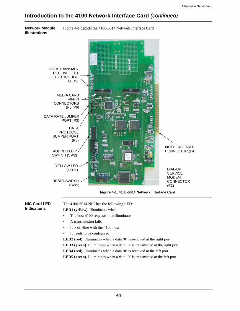
Chapter 4 Networking
Introduction to the 4100 Network Interface Card (continued)
Network Module Illustrations
Figure 4-1 depicts the 4100-6014 Network Interface Card.
Figure 4-1. 4100-6014 Network Interface Card
NIC Card LED Indications
The 4100-6014 NIC has the following LEDs:
LED1 (yellow). Illuminates when
• The host 4100 requests it to illuminate
• A transmission fails
• It is off-line with the 4100 host
• It needs to be configured
LED2 (red). Illuminates when a data ‘0’ is received at the right port.
LED3 (green). Illuminates when a data ‘0’ is transmitted at the right port.
LED4 (red). Illuminates when a data ‘0’ is received at the left port.
LED5 (green). Illuminates when a data ‘0’ is transmitted at the left port.
DATA TRANSMIT/ RECEIVE LEDs
(LED2 THROUGH LED5)
MEDIA CARD40-PIN
CONNECTORS (P5, P6)
DATA RATE JUMPER PORT (P3)
DATA PROTOCOL
JUMPER PORT (P3)
ADDRESS DIP SWITCH (SW2)
DIAL-UPSERVICEMODEMCONNECTOR (P2)
RESET SWITCH (SW1)
MOTHERBOARD CONNECTOR (P4)
YELLOW LED (LED1)
4-3
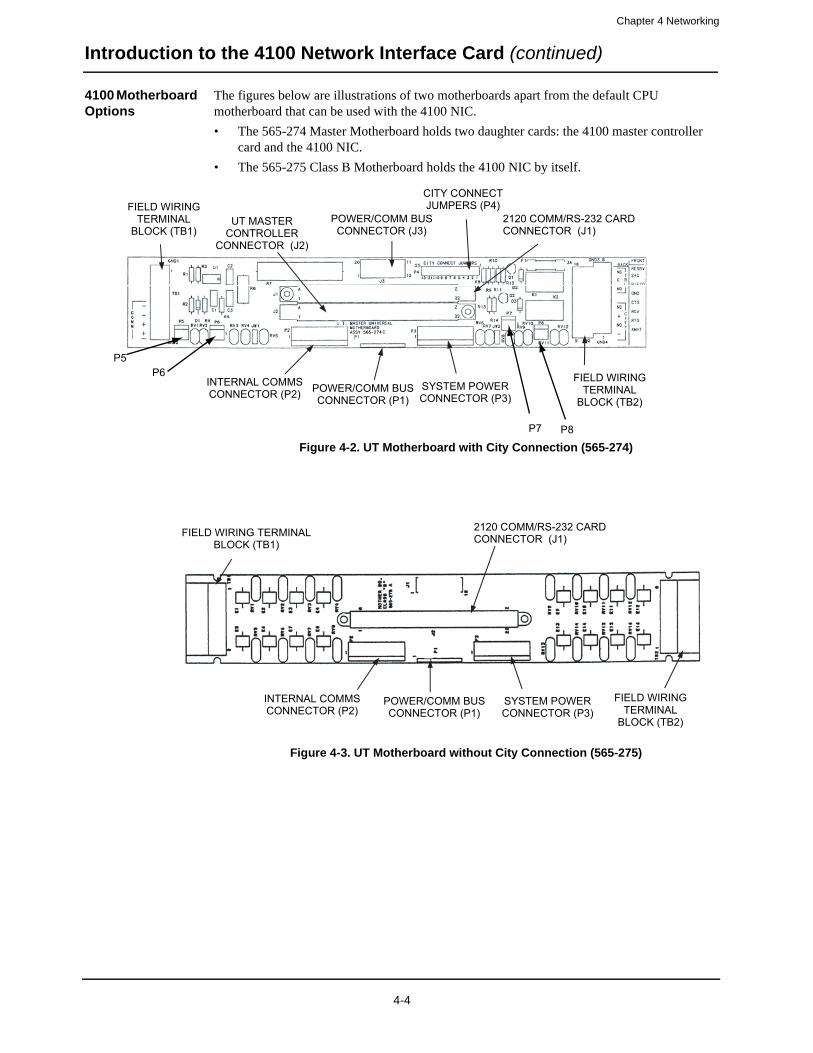
Chapter 4 Networking
Introduction to the 4100 Network Interface Card (continued)
4100 Motherboard Options
The figures below are illustrations of two motherboards apart from the default CPU motherboard that can be used with the 4100 NIC.
• The 565-274 Master Motherboard holds two daughter cards: the 4100 master controller card and the 4100 NIC.
• The 565-275 Class B Motherboard holds the 4100 NIC by itself.
Figure 4-2. UT Motherboard with City Connection (565-274)
Figure 4-3. UT Motherboard without City Connection (565-275)
POWER/COMM BUS CONNECTOR (J3)
2120 COMM/RS-232 CARD CONNECTOR (J1)
SYSTEM POWER CONNECTOR (P3)
INTERNAL COMMS CONNECTOR (P2)
UT MASTER CONTROLLER
CONNECTOR (J2)
POWER/COMM BUS CONNECTOR (P1)
FIELD WIRING TERMINAL
BLOCK (TB1)
FIELD WIRING TERMINAL
BLOCK (TB2)
CITY CONNECT JUMPERS (P4)
P5P6
P7 P8
SYSTEM POWER CONNECTOR (P3)
INTERNAL COMMS CONNECTOR (P2)
POWER/COMM BUS CONNECTOR (P1)
FIELD WIRING TERMINAL BLOCK (TB1)
FIELD WIRING TERMINAL
BLOCK (TB2)
2120 COMM/RS-232 CARD CONNECTOR (J1)
4-4
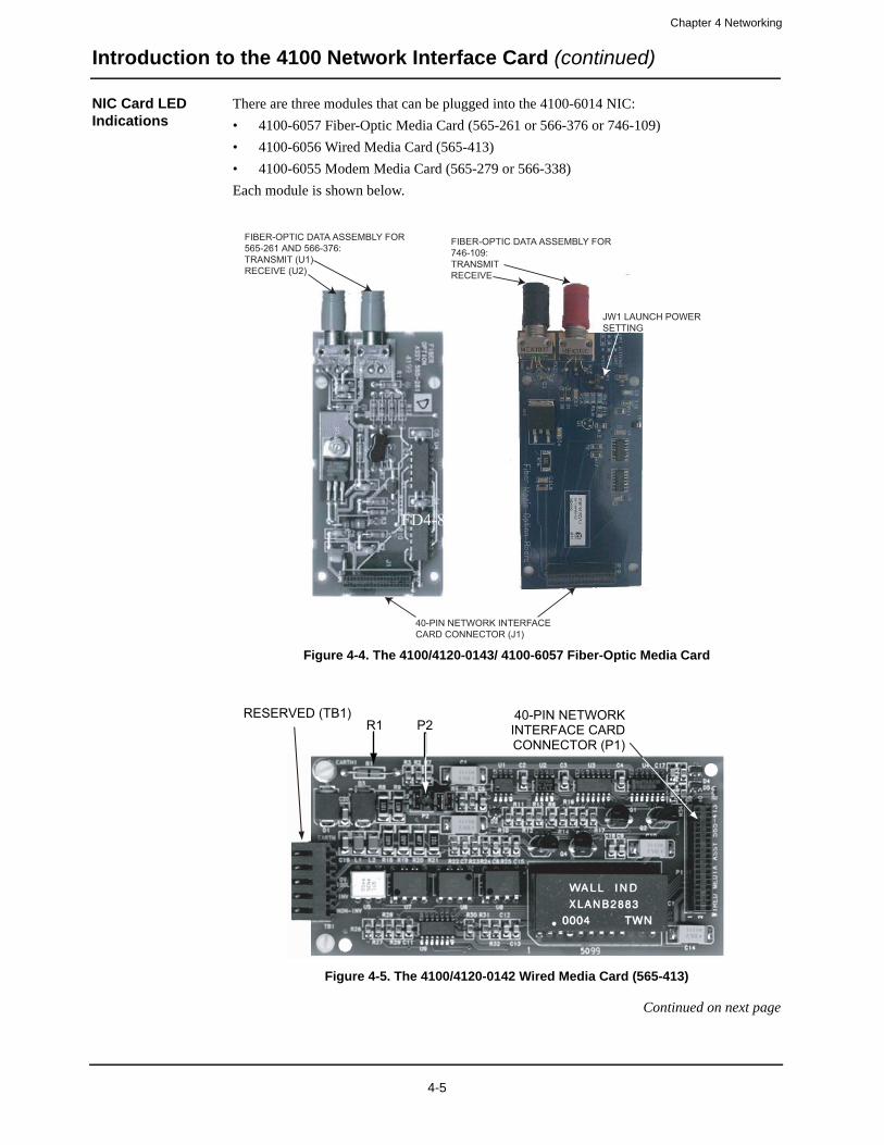
Chapter 4 Networking
Introduction to the 4100 Network Interface Card (continued)
NIC Card LED Indications
There are three modules that can be plugged into the 4100-6014 NIC:
• 4100-6057 Fiber-Optic Media Card (565-261 or 566-376 or 746-109)
• 4100-6056 Wired Media Card (565-413)
• 4100-6055 Modem Media Card (565-279 or 566-338)
Each module is shown below.
Figure 4-4. The 4100/4120-0143/ 4100-6057 Fiber-Optic Media Card
Figure 4-5. The 4100/4120-0142 Wired Media Card (565-413)
Continued on next page
FIBER-OPTIC DATA ASSEMBLY FOR565-261 AND 566-376:TRANSMIT (U1)RECEIVE (U2)
FIBER-OPTIC DATA ASSEMBLY FOR746-109:TRANSMIT RECEIVE
40-PIN NETWORK INTERFACECARD CONNECTOR (J1)
JW1 LAUNCH POWERSETTING
RESERVED (TB1) 40-PIN NETWORK INTERFACE CARD CONNECTOR (P1)
R1 P2
4-5

Chapter 4 Networking
Introduction to the 4100 Network Interface Card (continued)
NIC Card LED Indications
Figure 4-6. The 4100-6055 Modem Media Card (565-279 or 566-338)
Requirements and Limitations
Refer to Table 6-1 for electrical environmental requirements for the 4100 NIC and media cards.
RJ-11CONNECTOR (P3)
RS-232CONNECTOR (P1) (USED FOR PHYSICALBRIDGE)
DATA TRANSMISSION JUMPER PORT
(P4)
MODEM TYPE JUMPER PORT
(P5)
STATUS LEDs (LED1, LED2)
40-PIN NETWORK INTERFACE CARD CONNECTOR (J1)
Table 4-1. Electrical and Environmental Specifications
Electrical SpecificationsNetwork Interface Card Startup, no media cards: 8 VDC @ 110 mA
565-516 Nominal, no media cards: 20 to 32 VDC @ 0 mA
Network Interface Card 566-793
Nominal, no media cards: 20 to 32 VDC @ 46 mA
Modem Media Card 5 VDC @ 180 mA max.
Fiber Using 24 VDC power supply: 20 VDC @ 140 mA max.
Media Card Using 5 V power supply (GCC/NPU): 5 VDC @ 130 mA max.
Wired Media Card 4.75 to 5.25 VDC @ 170 mA max.
Environmental Specifications (All Modules)
Operating Temperature 32o F to 120 oF (0oC× to 49oC)
Humidity 10% to 93% relative humidity at 90 oF (32 oC)
4-6
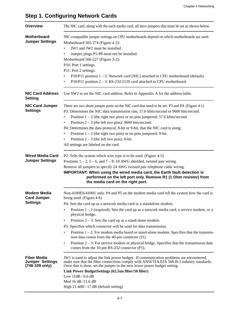
Chapter 4 Networking
Step 1. Configuring Network Cards
Overview The NIC card, along with the each media card, all have jumpers that must be set as shown below.
Motherboard Jumper Settings
NIC-compatible jumper settings on CPU motherboards depend on which motherboards are used.
Motherboard 565-274 (Figure 4-2):
• JW1 and JW2 must be installed.
• Jumper plugs P5-P8 must not be installed.
Motherboard 566-227 (Figure 3-2):
P10: Port 1 settings.
P11: Port 2 settings.
• P10/P11 position 1 – 2: Network card (NIC) attached to CPU motherboard (default).
• P10/P11 position 2 – 3: RS-232/2120 card attached to CPU motherboard.
NIC Card Address Setting
Use SW2 to set the NIC card address. Refer to Appendix A for the address table.
NIC Card Jumper Settings
There are two shunt jumper ports on the NIC card that need to be set: P3 and P4. (Figure 4-1)
P3: Determines the NIC data transmission rate, 57.6 kbits/second or 9600 bits/second.
• Position 1 – 2 (the right two pins) or no pins jumpered: 57.6 kbits/second.
• Position 2 – 3 (the left two pins): 9600 bits/second.
P4: Determines the data protocol, 8-bit or 9-bit, that the NIC card is using.
• Position 1 – 2 (the right two pins) or no pins jumpered: 9-bit.
• Position 2 – 3 (the left two pins): 8-bit.
All settings are labeled on the card.
Wired Media Card Jumper Settings
P2: Tells the system which wire type is to be used. (Figure 4-5)
Positions 1 – 2, 5 – 6, and 7 – 8: 18 AWG shielded, twisted pair wiring.
Remove all jumpers to specify 24 AWG twisted pair telephone cable wiring.
IMPORTANT: When using the wired media card, the Earth fault detection is performed on the left port only. Remove R1 (1 Ohm resistor) from the media card on the right port.
Modem Media Card Jumper Settings
Non-4100ES/4100U only. P4 and P5 on the modem media card tell the system how the card is being used. (Figure 4-6)
P4: Sets the card up as a network media card or a standalone modem.
• Position 1 – 2 (required): Sets the card up as a network media card, a service modem, or a physical bridge.
• Position 2 – 3: Sets the card up as a stand-alone modem.
P5: Specifies which connector will be used for data transmission.
• Position 1 – 2: For modem media board or stand-alone modem. Specifies that the transmis-sion data comes from the 40-pin connector (J1).
• Position 2 – 3: For service modem or physical bridge. Specifies that the transmission data comes from the 10-pin RS-232 connector (P1).
Fiber Media Jumper Settings (746-109 only)
JW1 is used to adjust the link power budget. If communication problems are encountered, make sure that the fiber connections comply with ANSI/TIA/EIA 568-B-3 industry standards. Once that is done, set the jumper to the next lower power budget setting.
Link Power BudgetSettings (62.5un fiber/50 fiber)Low 11dB / 6.6 dBMed 16 dB /11.6 dBHigh 21.4dB / 17 dB (default setting)
4-7
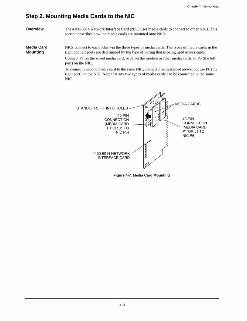
Chapter 4 Networking
Step 2. Mounting Media Cards to the NIC
Overview The 4100-6014 Network Interface Card (NIC) uses media cards to connect to other NICs. This section describes how the media cards are mounted onto NICs.
Media Card Mounting
NICs connect to each other via the three types of media cards. The types of media cards in the right and left ports are determined by the type of wiring that is being used across cards.
Connect P1 on the wired media card, or J1 on the modem or fiber media cards, to P5 (the left port) on the NIC.
To connect a second media card to the same NIC, connect it as described above, but use P6 (the right port) on the NIC. Note that any two types of media cards can be connected to the same NIC.
Figure 4-7. Media Card Mounting
MEDIA CARDS
4100-6014 NETWORK INTERFACE CARD
40-PINCONNECTION (MEDIA CARD
P1 OR J1 TO NIC P5)
40-PINCONNECTION (MEDIA CARD P1 OR J1 TO NIC P6)
STANDOFFS FIT INTO HOLES
4-8
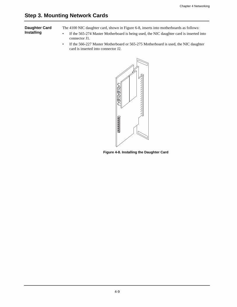
Chapter 4 Networking
Step 3. Mounting Network Cards
Daughter Card Installing
The 4100 NIC daughter card, shown in Figure 6-8, inserts into motherboards as follows:
• If the 565-274 Master Motherboard is being used, the NIC daughter card is inserted into connector J1.
• If the 566-227 Master Motherboard or 565-275 Motherboard is used, the NIC daughter card is inserted into connector J2.
Figure 4-8. Installing the Daughter Card
4-9

Chapter 4 Networking
Step 4. Wiring Network Cards
Overview The nodes in the network now have to be wired together, so that the NIC in one host panel connects to the NIC in the next panel. This section contains guidelines and instructions for NIC wiring.
Wiring Guidelines Refer to the following guidelines whenever field wiring the NICs.
• Network nodes must be wired right to left port, regardless of the media type selected.
• Style 7 protection is achieved by wiring the nodes in a loop fashion. A single fault (except an Earth fault) will cause the network to reconfigure for degraded Style 7 (Style 4) operation. A second fault (except an Earth fault) will result in the network dividing into two separate networks.
• Style 4 is achieved by wiring the nodes in a linear fashion. Style 4 networks are not fault-tolerant and a single fault (except an Earth fault) will result in the network dividing into two separate networks.
• Earth fault detection is performed on the left port only. When a network Earth fault occurs, the trouble is only reported on the node whose left port is connected to the span.
• All 18 AWG (0.8231 mm2) wiring used with 4100-6056 Wired Media Cards must be twisted-shielded pair. All 24 AWG (0.2047 mm2) (telephone cable) used with 4100-6056 must be twisted pair. When shielded cable is used, the shield must be terminated to chassis Earth on the left port only.
• It is permissible to use mixed media in a network. For example, some spans may be “wired media” while others are optical fiber or telephone modem.
• Each NIC has a jumper for selecting between network data rates of 57.6 kbps and
• 9.6 kbps. All cards in the network must be set for the same rate. (When modem media or physical bridging is used, the data rate must be set for 9.6 kbps).
• Each NIC has a jumper for selecting between 8- and 9-bit network protocols. All cards in the network must be set for the same network protocol. (When modem media or physical bridging is used, the protocol must be set for 8-bit).
• All network wiring except the shield is supervised and power limited.
• When wiring leaves the building, 2081-9044 Overvoltage Protectors are required. One overvoltage protector is installed where wiring leaves the building; another is installed where wiring enters the next building.
Continued on next page
4-10
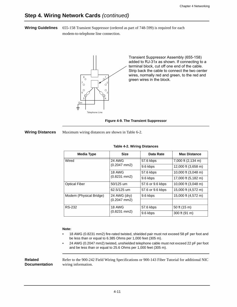
Chapter 4 Networking
Step 4. Wiring Network Cards (continued)
Wiring Guidelines 655-158 Transient Suppressor (ordered as part of 748-599) is required for each
modem-to-telephone line connection.
Figure 4-9. The Transient Suppressor
Wiring Distances Maximum wiring distances are shown in Table 6-2.
Note:
• 18 AWG (0.8231 mm2) fire-rated twisted, shielded pair must not exceed 58 pF per foot and be less than or equal to 6.385 Ohms per 1,000 feet (305 m).
• 24 AWG (0.2047 mm2) twisted, unshielded telephone cable must not exceed 22 pF per foot and be less than or equal to 25.6 Ohms per 1,000 feet (305 m).
Related Documentation
Refer to the 900-242 Field Wiring Specifications or 900-143 Fiber Tutorial for additional NIC wiring information.
8
5
Grn
Telephone Line
1
4
7
6
2
3
Transient Suppressor Assembly (655-158) added to RJ-31x as shown. If connecting to a terminal block, cut off one end of the cable. Strip back the cable to connect the two center wires, normally red and green, to the red and green wires in the block.
Table 4-2. Wiring Distances
Media Type Size Data Rate Max Distance
Wired 24 AWG(0.2047 mm2)
57.6 kbps 7,000 ft (2,134 m)
9.6 kbps 12,000 ft (3,658 m)
18 AWG(0.8231 mm2)
57.6 kbps 10,000 ft (3,048 m)
9.6 kbps 17,000 ft (5,182 m)
Optical Fiber 50/125 um 57.6 or 9.6 kbps 10,000 ft (3,048 m)
62.5/125 um 57.6 or 9.6 kbps 15,000 ft (4,572 m)
Modem (Physical Bridge) 24 AWG (dry)(0.2047 mm2)
9.6 kbps 15,000 ft (4,572 m)
RS-232 18 AWG(0.8231 mm2)
57.6 kbps 50 ft (15 m)
9.6 kbps 300 ft (91 m)
4-11
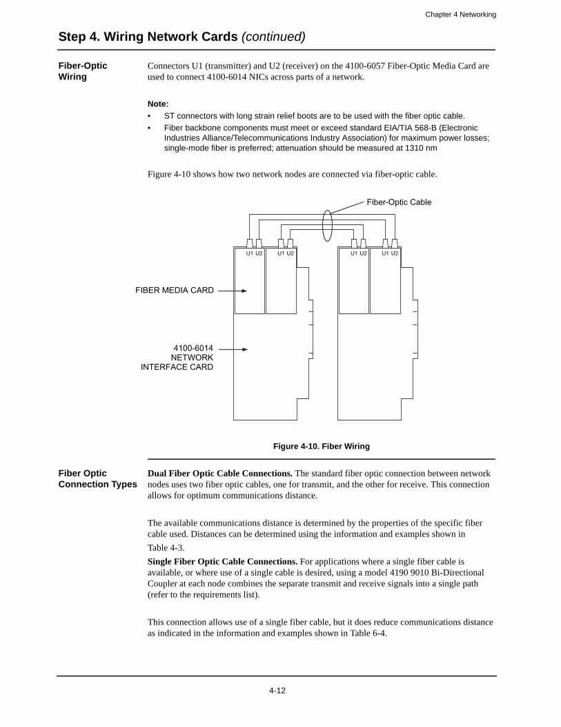
Chapter 4 Networking
Step 4. Wiring Network Cards (continued)
Fiber-Optic Wiring
Connectors U1 (transmitter) and U2 (receiver) on the 4100-6057 Fiber-Optic Media Card are used to connect 4100-6014 NICs across parts of a network.
Note:
• ST connectors with long strain relief boots are to be used with the fiber optic cable.
• Fiber backbone components must meet or exceed standard EIA/TIA 568-B (Electronic Industries Alliance/Telecommunications Industry Association) for maximum power losses; single-mode fiber is preferred; attenuation should be measured at 1310 nm
Figure 4-10 shows how two network nodes are connected via fiber-optic cable.
Figure 4-10. Fiber Wiring
Fiber Optic Connection Types
Dual Fiber Optic Cable Connections. The standard fiber optic connection between network nodes uses two fiber optic cables, one for transmit, and the other for receive. This connection allows for optimum communications distance.
The available communications distance is determined by the properties of the specific fiber cable used. Distances can be determined using the information and examples shown in
Table 4-3.
Single Fiber Optic Cable Connections. For applications where a single fiber cable is available, or where use of a single cable is desired, using a model 4190 9010 Bi-Directional Coupler at each node combines the separate transmit and receive signals into a single path (refer to the requirements list).
This connection allows use of a single fiber cable, but it does reduce communications distance as indicated in the information and examples shown in Table 6-4.
U1 U2 U1 U2 U1 U2 U1 U2
FIBER MEDIA CARD
4100-6014 NETWORK
INTERFACE CARD
Fiber-Optic Cable
4-12
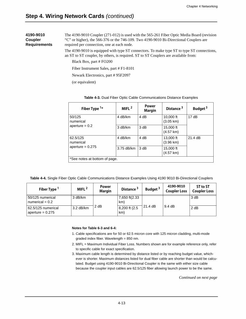
Chapter 4 Networking
Step 4. Wiring Network Cards (continued)
4190-9010 Coupler Requirements
The 4190-9010 Coupler (271-012) is used with the 565-261 Fiber Optic Media Board (revision “C” or higher), the 566-376 or the 746-109. Two 4190-9010 Bi-Directional Couplers are required per connection, one at each node.
The 4190-9010 is equipped with type ST connectors. To make type ST to type ST connections, an ST to ST coupler, by others, is required. ST to ST Couplers are available from:
Black Box, part # FO200
Fiber Instrument Sales, part # F1-8101
Newark Electronics, part # 95F2097
(or equivalent)
Notes for Table 6-3 and 6-4:
1. Cable specifications are for 50 or 62.5 micron core with 125 micron cladding, multi-mode
graded index fiber. Wavelength = 850 nm.
2. MIFL = Maximum Individual Fiber Loss. Numbers shown are for example reference only, refer
to specific cable for exact specification.
3. Maximum cable length is determined by distance listed or by reaching budget value, which-
ever is shorter. Maximum distances listed for dual fiber cable are shorter than would be calcu-
lated. Budget using 4190-9010 Bi-Directional Coupler is the same with either size cable
because the coupler input cables are 62.5/125 fiber allowing launch power to be the same.
Continued on next page
Table 4-3. Dual Fiber Optic Cable Communications Distance Examples
Fiber Type 1* MIFL 2Power Margin Distance 3 Budget 3
50/125numericalaperture = 0.2
4 dB/km 4 dB 10,000 ft (3.05 km)
17 dB
3 dB/km 3 dB 15,000 ft (4.57 km)
62.5/125numericalaperture = 0.275
4 dB/km 4 dB 13,000 ft (3.96 km)
21.4 dB
3.75 dB/km 3 dB 15,000 ft (4.57 km)
*See notes at bottom of page.
Table 4-4. Single Fiber Optic Cable Communications Distance Examples Using 4190 9010 Bi-Directional Couplers
Fiber Type 1 MIFL 2Power Margin Distance 3 Budget 3
4190-9010 Coupler Loss
ST to ST Coupler Loss
50/125 numerical numerical = 0.2
3 dB/km
2 dB
7,650 ft(2.33 km)
21.4 dB 9.4 dB
3 dB
62.5/125 numerical aperture = 0.275
3.2 dB/km 8,200 ft (2.5 km)
2 dB
4-13
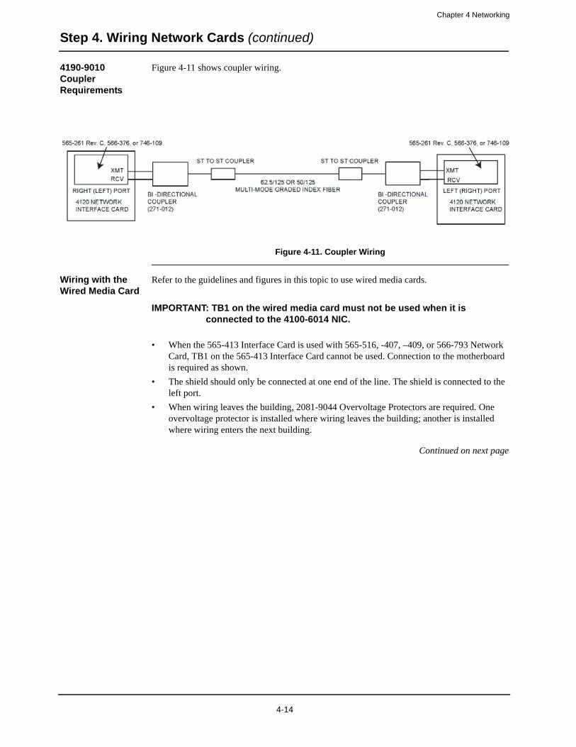
Chapter 4 Networking
Step 4. Wiring Network Cards (continued)
4190-9010 Coupler Requirements
Figure 4-11 shows coupler wiring.
Figure 4-11. Coupler Wiring
Wiring with the Wired Media Card
Refer to the guidelines and figures in this topic to use wired media cards.
IMPORTANT: TB1 on the wired media card must not be used when it is connected to the 4100-6014 NIC.
• When the 565-413 Interface Card is used with 565-516, -407, –409, or 566-793 Network Card, TB1 on the 565-413 Interface Card cannot be used. Connection to the motherboard is required as shown.
• The shield should only be connected at one end of the line. The shield is connected to the left port.
• When wiring leaves the building, 2081-9044 Overvoltage Protectors are required. One overvoltage protector is installed where wiring leaves the building; another is installed where wiring enters the next building.
Continued on next page
FD4-848-1
4-14
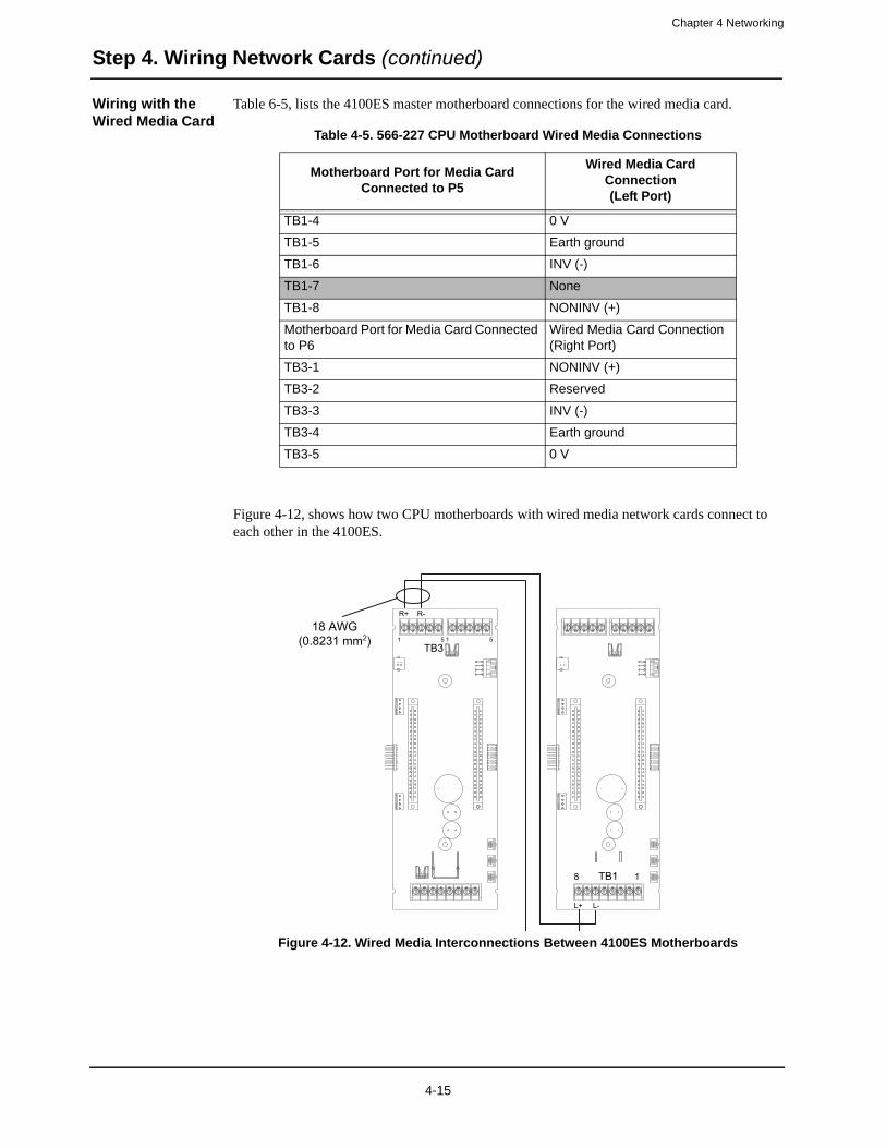
Chapter 4 Networking
Step 4. Wiring Network Cards (continued)
Wiring with the Wired Media Card
Table 6-5, lists the 4100ES master motherboard connections for the wired media card.
Figure 4-12, shows how two CPU motherboards with wired media network cards connect to each other in the 4100ES.
Figure 4-12. Wired Media Interconnections Between 4100ES Motherboards
Table 4-5. 566-227 CPU Motherboard Wired Media Connections
Motherboard Port for Media Card Connected to P5
Wired Media Card Connection(Left Port)
TB1-4 0 V
TB1-5 Earth ground
TB1-6 INV (-)
TB1-7 None
TB1-8 NONINV (+)
Motherboard Port for Media Card Connected to P6
Wired Media Card Connection (Right Port)
TB3-1 NONINV (+)
TB3-2 Reserved
TB3-3 INV (-)
TB3-4 Earth ground
TB3-5 0 V
18 AWG(0.8231 mm2) 5151
TB3
R+ R-
8 TB1 1
L+ L-
4-15

Chapter 4 Networking
Step 4. Wiring Network Cards (continued)
Modem Guidelines
Review the following guidelines before wiring a network with modem media boards.
• Modem media wiring for NICs applies to non-4100ES/4100U systems only.
• Phone Line Classification consists of the following:
- Private leased line for analog data communications- No dial tone- Full duplex operation- No conditioning required- No signaling required- Two-wire line interface- RJ-11 modular jack
• If a four-wire circuit is required, the line must include a data station termination (DST) device to provide the two-wire interface required by the 4120 network modem. The DST device should be located as close to the FACP as possible to minimize dry line signal losses.
• The modem is capable of full duplex V.32bis analog data communications. The transmit signal level is 10 dbm.
• Telecommunications device: Xecom Model XE1414 or XE1414C V.32bis Two-Wire Analog Modem
• Modem FCC Registration Number: DWEUSA-75322-FA-E (565-279); DWEUSA-35610-M5-E (566-338)
Modem Wiring
The Modem Media Card uses RJ-11 connectors to connect 4100-6014 NIC Assemblies across parts of a network.
Use the RJ-11 connector (P2) to connect nodes that use the modem media card. Do not use connector P1 (P1 is reserved for when the daughter card is used as a physical bridge). Leased lines must be analog, full-duplex, private line (no dial tone), with a two-wire RJ-11 interface. Style 4 requires one circuit; Style 7 requires two circuits.
Figure 4-13. Modem Wiring
IMPORTANT: Modem media wiring for NICs applies to non-4100ES/4100U systems only. .
P3 P3 P3 P3
MODEM MEDIA CARD
4100-6014 NETWORK
INTERFACE CARD
Standard TELCO Cable
4-16
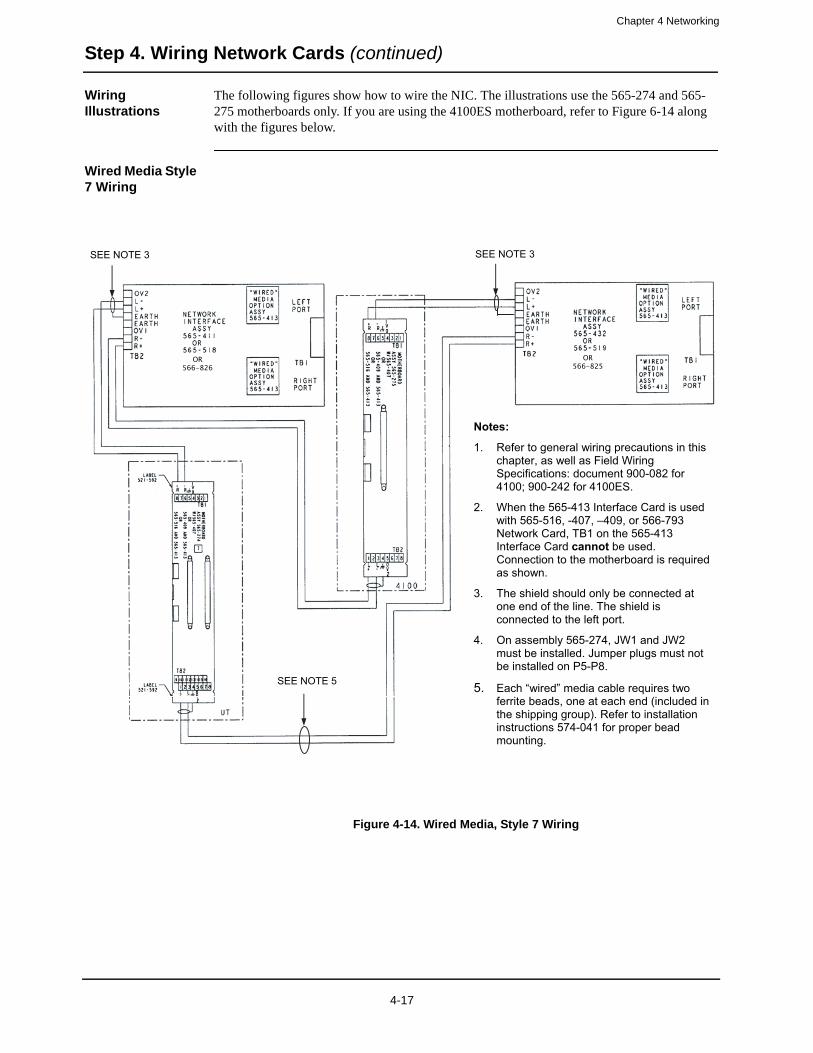
Chapter 4 Networking
Step 4. Wiring Network Cards (continued)
Wiring Illustrations
The following figures show how to wire the NIC. The illustrations use the 565-274 and 565-275 motherboards only. If you are using the 4100ES motherboard, refer to Figure 6-14 along with the figures below.
Wired Media Style 7 Wiring
Figure 4-14. Wired Media, Style 7 Wiring
Notes:
1. Refer to general wiring precautions in this chapter, as well as Field Wiring Specifications: document 900-082 for 4100; 900-242 for 4100ES.
2. When the 565-413 Interface Card is used with 565-516, -407, –409, or 566-793 Network Card, TB1 on the 565-413 Interface Card cannot be used. Connection to the motherboard is required as shown.
3. The shield should only be connected at one end of the line. The shield is connected to the left port.
4. On assembly 565-274, JW1 and JW2 must be installed. Jumper plugs must not be installed on P5-P8.
5. Each “wired” media cable requires two ferrite beads, one at each end (included in the shipping group). Refer to installation instructions 574-041 for proper bead mounting.
SEE NOTE 3
SEE NOTE 5
SEE NOTE 3
OR566-826
OR566-825
4-17
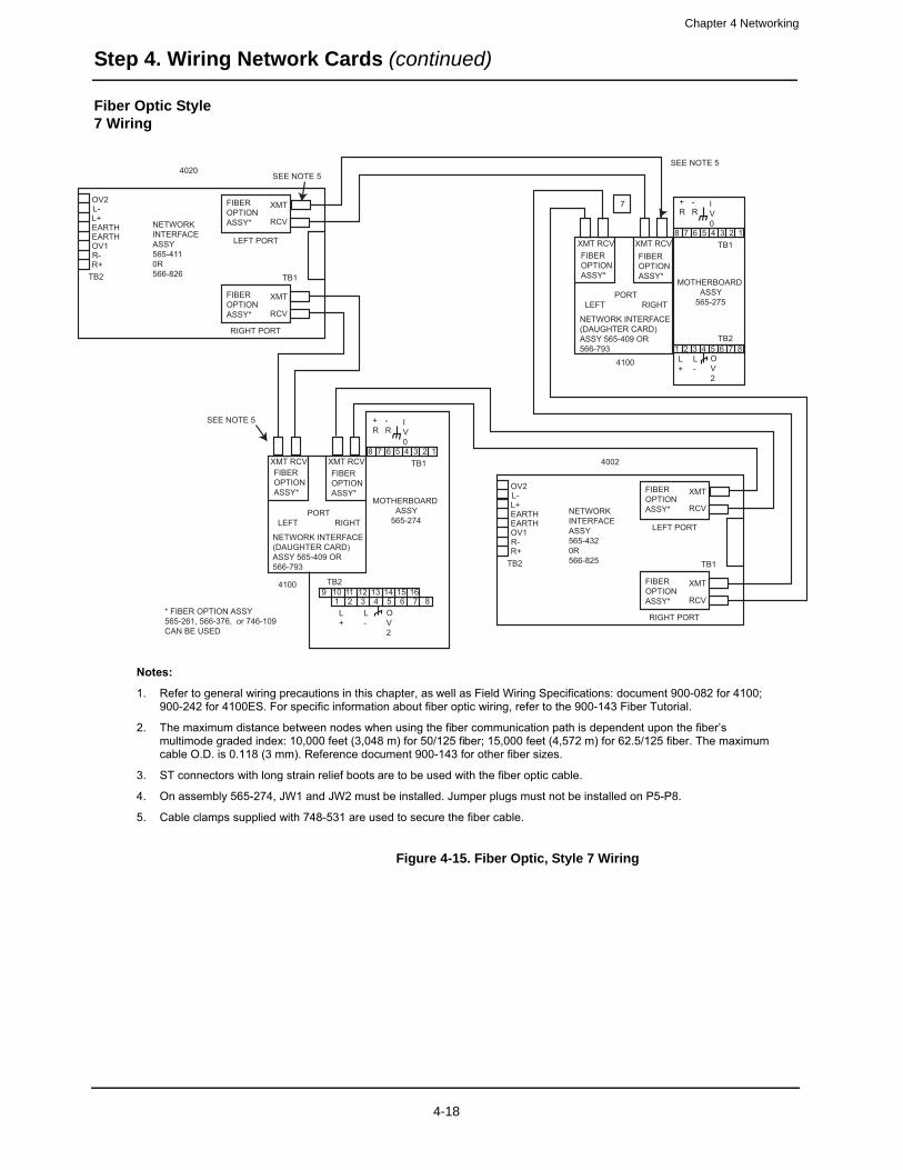
Chapter 4 Networking
Step 4. Wiring Network Cards (continued)
Fiber Optic Style 7 Wiring
Figure 4-15. Fiber Optic, Style 7 Wiring
FD4-848-2
Notes:
1. Refer to general wiring precautions in this chapter, as well as Field Wiring Specifications: document 900-082 for 4100; 900-242 for 4100ES. For specific information about fiber optic wiring, refer to the 900-143 Fiber Tutorial.
2. The maximum distance between nodes when using the fiber communication path is dependent upon the fiber’s multimode graded index: 10,000 feet (3,048 m) for 50/125 fiber; 15,000 feet (4,572 m) for 62.5/125 fiber. The maximum cable O.D. is 0.118 (3 mm). Reference document 900-143 for other fiber sizes.
3. ST connectors with long strain relief boots are to be used with the fiber optic cable.
4. On assembly 565-274, JW1 and JW2 must be installed. Jumper plugs must not be installed on P5-P8.
5. Cable clamps supplied with 748-531 are used to secure the fiber cable.
OV2L-L+EARTHEARTHOV1R-R+
TB2
NETWORKINTERFACEASSY565-4110R566-826
FIBEROPTIONASSY*
FIBEROPTIONASSY*
FIBEROPTIONASSY*
XMT
XMT
XMT
RCV
RCVFIBEROPTIONASSY*
XMT RCV
RCV
LEFT PORT
RIGHT PORT
TB1
PORTLEFT RIGHT
NETWORK INTERFACE(DAUGHTER CARD)ASSY 565-409 OR566-793
4100
FIBEROPTIONASSY*
XMT RCVFIBEROPTIONASSY*
XMT RCV
PORTLEFT RIGHT
NETWORK INTERFACE(DAUGHTER CARD)ASSY 565-409 OR566-793
4100
4020
OV2L-L+EARTHEARTHOV1R-R+
TB2
NETWORKINTERFACEASSY565-4320R566-825
FIBEROPTIONASSY*
FIBEROPTIONASSY*
XMT
XMT
RCV
RCV
LEFT PORT
RIGHT PORT
TB1
4002
TB1
TB2
MOTHERBOARD ASSY 565-275
8
8
7
7
6
6
5
5
4
4
3
3
2
2
1
1L-
L+
+R
-R
IV0
OV2
TB1
TB2
MOTHERBOARD ASSY 565-274
8
8
7
7
6
6
5
5
4
4
3
3
2
2
1
1L-
L+
+R
-R
IV0
OV2
9 10 11 12 13 14 15 16
7
* FIBER OPTION ASSY565-261, 566-376, or 746-109 CAN BE USED
SEE NOTE 5
SEE NOTE 5
SEE NOTE 5
4-18
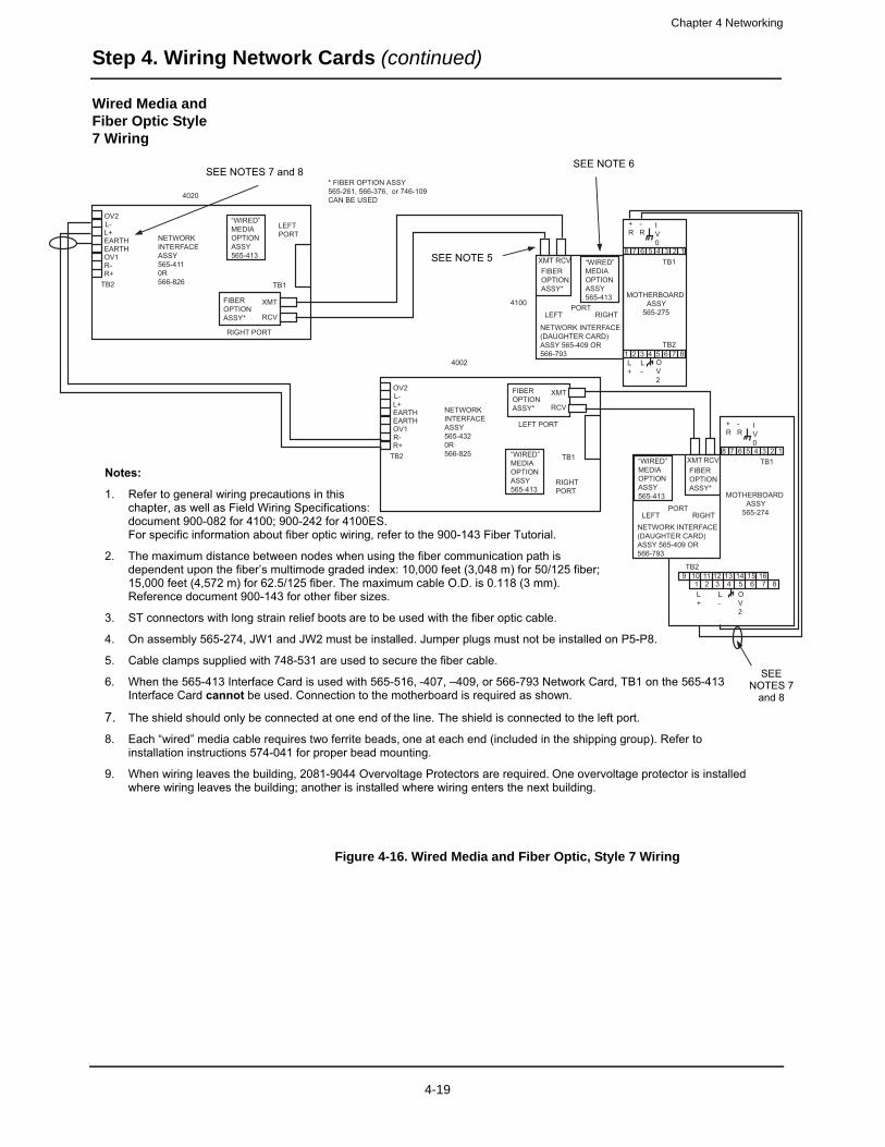
Chapter 4 Networking
Step 4. Wiring Network Cards (continued)
Wired Media and Fiber Optic Style 7 Wiring
Figure 4-16. Wired Media and Fiber Optic, Style 7 Wiring
FD4-848-3
Notes:
1. Refer to general wiring precautions in this chapter, as well as Field Wiring Specifications: document 900-082 for 4100; 900-242 for 4100ES. For specific information about fiber optic wiring, refer to the 900-143 Fiber Tutorial.
2. The maximum distance between nodes when using the fiber communication path is dependent upon the fiber’s multimode graded index: 10,000 feet (3,048 m) for 50/125 fiber; 15,000 feet (4,572 m) for 62.5/125 fiber. The maximum cable O.D. is 0.118 (3 mm). Reference document 900-143 for other fiber sizes.
3. ST connectors with long strain relief boots are to be used with the fiber optic cable.
4. On assembly 565-274, JW1 and JW2 must be installed. Jumper plugs must not be installed on P5-P8.
5. Cable clamps supplied with 748-531 are used to secure the fiber cable.
6. When the 565-413 Interface Card is used with 565-516, -407, –409, or 566-793 Network Card, TB1 on the 565-413 Interface Card cannot be used. Connection to the motherboard is required as shown.
7. The shield should only be connected at one end of the line. The shield is connected to the left port.
8. Each “wired” media cable requires two ferrite beads, one at each end (included in the shipping group). Refer to installation instructions 574-041 for proper bead mounting.
9. When wiring leaves the building, 2081-9044 Overvoltage Protectors are required. One overvoltage protector is installed where wiring leaves the building; another is installed where wiring enters the next building.
SEE NOTE 5
SEE NOTE 6 SEE NOTES 7 and 8
SEENOTES 7
and 8
OV2L-L+EARTHEARTHOV1R-R+
TB2
NETWORKINTERFACEASSY565-4110R566-826
FIBEROPTIONASSY*
XMT
RCV
LEFTPORT
RIGHT PORT
TB1
XMT
4020
OV2L-L+EARTHEARTHOV1R-R+
TB2
NETWORKINTERFACEASSY565-4320R566-825
FIBEROPTIONASSY*
XMT
RCV
LEFT PORT
RIGHTPORT
TB1
4002
* FIBER OPTION ASSY565-261, 566-376, or 746-109 CAN BE USED
“WIRED”MEDIAOPTIONASSY565-413
“WIRED”MEDIAOPTIONASSY565-413
“WIRED”MEDIAOPTIONASSY565-413
“WIRED”MEDIAOPTIONASSY565-413
FIBEROPTIONASSY*
RCV
PORTLEFT RIGHT
NETWORK INTERFACE(DAUGHTER CARD)ASSY 565-409 OR566-793
TB1
TB2
MOTHERBOARD ASSY 565-274
8
8
7
7
6
6
5
5
4
4
3
3
2 1
L-
+R
-R
IV0
OV2
12 13 14 15 16
FIBEROPTIONASSY*
XMT RCV
PORTLEFT RIGHT
NETWORK INTERFACE(DAUGHTER CARD)ASSY 565-409 OR566-793
4100
TB1
TB2
MOTHERBOARD ASSY 565-275
8
8
7
7
6
6
5
5
4
4
3
3
2
2
1
1L-
L+
L+
+R
-R
IV0
OV2
9 10 111 2
4-19
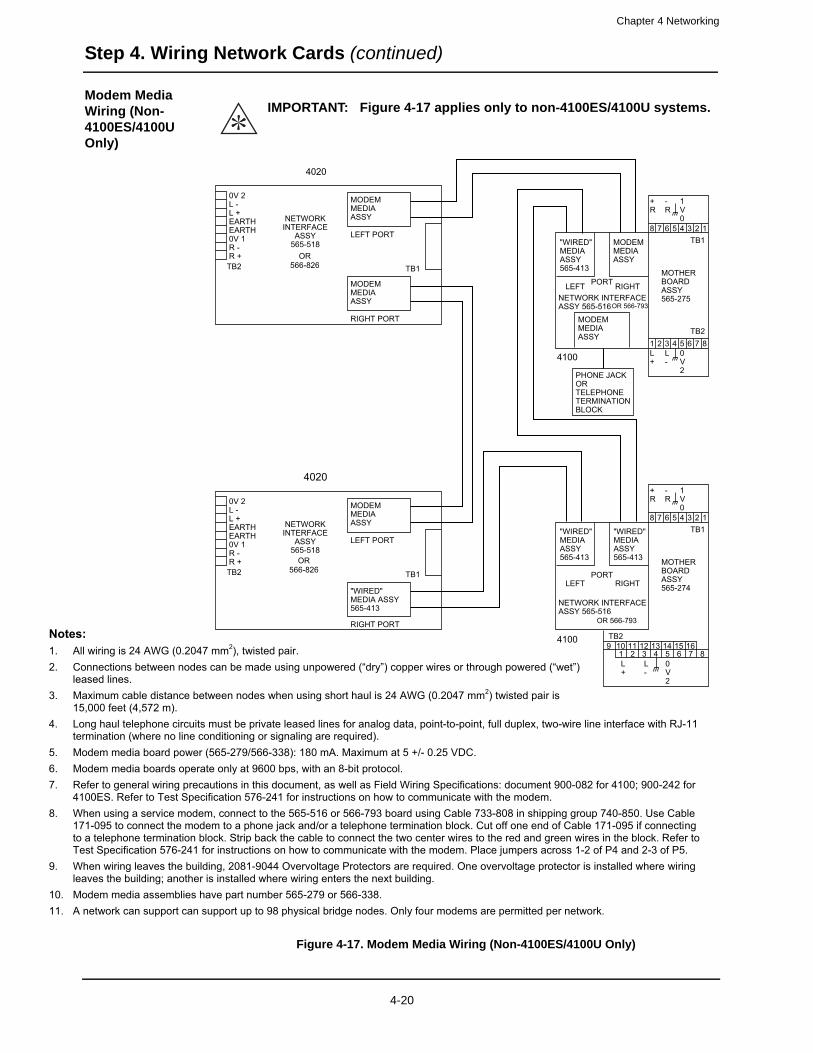
Chapter 4 Networking
Note1. A2. C
l3. M
14. L
t5. M6. M7. R
48. W
1tT
9. Wl
10. M11. A
Step 4. Wiring Network Cards (continued)
Modem Media Wiring (Non-4100ES/4100U Only)
Figure 4-17. Modem Media Wiring (Non-4100ES/4100U Only)
IMPORTANT: Figure 4-17 applies only to non-4100ES/4100U systems.
0V 2L -L +EARTH NETWORK
INTERFACEASSY
565-518
4020
MODEMMEDIAASSY
LEFT PORTEARTH0V 1R -R +TB2
MODEMMEDIAASSY
RIGHT PORT
TB1
0V 2L -L +EARTH NETWORK
INTERFACEASSY
565-518
4020
MODEMMEDIAASSY
LEFT PORTEARTH0V 1R -R +TB2
"WIRED"MEDIA ASSY565-413
"WIRED"MEDIAASSY565-413
MODEMMEDIAASSY
MOTHERBOARDASSY565-275
8
MODEMMEDIAASSY
PHONE JACKORTELEPHONETERMINATIONBLOCK
4100
PORTLEFT RIGHTNETWORK INTERFACEASSY 565-516
RIGHT PORT
TB1
7 6 5 4
+R
-R
TB1
1V0
3 2 1
1 2 3 4 5L+
L-
TB2
0V2
6 7 8
"WIRED"MEDIAASSY565-413
"WIRED"MEDIAASSY565-413 MOTHER
BOARDASSY565-274
8
4100
PORTLEFT RIGHT
NETWORK INTERFACEASSY 565-516
7 6 5 4
+R
-R
TB1
1V0
3 2 1
9 10 11 12 13 14 15 161 2 3 4 5 6 7 8L+
L-
TB2
0V2
s:ll wiring is 24 AWG (0.2047 mm2), twisted pair. onnections between nodes can be made using unpowered (“dry”) copper wires or through powered (“wet”)
eased lines. aximum cable distance between nodes when using short haul is 24 AWG (0.2047 mm2) twisted pair is
5,000 feet (4,572 m). ong haul telephone circuits must be private leased lines for analog data, point-to-point, full duplex, two-wire line interface with RJ-11
ermination (where no line conditioning or signaling are required). odem media board power (565-279/566-338): 180 mA. Maximum at 5 +/- 0.25 VDC. odem media boards operate only at 9600 bps, with an 8-bit protocol. efer to general wiring precautions in this document, as well as Field Wiring Specifications: document 900-082 for 4100; 900-242 for 100ES. Refer to Test Specification 576-241 for instructions on how to communicate with the modem. hen using a service modem, connect to the 565-516 or 566-793 board using Cable 733-808 in shipping group 740-850. Use Cable
71-095 to connect the modem to a phone jack and/or a telephone termination block. Cut off one end of Cable 171-095 if connectingo a telephone termination block. Strip back the cable to connect the two center wires to the red and green wires in the block. Refer to est Specification 576-241 for instructions on how to communicate with the modem. Place jumpers across 1-2 of P4 and 2-3 of P5.hen wiring leaves the building, 2081-9044 Overvoltage Protectors are required. One overvoltage protector is installed where wiring
eaves the building; another is installed where wiring enters the next building. odem media assemblies have part number 565-279 or 566-338. network can support can support up to 98 physical bridge nodes. Only four modems are permitted per network.
OR566-826
OR566-826
OR 566-793
OR 566-793
4-20

Chapter 4 Networking
Network Audio Wiring
Head-End Audio Network Configuration
A “Head End” audio network usually contains one node with an audio controller module
(4100-1210 Analog Controller Board or 4100-1211 [or -1311] Digital Controller Board), and may contain local analog or digital amplifiers. Some configurations may have an audio controller module located in a non-head end node; for example, an application with backup local audio in a non-head end node or an application with distributed microphones.
Typically, the other nodes only contain amplifiers, the audio riser interface (4100-0621 Analog Audio Riser or 4100-0622 Digital Audio Riser), the 4100-0623 and the 4100-1341 Network Audio Riser Controller Module.
The 4100-0623 Network Audio Riser Controller Module supports audio interconnections when connected to 4100-0621 Analog Audio Risers or 4100-0622 Digital Audio Risers. It is a version of the Basic TIC that doesn’t have an RUI input. It communicates via internal slave communications and is used to control audio riser interface modules in network nodes that are stand-alone fire alarm control panels.
Locations on the Network Audio Riser Controller Module
Figure 4-18 shows the DIP switch, LED, and connector locations on the 4100-0623 Network Audio Riser Controller Module.
Figure 4-18. Network Audio Riser Controller Module
LED4
SW1
LED1
TB2
PRI
LED2
P1
P3
LED5
TB3
SECRUI
TMPR SW24C INPUT SHLD
4100COMMLOSSRUIG.F.
SEARCH
AUDIO RISER CARD
SW1. Baud rate/device address
DIP switch (see Appendix A)
LED1. Illuminates to indicate
communication loss with the CPU
P3. Audio riser connector
4-21
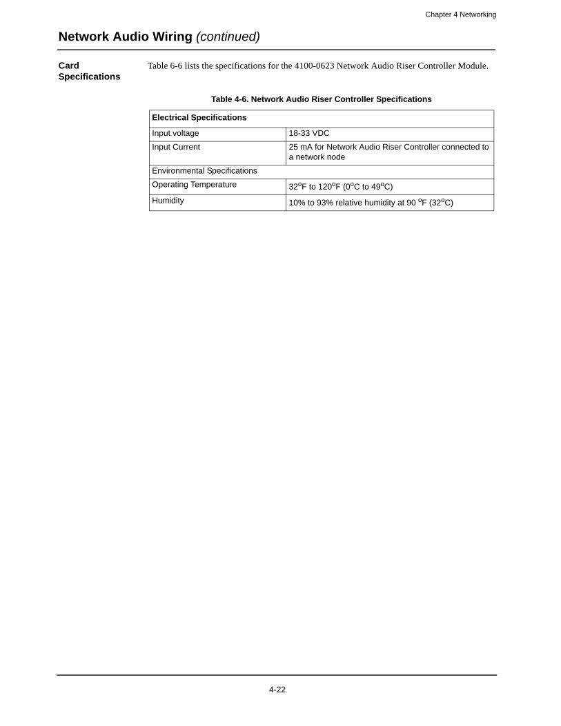
Chapter 4 Networking
Network Audio Wiring (continued)
Card Specifications
Table 6-6 lists the specifications for the 4100-0623 Network Audio Riser Controller Module.
Table 4-6. Network Audio Riser Controller Specifications
Electrical Specifications
Input voltage 18-33 VDC
Input Current 25 mA for Network Audio Riser Controller connected to a network node
Environmental Specifications
Operating Temperature 32oF to 120oF (0oC to 49oC)
Humidity 10% to 93% relative humidity at 90 oF (32oC)
4-22
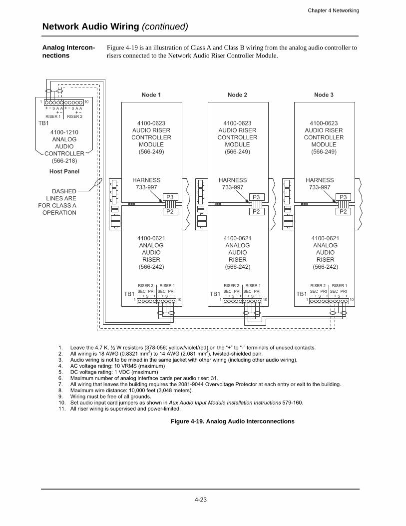
Chapter 4 Networking
Network Audio Wiring (continued)
Analog Intercon-nections
Figure 4-19 is an illustration of Class A and Class B wiring from the analog audio controller to risers connected to the Network Audio Riser Controller Module.
Figure 4-19. Analog Audio Interconnections
DASHEDLINES ARE
FOR CLASS AOPERATION
4100-0621ANALOGAUDIORISER
(566-242)
4100-1210ANALOGAUDIO
CONTROLLER(566-218)
TB1RISER 1
1 10
RISER 2
S A A S A A
HARNESS733-997
P3
P2
Node 1
Host Panel
Node 2 Node 3
4100-0623AUDIO RISERCONTROLLER
MODULE(566-249)
4100-0623AUDIO RISERCONTROLLER
MODULE(566-249)
4100-0623AUDIO RISERCONTROLLER
MODULE(566-249)
4100-0621ANALOGAUDIORISER
(566-242)
HARNESS733-997
P3
P2
4100-0621ANALOGAUDIORISER
(566-242)
HARNESS733-997
P3
P2
TB1RISER 1
1 10
RISER 2
SSEC PRI SEC PRI
S TB1RISER 1
1 10
RISER 2
SSEC PRI SEC PRI
S TB1RISER 1
1 10
RISER 2
SSEC PRI SEC PRI
S
1. Leave the 4.7 K, ½ W resistors (378-056; yellow/violet/red) on the “+” to “-” terminals of unused contacts. 2. All wiring is 18 AWG (0.8321 mm2) to 14 AWG (2.081 mm2), twisted-shielded pair. 3. Audio wiring is not to be mixed in the same jacket with other wiring (including other audio wiring). 4. AC voltage rating: 10 VRMS (maximum) 5. DC voltage rating: 1 VDC (maximum) 6. Maximum number of analog interface cards per audio riser: 31. 7. All wiring that leaves the building requires the 2081-9044 Overvoltage Protector at each entry or exit to the building. 8. Maximum wire distance: 10,000 feet (3,048 meters). 9. Wiring must be free of all grounds. 10. Set audio input card jumpers as shown in Aux Audio Input Module Installation Instructions 579-160.11. All riser wiring is supervised and power-limited.
4-23

Chapter 4 Networking
Network Audio Wiring (continued)
Digital Interconnections for the 4100-1311 Digital Audio Controller
Figure 4-20 is an illustration of Style 7 and Style 4 (Class B) digital wiring from the digital audio controller to risers connected to the Network Audio Riser Controller Module.
Figure 4-20. Digital Audio Interconnections (4100-1311 Digital Audio Controller)
NODE N(STYLE 4
ONLY)
NODE P(STYLE 4
ONLY)
DASHEDLINES ARE
FOR STYLE 7OPERATION
(required on primaryand secondary DAR)
Loop wires oncethrough the supplied
ferrite beads as shown
DAR TOPRIMARY
INPUT
DAR TOPRIMARY
INPUT
4100-0622DIGITALAUDIORISER
(566-407)
4100-1311DIGITALAUDIO
CONTROLLER(566-409)
TB3
TB2
TB3 TB3
HARNESS733-997
P3
P2Ferrite Bead
Host Panel
NODE Q(STYLE 4
ONLY)
NODE R(STYLE 4
ONLY)
4100-0622DIGITALAUDIORISER
(566-407)
HARNESS733-997
P3
P2
4100-0622DIGITALAUDIORISER
(566-407)
HARNESS733-997
P3
P2
DAR TOPRIMARY
INPUTNode 1 Node 2 Node 3
4100-0623AUDIO RISERCONTROLLER
MODULE(566-249)
4100-0623AUDIO RISERCONTROLLER
MODULE(566-249)
4100-0623AUDIO RISERCONTROLLER
MODULE(566-249)
1. All wiring is 24 AWG (0.2047 mm2) to 18 AWG (0.8321 mm2), twisted-pair. 2. Maximum wire distance: 2,500 feet (762 meters) from digital audio controller primary to the digital audio riser card. 3. Maximum distance between subsequent nodes: 2,500 feet (762 meters) 4. Maximum line distance and capacitance between nodes: 18 AWG (0.8321 mm2): 40 Ohms maximum 0.055 μF maximum 24 AWG (0.2047 mm2): 135 Ohms maximum 0.055 μF maximum 5. All wiring that leaves the building requires the 2081-9044 Overvoltage Protector at each entry or exit to the building. A maximum of four overvoltage protectors are allowed. Each 2081-9044 adds 6 Ohms and 0.006 μF.6. Wiring must be free of all grounds. 7. Maximum number of digital interface cards per digital audio riser: 31. 8. All riser wiring is supervised and power-limited. 9. Audio wiring is not to be mixed in the same jacket with other wiring (including other audio wiring). 10. In applications where no Digital Audio Controller is connected to the field wiring (such as a synchronized audio application or a non-synchronized application with multiple network microphone s), all DAR interface cards are wired secondary to primary.
4-24
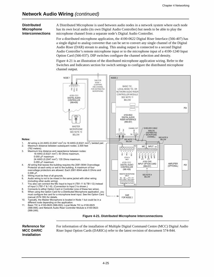
Chapter 4 Networking
Network Audio Wiring (continued)
Distributed Microphone Interconnections
A Distributed Microphone is used between audio nodes in a network system where each node has its own local audio (its own Digital Audio Controller) but needs to be able to play the microphone channel from a separate node’s Digital Audio Controller.
For a distributed microphone application, the 4100-0622 Digital Riser Interface (566-407) has a single digital to analog converter that can be set to convert any single channel of the Digital Audio Riser (DAR) stream to analog. This analog output is connected to a second Digital Audio Controller’s remote microphone input or to the microphone input of a 4100-1240 Input Option Card (566-037). DIP switches configure the channel selection and density.
Figure 4-21 is an illustration of the distributed microphone application wiring. Refer to the Switches and Indicators section for switch settings to configure the distributed microphone channel output.
Figure 4-21. Distributed Microphone Interconnections
Reference for MCC DARIC Installation
For information of the installation of Multiple Digital Command Centre (MCC) Digital Audio Riser Input Option Cards (DARICs) refer to the latest revision of document 574-844.
Notes: 1. All wiring is 24 AWG (0.2047 mm2) to 18 AWG (0.8321 mm2), twisted pair. 2. Maximum distance between subsequent nodes: 2,500 feet
(762 meters). 3. Maximum line distance and capacitance between nodes:
18 AWG (0.8321 mm2): 40 Ohms maximum, 0.055 μF maximum 24 AWG (0.2047 mm2): 135 Ohms maximum, 0.055 μF maximum
4. All wiring that leaves the building requires the 2081-9044 Overvoltage Protector at each entry or exit to the building. A maximum of four overvoltage protectors are allowed. Each 2081-9044 adds 6 Ohms and 0.006 μF.
5. Wiring must be free of all grounds. 6. Audio wiring is not to be mixed in the same jacket with other wiring
(including other audio wiring). 7. You also can connect the Mic Input to Input 4 (TB1-11 & TB1-12) instead
of Input 3 (TB1-7 & 1-8). (Connection to Input 3 is shown.) 8. Connects to either Option Card or Controller (one of these two wires). 9. When using the Option Card for a Distributed Microphone application, you
must configure the card for a microphone level input. See the Option Card manual (579-160) for details.
10. Typically, the Master Microphone is located in Node 1 but could be in a different node depending on the application.
11. Basic TIC is 4100-0620 (566-093); Local Mode TIC is 4100-0625 (566-094); and Network Audio Riser Controller Module is 4100-0623 (566-249).
4-25
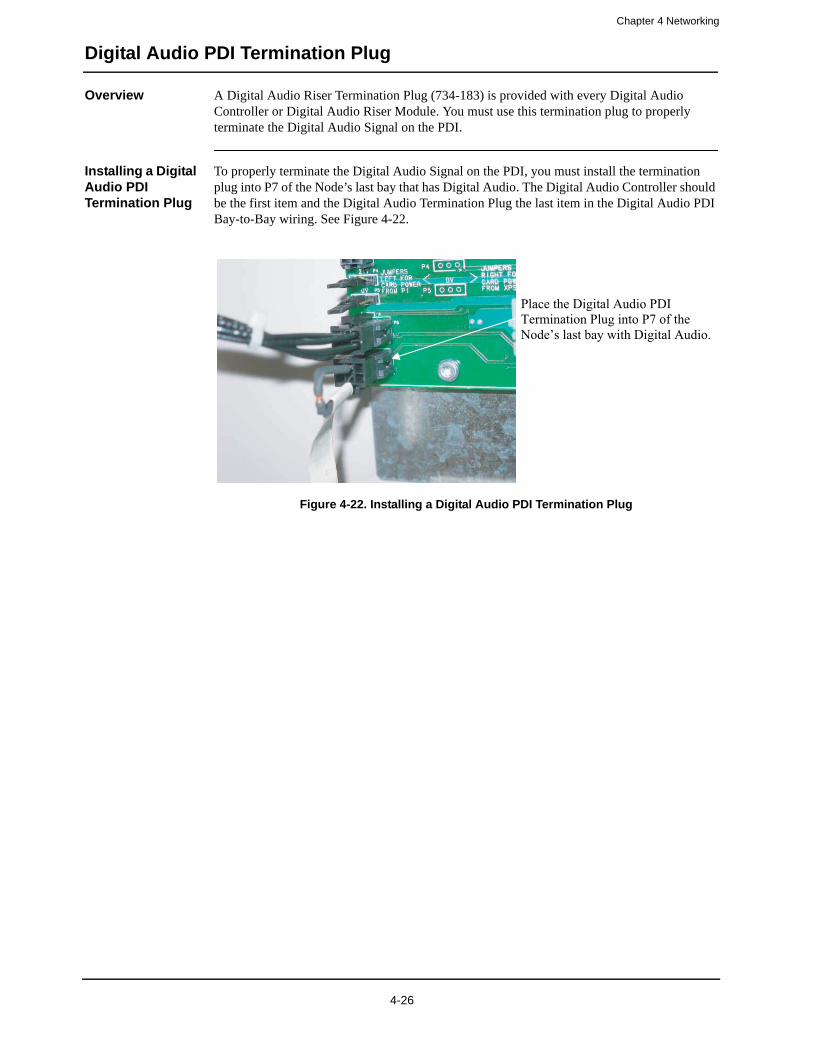
Chapter 4 Networking
Digital Audio PDI Termination Plug
Overview A Digital Audio Riser Termination Plug (734-183) is provided with every Digital Audio Controller or Digital Audio Riser Module. You must use this termination plug to properly terminate the Digital Audio Signal on the PDI.
Installing a Digital Audio PDI Termination Plug
To properly terminate the Digital Audio Signal on the PDI, you must install the termination plug into P7 of the Node’s last bay that has Digital Audio. The Digital Audio Controller should be the first item and the Digital Audio Termination Plug the last item in the Digital Audio PDI Bay-to-Bay wiring. See Figure 4-22.
Figure 4-22. Installing a Digital Audio PDI Termination Plug
Place the Digital Audio PDI Termination Plug into P7 of the Node’s last bay with Digital Audio.
4-26
Chapter 5
The System Power Supply
Introduction This chapter describes how the system power supply (SPS) is installed and configured by the factory. Check the information in this chapter to make sure the SPS is installed correctly.
In this chapter This chapter covers the following topics:
Topic Page
SPS Specifications 5-2
SPS Configuration 5-4
SPS LED Indications 5-5
Troubleshooting 5-6
5-1
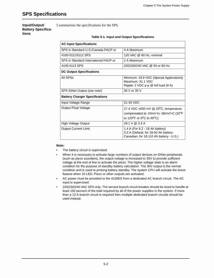
Chapter 5 The System Power Supply
SPS Specifications
Input/Output/Battery Specifica-tions
5 summarizes the specifications for the SPS.
Note:
• The battery circuit is supervised.
• When it is necessary to activate large numbers of output devices on IDNet peripherals (such as piezo sounders), the output voltage is increased to 35V to provide sufficient voltage at the end of line to activate the piezo. The higher voltage state is an alarm condition for the purpose of standby battery calculation. The 30V output is the normal condition and is used to prolong battery standby. The system CPU will activate the boost feature when 10 LED, Piezo or other outputs are activated.
• AC power must be provided to the 4100ES from a dedicated AC branch circuit. The AC input is supervised.
• 220/230/240 VAC SPS only: The service branch circuit breaker should be sized to handle at least 150 percent of the total required by all of the power supplies in the system. If more than a 13 A branch circuit is required then multiple dedicated branch circuits should be used instead.
Table 5-1. Input and Output Specifications
AC Input Specifications
SPS in Standard U.S./Canada FACP or 4 A Maximum
4100-5111/5112 SPS 120 VAC @ 60 Hz, nominal
SPS in Standard International FACP or 2 A Maximum
4100-5113 SPS 220/230/240 VAC @ 50 or 60 Hz
DC Output Specifications
All SPSs Minimum: 19.9 VDC (Special Applications)Maximum: 31.1 VDCRipple: 2 VDC p-p @ full load (9 A)
SPS IDNet Output (see note) 30 V or 35 V
Battery Charger Specifications
Input Voltage Range 21-33 VDC
Output Float Voltage 27.4 VDC ±500 mV @ 20oC, temperature
compensated at -24mV to -36mV/×C (32oF
to 120oF or 0oC to 49oC)
High Voltage Output 29.1 V @ 3.3 A
Output Current Limit 1.4 A (For 6.2 - 18 Ah battery)3.3 A (Default; for 18-50 Ah battery- Canadian; for 18-110 Ah battery - U.S.)
5-2
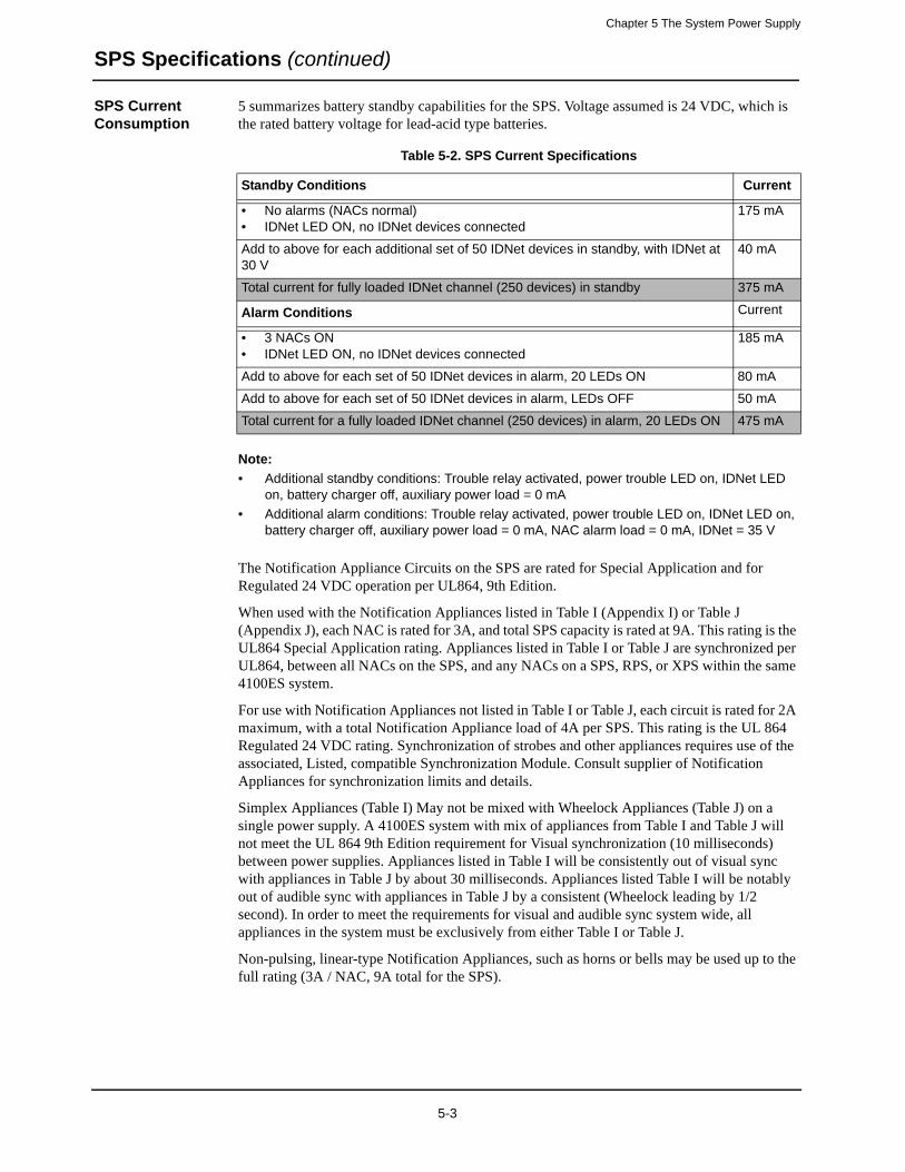
Chapter 5 The System Power Supply
SPS Specifications (continued)
SPS Current Consumption
5 summarizes battery standby capabilities for the SPS. Voltage assumed is 24 VDC, which is the rated battery voltage for lead-acid type batteries.
Note:
• Additional standby conditions: Trouble relay activated, power trouble LED on, IDNet LED on, battery charger off, auxiliary power load = 0 mA
• Additional alarm conditions: Trouble relay activated, power trouble LED on, IDNet LED on, battery charger off, auxiliary power load = 0 mA, NAC alarm load = 0 mA, IDNet = 35 V
The Notification Appliance Circuits on the SPS are rated for Special Application and for Regulated 24 VDC operation per UL864, 9th Edition.
When used with the Notification Appliances listed in Table I (Appendix I) or Table J (Appendix J), each NAC is rated for 3A, and total SPS capacity is rated at 9A. This rating is the UL864 Special Application rating. Appliances listed in Table I or Table J are synchronized per UL864, between all NACs on the SPS, and any NACs on a SPS, RPS, or XPS within the same 4100ES system.
For use with Notification Appliances not listed in Table I or Table J, each circuit is rated for 2A maximum, with a total Notification Appliance load of 4A per SPS. This rating is the UL 864 Regulated 24 VDC rating. Synchronization of strobes and other appliances requires use of the associated, Listed, compatible Synchronization Module. Consult supplier of Notification Appliances for synchronization limits and details.
Simplex Appliances (Table I) May not be mixed with Wheelock Appliances (Table J) on a single power supply. A 4100ES system with mix of appliances from Table I and Table J will not meet the UL 864 9th Edition requirement for Visual synchronization (10 milliseconds) between power supplies. Appliances listed in Table I will be consistently out of visual sync with appliances in Table J by about 30 milliseconds. Appliances listed Table I will be notably out of audible sync with appliances in Table J by a consistent (Wheelock leading by 1/2 second). In order to meet the requirements for visual and audible sync system wide, all appliances in the system must be exclusively from either Table I or Table J.
Non-pulsing, linear-type Notification Appliances, such as horns or bells may be used up to the full rating (3A / NAC, 9A total for the SPS).
Table 5-2. SPS Current Specifications
Standby Conditions Current
• No alarms (NACs normal)• IDNet LED ON, no IDNet devices connected
175 mA
Add to above for each additional set of 50 IDNet devices in standby, with IDNet at 30 V
40 mA
Total current for fully loaded IDNet channel (250 devices) in standby 375 mA
Alarm Conditions Current
• 3 NACs ON• IDNet LED ON, no IDNet devices connected
185 mA
Add to above for each set of 50 IDNet devices in alarm, 20 LEDs ON 80 mA
Add to above for each set of 50 IDNet devices in alarm, LEDs OFF 50 mA
Total current for a fully loaded IDNet channel (250 devices) in alarm, 20 LEDs ON 475 mA
5-3

Chapter 5 The System Power Supply
SPS Configuration
Overview This section contains information about SPS jumpers and DIP switches. Refer to Chapter 4 4 of this document for information on setting the jumpers.
Jumper Settings P1: Earth connect jumper. Note that the P1 location is clearly designated on the PCB silk screen.
• Position 1 – 2: Enables Earth fault monitoring.
• Position 2 – 3: Disables Earth fault monitoring.
Only one power module should be set for earth fault monitoring for each location within a system. Normally, the SPS in the CPU bay is set to monitor for earth faults. If there is a second SPS connected to the same set of batteries, that SPS should have earth fault monitoring disabled. Other power modules that can be set to monitor earth fault conditions are TPS, RPS and XBC. When located under common 0V with a TPS, the TPS should be set to monitor earth faults, and other co-located power modules should be set to disable earth fault monitoring.
P2: If the SPS IDNet outputs are being used, you may change P2 to configure the IDNet shield connection. Note that the P2 pin 1 location is towards P3.
• Position 1 – 2: Connects the shield to 0 V (default).
• Position 2 – 3: Connects the shield to earth ground.
P3: City Card and Relay Card operation. Note that the P3 pin 1 location is towards P2.
• Position 1-2: Install in position 1-2 only if a relay card 4100-6033 is installed and has relay 3 programmed for operation other than "Trouble"
• Position 2-3: (default) For City Card operation and for use with 4100-6033 if relay 3 is programmed for "activate on trouble" operation
Setting the Device Address
Refer to Appendix A to set the device address for the SPS with DIP switch SW1.
5-4

Chapter 5 The System Power Supply
SPS LED Indications
LEDs The SPS has the following LEDs:LED1 (yellow). Illuminates when NAC 1 is ON or in Trouble.LED2 (yellow). Illuminates when NAC 2 is ON or in Trouble.LED3 (yellow). Illuminates when NAC 3 is ON or in Trouble.LED4 (yellow). Illuminates to indicate a communications loss with the system CPU; normally off. If this LED is blinking, try re-loading the software to FLASH.LED5 (yellow). Indicates IDNet status.
• Slow blink: Class A open circuit trouble.
• Fast blink: Short circuit trouble.
• On steady: No devices detected/ channel failure.
• Normally off.
LED6 (yellow). Indicates power supply status.
• Single blink: Positive earth fault.
• Double blink: Negative earth fault.
• Triple blink: Battery trouble.
• Quadruple blink: Charger trouble.
• On steady: Overcurrent fault.
• Normally off.
LED7 (green). Illuminates when the power supply is powered from the AC line. Off when the power supply is de-energized, or when it is using battery backup power.
5-5

Chapter 5 The System Power Supply
Troubleshooting
Overview This section contains explanations of trouble messages that may appear on the 4100ES display when using the SPS. Heading text in the left margin shows the error message, while the paragraph next to it describes the likely cause of the message.
IDNet Power Monitor Trouble
There is no output voltage from the power supply.
Extra Device Appears if one or more extra devices (i.e., devices that have not been configured for the IDNet channel) are one the system. Only one message appears, regardless of the number of extra devices found.
Class A Trouble There is an open on the IDNet channel. A hardware reset is required to reset the trouble.
Earth Fault Search
Comes up during the Earth Fault Search diagnostic function. Once the search is initiated, the front panel display indicates how far along the search process has progressed (10%, 25%… 75%), and then shows the results of the search. The result either identifies the offending circuit or indicates that the earth fault could not be found. SPS circuits (IDNet, NAC, and aux power) are searched. System alarm and trouble processing is suspended during the search.
Short Circuit Appears when a short is detected on the IDNet channel. This status clears automatically when the short circuit is removed.
Channel Fail Appears when each device on the IDNet channel has been configured, and when none of the devices are communicating on the channel. This message does not appear if there are no configured devices on the IDNet channel.
No Answer/Bad Answer
Occurs when the 4100ES is put into a diagnostic mode and finds a device not responding, or responding unreliably. Refer to the ES Panel Programmer’s Manual (574-849) for information on how to perform this diagnostic.
Output Abnormal Occurs when 24 VDC is not present on TrueAlarm devices or when TrueAlarm sensor bases with relay driver outputs are not properly supervised or when isolator devices are in isolation mode.
5-6
Chapter 6
4100ES SPS Field Wiring
Introduction This chapter shows how 4100ES devices are wired to notification appliances. Most of the connections shown herein are reverse-polarity NACs, IDNet circuits, and power circuits.
In this chapter This chapter covers the following topics:
Topic Page
General Field Wiring Guidelines 6-2
Power Supply Wiring Distances 6-5
SPS NAC Field Wiring Guidelines 6-7
SPS NAC Wiring 6-8
SPS IDNet Field Wiring Guidelines 6-10
SPS IDNet Wiring 6-11
SPS Auxiliary Power Wiring 6-13
SPS Auxiliary Relay Wiring 6-15
6-1

Chapter 6 4100ES SPS Field Wiring
General Field Wiring Guidelines
General Guidelines
Make sure these guidelines are accounted for before wiring:
• All wires must be 18 AWG (0.8231 mm2), or as the local code dictates.
• Conductors must test free of all grounds.
• All wiring must be done using copper conductors only, unless noted otherwise.
• If shielded wire is used,
- the metallic continuity of the shield must be maintained throughout the entire cable length.
- the entire length of the cable must have a resistance greater than 1 Megohm to earth ground.
• Underground wiring must be free of all water.
• In areas of high lightning activity, or in areas that have large power surges, the 2081-9027 Transient Suppressor should be used on monitor points.
• Wires must not be run through elevator shafts.
• Wires that run in plenum must be in conduit.
• Splicing is permitted. All spliced connections must either be soldered (resin-core solder), crimped in metal sleeves, or encapsulated with an epoxy resin. When soldering or crimped metal sleeves are used, the junction must be insulated with a high-grade electrical tape that is as sound as the original insulating jacket. Shield continuity must be maintained throughout.
• A system ground must be provided for earth detection and lightning protection devices. This connection must comply with approved earth detection per NFPA780.
• Only system wiring can be run together in the same conduit.
6-2
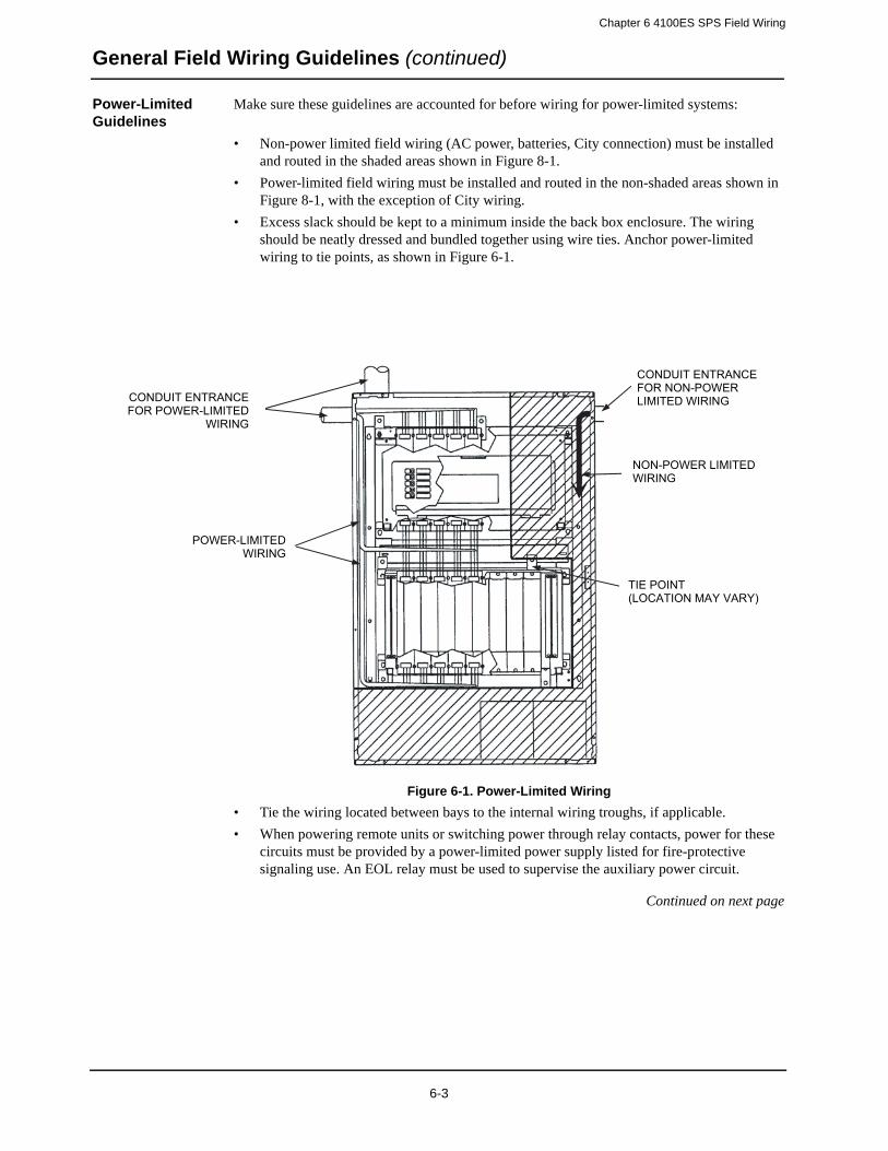
Chapter 6 4100ES SPS Field Wiring
General Field Wiring Guidelines (continued)
Power-Limited Guidelines
Make sure these guidelines are accounted for before wiring for power-limited systems:
• Non-power limited field wiring (AC power, batteries, City connection) must be installed and routed in the shaded areas shown in Figure 8-1.
• Power-limited field wiring must be installed and routed in the non-shaded areas shown in Figure 8-1, with the exception of City wiring.
• Excess slack should be kept to a minimum inside the back box enclosure. The wiring should be neatly dressed and bundled together using wire ties. Anchor power-limited wiring to tie points, as shown in Figure 6-1.
Figure 6-1. Power-Limited Wiring
• Tie the wiring located between bays to the internal wiring troughs, if applicable.
• When powering remote units or switching power through relay contacts, power for these circuits must be provided by a power-limited power supply listed for fire-protective signaling use. An EOL relay must be used to supervise the auxiliary power circuit.
Continued on next page
CONDUIT ENTRANCE FOR POWER-LIMITED
WIRING
POWER-LIMITED WIRING
CONDUIT ENTRANCE FOR NON-POWER LIMITED WIRING
TIE POINT(LOCATION MAY VARY)
NON-POWER LIMITED WIRING
6-3
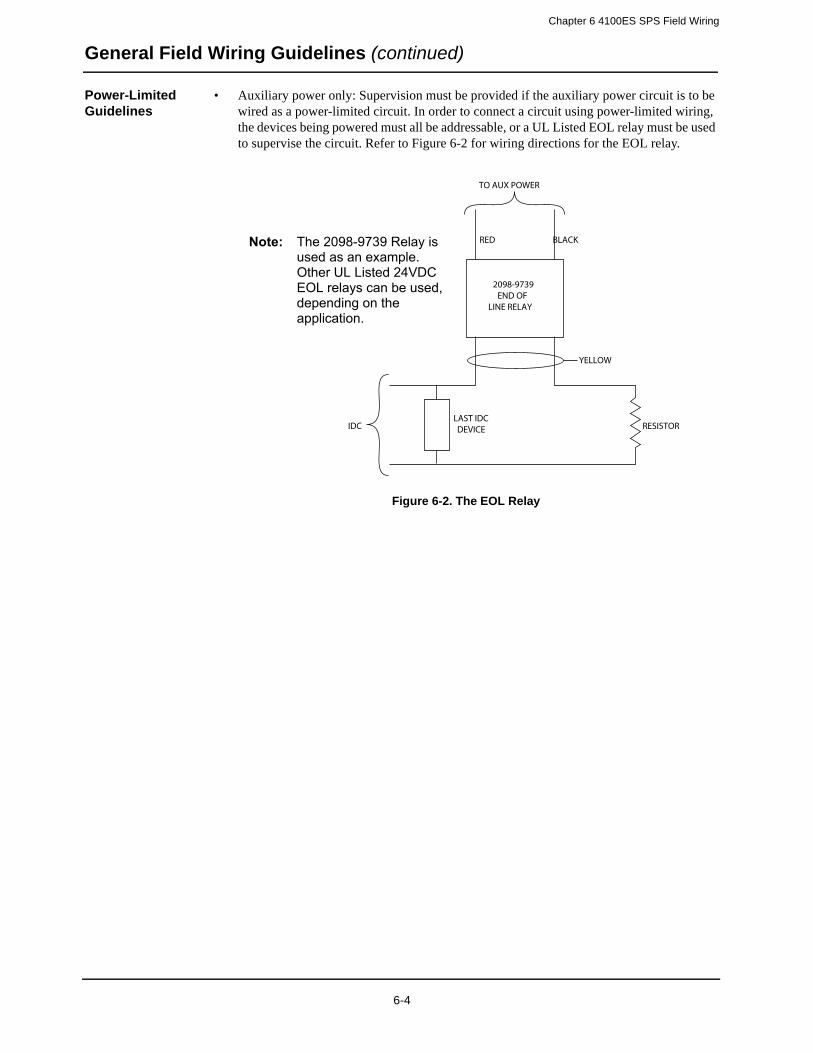
Chapter 6 4100ES SPS Field Wiring
General Field Wiring Guidelines (continued)
Power-Limited Guidelines
• Auxiliary power only: Supervision must be provided if the auxiliary power circuit is to be wired as a power-limited circuit. In order to connect a circuit using power-limited wiring, the devices being powered must all be addressable, or a UL Listed EOL relay must be used to supervise the circuit. Refer to Figure 6-2 for wiring directions for the EOL relay.
Figure 6-2. The EOL Relay
2098-9739END OF
LINE RELAY
TO AUX POWER
RED BLACK
LAST IDCDEVICE
YELLOW
RESISTORIDC
Note: The 2098-9739 Relay is used as an example. Other UL Listed 24VDC EOL relays can be used, depending on the application.
6-4

Chapter 6 4100ES SPS Field Wiring
Power Supply Wiring Distances
Overview Before wiring from any type of power supply to notification appliances, check Tables 8-1 and 8-2 for wiring distances.
Class A NAC Wiring Table
Table 8-1 lists the maximum distances from the NAC terminal block to the last appliance in a Class A configuration, depending on wire gauge and current. Use Table 8-1 to calculate wire distances for your application if you are using Class A wiring.
• Max Distance = distance from SPS/RPS to last appliance.
• This table is calculated at 49 degrees Centigrade (120 degrees Fahrenheit). If you are installing in locations that could be exposed to higher temperatures, refer to NEC Table 8.
• Distances are based on a 3 V drop, and take into account the worst-case panel output voltage.
• If circuit integrity wire is used instead of housing cable in a fire-rated enclosure, reduce wiring distances by 38 feet (12 m) for every 10 feet (3 m) of potential exposure.
Table 6-1. Class A Wiring Distances
Alarm Current @ 24 VDC
Max Distance W./ 18 AWG
(0.8231 mm2)
Max Distance w/ 16 AWG (1.309 mm2)
Max Distance w/ 14 AWG
(2.081 mm2)
Max Distance w/ 12 AWG
(3.309 mm2)
DC Resistanc
e
0.25 A 420 ft. (128 m) 667 ft. (203 m) 1,063 ft. (324 m) 1,691 ft. (515 m) 6 Ohms
0.50 A 210 ft. (64 m) 334 ft. (102 m) 532 ft. (162 m) 845 ft. (258 m) 3 Ohms
0.75 A 140 ft. (43 m) 222 ft. (68 m) 354 ft. (108 m) 564 ft. (172 m) 2 Ohms
1.00 A 105 ft. (32 m) 167 ft. (51 m) 266 ft. (81 m) 423 ft. (129 m) 1.5 Ohms
1.25 A 84 ft. (26 m) 133 ft. (41 m) 213 ft. (65 m) 338 ft. (103 m) 1.2 Ohms
1.50 A 70 ft. (21 m) 111 ft. (34 m) 177 ft. (54 m) 282 ft. (86 m) 1 Ohm
1.75 A 60 ft. (18 m) 95 ft. (29 m) 152 ft. (46 m) 242 ft. (74 m) 0.86 Ohm
2.00 A 53 ft. (16 m) 83 ft. (25 m) 133 ft. (41 m) 211 ft. (64 m) 0.75 Ohm
2.25 A 47 ft. (14 m) 74 ft. (23 m) 118 ft. (36 m) 188 ft. (57 m) 0.67 Ohm
2.50 A 42 ft. (13 m) 67 ft. (20 m) 106 ft. (32 m) 169 ft. (51 m) 0.60 Ohm
2.75 A 38 ft. (12 m) 61 ft. (19 m) 97 ft. (30 m) 154 ft. (47 m) 0.55 Ohm
3.00 A 35 ft. (11 m) 56 ft. (17 m) 89 ft. (27 m) 141 ft. (43 m) 0.50 Ohm
6-5

Chapter 6 4100ES SPS Field Wiring
Power Supply Wiring Distances (continued)
Class B NAC Wiring Table
Table 8-2 lists the maximum distances from the NAC terminal block to the last appliance in a Class B configuration, depending on wire gauge and current. Use Table 8-2 to calculate wire distances for your application if you are using Class B wiring.
Note:
• Max Distance = distance from SPS or RPS to last appliance.
• This table is calculated at 49 degrees Centigrade (120 degrees Fahrenheit). If you are installing in locations that could be exposed to higher temperatures, refer to NEC Table 8.
• Distances are based on a 3 V drop, and take into account the worst-case panel output voltage.
• If circuit integrity wire is used instead of housing cable in a fire rated enclosure, reduce wiring distances by 38 feet (12 m) for every 10 feet (3 m) of potential exposure.
Table 6-2. Class B Wiring Distances
Alarm Current
@ 24 VDC
Max Distance w/ 18 AWG
(0.8231 mm2)
Max Distance w/ 16 AWG
(1.309 mm2)
Max Distance w/ 14 AWG
(2.081 mm2)
Max Distance w/ 12 AWG
(3.309 mm2)
DC Resistance
0.25 A 840 ft. (256 m) 1,335 ft. (407 m)
2,126 ft. (648 m) 3,382 ft. (1,031 m)
12 Ohms
0.50 A 420 ft. (128 m) 667 ft. (203 m) 1,063 ft. (324 m) 1,691 ft. (515 m)
6 Ohms
0.75 A 280 ft. (85 m) 445 ft. (136 m) 709 ft. (216 m) 1,127 ft. (344 m)
4 Ohms
1.00 A 210 ft. (64 m) 334 ft. (102 m) 532 ft. (162 m) 845 ft. (258 m) 3 Ohms
1.25 A 168 ft. (51 m) 267 ft. (81 m) 425 ft. (130 m) 676 ft. (206 m) 2.4 Ohms
1.50 A 140 ft. (43 m) 222 ft. (68 m) 354 ft. (108 m) 564 ft. (172 m) 2 Ohms
1.75 A 120 ft. (37 m) 191 ft. (58 m) 304 ft. (93 m) 483 ft. (147 m) 1.71 Ohms
2.00 A 105 ft. (32 m) 167 ft. (51 m) 266 ft. (81 m) 423 ft. (129 m) 1.5 Ohms
2.25 A 93 ft. (28 m) 148 ft. (45 m) 236 ft. (72 m) 376 ft. (115 m) 1.33 Ohms
2.50 A 84 ft. (26 m) 133 ft. (41 m) 213 ft. (65 m) 338 ft. (103 m) 1.2 Ohms
2.75 A 76 ft. (23 m) 121 ft. (37 m) 193 ft. (59 m) 307 ft. (94 m) 1.09 Ohms
3.00 A 70 ft. (21 m) 111 ft. (34 m) 177 ft. (54 m) 282 ft. (86 m) 1 Ohm
6-6

Chapter 6 4100ES SPS Field Wiring
SPS NAC Field Wiring Guidelines
Guidelines Review the following guidelines for NACs before you begin NAC field wiring.
• All wiring is 18 AWG (0.8231 mm2) (minimum) to 12 AWG (3.309 mm2) (maximum).
• All wiring is supervised and power-limited.
• The maximum alarm current is 3 A per circuit. The supervisory current is 2.03 mA at
• 24 VDC.
• The nominal voltage rating is 24 VDC, 2 V p-p ripple (maximum).
• The total available current from the SPS is 9 A, unless it is used for REGULATED
• 24 VDC notification appliances, where the SPS/RPS is rated for 4Amps notification. Any current used for card power by modules plugged into the PDI, as well as any auxiliary 24 VDC current, must be deducted from the total available current.
• Terminal designations “+” and “-” are for the alarm state.
• Compatible TrueAlert non-addressable appliances for NACs are:
- 4901-series Horn- 4903-series A/V- 4903-series S/V - 4904-series V/O
• A maximum of 70 appliances can be supported per circuit.
6-7
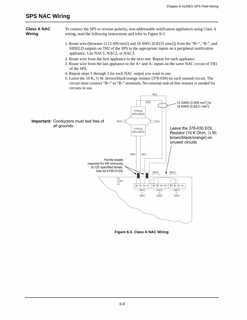
Chapter 6 4100ES SPS Field Wiring
SPS NAC Wiring
Class A NAC Wiring
To connect the SPS to reverse-polarity, non-addressable notification appliances using Class A wiring, read the following instructions and refer to Figure 8-3.
1. Route wire (between 12 [3.309 mm2] and 18 AWG [0.8231 mm2]) from the “B+”, “B-”, and SHIELD outputs on TB2 of the SPS to the appropriate inputs on a peripheral notification appliance. Use NAC1, NAC2, or NAC3.
2. Route wire from the first appliance to the next one. Repeat for each appliance.3. Route wire from the last appliance to the A+ and A- inputs on the same NAC circuit of TB1
of the SPS.4. Repeat steps 1 through 3 for each NAC output you want to use.5. Leave the 10 K, ½ W, brown/black/orange resistor (378-030) on each unused circuit. The
circuit must connect “B+” to “B-” terminals. No external end-of-line resistor is needed for circuits in use.
Figure 6-3. Class A NAC Wiring
P1321
B+ B- A+ A-
TYPICALAPPLIANCE
RED
RED
RED
NAC1
B+ B- A+ A-
NAC1
B+ B- A+ A-
NAC1
LED1 LED2 LED3
TYPICALAPPLIANCE
BLK
BLK
BLK
NAC2 NAC3
12 AWG (3.309 mm2) to 18 AWG (0.8231 mm2)
Important: Conductors must test free of all grounds. Leave the 378-030 EOL
Resistor (10 K Ohm, ½ W; brown/black/orange) on unused circuits
Ferrite beads required for RF immunity
to CE specified levels. Use kit 4100-5129.
6-8
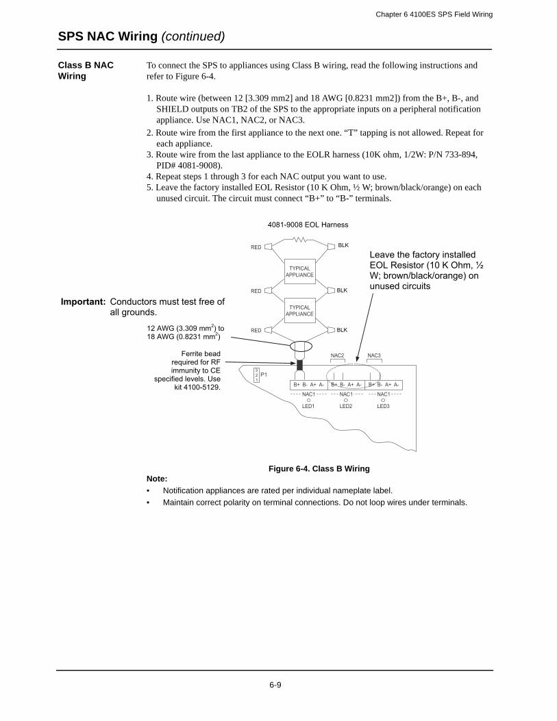
Chapter 6 4100ES SPS Field Wiring
SPS NAC Wiring (continued)
Class B NAC Wiring
To connect the SPS to appliances using Class B wiring, read the following instructions and refer to Figure 6-4.
1. Route wire (between 12 [3.309 mm2] and 18 AWG [0.8231 mm2]) from the B+, B-, and SHIELD outputs on TB2 of the SPS to the appropriate inputs on a peripheral notification appliance. Use NAC1, NAC2, or NAC3.
2. Route wire from the first appliance to the next one. “T” tapping is not allowed. Repeat for each appliance.
3. Route wire from the last appliance to the EOLR harness (10K ohm, 1/2W: P/N 733-894, PID# 4081-9008).
4. Repeat steps 1 through 3 for each NAC output you want to use.5. Leave the factory installed EOL Resistor (10 K Ohm, ½ W; brown/black/orange) on each
unused circuit. The circuit must connect “B+” to “B-” terminals.
Figure 6-4. Class B WiringNote:
• Notification appliances are rated per individual nameplate label.
• Maintain correct polarity on terminal connections. Do not loop wires under terminals.
P1321
B+ B- A+ A-
TYPICALAPPLIANCE
RED BLK
NAC1
B+ B- A+ A-
NAC1
B+ B- A+ A-
NAC1
LED1 LED2 LED3
TYPICALAPPLIANCE
10K 1/2W (133-894)
NAC2 NAC3
RED RED
RED RED
Important: Conductors must test free of all grounds.
12 AWG (3.309 mm2) to 18 AWG (0.8231 mm2)
BLK
BLK
BLK
4081-9008 EOL Harness
Leave the factory installed EOL Resistor (10 K Ohm, ½ W; brown/black/orange) on unused circuits
Ferrite bead required for RF immunity to CE
specified levels. Use kit 4100-5129.
6-9

Chapter 6 4100ES SPS Field Wiring
SPS IDNet Field Wiring Guidelines
IDNet Wiring Up to 250 IDNet initiating devices are supported on the SPS IDNet channel. The SPS supports both Class A and Class B wiring.
Class A wiring allows IDNet appliances to communicate with the SPS even in the event of a single open circuit somewhere in the loop. Class A wiring requires that two wires are routed from the SPS to each IDNet appliance, and then back again to the SPS.
Class B wiring allows “T” tapping, and therefore requires less wiring distance per installation than Class A. Additionally, Class B wiring does not require end-of-line resistors, because each IDNet appliance communicates directly to the SPS.
Guidelines Make sure these guidelines are accounted for before installing the cards.
• For Style 4 operation:
- The maximum distance to any device is 2500 feet (762 m) for 126-250 devices, or 4000 feet (1220 m) if 125 or fewer devices are used.
- “T” taps are allowed.- The maximum total wire allowed is 10,000 feet, or 0.58uF.- Maximum allowed line-to-line capacitance (“+” to “-” terminals) is 0.58 uF. For appli-
cations with shielded wire, be sure that the total capacitance from line to line plus the shield to either line is no more than 0.58 uF.
• For Style 6 operation, the maximum loop distance is 2,500 feet (762 m). “T” taps are not allowed.
• Use supplied ferrite beads with the SPS. Loop wires once through the supplied ferrite bead(s) as shown in Figure 6-5.
Figure 6-5. Loop Wiring as Shown
6-10
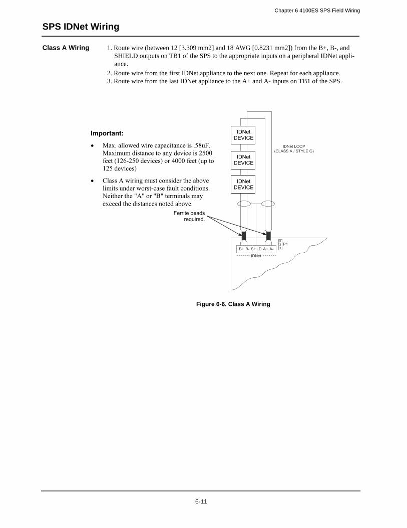
Chapter 6 4100ES SPS Field Wiring
SPS IDNet Wiring
Class A Wiring 1. Route wire (between 12 [3.309 mm2] and 18 AWG [0.8231 mm2]) from the B+, B-, and SHIELD outputs on TB1 of the SPS to the appropriate inputs on a peripheral IDNet appli-ance.
2. Route wire from the first IDNet appliance to the next one. Repeat for each appliance.3. Route wire from the last IDNet appliance to the A+ and A- inputs on TB1 of the SPS.
Figure 6-6. Class A Wiring
B+ B- SHLD
IDNet
A+P1
321A-
IDNetDEVICE
IDNetDEVICE
IDNetDEVICE
IDNet LOOP(CLASS A / STYLE G)
Important:
• Max. allowed wire capacitance is .58uF. Maximum distance to any device is 2500 feet (126-250 devices) or 4000 feet (up to 125 devices)
• Class A wiring must consider the above limits under worst-case fault conditions. Neither the "A" or "B" terminals may exceed the distances noted above.
IDNetDEVICE
IDNetDEVICE
IDNetDEVICE
Ferrite beads required.
6-11
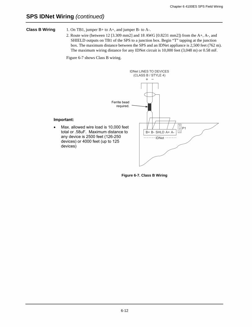
Chapter 6 4100ES SPS Field Wiring
SPS IDNet Wiring (continued)
Class B Wiring 1. On TB1, jumper B+ to A+, and jumper B- to A-.
2. Route wire (between 12 [3.309 mm2] and 18 AWG [0.8231 mm2]) from the A+, A-, and SHIELD outputs on TB1 of the SPS to a junction box. Begin “T” tapping at the junction box. The maximum distance between the SPS and an IDNet appliance is 2,500 feet (762 m). The maximum wiring distance for any IDNet circuit is 10,000 feet (3,048 m) or 0.58 mF.
Figure 6-7 shows Class B wiring.
Figure 6-7. Class B Wiring
B+ B- SHLD
IDNet
A+P1
321A-
IDNet LINES TO DEVICES(CLASS B / STYLE 4)
Important:
• Max. allowed wire load is 10,000 feet total or .58uF. Maximum distance to any device is 2500 feet (126-250 devices) or 4000 feet (up to 125 devices)
Ferrite bead required.
6-12
Chapter 6 4100ES SPS Field Wiring
SPS Auxiliary Power Wiring
Guidelines • All wiring is 18 AWG (0.8231 mm2) and 12 AWG (3.309 mm2).
• All wiring is power-limited.
• When a NAC is configured as an auxiliary power circuit, no end-of-line resistor is used.
• Auxiliary power may be taken from the dedicated auxiliary power tap or from an unused NAC.
• If auxiliary power is taken from NAC terminals, the NAC must be configured as an auxiliary power point type in the 4100 Programmer.
• Remove end-of-line resistors from NACs when used for auxiliary power.
• External wiring from the dedicated auxiliary power tap is not supervised unless an end-of-line relay is wired coil to auxiliary power, and Normally Open contacts are monitored by a system power point. Relay current must be considered as part of the load. When NACs are used as aux. power taps, they are supervised for overcurrent or short-circuit faults.
• All wiring that leaves the building requires overvoltage protection. Install module 2081-9044 wherever wire enters or exits the building. A maximum of four 2081-9044 Modules may be connected to one channel.
• Voltage rating: 24 VDC (nominal), 2 V P-P ripple (maximum).
• The following devices are compatible with 24VDC aux. power:
- 2088-series relays and door holders- 2098-series four-wire smoke detectors- 2190-series monitor and signal ZAMs- 4090-series IDNet ZAMs- 4098-series four-wire smoke detectors and duct detectors- 2190-9039 Printer- 4190-9050/9051 4-20 mA ZAMs- 4603-9101 LCD Annunciator
• The total auxiliary current available is 5 A. The total current available for the entire SPS is 9A (special application) or 4A regulated 24VDC, including NAC, auxiliary, and card power.
6-13
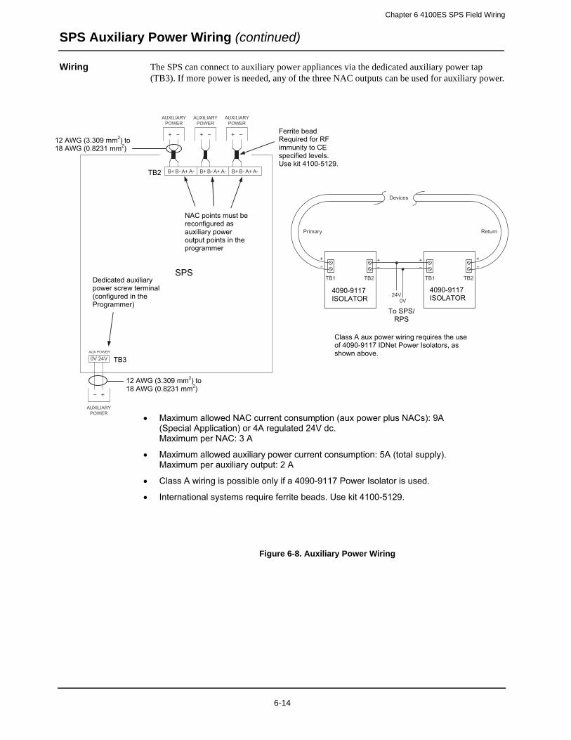
Chapter 6 4100ES SPS Field Wiring
SPS Auxiliary Power Wiring (continued)
Wiring The SPS can connect to auxiliary power appliances via the dedicated auxiliary power tap (TB3). If more power is needed, any of the three NAC outputs can be used for auxiliary power.
Figure 6-8. Auxiliary Power Wiring
B+
0V 24VAUX POWER
B- A+ A- B+ B- A+ A- B+ B- A+ A-
AUXILIARYPOWER
AUXILIARYPOWER
AUXILIARYPOWER
AUXILIARYPOWER
• Maximum allowed NAC current consumption (aux power plus NACs): 9A (Special Application) or 4A regulated 24V dc. Maximum per NAC: 3 A
• Maximum allowed auxiliary power current consumption: 5A (total supply). Maximum per auxiliary output: 2 A
• Class A wiring is possible only if a 4090-9117 Power Isolator is used.
• International systems require ferrite beads. Use kit 4100-5129.
Devices
Primary Return
TB1 TB2
24V0V
TB1 TB2
To SPS/ RPS
Class A aux power wiring requires the use of 4090-9117 IDNet Power Isolators, as shown above.
4090-9117 ISOLATOR
4090-9117 ISOLATOR
SPS
TB2
TB3
Dedicated auxiliary power screw terminal (configured in the Programmer)
NAC points must be reconfigured as auxiliary power output points in the programmer
12 AWG (3.309 mm2) to 18 AWG (0.8231 mm2)
12 AWG (3.309 mm2) to 18 AWG (0.8231 mm2)
Ferrite bead Required for RF immunity to CE specified levels. Use kit 4100-5129.
6-14
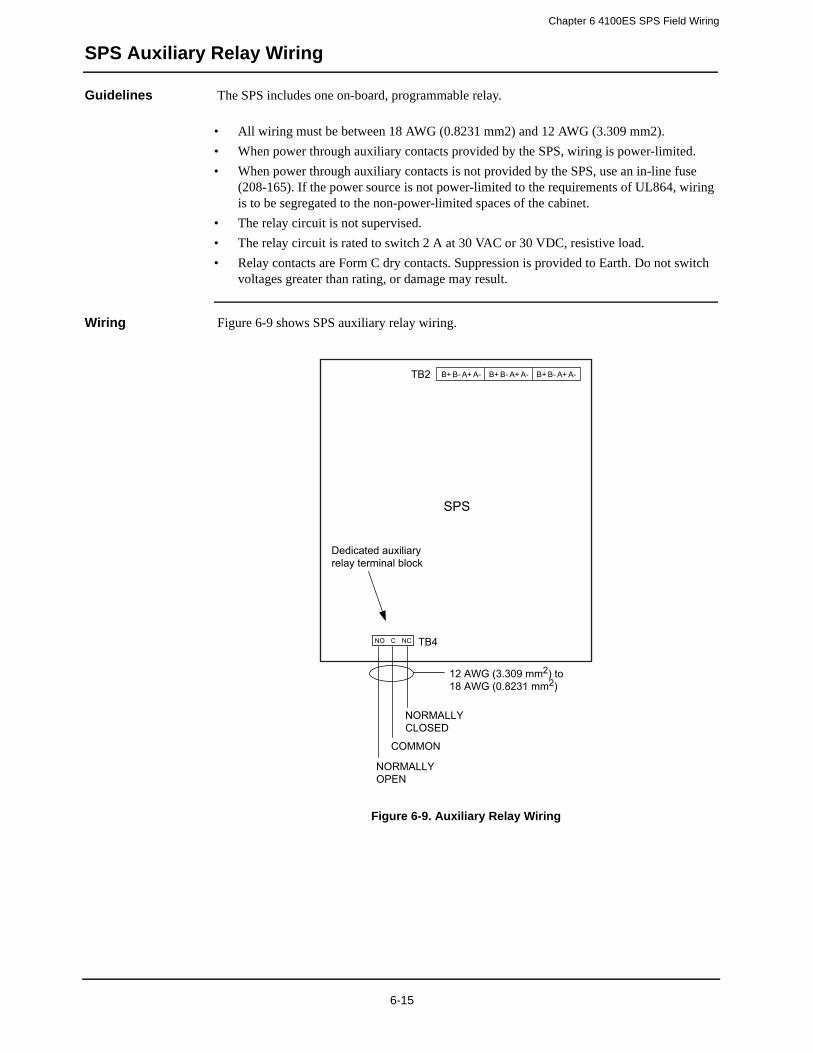
Chapter 6 4100ES SPS Field Wiring
SPS Auxiliary Relay Wiring
Guidelines The SPS includes one on-board, programmable relay.
• All wiring must be between 18 AWG (0.8231 mm2) and 12 AWG (3.309 mm2).
• When power through auxiliary contacts provided by the SPS, wiring is power-limited.
• When power through auxiliary contacts is not provided by the SPS, use an in-line fuse (208-165). If the power source is not power-limited to the requirements of UL864, wiring is to be segregated to the non-power-limited spaces of the cabinet.
• The relay circuit is not supervised.
• The relay circuit is rated to switch 2 A at 30 VAC or 30 VDC, resistive load.
• Relay contacts are Form C dry contacts. Suppression is provided to Earth. Do not switch voltages greater than rating, or damage may result.
Wiring Figure 6-9 shows SPS auxiliary relay wiring.
Figure 6-9. Auxiliary Relay Wiring
B+ B- A+ A- B+ B- A+ A- B+ B- A+ A-
SPS
TB2
TB4
12 AWG (3.309 mm2) to18 AWG (0.8231 mm2)
Dedicated auxiliaryrelay terminal block
NORMALLYCLOSED
COMMON
NORMALLYOPEN
NO C NC
6-15


Chapter 7
PC Software Connections
Introduction The service port on the CPU daughter card allows the 4100ES panel to connect to a PC’s running important utilities, such as diagnostics, programming, CPU firmware downloading, and channel monitoring.
The panel can also connect to a remote PC through the 4100-9832 Service Modem or through the Ethernet.
In this chapter This chapter covers the following topics:
Topic Page
Software Modes 7-2
Ethernet Service Port and Serial Service Port 7-4
7-1
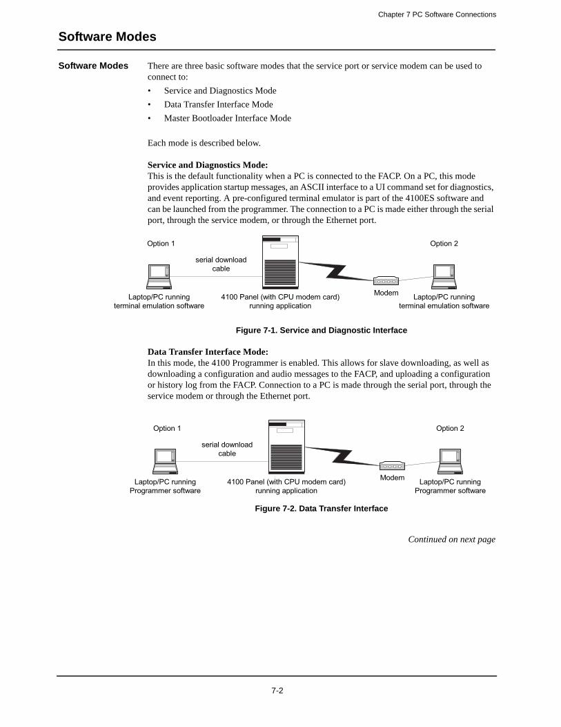
Chapter 7 PC Software Connections
Software Modes
Software Modes There are three basic software modes that the service port or service modem can be used to connect to:
• Service and Diagnostics Mode
• Data Transfer Interface Mode
• Master Bootloader Interface Mode
Each mode is described below.
Service and Diagnostics Mode:This is the default functionality when a PC is connected to the FACP. On a PC, this mode provides application startup messages, an ASCII interface to a UI command set for diagnostics, and event reporting. A pre-configured terminal emulator is part of the 4100ES software and can be launched from the programmer. The connection to a PC is made either through the serial port, through the service modem, or through the Ethernet port.
Figure 7-1. Service and Diagnostic Interface
Data Transfer Interface Mode:In this mode, the 4100 Programmer is enabled. This allows for slave downloading, as well as downloading a configuration and audio messages to the FACP, and uploading a configuration or history log from the FACP. Connection to a PC is made through the serial port, through the service modem or through the Ethernet port.
Figure 7-2. Data Transfer Interface
Continued on next page
Laptop/PC runningterminal emulation software
4100 Panel (with CPU modem card)running application
serial downloadcable
Modem Laptop/PC runningterminal emulation software
Option 1 Option 2
Laptop/PC runningProgrammer software
4100 Panel (with CPU modem card)running application
serial downloadcable
Modem Laptop/PC runningProgrammer software
Option 1 Option 2
7-2
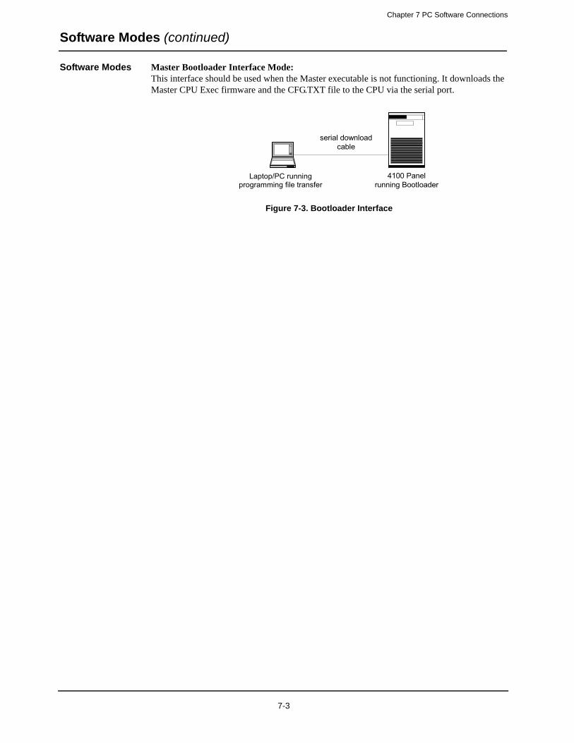
Chapter 7 PC Software Connections
Software Modes (continued)
Software Modes Master Bootloader Interface Mode:This interface should be used when the Master executable is not functioning. It downloads the Master CPU Exec firmware and the CFG.TXT file to the CPU via the serial port.
Figure 7-3. Bootloader Interface
Laptop/PC runningterminal emulation software
4100 Panelrunning Bootloader
serial downloadcable
Laptop/PC running programming file transfer
7-3
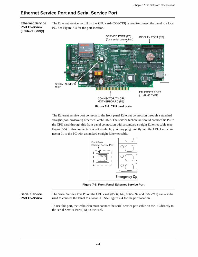
Chapter 7 PC Software Connections
Ethernet Service Port and Serial Service Port
Ethernet Service Port Overview (0566-719 only)
The Ethernet service port J1 on the CPU card (0566-719) is used to connect the panel to a local
PC. See Figure 7-4 for the port location.
Figure 7-4. CPU card ports
The Ethernet service port connects to the front panel Ethernet connection through a standard
straight (non-crossover) Ethernet Patch Cable. The service technician should connect his PC to
the CPU card through this front panel connection with a standard straight Ethernet cable (see
Figure 7-5). If this connection is not available, you may plug directly into the CPU Card con-
nector J1 to the PC with a standard straight Ethernet cable.
Figure 7-5. Front Panel Ethernet Service Port
Serial Service Port Overview
The Serial Service Port P5 on the CPU card (0566, 149, 0566-692 and 0566-719) can also be used to connect the Panel to a local PC. See Figure 7-4 for the port location.
To use this port, the technician must connect the serial service port cable on the PC directly to the serial Service Port (P5) on the card.
SERVICE PORT (P5)(for a serial connection)
DISPLAY PORT (P6)
CONNECTOR TO CPU MOTHERBOARD (P9)
ETHERNET PORT(J1) RJ45 TYPE
SERIAL NUMBERCHIP
Emergency Op
Front PanelEthernet Service Port
7-4
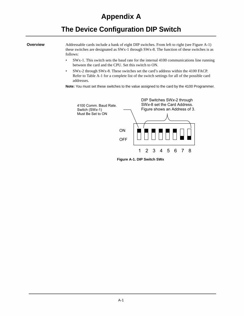
Appendix A
The Device Configuration DIP Switch
Overview Addressable cards include a bank of eight DIP switches. From left to right (see Figure A-1) these switches are designated as SWx-1 through SWx-8. The function of these switches is as follows:
• SWx-1. This switch sets the baud rate for the internal 4100 communications line running between the card and the CPU. Set this switch to ON.
• SWx-2 through SWx-8. These switches set the card’s address within the 4100 FACP. Refer to Table A-1 for a complete list of the switch settings for all of the possible card addresses.
Note: You must set these switches to the value assigned to the card by the 4100 Programmer.
Figure A-1. DIP Switch SWx
A-1

Appendix A The Device Configuration DIP Switch
Ad 1-8 FF NFF NFF NFF NFF NFF NFF NFF NFF NFF NFF NFF NFF NFF NFF NFF NFF NFF NFF NFF NFF NFF NFF NFF NFF NFF NFF NFF NFF NFF
The Service Port
OverviewTable A-1. Card Addresses
dress SW 1-2 SW 1-3 SW 1-4 SW 1-5 SW 1-6 SW 1-7 SW 1-8 Address SW 1-2 SW 1-3 SW 1-4 SW 1-5 SW 1-6 SW 1-7 SW1 ON ON ON ON ON ON OFF 61 ON OFF OFF OFF OFF ON O2 ON ON ON ON ON OFF ON 62 ON OFF OFF OFF OFF OFF O3 ON ON ON ON ON OFF OFF 63 ON OFF OFF OFF OFF OFF O4 ON ON ON ON OFF ON ON 64 OFF ON ON ON ON ON O5 ON ON ON ON OFF ON OFF 65 OFF ON ON ON ON ON O6 ON ON ON ON OFF OFF ON 66 OFF ON ON ON ON OFF O7 ON ON ON ON OFF OFF OFF 67 OFF ON ON ON ON OFF O8 ON ON ON OFF ON ON ON 68 OFF ON ON ON OFF ON O9 ON ON ON OFF ON ON OFF 69 OFF ON ON ON OFF ON O
10 ON ON ON OFF ON OFF ON 70 OFF ON ON ON OFF OFF O11 ON ON ON OFF ON OFF OFF 71 OFF ON ON ON OFF OFF O12 ON ON ON OFF OFF ON ON 72 OFF ON ON OFF ON ON O13 ON ON ON OFF OFF ON OFF 73 OFF ON ON OFF ON ON O14 ON ON ON OFF OFF OFF ON 74 OFF ON ON OFF ON OFF O15 ON ON ON OFF OFF OFF OFF 75 OFF ON ON OFF ON OFF O16 ON ON OFF ON ON ON ON 76 OFF ON ON OFF OFF ON O17 ON ON OFF ON ON ON OFF 77 OFF ON ON OFF OFF ON O18 ON ON OFF ON ON OFF ON 78 OFF ON ON OFF OFF OFF O19 ON ON OFF ON ON OFF OFF 79 OFF ON ON OFF OFF OFF O20 ON ON OFF ON OFF ON ON 80 OFF ON OFF ON ON ON O21 ON ON OFF ON OFF ON OFF 81 OFF ON OFF ON ON ON O22 ON ON OFF ON OFF OFF ON 82 OFF ON OFF ON ON OFF O23 ON ON OFF ON OFF OFF OFF 83 OFF ON OFF ON ON OFF O24 ON ON OFF OFF ON ON ON 84 OFF ON OFF ON OFF ON O25 ON ON OFF OFF ON ON OFF 85 OFF ON OFF ON OFF ON O26 ON ON OFF OFF ON OFF ON 86 OFF ON OFF ON OFF OFF O27 ON ON OFF OFF ON OFF OFF 87 OFF ON OFF ON OFF OFF O28 ON ON OFF OFF OFF ON ON 88 OFF ON OFF OFF ON ON O29 ON ON OFF OFF OFF ON OFF 89 OFF ON OFF OFF ON ON O30 ON ON OFF OFF OFF OFF ON 90 OFF ON OFF OFF ON OFF O31 ON ON OFF OFF OFF OFF OFF 91 OFF ON OFF OFF ON OFF O32 ON OFF ON ON ON ON ON 92 OFF ON OFF OFF OFF ON O33 ON OFF ON ON ON ON OFF 93 OFF ON OFF OFF OFF ON O34 ON OFF ON ON ON OFF ON 94 OFF ON OFF OFF OFF OFF O35 ON OFF ON ON ON OFF OFF 95 OFF ON OFF OFF OFF OFF O36 ON OFF ON ON OFF ON ON 96 OFF OFF ON ON ON ON O37 ON OFF ON ON OFF ON OFF 97 OFF OFF ON ON ON ON O38 ON OFF ON ON OFF OFF ON 98 OFF OFF ON ON ON OFF O39 ON OFF ON ON OFF OFF OFF 99 OFF OFF ON ON ON OFF O40 ON OFF ON OFF ON ON ON 100 OFF OFF ON ON OFF ON O41 ON OFF ON OFF ON ON OFF 101 OFF OFF ON ON OFF ON O42 ON OFF ON OFF ON OFF ON 102 OFF OFF ON ON OFF OFF O43 ON OFF ON OFF ON OFF OFF 103 OFF OFF ON ON OFF OFF O44 ON OFF ON OFF OFF ON ON 104 OFF OFF ON OFF ON ON O45 ON OFF ON OFF OFF ON OFF 105 OFF OFF ON OFF ON ON O46 ON OFF ON OFF OFF OFF ON 106 OFF OFF ON OFF ON OFF O47 ON OFF ON OFF OFF OFF OFF 107 OFF OFF ON OFF ON OFF O48 ON OFF OFF ON ON ON ON 108 OFF OFF ON OFF OFF ON O49 ON OFF OFF ON ON ON OFF 109 OFF OFF ON OFF OFF ON O50 ON OFF OFF ON ON OFF ON 110 OFF OFF ON OFF OFF OFF O51 ON OFF OFF ON ON OFF OFF 111 OFF OFF ON OFF OFF OFF O52 ON OFF OFF ON OFF ON ON 112 OFF OFF OFF ON ON ON O53 ON OFF OFF ON OFF ON OFF 113 OFF OFF OFF ON ON ON O54 ON OFF OFF ON OFF OFF ON 114 OFF OFF OFF ON ON OFF O55 ON OFF OFF ON OFF OFF OFF 115 OFF OFF OFF ON ON OFF O56 ON OFF OFF OFF ON ON ON 116 OFF OFF OFF ON OFF ON O57 ON OFF OFF OFF ON ON OFF 117 OFF OFF OFF ON OFF ON O58 ON OFF OFF OFF ON OFF ON 118 OFF OFF OFF ON OFF OFF O59 ON OFF OFF OFF ON OFF OFF 119 OFF OFF OFF ON OFF OFF O60 ON OFF OFF OFF OFF ON ON
A-2

Appendix BInstalling 4100 FACP Components (Non-4100ES/4100U)
Introduction 4100 back boxes are available in one-, two-, and three-bay sizes. Each can be equipped with a solid or glass door. This chapter describes how to mount all types of non-4100ES/4100U back boxes to a wall, and how to mount system electronics bays into the boxes.
This chapter describes every installation procedure that applies directly to the FACP as well as each step of the host panel installation.
Before beginning the installation, review the next few pages to get a sense of the types of bays and modules that make up the FACP.
In this chapter This chapter covers the following topics:
Topic Page
Introduction to FACPs B-2
Step 1. Mounting Back Boxes B-8
Step 2. Mounting Electronics Bays to Back Boxes B-10
Step 3. Configuring Modules B-14
Step 4. Interconnecting Master Controller Bay Cards B-17
Step 5. Installing Motherboards into Expansion Bays B-18
B-1
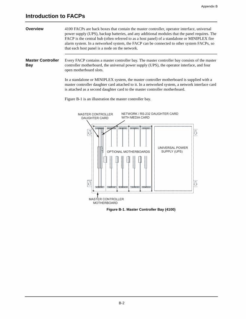
Appendix B
Introduction to FACPs
Overview 4100 FACPs are back boxes that contain the master controller, operator interface, universal power supply (UPS), backup batteries, and any additional modules that the panel requires. The FACP is the central hub (often referred to as a host panel) of a standalone or MINIPLEX fire alarm system. In a networked system, the FACP can be connected to other system FACPs, so that each host panel is a node on the network.
Master Controller Bay
Every FACP contains a master controller bay. The master controller bay consists of the master controller motherboard, the universal power supply (UPS), the operator interface, and four open motherboard slots.
In a standalone or MINIPLEX system, the master controller motherboard is supplied with a master controller daughter card attached to it. In a networked system, a network interface card is attached as a second daughter card to the master controller motherboard.
Figure B-1 is an illustration the master controller bay.
Figure B-1. Master Controller Bay (4100)
MASTER CONTROLLER MOTHERBOARD
MASTER CONTROLLER DAUGHTER CARD
NETWORK / RS-232 DAUGHTER CARDWITH MEDIA CARD
UNIVERSAL POWER SUPPLY (UPS)OPTIONAL MOTHERBOARDS
B-2
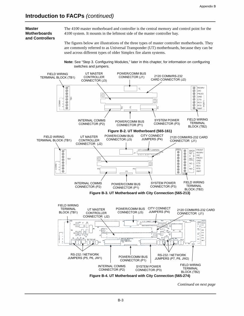
Appendix B
Introduction to FACPs (continued)
Master Motherboards and Controllers
The 4100 master motherboard and controller is the central memory and control point for the 4100 system. It mounts in the leftmost side of the master controller bay.
The figures below are illustrations of the three types of master controller motherboards. They are commonly referred to as Universal Transponder (UT) motherboards, because they can be used across different types of older Simplex fire alarm systems.
Note: See “Step 3. Configuring Modules,” later in this chapter, for information on configuring switches and jumpers.
Figure B-2. UT Motherboard (565-161)
Figure B-3. UT Motherboard with City Connection (565-213)
Figure B-4. UT Motherboard with City Connection (565-274)
Continued on next page
MM
OC
1BT1
1
1J
2P
1P
RESRV24CPIEZOGNDCTSRCV
1TR
OPRTSXMIT
3P
POWER/COMM BUS CONNECTOR (J1) 2120 COMM/RS-232
CARD CONNECTOR (J2)
SYSTEM POWER CONNECTOR (P3)
INTERNAL COMMS CONNECTOR (P2)
UT MASTER CONTROLLER
CONNECTOR (J3)
POWER/COMM BUS CONNECTOR (P1)
FIELD WIRING TERMINAL BLOCK (TB1)
FIELD WIRING TERMINAL
BLOCK (TB2)
MM
OC
TB1
P5
1
J1 P4
GND4
GND3CITY CONNECT JUMPERS
P2P1
RESRVFRONT
24CPIEZO
NCBACK
CNO
NC+NO-
GNDCTSRCVRTSXMIT
P3P6 JW1 JW1 P8
P7
TBL
CITY
POWER/COMM BUS CONNECTOR (J3)
2120 COMM/RS-232 CARD CONNECTOR (J1)
SYSTEM POWER CONNECTOR (P3)
INTERNAL COMMS CONNECTOR (P2)
UT MASTER CONTROLLER
CONNECTOR (J2)
POWER/COMM BUS CONNECTOR (P1)
FIELD WIRING TERMINAL BLOCK (TB1)
FIELD WIRING TERMINAL
BLOCK (TB2)
CITY CONNECT JUMPERS (P4)
JW2
POWER/COMM BUS CONNECTOR (J3)
2120 COMM/RS-232 CARD CONNECTOR (J1)
SYSTEM POWER CONNECTOR (P3)
INTERNAL COMMS CONNECTOR (P2)
UT MASTER CONTROLLER
CONNECTOR (J2)
POWER/COMM BUS CONNECTOR (P1)
FIELD WIRING TERMINAL
BLOCK (TB1)
FIELD WIRING TERMINAL
BLOCK (TB2)
CITY CONNECT JUMPERS (P4)
RS-232 / NETWORK JUMPERS (P5, P6, JW1)
RS-232 / NETWORK JUMPERS (P7, P8, JW2)
)U0
014-
noN (
B-3

Appendix B
Introduction to FACPs (continued)
Master Motherboards and Controllers
The figures below are illustrations of the two UT master controllers.
Note: See “Step 3. Configuring Modules,” later in this chapter, for information on configuring switches and jumpers.
Figure B-5. UT Master Controller (565-333)
Figure B-6. UT Master Controller (565-148)
LED1
P6
P7
P5P3
P2
P1MODEM
UT MASTERCONTROLLER
565-333 H
P4
SW1
1 2
PROGRAMMER PORT (P1)
MODEM JUMPER (P2)
BATTERY BACKUP JUMPER (P3)
FLASH EPROM JUMPER (P5)
EDGE CONNECTOR TO 565-161 MOTHERBOARD (P4)
SYSTEM TROUBLE LED (LED1)
MASTER DISPLAY PORT (P6)
RESET BUTTON (SW1)
Not used (P8)
MASTER DISPLAY JUMPER (P7)
LED1
P6
P7
P5P3
P2
P1MODEM
UT MASTERCONTROLLER
565-333 H
P4
SW1
1 2
PROGRAMMER PORT (P1)
BATTERY BACKUP JUMPER (P2)
FLASH EPROM JUMPER (P3)
EDGE CONNECTOR TO 565-161 MOTHERBOARD (P5, P6))
SYSTEM TROUBLE LED (LED1)
MASTER DISPLAY PORT (P4)
RESET BUTTON (SW1)
B-4
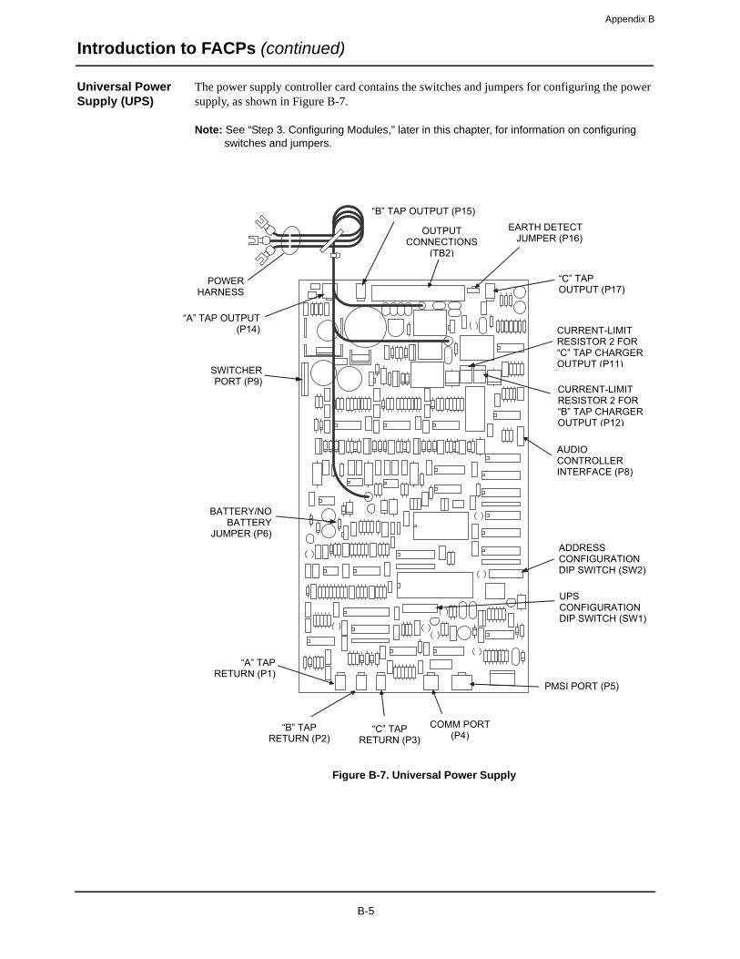
Appendix B
Introduction to FACPs (continued)
Universal Power Supply (UPS)
The power supply controller card contains the switches and jumpers for configuring the power supply, as shown in Figure B-7.
Note: See “Step 3. Configuring Modules,” later in this chapter, for information on configuring switches and jumpers.
Figure B-7. Universal Power Supply
“B” TAP OUTPUT (P15)
“C” TAP OUTPUT (P17)
AUDIO CONTROLLER INTERFACE (P8)
COMM PORT (P4)
“A” TAP RETURN (P1)
“B” TAP RETURN (P2)
“C” TAP RETURN (P3)
CURRENT-LIMIT RESISTOR 2 FOR “C” TAP CHARGER OUTPUT (P11)
ADDRESSCONFIGURATION DIP SWITCH (SW2)
UPSCONFIGURATION DIP SWITCH (SW1)
PMSI PORT (P5)
BATTERY/NO BATTERY
JUMPER (P6)
SWITCHERPORT (P9)
“A” TAP OUTPUT (P14)
POWERHARNESS
OUTPUT CONNECTIONS
(TB2)
EARTH DETECT JUMPER (P16)
CURRENT-LIMIT RESISTOR 2 FOR “B” TAP CHARGER OUTPUT (P12)
B-5
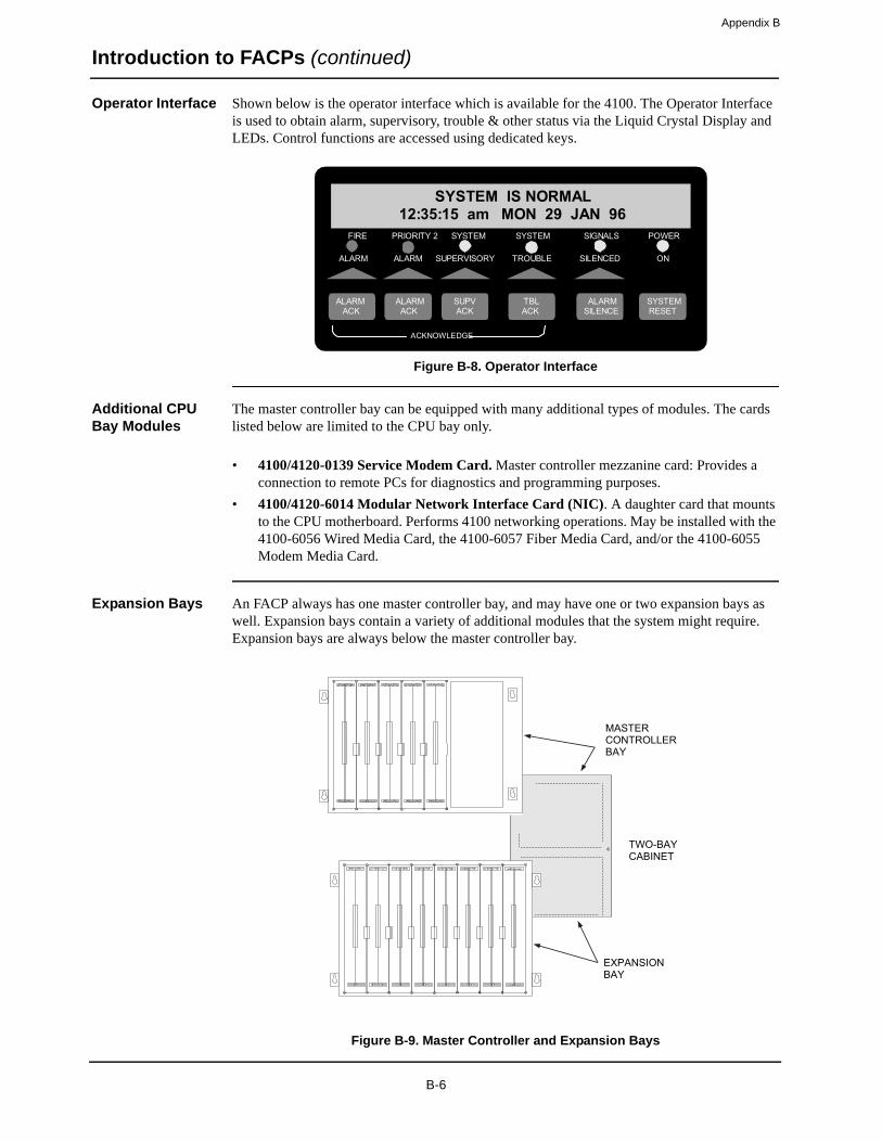
Appendix B
Introduction to FACPs (continued)
Operator Interface Shown below is the operator interface which is available for the 4100. The Operator Interface is used to obtain alarm, supervisory, trouble & other status via the Liquid Crystal Display and LEDs. Control functions are accessed using dedicated keys.
Figure B-8. Operator Interface
Additional CPU Bay Modules
The master controller bay can be equipped with many additional types of modules. The cards listed below are limited to the CPU bay only.
• 4100/4120-0139 Service Modem Card. Master controller mezzanine card: Provides a connection to remote PCs for diagnostics and programming purposes.
• 4100/4120-6014 Modular Network Interface Card (NIC). A daughter card that mounts to the CPU motherboard. Performs 4100 networking operations. May be installed with the 4100-6056 Wired Media Card, the 4100-6057 Fiber Media Card, and/or the 4100-6055 Modem Media Card.
Expansion Bays An FACP always has one master controller bay, and may have one or two expansion bays as well. Expansion bays contain a variety of additional modules that the system might require. Expansion bays are always below the master controller bay.
Figure B-9. Master Controller and Expansion Bays
FIRE
ALARM
SYSTEM
TROUBLE
SIGNALS
SILENCED
POWER
ON
PRIORITY 2
ALARM
SYSTEM
SUPERVISORY
SYSTEM IS NORMAL12:35:15 am MON 29 JAN 96
ACKNOWLEDGE
TBLACK ACK
SUPV ACK ALARMALARM
ACK SILENCE ALARM
RESET SYSTEM
TWO-BAYCABINET
MASTER CONTROLLER BAY
EXPANSION BAY
B-6
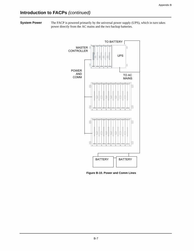
Appendix B
Introduction to FACPs (continued)
System Power The FACP is powered primarily by the universal power supply (UPS), which in turn takes power directly from the AC mains and the two backup batteries.
Figure B-10. Power and Comm Lines
BATTERY BATTERY
UPS
POWERAND
COMM
MASTER CONTROLLER
TO AC MAINS
TO BATTERY
B-7

Appendix B
Step 1. Mounting Back Boxes
Overview There are one-bay, two-bay, and three-bay back boxes. The one-bay back box is typically used as a standalone master controller cabinet, while the two- and three-bay cabinets may contain any combination of modules.
• Back boxes are usually shipped in large containers separate from the system electronics. If system electronics containers are shipped with the back box containers, store the system electronics containers in a safe, clean, and dry location until the back box installation is completed, and you are ready to install the system electronic bay(s).
• All back box PIDs are listed in Chapter 1.
Specifications Table 2-1 lists the specifications for the back boxes.
Make certain that you have the necessary hardware before you begin the installation procedure. The Back Box Mounting Hardware Kit should have all of the items listed in Table 2-2.
Table B-1. Back Box Specifications
PID Number
Description Height Width Rough Opening
Size Weight Box Trim Door Box Height Width
4100-2001/20112975-9190/9191
1 Bay 55 lb.(25 kg)
20-¾ in.(527 mm)
23-½ in.(597 mm)
26-3/8 in.(670 mm)
25-¾ in.(654 mm)
21-¼ in.(540 mm)
26 ¼ in.(667 mm)
4100-2002/20122975-9192/9193
2 Bay 125 lb.(57 kg)
36-¼ in.(921 mm)
39-1/8 in.(994 mm)
26-3/8 in.(670 mm)
25-¾ in.(654 mm)
36-¾ in.(933 mm)
26 ¼ in.(667 mm)
4100-2003/20132975-9194/9195
3 Bay 185 lb.(84 kg)
52-1/8 in.(1,324 mm)
55 in.(1,397 mm)
26-3/8 in.(670 mm)
25-¾ in.(654 mm)
52 5/8 in.(1,337 mm)
26 ¼ in.(667 mm)
Table B-2. Contents of the Back Box Mounting Hardware Kit
Part Number DescriptionQuantity per back box
1-Bay Box 2-Bay Box 3-Bay Box
268-010 Lockwasher (No. 8)
6 8 10
490-011 Washer 6 8 10
426-033 Screw (No. 8 Torx, 5/16 in.)
6 8 10
B-8
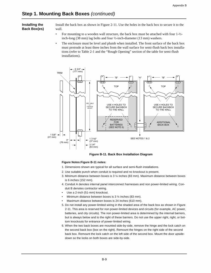
Appendix B
Step 1. Mounting Back Boxes (continued)
Installing the Back Box(es)
Install the back box as shown in Figure 2-11. Use the holes in the back box to secure it to the wall.
• For mounting to a wooden wall structure, the back box must be attached with four 1-½-inch-long (38 mm) lag bolts and four ½-inch-diameter (13 mm) washers.
• The enclosure must be level and plumb when installed. The front surface of the back box must protrude at least three inches from the wall surface for semi-flush back box installa-tions (refer to Table 2-1 and the “Rough Opening” section of the table for semi-flush installations).
Figure B-11. Back Box Installation Diagram
Figure Notes:Figure B-11 notes:
1. Dimensions shown are typical for all surface and semi-flush installations.
2. Use suitable punch when conduit is required and no knockout is present.
3. Minimum distance between boxes is 3 ¼ inches (83 mm). Maximum distance between boxes
is 6 inches (152 mm).
4. Conduit A denotes internal panel interconnect harnesses and non power-limited wiring. Con-
duit B denotes contractor wiring.
• Use a 2-inch (51-mm) knockout.
• Minimum distance between boxes is 3 ¼ inches (83 mm).
• Maximum distance between boxes is 24 inches (610 mm).
5. Do not install any power-limited wiring in the shaded area of the back box as shown in Figure
2-11. This area is reserved for non power-limited devices and circuits (for example, AC power,
batteries, and city circuits). The non power-limited area is determined by the internal barriers,
but is always below and to the right of these barriers. Do not use the upper right, right, or bot-
tom knockouts for entrance of power-limited wiring.
6. When the two back boxes are mounted side-by-side, remove the hinge and the lock catch on
the second back box (box on the right). Remount the hinges on the right side of the second
back box. Remount the lock catch on the left side of the second box. Mount the door upside-
down so the locks on both boxes are side-by-side.
TRIM6 3/4"
(171 mm)
1 7/16"(37 mm)3 1/4"(83 mm)
3"(76 mm)
1 5/8"(41 mm)
TOP TOP
RESERVEDFOR
BATTERIES(SEE NOTE 6)
ADDITIONALBACK BOX
"B"
SEE TABLE2-1
FOR BOXHEIGHT
"B"
USE 4 HOLES TOSECURE BACKBOX
TO THE WALL
"A"
SEE NOTES 3, 4, & 6
USE 4 HOLES TOSECURE BACKBOX
TO THE WALL
SEE NOTES 1 & 2
B-9
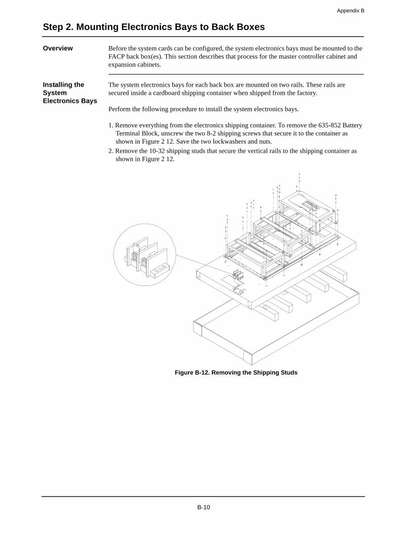
Appendix B
Step 2. Mounting Electronics Bays to Back Boxes
Overview Before the system cards can be configured, the system electronics bays must be mounted to the FACP back box(es). This section describes that process for the master controller cabinet and expansion cabinets.
Installing the System Electronics Bays
The system electronics bays for each back box are mounted on two rails. These rails are secured inside a cardboard shipping container when shipped from the factory.
Perform the following procedure to install the system electronics bays.
1. Remove everything from the electronics shipping container. To remove the 635-852 Battery Terminal Block, unscrew the two 8-2 shipping screws that secure it to the container as shown in Figure 2 12. Save the two lockwashers and nuts.
2. Remove the 10-32 shipping studs that secure the vertical rails to the shipping container as shown in Figure 2 12.
Figure B-12. Removing the Shipping Studs
B-10

Appendix B
Step 2. Mounting Electronics Bays to Back Boxes (continued)
Installing the System Electronics Bays
3. Using the hardware provided (as referenced in Table 2-2), insert a mounting screw in both the top right and top left track support holes in the back box as shown in Figure 2 13.
Figure B-13. Inserting the Mounting Screws
4. Tighten the two mounting screws, but leave a 1/8-inch (3-mm) gap from the seated position of each screw.
5. Using the vertical rails as handles, carefully lift the system electronics bay assembly (and the terminal block) from the shipping container.
Continued on next page
MOUNTING SCREWS
BACK BOX
B-11

Appendix B
Step 2. Mounting Electronics Bays to Back Boxes (continued)
Installing the System Electronics Bays
6. Install the system electronics bay assembly in the back box by carefully placing the rail tear-drop holes (located at the top of the rails) onto the two extended screws in the back box, allowing the electronics bay assembly to hang from the screws. See Figure 2 14.
Note: Make sure you do not pinch the terminal block wiring behind the rails as you mount the bay assembly in the back box.
Figure B-14. Installing the System Electronics Bay Assembly7. Insert the remaining mounting screws through the screw holes in the rails.8. Securely tighten all mounting screws. Refer to Table 2-3 for the recommended torque.
Continued on next page
Table B-3. Recommended Torque for Mounting Hardware
Screw / Nut Size Recommended Torque
No.6 7.9 to 8.7 inch/ounces(569 to 626 cm/grams)
No.8 16.1 to 17.8 inch/ounces(1,159 to 1,282 cm/grams)
No.10 26.8 to 29.7 inch/ounces(1,930 to 2,139 cm/grams)
TEARDROP HOLES
SYSTEM ELECTRONICSBAY ASSEMBLY
BACK BOX
TERMINAL BLOCK
LOCKWASHER
NUT
SCREW HOLES
PREMOUNTED SCREWS
B-12

Appendix B
Step 2. Mounting Electronics Bays to Back Boxes (continued)
Installing the System Electronics Bays
9. Place the 635-852 terminal block on the two mounting studs on the right side of the back box as shown in Figure 2 14.
10. Secure the 635-852 Terminal Block using the two lockwashers and nuts that you set aside in step 1. Use the torque recommendations listed in Table 2-3 when securing the terminal block.
At this point, the system is ready for system card installation.
CAUTION: Do not apply power to the system at this time.
For more detailed system installation instructions, refer to one of the following publications:
• 4100+/4120/UT System Cards Installation Instructions: FA4-21-305 (574-038)
• 4100+ Contractor Installation Instructions: FA4-21-202 (574-019)
• UT Contractor Installation Instructions: FA4-21-300 (574-901)
B-13
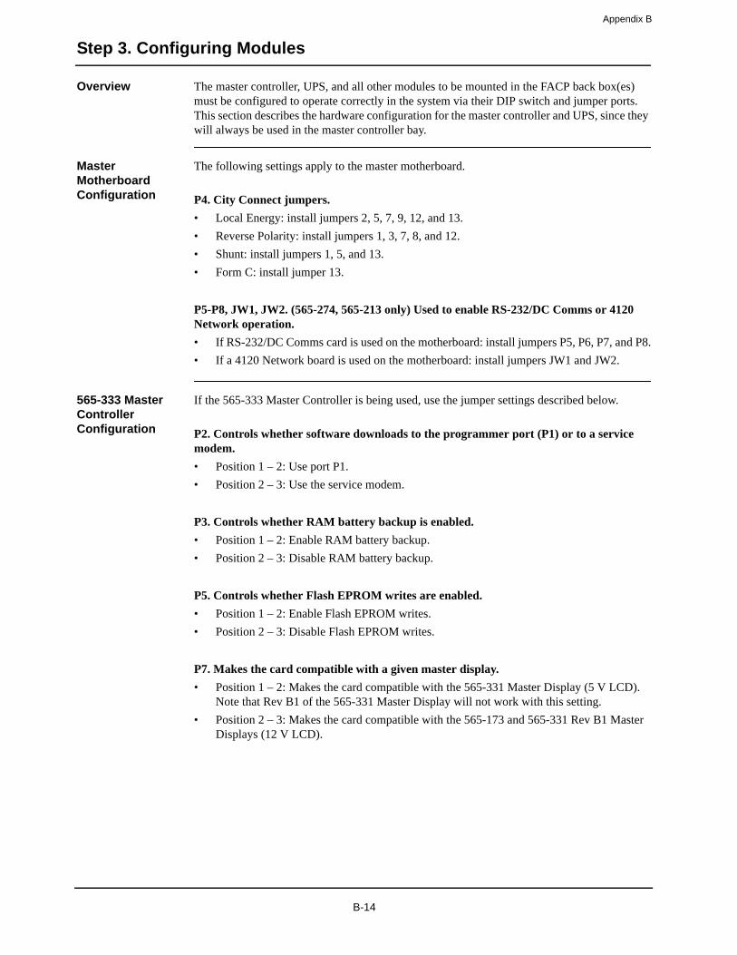
Appendix B
Step 3. Configuring Modules
Overview The master controller, UPS, and all other modules to be mounted in the FACP back box(es) must be configured to operate correctly in the system via their DIP switch and jumper ports. This section describes the hardware configuration for the master controller and UPS, since they will always be used in the master controller bay.
Master Motherboard Configuration
The following settings apply to the master motherboard.
P4. City Connect jumpers.
• Local Energy: install jumpers 2, 5, 7, 9, 12, and 13.
• Reverse Polarity: install jumpers 1, 3, 7, 8, and 12.
• Shunt: install jumpers 1, 5, and 13.
• Form C: install jumper 13.
P5-P8, JW1, JW2. (565-274, 565-213 only) Used to enable RS-232/DC Comms or 4120 Network operation.
• If RS-232/DC Comms card is used on the motherboard: install jumpers P5, P6, P7, and P8.
• If a 4120 Network board is used on the motherboard: install jumpers JW1 and JW2.
565-333 Master Controller Configuration
If the 565-333 Master Controller is being used, use the jumper settings described below.
P2. Controls whether software downloads to the programmer port (P1) or to a service modem.
• Position 1 – 2: Use port P1.
• Position 2 – 3: Use the service modem.
P3. Controls whether RAM battery backup is enabled.
• Position 1 – 2: Enable RAM battery backup.
• Position 2 – 3: Disable RAM battery backup.
P5. Controls whether Flash EPROM writes are enabled.
• Position 1 – 2: Enable Flash EPROM writes.
• Position 2 – 3: Disable Flash EPROM writes.
P7. Makes the card compatible with a given master display.
• Position 1 – 2: Makes the card compatible with the 565-331 Master Display (5 V LCD). Note that Rev B1 of the 565-331 Master Display will not work with this setting.
• Position 2 – 3: Makes the card compatible with the 565-173 and 565-331 Rev B1 Master Displays (12 V LCD).
B-14
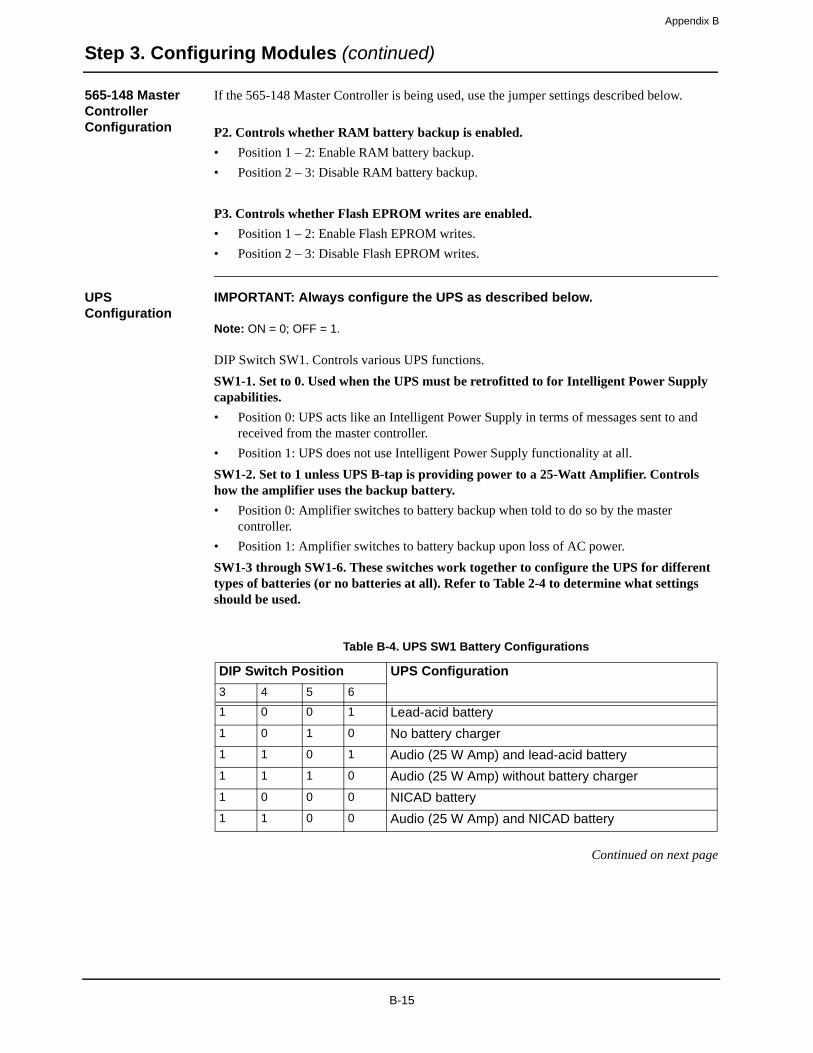
Appendix B
Step 3. Configuring Modules (continued)
565-148 Master Controller Configuration
If the 565-148 Master Controller is being used, use the jumper settings described below.
P2. Controls whether RAM battery backup is enabled.
• Position 1 – 2: Enable RAM battery backup.
• Position 2 – 3: Disable RAM battery backup.
P3. Controls whether Flash EPROM writes are enabled.
• Position 1 – 2: Enable Flash EPROM writes.
• Position 2 – 3: Disable Flash EPROM writes.
UPS Configuration
IMPORTANT: Always configure the UPS as described below.
Note: ON = 0; OFF = 1.
DIP Switch SW1. Controls various UPS functions.
SW1-1. Set to 0. Used when the UPS must be retrofitted to for Intelligent Power Supply capabilities.
• Position 0: UPS acts like an Intelligent Power Supply in terms of messages sent to and received from the master controller.
• Position 1: UPS does not use Intelligent Power Supply functionality at all.
SW1-2. Set to 1 unless UPS B-tap is providing power to a 25-Watt Amplifier. Controls how the amplifier uses the backup battery.
• Position 0: Amplifier switches to battery backup when told to do so by the master controller.
• Position 1: Amplifier switches to battery backup upon loss of AC power.
SW1-3 through SW1-6. These switches work together to configure the UPS for different types of batteries (or no batteries at all). Refer to Table 2-4 to determine what settings should be used.
Continued on next page
Table B-4. UPS SW1 Battery Configurations
DIP Switch Position UPS Configuration
3 4 5 6
1 0 0 1 Lead-acid battery
1 0 1 0 No battery charger
1 1 0 1 Audio (25 W Amp) and lead-acid battery
1 1 1 0 Audio (25 W Amp) without battery charger
1 0 0 0 NICAD battery
1 1 0 0 Audio (25 W Amp) and NICAD battery
B-15
Appendix B
Step 3. Configuring Modules (continued)
UPS Configuration
SW1-7. Controls battery charging current.
• Position 0: 50 Ah battery charging.
• Position 1: 110 Ah battery charging.
SW1-8. Not used.
DIP Switch SW2. Device address DIP switch. See Appendix A for details.
Use the following jumper settings to continue configuring the UPS.
P6. Battery backup configuration.
• Position 1 – 2: Normal configuration (battery backup).
• Position 2 – 3: No battery backup.
IMPORTANT: Do not use jumper P6 to bypass troubles from a temporarily disconnected battery.
P7. Amplifier shutdown selection.
• Position 1 – 2: Tap A shutdown enabled.
• Position 3 – 4: Tap B shutdown enabled.
• Position 5 – 6: Tap C shutdown enabled.
P16. Controls Earth Detect configuration.
• Position 1 – 2: Enable Earth Detect.
• Position 2 – 3: Disable Earth Detect.
Note: Jumpers P10, P13, and JW1 through JW7 are not field adjustable.
Configuring Other Cards
Refer to 4100/4100+ Fire Alarm Universal Transponder (UT) Service Instructions (FA4-51-207) to configure other cards that are located in master controller bays and expansion bays.
B-16
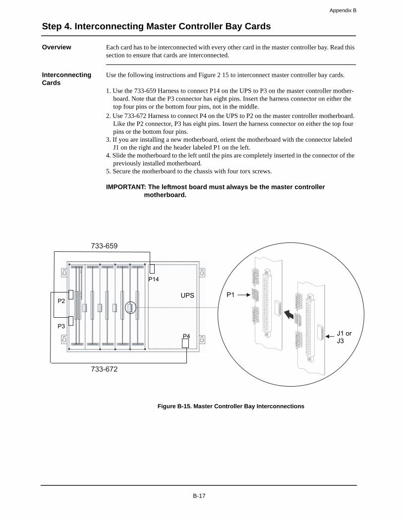
Appendix B
Step 4. Interconnecting Master Controller Bay Cards
Overview Each card has to be interconnected with every other card in the master controller bay. Read this section to ensure that cards are interconnected.
Interconnecting Cards
Use the following instructions and Figure 2 15 to interconnect master controller bay cards.
1. Use the 733-659 Harness to connect P14 on the UPS to P3 on the master controller mother-board. Note that the P3 connector has eight pins. Insert the harness connector on either the top four pins or the bottom four pins, not in the middle.
2. Use 733-672 Harness to connect P4 on the UPS to P2 on the master controller motherboard. Like the P2 connector, P3 has eight pins. Insert the harness connector on either the top four pins or the bottom four pins.
3. If you are installing a new motherboard, orient the motherboard with the connector labeled J1 on the right and the header labeled P1 on the left.
4. Slide the motherboard to the left until the pins are completely inserted in the connector of the previously installed motherboard.
5. Secure the motherboard to the chassis with four torx screws.
IMPORTANT: The leftmost board must always be the master controller motherboard.
Figure B-15. Master Controller Bay Interconnections
UPS
P14
P4
P2
P3J1 or J3
P1
733-659
733-672
B-17
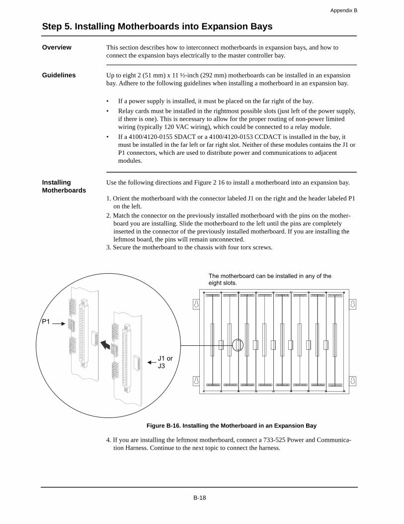
Appendix B
Step 5. Installing Motherboards into Expansion Bays
Overview This section describes how to interconnect motherboards in expansion bays, and how to connect the expansion bays electrically to the master controller bay.
Guidelines Up to eight 2 (51 mm) x 11 ½-inch (292 mm) motherboards can be installed in an expansion bay. Adhere to the following guidelines when installing a motherboard in an expansion bay.
• If a power supply is installed, it must be placed on the far right of the bay.
• Relay cards must be installed in the rightmost possible slots (just left of the power supply, if there is one). This is necessary to allow for the proper routing of non-power limited wiring (typically 120 VAC wiring), which could be connected to a relay module.
• If a 4100/4120-0155 SDACT or a 4100/4120-0153 CCDACT is installed in the bay, it must be installed in the far left or far right slot. Neither of these modules contains the J1 or P1 connectors, which are used to distribute power and communications to adjacent modules.
Installing Motherboards
Use the following directions and Figure 2 16 to install a motherboard into an expansion bay.
1. Orient the motherboard with the connector labeled J1 on the right and the header labeled P1 on the left.
2. Match the connector on the previously installed motherboard with the pins on the mother-board you are installing. Slide the motherboard to the left until the pins are completely inserted in the connector of the previously installed motherboard. If you are installing the leftmost board, the pins will remain unconnected.
3. Secure the motherboard to the chassis with four torx screws.
Figure B-16. Installing the Motherboard in an Expansion Bay
4. If you are installing the leftmost motherboard, connect a 733-525 Power and Communica-tion Harness. Continue to the next topic to connect the harness.
The motherboard can be installed in any of the eight slots.
J1 or J3
P1
B-18
Appendix B
Step 5. Installing Motherboards into Expansion Bays (continued)
Connecting the 733-525 Harness
If you need to connect a 733-525 Harness to a motherboard, refer to Figure 2 17 and follow these steps. Make sure to route the power and communication wiring on the left side of the bay.
1. Connect one end of the harness to a motherboard in an adjacent bay.
If the adjacent bay is a master controller bay, connect the harness to the P2 and P3 connec-tors of the master controller motherboard and continue to step 2.
If the adjacent bay is an expansion bay, connect the harness to the P2 and P3 connectors of the motherboard installed in the leftmost slot. (If a 4100/4120-0155 SDACT or a 4100/4120-0153 CCDACT occupies the leftmost slot, connect the harness to the motherboard in the second slot from the left.) Connect the harness as follows:
a. Insert the harness connector with the blue wire into the P2 connector. Note that the P2 connector has eight pins. Insert the harness connector on either the top four pins or the bottom four pins, not in the middle.
b. Insert the harness connector with the white wire into the P3 connector. Note that the P3 connector has eight pins. Insert the harness connector on either the top four pins or the bottom four pins, not in the middle.
Continued on next page
B-19
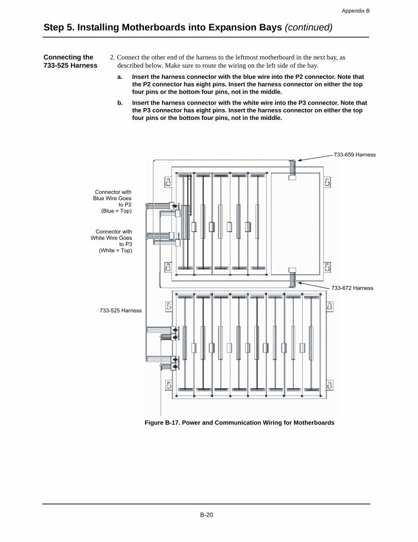
Appendix B
Step 5. Installing Motherboards into Expansion Bays (continued)
Connecting the 733-525 Harness
2. Connect the other end of the harness to the leftmost motherboard in the next bay, as described below. Make sure to route the wiring on the left side of the bay.
a. Insert the harness connector with the blue wire into the P2 connector. Note that the P2 connector has eight pins. Insert the harness connector on either the top four pins or the bottom four pins, not in the middle.
b. Insert the harness connector with the white wire into the P3 connector. Note that the P3 connector has eight pins. Insert the harness connector on either the top four pins or the bottom four pins, not in the middle.
Figure B-17. Power and Communication Wiring for Motherboards
Connector with Blue Wire Goes
to P2 (Blue = Top)
Connector with White Wire Goes
to P3(White = Top)
733-525 Harness
733-659 Harness
733-672 Harness
B-20
Appendix C Installing 4100 MINIPLEX Components (Non-4100ES/4100U)
Introduction MINIPLEX remote interface cards (RICs) allow for data and power interconnections between the 4100 host panel and remote locations. This chapter describes the transponder installation procedure for all MINIPLEX systems in non-4100ES/4100U systems.
In this chapter This chapter covers the following topics:
Topic Page
Introduction to MINIPLEX Systems C-2
MINIPLEX System Components C-4
MINIPLEX System Guidelines C-6
Installing Modules into Back Boxes C-7
MINIPLEX Wiring C-11
C-1

Appendix C
Introduction to MINIPLEX Systems
Overview The 4100 MINIPLEX Fire Alarm System uses transponder cabinets containing remote interface cards (RICs) to extend power and communication across large areas. MINIPLEX transponders allow the system to provide applications for up to 1000 monitor and/or control points and 2000 annunciator points (see note). Using 4100-style serial communications, up to 31 distributed MINIPLEX transponder locations are possible for initiating device circuit cards, MAPNET II/ TrueAlarm addressable communications interfaces, notification appliance circuit cards, LED/switch controls, auxiliary relay control cards, power supplies, and audio amplifiers.
By selecting the required combinations of modules and mounting MINIPLEX transponders at the appropriate building locations, wire quantities are significantly reduced for all monitor and control functions. Since power for the local modules is provided from the local power supply, the wiring from the control panel need only be separate twisted, shielded pairs for data, voice, and telephone.
Notes:
• One point consists of one LED or one switch on an LED/switch module, one LED driver output on a graphic driver, or one switch input on a graphic switch input module.
• Up to 32 modules can be controlled by one MINIPLEX transponder.
• The 4100 0117 MINIPLEX Expansion Power Supply is available with a power-limited 8 A output.
Continued on next page
C-2

Appendix C
Introduction to MINIPLEX Systems (continued)
Overview Figure C-1 is an outline of a MINIPLEX system.
Figure C-1. MINIPLEX System Design
Seventh floor
Sixth floor
Fifth floor
Fourth floor
Third floor
Second floor
First floor
Speaker NAC
TrueAlarm sensorsand MAPNET IIaddressable circuits
RUI communicationswiring, twisted,shielded pair
Audio riser wiring,twisted pair
Legend:
MINIPLEX transponderwith solid door
MINIPLEX transponder withLED/switch modules on door panel
FACP
ACKNOWLEDGE
C-3
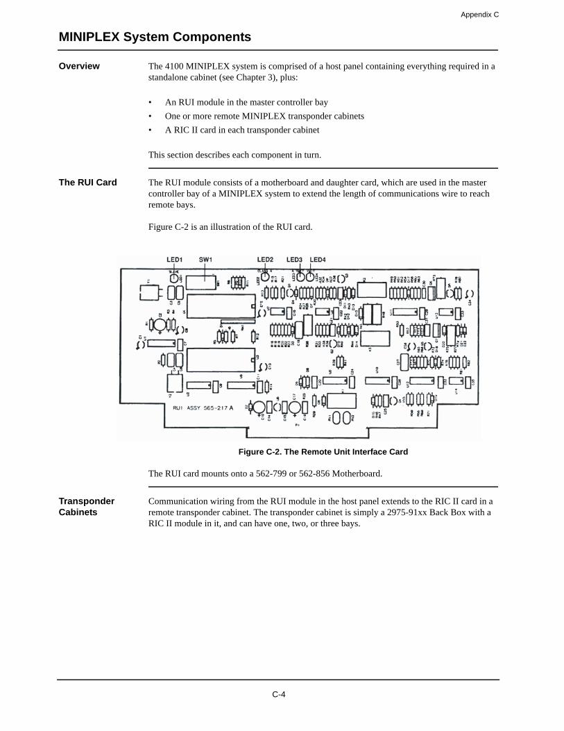
Appendix C
MINIPLEX System Components
Overview The 4100 MINIPLEX system is comprised of a host panel containing everything required in a standalone cabinet (see Chapter 3), plus:
• An RUI module in the master controller bay
• One or more remote MINIPLEX transponder cabinets
• A RIC II card in each transponder cabinet
This section describes each component in turn.
The RUI Card The RUI module consists of a motherboard and daughter card, which are used in the master controller bay of a MINIPLEX system to extend the length of communications wire to reach remote bays.
Figure C-2 is an illustration of the RUI card.
Figure C-2. The Remote Unit Interface Card
The RUI card mounts onto a 562-799 or 562-856 Motherboard.
Transponder Cabinets
Communication wiring from the RUI module in the host panel extends to the RIC II card in a remote transponder cabinet. The transponder cabinet is simply a 2975-91xx Back Box with a RIC II module in it, and can have one, two, or three bays.
C-4

Appendix C
MINIPLEX System Components (continued)
The Remote Interface Card (RIC)
Remote interface cards (RICs) in the transponder cabinets allow for data, power, and audio interconnections between the 4100 host panel and remote locations. They support RUI connections in Style 4 and Style 7 wiring configurations.
Figure C-3 illustrates the RIC circuit board.
Figure C-3. The RIC II Card
TB2 LED1
TBL+COMMPRIM+COMMPRIM
-COMM
-COMM
+COMM
+COMM
24C
24C
PIEZOCTRLLEDCTRL
PTT+
PTT-
SHLD
GRNCIM
WHT
COMMS TROUBLE LED (LED 1): Lights if there is a line short on either primary or secondary lines, or if both comms inputs are absent.
POWER/COMM TERMINAL BLOCK (TB1)
HEADER CONNECTOR (J1)
SEC
+24 V
+24 V
8
1
PIEZO/MICROPHONE TERMINAL BLOCK (TB2)
REMOTE MICROPHONE CONNECTOR (P1)
C-5

Appendix C
MINIPLEX System Guidelines
Overview The rules on this page apply exclusively to MINIPLEX systems. Review each guideline before installing a MINIPLEX 4100 system.
Guidelines • The MINIPLEX master control panel must be a 4100-8210 Voice and Sound Control Panel.
• The Style 4 RUI card supports MINIPLEX transponders and 4602/4603 serial annuncia-tors on the same signaling line circuit.
• Up to 4 RUI cards in the 4100 Control Panel can be used for distributing transponder wiring in different directions or for supporting different wiring requirements (such as using a Style 7 RUI for serial annunciators).
• Up to 31 MINIPLEX transponders can be controlled from the 4100 Control Panel, and can be distributed as required among the RUI cards.
• “T” tapping is allowed for Style 4 communications only (Style 7 wiring does not support “T” tapping).
• Wiring from RUI cards is a minimum of 18 AWG twisted, shielded pair.
• The maximum wiring distance from the 4100 RUI card to a MINIPLEX transponder is 2500 feet (762 m). For Style 4 wiring, this can be extended to 10,000 feet (3 km) maximum if “T” tapping is used.
• Voice and telephone wiring for 4100-8210 systems is via separate twisted, shielded pairs.
• 4100U system cards are not compatible with 4100 miniplex transponders that are controlled by a 4100 RIC II card.
C-6
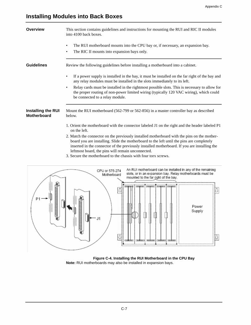
Appendix C
Installing Modules into Back Boxes
Overview This section contains guidelines and instructions for mounting the RUI and RIC II modules into 4100 back boxes.
• The RUI motherboard mounts into the CPU bay or, if necessary, an expansion bay.
• The RIC II mounts into expansion bays only.
Guidelines Review the following guidelines before installing a motherboard into a cabinet.
• If a power supply is installed in the bay, it must be installed on the far right of the bay and any relay modules must be installed in the slots immediately to its left.
• Relay cards must be installed in the rightmost possible slots. This is necessary to allow for the proper routing of non-power limited wiring (typically 120 VAC wiring), which could be connected to a relay module.
Installing the RUI Motherboard
Mount the RUI motherboard (562-799 or 562-856) in a master controller bay as described below.
1. Orient the motherboard with the connector labeled J1 on the right and the header labeled P1 on the left.
2. Match the connector on the previously installed motherboard with the pins on the mother-board you are installing. Slide the motherboard to the left until the pins are completely inserted in the connector of the previously installed motherboard. If you are installing the leftmost board, the pins will remain unconnected.
3. Secure the motherboard to the chassis with four torx screws.
Figure C-4. Installing the RUI Motherboard in the CPU BayNote: RUI motherboards may also be installed in expansion bays.
C-7

Appendix C
Installing Modules into Back Boxes (continued)
Installing the RIC II Motherboard
The RIC II motherboard is installed into a remote transponder cabinet (back box PID series 2975-91xx). Review the following guidelines before mounting RIC II motherboard.
• If a power supply is installed in the bay, it must be installed on the far right of the bay and any relay modules must be installed in the slots immediately to its left.
• Relay cards must be installed in the rightmost possible slots. This is necessary to allow for the proper routing of non-power limited wiring (typically 120 VAC wiring), which could be connected to a relay module.
• If a 4100/4120-0155 SDACT or a 4100/4120-0153 CCDACT is installed in the bay, it must be installed in the far left or far right slot. Neither of these modules contains the J1 or P1 connectors, which are used to distribute power and communications to adjacent modules.
Use the following directions and Figure 4-5 to install a RIC II motherboard into a transponder cabinet.
1. The RIC II motherboard must be installed in the leftmost slot. Orient the motherboard with the connector labeled J1 on the right.
2. Secure the motherboard to the chassis with four torx screws.
Figure C-5. Installing the RIC II Motherboard into a 4100 Expansion Bay
3. If you are installing the RIC II in a transponder cabinet with additional bays, you must con-nect a 733-525 Power and Communication Harness. Continue to the next topic for instruc-tions.
The RIC II motherboard must be installed in the leftmost slot.
RIC II
J1
C-8

Appendix C
Installing Modules into Back Boxes (continued)
Connecting the 733-525 Harness
If you need to connect a 733-525 Harness to a motherboard, refer to Figure 4-6 and follow these steps. Make sure to route the power and communication wiring on the left side of the bay.
1. Connect one end of the harness to a motherboard in an adjacent bay.
If the adjacent bay is a master controller bay, connect the harness to the P2 and P3 connec-tors of the master controller motherboard and continue to step 2.
If the adjacent bay is an expansion bay, connect the harness to the P2 and P3 connectors of the motherboard installed in the leftmost slot. (If a 4100/4120-0155 SDACT or a 4100/4120-0153 CCDACT occupies the leftmost slot, connect the harness to the motherboard in the second slot from the left.) Connect the harness as follows:
a. Insert the harness connector with the blue wire into the P2 connector. Note that the P2 connector has eight pins. Insert the harness connector on either the top four pins or the bottom four pins, not in the middle.
b. Insert the harness connector with the white wire into the P3 connector. Note that the P3 connector has eight pins. Insert the harness connector on either the top four pins or the bottom four pins, not in the middle.
Continued on next page
C-9
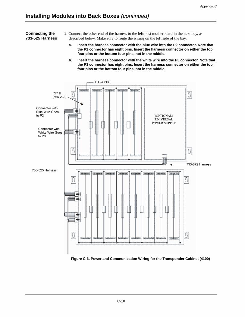
Appendix C
Installing Modules into Back Boxes (continued)
Connecting the 733-525 Harness
2. Connect the other end of the harness to the leftmost motherboard in the next bay, as described below. Make sure to route the wiring on the left side of the bay.
a. Insert the harness connector with the blue wire into the P2 connector. Note that the P2 connector has eight pins. Insert the harness connector on either the top four pins or the bottom four pins, not in the middle.
b. Insert the harness connector with the white wire into the P3 connector. Note that the P3 connector has eight pins. Insert the harness connector on either the top four pins or the bottom four pins, not in the middle.
Figure C-6. Power and Communication Wiring for the Transponder Cabinet (4100)
Connector with Blue Wire Goes to P2
Connector with White Wire Goes to P3
733-525 Harness
RIC II (565-233)
733-672 Harness
TO 24 VDC
(OPTIONAL) UNIVERSAL
POWER SUPPLY
C-10
Appendix C
MINIPLEX Wiring
Overview The RIC must be connected to the host panel via RUI cabling. This section explains how to wire the two together, and how to set up a system with multiple transponders connected to the same host panel.
Wiring Configurations
RUI cabling can be accomplished either through Class A or Class B wiring.
Class A wiring allows transponder cabinets to communicate with the FACP even in the event of an open circuit somewhere in the loop. Class A wiring requires that two wires are routed from the CPU motherboard to each RIC, and then back again to the CPU motherboard.
Class B wiring allows “T” tapping, and therefore requires less wiring distance per installation than Class A. Additionally, Class B wiring does not require end-of-line resistors, because each RIC communicates directly to the CPU.
IMPORTANT: Make sure these prerequisites are accounted for before wiring:
• All transponder cabinets are installed within 2500 feet (762 m) of the FACP.
• Conductors test free of all grounds.
• All wires are between 12 (3.309 mm2) and 18 AWG (0.8321 mm2), or as the local code dictates.
Class A Wiring To connect the RUI card to RICs using Class A wiring, read the following instructions and refer to Figure 4-7, on the next page.
1. Route wire between 12 (3.309 mm2) and 18 AWG (0.8321 mm2) from the + (TB1-8) and - (TB1-6) terminals on the COMMS “A” block of the 562-856/565-217 RUI card to the TB1-8 (+) and TB1-6 (-) terminals on the 565-233 RIC.
2. Route wire from the first RIC to the next one. Repeat for each transponder cabinet within 2500 feet (762 m).
3. Route wire from TB1-7 (+) and TB1-5 (-) on the last RIC to + (TB1-4) and - (TB1-2) on the COMMS “B” block of the 562-856/565-217 RUI card.
Class B Wiring To connect the RUI card to RIC II cards using Class B wiring, read the following instructions and refer to Figure 4-7, on the next page.
1. Route wire between 12 (3.309 mm2) and 18 AWG (0.8321 mm2) from the + (TB1-8) and - (TB1-6) terminals on the COMMS “A” block of the 562-856/565-217 RUI card to the TB1-8 (+) and TB1-6 (-) terminals on the 565-233 RIC.
2. Route wire from the first RIC to the next one. Repeat for each transponder cabinet within 2500 feet (762 m).
C-11
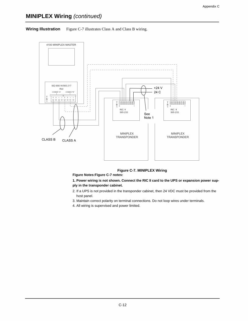
Appendix C
MINIPLEX Wiring (continued)
Wiring Illustration Figure C-7 illustrates Class A and Class B wiring.
Figure C-7. MINIPLEX WiringFigure Notes:Figure C-7 notes:
1. Power wiring is not shown. Connect the RIC II card to the UPS or expansion power sup-
ply in the transponder cabinet.
2. If a UPS is not provided in the transponder cabinet, then 24 VDC must be provided from the
host panel.
3. Maintain correct polarity on terminal connections. Do not loop wires under terminals.
4. All wiring is supervised and power limited.
4100 MINIPLEX MASTER
RIC 11565-233
MINIPLEXTRANSPONDER
562-856 W/565-217
COMMS "A"
8 1
COMMS "B"
RUI
TB1 T
B1
RIC 11565-233
MINIPLEXTRANSPONDER
8 1
TB1
CLASS ACLASS B
+24 V24 C
SeeNote 1
II II
C-12

Appendix DChecking System Wiring
Overview This appendix contains instructions on how to use a volt/ohm meter to check system wiring.
Using the Volt/ Ohm Meter
When using the volt/ohm meter to check each circuit, make sure to adhere to the notes and instructions below.
Note:
• Ensure that no power is applied to the 4100 fire alarm panel and that all wiring is properly connected (terminal blocks, LED/switch module ribbon cables, etc.).
• Use the green grounding lug in the control panel for all measurements to ground.
• Each circuit must test free of all grounds and extraneous voltages.
Use the volt/ohm meter as described in the steps below to check each circuit type.
1. At the control panel, locate wires from each initiating device or indicating appliance circuit.
2. Check each circuit for extraneous voltage by setting the volt/ohm meter to 300 VAC. Place the meter probes so that the black probe is on the “-” wire and the red probe is on the “+” wire. Meter readings must show 0 volts (see Figure D-1A).
3. Set the volt/ohm meter to 60 VDC and repeat step 2. The meter must read 0 volts (see Figure D-1A).
4. Set the volt/ohm meter to OHMS x 10 and place the meter probes as described in step 2. Check the circuits using the resis-tance measurements in Table D-1. Locate and correct any abnor-mal conditions at this time. Note: If the reading indicates an open circuit in an initiating circuit, make sure the smoke detec-tor heads are properly mounted and seated. The circuit may be open if smoke detector power is not present, and if separately powered 4-wire devices are used.
5. Check all other system wiring to verify that each circuit is free of grounds and extraneous voltages.
Figure D-1. Volt/OHM Meter Readings
D-1
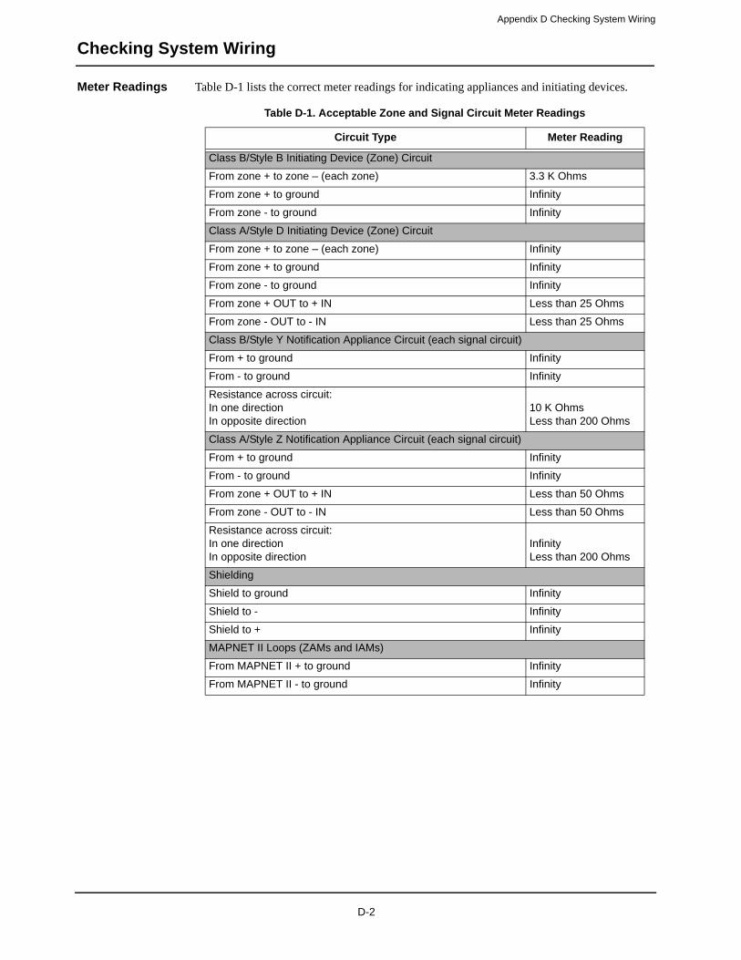
Appendix D Checking System Wiring
Checking System Wiring
Meter Readings Table D-1 lists the correct meter readings for indicating appliances and initiating devices.
Table D-1. Acceptable Zone and Signal Circuit Meter Readings
Circuit Type Meter Reading
Class B/Style B Initiating Device (Zone) Circuit
From zone + to zone – (each zone) 3.3 K Ohms
From zone + to ground Infinity
From zone - to ground Infinity
Class A/Style D Initiating Device (Zone) Circuit
From zone + to zone – (each zone) Infinity
From zone + to ground Infinity
From zone - to ground Infinity
From zone + OUT to + IN Less than 25 Ohms
From zone - OUT to - IN Less than 25 Ohms
Class B/Style Y Notification Appliance Circuit (each signal circuit)
From + to ground Infinity
From - to ground Infinity
Resistance across circuit:In one directionIn opposite direction
10 K OhmsLess than 200 Ohms
Class A/Style Z Notification Appliance Circuit (each signal circuit)
From + to ground Infinity
From - to ground Infinity
From zone + OUT to + IN Less than 50 Ohms
From zone - OUT to - IN Less than 50 Ohms
Resistance across circuit:In one directionIn opposite direction
InfinityLess than 200 Ohms
Shielding
Shield to ground Infinity
Shield to - Infinity
Shield to + Infinity
MAPNET II Loops (ZAMs and IAMs)
From MAPNET II + to ground Infinity
From MAPNET II - to ground Infinity
D-2

Appendix E
References to 4100ES Module Installation Instructions
Overview .
Table E-1. References to 4100ES module installation instructions
PID Description Installation Instructions
4100-0156 8V DC CONVERTER 574-123
4100-0620 TRANSPONDER IF MODULE 574-848
4100-0621 ANALOG AUDIO RISER MODULE 574-848
4100-0622 DIGITAL AUDIO RISER MODULE 574-848
4100-0623 NETWORK AUDIO I/F MODULE 574-848
4100-0625 LOCAL MODE TPR IF 574-848
4100-0632 UTILITY BLOC, 16 TERMINALS 579-248
4100-0633 TRANSPONDER TAMPER SWITCH 579-195
4100-0634 POWER DIST MODULE 120V 574-848
4100-0635 POWER DIST MODULE 220V 574-848
4100-1210 ANALOG AUDIO CONTROLLER 579-159
4100-1240 AUX AUDIO INPUT MODULE 579-160
4100-1241 MESSAGE EXPANSION, 8 MINUTES 579-172
4100-1242 MESSAGE EXPANSION, 32 MINUTES 579-172
4100-1245 FLEX 50 NAC EXPANSION, 3 CLS B 579-175
4100-1246 FLEX 50 CLASS A ADAPTER 579-175
4100-1248 100W NAC EXPANSION, 6 CLASS B 579-175
4100-1249 100W CLASS A ADAPTER 579-175
4100-1252 AUDIO IF MODULE, SGL CHANNEL 579-168
4100-1253 AUDIO IF MODULE MULTI-CHANNEL 579-168
4100-1254 AUDIO IF 2 CHANNEL 579-168
4100-1255 AUDIO IF 3-8 CHANNEL 579-168
4100-1259 CONSTANT SUPV NAC 25V RMS A/B 579-515
4100-1259 CONSTANT SUPV NAC 25V RMS A/B -Non-Alarm Audio Mode
579-515
4100-1260 CONSTANT SUPV NAC 70V RMS A/B 579-515
4100-1260 CONSTANT SUPV NAC 70V RMS A/B - Non-Alarm Audio Mode
579-515
4100-1265 FAIL SAFE MICROPHONE MASTER 579-571
4100-1266 EXPANSION NAC CARD FOR EXP SIG 579-175
4100-1267 EXP SIG CARD CLASS A 579-175
4100-1268 EXP SIGCARD CONSTANT SUPV 579-515
4100-1269 FAIL SAFE MICROPHONE SLAVE 579-571
4100-1270 MASTER TELEPHONE, 3 NACS 579-226
4100-1271 REMOTE MASTER PHONE 579-226
4100-1272 EXPANSION PHONE CONTROLLER 579-226
4100-1273 PHONE CLASS A NAC ADAPTER 579-226
4100-1274 MICROPHONE MUX MODULE 579-879
4100-1276 8 RED PLUGGABLE LED MODULE 574-843
4100-1277 16 RED/YEL PLUGGABLE LED MOD 574-843
4100-1278 16 SW/16 RED/YEL PLUG LED 574-843
4100-1279 2” BLANK DISPLAY MODULE 574-843
4100-1280 8 SWITCH, 8 RED LED MODULE 574-843
E-1

Appendix E References to 4100ES Module Installation Instructions
4100-1281 8 SWITCH, 8 YELLOW LED MODULE 574-843
4100-1282 8 SW, 16RED/YEL LED MOUDLE 574-843
4100-1283 8 SWITCH, 16 YELLOW LED MODULE 574-843
4100-1284 8 SW, 16 RED/GREEN LED MODULE 574-843
4100-1285 16 SWITCH, 16 RED LED MODULE 574-843
4100-1286 HOA MODULE 24SWI/24RED LED 574-843
4100-1287 24 SWITCH, 24 RED LED MODULE 574-843
4100-1288 64/64 LED/SWITCH CONTROLLER 574-843
4100-1289 EXPANSION 64/64 LED/SW MODULE 574-843
4100-1290 24 POINT I/O MODULE 579-183
4100-1291 REMOTE UNIT INTERFACE (RUI) 579-213
4100-1292 REM PANEL MOUNT LCD ANUCIATOR (Backlight On) 579-265
4100-1292 REM PANEL MOUNT LCD ANUCIATOR (Backlight Off) 579-265
4100-1293 PANEL MOUNT PRINTER 579-249
4100-1295 HOA MODULE,NO TEXT,24SW/24LED 574-843
4100-1296 8 SW, 16 GREEN/ YELLOW LED MOD. 574-843
4100-1297 TFX PHONE CARD 579-862
4100-1298 4100U/4100ES MASTER FIREFIGHTER PHONE ASSEMBLY w/TFX Phone Card 579-862
4100-1311 AUDIO CONTROL BOARD - DIGITAL 579-159
4100-1312 50W AMP W/3 CLASS B NACS 25V 579-173
4100-1313 50W AMP W/3 CLASS B NACS 70V 579-173
4100-1314 100W AMP W/6 B NACS 120VAC 25V 579-174
4100-1315 100W AMP W/6 B NACS 120VAC 70V 579-174
4100-1316 100W AMP,6NAC,120VAC,25V-CAN 579-174
4100-1317 100W AMP,6NAC, 120VAC, 70V-CAN 579-174
4100-1318 100W AMP,6NAC,220/30/40VAC,25V 579-174
4100-1319 100W AMP,6NAC,220/30/40VAC,70V 579-174
4100-1320 BACKUP 100W AMP - 120VAC 25V 579-174
4100-1321 BACKUP 100W AMP - 120VAC 70V 579-174
4100-1322 BACKUP 100W AMP-120VAC 25V-C 579-174
4100-1323 BACKUP 100W AMP-120VAC 70V-C 579-174
4100-1324 BACK 100W AMP-220/240VAC,25V 579-174
4100-1325 BACK 100W AMP-220/240VAC,70V 579-174
Table E-1. References to 4100ES module installation instructions (Continued)
PID Description Installation Instructions
References to 4100ES Module Installation Instructions
E-2
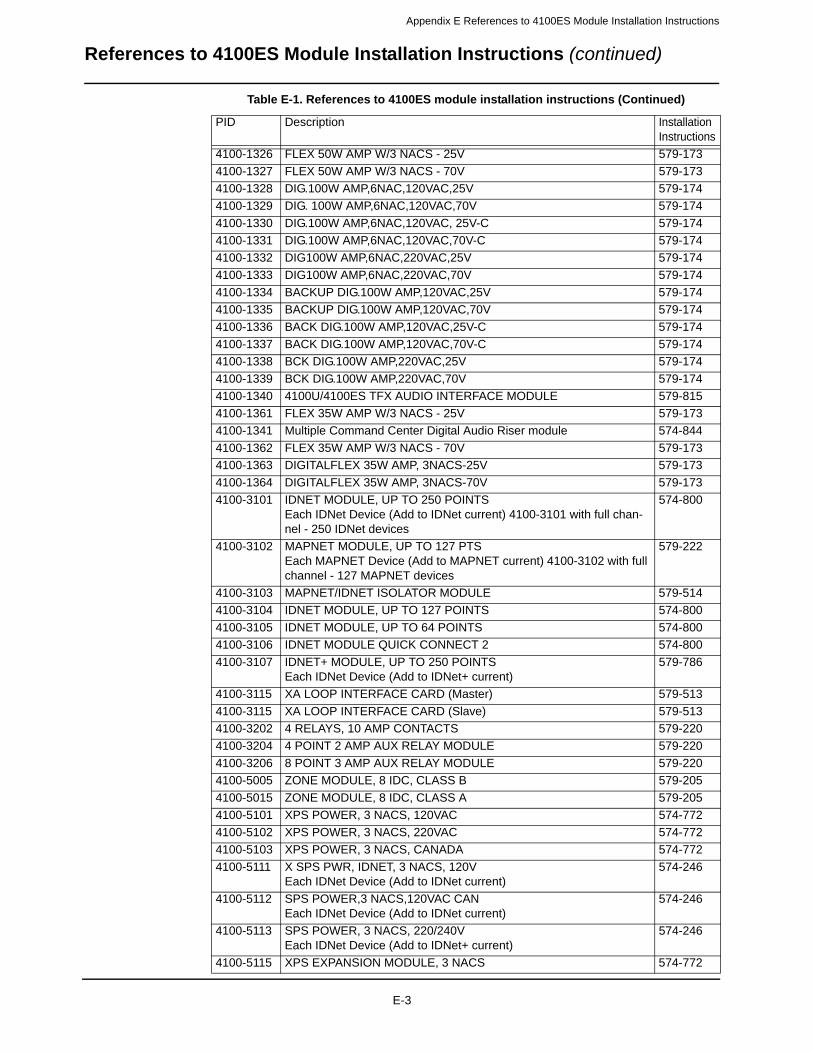
Appendix E References to 4100ES Module Installation Instructions
4100-1326 FLEX 50W AMP W/3 NACS - 25V 579-173
4100-1327 FLEX 50W AMP W/3 NACS - 70V 579-173
4100-1328 DIG.100W AMP,6NAC,120VAC,25V 579-174
4100-1329 DIG. 100W AMP,6NAC,120VAC,70V 579-174
4100-1330 DIG.100W AMP,6NAC,120VAC, 25V-C 579-174
4100-1331 DIG.100W AMP,6NAC,120VAC,70V-C 579-174
4100-1332 DIG100W AMP,6NAC,220VAC,25V 579-174
4100-1333 DIG100W AMP,6NAC,220VAC,70V 579-174
4100-1334 BACKUP DIG.100W AMP,120VAC,25V 579-174
4100-1335 BACKUP DIG.100W AMP,120VAC,70V 579-174
4100-1336 BACK DIG.100W AMP,120VAC,25V-C 579-174
4100-1337 BACK DIG.100W AMP,120VAC,70V-C 579-174
4100-1338 BCK DIG.100W AMP,220VAC,25V 579-174
4100-1339 BCK DIG.100W AMP,220VAC,70V 579-174
4100-1340 4100U/4100ES TFX AUDIO INTERFACE MODULE 579-815
4100-1361 FLEX 35W AMP W/3 NACS - 25V 579-173
4100-1341 Multiple Command Center Digital Audio Riser module 574-844
4100-1362 FLEX 35W AMP W/3 NACS - 70V 579-173
4100-1363 DIGITALFLEX 35W AMP, 3NACS-25V 579-173
4100-1364 DIGITALFLEX 35W AMP, 3NACS-70V 579-173
4100-3101 IDNET MODULE, UP TO 250 POINTSEach IDNet Device (Add to IDNet current) 4100-3101 with full chan-nel - 250 IDNet devices
574-800
4100-3102 MAPNET MODULE, UP TO 127 PTSEach MAPNET Device (Add to MAPNET current) 4100-3102 with full channel - 127 MAPNET devices
579-222
4100-3103 MAPNET/IDNET ISOLATOR MODULE 579-514
4100-3104 IDNET MODULE, UP TO 127 POINTS 574-800
4100-3105 IDNET MODULE, UP TO 64 POINTS 574-800
4100-3106 IDNET MODULE QUICK CONNECT 2 574-800
4100-3107 IDNET+ MODULE, UP TO 250 POINTSEach IDNet Device (Add to IDNet+ current)
579-786
4100-3115 XA LOOP INTERFACE CARD (Master) 579-513
4100-3115 XA LOOP INTERFACE CARD (Slave) 579-513
4100-3202 4 RELAYS, 10 AMP CONTACTS 579-220
4100-3204 4 POINT 2 AMP AUX RELAY MODULE 579-220
4100-3206 8 POINT 3 AMP AUX RELAY MODULE 579-220
4100-5005 ZONE MODULE, 8 IDC, CLASS B 579-205
4100-5015 ZONE MODULE, 8 IDC, CLASS A 579-205
4100-5101 XPS POWER, 3 NACS, 120VAC 574-772
4100-5102 XPS POWER, 3 NACS, 220VAC 574-772
4100-5103 XPS POWER, 3 NACS, CANADA 574-772
4100-5111
X SPS PWR, IDNET, 3 NACS, 120V Each IDNet Device (Add to IDNet current)
574-246
4100-5112
SPS POWER,3 NACS,120VAC CANEach IDNet Device (Add to IDNet current)
574-246
4100-5113
SPS POWER, 3 NACS, 220/240VEach IDNet Device (Add to IDNet+ current)
574-246
4100-5115 XPS EXPANSION MODULE, 3 NACS 574-772
Table E-1. References to 4100ES module installation instructions (Continued)
PID Description Installation Instructions
References to 4100ES Module Installation Instructions (continued)
E-3

Appendix E References to 4100ES Module Installation Instructions
4100-5116 EXPANSION AUDIO SIGNAL CARD 579-516
4100-5120 TPS POWER, 3 CHANNELS, 120VAC 579-336
4100-5121 TPS POWER, 3 CHANNELS,CAN 579-336
4100-5122 TPS POWER, 3 CHANNELS, 240VAC 579-336
4100-5124 TPS CLASS A ADAPTER MOD 579-337
4100-5125 RPS POWER, 3 NACS, 120VAC 574-246
4100-5126 RPS POWER, 3 NACS, CANADIAN 574-246
4100-5127 RPS POWER, 3 NACS, 220VAC 574-246
4100-5128 BATTERY DIST TERM MODULE 579-332
4100-5130 4100U/4100ES TFX Voltage Regulator Module 579-812
4100-5152 POWER MODULE, 2A, 12 VOLTS 579-218
4100-6014 NETWORK IFC CARD, MODULAR 579-182
4100-6029 SMOKE MANAGEMENT APPLICATION GUIDE 574-465
4100-6030 SERVICE MODEM (566-276) 579-194
4100-6031 CITY MODULE W/DISCONNECT 574-839
4100-6032 CITY MODULE W/O DISCONNECT 574-839
4100-6033 ALARM RELAY 574-839
4100-6034 TAMPER SWITCH W/IDNET IAM 574-195
4100-6036 PHYSICAL BRIDGE, STYLE 4 579-184
4100-6037 PHYSICAL BRIDGE, STYLE 7 579-184
4100-6038 DUAL RS-232 IF CARD 579-221
4100-6045 DECODER MODULE 574-037
4100-6047 BUILDING NETWORK INTERFACE CARD 579-949
4100-6048 VESDA INTERFACE KIT 574-050
4100-6052 EVENT REPORTING DACT 574-836
4100-6055 DIAL-IN SERVICE MODEM (566-338) 574-046
4100-6056 NETWORK MEDIA CARD WIRED 579-182
4100-6057 NETWORK MEDIA CARD F/OPTIC 579-182
4100-6060 SAFELINC FP INTERNET INTERFACE 579-349
4100-6061 MODULAR NIC, REDUNDANT 579-331
4100-6062 TFX NETWORK INTERFACE 579-575
4100-6063 FIBER OPTIC MODEM LEFT PORT 579-581
4100-6064 FIBER OPTIC MODEM RIGHT PORT 579-581
4100-6066 4100U/4100ES TFX Addressable Loop Interface Card 579-811
4100-6069 BACpac Ethernet 579-842
4100-7150 MASTER UPGRADE, 2X40 LCD 579-229
4100-7151 MASTER UPGRADE, NO DISPLAY 574-918
4100-7152 LEGACY MSTR UPGRADE, W/ DSPLY 579-229
4100-7153 FP UPGRADE W/ Flexible User Interface, DOMESTIC 579-229
4100-7154 LEGACY MSTR UPGRADE W/Flexible User Interface, DOMESTIC 579-229
4100-7155 FP UPGRADE W/ Flexible User Interface, INTERNATIONAL 579-229
4100-7156 LEGACY MSTR UPGRADE W/Flexible User Interface, INTERNATIONAL 579-229
4100-7158 NXP Master Controller Upgrade w/o Display (Legacy 4100 to Rev 13 or higher)
579-943
4907-9001 TrueAlert Text Messaging Appliance 579-829
4100-9111 4100U/4100ES PRECONFIG. DOMESTIC 120V; 250 Devices 574-848
4100-9111 4100U/4100ES PRECONFIG. DOMESTIC 120V; 0 Devices 574-848
4100-9112 4100U/4100ES PRECONFIG. CAN/ENG 120V; 0 Devices 574-848
Table E-1. References to 4100ES module installation instructions (Continued)
PID Description Installation Instructions
References to 4100ES Module Installation Instructions (continued)
E-4
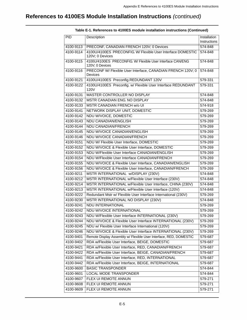
Appendix E References to 4100ES Module Installation Instructions
4100-9113 PRECONF, CANADIAN FRENCH 120V; 0 Devices 574-848
4100-9114 4100U/4100ES PRECONFIG. W/ Flexible User Interface DOMESTIC 120V; 0 Devices
574-848
4100-9115 4100U/4100ES PRECONFIG. W/ Flexible User Interface CAN/ENG 120V; 0 Devices
574-848
4100-9116 PRECONF W/ Flexible User Interface, CANADIAN FRENCH 120V; 0 Devices
574-848
4100-9121 4100U/4100ES Preconfig.REDUNDANT 120V 579-331
4100-9122 4100U/4100ES Preconfig. w/ Flexible User Interface REDUNDANT 120V
579-331
4100-9131 MASTER CONTROLLER NO DISPLAY 574-848
4100-9132 MSTR CANADIAN ENG. NO DISPLAY 574-848
4100-9133 MSTR CANADIAN FRENCH w/o UI 574-918
4100-9141 NETWORK DISPLAY UNIT, DOMESTIC 579-269
4100-9142 NDU W/VOICE, DOMESTIC 579-269
4100-9143 NDU CANADIAN/ENGLISH 579-269
4100-9144 NDU CANADIAN/FRENCH 579-269
4100-9145 NDU W/VOICE CANADIAN/ENGLISH 579-269
4100-9146 NDU W/VOICE CANADIAN/FRENCH 579-269
4100-9151 NDU W/ Flexible User Interface, DOMESTIC 579-269
4100-9152 NDU W/VOICE & Flexible User Interface, DOMESTIC 579-269
4100-9153 NDU W/Flexible User Interface CANADIAN/ENGLISH 579-269
4100-9154 NDU W/Flexible User Interface CANADIAN/FRENCH 579-269
4100-9155 NDU W/VOICE & Flexible User Interface, CANADIAN/ENGLISH 579-269
4100-9156 NDU W/VOICE & Flexible User Interface, CANADIAN/FRENCH 579-269
4100-9211 MSTR INTERNATIONAL w/DISPLAY (230V) 574-848
4100-9212 MSTR INTERNATIONAL w/Flexible User Interface (230V) 574-848
4100-9214 MSTR INTERNATIONAL w/Flexible User Interface, CHINA (230V) 574-848
4100-9213 MSTR INTERNATIONAL w/Flexible User Interface (120V) 574-848
4100-9222 Redundant Mstr w/ Flexible User Interface International (230V) 579-269
4100-9230 MSTR INTERNATIONAL NO DISPLAY (230V) 574-848
4100-9241 NDU INTERNATIONAL 579-269
4100-9242 NDU W/VOICE INTERNATIONAL 579-269
4100-9243 NDU W/Flexible User Interface INTERNATIONAL (230V) 579-269
4100-9244 NDU W/VOICE & Flexible User Interface INTERNATIONAL (230V) 579-269
4100-9245 NDU w/ Flexible User Interface International (120V) 579-269
4100-9246 NDU W/VOICE & Flexible User Interface INTERNATIONAL (230V) 579-269
4100-9401 Remote Display Assembly w/ Flexible User Interface, RED, DOMESTIC 579-687
4100-9402 RDA w/Flexible User Interface, BEIGE, DOMESTIC 579-687
4100-9421 RDA w/Flexible User Interface, RED, CANADIAN/FRENCH 579-687
4100-9422 RDA w/Flexible User Interface, BEIGE, CANADIAN/FRENCH 579-687
4100-9441 RDA w/Flexible User Interface, RED, INTERNATIONAL 579-687
4100-9442 RDA w/Flexible User Interface, BEIGE, INTERNATIONAL 579-687
4100-9600 BASIC TRANSPONDER 574-844
4100-9601 LOCAL MODE TRANSPONDER 574-844
4100-9607 FLEX UI REMOTE ANNUN 579-271
4100-9608 FLEX UI REMOTE ANNUN 579-271
4100-9609 FLEX UI REMOTE ANNUN 579-271
Table E-1. References to 4100ES module installation instructions (Continued)
PID Description Installation Instructions
References to 4100ES Module Installation Instructions (continued)
E-5
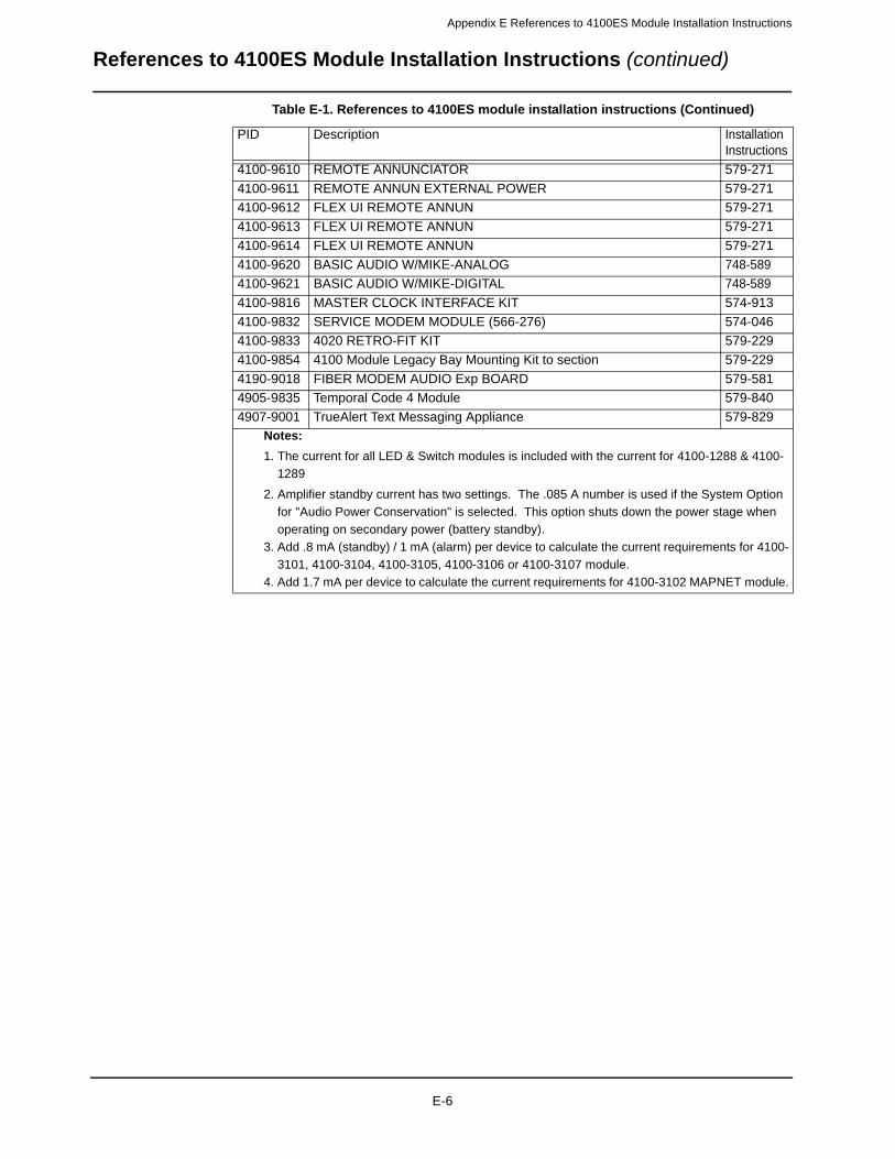
Appendix E References to 4100ES Module Installation Instructions
4100-9610 REMOTE ANNUNCIATOR 579-271
4100-9611 REMOTE ANNUN EXTERNAL POWER 579-271
4100-9612 FLEX UI REMOTE ANNUN 579-271
4100-9613 FLEX UI REMOTE ANNUN 579-271
4100-9614 FLEX UI REMOTE ANNUN 579-271
4100-9620 BASIC AUDIO W/MIKE-ANALOG 748-589
4100-9621 BASIC AUDIO W/MIKE-DIGITAL 748-589
4100-9816 MASTER CLOCK INTERFACE KIT 574-913
4100-9832 SERVICE MODEM MODULE (566-276) 574-046
4100-9833 4020 RETRO-FIT KIT 579-229
4100-9854 4100 Module Legacy Bay Mounting Kit to section 579-229
4190-9018 FIBER MODEM AUDIO Exp BOARD 579-581
4905-9835 Temporal Code 4 Module 579-840
4907-9001 TrueAlert Text Messaging Appliance 579-829
Notes:
1. The current for all LED & Switch modules is included with the current for 4100-1288 & 4100-
1289
2. Amplifier standby current has two settings. The .085 A number is used if the System Option
for "Audio Power Conservation" is selected. This option shuts down the power stage when
operating on secondary power (battery standby).
3. Add .8 mA (standby) / 1 mA (alarm) per device to calculate the current requirements for 4100-
3101, 4100-3104, 4100-3105, 4100-3106 or 4100-3107 module.
4. Add 1.7 mA per device to calculate the current requirements for 4100-3102 MAPNET module.
Table E-1. References to 4100ES module installation instructions (Continued)
PID Description Installation Instructions
References to 4100ES Module Installation Instructions (continued)
E-6
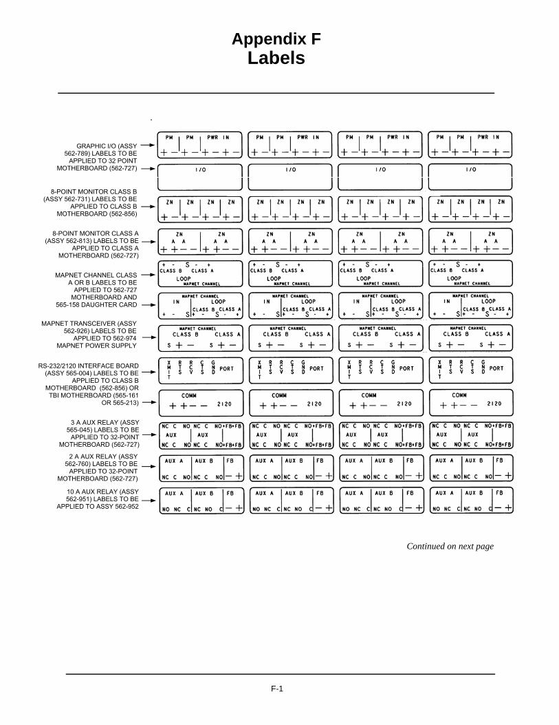
Appendix FLabels
.
Continued on next page
F-1
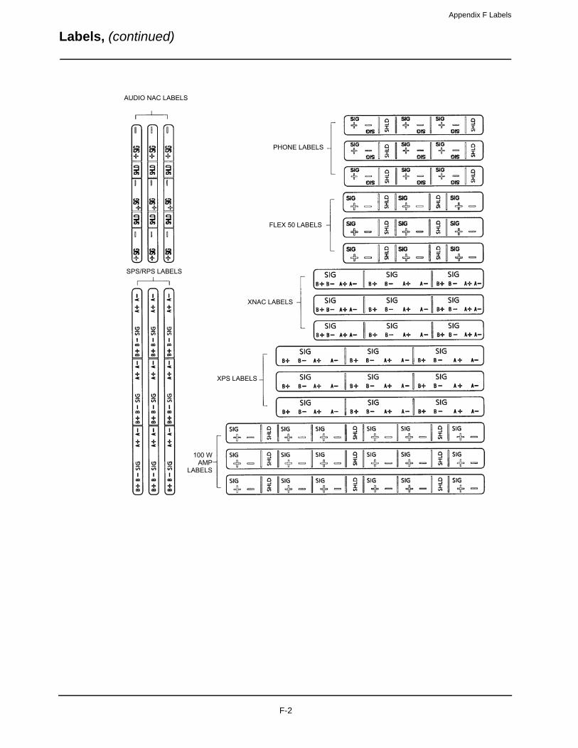
Appendix F Labels
Labels, (continued)
F-2

Appendix G
Earth Fault Diagnostics
Overview This appendix contains instructions on how to use the Earth Fault Search feature of the 4100ES diagnostics menus. The minimum Earth Fault detection level for the 4100ES is 10k ohms for all circuits.
Earth Fault Search is a diagnostic search of external field wiring that assists in locating circuits with earth faults. An earth fault occurs when an electrical circuit is shorted to ground. Although most circuits operate with a single earth fault, multiple earth faults can disable communications. Because of this, earth faults must be located and repaired.
Earth Fault Search is conducted by the FACP. The diagnostic may be activated using either the front panel interface or the Computer Port Protocol (CPP), via a service port.
The 4100ES supports two types of Earth Fault Searches:
• Location Search. Searches all circuits at a location, such as a transponder or the main panel. For the purposes of Earth Fault Searching,
- A location is composed of a group of slaves connected to each other via 4100 Comm (local RUI).
- The main panel is defined as all slaves local to the Master CPU.- A transponder denotes all slaves associated with a single Transponder Interface Card
(TIC)/Local Mode TIC slave.
• IDNet Channel Search. Selectively enables channel isolators and repeaters to detect which segment of the channel wiring has a fault.
- Earth faults are detected by one of the following:- A single designated power supply at a location. The power supply that detects the fault
is designated via a jumper setting on the power supply slave. For any given location, only one power supply should detect earth faults.
- Each 4009 IDNet NAC Extender on an IDNet channel.
G-1

Appendix G Earth Fault Diagnostics
General Guidelines
General Guidelines
Review the guidelines below before initiating an Earth Fault Search.
• The Detect Earth Fault jumper must be installed at each SPS, RPS, TPS, IPS, or 4009T for earth fault detection to occur.
• Only one power supply per location is configured to detect earth faults.
• For more reliable earth fault searching:
- Use a Firefighter Telephone NAC for each telephone riser connection to a transponder.- Use IDNet channel isolators to isolate channel faults to a specific segment of channel
wiring.- Set IDNet channel isolator addresses to the lowest IDNet device addresses, increasing
with communication distance from the IDNet card.
• If an earth fault is suspected on the IDNet channel with multiple isolators, start an IDNet Channel Search before doing a Location Search. If the Location Search is done first, it may not yield the correct location (this is a by-product of the extended amount of time required for the IDNet channel to initialize during a Location Search). Note: The 4009 IDNet NAC Extender has a common ground fault trouble that reports to the panel without running the Earth Fault Search.
• Earth Fault Search detects only one fault at a time. Multiple faults require fixing the first fault and then repeating the search.
• The FACP suspends normal operation for the duration of the Earth Fault Search.
• Location Earth Fault Searches optionally allow exclusion of auxiliary power circuits from the search, so that modules connected to the 24 V auxiliary outputs can remain in operation during the search.
• The option to exclude auxiliary power circuits does not apply to IDNet devices, because the entire IDNet communication channel is isolated during each search.
• During the search, all related troubles are suppressed and a single trouble pseudo-point is activated (P438).
• At the completion of the search, all slaves are restarted and normal panel operation resumes.
• Earth Fault Search is only supported by new 4100ES modules. 4100 Legacy (slot format) modules are not supported, with the following exceptions:
- MAPNET channel isolation during location search- IPS for earth fault detection (not recommended). The Earth Fault Search may fail
because the isolation circuits of some 4100ES slaves (such as the 4100ES telephone slave) do not support IPS.
IMPORTANT: The fire panel cannot provide fire protection during an Earth Fault Search.
G-2

Appendix G Earth Fault Diagnostics
Earth Fault Searching from the Front Panel
Overview This section describes how to conduct an Earth Fault Search, from selecting the appropriate access code to correcting the fault.
Access Level Selection
The panel must be at the appropriate access level (1, 2, 3, or 4) in order to run diagnostics. To get to the correct access level,
1. Press the Menu button. The following message comes up (press the Next or Previous but-tons, if necessary, to display it):
2. Press the Enter button. Now you are prompted to log in or log out.
3. Press the "1" key on the numeric keypad to log in, so that the passcode prompt comes up.
4. Enter the passcode and press the Enter button. ACCESS GRANTED displays briefly on the LCD, and then the display goes back to:
You can now open the diagnostic menu as described in the next topic.
Starting the Earth Fault Search
To start an Earth Fault Search,
1. If necessary, press the Menu button to access the menus.
2. Press the Previous or Next buttons until the diagnostic functions option appears:
3. Press the Enter button. Then press Next or Previous buttons until the Earth Fault Search option appears:
Continued on next page
Press <NEXT> or <PREVIOUS> to scroll Change Access Level?
1=Login 2=LogoutCURRENT ACCESS LEVEL = x
Enter a Passcode followed by <ENTER>
1=Login 2=LogoutCURRENT ACCESS LEVEL = y
Press <NEXT> or <PREVIOUS> to scrollDiagnostic Functions?
Press <NEXT> or <PREVIOUS> to scrollEarth Fault Search?
G-3

Appendix G Earth Fault Diagnostics
Earth Fault Searching from the Front Panel (continued)
Starting the Earth Fault Search
4. Press the Enter button. The following options become available when you press the Next and Previous buttons:
The search types are described below. When you have determined what kind of search to initiate, display its option (one of the three shown above) and press the Enter button. Each option has its own topic, below.
Search Option A: Select Location
• If you select the Location Search menu item, a list of cards to search becomes available. Use the Next and Previous buttons to scroll through the list.
• If you find a card that you suspect is connected to a circuit with an earth ground, press the Enter button when that circuit is shown.
• Before you can start the search, the Aux Power Select option comes up.
• The number you select, 1 or 2, determines whether the auxiliary power circuit on the selected board is searched for earth grounds. If you exclude the auxiliary power circuit from the search, the circuit will continue to operate normally.
• Press 1 (or just press the Enter button) to exclude the card's auxiliary power circuits from the search, or press 2 to remove auxiliary power circuits from normal operation and search them for earth grounds.
• Now you are prompted to start the search. When the location you want to search is shown and "Press <ENTER> to start search" displays, the search is ready to start. A sample is shown below.
Note: The FACP suspends normal operation for the duration of the search.
• Press the Enter button to start the search.
• As the search progresses, watch the display for an indication of how much of the search has been completed. The search can be aborted at any time if you press the Clear button.
• Skip ahead to the "Completing the Search" topic.
Press <NEXT> or <PREVIOUS> to scrollLocation Search
Press <NEXT> or <PREVIOUS> to scrollIDNet Channel Search
Press <NEXT> or <PREVIOUS> to scrollLast Search Result
1=Exclude 2=IncludeExclude AUXPWR circuits from search?
CARD 1, SYSTEM POWER SUPPLYPress <ENTER> to start search
Earth Search In-Progress, Please Wait...
Earth Search In-Progress, Please Wait... 40%
G-4

Appendix G Earth Fault Diagnostics
Earth Fault Searching from the Front Panel (continued)
Search Option B: Select Channel
• If you select the IDNet Channel Search menu item, a list of IDNet channels to search becomes available. Use the Next and Previous buttons to scroll through the list. When the IDNet channel you want to search is shown and "Press <ENTER> to start search" displays, the search is ready to start. A sample screen is shown below.
Note: The FACP suspends normal operation for the duration of the search.
• Press the Enter button to start the search.
• As the search progresses, watch the display for an indication of how much of the search has been completed. The search can be aborted at any time if you press the Clear button.
Skip ahead to the "Completing the Search" topic.
Search Option C: Last Search Result
This option simply displays the last Earth Fault Search result. If there has been no search since the last system startup, or if the last search was aborted, the panel displays "RESULT NOT AVAILABLE."
Completing the Search
When a Location or IDNet Channel Search completes, all of the following occurs:
• All slaves automatically reset.
• The FACP turns off the Earth Fault Search trouble pseudo-point.
• The panel displays the specific fault information.
The panel can only return one Earth Fault Search result at a time. If another fault exists, it can only be found via diagnostics after the first fault is cleared. Faults will continue to appear, one by one, until each one has been found and corrected.
IMPORTANT: Once you have been directed to an earth ground fault and corrected it, it is recommended that you restart the system (warm- or cold-start).
Continue to the next topic for a list of search results and their required actions.
IDNET CHANNEL M12Press <ENTER> to select for search
Earth Search In-Progress, Please Wait...
Earth Search In-Progress, Please Wait... 40%
G-5
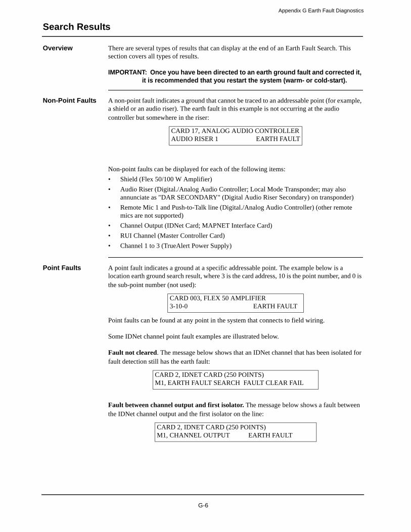
Appendix G Earth Fault Diagnostics
Search Results
Overview There are several types of results that can display at the end of an Earth Fault Search. This section covers all types of results.
IMPORTANT: Once you have been directed to an earth ground fault and corrected it, it is recommended that you restart the system (warm- or cold-start).
Non-Point Faults A non-point fault indicates a ground that cannot be traced to an addressable point (for example, a shield or an audio riser). The earth fault in this example is not occurring at the audio controller but somewhere in the riser:
Non-point faults can be displayed for each of the following items:
• Shield (Flex 50/100 W Amplifier)
• Audio Riser (Digital./Analog Audio Controller; Local Mode Transponder; may also annunciate as "DAR SECONDARY" (Digital Audio Riser Secondary) on transponder)
• Remote Mic 1 and Push-to-Talk line (Digital./Analog Audio Controller) (other remote mics are not supported)
• Channel Output (IDNet Card; MAPNET Interface Card)
• RUI Channel (Master Controller Card)
• Channel 1 to 3 (TrueAlert Power Supply)
Point Faults A point fault indicates a ground at a specific addressable point. The example below is a location earth ground search result, where 3 is the card address, 10 is the point number, and 0 is the sub-point number (not used):
Point faults can be found at any point in the system that connects to field wiring.
Some IDNet channel point fault examples are illustrated below.
Fault not cleared. The message below shows that an IDNet channel that has been isolated for fault detection still has the earth fault:
Fault between channel output and first isolator. The message below shows a fault between the IDNet channel output and the first isolator on the line:
CARD 17, ANALOG AUDIO CONTROLLERAUDIO RISER 1 EARTH FAULT
CARD 003, FLEX 50 AMPLIFIER3-10-0 EARTH FAULT
CARD 2, IDNET CARD (250 POINTS)M1, EARTH FAULT SEARCH FAULT CLEAR FAIL
CARD 2, IDNET CARD (250 POINTS)M1, CHANNEL OUTPUT EARTH FAULT
G-6
Appendix G Earth Fault Diagnostics
Search Results (continued)
Point Faults 4009 IDNet NAC Extender/TrueAlert Addressable Controller faults. The message below shows a fault detected on the 4009 IDNet NAC Extender before the repeater connected to that circuit is turned on:
Conversely, the following example shows a fault detected after the repeater connected to that circuit is turned on:
IDNet isolator fault. The message below shows a fault detected after the IDNet isolator was turned on:
Fault Not Found If the message in the lower right corner of the LCD reads FAULT NOT FOUND (for a Location Earth Fault Search) or FAULT CLEAR FAIL (for an IDNet Channel Earth Fault Search), it means the search could not locate the fault, but it acknowledges that a fault exists.
There are three main possibilities behind this message:
• There are one or more internal wiring earth(s) in the system.
• There are system defects (hardware or software, such as a failed isolation circuit).
• An intermittent earth exists in the system (it occurs inconsistently and is therefore difficult to track via diagnostics).
• The cable to the service port may be grounded due to the remote PC's 3-prong plug. Use a non-grounded plug adapter to the remote PC to get rid of the earth ground.
• The fault is on an auxiliary output that was excluded from the search.
The problem may have to be found manually and then corrected in some of the above scenarios.
No Fault If the message in the lower right corner of the LCD reads NO FAULT, it means the IDNet channel search could not locate any earth faults on that channel.
Result Not Available
If the message in the lower right corner of the LCD reads RESULT NOT AVAILABLE, it means there is no result to view. This message comes up only when you have selected "Last Search Result" on the menu.
CARD 2, IDNET CARD (250 POINTS)M1-18, 4009A NAC EARTH FAULT
CARD 2, IDNET CARD (250 POINTS)M1-18, 4009A REPEATER EARTH FAULT
CARD 2, IDNET CARD (250 POINTS)M1-3, IDNET ISOLATOR EARTH FAULT
G-7
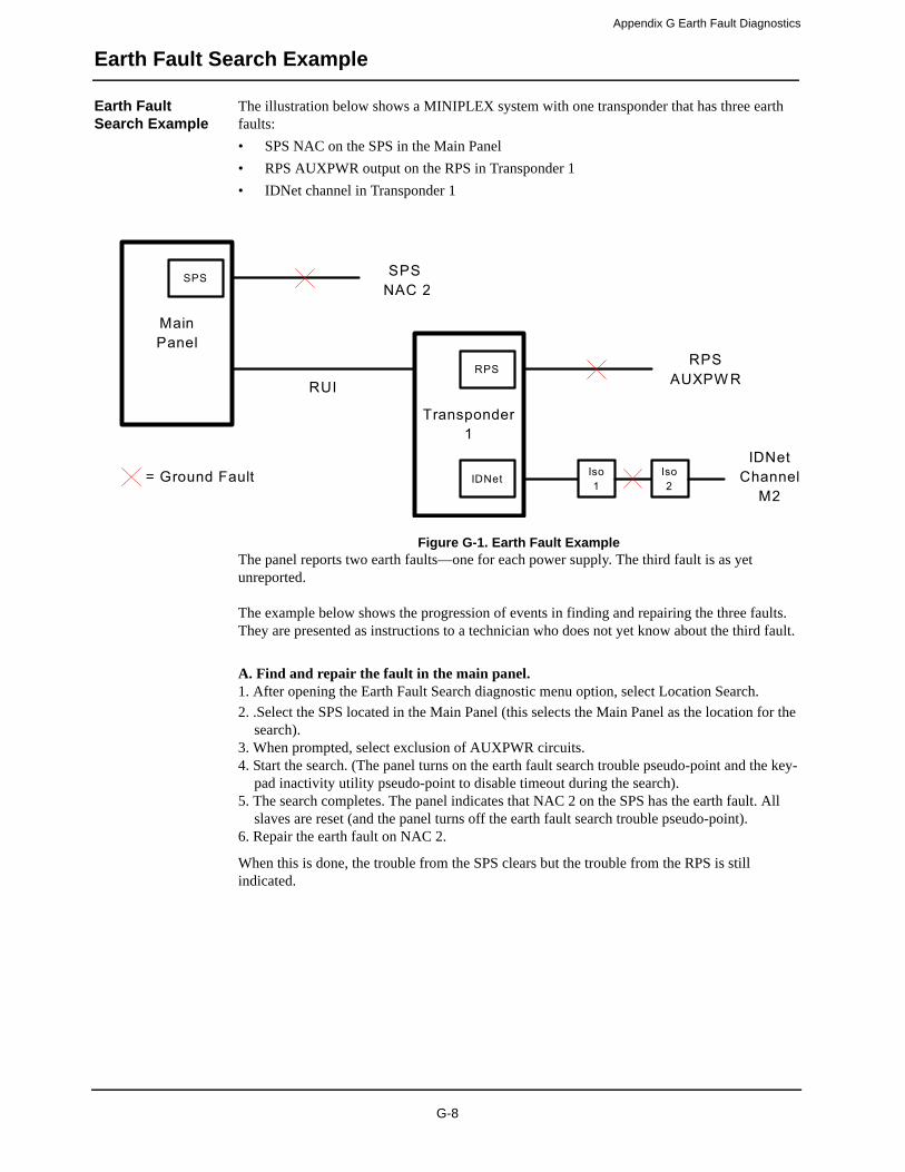
Appendix G Earth Fault Diagnostics
Earth Fault Search Example
Earth Fault Search Example
The illustration below shows a MINIPLEX system with one transponder that has three earth faults:
• SPS NAC on the SPS in the Main Panel
• RPS AUXPWR output on the RPS in Transponder 1
• IDNet channel in Transponder 1
Figure G-1. Earth Fault Example
The panel reports two earth faults—one for each power supply. The third fault is as yet unreported.
The example below shows the progression of events in finding and repairing the three faults. They are presented as instructions to a technician who does not yet know about the third fault.
A. Find and repair the fault in the main panel.1. After opening the Earth Fault Search diagnostic menu option, select Location Search.
2. .Select the SPS located in the Main Panel (this selects the Main Panel as the location for the search).
3. When prompted, select exclusion of AUXPWR circuits.4. Start the search. (The panel turns on the earth fault search trouble pseudo-point and the key-
pad inactivity utility pseudo-point to disable timeout during the search).5. The search completes. The panel indicates that NAC 2 on the SPS has the earth fault. All
slaves are reset (and the panel turns off the earth fault search trouble pseudo-point).6. Repair the earth fault on NAC 2.
When this is done, the trouble from the SPS clears but the trouble from the RPS is still indicated.
G-8

Appendix G Earth Fault Diagnostics
Earth Fault Search Example (continued)
Earth Fault Search Example
B. Find and repair the indicated fault on Transponder 1. 1. Select Location Search.
2. Select the RPS located in Transponder 1 (this selects Transponder 1 as the location for the search).
3. When prompted, select exclusion of AUXPWR circuits.4. Start the search. (The panel turns on the earth fault search trouble pseudo-point and the key-
pad inactivity utility pseudo-point to disable timeout during the search).5. The search completes. The panel indicates FAULT NOT FOUND because the fault is on the
excluded AUXPWR circuit. All slaves in Transponder 1 are reset (and the panel turns off the earth fault search trouble pseudo-point).
6. Repeat the search but include the AUXPWR circuit this time.7. The search completes. The panel indicates a fault on the AUXPWR point on the RPS. All
slaves in Transponder 1 are reset (and the panel turns off the earth fault search trouble pseudo-point).
8. Repair the earth fault on AUXPWR.Even though you have fixed the fault, the trouble from the RPS is still not clearing. Remember that the only two faults you could see at first were from the SPS and RPS. It is time to find and clear the next fault.
C. Find and repair the next indicated fault on Transponder 1. 1. Select Location Search.
2. Select the RPS located in Transponder 1.3. When prompted, select exclusion of AUXPWR circuits.4. .Start the search.5. The search completes. The panel indicates a fault on IDNet Channel M2.6. Start another search, this time an IDNet Channel Search on Channel M2.7. When prompted, select exclusion of AUXPWR circuits.8. The search completes. The panel indicates a fault on the IDNet channel between isolators 1
and 2.9. Repair the earth fault. The trouble from the RPS is cleared.
G-9


Appendix HSpecial Application NAC-Compatible Notification
Appliances and Accessories
Table H-1. Special Application NAC-Compatible Notification Appliances and Accessories
P/N DESCRIPTION
4904-9168 V/O 15CD RED FREE-RUN TNA
4904-9171 V/O 15CD WHITE FREE-RUN TNA
4904-9176 V/O 24VDC 15CD RED VER F/S
4904-9177 V/O 24VDC 15CD WHT VER F/S
4904-9178 V/O 24VDC 15CD RED HORIZ F/S
4904-9183 V/O 24VDC 15CD RED CEIL F/S
4904-9331 V/O 15CD RED SYNC TNA
4904-9342 V/O 15CD WHITE SYNC TNA
4904-9345 V/O 24VDC 15CD WHT PLAIN F/S
4904-9174 V/O 24VDC 30CD RED VER F/S
4904-9180 V/O 24VDC 30CD RED HORIZ F/S
4904-9184 V/O 24VDC 30CD RED CEIL F/S
4904-9346 V/O 24VDC 30CD WHT PLAIN F/S
4904-9169 V/O 75CD RED FREE-RUN TNA
4904-9172 V/O 75CD WHITE FREE-RUN TNA
4904-9332 V/O 75CD RED SYNC TNA
4904-9343 V/O 75CD WHITE SYNC TNA
4904-9170 V/O 110CD RED FREE-RUN TNA
4904-9173 V/O 110CD WHITE FREE-RUN TNA
4904-9175 V/O 24VDC 110CD RED VER F/S
4904-9181 V/O 24VDC 110CD WHT VER F/S
4904-9182 V/O 24VDC 110CD RED HOR F/S
4904-9185 V/O 24VDC 110CD RED CEIL F/S
4904-9333 V/O 110CD RED SYNC TNA
4904-9344 V/O 110CD WHITE SYNC TNA
4906-9101 V/O 15/30/75/110cd W/M RED TNA
4906-9103 V/O 15/30/75/110cd W/M WHT TNA
4906-9102 V/O 15/30/75/110cd C/M RED TNA
4906-9104 V/O 15/30/75/110cd C/M WHT TNA
4906-9105 V/O WEATHERPROOF W/M RED
4906-9106 V/O WEATHERPROOF W/M WHT
4906-9113 V/O WEATHERPROOF W/M (CAN) RED
4903-9356 S/V 15CD RED 25/70V TNA
4903-9359 S/V 15CD WHITE 25/70V TNA
4903-9150 S/V 24VDC 15CD RED HORIZ F/S
4903-9153 S/V 24VDC 15CD RED VER F/S
H-1

Appendix H Special Application NAC-Compatible
4903-9193 S/V 24VDC 15CD WHT HORIZ F/S
4903-9196 S/V15CD RND
4903-9148 S/V 24VDC 30CD RED HORIZ F/S
4903-9194 S/V 24VDC 30CD WHT HORIZ F/S
4903-9197 S/V, 30CD, RND TNA
4903-9357 S/V 75CD RED 25/70V TNA
4903-9360 S/V 75CD WHITE 25/70V TNA
4903-9358 S/V 110CD RED 25/70V TNA
4903-9361 S/V 110CD WHITE 25/70V TNA
4903-9198 S/V 110CD, RND TNA
4906-9151 S/V 15/30/75/110cd W/M RED TNA
4906-9153 S/V 15/30/75/110cd W/M WHT TNA
4906-9154 S/V 15/30/75/110cd C/M WHT TNA
4901-9820 HORN 24VDC RED TNA
4901-9822 HORN 24VDC RED
4009-9201 NAC EXTENDER 120VAC, IDNET
4009-9301 NAC EXTENDER, 240VAC, IDNET
4009-9401 4009 T/A ADDR CONTROLLER
4903-9252 A/V 24VDC 15CD RED HOR F/S
4903-9253 A/V 24VDC 30CD RED HOR F/S
4903-9254 A/V 24VDC 110CD RED HOR F/S
4903-9255 A/V 24VDC 15CD RED VER F/S
4903-9256 A/V 24VDC 110CD RED VER F/S
4903-9257 A/V 24VDC 15CD WHT HOR F/S
4903-9258 A/V 24VDC 30CD WHT HOR F/S
4903-9417 A/V 15CD RED SYNC TNA
4903-9418 A/V 75CD RED SYNC TNA
4903-9419 A/V 110CD RED SYNC TNA
4903-9425 A/V 15CD RED STD TNA
4903-9426 A/V 75CD RED STD TNA
4903-9427 A/V 110CD RED STD TNA
4903-9428 A/V 15CD WHITE SYNC TNA
4903-9429 A/V 75CD WHITE SYNC TNA
4903-9430 A/V 110CD WHITE SYNC TNA
4903-9431 A/V 15CD WHITE STD TNA
4903-9432 A/V 75CD WHITE STD TNA
Table H-1. Special Application NAC-Compatible Notification Appliances and Accessories (Continued)
P/N DESCRIPTION
Notification Appliances and Accessories
Special Application NAC-Compatible Notification Appliances and Accessories
H-2

Appendix H Special Application NAC-Compatible
4903-9433 A/V 110CD WHITE STD TNA
4906-9127 A/V 15/30/75/110cd W/M RED
4906-9129 A/V 15/30/75/110cd W/M WHT
4906-9128 A/V 15/30/75/110cd C/M RED
4906-9130 A/V 15/30/75/110cd C/M WHT
4906-9131 A/V WEATHERPROOF W/M RED
4906-9132 A/V WEATHERPROOF W/M WHT
4906-9143 A/V WEATHERPROOF W/M (CAN) RED
4906-9201 - 9204 MUTLI-CANDELA
4906-9251 - 9254 MUTLI-CANDELA
4906-9227 - 9230 MUTLI-CANDELA
4906-9105 - 9106 WEATHERPROOF
4906-9131 - 9132 WEATHERPROOF
4906-9113 - 9143 WEATHERPROOF
4905-9815 SMARTSYNC ADAPTER, TNA
4905-9938 SMARTSYNC CTL MODULE
4090-9005 SRP
4090-9006 SRP w/ENCLOSURE
Table H-1. Special Application NAC-Compatible Notification Appliances and Accessories (Continued)
P/N DESCRIPTION
Notification Appliances and Accessories
Special Application NAC-Compatible Notification Appliances and Accessories
H-3


Appendix ICooper Wheelock Appliances Compatible With 4100ES
Wheelock Protocol For Special Applications
Overview The tables in this appendix list Cooper Wheelock appliances compatible with 4100ES Wheelock protocol for special applications
Synchronizing Horn Strobes
Table I-1. Synchronizing Horn Strobes
Appliance Description
AS-241575W AS Series Horn Strobe. 24VDC, 15/75Cd, Wall Mount
AS-24MCW AS Series Horn Strobe. 24VDC, Multi-Cd, Wall Mount
AS-24MCC AS Series Horn Strobe. 24VDC, Multi-Cd, Ceiling Mount
AS-24MCWH AS Series Horn Strobe. 24VDC, Multi-High-Cd, Wall Mount
AS-24MCCH AS Series Horn Strobe. 24VDC, Multi-High-Cd, Ceiling Mount
ASWP-2475W, ASWP-2475C AS Series WP Horn Strobe. 24VDC, 30Cd, Wall or Ceiling Mount
ASWP-24MCWH AS Series WP Horn Strobe. 24VDC, Multi-High-Cd, Wall Mount
ASWP-24MCCH AS Series WP Horn Strobe. 24VDC, Multi-High-Cd, Ceiling Mount
ASA-24MCW, ASB-24MCW AS Series Horn Strobe. 24VDC, Multi-Cd, Wall Mount. Amber/Blue
ASA-24MCC, ASB-24MCC AS Series Horn Strobe. 24VDC, Multi-Cd, Ceiling Mount. Amber/Blue
HSR HN STR, Red , 2-Wire, Wall, 12/24VDC, 3dB, 8CD, 5 Mount
HSRC HN STR, Red, 2-wire, Ceiling Mount, 12/24VDC, 3dB, 8 Cd, 5 Mount
HSRCS HN STR, Silver red, 2-wire, Ceiling Mount, 12/24VDC, 3dB, 8 Cd, 5 Mount
HSRS HN STR, Silver Red, 2-Wire, Wall, 12/24VDC, 3dB, 8CD, 5 Mount
HSW HN STR, White, 2-Wire, Wall, 12/24VDC, 3dB, 8CD, 5 Mount
HSWC HN STR, White, 2-wire, Ceiling Mount, 12/24VDC, 3dB, 8 Cd, 5 Mount
HSWCS HN STR, Silver white, 2-wire, Ceiling Mount, 12/24VDC, 3dB, 8 Cd, 5 Mount
HSWS HN STR, Silver White, 2-Wire, Wall, 12/24VDC, 3dB, 8CD, 5 Mount
HS4-241575W HS4 Series Horn Strobe. 24VDC, 15/75Cd, Wall Mount
HS4-24MCW HS4 Series Horn Strobe. 24VDC, Multi-Cd, Wall Mount
HS4-24MCWH HS4 Series Horn Strobe. 24VDC, Multi-High-Cd, Wall Mount
HS4-24MCC HS4 Series Horn Strobe. 24VDC, Multi-Cd, Ceiling Mount
NS-241575W NS Series Horn Strobe. 24VDC, 15/75Cd, Wall Mount
NS-24MCW NS Series Horn Strobe. 24VDC, Multi-Cd, Wall Mount
NS-24MCC NS Series Horn Strobe. 24VDC, Multi-Cd, Ceiling Mount
NS-24MCCH NS Series Horn Strobe. 24VDC, Multi-High-Cd, Ceiling Mount
ZNS-MCW ZNS Series Horn Strobe. 24VDC, Multi-Cd, Wall Mount
ZNS-MCWH ZNS Series Horn Strobe. 24VDC, Multi-High-Cd, Wall Mount
ZNS-24MCC ZNS Series Horn Strobe. 24VDC, Multi-Cd, Ceiling Mount
ZNS-24MCCH ZNS Series Horn Strobe. 24VDC, Multi-High-Cd, Ceiling Mount
I-1

Appendix I Cooper Wheelock Appliances Compatible With
Synchronizing strobes
Table I-2. Synchronizing strobes
Appliance Description
RSS-241575W RSS Series Strobe. 24VDC, 15/75Cd, Wall Mount
RSSP-241575W RSSP Series Strobe. 12VDC or 24VDC, 15/75Cd, Wall Mount
RSS-24MCW, RSSP-24MCW RSS/RSSP Series Strobe. 24VDC, Multi-Cd, Wall Mount
RSS-24MCWH, RSSP-24MCWH RSS/RSSP Series Strobe. 24VDC, Multi-High-Cd, Wall Mount
RSS-24MCC, RSS-24MCCR RSS Series Strobe. 24VDC, Multi-Cd, Ceiling Mount (R=Round)
RSS-24MCCH, RSS-24MCCHR RSS Series Strobe. 24VDC, Multi-High-Cd, Ceiling Mount (R=Round)
RSSR-2415W, RSSR-2415C RSS Series Strobe. 24VDC, 15Cd, Red, Wall or Ceiling Mount
RSSR-2475W, RSSR-2475C RSS Series Strobe. 24VDC, 75Cd, Red, Wall or Ceiling Mount
RSSR-24110C RSS Series Strobe. 24VDC, 110Cd, Red, Ceiling Mount
RSSA-24110W, RSSB-24110W,RSSG-24110W, RSSR-24110W
RSS Series Strobe. 24VDC, 110Cd, Wall Mount. Amber/Blue/Green/Red.
RSSA-24MCC, RSSB-24MCC,RSSG-24MCC, RSSR-24MCC
RSS Series Strobe. 24VDC, Multi-Cd, Ceiling Mount. Amber/Blue/Green/Red.
RSSA-24MCCH, RSSB-24MCCH,RSSG-24MCCH, RSSR-24MCCH
RSS Series Strobe. 24VDC, Multi-High-Cd, Ceiling Mount. Amber/Blue/Green/Red.
RSSPA-24MCC RSSP Series Strobe. 24VDC, Multi-Cd, Ceiling Mount. Amber
RSSWPA-2475W RSS Series WP Strobe. 24VDC, Wall Mount. Amber
RSSWPA-24MCCH,RSSWPB-24MCCH,RSSWPG-24MCCH,RSSWPR-24MCCH
RSS Series WP Strobe. 24VDC, Multi-High-Cd, Ceiling Mount. Amber/Blue/Green/Red.
RSSWP-2475W, RSSWP-2475C RSS Series WP Strobe. 24VDC, 30Cd, Wall or Ceiling Mount
RSSWP-24MCWH RSS Series WP Strobe. 24VDC, Multi-High-Cd, Wall Mount
RSSWP-24MCCH RSS Series WP Strobe. 24VDC, Multi-High-Cd, Ceiling Mount
STR STR, Red, 2-Wire, Wall, 12/24VDC, 12/24VDC, 8CD, 5 Mount
STRC STR, Red, 2-wire, Ceiling Mount, 12/24VDC, 8 Cd, 5 Mount
STRCS STR, Silver red, 2-wire, Ceiling Mount, 12/24VDC, 8 Cd, 5 Mount
STRS STR, Silver Red, 2-Wire, Wall, 12/24VDC, 12/24VDC, 8CD, 5 Mount
STW STR, White, 2-Wire, Wall, 12/24VDC, 12/24VDC, 8CD, 5 Mount
STWC STR, White, 2-wire, Ceiling Mount, 12/24VDC, 8 Cd, 5 Mount
STWCS STR, Silver white, 2-wire, Ceiling Mount, 12/24VDC, 8 Cd, 5 Mount
STWS STR, Silver White, 2-Wire, Wall, 12/24VDC, 12/24VDC, 8CD, 5 Mount
ZRS-MCW ZRS Series Strobe. 24VDC, Multi-Cd, Wall Mount
ZRS-MCWH ZRS Series Strobe. 24VDC, Multi-High-Cd, Wall Mount
ZRS-24MCC ZRS Series Strobe. 24VDC, Multi-Cd, Ceiling Mount
ZRS-24MCCH ZRS Series Strobe. 24VDC, Multi-High-Cd, Ceiling Mount
4100ES Wheelock Protocol For Special Applications
Compatible Appliances (continued)
I-2

Appendix I Cooper Wheelock Appliances Compatible With
Appliances with synchronizing strobes
Table I-3. Appliances with synchronizing strobes
Appliance Description
(Only Strobe portion compatible with the 4008 Wheelock Protocol for Special Applications)
AMT-241575W,AMT-241575W-NYC
AMT Series Multi-Tone Horn Strobe. 24VDC, 15/75Cd, Wall Mount
AMT-24MCW AMT Series Multi-Tone Horn Strobe. 24VDC, Multi-Cd, Wall Mount
MT-241575W MT Series MT Horn Strobe. 24VDC, 15/75Cd, Wall Mount.
MT-24MCW MT Series Multi-Tone Horn Strobe. 24VDC, Multi-Cd, Wall Mount
MTWP-2475W, MTWP-2475C MTWP Series MT Horn Strobe. 24VDC, 30Cd, Wall or Ceiling Mount
MTWP-24MCWH MTWP Series MT Horn Strobe. 24VDC, Multi-High-Cd, Wall Mount
MTWP-24MCCH MTWP Series MT Horn Strobe. 24VDC, Multi-High-Cd, Ceiling Mount
MTWPA-2475W, MTWPB-2475WMTWPG-2475W, MTWPR-2475W
MTWP Series Multi-Tone Horn Strobe. 24VDC, Wall Mount. Amber/Blue/Green/Red
MTA-24MCCH, MTB-24MCCH,MTG-24MCCH, MTR-24MCCH
MT Series Multi-Tone Horn Strobe. 24VDC, Multi-High-Cd, Wall Mount. Amber/Blue/Green/Red
MTWPA-24MCCH, MTWPB-24MCCH,MTWPG-24MCCH,MTWPR-24MCCH
MTWP Series Multi-Tone Horn Strobe. 24VDC, Multi-High-Cd, Wall Mount. Amber/Blue/Green/Red
ET70WP-2475W, ET70WP-2475C ET70WP Series Speaker Strobe. 24VDC, 30Cd, Wall or Ceiling Mount
ET70WP-24185W ET70WP Series Speaker Strobe. 24VDC, 185Cd, Wall Mount
ET70WP-24177C ET70WP Series Speaker Strobe. 24VDC, 177Cd, Ceiling Mount
ET70WPA-2475 ET70WP Series Speaker Strobe. 24VDC, Wall or Ceiling Mt. Amber
CH70-241575W CH70 Series Chime Strobe. 24VDC, 15/75Cd, Wall Mount
CH70-24MCW CH70 Series Chime Strobe. 24VDC, Multi-Cd, Wall Mount
CH90-24MCC CH90 Series Chime Strobe. 24VDC, Multi-Cd, Ceiling Mount
CH70-24MCWH CH70 Series Chime Strobe. 24VDC, Multi-High-Cd, Wall Mount
CH90-24MCCH CH90 Series Chime Strobe. 24VDC, Multi-High-Cd, Ceiling Mount
E50-241575W E50 Series Speaker Strobe. 24VDC, 15/75Cd, Wall Mount
E50-24MCW E50 Series Speaker Strobe. 24VDC, Multi-Cd, Wall Mount
E50-24MCWH E50 Series Speaker Strobe. 24VDC, Multi-High-Cd, Wall Mount
E50A-24MCC, E50B-24MCC E50 Series Speaker Strobe. 24VDC, Multi-Cd, Ceiling Mt. Amber/Blue
E60-24MCW E60 Series Speaker Strobe. 24VDC, Multi-Cd, Wall Mount
E60-24MCWH E60 Series Speaker Strobe. 24VDC, Multi-High-Cd, Wall Mount
E60-24MCC E60 Series Speaker Strobe. 24VDC, Multi-Cd, Ceiling Mount
E60-24MCCH E60 Series Speaker Strobe. 24VDC, Multi-High-Cd, Ceiling Mount
E70-241575W E70 Series Speaker Strobe. 24VDC, 15/75Cd, Wall Mount
E70-24MCW E70 Series Speaker Strobe. 24VDC, Multi-Cd, Wall Mount
E70-24MCWH E70 Series Speaker Strobe. 24VDC, Multi-High-Cd, Wall Mount
E70-24MCC, E90-24MCC E70/E90 Series Speaker Strobe. 24VDC, Multi-Cd, Ceiling Mount
E90-24MCCH E90 Series Speaker Strobe. 24VDC, Multi-High-Cd, Ceiling Mount
4100ES Wheelock Protocol For Special Applications
Compatible Appliances (continued)
I-3

Appendix I Cooper Wheelock Appliances Compatible With
Synchronizing horns
E60A-24MCC, E70A-24MCC,E70B-24MCC, E90A-24MCC, E90B-24MCC
E60/E70/E90 Series Speaker Strobe. 24VDC, Multi-Cd, Ceiling Mount. Amber/Blue
ET70-241575W, ET90-241575W ET70/ET90 Series Speaker Strobe. 24VDC, 15/75Cd, Wall Mount
ET70-24MCW ET70 Series Speaker Strobe. 24VDC, Multi-Cd, Wall Mount
ET70-24MCWH ET70 Series Speaker Strobe. 24VDC, Multi-High-Cd, Wall Mount
ET70-24MCC, ET90-24MCC ET70/ET90 Series Speaker Strobe. 24VDC, Multi-Cd, Ceiling Mount
ET70WPG-2475, ET70WPB-2475WET70WPG-2475W, ET70WPR-2475W
ET70WP Series Speaker Strobe. 24VDC, Wall or Ceiling Mt. Green, Blue, Red
ET90-24MCCH ET90 Series Speaker Strobe. 24VDC, Multi-High-Cd, Ceiling Mount
ET80-241575W ET80 Series Speaker Strobe. 24VDC, 15/75Cd, Wall Mount
ET80-24MCW ET80 Series Speaker Strobe. 24VDC, Multi-Cd, Wall Mount
ET80-24MCWH ET80 Series Speaker Strobe. 24VDC, Multi-High-Cd, Wall Mount
S8-24MCC S8 Series Speaker Strobe. 24VDC, Multi-Cd, Ceiling Mount
S8-24MCCH S8 Series Speaker Strobe. 24VDC, Multi-High-Cd, Ceiling Mount
SA-S70-24MCW SA-S70 Series Amp-Speaker Strobe. 24VDC, Multi-Cd, Wall Mount
SA-S90-24MCC SA-S90 Series Amp-Speaker Strobe. 24VDC, Multi-Cd, Ceiling Mount
Table I-3. Appliances with synchronizing strobes (Continued)
Appliance Description
Table I-4. Synchronizing horns
Appliance Description
AH-24 AH Series Horn. 24VDC
AH-24WP AH Series Weatherproof Horn. 12VDC or 24VDC
HS-24 HS Series Horn. 24VDC
HNR Horn, Red, 2-Wire, Wall, 12/24VDC, 3dB, 5 Mount
HNRC Horn, Red, 2-wire, Ceiling Mount, 12/24V, 3dB, 5 Mount
HNRCS Horn, Silver red, 2-wire, Ceiling Mount, 12/24V, 3dB, 5 Mount
HNRS Horn, Silver Red, 2-Wire, Wall, 12/24VDC, 3dB, 5 Mount
HNW Horn, White, 2-Wire, Wall, 12/24VDC, 3dB, 5 Mount
HNWC Horn, White, 2-wire, Ceiling Mount, 12/24VDC, 3dB, 5 Mount
HNWCS Horn, Silver white, 2-wire, Ceiling Mount, 12/24VDC, 3dB, 5 Mount
HNWS Horn, Silver White, 2-Wire, Wall, 12/24VDC, 3dB, 5 Mount
MIZ-24S MIZ Series Horn. 24VDC
NH-12/24, NH-12/24R NH Series Horn. 12/24VDC (R=Round)
ZNH ZNH Series Horn. 12/24VDC
4100ES Wheelock Protocol For Special Applications
Compatible Appliances (continued)
I-4
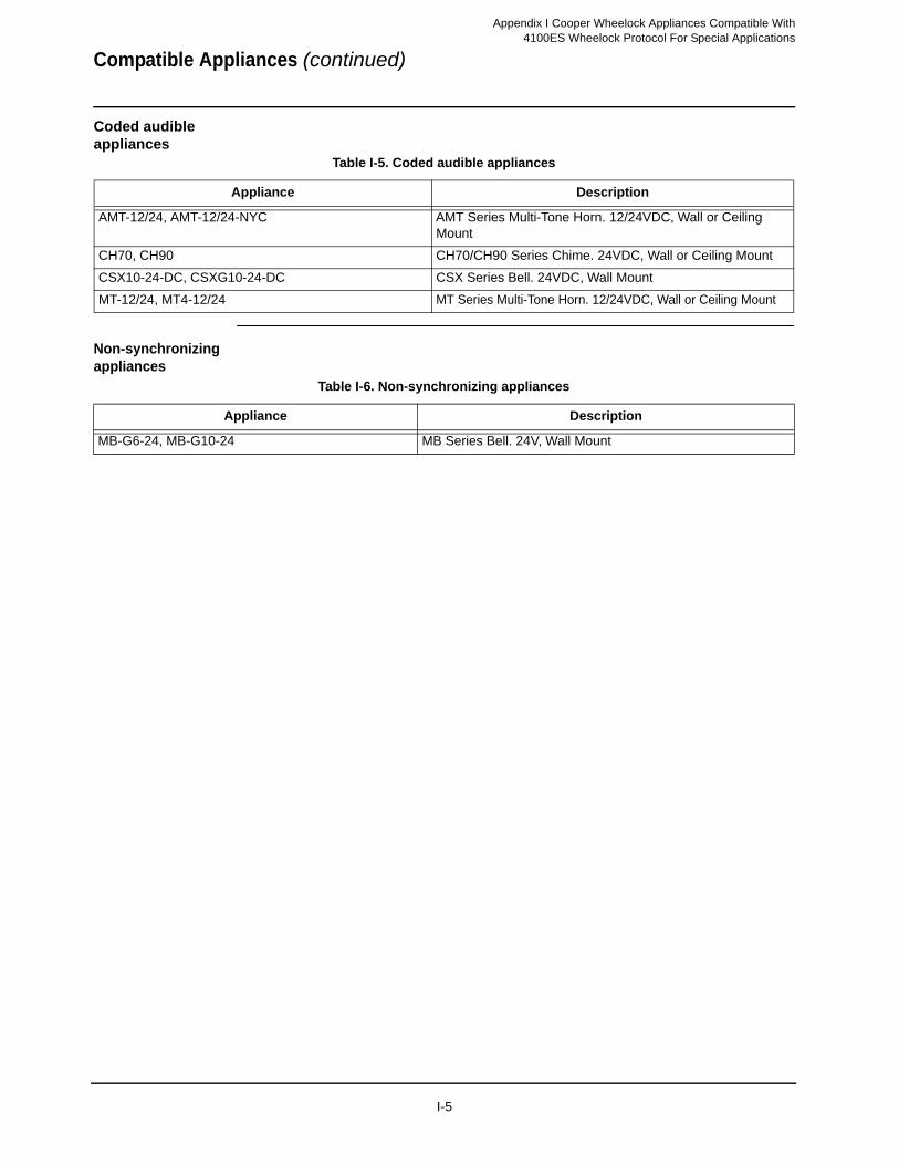
Appendix I Cooper Wheelock Appliances Compatible With
Coded audible appliances
Non-synchronizing appliances
Table I-5. Coded audible appliances
Appliance Description
AMT-12/24, AMT-12/24-NYC AMT Series Multi-Tone Horn. 12/24VDC, Wall or Ceiling Mount
CH70, CH90 CH70/CH90 Series Chime. 24VDC, Wall or Ceiling Mount
CSX10-24-DC, CSXG10-24-DC CSX Series Bell. 24VDC, Wall Mount
MT-12/24, MT4-12/24 MT Series Multi-Tone Horn. 12/24VDC, Wall or Ceiling Mount
Table I-6. Non-synchronizing appliances
Appliance Description
MB-G6-24, MB-G10-24 MB Series Bell. 24V, Wall Mount
4100ES Wheelock Protocol For Special Applications
Compatible Appliances (continued)
I-5


©
5
R
2006-201
74-84
ev. A
8
D
1 SimplexGrinnell LP. Specifications and other information were current as of publication and are subject to change without notice.