42-frank tozlu qdx4, a mechanical drive train solution for high-powered grinding mills
TRANSCRIPT

7/25/2019 42-Frank Tozlu QdX4, A Mechanical Drive Train Solution for High-Powered Grinding Mills
http://slidepdf.com/reader/full/42-frank-tozlu-qdx4-a-mechanical-drive-train-solution-for-high-powered-grinding 1/18
QdX4TM
, A Mechanical Drive Train Solution
for High-Powered Grinding Mills(CMD, Ferry-Capitain and Metso)
Fabrice Lessard 1, Michel Pasquier 2, Fabrice Wavelet3, Brady McNaughton4, Frank J. Tozlu5
1,2CMD
539 Avenue du Cateau
59400 Cambrai
France
3 Ferry-Capitain
Usine de Bussy
Vecqueville – BP33
52301 JoinvilleFrance
4,5 Metso Minerals Industries
2715 Pleasant Valley Road
York, PA
USA
(Corresponding Author: [email protected])
7/25/2019 42-Frank Tozlu QdX4, A Mechanical Drive Train Solution for High-Powered Grinding Mills
http://slidepdf.com/reader/full/42-frank-tozlu-qdx4-a-mechanical-drive-train-solution-for-high-powered-grinding 2/18
1 | P a g e
QdX4TM
A Mechanical Drive Train Solution
for High-Powered Grinding Mills
(CMD, Ferry-Capitain and Metso )
ABSTRACT
This paper introduces the QdX4TM, a mechanical drive train solution for high power grinding
mills. This specific system uses an innovative torque sharing setup to evenly distribute drive power through two pinions, effectively allowing four helical pinions to be mated to a single girth gear.
Discussion will focus on the efforts to date including, development, testing and details on lubrication,
installation, alignment and maintenance of the system.
KEYWORDS
QdX4TM, High Powered Grinding Mill, Mechanical Drive, Autogenous Grinding Mill (AG), Semi-
Autogenous Grinding Mill (SAG), Torque Sharing, Torque Splitting, Mechanical Power Sharing, Multiple
Pinion Drive, Gearless Mill Drive (GMD)
INTRODUCTION
The optimum selection of drives for AG/SAG mills is important for both the economics of the
project and the successful operation of the plant. Gear manufacturers must adjust their capabilities as
larger grinding mills become available. This paper introduces the QdX4TM, a mechanical drive train
solution for high power grinding mills. In order to produce a mechanical means of transmitting 12-28
megawatts (MW), a significant change must be made in overall drive architecture. Just as the industry
moved to load sharing of mill power through two pinions, the move to a four pinion drive is simply anatural progression in power transmission. The remainder of this paper will focus on the architecture of
the new QdX4TM system and its application to high power SAG mills.
Note: this paper focuses on the application of the QdX4TM in a SAG or AG mill installation;
however, the drive architecture can also be applied to ball mills.

7/25/2019 42-Frank Tozlu QdX4, A Mechanical Drive Train Solution for High-Powered Grinding Mills
http://slidepdf.com/reader/full/42-frank-tozlu-qdx4-a-mechanical-drive-train-solution-for-high-powered-grinding 3/18
2 | P a g e
AG AND SAG MILL SIZE / POWER INCREASES / SINGLE LINE PROCESSING
Global megatrends are driving the industry to larger equipment, specifically due to declining ore
grades and rising energy costs. As a result, mines need to process more ore to maintain the same product
yield, while at the same time reducing energy demand in order to stay profitable. With current dual pinion
drive architecture, the present limit of these mechanical systems is approximately 18-20 megawatt (MW),
even with the improvements to materials and manufacturing technology. For larger mills beyond these power levels, mill manufacturers are forced to consider the use of a Gearless Mill Drive (GMD). While
there are benefits to the GMD system, the requirements for the foundation design and technical expertise to
install and maintain these drives has prompted a demand from the industry for a reliable high powered mechanical solution. The mechanical solution must be robust, dependable, and cost competitive to other
high power grinding mill drive systems.
The QdX4TM solution meets these demands and provides the end user with a system that is easily
installed and maintainable with on-site personnel and mill wrights. Similarly, the QdX4TM design allows
for a wide range of installed mill powers. Figure 1 depicts recent SAG mills installed by Metso Minerals
(mill installed power versus mill diameter). The upper shaded region ranging from 18 MW to 28 MW
input power indicates installations where a dual QdX4TM
mill drive solution could be applied. The lower
tan shaded region ranging from 10 MW to 14 MW input power indicates installations where a single
QdX4TM mill drive could be applied. Lastly, the blue shaded region ranging from 14 MW to 18 MWindicates an area where dual pinion drives remain economical.
Figure 1 – QdX4TM Application Range

7/25/2019 42-Frank Tozlu QdX4, A Mechanical Drive Train Solution for High-Powered Grinding Mills
http://slidepdf.com/reader/full/42-frank-tozlu-qdx4-a-mechanical-drive-train-solution-for-high-powered-grinding 4/18
3 | P a g e
MOVING FROM DUAL PINION DRIVE TO QUAD PINION DRIVE
For practical reasons, connecting four pinions to four large motors is not conceivable. Similarly,
there is a practical limit with respect to girth gear size and power transmission. Therefore, a change is
needed in the overall drive architecture to efficiently transmit powers up to 28MW. This change is tosimply double the number of pinions mating to the helical girth gear, while keeping the typical
arrangement of a dual pinion drive. The QdX4TM
system provides this change in drive architecture, while
allowing the system to be built with components that are within current manufacturing capabilities,essentially allowing up to twice the power transmission of a conventional dual pinion drive. Going from a
two pinion to a four pinion arrangement is in fact a natural progression to increase power draw well beyond
the dual pinion capability. Figure 2 depicts the drive architecture.
Figure 2: Dual Drive to QdX4TM Drive Arrangement
Progressing from a traditional two motor/two helical pinion arrangement to a two motor/four
helical pinion arrangement requires an added function to the system: Mechanical Power Sharing. This is
a well-known concept in the industry, where a torque splitting system is integrated into the design,
allowing two pinions to be driven by a single input. This type of system is commonly used on large-sizeindustrial gearboxes with extremely high torque demands.

7/25/2019 42-Frank Tozlu QdX4, A Mechanical Drive Train Solution for High-Powered Grinding Mills
http://slidepdf.com/reader/full/42-frank-tozlu-qdx4-a-mechanical-drive-train-solution-for-high-powered-grinding 5/18
4 | P a g e
THE SOLUTION – QdX4TM
The challenge here was to produce a power sharing system which is robust, reliable, cost-effective
and which meets the demands of the mining industry. This was achieved by reducing the number of parts
to a minimum, by simplifying the kinematic chain and by making installation and maintenance operations
simpler. Components of proven reliability were selected and calculations were made throughout the entire
design using recognized standards regularly applied to mining equipment.
The QdX4TM
power sharing system, as shown in Figure 3, consists of a single helical input pinion
(dividing pinion) mated to two low speed gear wheels. The input pinion shaft has been specially designed to provide a radial degree of freedom (discussed in the following section) while maintaining optimum
contact for the gearing. The low speed gear wheels are connected to the helical pinions of the open mill
gearing. Gear mesh synchronization of the QdX4TM mill drive gear is achieved by the use of an internal
locking device on one of the low speed gear wheels. These features are critical to the concept and were
proven on the full scale, long term test bench (discussed in the “Test Bench” section).
Figure 3: QdX4TM Torque Sharing System
FOUR PINIONS AND MECHANICAL POWER SHARING
The main purpose of the mechanical power sharing is to divide the torque into two separate and
equivalent paths in order to increase the gear unit capacity without increasing the overall weight and size.The concept of mechanical load sharing is well recognized and can be translated into multiple technical
solutions. The most common types of arrangements include industrial planetary reducers, industrial pinion
stands (rolling mills) and other power splitting gearboxes.
Like in any other power sharing solution, a mechanical gear splitting system comes with its own
challenges. Understanding these challenges is essential to achieve the best performance.
An ideal gear transmission could be described by the following rules, considering power
transmission and ratio as constant: output motion (θ o) is linked to input motion (θ i) by the transmission
ratio (u). As a result, output torque (T o) is linked to the input torque (T i) by the inverse transmission ratio(u
-1):
= . =.
However, in reality, a more truthful description of gear transmission could be given as follows:
= .() =.()

7/25/2019 42-Frank Tozlu QdX4, A Mechanical Drive Train Solution for High-Powered Grinding Mills
http://slidepdf.com/reader/full/42-frank-tozlu-qdx4-a-mechanical-drive-train-solution-for-high-powered-grinding 6/18
5 | P a g e
Here, it can be seen that the transmission ratio is not a constant and could fluctuate over a period
of time due to the deviations of the actual gear system. Two types of parameters influence the kinematic
response:
- Transmission tolerances, mainly due to machining and assembly (no-load dependent parameters:e.g. pitch error, run out)
- Quasi-static behavior of loaded gears meshing kinematic (load dependent parameters)
Figure 4: Example of Cumulative Ratio Variation for Load & No-Load
The power sharing system has to deal with an over-determined mechanical challenge. As shown
previously, transmission reduction ratio of an actual gear set cannot be described as a basic constant; it istime-varying. In the case of the power sharing system, two (or more) geared pathways co-exist in the same
transmission, each one having an independent time varying ratio. This over determination means, should it
be solved mathematically, that the same physical shaft could move in two different ways. The traditional
mechanical solution to the above is to permit one additional degree of freedom to the transmission system.This is commonly achieved by giving the degree of freedom to the pinion shaft from which the power is
shared by allowing it to move either axially or radially.
Axial displacement technology relies on maintaining a constant rotation angle during translation:
over time, angular variations on each side of the split would result in axial displacements of the pinion,
thanks to the helix angle. While radial displacement technology is directly based on the fundamental
property of involute gearing; a gear set should be able to operate regardless of its center distance.
The QdX4TM drive takes advantage of the radial displacement theory. By allowing the pinion to
move in a radial direction, the QdX4TM is able to maintain contact between all mating gears, even with
angular variation. Figure 5 illustrates the mathematical approach to the QdX4TM design.
Figure 5: Theoretical Relationship Linking Radial Displacement to Kinematic Angular Variations

7/25/2019 42-Frank Tozlu QdX4, A Mechanical Drive Train Solution for High-Powered Grinding Mills
http://slidepdf.com/reader/full/42-frank-tozlu-qdx4-a-mechanical-drive-train-solution-for-high-powered-grinding 7/18
6 | P a g e
POWER SHARING ON A MILL DRIVE SYSTEM
For the QdX4TM system, exhaustive research was conducted to identify all the parameters
influencing the entire kinematic chain. These were evaluated for both the drive and the mill itself
throughout the life of the system, so that no single parameter would be ignored. Figure 6 depicts many of
the parameters considered.
Figure 6: Parameters of Variability Applied to the Whole System
Figure 7 is listing of elements which may have a direct influence on power sharing within a milldrive system, thus generating a pitch deviation at a specific frequency.
Figure 7: Example of Influencing Parameters
Physical phenomena which infuence torque
splitting systemcriteria
effect
frequency
Girth gear mouting: radial runout 0.08 x D 1.152 mm 0.0453 in 0.080 mm 0.0031 in 0.15 Hz
Girth gear mouting: axial runout 0.05 x D 0.720 mm 0.0283 in 0.006 mm 0.0002 in 0.15 Hz
Girth gear accuracy: cumulative pitch errorAGMA 10
ISO 70.101 mm 0.0040 i n 0. 101 mm 0.0040 in 0.15 Hz
LS pinion 1 accuracy: cumulative pitch errorAGMA 12
ISO 50.056 mm 0.0022 i n 0. 056 mm 0.0022 in 2.50 Hz
LS pinion 2 accuracy: cumulative pitch errorAGMA 12
ISO 50.056 mm 0.0022 i n 0. 056 mm 0.0022 in 2.50 Hz
HS wheel 1 accuracy: cumulative pitch errorAGMA 12
ISO 50.053 mm 0.0021 i n 0. 035 mm 0.0014 in 2.50 Hz
HS wheel 2 accuracy: cumulative pitch errorAGMA 12
ISO 50.053 mm 0.0021 i n 0. 035 mm 0.0014 in 2.50 Hz
HS pinion accuracy: cumulative pitch error
AGMA 12
ISO 5 0.038 mm 0.0015 i n 0. 025 mm 0.0010 in 5.72 Hz
temperature effect on main casing ΔT=10°C 0.21 mm 0.0084 in 0.21 mm 0.0084 in static
temperature effect on mill position ΔT=28°C 1.30 mm 0.0512 in 0.09 mm 0.0036 in static
mounting allowance for splitting pinion set-up 0.100 mm 0.0039 in 0.13 mm 0.0052 in static
Dynamic
effect
static
effect
valueEquivalent pitch error
on LS meshing
assembly error
kinematic error
thermal effects
mill body deformation
kinematic error
bearing/support
variance
concrete
foundation aging

7/25/2019 42-Frank Tozlu QdX4, A Mechanical Drive Train Solution for High-Powered Grinding Mills
http://slidepdf.com/reader/full/42-frank-tozlu-qdx4-a-mechanical-drive-train-solution-for-high-powered-grinding 8/18
7 | P a g e
To have the most realistic design that can be easily adapted to the mining industry, all parameters
were either based on tolerances or on operating ranges. Rather than using min, max or average numbers, a
probabilistic approach was taken and random picks were made within the allowable range using a
statistical distribution function. All parameters were later combined and applied to the theoretical model
using this method. Figure 8 depicts each physical phenomenon and its influence to pinion displacement
over a single girth gear rotation.
Figure 8: General View of All Parameters
A large number of simulations were made (>1000) using an algorithm developed specifically to
statistically determine the most probable behavior of the dividing pinion as per Monte Carlo simulation.This technique has enabled us to determine what could be the most probable operating conditions for thedividing pinion (see Figure 9). The data was later used for completing the design of the entire power transmission system.
Figure 9: Example of Radial Displacement of Dividing Pinion Over One Mill Rotation
-0.15
-0.1
-0.05
0
0.05
0.1
0.15
0 50 100 150 200 250 300 350 400
Displacement of HS pinion according to each p hysical phenomenon
Girth gear mouting: radial runout
Girth gear mouting: axial runout
Girth gear accuracy: cumulative pitch error
LS pinion 1 accuracy: cumulative pitch error
LS pinion 2 accuracy: cumulative pitch error
HS wheel 1 accuracy: cumulative pitch error
HS wheel 2 accuracy: cumulative pitch error
HS pinion accuracy: cumulative pitch error
temperature effect on main casing
temperature effect on mill position
mill rotation axe position change
mounting allowance for splitting pinion set-up
-0.5
-0.4
-0.3
-0.2
-0.1
0
0.1
0.2
0.3
0.4
0.5
0 50 100 150 200 250 300 350 400
Cumulative radial displacement of HS pinion

7/25/2019 42-Frank Tozlu QdX4, A Mechanical Drive Train Solution for High-Powered Grinding Mills
http://slidepdf.com/reader/full/42-frank-tozlu-qdx4-a-mechanical-drive-train-solution-for-high-powered-grinding 9/18
8 | P a g e
FULL SCALE TEST TO CORRELATE WITH THEORETICAL MODELS
To fully develop the QdX4TM solution, a full scale instrumented test bench was designed and
constructed to test the QdX4TM torque division system under the most severe operating conditions. Figure
10 depicts the test conditions and how they relate to a 40’ SAG mill operating at 28 MW.
Operating Conditions@ Input
(QdX4TM Pinion Stand)
Correspondence on a
40'SAG @ 28MW
Input Speed 335 rpm 100 % (15 to 150%)
Torque 350 000 Nm 100 % (0 to 120%)
Power rating 14 MW 100 % (0 to 120%)
Pitch deviation frequency 0 to 2.5Hz 0 to 2.5Hz
Pitch deviation amplitude 0 to 1.5 mm 0 to 1.0 mm
Figure 10: Test Bench Inputs
TEST BENCH
As shown in Figure 11, the test bench is driven by a VFD motor, and is composed of two QdX4TM
torque splitting sub-assemblies operating in a closed loop. Both sides are tested simultaneously. The torque
is generated by a hydraulic actuator, then maintained or adjusted as desired, to produce the required torqueof a system operating at 14 MW. Energy consumption of the VFD motor to maintain the system in rotation
equals the mechanical energy loss (roughly 100 kW).
Figure 11: QdX4TM Test Bench
Electric Motor QdX4 #1 Torque Actuator QdX4 #2
Kinematicdeviationactuators

7/25/2019 42-Frank Tozlu QdX4, A Mechanical Drive Train Solution for High-Powered Grinding Mills
http://slidepdf.com/reader/full/42-frank-tozlu-qdx4-a-mechanical-drive-train-solution-for-high-powered-grinding 10/18
9 | P a g e
TEST PROTOCOL
The test protocol was developed to simulate the effects of the pitch deviation as discussed in the
“Power Sharing on a Mill Drive System” section. It was desired to evaluate how torque was to be divided
for a combination of pitch deviation amplitudes at a frequency varying from 0 to 2.5 Hz, which were
generated by kinematic actuators. Pitch deviation of the pinion itself occurred at 5Hz. Figure 12 represents
the typical pitch deviation, as seen by the dividing pinion, under a combination of multiple effects – superposition of physical phenomena as listed in Figure 7. As a result, typical testing sequence is shown in
Figure 13.
Figure 12 – Superposition of Testing Protocol and Probabilistic Variation
Figure 13 – Typical Test Sequence
(1) low frequency sequence - 0.2Hz typical
probabilistic
pitch
error
on
SAG
mill
1 2 3 4 5 60
0.05
0.10
0.15
0.20
0.2 2.2
combined
effect
of
girth
gear
run-out,
kinematic
deviation
and
mounting
tolerance
equivalent
LS Pitch error
amplitude
Frequency
combined
effect
of
pinions
kinematic
deviation =
equivalent
LS pitch error
amplitude
frequency 0.2 Hz
0.13mm
(seq. 1) max probabilistic value
(low
frequency)
(seq.2) max probabilistic value
(medium frequency)
(seq. 3) extreme working
sequence
4 x max probabilistic value
frequency 2.2 Hz
0.08mm
frequency 0.2 Hz
0.50mm
equivalent
LS pitch error
amplitude
equivalent
LS pitch error
amplitude

7/25/2019 42-Frank Tozlu QdX4, A Mechanical Drive Train Solution for High-Powered Grinding Mills
http://slidepdf.com/reader/full/42-frank-tozlu-qdx4-a-mechanical-drive-train-solution-for-high-powered-grinding 11/18
10 | P a g e
SYSTEM RESULTS IN RESPONSE TO EXCITATIONS CAUSED BY DEVIATIONS
The ability of the dividing pinion to respond to excitation caused by deviation was analyzed both
in terms of reacting speed (latency) and in terms of displacement which would lead to the best torque
division ratio. Figure 14 shows the results obtained for three different series of tests.
Figure 14 – Test Results
Results show that the pinion displacement is in phase with the excitation and that the fluctuation
of the torque distribution ratio remains under 1%, regardless of the amplitude and the excitation frequency.
For example, the variation is less than 70kW for an installed power of 14MW. Similar results were
obtained for up to 2.5 Hz.
(seq. 1) Low frequency sequence - 0.2Hz
max probabilistic pitch error
(seq.2) Medium frequency sequence - 2.2Hz
max probabilistic pitch error
(seq. 3) Extreme working sequence
4 x sequence 1 pitch error
Equivalent LS pitch error (mm) actuated on test bench function of time
Unbalanced Power ratio (% of total amount of power) measured between transmission power paths function of time
Power Sharing Pinion radial motion (mm) measured response function of time
7/25/2019 42-Frank Tozlu QdX4, A Mechanical Drive Train Solution for High-Powered Grinding Mills
http://slidepdf.com/reader/full/42-frank-tozlu-qdx4-a-mechanical-drive-train-solution-for-high-powered-grinding 12/18
11 | P a g e
Contact Pattern
Contact pattern varies between the dividing pinion and the mating gears as the pinion auto-
compensates for the deviations. The test bench was specifically instrumented to analyze those variations.
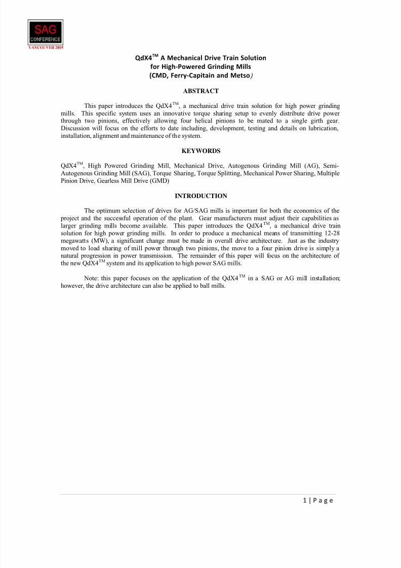
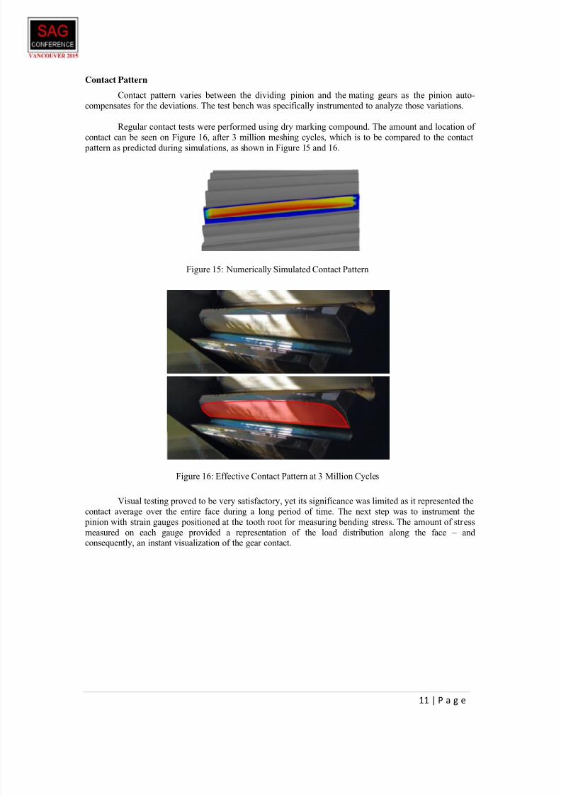
Regular contact tests were performed using dry marking compound. The amount and location of
contact can be seen on Figure 16, after 3 million meshing cycles, which is to be compared to the contact pattern as predicted during simulations, as shown in Figure 15 and 16.
Visual testing proved to be very satisfactory, yet its significance was limited as it represented the
contact average over the entire face during a long period of time. The next step was to instrument the
pinion with strain gauges positioned at the tooth root for measuring bending stress. The amount of stress
measured on each gauge provided a representation of the load distribution along the face – and consequently, an instant visualization of the gear contact.
Figure 16: Effective Contact Pattern at 3 Million Cycles
Figure 15: Numerically Simulated Contact Pattern
7/25/2019 42-Frank Tozlu QdX4, A Mechanical Drive Train Solution for High-Powered Grinding Mills
http://slidepdf.com/reader/full/42-frank-tozlu-qdx4-a-mechanical-drive-train-solution-for-high-powered-grinding 13/18
12 | P a g e
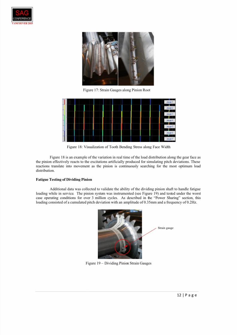
Figure 18 is an example of the variation in real time of the load distribution along the gear face as
the pinion effectively reacts to the excitations artificially produced for simulating pitch deviations. These
reactions translate into movement as the pinion is continuously searching for the most optimum load
distribution.
Fatigue Testing of Dividing Pinion
Additional data was collected to validate the ability of the dividing pinion shaft to handle fatigue
loading while in service. The pinion system was instrumented (see Figure 19) and tested under the worstcase operating conditions for over 3 million cycles. As described in the “Power Sharing” section, this
loading consisted of a cumulated pitch deviation with an amplitude of 0.35mm and a frequency of 0.2Hz.
Figure 19 – Dividing Pinion Strain Gauges
Strain gauge
Figure 17: Strain Gauges along Pinion Root
Figure 18: Visualization of Tooth Bending Stress along Face Width
7/25/2019 42-Frank Tozlu QdX4, A Mechanical Drive Train Solution for High-Powered Grinding Mills
http://slidepdf.com/reader/full/42-frank-tozlu-qdx4-a-mechanical-drive-train-solution-for-high-powered-grinding 14/18
13 | P a g e
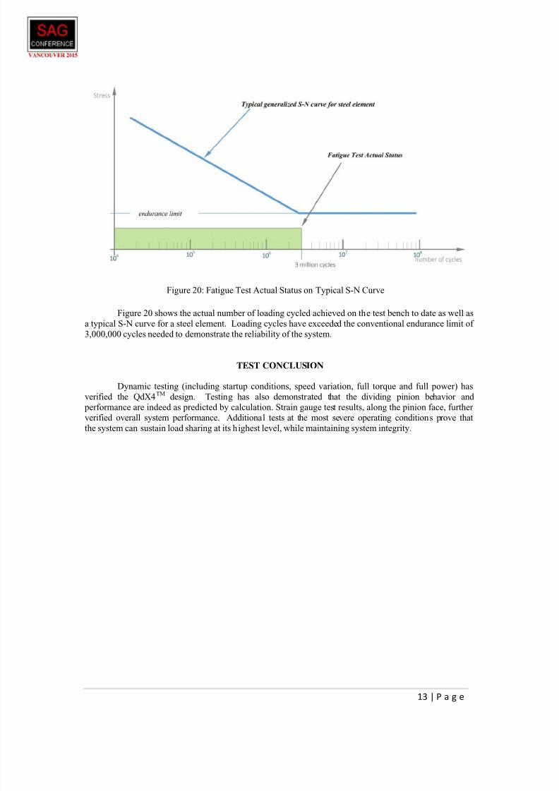
Figure 20: Fatigue Test Actual Status on Typical S-N Curve
Figure 20 shows the actual number of loading cycled achieved on the test bench to date as well as
a typical S-N curve for a steel element. Loading cycles have exceeded the conventional endurance limit of
3,000,000 cycles needed to demonstrate the reliability of the system.
TEST CONCLUSION
Dynamic testing (including startup conditions, speed variation, full torque and full power) has
verified the QdX4TM design. Testing has also demonstrated that the dividing pinion behavior and
performance are indeed as predicted by calculation. Strain gauge test results, along the pinion face, further
verified overall system performance. Additional tests at the most severe operating conditions prove thatthe system can sustain load sharing at its highest level, while maintaining system integrity.
7/25/2019 42-Frank Tozlu QdX4, A Mechanical Drive Train Solution for High-Powered Grinding Mills
http://slidepdf.com/reader/full/42-frank-tozlu-qdx4-a-mechanical-drive-train-solution-for-high-powered-grinding 15/18
14 | P a g e
QdX4TM
GIRTH GEAR
As an integral part of the QdX4TM mill drive, the ring gear also benefits from the latest design
improvements, including material and manufacturing developments.
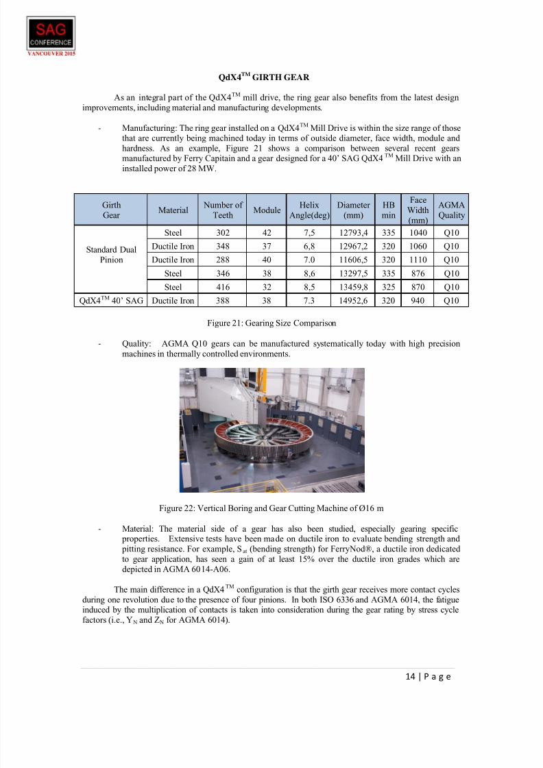
- Manufacturing: The ring gear installed on a QdX4TM Mill Drive is within the size range of thosethat are currently being machined today in terms of outside diameter, face width, module and
hardness. As an example, Figure 21 shows a comparison between several recent gearsmanufactured by Ferry Capitain and a gear designed for a 40’ SAG QdX4TM Mill Drive with an
installed power of 28 MW.
Girth
Gear Material
Number of
TeethModule
Helix
Angle(deg)
Diameter
(mm)
HB
min
Face
Width
(mm)
AGMA
Quality
Standard Dual
Pinion
Steel 302 42 7,5 12793,4 335 1040 Q10
Ductile Iron 348 37 6,8 12967,2 320 1060 Q10
Ductile Iron 288 40 7.0 11606,5 320 1110 Q10
Steel 346 38 8,6 13297,5 335 876 Q10
Steel 416 32 8,5 13459,8 325 870 Q10
QdX4TM 40’ SAG Ductile Iron 388 38 7.3 14952,6 320 940 Q10
Figure 21: Gearing Size Comparison
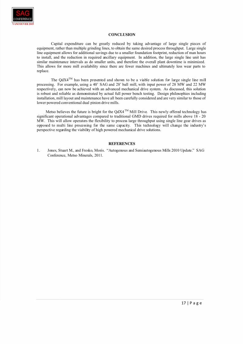
- Quality: AGMA Q10 gears can be manufactured systematically today with high precision
machines in thermally controlled environments.
Figure 22: Vertical Boring and Gear Cutting Machine of Ø16 m
- Material: The material side of a gear has also been studied, especially gearing specific
properties. Extensive tests have been made on ductile iron to evaluate bending strength and pitting resistance. For example, Sat (bending strength) for FerryNod®, a ductile iron dedicated
to gear application, has seen a gain of at least 15% over the ductile iron grades which are
depicted in AGMA 6014-A06.
The main difference in a QdX4TM
configuration is that the girth gear receives more contact cycles
during one revolution due to the presence of four pinions. In both ISO 6336 and AGMA 6014, the fatigueinduced by the multiplication of contacts is taken into consideration during the gear rating by stress cycle
factors (i.e., Y N and Z N for AGMA 6014).

7/25/2019 42-Frank Tozlu QdX4, A Mechanical Drive Train Solution for High-Powered Grinding Mills
http://slidepdf.com/reader/full/42-frank-tozlu-qdx4-a-mechanical-drive-train-solution-for-high-powered-grinding 16/18
15 | P a g e
For example, using AGMA 6014, the difference on the rating between a dual pinion drive and a
QdX4TM will be reduced by approximately 6.7% on pitting and 2.2% on bending. Compensation for this
de-rating can be achieved by an equivalent increase on the face width, an additional 20 HB on hardness or
a slightly larger module.
EXAMPLE OF QdX4TM INSTALLATION AND DESIGN CONSIDERATIONS
The following information and parameters are provided as an example of a typical installation
utilizing the QdX4TM
Mill Drive system and Metso SAG Mill. This example is for information only and isintended to be general in nature. Actual project installation and specifics are determined on a project by
project basis.
Mill Power: 28 megawatt (2 x 14 megawatt)
Mill Speed: 9.16 RPMMill Diameter: 12.8 meter (40.0 feet)
Mill Length: 7.62 meter (25.0 feet)
Motor Speed: 354 RPM
QdX4TM Reduction: 2.29:1
Mill Gearing Reduction: 16.87:1
Figure 23: 28 MW QdX4TM Mill Drive on 40’ SAG Mill

7/25/2019 42-Frank Tozlu QdX4, A Mechanical Drive Train Solution for High-Powered Grinding Mills
http://slidepdf.com/reader/full/42-frank-tozlu-qdx4-a-mechanical-drive-train-solution-for-high-powered-grinding 17/18
16 | P a g e
Overall system considerations for the QdX4TM Mill Drive are nearly identical to that of a typical
dual pinion drive. Some of the benefits and considerations of various sub-systems of the mill assembly are
presented below.
Foundation – Standard foundation loading can be calculated as derived from mill power, critical
speeds, and total mill loading including liners. Similarly, seismic loading can more easily be incorporated
into the model. Unlike gearless drive installations, there is no need to perform lengthy static or dynamicmodal analyses for both short circuit and air gap variances.
Lubrication – Lubrication for the QdX4TM
Mill Drive is provided by a standard lubrication skid mounted system. Two individual systems are being used that can be stored in a lube room away from the
mill operating floor. This type of skid is common in the industry and is easily maintainable. Lubrication
for the open gearing is provided by means of a closed loop oil (or grease) system, and is separate from the
QdX4TM internal torque sharing gearing. This type of lubrication has many benefits that include
continuous application, oil recycling, filtering, and allows for a wide variety of lubricants to be used based
on the site location and availability.
Mill Gearing – The open gearing portion of the design will remain nearly unchanged from that of
a dual pinion drive. Gearing components will be helical and will continue to be rated to AGMA or ISO
service factors as required. Because the power is divided between four pinions, the overall contactload/unit length is reduced. This allows gear sizing to be within currently achievable limits. This alsokeeps the gear material hardness at reasonable levels.
Mill Motor/Drive Train Configuration – Power input to the QdX4TM is similar to conventional
systems that are being used today to power some of the largest dual pinion drive mills in operation. SAG
milling is more effective if the mill speed can be varied during process fluctuations. Higher powered VSD
motors can be used with power inputs of up to 14 MW per drive, extending to 28 MW. Because typical
load sharing VSD motors can be used with the QdX4TM, there is no need to install large brakes and brake
foundation piers as required for GMD installations. Standard holding brakes and hydraulic inching drives
can be used with these types of motors for inching the mill during liner changes and unplanned stoppages,as well as during typical motor maintenance. The methodology of detecting a frozen charge upon start-up
can also still be achieved.
Standardization – In applications where the mill gearing is identical for both the SAG and ball
mills, the QdX4TM mill drive can be designed to share internal components between systems. Since parts
may be interchanged on both types of mills, the number of spare parts is reduced.
QdX4TM Installation – The installation procedure of the QdX4TM is very similar to that of
standard alignment procedures used for dual pinion drive mills. The installation utilizes a base plate that is
bolted to the foundation and grouted in place. Anchor bolts fasten the QdX4TM to the base plate and
adjustment can be made as required for alignment. Gear to pinion alignment is achieved by shimming and
measuring as are done on standard dual pinion alignments. Final alignment is achieved based ontemperature profile across the gear face measured using infrared sensors. Unlike a gearless drive, all
mechanical portions of the installation can be completed by trained site personnel or mill wrights.
Synchronization of the QdX4TM
gearing to the ring gear at installation is easily performed with commontools.
QdX4TM Maintenance – Maintenance on the QdX4TM gear unit has been carefully considered in
the design. Each section of the QdX4TM is designed as a removable unit or cartridge. Therefore
maintenance procedures for any component can be performed on site and/or replaced with a recommended
spare. This design minimizes downtime, increases mill availability and allows trained site personnel to
perform these tasks instead of technical specialists.
7/25/2019 42-Frank Tozlu QdX4, A Mechanical Drive Train Solution for High-Powered Grinding Mills
http://slidepdf.com/reader/full/42-frank-tozlu-qdx4-a-mechanical-drive-train-solution-for-high-powered-grinding 18/18
CONCLUSION
Capital expenditure can be greatly reduced by taking advantage of large single pieces of
equipment, rather than multiple grinding lines, to obtain the same desired process throughput. Large single
line equipment allows for additional savings due to a smaller foundation footprint, reduction of man hours
to install, and the reduction in required ancillary equipment. In addition, the large single line unit has
similar maintenance intervals as do smaller units, and therefore the overall plant downtime is minimized.This allows for more mill availability since there are fewer machines and ultimately less wear parts to
replace.
The QdX4TM has been presented and shown to be a viable solution for large single line mill
processing. For example, using a 40’ SAG and 28’ ball mill, with input power of 28 MW and 22 MW
respectively, can now be achieved with an advanced mechanical drive system. As discussed, this solution
is robust and reliable as demonstrated by actual full power bench testing. Design philosophies including
installation, mill layout and maintenance have all been carefully considered and are very similar to those of
lower powered conventional dual pinion drive mills.
Metso believes the future is bright for the QdX4TM
Mill Drive. This newly offered technology has
significant operational advantages compared to traditional GMD drives required for mills above 18 - 20
MW. This will allow operators the flexibility to process large throughput using single line gear drives asopposed to multi line processing for the same capacity. This technology will change the industry’s
perspective regarding the viability of high powered mechanical drive solutions.
REFERENCES
1. Jones, Stuart M., and Fresko, Moris. “Autogenous and Semiautogenous Mills 2010 Update.” SAG
Conference, Metso Minerals, 2011.