44-pin demo board user guide - microchip...
TRANSCRIPT

2006-2015 Microchip Technology Inc. DS40001296C
44-Pin Demo BoardUser’s Guide
DS40001296C-page 2 2006-2015 Microchip Technology Inc.
Information contained in this publication regarding deviceapplications and the like is provided only for your convenienceand may be superseded by updates. It is your responsibility toensure that your application meets with your specifications.MICROCHIP MAKES NO REPRESENTATIONS ORWARRANTIES OF ANY KIND WHETHER EXPRESS ORIMPLIED, WRITTEN OR ORAL, STATUTORY OROTHERWISE, RELATED TO THE INFORMATION,INCLUDING BUT NOT LIMITED TO ITS CONDITION,QUALITY, PERFORMANCE, MERCHANTABILITY ORFITNESS FOR PURPOSE. Microchip disclaims all liabilityarising from this information and its use. Use of Microchipdevices in life support and/or safety applications is entirely atthe buyer’s risk, and the buyer agrees to defend, indemnify andhold harmless Microchip from any and all damages, claims,suits, or expenses resulting from such use. No licenses areconveyed, implicitly or otherwise, under any Microchipintellectual property rights.
Note the following details of the code protection feature on Microchip devices:
• Microchip products meet the specification contained in their particular Microchip Data Sheet.
• Microchip believes that its family of products is one of the most secure families of its kind on the market today, when used in the intended manner and under normal conditions.
• There are dishonest and possibly illegal methods used to breach the code protection feature. All of these methods, to our knowledge, require using the Microchip products in a manner outside the operating specifications contained in Microchip’s Data Sheets. Most likely, the person doing so is engaged in theft of intellectual property.
• Microchip is willing to work with the customer who is concerned about the integrity of their code.
• Neither Microchip nor any other semiconductor manufacturer can guarantee the security of their code. Code protection does not mean that we are guaranteeing the product as “unbreakable.”
Code protection is constantly evolving. We at Microchip are committed to continuously improving the code protection features of ourproducts. Attempts to break Microchip’s code protection feature may be a violation of the Digital Millennium Copyright Act. If such actsallow unauthorized access to your software or other copyrighted work, you may have a right to sue for relief under that Act.
Microchip received ISO/TS-16949:2009 certification for its worldwide headquarters, design and wafer fabrication facilities in Chandler and Tempe, Arizona; Gresham, Oregon and design centers in California and India. The Company’s quality system processes and procedures are for its PIC® MCUs and dsPIC® DSCs, KEELOQ® code hopping devices, Serial EEPROMs, microperipherals, nonvolatile memory and analog products. In addition, Microchip’s quality system for the design and manufacture of development systems is ISO 9001:2000 certified.
QUALITY MANAGEMENT SYSTEM CERTIFIED BY DNV
== ISO/TS 16949 ==
Trademarks
The Microchip name and logo, the Microchip logo, dsPIC, FlashFlex, flexPWR, JukeBlox, KEELOQ, KEELOQ logo, Kleer, LANCheck, MediaLB, MOST, MOST logo, MPLAB, OptoLyzer, PIC, PICSTART, PIC32 logo, RightTouch, SpyNIC, SST, SST Logo, SuperFlash and UNI/O are registered trademarks of Microchip Technology Incorporated in the U.S.A. and other countries.
The Embedded Control Solutions Company and mTouch are registered trademarks of Microchip Technology Incorporated in the U.S.A.
Analog-for-the-Digital Age, BodyCom, chipKIT, chipKIT logo, CodeGuard, dsPICDEM, dsPICDEM.net, ECAN, In-Circuit Serial Programming, ICSP, Inter-Chip Connectivity, KleerNet, KleerNet logo, MiWi, MPASM, MPF, MPLAB Certified logo, MPLIB, MPLINK, MultiTRAK, NetDetach, Omniscient Code Generation, PICDEM, PICDEM.net, PICkit, PICtail, RightTouch logo, REAL ICE, SQI, Serial Quad I/O, Total Endurance, TSHARC, USBCheck, VariSense, ViewSpan, WiperLock, Wireless DNA, and ZENA are trademarks of Microchip Technology Incorporated in the U.S.A. and other countries.
SQTP is a service mark of Microchip Technology Incorporated in the U.S.A.
Silicon Storage Technology is a registered trademark of Microchip Technology Inc. in other countries.
GestIC is a registered trademarks of Microchip Technology Germany II GmbH & Co. KG, a subsidiary of Microchip Technology Inc., in other countries.
All other trademarks mentioned herein are property of their respective companies.
© 2006-2015, Microchip Technology Incorporated, Printed in the U.S.A., All Rights Reserved.
ISBN: 978-1-63277-381-4
44-PIN DEMO BOARD
USER’S GUIDETable of Contents
Preface ........................................................................................................................... 5
Chapter 1. 44-Pin Demo Board Overview1.1 Introduction ................................................................................................... 111.2 Highlights ...................................................................................................... 111.3 Devices Supported by the 44-Pin Demo Board ............................................ 111.4 44-Pin Demo Board Overview ...................................................................... 121.5 Running the Default Demonstration ............................................................. 13
Chapter 2. PIC® Microcontroller Architectural Overview2.1 Introduction ................................................................................................... 152.2 Memory Organization ................................................................................... 162.3 Programming ................................................................................................ 16
Chapter 3. 44-Pin Demo Board Lessons3.1 Introduction ................................................................................................... 173.2 Program Flowchart ....................................................................................... 173.3 44-Pin Demo Board Lessons ....................................................................... 18
3.3.1 Lesson 1: Hello World (Light a LED) ......................................................... 183.3.2 Lesson 2: Blink (Delay Loop) .................................................................... 193.3.3 Lesson 3: Rotate (Move the LED) ............................................................. 203.3.4 Lesson 4: Analog-to-Digital ....................................................................... 213.3.5 Lesson 5: Variable Speed Rotate .............................................................. 233.3.6 Lesson 6: Reversible Variable Speed Rotate ............................................ 243.3.7 Lesson 7: Interrupt Priorities ..................................................................... 25
3.4 Lessons Not Included ................................................................................... 263.5 MPLAB® Code Configurator (MCC) ............................................................. 26
Appendix A. Hardware SchematicsA.1 Introduction .................................................................................................. 29
Worldwide Sales and Service .................................................................................... 32
2006-2015 Microchip Technology Inc. DS40001296C-page 3

44-Pin Demo Board User’s Guide
NOTES:
DS40001296C-page 4 2006-2015 Microchip Technology Inc.

44-PIN DEMO BOARD
USER’S GUIDEPreface
INTRODUCTION
This chapter contains general information that will be useful to know before using the 44-Pin Demo Board. Items discussed in this chapter include:
• Document Layout
• Conventions Used in this Guide
• Warranty Registration
• Recommended Reading
• The Microchip Web Site
• Development Systems Customer Change Notification Service
• Customer Support
• Revision History
DOCUMENT LAYOUT
This document describes how to use the 44-Pin Demo Board as a development tool to emulate and debug firmware on a target board. The document is organized as follows:
• Chapter 1. “44-Pin Demo Board Overview” – This chapter provides an overview of the 44-Pin Demo Board for Microchip’s 44-pin Thin Quad Flatpack (TQFP) PIC® microcontroller units (MCU).
• Chapter 2. “PIC®Microcontroller Architectural Overview”” – This chapter provides an overview of the PIC microcontroller architecture.
• Chapter 3. “44-Pin Demo Board Lessons” – This chapter provides lessons that introduce mid-range PIC MCU assembly instructions and cover basic 44-Pin Demo Board features.
• Appendix A. “Hardware Schematics” – The appendix illustrates the 44-Pin Demo Board hardware schematic diagram, PCB layout and bill of materials (BOM).
NOTICE TO CUSTOMERS
All documentation becomes dated, and this manual is no exception. Microchip tools and documentation are constantly evolving to meet customer needs, so some actual dialogs and/or tool descriptions may differ from those in this document. Please refer to our web site (www.microchip.com) to obtain the latest documentation available.
Documents are identified with a “DS” number. This number is located on the bottom of each page, in front of the page number. The numbering convention for the DS number is “DSXXXXXA”, where “XXXXX” is the document number and “A” is the revision level of the document.
For the most up-to-date information on development tools, see the MPLAB® IDE online help. Select the Help menu, and then Topics to open a list of available online help files.
2006-2015 Microchip Technology Inc. DS40001296C-page 5

44-Pin Demo Board User’s Guide
CONVENTIONS USED IN THIS GUIDE
This manual uses the following documentation conventions:
DOCUMENTATION CONVENTIONS
Description Represents Examples
Arial font:
Italic characters Referenced books MPLAB® IDE User’s Guide
Emphasized text ...is the only compiler...
Initial caps A window the Output window
A dialog the Settings dialog
A menu selection select Enable Programmer
Quotes A field name in a window or dialog
“Save project before build”
Underlined, italic text with right angle bracket
A menu path File>Save
Bold characters A dialog button Click OK
A tab Click the Power tab
N‘Rnnnn A number in verilog format, where N is the total number of digits, R is the radix and n is a digit.
4‘b0010, 2‘hF1
Text in angle brackets < > A key on the keyboard Press <Enter>, <F1>
Courier New font:
Plain Courier New Sample source code #define START
Filenames autoexec.bat
File paths c:\mcc18\h
Keywords _asm, _endasm, static
Command-line options -Opa+, -Opa-
Bit values 0, 1
Constants 0xFF, ‘A’
Italic Courier New A variable argument file.o, where file can be any valid filename
Square brackets [ ] Optional arguments mcc18 [options] file [options]
Curly brackets and pipe character: { | }
Choice of mutually exclusive arguments; an OR selection
errorlevel {0|1}
Ellipses... Replaces repeated text var_name [, var_name...]
Represents code supplied by user
void main (void){ ...}
DS40001296C-page 6 2006-2015 Microchip Technology Inc.

Preface
WARRANTY REGISTRATION
Please complete the enclosed Warranty Registration Card and mail it promptly. Sending in the Warranty Registration Card entitles users to receive new product updates. Interim software releases are available at the Microchip web site.
RECOMMENDED READING
This user’s guide describes how to use the 44-Pin Demo Board. Other useful documents are listed below. The following Microchip documents are available and recommended as supplemental reference resources.
PIC18F23K20/24K20/25K20/26K20/43K20/44K20/45K20/46K20 Data Sheet 28/40/44-Pin Flash Microcontrollers with nanoWatt XLP Technology (DS41303)
Consult this document for information regarding the PIC18F4XK20 28/40/44-pin Flash-based, 8-bit CMOS microcontrollers with XLP technology.
PICkit™ 3 In-Circuit Debugger/Programmer User’s Guide for MPLAB® X IDE (DS52116)
Consult this document for instructions on how to use the PICkit™ 3 microcontroller programmer software and hardware.
MPLAB® Code Configurator User’s Guide (DS40001725)
Consult this document for information on how to use the MPLAB® Code Configurator (MCC). Access www.microchip.com/code_configurator.html for more information on the MCC.
MPLAB® ICD 3 In-Circuit Debugger User’s Guide for MPLAB X IDE (DS50002081)
Consult this document for more information pertaining to the features and functions of the MPLAB® ICD 3 software.
MPLAB® X IDE User’s Guide (DS50002027)
Consult this document for more information pertaining to the installation and features of the MPLAB X Integrated Development Environment (IDE) software.
Readme Files
For the latest information on using other tools, read the tool-specific Readme files in the Readmes subdirectory of the MPLAB IDE installation directory. The Readme files contain update information and known issues that may not be included in this user’s guide.
2006-2015 Microchip Technology Inc. DS40001296C-page 7

44-Pin Demo Board User’s Guide
THE MICROCHIP WEB SITE
Microchip provides online support via our web site at www.microchip.com. This web site is used as a means to make files and information easily available to customers. Accessible by using your favorite Internet browser, the web site contains the following information:
• Product Support – Data sheets and errata, application notes and sample programs, design resources, user’s guides and hardware support documents, latest software releases and archived software
• General Technical Support – Frequently Asked Questions (FAQs), technical support requests, online discussion groups, Microchip consultant program member listing
• Business of Microchip – Product selector and ordering guides, latest Microchip press releases, listing of seminars and events, listings of Microchip sales offices, distributors and factory representatives
DEVELOPMENT SYSTEMS CUSTOMER CHANGE NOTIFICATION SERVICE
Microchip’s customer notification service helps keep customers current on Microchip products. Subscribers will receive e-mail notification whenever there are changes, updates, revisions or errata related to a specified product family or development tool of interest.
To register, access the Microchip web site at www.microchip.com, click on Customer Change Notification and follow the registration instructions.
The Development Systems product group categories are:
• Compilers – The latest information on Microchip C compilers, assemblers, linkers and other language tools. These include all MPLAB X IDE and MPLAB XC8 compilers; all MPLAB assemblers (including MPASM™ assembler); all MPLAB linkers (including MPLINK™ object linker); and all MPLAB librarians (including MPLIB™ object librarian).
• Emulators – The latest information on Microchip in-circuit emulators.This includes the MPLAB REAL ICE™ and MPLAB ICE 2000 and MPLAB ICE 4000 in-circuit emulators.
• In-Circuit Debuggers – The latest information on the Microchip in-circuit debuggers. This includes MPLAB ICD 3 in-circuit debuggers and PICkit™ 3 debug express.
• MPLAB® X IDE – The latest information on Microchip MPLAB X IDE, the Windows® Integrated Development Environment for development systems tools. This list is focused on the MPLAB IDE, MPLAB IDE Project Manager, MPLAB Editor and MPLAB SIM simulator, MPLAB IDE Project Manager as well as general editing and debugging features.
• Programmers – The latest information on Microchip programmers. These include production programmers such as MPLAB REAL ICE in-circuit emulator, MPLAB ICD 3 in-circuit debugger and MPLAB PM3 and PRO MATE® device programmers. Also included are nonproduction development programmers such as PICSTART® Plus and PICkit 2 and 3.
DS40001296C-page 8 2006-2015 Microchip Technology Inc.

Preface
CUSTOMER SUPPORT
Users of Microchip products can receive assistance through several channels:
• Distributor or Representative
• Local Sales Office
• Field Application Engineer (FAE)
• Technical Support
Customers should contact their distributor, representative or field application engineer (FAE) for support. Local sales offices are also available to help customers. A listing of sales offices and locations is included in the back of this document.
Technical support is available through the web site at:
http://www.microchip.com/support.
REVISION HISTORY
Revision A (August 2006)
• Initial release of this document.
Revision B (December 2006)
• Updated Chapter 1, “PICkit™ 2 Overview”
• Added Chapter 2, “Mid-Range PIC® Microcontroller Architectural Overview”
• Added Chapter 3, “Mid-Range PIC® Microcontroller Architectural Overview”
• Changed PICmicro® to PIC®
• Changed PICkit® to PICkit™
• Removed Development Systems Information Line from Customer Support bulleted list
• Updated schematic in Appendix
Revision C (May 2015)
• Updated the Recommended Reading section in Preface
• Updated for new PIC18F45K20 device
• Removed assembly code and added reference to C code
• Removed lessons 6, 8, 9, 10, 11, 12 in chapter 3
• Replaced MPLAB IDE, PICkit 2 and ICD 2 references with MPLAB X IDE, PICkit 3 and ICD 3, respectively.
2006-2015 Microchip Technology Inc. DS40001296C-page 9

44-Pin Demo Board User’s Guide
NOTES:
DS40001296C-page 10 2006-2015 Microchip Technology Inc.
44-PIN DEMO BOARD
USER’S GUIDEChapter 1. 44-Pin Demo Board Overview
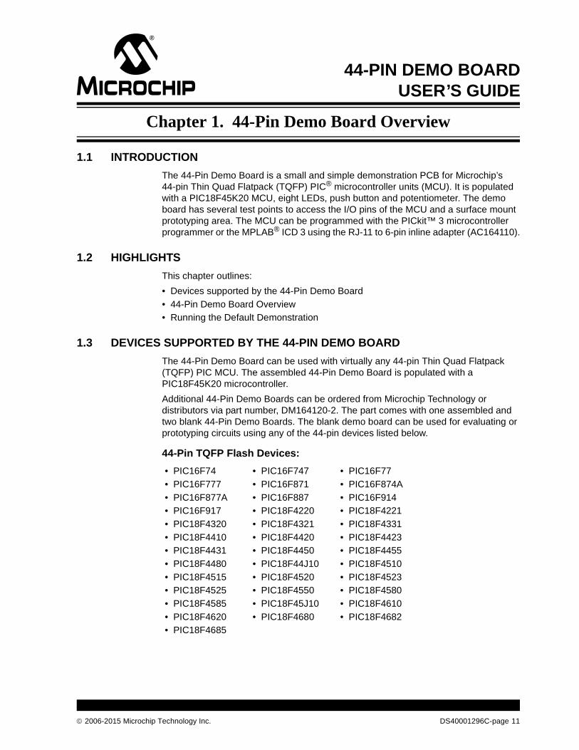
1.1 INTRODUCTION
The 44-Pin Demo Board is a small and simple demonstration PCB for Microchip’s 44-pin Thin Quad Flatpack (TQFP) PIC® microcontroller units (MCU). It is populated with a PIC18F45K20 MCU, eight LEDs, push button and potentiometer. The demo board has several test points to access the I/O pins of the MCU and a surface mount prototyping area. The MCU can be programmed with the PICkit™ 3 microcontroller programmer or the MPLAB® ICD 3 using the RJ-11 to 6-pin inline adapter (AC164110).
1.2 HIGHLIGHTS
This chapter outlines:
• Devices supported by the 44-Pin Demo Board
• 44-Pin Demo Board Overview
• Running the Default Demonstration
1.3 DEVICES SUPPORTED BY THE 44-PIN DEMO BOARD
The 44-Pin Demo Board can be used with virtually any 44-pin Thin Quad Flatpack (TQFP) PIC MCU. The assembled 44-Pin Demo Board is populated with a PIC18F45K20 microcontroller.
Additional 44-Pin Demo Boards can be ordered from Microchip Technology or distributors via part number, DM164120-2. The part comes with one assembled and two blank 44-Pin Demo Boards. The blank demo board can be used for evaluating or prototyping circuits using any of the 44-pin devices listed below.
44-Pin TQFP Flash Devices:
• PIC16F74 • PIC16F747 • PIC16F77
• PIC16F777 • PIC16F871 • PIC16F874A
• PIC16F877A • PIC16F887 • PIC16F914
• PIC16F917 • PIC18F4220 • PIC18F4221
• PIC18F4320 • PIC18F4321 • PIC18F4331
• PIC18F4410 • PIC18F4420 • PIC18F4423
• PIC18F4431 • PIC18F4450 • PIC18F4455
• PIC18F4480 • PIC18F44J10 • PIC18F4510
• PIC18F4515 • PIC18F4520 • PIC18F4523
• PIC18F4525 • PIC18F4550 • PIC18F4580
• PIC18F4585 • PIC18F45J10 • PIC18F4610
• PIC18F4620 • PIC18F4680 • PIC18F4682
• PIC18F4685
2006-2015 Microchip Technology Inc. DS40001296C-page 11

44-Pin Demo Board User’s Guide
1.4 44-PIN DEMO BOARD OVERVIEW
The 44-Pin Demo Board is populated with a PIC18F45K20 MCU (U1), eight LEDs (DS1-DS8), push button (SW1) and potentiometer (RP1). The board layout is shown in Figure 1-1. The demo board has several test points to access the I/O pins of the MCU and a surface mount prototyping area. The MCU can be programmed with the PICkit™ 3 microcontroller programmer from header P1.
FIGURE 1-1: 44-PIN DEMO BOARD
Push Button SW1
Surface Mount
Potentiometer RP1
PICkit™ 3 Programming Header
PrototypingArea
LEDs DS1-DS8
3
DS40001296C-page 12 2006-2015 Microchip Technology Inc.

44-Pin Demo Board Overview
1.5 RUNNING THE DEFAULT DEMONSTRATION
The assembled 44-Pin Demo Board comes preprogrammed with a MCC developed demonstration program. To use this program, power the demo board (3.0-5.5 VDC) using a PICkit™ 3 microcontroller programmer, or a bench power supply connected to header P2.
To use the PICkit™ 3 microcontroller programmer follow these steps:
1. Connect it to a PC USB port using the USB cable
2. Start the MPLAB X IDE application
3. Open the project containing the code for 44-Pin Demo Board
4. Right click on Project to open Project Properties
5. Go to Configuration>PICkit™ 3>Option Categories: Power
6. Select the check box “Power target circuit from PICkit 3”
7. Select the power supply voltage between 3.0 to 5V. The demo program will first light the DS1 LED.
8. Press the push button switch (SW1), to cycle demo program through different states along with the potentiometer (RP1). The demo program is explained in more details in Chapter 3. “44-Pin Demo Board Lessons”.
2006-2015 Microchip Technology Inc. DS40001296C-page 13

44-Pin Demo Board User’s Guide
NOTES:
DS40001296C-page 14 2006-2015 Microchip Technology Inc.
44-PIN DEMO BOARDUSER’S GUIDE
Chapter 2. PIC® Microcontroller Architectural Overview
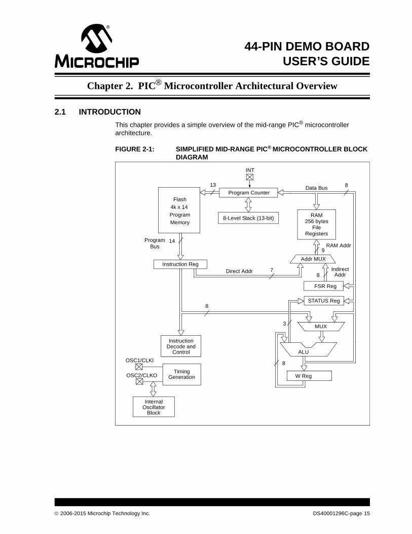
2.1 INTRODUCTION
This chapter provides a simple overview of the mid-range PIC® microcontroller architecture.
FIGURE 2-1: SIMPLIFIED MID-RANGE PIC® MICROCONTROLLER BLOCK DIAGRAM
Flash
Program
Memory
13Data Bus 8
14ProgramBus
Instruction Reg
Program Counter
RAM
FileRegisters
Direct Addr 7
RAM Addr9
Addr MUX
IndirectAddr
FSR Reg
STATUS Reg
MUX
ALU
W Reg
InstructionDecode and
Control
TimingGeneration
OSC1/CLKI
OSC2/CLKO
8
8
8
3
8-Level Stack (13-bit)256 bytes
4k x 14
INT
InternalOscillator
Block
2006-2015 Microchip Technology Inc. DS40001296C-page 15

44-Pin Demo Board User’s Guide
2.2 MEMORY ORGANIZATION
PIC microcontrollers are designed with separate program and data memory areas. This is called Harvard architecture and it allows faster execution as the address and data buses are separate and do not have to do double duty.
Data Memory is divided into File registers, Special Function registers (SFRs) and General Purpose Registers (GPRs). File registers are used by the CPU during execution for quick access; for example, they are used in the case of a loop variable. Instructions referring to File registers use seven bits; therefore, only 128 File registers can be addressed. These registers are arranged in groups of registers called register banks. Access to a register bank is controlled through the STATUS register. Additional banks may or may not be implemented, depending on the device.
The application program interacts with the peripherals and core features through Special Function Registers. SFRs contain peripheral Control registers for operation mode selection, peripheral Data registers for data communication, interrupts etc. The application program writes into these registers so that these peripherals called device drivers can be used.
The General Purpose Registers are also called RAM. They are accessible to program and are used for storing both global and static application variables and also the stack containing local variables and other data.
Program Memory is accessed via the program counter (PC), which stores the program to be executed. The execution unit of the PIC device uses the PC value to get the location of the next queued program instruction to be executed and it auto-increments the PC. The bit length of the PC changes with the device and the program memory size. Refer to the device specific data sheet for PC details and implementation.
The device clock can be provided either from an internal on-chip oscillator or an external crystal oscillator. The application can select the clock using the configuration fuse settings.
2.3 PROGRAMMING
PIC devices are RISC-based MCUs optimized for C programming. This makes C code written for PIC devices and compiled to small-size assembly code take up less program memory and be more efficient in terms of program performance (i.e., higher MIPS).
The compiler optimizes the code to take less stack, data and program memory and it initializes them. Hence, the programmer can focus on peripheral drivers and the application code. For further information on the C compiler for 8-bit PIC devices, refer to the MPLAB® XC8 C Compiler User’s Guide (DS50002053).
DS40001296C-page 16 2006-2015 Microchip Technology Inc.

44-PIN DEMO BOARDUSER’S GUIDE
Chapter 3. 44-Pin Demo Board Lessons
3.1 INTRODUCTION
The following lessons cover basic 44-Pin Demo Board features. Refer to applicable documents as needed. Any updates to the applicable documents are available on Microchip’s web site.
The code and hex files may be installed from Microchip’s web site.
3.2 PROGRAM FLOWCHART
Figure 3-1 shows the initialization of the program. The 44-Pin Demo Board program contains seven lessons or states of program. These states are mentioned in the flowchart as actions or tasks to be performed. These seven lessons show the basic peripherals and their working in PIC MCUs. The initialization program is generated using the MPLAB Code Configurator (MCC) as explained in the following sections. It initializes external INT0 for switch SW1, Analog-to-Digital Converter (ADC) input for potentiometer RP1, Port D output for LED, and Timers, etc.
As shown in Figure 3-1, a key press changes the current action to the next action. The actions are implemented in circular fashion (i.e., after the last action restarts to execute from the first one).
FIGURE 3-1: INITIALIZATION FLOWCHART
Start
Initialize
Switch Interrupt?
YES
NO
B
Advance Action to Next
A
2006-2015 Microchip Technology Inc. DS40001296C-page 17

44-Pin Demo Board User’s Guide
3.3 44-PIN DEMO BOARD LESSONS
The list of lessons is as follows:
• Lesson 1: Hello World (Light a LED)
• Lesson 2: Blink (Delay Loop)
• Lesson 3: Rotate (Move the LED)
• Lesson 4: Analog-to-Digital
• Lesson 5: Variable Speed Rotate
• Lesson 6: Reversible Variable Speed Rotate
• Lesson 7: Interrupt Priorities
3.3.1 Lesson 1: Hello World (Light a LED)
The first lesson shows how to turn on a LED and discusses the I/O pin structures. This is the PIC microcontroller version of “Hello World”.
The LEDs are connected to PORTD from RD0 to RD7 in common cathode configuration. When one of these I/O pins drives high, the LED turns on. The I/O pins can be configured for input or output. On start-up, the default is input. The TRIS Special Function Register bits use the convention of ‘0’ for output and ‘1’ for input. Digital output is targeted, so these must be configured. The LAT register acts as buffer to the output value on the port pin in output configuration.
After setting TRISD as output port in the program, assigning logic ‘1’ to the LATD0 bit of the LATD register turns LED on and vice versa.
FIGURE 3-2: HELLO WORLD FOR PIC® MCU
Action==LED_ON?
Set Port Pin to Light LED
YES
Wait for State Change
A
B NO
DS40001296C-page 18 2006-2015 Microchip Technology Inc.

44-Pin Demo Board Lessons
3.3.2 Lesson 2: Blink (Delay Loop)
The first lesson showed how to turn on a LED; this lesson shows how to make it blink (see Figure 3-3). While this might seem a trivial change from Lesson 1, it gives a context to explore several more peripherals.
FIGURE 3-3: LED BLINK AT PERIODIC RATE USING TIMER0
The LED will blink (i.e., toggled from its current state periodically). The period of toggling is adjusted using a delay loop either in software or hardware. Timer0 is a commonly found core-independent Timer peripheral in almost all 8-bit PIC devices. In the baseline and mid-range devices, Timer0 is an 8-bit timer/counter while in high-end 8-bit PIC MCUs, Timer0 can also be configured as a 16-bit timer/counter. Timer0 can be clocked from either PIC device instruction clock or from an external pin. Once selected, the timer clock can be further prescaled to a smaller clock. Timer0 has eight prescaler options from 1:1 to 1:256 prescaling of the clock.
The TMR0 register holds the timer counter value. It can be preloaded to vary the delay. In Figure 3-3, Timer0 is preloaded with a count. As an up-counter, Timer0 counts to the maximum value (i.e., 255 for eight bits or 65535 for 16 bits). After counter reaches its maximum value, it rolls over to ‘0’ and Timer0 overflow interrupt occurs. The MCU is then interrupted and jumps to a predetermined location to execute the interrupt routine and perform a delay loop task, where LED status is toggled. This is called hardware delay.
The advantage of hardware delay is that delay can be performed independently of the PIC MCU core and the MCU core is free to do other tasks instead of being blocked by the delay task, thus saving CPU cycles and increasing application performance.
To use Timer0, follow these steps in the Configuration register, T0CON:
1. Set the number of bits for the counter (i.e., eight or 16 and select the internal clock).
2. Select the clock edge for Timer operation and prescaler.
3. Write the interrupt routine for Timer0 interrupt void interrupt ISR() and write custom code in it as per application.
4. Start Timer0.
Action==LED_BLINK?
Set Timer Delay
Change LED Port Pin Status
Timer Overflow?
YES
YES
NO
A
B NO
2006-2015 Microchip Technology Inc. DS40001296C-page 19
44-Pin Demo Board User’s Guide
The software delay includes running a loop, either for or while loop in C. Every instruction in the PIC device takes four clock cycles (i.e., one instruction cycle is equal to four clock cycles). In loop, the initialization is done only once; after that, a condition is checked and an increment or decrement operation is performed on the variable that takes part in the condition check. This requires one instruction cycle to perform the math operation, and another instruction cycle for the condition check. Therefore, if the clock is running at 4 MHz, a single execution of the loop for the 8-bit integer takes 2 us of delay time. The advantage of software delay is that it does not require help from peripherals in order to perform. The disadvantages are that CPU cycles are wasted in delay, blocking other important tasks, and the user has to do all calculations at C instruction level, which may vary depending on the compiler optimization for the delay program (i.e., if the compiler uses the RAM location for the variable, another instruction is required to load or store the variable in RAM).
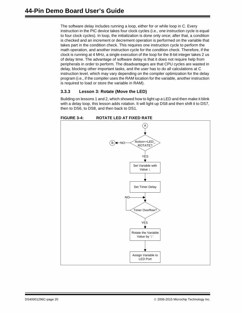
3.3.3 Lesson 3: Rotate (Move the LED)
Building on lessons 1 and 2, which showed how to light up a LED and then make it blink with a delay loop, this lesson adds rotation. It will light up DS8 and then shift it to DS7, then to DS6, to DS8, and then back to DS1.
FIGURE 3-4: ROTATE LED AT FIXED RATE
Action==LED_ROTATE?
Set Variable with Value 1
Set Timer Delay
Timer Overflow?
Rotate the Variable Value by ‘1’
Assign Variable to LED Port
YES
YES
NO
B
A
NO
DS40001296C-page 20 2006-2015 Microchip Technology Inc.

44-Pin Demo Board Lessons
The program flow to rotate the lighting of the LEDs is listed below:
1. First, initialize the I/O port and the display.
2. Copy the display variable to the I/O port.
3. Delay for a little while.
4. Rotate the display.
In this lesson, the delay is given by hardware Timer0 previously explained. An unsigned 8-bit integer variable is used to store value of decimal ‘1’. To rotate the lighting of the LEDs, after Timer0 delay, this variable is shifted left so that only one bit in decimal value is logic ‘1’ while the other are logic ‘0’. The rate at which the lighting of the LEDs rotates depends on Timer0 delay. Next the variable is updated with the new value; then, it is assigned to the I/O port connected to the LEDs (i.e., LATD register for PORTD).
3.3.4 Lesson 4: Analog-to-Digital
This lesson shows how to configure the ADC, run a conversion, read the analog voltage controlled by the potentiometer (RP1) on the board, and display the high-order eight bits on the LEDs.
FIGURE 3-5: ADC DISPLAY ON LED
Configure ADC for Port Input
Action==A/D?
Set Timer Delay
Timer Overflow?
Start ADC Acquisition
Set the High-Order Bits of ADC Out to
LED Port
ADC Done?
YES
YES
YES
NO
NO
A
B NO
2006-2015 Microchip Technology Inc. DS40001296C-page 21

44-Pin Demo Board User’s Guide
PIC18F45K20 has an on-board ADC with ten bits of resolution on any of the 13 channels. The converter can be referenced to the device’s VDD or an external voltage reference. The 44-Pin Demo Board references it to VDD as provided by the PICkit 3 microcontroller programmer. The answer from the ADC is represented by a ratio of the voltage to the reference (see Equation 3-1).
EQUATION 3-1:
Converting the answer from the ADC back to voltage requires solving for V (see Equation 3-2).
EQUATION 3-2:
Two of the three factors on the right-hand side of the equation are constants and may be calculated in advance. This eliminates the need to actually divide, but it still requires fixed or floating point multiply to solve the equation on the fly.
However, calculating the voltage is sometimes only the first step. There may be additional math to calculate the meaningful data from the sensor. For example, when reading a thermistor, calculating the voltage is only the first step on the way to getting the temperature.
There are other means to convert ADC values, including a straight table look-up or a piece-wise linear interpolation. Each of these represents different speed/memory trade-offs.
The schematic in Appendix A. “Hardware Schematics” shows that the wiper on the potentiometer is connected to pin RA0 on PIC18F45K20.
Below is the checklist for this lesson:
1. Configure PORTA as an analog input, TRISA<0> = 1, ANSEL<0> = 1.
2. Select channel in ADCON0.
3. Select VREF source in ADCON1.
4. Select justification, acquisition time and clock in ADCON2.
Refer to the device-specific data sheet for further information on control registers. The high-order eight bits of the ADC result are then displayed on the LED port neglecting the lower two bits.
ADC V VREF 1023=
V ADC 1023 VREF=
DS40001296C-page 22 2006-2015 Microchip Technology Inc.

44-Pin Demo Board Lessons
3.3.5 Lesson 5: Variable Speed Rotate
Lesson 5 combines lessons 3 and 4 by using the ADC to control the speed of rotation.
FIGURE 3-6: ROTATE LED CLOCKWISE OR FORWARD AT VARIABLE RATE
In this lesson, Timer0 is used as variable delay counter, the delay of which is changed according to the ADC output of the RP1 potentiometer connected to the ADC channel, AN0. Timer1 is used to set the sampling frequency for the ADC. When Timer1 times out, it enables the ADC conversion. The ADC output is used to change the Timer0 delay. As the potentiometer RP1 resistance changes, the rate at which the LED is rotating changes accordingly.
Action==VAR_LED_ROTATE?
Set Variable with Value ‘1’
Set Timer1 Delay for ADC
Timer1 Overflow?
Start ADC Acquisition
ADC Done?
Set Timer2 Delay for LED Rotation
Change Timer2 Delay Proportional to ADC
Out
Configure ADC for Port Input
Timer2 Overflow?
Rotate Variable by ‘1’
Assign Variable to LED Port
YES
YES YES
YES
NO
NO NO
A
NO
2006-2015 Microchip Technology Inc. DS40001296C-page 23

44-Pin Demo Board User’s Guide
3.3.6 Lesson 6: Reversible Variable Speed Rotate
Lesson 6 is similar to Lesson 5 (i.e., the system and peripherals have the same functions as explained in Lesson 5, except that the LED rotation direction is reversed).
FIGURE 3-7: ROTATE LED ANTI-CLOCKWISE/REVERSE AT VARIABLE RATE
Action==REVERSE_VAR_LED_ROTATE?
Set Variable with Value 0x80
Set Timer1 Delay for ADC
Timer1 Overflow?
Start ADC Acquisition
ADC Done?
Set Timer2 Delay for LED Rotation
Change Timer2 Delay Proportional to ADC Out
Configure ADC for Port Input
Timer2 Overflow?
Rotate Variable by ‘1’ in Reverse Direction
Assign Variable to LED Port
YES YES
YES
NO
NO NO
YES
NO
A
B
DS40001296C-page 24 2006-2015 Microchip Technology Inc.

44-Pin Demo Board Lessons
3.3.7 Lesson 7: Interrupt Priorities
This lesson focuses on interrupt priorities in high-end PIC16F and PIC18F devices. The external interrupt INT0 is connected to the SW1 switch which is a high-priority interrupt. The Timer0 overflow interrupt is a low-priority interrupt, which is used to blink LED DS0 at a constant rate set by the user. When SW1 is pressed, the high-priority external interrupt takes priority over the low-priority Timer0 interrupt and stops LED from blinking for a second and lights the DS1 LED. After a second, the DS1 LED is turned off and Timer0 resumes blinking the DS0 LED. This lesson explains when the low-priority interrupt is being serviced; it can be interrupted by high-priority interrupts.
FIGURE 3-8: INTERRUPT PRIORITY TEST
Action==INTERRUPT_TEST?
Init Timer0 for LED1 Blink
Set Timer1 Low and External Switch High Interrupt Priority
YES
Timer1 Overflow? Switch Press?
Change LED1 StatusStop LED 1 Blink, ON LED2 for
1 Second
YES YES
NO
NO
Note: The switch interrupt is high priority; therefore, it will automatically stop Timer interrupt, which is low priority; however, it will resume when switch interrupt is done delaying.
A
B NO
2006-2015 Microchip Technology Inc. DS40001296C-page 25

44-Pin Demo Board User’s Guide
3.4 LESSONS NOT INCLUDED
There are some tasks which are inherently part of the program such as switch debouncing or Timer0 delay. Hence, these lessons from the previous versions of this user guide are not included as separate lessons in the current version. Following is the list of lessons that can be found in previous versions of the document:
• Function Calls
• Timer0
• Indirect Data Addressing
• Look-up Table
3.5 MPLAB® CODE CONFIGURATOR (MCC)
The MPLAB® X Code Configuration tool is used in this project to generate driver application programming interfaces (APIs) for the peripherals used. It is the simplest and fastest way to generate code. The peripherals used in this program are:
• Timer0 – delay timer
• Timer1 – used for setting ADC sampling frequency
• ADC – channel AN0 for potentiometer RP1
• INT0 – external interrupt for switch SW1
• PORTD – LED output port
To install the MCC, go to Tools>Plugins>Available Plugins>MPLAB X Code Configurator>Install.
To start and use the MCC after installation, go to Tools>Embedded>MPLAB Code Configurator.
FIGURE 3-9: ADC SETTINGS USING THE MCC
As seen in Figure 3-9, the clock, VREF, acquisition time, channel selection, interrupt enable are all set by GUI at one place.
DS40001296C-page 26 2006-2015 Microchip Technology Inc.

44-Pin Demo Board Lessons
FIGURE 3-10: TIMER0 SETTINGS USING MCC
Similar to Figure 3-9, Figure 3-10 shows the Timer0 settings. In both figures, the port pin settings are given on the right-hand side. In a similar way, other settings are performed in the MCC. After all system settings are done, click the Generate Code button in the upper left-hand side corner of the MPLAB Code Configurator window. This will generate all peripheral-related code in a MCC file structure along with the main.c file, where the user can call these initialization functions at will and focus on the actual application code.
2006-2015 Microchip Technology Inc. DS40001296C-page 27

44-Pin Demo Board User’s Guide
NOTES:
DS40001296C-page 28 2006-2015 Microchip Technology Inc.

44-PIN DEMO BOARDUSER’S GUIDE
Appendix A. Hardware Schematics
A.1 INTRODUCTION
This appendix contains the 44-Pin Demo Board schematic, PCB layout and Bill of Materials (BOM).
FIGURE A-1: 44-PIN DEMO BOARD SCHEMATIC DIAGRAM
PIC
®
2006-2015 Microchip Technology Inc. DS40001296C-page 29

44-Pin Demo Board User’s Guide
FIGURE A-2: 44-PIN DEMO BOARD SILKSCREEN
FIGURE A-3: 44-PIN DEMO BOARD TOP COPPER
DS40001296C-page 30 2006-2015 Microchip Technology Inc.

Hardware Schematics
FIGURE A-4: 44-PIN DEMO BOARD BOTTOM COPPER
TABLE A-1: 44-PIN DEMO BOARD BILL OF MATERIALS
Bill of Materials
Designation Qty Description
C1, C2, C3 3 Capacitor, Ceramic, 0805 SMT, 0.1 F, 16V, 5%, X7R
R5-R12 8 Resistor, 0805 SMT, 750, 5%, 1/8W
R1, R3 2 Resistor, 0805 SMT, 1 k 5%, 1/8W
R2 1 Resistor, 0805 SMT, 10 k, 5%, 1/8W
RP1 1 Potentiometer 10 k, thumbwheel
DS1-DS8 8 LED, 0805 SMT, Red Clear
SW1 1 Switch, push button, momentary
U1 – Microcontroller 1 44-pin PIC® MCU
P1 1 Connector, header, right-angle, 6-pin, 0.100” spacing, 0.025” square
JP1 1 Connector, header, 2-pin, 0.100” spacing, 0.025” square
Rubber feet 4 Bumpon square, 0.40 x 0.10, black
2006-2015 Microchip Technology Inc. DS40001296C-page 31

DS40001296C-page 32 2006-2015 Microchip Technology Inc.
AMERICASCorporate Office2355 West Chandler Blvd.Chandler, AZ 85224-6199Tel: 480-792-7200 Fax: 480-792-7277Technical Support: http://www.microchip.com/supportWeb Address: www.microchip.com
AtlantaDuluth, GA Tel: 678-957-9614 Fax: 678-957-1455
Austin, TXTel: 512-257-3370
BostonWestborough, MA Tel: 774-760-0087 Fax: 774-760-0088
ChicagoItasca, IL Tel: 630-285-0071 Fax: 630-285-0075
ClevelandIndependence, OH Tel: 216-447-0464 Fax: 216-447-0643
DallasAddison, TX Tel: 972-818-7423 Fax: 972-818-2924
DetroitNovi, MI Tel: 248-848-4000
Houston, TX Tel: 281-894-5983Indianapolis
Noblesville, IN Tel: 317-773-8323Fax: 317-773-5453
Los AngelesMission Viejo, CA Tel: 949-462-9523 Fax: 949-462-9608
New York, NY Tel: 631-435-6000
San Jose, CA Tel: 408-735-9110
Canada - TorontoTel: 905-673-0699 Fax: 905-673-6509
ASIA/PACIFICAsia Pacific OfficeSuites 3707-14, 37th FloorTower 6, The GatewayHarbour City, Kowloon
Hong KongTel: 852-2943-5100Fax: 852-2401-3431
Australia - SydneyTel: 61-2-9868-6733Fax: 61-2-9868-6755
China - BeijingTel: 86-10-8569-7000 Fax: 86-10-8528-2104
China - ChengduTel: 86-28-8665-5511Fax: 86-28-8665-7889
China - ChongqingTel: 86-23-8980-9588Fax: 86-23-8980-9500
China - DongguanTel: 86-769-8702-9880
China - HangzhouTel: 86-571-8792-8115 Fax: 86-571-8792-8116
China - Hong Kong SARTel: 852-2943-5100 Fax: 852-2401-3431
China - NanjingTel: 86-25-8473-2460Fax: 86-25-8473-2470
China - QingdaoTel: 86-532-8502-7355Fax: 86-532-8502-7205
China - ShanghaiTel: 86-21-5407-5533 Fax: 86-21-5407-5066
China - ShenyangTel: 86-24-2334-2829Fax: 86-24-2334-2393
China - ShenzhenTel: 86-755-8864-2200 Fax: 86-755-8203-1760
China - WuhanTel: 86-27-5980-5300Fax: 86-27-5980-5118
China - XianTel: 86-29-8833-7252Fax: 86-29-8833-7256
ASIA/PACIFICChina - XiamenTel: 86-592-2388138 Fax: 86-592-2388130
China - ZhuhaiTel: 86-756-3210040 Fax: 86-756-3210049
India - BangaloreTel: 91-80-3090-4444 Fax: 91-80-3090-4123
India - New DelhiTel: 91-11-4160-8631Fax: 91-11-4160-8632
India - PuneTel: 91-20-3019-1500
Japan - OsakaTel: 81-6-6152-7160 Fax: 81-6-6152-9310
Japan - TokyoTel: 81-3-6880- 3770 Fax: 81-3-6880-3771
Korea - DaeguTel: 82-53-744-4301Fax: 82-53-744-4302
Korea - SeoulTel: 82-2-554-7200Fax: 82-2-558-5932 or 82-2-558-5934
Malaysia - Kuala LumpurTel: 60-3-6201-9857Fax: 60-3-6201-9859
Malaysia - PenangTel: 60-4-227-8870Fax: 60-4-227-4068
Philippines - ManilaTel: 63-2-634-9065Fax: 63-2-634-9069
SingaporeTel: 65-6334-8870Fax: 65-6334-8850
Taiwan - Hsin ChuTel: 886-3-5778-366Fax: 886-3-5770-955
Taiwan - KaohsiungTel: 886-7-213-7828
Taiwan - TaipeiTel: 886-2-2508-8600 Fax: 886-2-2508-0102
Thailand - BangkokTel: 66-2-694-1351Fax: 66-2-694-1350
EUROPEAustria - WelsTel: 43-7242-2244-39Fax: 43-7242-2244-393
Denmark - CopenhagenTel: 45-4450-2828 Fax: 45-4485-2829
France - ParisTel: 33-1-69-53-63-20 Fax: 33-1-69-30-90-79
Germany - DusseldorfTel: 49-2129-3766400
Germany - MunichTel: 49-89-627-144-0 Fax: 49-89-627-144-44
Germany - PforzheimTel: 49-7231-424750
Italy - Milan Tel: 39-0331-742611 Fax: 39-0331-466781
Italy - VeniceTel: 39-049-7625286
Netherlands - DrunenTel: 31-416-690399 Fax: 31-416-690340
Poland - WarsawTel: 48-22-3325737
Spain - MadridTel: 34-91-708-08-90Fax: 34-91-708-08-91
Sweden - StockholmTel: 46-8-5090-4654
UK - WokinghamTel: 44-118-921-5800Fax: 44-118-921-5820
Worldwide Sales and Service
01/27/15