document4
TRANSCRIPT

The Department for Business, Innovation and Skills
Fleetbank House 3rd, 7th and 8th floor refurbishment and associated Works
Mechanical & Electrical Services Scope of Works
January 2014

Fleetbank House level 3, 7 and 8 refurbishment and associated Works: Mechanical and Electrical Services scope of works
echarris.com 1
Copyright © 2011 EC Harris. All rights reserved
An ARCADIS company.
EC Harris LLP is a limited liability partnership, registered in England, registered number OC368843. Registered office, ECHQ, 34 York Way, London, N1 9AB. A list of the members' names is available for inspection at the above office. Part of the ARCADIS Group of Companies, along with other entities in the UK, including EC Harris (UK) Limited. Regulated by RICS.
Contacts
Dan Birks
Senior Building Services Engineer
dd 020 7812 2533
df 020 7812 2005
m 07770 647 372
EC Harris Solutions Ltd ECHQ, 34 York Way
London N1 9AB
United Kingdom
Fleetbank House level 3, 7 and 8 refurbishment and associated Works: Mechanical and Electrical Services scope of works
echarris.com 2
Copyright © 2011 EC Harris. All rights reserved
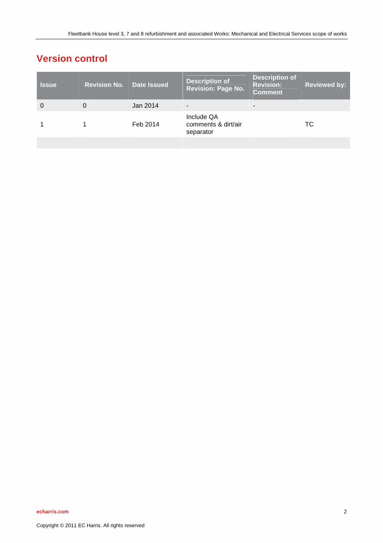
Version control
Issue Revision No. Date Issued Description of Revision: Page No.
Description of Revision: Comment
Reviewed by:
0 0 Jan 2014 - -
1 1 Feb 2014 Include QA comments & dirt/air separator
TC
Fleetbank House level 3, 7 and 8 refurbishment and associated Works: Mechanical and Electrical Services scope of works
echarris.com 3
Copyright © 2011 EC Harris. All rights reserved
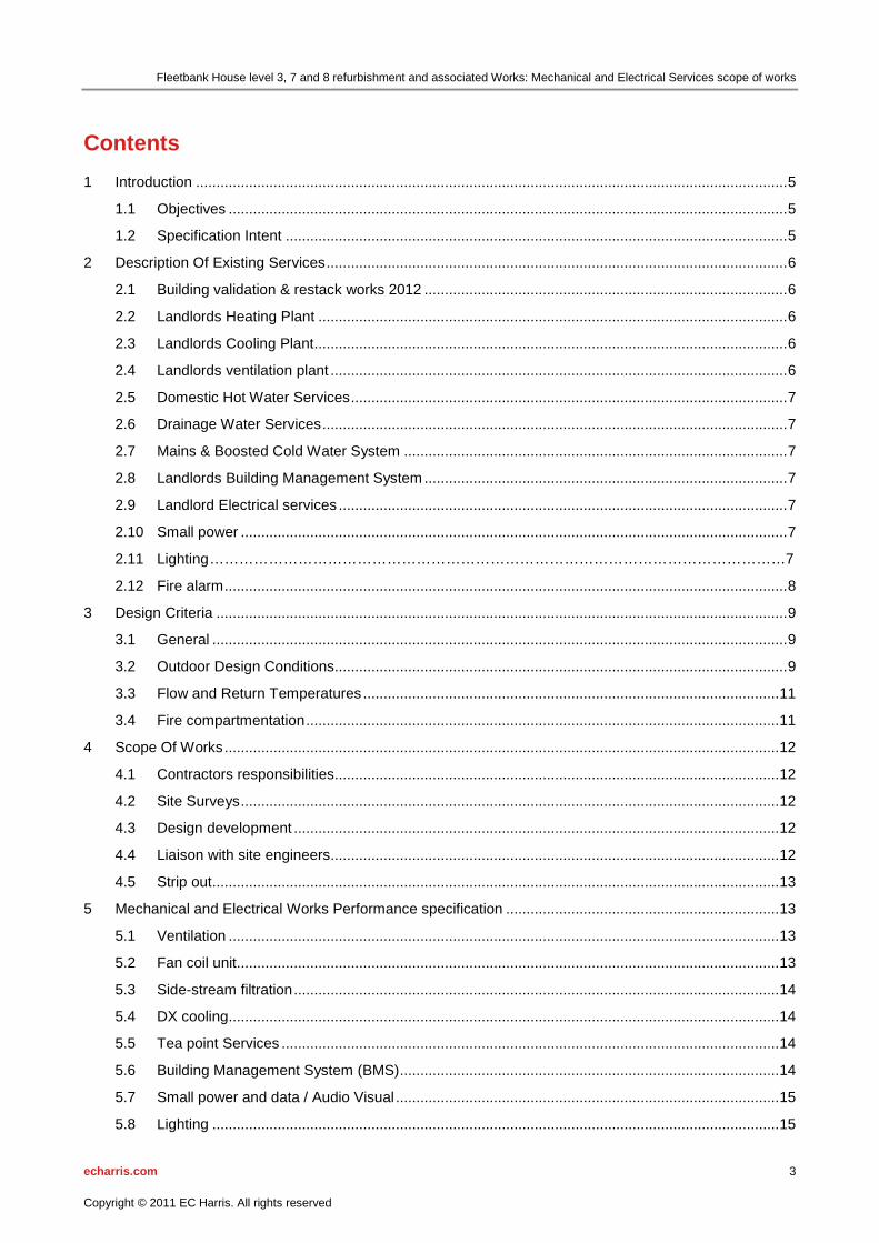
Contents
1 Introduction ................................................................................................................................................. 5
1.1 Objectives ......................................................................................................................................... 5
1.2 Specification Intent ........................................................................................................................... 5
2 Description Of Existing Services ................................................................................................................. 6
2.1 Building validation & restack works 2012 ......................................................................................... 6
2.2 Landlords Heating Plant ................................................................................................................... 6
2.3 Landlords Cooling Plant .................................................................................................................... 6
2.4 Landlords ventilation plant ................................................................................................................ 6
2.5 Domestic Hot Water Services ........................................................................................................... 7
2.6 Drainage Water Services .................................................................................................................. 7
2.7 Mains & Boosted Cold Water System .............................................................................................. 7
2.8 Landlords Building Management System ......................................................................................... 7
2.9 Landlord Electrical services .............................................................................................................. 7
2.10 Small power ...................................................................................................................................... 7
2.11 Lighting ………………………………………………………………………………………………………7
2.12 Fire alarm .......................................................................................................................................... 8
3 Design Criteria ............................................................................................................................................ 9
3.1 General ............................................................................................................................................. 9
3.2 Outdoor Design Conditions............................................................................................................... 9
3.3 Flow and Return Temperatures ...................................................................................................... 11
3.4 Fire compartmentation .................................................................................................................... 11
4 Scope Of Works ........................................................................................................................................ 12
4.1 Contractors responsibilities ............................................................................................................. 12
4.2 Site Surveys .................................................................................................................................... 12
4.3 Design development ....................................................................................................................... 12
4.4 Liaison with site engineers .............................................................................................................. 12
4.5 Strip out ........................................................................................................................................... 13
5 Mechanical and Electrical Works Performance specification ................................................................... 13
5.1 Ventilation ....................................................................................................................................... 13
5.2 Fan coil unit..................................................................................................................................... 13
5.3 Side-stream filtration ....................................................................................................................... 14
5.4 DX cooling....................................................................................................................................... 14
5.5 Tea point Services .......................................................................................................................... 14
5.6 Building Management System (BMS) ............................................................................................. 14
5.7 Small power and data / Audio Visual .............................................................................................. 15
5.8 Lighting ........................................................................................................................................... 15

Fleetbank House level 3, 7 and 8 refurbishment and associated Works: Mechanical and Electrical Services scope of works
echarris.com 4
Copyright © 2011 EC Harris. All rights reserved
5.9 Fire alarm ........................................................................................................................................ 16
5.10 Access control & Hearing loop........................................................................................................ 16
5.11 Builders Work ................................................................................................................................. 16
5.12 Testing And Commissioning ........................................................................................................... 17
5.13 Record Drawings, Operating And Maintenance Manuals .............................................................. 18
5.14 Handover ........................................................................................................................................ 19
5.15 Responsibility During The Defects Liability Period ......................................................................... 20
6 SUMMARY OF COSTS ............................................................................................................................ 21
6.1 SCHEDULE OF RATES ................................................................................................................. 23

Fleetbank House level 3, 7 and 8 refurbishment and associated Works: Mechanical and Electrical Services scope of works
echarris.com 5
Copyright © 2011 EC Harris. All rights reserved
1 Introduction The works referred to in this document are for the refurbishment of levels 3, 7 and 8 and associated works at ground and lower ground level of Fleetbank House for Business, Innovation and Skills (BIS).
The Contractor shall note that the items of work contained in the following sections have been described in reasonable detail, but the Contractor shall consider them in conjunction with the preliminaries, preambles, and main contract. The Contractor shall also allow in his price everything necessary to carry out the works in the best manner all in accordance with current relevant regulations and established codes of practice whether specifically mentioned or not.
This scope of works should be read in conjunction with the Mechanical and Electrical Services Materials and Workmanship specification clauses.
Where there is a conflict between the Preliminaries, Preambles, Specification or the standards within this document and the current Building Regulations, the Contractor shall immediately draw this to the attention of the Project Manager (PM) for agreement as to which will take precedence.
Limited records of the existing building services are available.
All values provided within this Specification are for guidance only. This includes, but is not limited to design criteria, cooling capacity, number of plant, etc.
1.1 Objectives The successful outcome of this project is to undertake necessary mechanical and electrical services modifications to suit the CAT B fit out of floors 3, 7 and 8 and associated works at ground and lower ground of Fleetbank House.
1.2 Specification Intent This Contract is a NEC3 Option A Contract, Design and Build with Contractor’s Design. The Contractor shall be aware that this Specification sets out the basic design intent of the Works and the Contractor when pricing the Works shall be fully aware that he is responsible for all design, selection procurement, installation, setting to work, testing and commissioning and successful performance of the system/s.

Fleetbank House level 3, 7 and 8 refurbishment and associated Works: Mechanical and Electrical Services scope of works
echarris.com 6
Copyright © 2011 EC Harris. All rights reserved
2 Description Of Existing Services
2.1 Building validation & restack works 2012 A re-stack of floors 3-9 and re-balance of the main HVAC plant was undertaken in 2012. The contractor can use this information however we cannot guarantee the accuracy.
2.2 Landlords Heating Plant Heating is provided by a central Low Temperature Hot Water (LTHW) system, served by three gas-fired boilers located within basement level 1 boiler plant room. There are four main distribution circuits plus a common primary circuit. Each circuit is served by duty/standby pump sets as follows:
• LTHW primary
• LTHW constant temperature Fan Coil Unit (FCU) circuit.
• LTHW constant temperature Air Handling Unit (AHU) circuit.
• LTHW constant temperature 24 hour circuit.
• LTHW variable temperature radiator circuit.
2.3 Landlords Cooling Plant Cooling is provided by a central Chilled water (CHW) system, served by two air-cooled chillers located at roof level (9th floor). There are two main landlord distribution circuits plus a primary circuit for each of the chillers.
Each circuit is served by duty/standby pump sets as follows:
• CHW primary.
• CHW constant temperature FCU circuit.
• CHW constant temperature AHU circuit.
The 24 hour cooling is by a CHW system, served by an air-cooled chiller located within basement level 1 plant room 27. There is one main distribution circuit plus a primary circuit for the chiller. Each circuit is served by duty/standby pump sets as follows:
• CHW primary.
• CHW constant temperature 24 hour circuit.
The 24 hour unit provides environmental conditions within the following specialised areas:
• Archive AHU 4.
• Communications room AC1.
• Patch rooms up to third floor level.
All the above systems are installed in a two pipe arrangement and are each pressurised.
2.4 Landlords ventilation plant The main air conditioning/ventilation system comprises of a number of central supply and extract systems, served by Air Handling Units (AHU’s) which are located within various areas of the level 1 basement. The main AHU’s serving the office accommodation including the 2nd floor accommodation is as follows;
• AHU No. 5 South core office accommodation.
• AHU No. 6 Central core office accommodation.
• AHU No. 8 North core office accommodation.
The AHU’s supply comfort conditioned primary fresh air to the office accommodation and operates in conjunction with locally mounted 4-pipe fan coil units (FCU’s). The FCU’s consist of low level perimeter mounted cased units and ceiling mounted units. Both types of units re-circulate air, however, air to the ceiling unit’s is mixed with fresh air from the central AHU’s.

Fleetbank House level 3, 7 and 8 refurbishment and associated Works: Mechanical and Electrical Services scope of works
echarris.com 7
Copyright © 2011 EC Harris. All rights reserved
2.5 Domestic Hot Water Services Domestic hot water is provided to the toilets, tea points and cleaner’s sinks by locally mounted electric water heaters which are strategically located at each level.
2.6 Drainage Water Services Soil, waste and drainage distribution systems throughout the property are generally constructed from a mix of cast iron and plastic pipe work.
2.7 Mains & Boosted Cold Water System The metered potable water supply enters the property at basement level and feeds the café/deli and the boosted water services, tearooms and roof down service tanks. The down service tanks provide water to the toilets and cleaner’s sinks.
2.8 Landlords Building Management System The installed mechanical services are controlled by a fully automatic Sauter closed protocol BMS where controllers are now obsolete. The head end central supervisor for the system being located within the maintenance contractor’s office at basement level 1. BMS outstations are located within various motor control panels situated throughout the property. The system provides automatic control of the plant operation to maintain design settings and control run times, with full plant status and fault monitoring.
2.9 Landlord Electrical services The property is provided with four public utility low voltage electrical supplies, two rated at 1200 Amps and two rated at 800 Amps. Each supply feeds a low voltage switchboard which is located within basement level No 2 switch room. An automatic power factor correction unit serves the low voltage switchboard. The outgoing distribution cables are via moulded case circuit breakers and supply various Landlord and Tenant’s sub-mains distribution boards, mechanical service plant and lifts. There are bus bar trunking systems installed within service core electrical risers, these extend from lower ground floor to ninth floor and provide the small power distribution to both landlord’s and tenant’s distribution boards via tap-off boxes. The Landlords and Tenant’s local distribution boards at each level serve the small power, lighting and office accommodation floor mounted fused connection units’ and incorporate bulk-switching contactors linked to the BMS. The uninterrupted power supply (UPS) installation consists of six stand alone units serving the communications room and five local Patch rooms located within the office accommodation demise. It is understood that the UPS is sized to provide battery backup of 40 minutes for the communications room and 20 minutes for the Patch rooms.
2.10 Small power The office accommodation small power is provided via a raised floor bus bar power track system with recessed floor service outlet boxes and the multi compartment wall mounted skirting trunking system (each outlet box containing facilities for power, voice and data) to suit new office layout. The existing general open plan office area is electrically fed by an “electrac” floor void mounted bus bar system. In addition local socket outlets are provided on the perimeter fan coil unit casings. Fan coil units are provided power via switched fused spurs located within the perimeter casings and within the suspended ceiling void.
2.11 Lighting The general office accommodation lighting is by recessed modular luminaires incorporating stand-alone proximity detectors and automatic dimming command modules. The emergency lighting is provided by integral or remote emergency inverter/battery power packs fitted to a percentage of normal light fittings.

Fleetbank House level 3, 7 and 8 refurbishment and associated Works: Mechanical and Electrical Services scope of works
echarris.com 8
Copyright © 2011 EC Harris. All rights reserved
2.12 Fire alarm A Honeywell Gent Vigilon analogue addressable fire alarm panel by is located at reception. A voice alarm system serves the whole building linked with manual call points and smoke detection. The fire alarm is currently maintained by Trident.
Fleetbank House level 3, 7 and 8 refurbishment and associated Works: Mechanical and Electrical Services scope of works
echarris.com 9
Copyright © 2011 EC Harris. All rights reserved
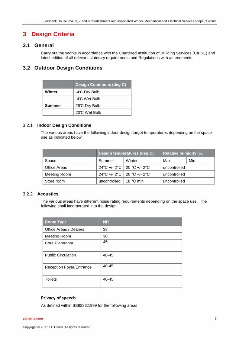
3 Design Criteria
3.1 General Carry out the Works in accordance with the Chartered Institution of Building Services (CIBSE) and latest edition of all relevant statutory requirements and Regulations with amendments.
3.2 Outdoor Design Conditions
Design Conditions (deg C)
Winter -4°C Dry Bulb
-4°C Wet Bulb
Summer 29°C Dry Bulb
20°C Wet Bulb
Indoor Design Conditions 3.2.1
The various areas have the following indoor design target temperatures depending on the space use as indicated below:
Design temperatures (deg C) Relative humidity (%)
Space Summer Winter Max. Min.
Office Areas 24°C +/- 2°C 20 °C +/- 2°C uncontrolled
Meeting Room 24°C +/- 2°C 20 °C +/- 2°C uncontrolled
Store room uncontrolled 18 °C min uncontrolled
Acoustics 3.2.2
The various areas have different noise rating requirements depending on the space use. The following shall incorporated into the design:
Room Type NR
Office Areas / Dealers 38
Meeting Room 30
Core Plantroom 45
Public Circulation 40-45
Reception Foyer/Entrance 40-45
Toilets 40-45
Privacy of speech
As defined within BS8233:1999 for the following areas

Fleetbank House level 3, 7 and 8 refurbishment and associated Works: Mechanical and Electrical Services scope of works
echarris.com 10
Copyright © 2011 EC Harris. All rights reserved
Room Type Weighted level difference Dw
Meeting rooms 48 (good privacy of speech)
Measurements are to be made in accordance with BS EN ISO 717-1, Approved Document E along with BS EN 140 ;Acosutics – Measurement of Sound Insulation in Buildings and of Building Elements’ to demonstrate the above criteria is achieved
Internal Load Allowances 3.2.3
Indoor space cooling will be designed to accommodate the following typical lighting and general equipment loads. The following general allowances are for personal computers, photo-copiers, fax machines and televisions:
Loads on HVAC Plant
Type of space Lighting (W/m²) Occupancy Small power (W/m²)
Office Areas 15 for fit out Refer to space plan 25
Meeting rooms 20 Refer to space plan 15
Outdoor Air Quantities and Occupant Densities 3.2.4
Indoor fresh air supply and extract rates will be designed to achieve the minimum ventilation air change rates as below:
Room Type Ventilation Rate
Offices 12 l/s/person
Meeting Room 12 l/s/person
Electrical loading 3.2.5
The following design criteria have been used for the electrical design:
Area/Zone
Small Power
Offices 40 W/m²
Lighting
Offices 15W/m² for fit out
Lighting 3.2.6
The luminiaire shall be arranged to achieve the following design criteria:
Room / Area Av Lighting Lux Levels at working height
Office/Meeting Rooms 400 Lux

Fleetbank House level 3, 7 and 8 refurbishment and associated Works: Mechanical and Electrical Services scope of works
echarris.com 11
Copyright © 2011 EC Harris. All rights reserved
Storage Areas 150 Lux
Toilets/Corridor/Stairwells 150 Lux
Plant Areas 150 Lux
Reception/Waiting/Atrium 300 Lux
3.3 Flow and Return Temperatures Low temperature hot water (LTHW): 82°C flow / 71°C return
Chilled water (CHW): 6°C flow / 12°C return
3.4 Fire compartmentation Maintain the fire integrity of all services through all existing and new partitions, walls floors ceilings and barriers

Fleetbank House level 3, 7 and 8 refurbishment and associated Works: Mechanical and Electrical Services scope of works
echarris.com 12
Copyright © 2011 EC Harris. All rights reserved
4 Scope Of Works
4.1 Contractors responsibilities The Contractor shall include for the complete calculations design, drawing, selection, procurement, fabrication, supply and delivery, installation, setting to work, testing, commissioning and successful performance of all materials and equipment, including all necessary fixings and fastenings, builders work, electrical work, testing, adjusting and further commissioning for the scope of works as hereinafter specified. The Contractor shall also include within the Tender for the dismantling of all redundant equipment and its safe removal from the site.
The Contractor shall include for all access equipment, lifting tackle, scaffolding, manual handling equipment, personal protective equipment and site operatives to enable all materials required for the works to be safely delivered, moved around the site, hoisted into position and installed.
Tenders shall comply strictly with the Specification and shall not deviate from it. Should anything be omitted from this Specification which is normally considered necessary for the proper operation of the new proposed plant or compliance with any relevant Code, Standard or Regulation, the Contractor shall include for the provision of all materials and the execution of the associated works so omitted to the reasonable satisfaction of the Project Manager (PM) or his appointed representative, as if they were specified herein. The attention of the Contractor is drawn to any various optional prices requested in the Tender documents and a cost must be submitted for all options.
Any costs or savings occasioned by departures from the Specification shall not be included in the Tender figure. Such extra costs or savings, together with a clear description of the variation(s) or deviation(s), shall be submitted separately at the time of tendering.
In instances where there is restricted access for the delivery of materials or where there is restricted headroom in either the plant room itself, access to the roof or throughout any part of the installation the Contractor may choose to deliver materials in a disassembled condition and in a size that will enable easier and safer delivery and installation. In these circumstances the Contractor shall instruct the component manufacturer or supplier to carry out all disassembly works at the factory and all reassembly works on the site in order that all guarantees and warranties are maintained.
4.2 Site Surveys The Contractor shall arrange to survey the Site in order to establish, (but not limited to), the following:
� The Contractor shall be provided with a current asbestos register. Undertake risk assessment statements to facilitate the works and advise EC Harris of any areas of work that cannot be undertaken as a result of asbestos.
� The location, layout and routing of the existing mechanical and electrical services, including all voids, risers, etc. as are necessary to complete the works.
� The Contractor shall review any record documents, Operation and Maintenance records, data, etc. of equipment and plant installed.
4.3 Design development The Contractor shall supply all calculations to the Project Manager for comment prior to placement of any orders. These calculations shall be undertaken using proprietary software as listed below:
� Hevacomp � Amtech
The calculations shall be submitted to the PM typed and in PDF format no more than 15 working days after award of the contract.
4.4 Liaison with site engineers The contractor shall allow for all necessary liaisons with the on-site engineers in respect to the works being undertaken. This shall include the implementation of all permits to work systems that the incumbent maintenance contractors require to be complied with.

Fleetbank House level 3, 7 and 8 refurbishment and associated Works: Mechanical and Electrical Services scope of works
echarris.com 13
Copyright © 2011 EC Harris. All rights reserved
The Contractor shall report daily to the incumbent maintenance contractor the progress of the works against programme.
The contractor shall include all meetings both formal and informal.
4.5 Strip out The Contractor shall disconnect and remove the elements of the original base build mechanical installation made redundant by these works. Such items shall, where required by this specification, be safely stored for future use. Items not required for future use shall be removed from site and appropriately disposed of by the contractor, plant to be removed shall be agreed with by the PM prior to disposal.
The strip out items include but not limited to the following
� Existing split A/C cooling units, condensing units, refrigerant pipework and internal units serving the 3rd, 7th and 8th floor.
� Redundant Lighting that is replaced as part of the works. � Tea point and all necessary appliances and services.
5 Mechanical and Electrical Works Performance specifi cation
5.1 Ventilation Modify the existing ventilation ductwork to the new fit-out floors 3, 7 and 8 to provide new fresh air duct to each fan coil unit and new meeting rooms to comply with current Building Regulations Part F and the design criteria described within as required to suit the new proposed architectural layout.
The Contractor shall reuse existing supply and extract grilles as far as possible, relocating them as necessary to suit the proposed architectural layout. Where required, the Contractor shall install new supply and extract grilles, however all newly installed grilles shall be equal in design performance and appearance to those existing or similar and equally approved by the Project Manager.
Provide a new extract fan, attenuator and interconnecting ductwork from the kitchenette on floors Ground, 3 7 and 8 to the general extract bell mouth to operate on activation of the lighting in this area. Provide ventilation rate according to Building Regulations.
Internally clean the existing supply and extract ductwork on the floor plates 3, 7 and 8.
The Contractor shall insulate and label amended services throughout.
Provide cross talk attenuators as necessary to allow a return air path for new partitioned rooms to the main extract bell mouth.
Secondary ductwork is to be spiral. A maximum of 300mm flexible ductwork is permitted for final connections to grilles/diffusers.
All duct work insulation shall be of the fire resistant, mineral fibre type and installed to the required thickness as recommended within BS5244:2009 and the current Building regulations, to match the existing installation.
Re-instate any damaged ceiling and floor fire barriers.
Test the existing fire/smoke dampers and replace where necessary.
5.2 Fan coil unit Replace each perimeter floor mounted and ceiling mounted fan coil unit on floors 3, 7 and 8 with Chilled Water (CHW), Low Temperature Hot Water (LTHW), gravity condensate removal, controls and power and all necessary secondary ductwork.
Provide new 4-port valves and actuators to the LTHW and CHW to each fan coil unit on fitout floors 3, 7 and 8.
Replace each fan and motor to an EC fan drive to each floor mounted fan coil unit to floors 3, 7 and 8. Ensure the specific fan power of the ventilation system does not exceed 0.2 W/litre/second.
Heating, ventilation and air conditioning (HVAC) zone controls must be on the Energy Technology List (ETL).

Fleetbank House level 3, 7 and 8 refurbishment and associated Works: Mechanical and Electrical Services scope of works
echarris.com 14
Copyright © 2011 EC Harris. All rights reserved
Re-use the existing LTHW and CHW pipework and undertake local pipework modifications as necessary.
Undertake a water quality before works to each floor and after the works and add necessary water treatment as necessary to achieve same water standards as before the works.
The Contractor shall allow for the proportional balancing and commissioning of the chilled water system and Low Temperature Hot Water system following completion of the works, in accordance with CIBSE Commissioning Codes.
5.3 Side-stream filtration The Contractor shall design and install a new side-stream filtration unit for the existing entire LTHW and CHW circuits.
The unit shall provide: o Side-stream filtration to less than 5 microns. o pH control, maintaining a level of 9.0 – 10.5. o Inhibition of corrosion – maintaining a dissolved iron level of < 1.0 mg/l. o Regulation of hardness and scaling through calcite / dolomite media filtration. o Removal of air through integral air separation device. o Environmental restriction of bacterial growth. o The unit shall incorporate full automation of the backwash facility, controlled by a wall
mounted IP 54 enclosed control panel. o Manufactured by Enwa equal of approved
The filter unit shall have an automatic backwash facility with its discharge to the nearest floor drain or sump pit. The drain/pit shall be suitable for the discharge flow rate such that there is no flooding of the drain/pit. Where there are no suitable drains/pits, the Contractor shall propose the works required to increase the flow rate of a drain/pit to the requirements of the filter unit’s discharge rate.
The Contractor shall complete the:
• Cold water supply connection by extending an existing local service to the unit (with a suitable category air gap);
• Electrical works;
• BMS controls to allow for full monitoring and control;
• Drainage connection and system;
• Connection to the LTHW system, including modifications to and/or installation of new LTHW pipework.
5.4 DX cooling Strip-out the existing dx unit which is located on the 8th comms room. Provide a new dx cooling provisionally rated 8kW to serve the comms room at level 8. Locate the external condensing unit on the roof in the same location as the existing roof mounted units.
The manufacture and installation of all new insulants only shall use products that have a Global Warming Potential (GWP) of less than five.
Provide a cooling system with a calculated DCIE (data centre infrastructure efficiency) of 70% or greater.
5.5 Tea point Services Provide all necessary hot and cold water and drainage services to serve the new tea points to level Lower ground, 3, 7 and 8. Provide new dedicated point of use electric hot water heaters and connect to all sanitary appliances described within the fabric specification.
5.6 Building Management System (BMS) Replace the controls to each fan coil unit to floors 3, 7 and 8 and allow a Trend outstation within the riser to allow future connection to new BMS system once overhauled.

Fleetbank House level 3, 7 and 8 refurbishment and associated Works: Mechanical and Electrical Services scope of works
echarris.com 15
Copyright © 2011 EC Harris. All rights reserved
Provide new return air sensors, and off-air sensors and controls to each new fan coil unit. Provide room air sensors within meeting rooms with adjustable temperature control. Open plan office shall be provided with averaging temperature sensor with BMS control over the open plan space.
Provide an interface to allow the existing Sauter system to operate the fan coil units via a new Trend system. The existing Sauter system is proposed to be replaced by a Trend system soon after this project.
Provide new Trend outstation to future proof for the intended BMS replacement latter in 2014, but in the meantime still able to provide the same BMS functions from the existing BMS head-end.
5.7 Small power and data / Audio Visual The Contractor shall relocate existing floor mounted electrical/data outlets to suit the new architectural layout. Provide all necessary modifications to existing power and data circuitry works and associated connections to any given outlet from the existing underfloor power track.
The contractor shall provide all new electrical/data/AV outlets as required, including to new wall mounted screens and ceiling projectors. The Contractor shall ensure they are equal in performance and aesthetic appearance to those existing or similar and equally approved by the Project Manager.
All works are to be electrically tested to NICEIC and BS 7671 (17th Edition).
5.8 Lighting Provide new LG3 compliant luminaires to suit the new layout with a maximum installed lighting load in the general office area of less than 11W/m2.
For tender purposes allow office and meeting room luminaires to be Clearvision Kallista 2 (to match level 2 refurbishment). Final luminaire selection and design to be agreed with Project Manager.
Provide decorative perimeter lighting within the reception areas.
Lighting control strategy is as follows:
� Open plan office & Meeting rooms: Zoned lighting, presence detection, with time delay for absence, daylight sensing. Manual override to one or more banks of luminaires.
Sensors shall be located to control the lighting on a room by room and/or an area by area basis and shall be generally flush within the ceiling grid.
Ensure lighting controls and lamps to meet or exceed the Energy Technology List criteria (ETL criteria).
Each sensor shall be configured to operate the lighting only when a given area(s) is occupied and shall automatically dim the lighting according to ambient light levels to maintain the required lux levels such that there is no discernible change in lighting levels between the external windows and the innermost part of the room or area.
Emergency Lighting
The contractor shall design, supply, install and commission a maintained emergency lighting scheme including all necessary emergency exit signage, in accordance with current standard BS EN 50172 (also known as BS 5266-8:2004) to suit the architectural layout of the demise.
The scheme shall provide a minimum of 1lux illuminance to any given defined escape route and shall be of the automatic self test type incorporating LED charge indicators. The scheme shall be fully networked to provide an electronic database type record of each test to each fitting. All network cabling shall be fully screened to allow installation alongside mains cables, within suitable containment.
All emergency luminaire shall be readily identifiable through the installation of address labels which correlate to the data base records.
The database shall be fully accessible and compatible with the latest version of Microsoft office and shall allow the printing of reports as requested by the user in either excel or word format. Access to the data base for maintenance purposes shall be via bespoke, standalone software which shall be incorporated into the existing maintenance contractors PC supervisor located at basement level.

Fleetbank House level 3, 7 and 8 refurbishment and associated Works: Mechanical and Electrical Services scope of works
echarris.com 16
Copyright © 2011 EC Harris. All rights reserved
The installed software shall as a minimum provide the following information.
� Date and time of test � Luminaire address � Test type (i.e. duration) � Real time fault reporting
Local fault indication shall be via flashing LED lamp only which shall be integral to the luminaire. Under no circumstances shall fault indication be via an audible alarm local to the hearing rooms or adjoining areas. An audible fault alarm shall only be presented at the basement level PC supervisor.
5.9 Fire alarm The Contractor shall modify the existing fire alarm to suit the new architectural layout, whilst ensuring compliance with BS5839. This will involve relocating, modifying and supplementing where necessary voice alarm system which forms part of the current fire strategy.
Prior to undertaking any works to the fire alarm system, the contractor shall, provide sufficient information to demonstrate the proposed alterations to the system. This shall include all drawings and product information necessary to allow landlord and fire officer approval and sign off.
On completion of the works the contractor shall provide a certificate of modification as detailed within BS5839.
5.10 Access control & Hearing loop
The Contractor shall modify the existing access control system to provide secure access as detailed within the tender drawings.
The contractor shall provide a hearing loop to the areas as designated on the tender drawings.
All newly installed controls and accessories shall be of the same type and specification of those existing or similar and equally approved by the project manager.
Each access control point shall incorporate a proximity reader and an emergency door release device which shall deactivate the electric strike or magnetic hold device upon local operation.
All newly added control access points shall be fully integrated into the existing monitoring and fire alarm systems as required and shall be configured to operate in accordance with the buildings fire strategy to allow free and unhindered egress from the building in the event of an emergency.
On completion the contractor shall fully test and commission the modified installation making due allowance for demonstrating operation of the system to on site security personnel and tenant.
5.11 Builders Work Builders Work shall include but not be limited to the following and shall be provided by the Contractor:
� Cutting away through walls, floors and ceilings for passage of ductwork and pipe work etc. and making good after.
� Propriety brackets for items of plant & equipment. � Fire stopping � Removal and replacement of other parts of the building fabric as may be necessary. � Items of general and special attendance referred to on the Forms of Contractor or associated
documents. � All modifications to raised floor plenum as required, to complete the works

Fleetbank House level 3, 7 and 8 refurbishment and associated Works: Mechanical and Electrical Services scope of works
echarris.com 17
Copyright © 2011 EC Harris. All rights reserved
The Contractor shall provide the Project Manager with 2No copies of drawings detailing any of the above Builders Work required including location by marking out on site or, if requested, by drawings.
The Contractor shall be responsible for the accuracy of the Builders Work information.
The Contractor shall permit nothing to be done which may injure the stability of the works and no cutting through floors, walls, etc. will be allowed, other than where identified on the builders drawings, without the sanction of the Project Manager. The Contractor shall include within his costs for the provision of structural surveys and associated reports as required. Reports are to be provided to the Project Manager 5No working days prior to works commencing.
The Contractor should consider in conjunction with the drawings, the actual work involved on the site, and shall allow for everything necessary for carrying out the work in the best possible manner whether specifically mentioned or not. In order to keep disturbance to a minimum, all chasing etc. shall be carried out by means of power operated cutters and drills, not percussion tools, and all fixings to the building fabric shall generally be made by use of a suitable drill and fixing plug.
On discovery of any asbestos products whilst carrying out the Works, the Contractor shall contact the Project Manager immediately. The Contractor shall not drill, cut or remove, etc. any asbestos products found on Site. Any necessary asbestos removal shall be arranged by the Project manager.
5.12 Testing And Commissioning Inspection, Tests and Commissioning Procedures
Inspection, Tests, Commissioning and Cleaning shall be carried out as detailed below:
Testing and commissioning shall be carried out in accordance with the appropriate British Standard Scope of Works and Codes of Practice, NIC EIC, BS 7671 17th Edition, the CIBSE Commissioning Codes, the ‘Regulations for the Electrical Equipment of Buildings’ issued by the Institute of Electrical Technicians, and as per manufacturers’ recommended procedures e.g. high or low refrigerant cut-out set-points, emergency shut-down procedures, and failure/back-up system operation.
Testing and Commissioning – General
The Contractor shall include the cost of all tests on site, instruments, plant, supervision and labour both on and off site. The accuracy of the test instruments and methods shall be demonstrated to the Project Manager where required. Valid calibration certificates shall be provided for all instruments used, all test results shall be recorded on test record sheets.
Any defects of workmanship, materials and performance, maladjustment or other irregularities which may become apparent on the works carried out during the testing or commissioning shall be rectified by the Contractor at his own expense and the relevant part of the testing or commissioning procedure shall be repeated at the Contractors expense.
The Contractor shall submit a commissioning programme and shall allow for any out of hours working ensuring that disruption to each site is kept to a minimum. The Project Manager shall be allowed to make comment on the programme prior to the activities taking place.
The commissioning and systems operation shall be demonstrated to the Project Manager prior to handover giving at least 7 days notice of the testing.
During the commissioning phase of the works, the Contractor shall record all necessary data for the electrical test in accordance with NIC EIC procedures and for the systems in accordance with the manufacture’s recommended procedures and CIBSE Commissioning Codes R and A. The Contractor shall provide a full load test for the unit.
The Contractor shall record all necessary data for the mechanical tests in a similar fashion to the above, against the relevant procedures and commissioning codes.
The Contractor shall supply a complete set of testing and commissioning certificates to the Project Manager within three days of completion of the commissioning phase of the works. A full set of these shall be included in the Operating and Maintenance Manual at the time of handover.
Inspection for Compliance with Regulations
Throughout the execution of the installation, the Contractor shall be responsible for ensuring compliance with all relevant Regulations, Codes of Practice and British Standards and shall notify the Project Manager of any

Fleetbank House level 3, 7 and 8 refurbishment and associated Works: Mechanical and Electrical Services scope of works
echarris.com 18
Copyright © 2011 EC Harris. All rights reserved
infringement which directly or indirectly detracts from the safe and satisfactory operation of the installation whether or not such infringement relates to the Works covered in this Contract or to the associated work of others.
5.13 Record Drawings, Operating And Maintenance Man uals Prior to the issue of the Practical Completion Certificate for Works, comprehensive Operation and Maintenance Manuals finalised in detail and approved shall be provided in accordance with BSRIA guide BG 1/2007 (Handover Operating and Maintenance Manuals and project feedback). It is advised that great importance will be placed upon the quality, accuracy, clarity and completeness of the Operation and Maintenance Manuals and upon their being made available promptly.
On completion of the testing and commissioning of the systems and before final acceptance and hand-over, the Contractor shall provide 3No. sets of original Operating and Maintenance Manual and drawings. The manual shall be in the form of a Technical Dossier and shall be contained in a strong plastic bound A4 size ring binder.
A further copy of the manual shall be provided on a CD or removable flash drive with all information in PDF format. The plant will not be accepted for service without a completed Operating and Maintenance Manual that shall include all revisions and amendments. A draft edition of the manual shall contain the following details, as well as those listed elsewhere in the specification:
� Design intent.
� Services description and operating details.
� Health and Safety information.
� Emergency information.
� Contractual and legal information.
� ‘As Installed’ general arrangement drawings.
� ‘As Installed’ pipe work diagrams in both schematic and plan layout that shows all mechanical components and electrical connections, a key to the symbols used, and descriptive name of the manufacturer’s equipment including make and model.
� ’As Installed’ wiring diagrams in both schematic and straight line mode that shall show all terminal markings and a key to the symbols used, together with the descriptive name of the manufacturer’s equipment its reference number and the resistive inductive or capacitive values.
� Details of the control panels showing the names or reference numbers of all contactors, relays, timers, fuses, transformers, etc.
� Details of the alarm and intercommunication system including wiring diagrams.
� Manufacturer’s literature on the major components installed. Specifically this shall include the plant, controller, pumps and associated equipment.
� Recommended servicing, maintenance and lubrication periods, schedules and procedures for the complete installation including the correct means of adjustment of any sub-assemblies.
� A list of all major components, their reference number and contact details and telephone numbers of all equipment suppliers.
� A copy of all test and commissioning data and certificates of the completed installation together with manufacturers test certificates for individual items and relevant NIC EIC electrical test certificates.
� Calibration certification of Commissioning of Equipment.
� The Owners Manual shall also contain an up to date site safety file detailing all / any residual operational or maintenance risks and hazards.
� Fault finding procedures.
� Section for future modifications/alterations to the building services systems that have been implemented after hand-over.
� List of spares and replacements.

Fleetbank House level 3, 7 and 8 refurbishment and associated Works: Mechanical and Electrical Services scope of works
echarris.com 19
Copyright © 2011 EC Harris. All rights reserved
Writing style and Use of English
All documentation shall be in plain English with the text of descriptive sections being concise and complete.
Jargon shall be avoided. All new terms shall be defined when first introduced. Where appropriate, terminology shall be in accordance with BS 3811:1993 and BS 5643:1984. Abbreviations shall only be used once their meaning has been made unambiguous.
Graphics and Illustrations
All graphical material shall be legible and fully annotated to suit the purpose for which they have been included in the Operating and Maintenance Manual. Illustrations, drawings and diagrams that are incorporated into the manual shall be easily understood in conjunction with the supporting text.
Where possible original artwork shall be used rather than second or third generation scans. If original artwork cannot be obtained then consideration shall be given to redrawing diagrams and illustrations.
Where diagrams are provided in electronic format, the resolution and file format of the imagery shall be checked for suitability. Compressed file formats (Such as JPEG) are desirable in terms of their small file size but the images may not retain enough resolution for fine detail. In such cases and to ensure legibility, the Contractor shall use high resolution bit mapped file formats (e.g. TIFF)
Where Encapsulated Postscript files (EPS) are used the Contractor shall provide the name and version of the original software that created them and shall provide a freeware EPS viewer.
Indexing and Cross Referencing
All manuals shall have an alphabetical Index or Indexes and shall comply with BS ISO 999:1996 (Information and Documentation-Guidelines for the content, organisation and presentation of Indexes).
All Operation and Maintenance Manuals shall be provided in duplicate together with 3no CD-ROM’s containing all documentation, following the issue of one set for approval.
Documentation Errors
The Contractor shall be responsible for the correction of any errors or omissions in the documentation provided to the Employer.
Programme
A complete draft copy of the manual must be submitted not less than 3 weeks before the date of Practical Completion. Any amendments necessary in the light of any comments shall be made and the manual resubmitted for the Project Manager's approval.
Only after the Project Manager's approval are the final copies of the manual to be produced.
The finalised copies are to be provided to the Project Manager not less than 1 week before the date of Practical Completion. Failure to issue these in time will result in withholding the Practical Completion Certificate, or alternatively the Project Manager may produce them and the actual production cost will be contra-charged to The Contractor.
The Operation and Maintenance Manuals shall be correlated so that the terminology and the numerical and/or other references used therein are consistent with and similar to those used in the physical identification of component parts of the Works.
Operating and Maintenance Instructions shall be provided and shall comprise the following as applicable (all contained in volumes 4-ring strongly bound in hard covers and suitable for heavy usage over a long period), written to be read in conjunction with the Record Drawings:
The Contractor shall allow for amending all documentation as required by the Project Manager.
At Practical Completion 3No hard-copies and 1No electronic copy of the complete and modified (as necessary) manual shall be handed to the Project Manager.
Failure to meet these time scales may lead to a delay in the acceptance of Practical Completion and hence the release of payments.
5.14 Handover

Fleetbank House level 3, 7 and 8 refurbishment and associated Works: Mechanical and Electrical Services scope of works
echarris.com 20
Copyright © 2011 EC Harris. All rights reserved
The Contractor shall allow for 2No snagging visits with the PM (i.e. snag, desnag).
The work shall not be regarded as complete until all tests have been carried out and the systems properly performing to the requirements of the speciation and drawings and the satisfaction of the Project Manager.
Handover of the work shall include, but not be limited to:
i. Supply of all tests certificates of plant items from manufacturer.
ii. Supply of all tests certificates covering the works, during installation or any special tests certified by Insurance Company.
iii. Supply of Inspection Certificate for the Electrical Installation.
iv. Supply of as installed drawings and wiring diagrams.
v. The Construction Health and Safety Plan covering all aspects of the works.
vi. Supply of operating and maintenance instructions (3No. copies) in manual form for all plant items and for the proper working of the whole installation. Supply of information on servicing, and full instructions on safety precautions under fault conditions.
vii. List of names, addresses and telephone numbers of all contracting and manufacturing firms responsible for the installation or supply of equipment items comprising the works.
viii. Supply of spares and operating tools as specified.
ix. Completion of all painting including identification painting, lettering and numbering.
x. Ensuring all notices and labels are fitted.
xi. General finishing of installation.
xii. Agreeing with the Project Manager a list of any outstanding items or defects on a basis that the items so listed shall be dealt with and cleared with 28 days unless otherwise agreed with the Project Manager.
xiii. Testing the plant efficiency.
xiv. Checking any automatic systems.
xv. Any snagging to be documented and agreed date determined for clearance.
xvi. All passwords/PIN numbers, levels and operators recorded.
xvii. Disk copies of all system and data files supplied.
xviii. Proprietary software manuals & disks.
xix. Consumables, printer ribbons, printer paper at agreed levels.
xx. All equipment access keys handed over.
xxi. Complete sets of O&M manuals left with system, any agreed amendments/additions required to be documented and a target date for completion agreed.
xxii. Training of engineers and operators to be checked complete or program for completion agreed.
5.15 Responsibility During The Defects Liability Pe riod The Contractor shall undertake to make good any defects that arise from defective materials or workmanship that may develop in the Works during the period of twelve months from the day named, and shall indemnify the Employer against any costs arising under the Contract as a result of defective materials or workmanship and the making good thereof.
The Contractor’s responsibility during the defects liability period shall include:
i. Adapting the technical and physical performance of the complete installations to the operating requirements of the drawings and Scope of Works and carrying out any adjustments necessary.
ii. Further checking the automatic control systems and correcting any malfunctioning.
iii. Final clearance of any outstanding defects under Defects Liability Period, just prior to issue by the Project Manager of the final certificate of acceptance.

Fleetbank House level 3, 7 and 8 refurbishment and associated Works: Mechanical and Electrical Services scope of works
echarris.com 21
Copyright © 2011 EC Harris. All rights reserved
6 SUMMARY OF COSTS
Items Description of Works Cost £
Preliminaries & Preambles.
4.3,4.4 Site survey and design development
4.6 Strip out
5.1 Ventilation
5.2 Fan Coil Units (4-port valves, EC fans)
5.3 Side Stream filtration
5.4 DX Cooling unit
5.5 Tea point services
5.6 Building Management System (BMS)
5.7 Small power and Data/AV
5.8 Lighting
5.9 Fire Alarm
5.10 Access Control
5.11 Builderswork In Connection (BWIC)
5.12 Testing and Commissioning
5.13 Record Drawing, and Operation and Maintenance Manuals
VAT.
TOTAL (incl. VAT) £

Fleetbank House level 3, 7 and 8 refurbishment and associated Works: Mechanical and Electrical Services scope of works
echarris.com 22
Copyright © 2011 EC Harris. All rights reserved
SUMMERY OF ITEMISED COSTS
The Tenderer is required to complete this section in its entirety; any deviations from this schedule shall be submitted separately from this document.
SIGNED FOR AND ON BEHALF OF CONTRACTOR
NAME … … … … … … … … … … … … … …
SIGNED … … … … … … … … … … … … … …
DATE … … … … … … … … … … … … … …
CHECKED BY EC HARRIS LLP
NAME … … … … … … … … … … … … … …
SIGNED … … … … … … … … … … … … … …
DATE … … … … … … … … … … … … … …

Fleetbank House level 3, 7 and 8 refurbishment and associated Works: Mechanical and Electrical Services scope of works
echarris.com 23
Copyright © 2011 EC Harris. All rights reserved
6.1 SCHEDULE OF RATES The following rates include wages, travelling time, fares and allowances, supervision, liabilities as Employer, insurance, use of tools, tackle, plant etc, including cleaning materials, test instruments and apparatus, establishment charges, profit and all other liabilities and obligations whatsoever but EXCLUDING VALUE ADDED TAX.
Time sheet and invoices for materials and sub-contractors must be submitted on completion of each order and shall present a correct record of the labour and materials used:
Hourly charges on which this tender is based:
Normal Hours Working
Controls Engineer £ /hr
Mechanical Fitter £ /hr
Electrician £ /hr
Apprentice/Mate £ /hr
Labourer £ /hr
Out of Normal Hours Working
Controls Engineer £ /hr
Mechanical Fitter £ /hr
Electrician £ /hr
Apprentice/Mate £ /hr
Labourer £ /hr
Materials & Sub Contractor on costs
On cost (Consumables) %
On cost (Materials) %
On cost Specialist Sub-Contractor %
