45th session of the scientific and technical sub-committee ... · 45th session of the scientific...
TRANSCRIPT
1 >dlr_debris_45_stsc.ppt
45th Session of the Scientific and Technical Sub-Committee of the UN COPUOS
UN Space Debris Mitigation Measures –German National Implementation Mechanism
Uwe WIRT, DLR e.V., German Space Agency19 February 2008, Vienna
2 >
dlr_debris_45_stsc.ppt
Scope
In Resolution 62/217 “International cooperation in the peaceful uses of outer space”, the General Assembly in para 26 endorses the Space Debris
Mitigation Guidelines of the Committee on the Peaceful Uses of Outer Space and in para 27 agrees that the voluntary guidelines for the mitigation of space debris reflect the existing practices as developed by a number of national and
international organizations, and invites Member States to implement those guidelines through relevant national mechanisms.
This presentation outlines relevant process/procedures being under development at the German Space Agency DLR for the implementation of
these guidelines.
3 >
dlr_debris_45_stsc.ppt
Contents
From UN Space Debris Mitigation Guidelinesto Implementation
Product Assurance Requirements Tailoring Process
Space Debris Mitigation Measures – Examples uponSubjects of Analysis and Implementation

4 >
dlr_debris_45_stsc.ppt
From Guidelines to Implementation (1/4)
UN COPUOS STSC Space Debris Mitigation Guidelines
Fundamental principles
Technical Guidelines
Applicable Rules
IADC*)
Space Debris Mitigation Guidelines
European Code of Conduct (ECoC)on Space Debris Mitigation
International Standards, e.g. ISO**)
Support documents, tools
How shall things be done?
By which means can things be done?
Nat. Guidelines derived from ECoC
*): Inter-Agency Space Debris Coordination Committee**): International Organisation for Standardization

5 >
dlr_debris_45_stsc.ppt
From Guidelines to Implementation (2/4)European Code of Conduct Requirements, Protected Regions
List of European Code of Conduct Requirements
Protected Regions(Credits: Centre National d´Etudes Spatiale, CNES)
6 >
dlr_debris_45_stsc.ppt
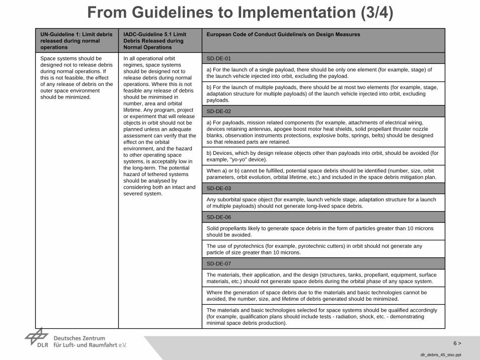
From Guidelines to Implementation (3/4)UN-Guideline 1: Limit debrisreleased during normal operations
IADC-Guideline 5.1 Limit Debris Released duringNormal Operations
European Code of Conduct Guideline/s on Design Measures
SD-DE-01
a) For the launch of a single payload, there should be only one element (for example, stage) of the launch vehicle injected into orbit, excluding the payload.
b) For the launch of multiple payloads, there should be at most two elements (for example, stage, adaptation structure for multiple payloads) of the launch vehicle injected into orbit, excludingpayloads.
SD-DE-02
a) For payloads, mission related components (for example, attachments of electrical wiring, devices retaining antennas, apogee boost motor heat shields, solid propellant thruster nozzleblanks, observation instruments protections, explosive bolts, springs, belts) should be designedso that released parts are retained.
b) Devices, which by design release objects other than payloads into orbit, should be avoided (forexample, "yo-yo" device).
When a) or b) cannot be fulfilled, potential space debris should be identified (number, size, orbitparameters, orbit evolution, orbital lifetime, etc.) and included in the space debris mitigation plan.
SD-DE-03
Any suborbital space object (for example, launch vehicle stage, adaptation structure for a launchof multiple payloads) should not generate long-lived space debris.
SD-DE-06
Solid propellants likely to generate space debris in the form of particles greater than 10 micronsshould be avoided.
The use of pyrotechnics (for example, pyrotechnic cutters) in orbit should not generate anyparticle of size greater than 10 microns.
SD-DE-07
The materials, their application, and the design (structures, tanks, propellant, equipment, surfacematerials, etc.) should not generate space debris during the orbital phase of any space system.
Where the generation of space debris due to the materials and basic technologies cannot beavoided, the number, size, and lifetime of debris generated should be minimized.
The materials and basic technologies selected for space systems should be qualified accordingly(for example, qualification plans should include tests - radiation, shock, etc. - demonstratingminimal space debris production).
Space systems should bedesigned not to release debrisduring normal operations. Ifthis is not feasible, the effectof any release of debris on theouter space environmentshould be minimized.
In all operational orbitregimes, space systemsshould be designed not to release debris during normal operations. Where this is notfeasible any release of debrisshould be minimised in number, area and orbital lifetime. Any program, projector experiment that will releaseobjects in orbit should not beplanned unless an adequateassessment can verify that theeffect on the orbital environment, and the hazardto other operating spacesystems, is acceptably low in the long-term. The potential hazard of tethered systemsshould be analysed byconsidering both an intact and severed system.

7 >
dlr_debris_45_stsc.ppt
From Guidelines to Implementation (4/4)
Today SDETES: Space Debris End-to-End Service

8 >
dlr_debris_45_stsc.ppt
Contents
From UN Space Debris Mitigation Guidelinesto Implementation
Product Assurance Requirements Tailoring Process
Space Debris Mitigation Measures – Examples uponSubjects of Analysis and Implementation

9 >
dlr_debris_45_stsc.ppt
European CoCSpace Debris
Military Standards
European Cooperation forSpace Standardization
European SpaceComponentsCooperation
Space Station & ShuttleSafety
NASA STD 8718.14
Product Assurance Requirements Tailoring Process (1/5)

10 >
dlr_debris_45_stsc.ppt
Product Assurance Requirements Tailoring Process (2/5)
11 >
dlr_debris_45_stsc.ppt
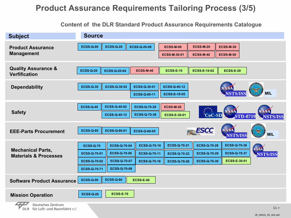
Content of the DLR Standard Product Assurance Requirements Catalogue
Software Product Assurance
Mechanical Parts, Materials & Processes
Product Assurance Management
Safety
DependabilityNSTS/ISS
Quality Assurance & Verfification
EEE-Parts Procurement
Subject Source
ECSS-Q-00 ECSS-Q-20 ECSS-Q-20-09 ECSS-M-00 ECSS-M-30ECSS-M-20
ECSS-M-50ECSS-M-30-01 ECSS-M-40
ECSS-Q-30 ECSS-Q-40-12ECSS-Q-30-02
ECSS-Q-60-11
NSTS/ISS
NSTS/ISSECSS-Q-60 ECSS-Q-60-01
NSTS/ISS
ECSS-Q-40
ECSS-Q-40-12
ECSS-M-20ECSS-Q-70-29
ECSS-Q-70-36
ECSS-Q-40-02
ECSS-E-30-01
ECSS-Q-70
ECSS-Q-70-01
ECSS-Q-70-02
ECSS-Q-70-04
ECSS-Q-70-07
ECSS-Q-70-08
ECSS-Q-70-10
ECSS-Q-70-11
ECSS-Q-70-18
ECSS-Q-70-21
ECSS-Q-70-22
ECSS-Q-70-26
ECSS-Q-70-28
ECSS-Q-70-29
ECSS-Q-70-30
ECSS-Q-70-36
ECSS-Q-70-37
ECSS-E-30-01
ECSS-Q-00 ECSS-Q-80 ECSS-E-40
ECSS-Q-20 ECSS-M-40 ECSS-E-10 ECSS-E-20ECSS-E-10-02
ECSS-Q-70-71
Mission Operation ECSS-Q-20 ECSS-E-70
MIL
MILECSS-Q-30-01
ECSS-E-10-05
ECSS-Q-20-04
ECSS-Q-60-05
ECSS-Q-70-06
STD-8719CoC-SD
Product Assurance Requirements Tailoring Process (3/5)
12 >
dlr_debris_45_stsc.ppt
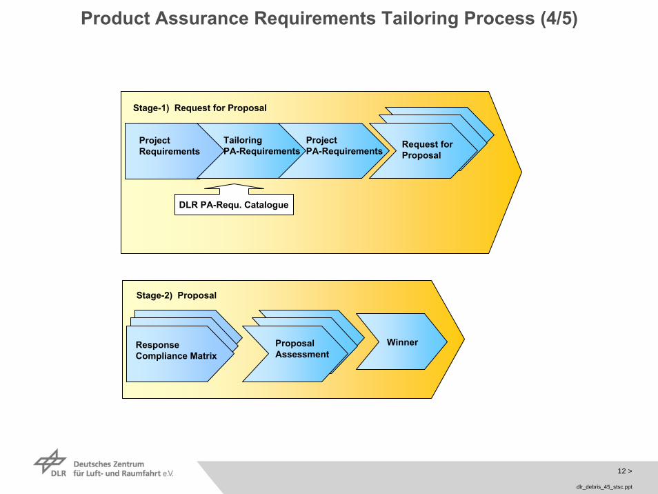
Stage-1) Request for Proposal
ProjectRequirements
TailoringPA-Requirements
ProjectPA-Requirements
Request forProposal
DLR PA-Requ. Catalogue
Stage-2) Proposal
ProposalAssessment
WinnerResponseCompliance Matrix
Product Assurance Requirements Tailoring Process (4/5)

13 >
dlr_debris_45_stsc.ppt
Stage-5) PA-Controlling
Stage-4) ContractorPA-Planning
Stage-3) Contract
Consolidation ofPA-Aktivities
Resp, Comp.Matrix
Project PA-Requ.
ConsolidatetPA-Requirements
ReviewsReportsInspectionAudits
PA-PlanConsol, Comp.MatrixProject PA-Requiremnets
ContractorPA-Plan
Consol, Comp.Matrix
Project PA-Requ.
Product Assurance Requirements Tailoring Process (5/5)

14 >
dlr_debris_45_stsc.ppt
Contents
From UN Space Debris Mitigation Guidelinesto Implementation
Product Assurance Requirements Tailoring Process
Space Debris Mitigation Measures – Examples uponSubjects of Analysis and Implementation

15 >
dlr_debris_45_stsc.ppt
Space Debris Mitigation Measures – Examples uponSubjects of Analysis and Implementation (1/7)
EnMAP (Environmental Mapping and Analysis Program)
Bus Modified OHB Bus
Instrument New Design
S/C Weight 740 kg
Orbital period ca. 98 min
Orbit inclination 97.96°, SSO
Mission lifetime 5 years
S/C Dimension 1,3m x 1,7m x 3,1m
Orbit altitude 643 km

16 >
dlr_debris_45_stsc.ppt
Guideline 1: Limit debris released during normal operations
Guideline 2: Minimize the potential for break-ups during operational phases
Guideline 3: Limit the probability of accidental collision in orbit
Guideline 4: Avoid intentional destruction and other harmful activities
Guideline 5: Minimize potential for post-mission break-ups resulting from stored energy
Guideline 6: Limit the long-term presence of spacecraft and launch vehicle orbital stages in the low-Earth orbit (LEO) region after the end of their mission
Guideline 7: Limit the long-term interference of spacecraft and launch vehicle orbital stages with the geosynchronous Earth orbit (GEO) region after the end of their mission
Time span (in year) between collisions with a space debris/meteoroids
Probability (%) of collisions with a space debris/meteoroids over 5 years
5,268 impacts per year for debris in the range of [1 µm, 1 mm], contribute mainly to surface degradation
Particle sizeParticle class
1 mm – 1 cm 1 cm – 10 cm 10 cm – 1 m 1 m – 10 m
Space Debris 14.85 737 17,230 55,503
Natural meteoroids 8.05 2,632 N/A N/A
0.2%46%Natural meteoroids
0.1%1%Requirement
0.7%29%Space Debris
1 cm – 10 m1 mm – 1 cm
Particle sizeParticle class
Impact effect on aluminium plate (Credits: European Space Agency, ESA )
Impact on HST solar array (Credits: European Space Agency, ESA )
Space Debris Mitigation Measures – Examples uponSubjects of Analysis and Implementation (2/7)
Under Investigation: Impact/Penetration Risk Analysis
17 >
dlr_debris_45_stsc.ppt
Guideline 1: Limit debris released during normal operations
Guideline 2: Minimize the potential for break-ups during operational phases
Guideline 3: Limit the probability of accidental collision in orbit
Guideline 4: Avoid intentional destruction and other harmful activities
Guideline 5: Minimize potential for post-mission break-ups resulting from stored energy
Guideline 6: Limit the long-term presence of spacecraft and launch vehicle orbital stages in the low-Earth orbit (LEO) region after the end of their mission
Guideline 7: Limit the long-term interference of spacecraft and launch vehicle orbital stages with the geosynchronous Earth orbit (GEO) region after the end of their mission
Space Debris Mitigation Measures – Examples uponSubjects of Analysis and Implementation (3/7)
Under Investigation: Impact/Penetration Risk Analysis
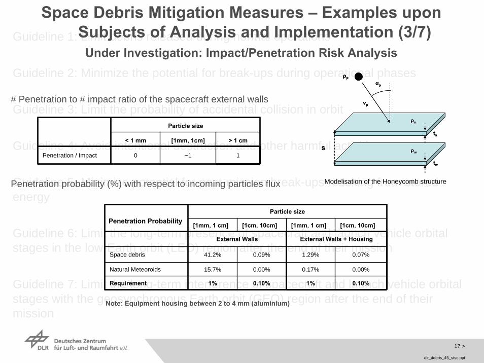
# Penetration to # impact ratio of the spacecraft external walls
Penetration probability (%) with respect to incoming particles flux
S
ts
tw
αp
vp
ρp
ρs
ρwS
ts
tw
αp
vp
ρp
ρs
ρw
Particle size
[1mm, 1 cm] [1cm, 10cm]
External Walls
41.2% 0.09%
Natural Meteoroids 15.7% 0.00% 0.17% 0.00%
0.10%1%
[1mm, 1 cm] [1cm, 10cm]
External Walls + Housing
Space debris 1.29% 0.07%
Requirement 1% 0.10%
Note: Equipment housing between 2 to 4 mm (aluminium)
Penetration Probability
Modelisation of the Honeycomb structure
1~10Penetration / Impact
[1mm, 1cm]< 1 mm > 1 cm
Particle size
18 >
dlr_debris_45_stsc.ppt
Guideline 1: Limit debris released during normal operations
Guideline 2: Minimize the potential for break-ups during operational phases
Guideline 3: Limit the probability of accidental collision in orbit
Guideline 4: Avoid intentional destruction and other harmful activities
Guideline 5: Minimize potential for post-mission break-ups resulting from stored energy
Guideline 6: Limit the long-term presence of spacecraft and launch vehicle orbital stages in the low-Earth orbit (LEO) region after the end of their mission
Guideline 7: Limit the long-term interference of spacecraft and launch vehicle orbital stages with the geosynchronous Earth orbit (GEO) region after the end of their mission
Space Debris Mitigation Measures – Examples uponSubjects of Analysis and Implementation (4/7)
Under Investigation: Re-entry Safety
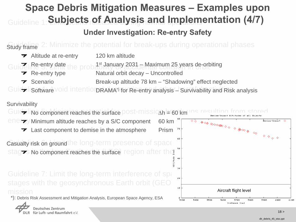
Aircraft flight levelAircraft flight level
Study frameAltitude at re-entry 120 km altitudeRe-entry date 1st January 2031 – Maximum 25 years de-orbitingRe-entry type Natural orbit decay – Uncontrolled Scenario Break-up altitude 78 km – “Shadowing” effect neglected Software DRAMA*) for Re-entry analysis – Survivability and Risk analysis
SurvivabilityNo component reaches the surface Δh = 60 kmMinimum altitude reaches by a S/C component 60 kmLast component to demise in the atmosphere Prism
Casualty risk on groundNo component reaches the surface
*): Debris Risk Assessment and Mitigation Analysis, European Space Agency, ESA

19 >
dlr_debris_45_stsc.ppt
Guideline 1: Limit debris released during normal operations
Guideline 2: Minimize the potential for break-ups during operational phases
Guideline 3: Limit the probability of accidental collision in orbit
Guideline 4: Avoid intentional destruction and other harmful activities
Guideline 5: Minimize potential for post-mission break-ups resulting from stored energy
Guideline 6: Limit the long-term presence of spacecraft and launch vehicle orbital stages in the low-Earth orbit (LEO) region after the end of their mission
Guideline 7: Limit the long-term interference of spacecraft and launch vehicle orbital stages with the geosynchronous Earth orbit (GEO) region after the end of their mission
Space Debris Mitigation Measures – Examples uponSubjects of Analysis and Implementation (5/7)
Under Investigation: Re-entry Safety, Contamination Aspects

20 >
dlr_debris_45_stsc.ppt
satellite mass 110 kg
satellite envelope 550 x 650 x 880 mm
uplink: 4 kbits/sdownlink: 2200 kbits/s
LEO
450 – 850 km
53° - sun-synchronous
3-axis stabilisation
communications /S –band
Orbit
average height
inclination
stabilisation
TET-1 (Technology Test Carrier)
payload segment 460 x 460 x 400 mm
payload mass capacity 40 kg
power consumption 0 – 20 W
nominal oper. voltage 20 , DC V
max. current 8 A
peak power consumption 160 W / 20 min (5 times per day)
System
Payload segment
Space Debris Mitigation Measures – Examples uponSubjects of Analysis and Implementation (6/7)

21 >
dlr_debris_45_stsc.ppt
Guideline 1: Limit debris released during normal operations
Guideline 2: Minimize the potential for break-ups during operational phases
Guideline 3: Limit the probability of accidental collision in orbit
Guideline 4: Avoid intentional destruction and other harmful activities
Guideline 5: Minimize potential for post-mission break-ups resulting from stored energy
Guideline 6: Limit the long-term presence of spacecraft and launch vehicle orbital stages in the low-Earth orbit (LEO) region after the end of their mission
Guideline 7: Limit the long-term interference of spacecraft and launch vehicle orbital stages with the geosynchronous Earth orbit (GEO) region after the end of their mission
Space Debris Mitigation Measures – Examples uponSubjects of Analysis and Implementation (7/7)
End-of-life Measures / Disposal (European CoC-Requirement SD-OP-03): the current baseline for TET operational orbit is820km. In order to to limit the permanent or periodic presence of TET in the protected regions to a maximum of 25 years, TET should be de-orbited to a 550 km orbit. Measures under investigation comprise following options:
Rising of drag coefficient by enlarging cross sectionApplication of a tether, both conductive (electro-magnetic drag) and non-conductive (momentum exchange) under considerationApplication of a propulsion systemApplication of a mechanical interface for cooperative docking witin the frame of a recovery mission.
Prevention Measures / Mission Related Objects (European CoC-Requirement SD-DE-02): on both satellite bus and payload level verification is ongoing to ensure that no mission related components (e.g. attachments of electrical wiring, devices retaining antennas, apogee boost motor heat shields, solid propellant thruster nozzle blanks, observation instruments protections, explosive bolts, springs, belts) will be released.
Prevention Measures / Fragmentation (European CoC-Requirement SD-DE-05): the accidental destruction probability due to an internal origin of any stored energy element (AOCS, propulsion, pressurised parts, energy storage elements - batteries, fuel cells, etc.) which should be lower than or equal to 10-4 for the operational phase is under investigation within the frame of the System-FMECA.
Prevention Measures / Materials and technologies (European CoC-Requirement SD-DE-07): analysis of materials, theirapplication, and the design (structures, tanks, propellant, equipment, surface materials, etc.) not to generate space debrisduring the orbital phase is ongoing.
End-of-life Measures / Passivation (European CoC-Requirement SD-DE-08): processes/ technical solutions to eliminate all stored energy to reduce the chance of break-up (e.g. venting or burning excess propellant, discharging batteries, relieving pressure vessels) are under investigation.

22 >
dlr_debris_45_stsc.ppt
Conclusions
The General Assembly endorsed the Space Debris Mitigation Guidelines of the COPUOS and invited Member States to implement those guidelines through relevant national mechanisms
This presentation outlined the process for the implementation of these guidelines being under development at the German Space Agency DLR
The conversion of Guidelines to implementation mechanism/s is not a trivial task
Substantial resources on different levels upon supporting documents and tools for assistance in the implementation of technical measures for space debris mitigation exist
Implementation of Guidelines at DLR is carried out by a dedicated sub-process within the frame of the Product Assurance Requirements TailoringProcess.

23 >
dlr_debris_45_stsc.ppt
Acknowledgements
Mr. Christian CHLEBEKHead of Project „EnMAP“
Mr. Wolfgang JOBIHead of Quality and Product Assurance
Mr. Michael TURKHead On-Orbit Verification Programme (OOV)
Dr. Philip WILLEMSENDeputy Head On-Orbit Verification Programme (OOV)