48-volt electrical system
TRANSCRIPT
Technical TrainingThe information contained in this manual is not to be resold, bartered, copied or transferredwithout the express written consent of BMW of North America, LLC ("BMW NA").Copyright © 2020 BMW of North America, LLC
48-VOLTELECTRICAL SYSTEM
Reference Manual
Technical�training.Product�information.
BMW�Service
48-Volt�Electrical�System.

General�information
Symbols�used
The�following�symbol�is�used�in�this�document�to�facilitate�better�comprehension�or�to�draw�attentionto�very�important�information:
Contains�important�safety�information�and�information�that�needs�to�be�observed�strictly�in�order�toguarantee�the�smooth�operation�of�the�system.
Originally�Published:�July�2019
BMW�Group�vehicles�meet�the�requirements�of�the�highest�safety�and�quality�standards.�Changesin�requirements�for�environmental�protection,�customer�benefits�and�design�render�necessarycontinuous�development�of�systems�and�components.�Consequently,�there�may�be�discrepanciesbetween�the�contents�of�this�document�and�the�vehicles�available�in�the�training�course.
The�information�contained�in�the�training�course�materials�is�solely�intended�for�participants�in�thistraining�course�conducted�by�BMW�Group�Technical�Training�Centers,�or�BMW�Group�ContractTraining�Facilities.
This�training�manual�or�any�attached�publication�is�not�intended�to�be�a�complete�and�all�inclusivesource�for�repair�and�maintenance�data.�It�is�only�part�of�a�training�information�system�designed�toassure�that�uniform�procedures�and�information�are�presented�to�all�participants.
For�changes/additions�to�the�technical�data,�repair�procedures,�please�refer�to�the�current�informationissued�by�BMW�of�North�America,�LLC,�Technical�Service�Department.
This�information�is�available�by�accessing�TIS�at�www.bmwcenternet.com.
Additional�sources�of�information
Further�information�on�the�individual�topics�can�be�found�in�the�following:
• Owner's�Manual• Integrated�Service�Technical�Application• Aftersales�Information�Research�(AIR)
The�information�contained�in�this�manual�is�not�to�be�resold,�bartered,�copied,�or�transferredwithout�the�express�written�consent�of�BMW�of�North�America,�LLC�(“BMW�NA”).
©�2020�BMW�of�North�America,�LLC
The�BMW�name�and�logo�are�registered�trademarks.�All�rights�reserved.
48-Volt�Electrical�System.Contents.1. Introduction............................................................................................................................................................................................................................................1
1.1. General....................................................................................................................................................................................................................................21.2. Bus�system�overview.......................................................................................................................................................................................31.3. System�overview.....................................................................................................................................................................................................61.4. System�wiring�diagram.................................................................................................................................................................................7
2. System�Components............................................................................................................................................................................................................92.1. Starter�motor�generator...............................................................................................................................................................................9
2.1.1. Technical�data............................................................................................................................................................................92.1.2. Installation�location.......................................................................................................................................................102.1.3. Design................................................................................................................................................................................................122.1.4. Cooling,�starter�motor�generator.............................................................................................................14
2.2. Lithium-ion�battery..........................................................................................................................................................................................152.2.1. Technical�data........................................................................................................................................................................152.2.2. Installation�location.......................................................................................................................................................162.2.3. Design................................................................................................................................................................................................172.2.4. Balancing.......................................................................................................................................................................................182.2.5. Deactivation�of�lithium-ion�battery.......................................................................................................182.2.6. Crash�deactivation..........................................................................................................................................................18
2.3. Power�Control�Unit�(DC/DC�converter)...........................................................................................................................192.3.1. Technical�data........................................................................................................................................................................192.3.2. Installation�location.......................................................................................................................................................202.3.3. Functions.......................................................................................................................................................................................202.3.4. Cooling..............................................................................................................................................................................................21
2.4. Braking�system�(DSC)................................................................................................................................................................................23
3. Functions................................................................................................................................................................................................................................................243.1. Automatic�engine�start/stop�function................................................................................................................................253.2. Load�point�increase.......................................................................................................................................................................................253.3. Assist.....................................................................................................................................................................................................................................263.4. Energy�recovery...................................................................................................................................................................................................263.5. Coasting...........................................................................................................................................................................................................................263.6. eBoost.................................................................................................................................................................................................................................27
4. Information�For�Service..............................................................................................................................................................................................284.1. Maintenance�mode.........................................................................................................................................................................................284.2. Disconnect�negative�battery�cables....................................................................................................................................284.3. Battery�exchange...............................................................................................................................................................................................284.4. External�charging...............................................................................................................................................................................................284.5. Emergency�recharging..............................................................................................................................................................................29

48-Volt�Electrical�System.Contents.5. Changelog..............................................................................................................................................................................................................................................30
48-Volt�Electrical�System.1.�Introduction.
1
The�BMW�Group�has�for�years�been�developing�a�variety�of�technologies�to�reduce�the�overallCO2 fleet�consumption.�Among�these�technologies�are�micro-hybrids,�in�which�the�measures�ofEfficientDynamics�are�implemented.�Another�important�milestone�was�the�development�of�plug-inhybrids�(PHEVs)�and�battery�electric�vehicles�(BEVs).�Now�we�are�witnessing�the�development�of�mildhybrid�technology.
The�48-Volt�System�is�being�introduced�in�the�G30�with�the�BMW�540i�and�540ix�as�of�July�2020�tobe�followed�by�G20�with�the�BMW�340i�and�340ix.�The�48-Volt�System�will�be�included�on�all�futurevehicles�equipped�with�a�B58�engine.�The�new�48-Volt�system�will�also�deliver�new�functions�whichserve�to�increase�comfort,�efficiency�and�dynamics.
The�introduction�of�mild�hybrid�technology�produces�new�functions�with�noticeable�customer�benefits:
• Reduced�CO2�emissions
Braking�energy�is�not�lost,�but�instead�electrically�recuperated.�The�combustion�engine�is�supportedin�driving�mode�and�operated�in�more�efficient�operating�conditions.�This�results�in�consumptionreductions�in�customer�operation�of�around�0.3 l/100 km.
• Improved�automatic�engine�start/stop�function�(MSA)
The�powerful�48-volt�starter�motor�generator�produces�a�noticeable�improvement�in�starting�time�ofapproximately�20%�faster�to�improved�comfort�in�terms�of�acoustics�and�vibrations�during�the�startingprocedure.�The�starting�procedures�are�now�barely�noticeable.�The�first�engine�start�of�the�day�is�doneby�the�conventional�12�volt�pinion�starter�motor.�If�the�engine�temperature�is�greater�than�60�°C�(140°F),�the�engine�will�be�started�by�the�48-volt�starter�motor�generator.
• Engine�off�coasting
In�so-called�"coasting"�the�combustion�engine�in�normal�situations�no�longer�continues�to�run�atidle�in�mild�hybrid�vehicles,�but�is�instead�switched�off�completely�and�the�drivetrain�is�decoupled�inorder�to�utilize�the�vehicle's�kinetic�energy�for�motion.�Compared�with�the�idle�coasting�function�theconsumption�advantage�can�be�further�increased�by�switching�the�combustion�engine�off.�Restartingis�virtually�delay-free�thanks�to�the�powerful�48-volt�starter�motor�generator.
• Dynamics�advantage�thanks�to�eBOOST�function
In�partial�load�operation�the�starter�motor�generator�supports�the�combustion�engine�as�an�electricalmachine.�Thanks�to�its�delay-free�power�output,�the�electrical�machine�improves�the�accelerationbuild-up,�i.e.�the�spontaneity�of�the�drive.�In�response�to�full�load�demand�the�electrical�machine�can�incertain�operating�ranges�briefly�increase�the�drive's�overall�power�by�8 kW�(10�hp).

48-Volt�Electrical�System.1.�Introduction.
2
1.1.�GeneralThe�launch�of�the�48-volt�electrical�system�is�accompanied�by�new�terminal�designations�todistinguish�it�from�the�12-volt�electrical�system.
• Terminal�B+�48 V�acquires�the�designation�terminal�40.• Terminal�B–�48 V�acquires�the�designation�terminal�41.
The�48-volt�components�starter�motor�generator�and�Power�Control�Unit�(DC/DC�converter)are�assigned�special�identification�similar�to�the�high-voltage�components.�The�reason�for�theidentification�is�as�follows:
• Compliance�with�the�ISO�standard�6469–3.
48 V�identification
The�48-volt�warning�labels�and�cables�are�now�purple�in�color�for�easy�identification�of�the�48-voltsystem.
48-Volt�Electrical�System.1.�Introduction.
3
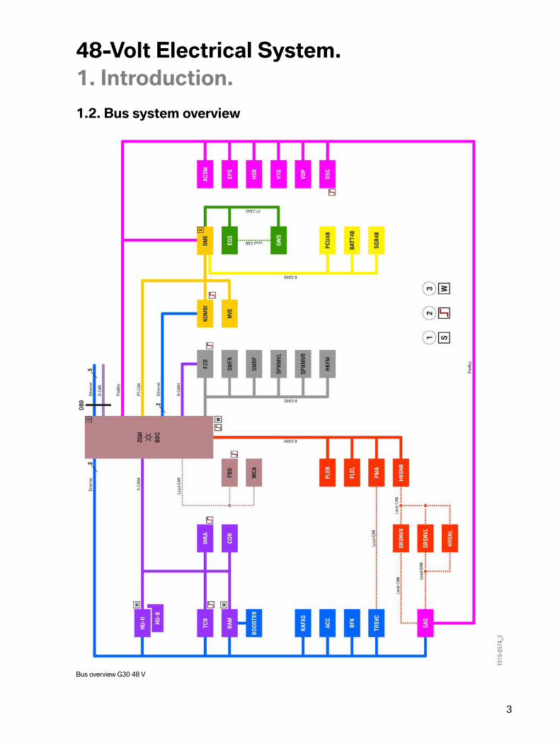
1.2.�Bus�system�overview
Bus�overview�G30�48 V

48-Volt�Electrical�System.1.�Introduction.
4
Index Explanation1 Start-up�node�control�units�for�starting�and�synchronizing
the�FlexRay�bus�system2 Control�units�authorized�to�perform�wake-up�function3 Control�units�with�hard-wired�wake-up�lineACC Active�Cruise�ControlACSM Advanced�Crash�Safety�ModuleAHM Trailer�moduleBATT48 Lithium-ion�battery�48 VBDC Body�Domain�ControllerBOOSTER AmplifierCON ControllerD-CAN Diagnosis-on-Controller�Area�NetworkDSC Dynamic�Stability�ControlELV Electronic�steering�lockEGS Electronic�transmission�controlEPS Electromechanical�Power�SteeringEthernet Cable-based�data�network�technology�for�local�data�networksFBD Remote�control�serviceFlexRay Fast,�preset�and�fault-tolerant�bus�system�for�use�in�automotive�sectorFLEL Frontal�Light�Electronics�LeftFLER Frontal�Light�Electronics�RightFZD Roof�function�centerGWS Gear�selector�switchHKFM Tailgate�function�moduleHRSNL Rear�radar�sensor�short�range�leftHRSNR Rear�radar�sensor�short�range�rightHSR Rear�axle�slip�angle�controlHU-B Head�Unit�BasicHU-H Head�Unit�HighIHKA Integrated�automatic�heating�/�air�conditioningK-CAN�2-8 Body�Controller�Area�NetworkKAFAS Camera-based�driver�assistance�systemsKOMBI Basic�instrument�clusterNVE Night�Vision�ElectronicsOBD On-board�diagnosis�(diagnostic�socket)

48-Volt�Electrical�System.1.�Introduction.
5
Index ExplanationPCU48 Power�Control�Unit�(DC/DC�converter)PMA Parking�Maneuvering�AssistantPT-CAN Powertrain�Controller�Area�NetworkPT‐CAN2 Powertrain�Controller�Area�Network�2RAM Radio�Amplifier�ModuleRFK Rear�view�cameraSAS Optional�equipment�systemSGR48 Starter�motor�generator�48 VSMFA Driver's�seat�moduleSMBF Front�passenger�seat�moduleSRSNVL Side�radar�sensor�short�range�front�leftSRSNVR Side�radar�sensor�short�range�front�rightSPNMVL Seat�pneumatics�module�front�leftSPNMVR Seat�pneumatics�module�front�rightTCB Telematic�Communication�BoxTRSVC Control�unit�for�all-round�vision�camerasVDP Vertical�Dynamic�PlatformVTG Transfer�boxWCA Wireless�charging�trayZGM Central�Gateway�Module
Expansion�to�the�48-volt�electrical�system�means�that�there�are�some�changes�in�the�bus�overview.There�is�an�additional�bus�system,�the�K-CAN�8,�to�which�the�48-volt�components�are�connected.It�is�also�connected�to�the�DME,�in�which�the�energy�management�system�is�integrated.
48-Volt�Electrical�System.1.�Introduction.
6
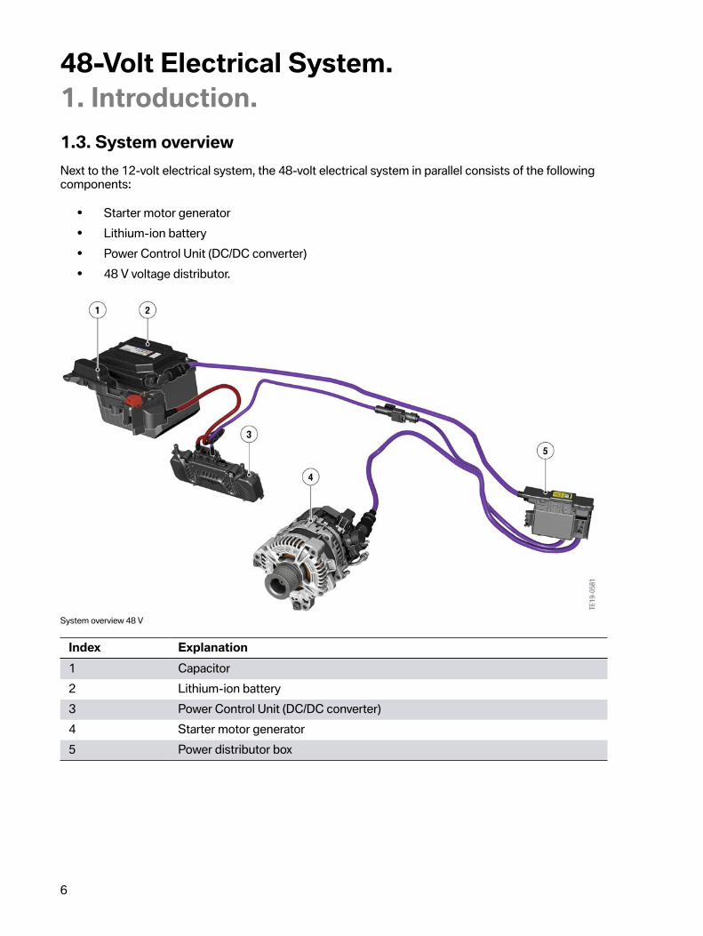
1.3.�System�overviewNext�to�the�12-volt�electrical�system,�the�48-volt�electrical�system�in�parallel�consists�of�the�followingcomponents:
• Starter�motor�generator• Lithium-ion�battery• Power�Control�Unit�(DC/DC�converter)• 48 V�voltage�distributor.
System�overview�48 V
Index Explanation1 Capacitor2 Lithium-ion�battery3 Power�Control�Unit�(DC/DC�converter)4 Starter�motor�generator5 Power�distributor�box

48-Volt�Electrical�System.1.�Introduction.
7
1.4.�System�wiring�diagram
System�wiring�diagram�48 V

48-Volt�Electrical�System.1.�Introduction.
8
Index Explanation1 Power�distribution�box�48 V2 Electric�coolant�pump,�low-temperature�coolant�circuit3 Starter�motor�generator�48 V4 Starter�motor�12 V5 Jump�start�terminal�point6 Power�distribution�box,�engine�compartment7 Lithium-ion�battery�48 V8 Power�Control�Unit�48 V�(DC/DC�converter)9 Power�distribution�box,�front�right10 Body�Domain�Controller�(BDC)11 Power�distribution�box,�luggage�compartment12 Intelligent�battery�sensor13 Battery�12 V14 Permanent�positive�distributor15 Safety�battery�terminal�SBK16 Advanced�Crash�Safety�Module�(ACSM)17 Brake�pedal�travel�sensor18 Dynamic�Stability�Control�(DSC)19 Low-pressure�sensor20 Digital�Motor�Electronics�(DME)21 Integrated�supply�module22 Electrical�transmission�oil�pump
48-Volt�Electrical�System.2.�System�Components.
9
2.1.�Starter�motor�generator
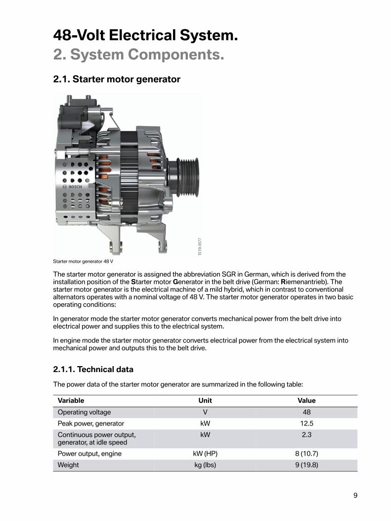
Starter�motor�generator�48 V
The�starter�motor�generator�is�assigned�the�abbreviation�SGR�in�German,�which�is�derived�from�theinstallation�position�of�the�Starter�motor�Generator�in�the�belt�drive�(German:�Riemenantrieb).�Thestarter�motor�generator�is�the�electrical�machine�of�a�mild�hybrid,�which�in�contrast�to�conventionalalternators�operates�with�a�nominal�voltage�of�48 V.�The�starter�motor�generator�operates�in�two�basicoperating�conditions:
In�generator�mode�the�starter�motor�generator�converts�mechanical�power�from�the�belt�drive�intoelectrical�power�and�supplies�this�to�the�electrical�system.
In�engine�mode�the�starter�motor�generator�converts�electrical�power�from�the�electrical�system�intomechanical�power�and�outputs�this�to�the�belt�drive.
2.1.1.�Technical�dataThe�power�data�of�the�starter�motor�generator�are�summarized�in�the�following�table:
Variable Unit ValueOperating�voltage V 48Peak�power,�generator kW 12.5Continuous�power�output,generator,�at�idle�speed
kW 2.3
Power�output,�engine kW�(HP) 8�(10.7)Weight kg�(lbs) 9�(19.8)
48-Volt�Electrical�System.2.�System�Components.
10
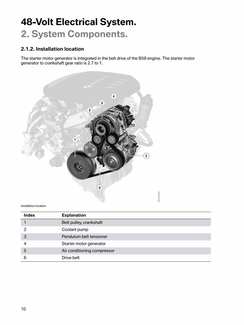
2.1.2.�Installation�locationThe�starter�motor�generator�is�integrated�in�the�belt�drive�of�the�B58�engine.�The�starter�motorgenerator�to�crankshaft�gear�ratio�is�2.7�to�1.
Installation�location
Index Explanation1 Belt�pulley,�crankshaft2 Coolant�pump3 Pendulum�belt�tensioner4 Starter�motor�generator5 Air�conditioning�compressor6 Drive�belt
48-Volt�Electrical�System.2.�System�Components.
11
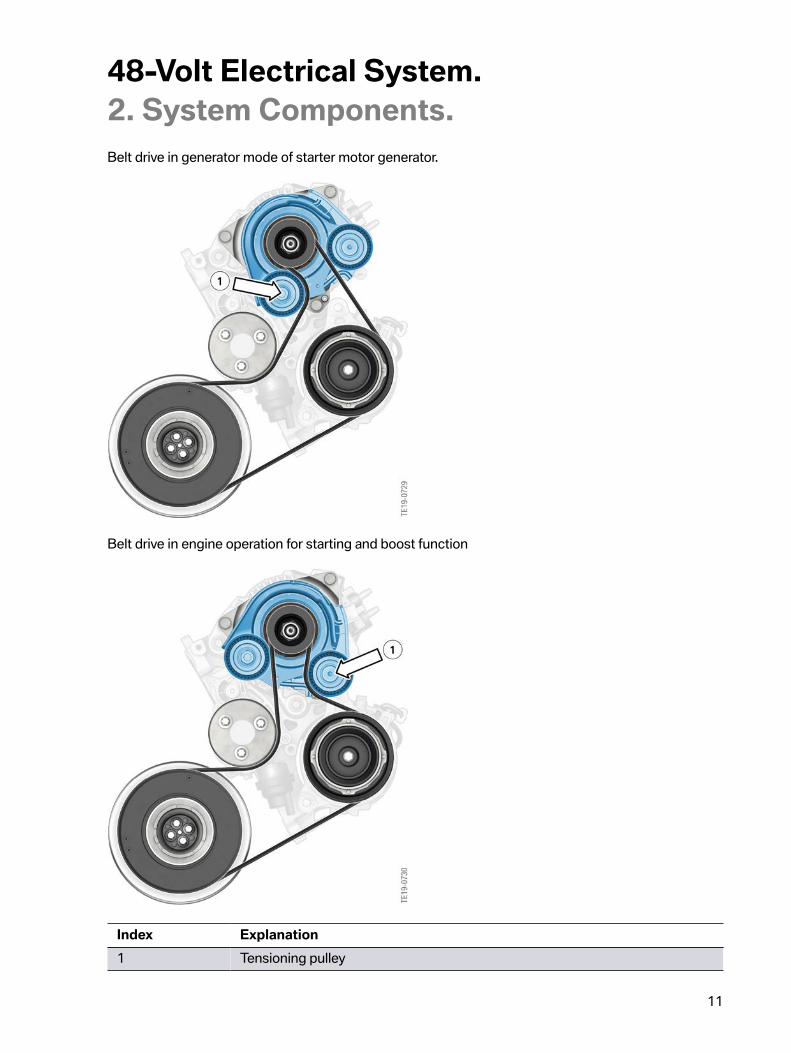
Belt�drive�in�generator�mode�of�starter�motor�generator.
Belt�drive�in�engine�operation�for�starting�and�boost�function
Index Explanation1 Tensioning�pulley

12
48-Volt�Electrical�System.2.�System�Components.2.1.3.�DesignThe�starter�motor�generator�consists�of�a�5-phase�electrical�machine,�The�power�electronics�consist of�MOSFETs,�a�microcontroller�and�a�communication�interface.�The�starter�motor�generator�has�a�bus connection�to�the�K-CAN8.
Internal�circuit,�starter�motor�generator
Index Explanation1 Housing2 Controller3 Power�transistors�(MOSFET)4 Coils5 Excitation�winding

48-Volt�Electrical�System.2.�System�Components.
13
Components�of�starter�motor�generator
Index Explanation1 Belt�pulley2 Drive�end�bracket3 Ball�bearing4 Stator5 Rotor6 Sliding�bush7 Rear�bracket8 Connecting�plate9 Controller10 Inverter11 Protective�cap
48-Volt�Electrical�System.2.�System�Components.
14
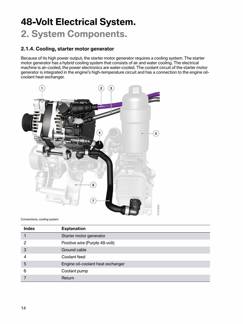
2.1.4.�Cooling,�starter�motor�generatorBecause�of�its�high�power�output,�the�starter�motor�generator�requires�a�cooling�system.�The�startermotor�generator�has�a�hybrid�cooling�system�that�consists�of�air�and�water�cooling.�The�electricalmachine�is�air-cooled,�the�power�electronics�are�water-cooled.�The�coolant�circuit�of�the�starter�motorgenerator�is�integrated�in�the�engine's�high-temperature�circuit�and�has�a�connection�to�the�engine�oil-coolant�heat�exchanger.
Connections,�cooling�system
Index Explanation1 Starter�motor�generator2 Positive�wire�(Purple�48-volt)3 Ground�cable4 Coolant�feed5 Engine�oil-coolant�heat�exchanger6 Coolant�pump7 Return

48-Volt�Electrical�System.2.�System�Components.
15
2.2.�Lithium-ion�battery
Lithium-ion�battery�48 V
The�lithium-ion�battery�is�the�energy�storage�device�for�the�starter�motor�generator's�recuperatedenergy.�In�engine�mode�it�also�makes�the�energy�available�for�the�electrical�machine.
2.2.1.�Technical�dataThe�power�data�of�the�lithium-ion�battery�are�summarized�in�the�following�table�and�relate�to�a�batterytemperature�of�35�°C�(95�°F).
Variable Value UnitNominal�voltage 44 VNumber�of�cells 20Capacity�at�35�°C�(95�°F) 11 AhCharging�capacity�at�35�°C�(95�°F) 16 kWDischarge�capacity�at�35�°C�(95�°F) 13 kWWeight 10�/�22 kg�/�lbs

48-Volt�Electrical�System.2.�System�Components.
16
2.2.2.�Installation�locationThe�installation�location�of�the�lithium-ion�battery�is�in�the�engine�compartment�on�the�firewall�at�rearright.
Installation�location,�lithium-ion�battery
48-Volt�Electrical�System.2.�System�Components.
17
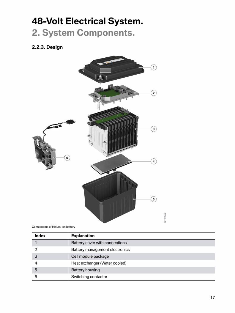
2.2.3.�Design
Components�of�lithium-ion�battery
Index Explanation1 Battery�cover�with�connections2 Battery�management�electronics3 Cell�module�package4 Heat�exchanger�(Water�cooled)5 Battery�housing6 Switching�contactor

48-Volt�Electrical�System.2.�System�Components.
18
The�cell�modules�consist�at�the�anode�end�of�nickel�manganese�cobalt�NMC.�At�the�cathode�enda�mixture�of�lithium�titanium�oxide�LTO�is�used.�The�chemical�composition�produces�an�NMC/LTOlithium-ion�battery.�The�lithium-ion�battery�operates�at�a�range�of�between�-25�°C�(-13�°F)�and�60�°C(140�°F);�the�power�is�reduced�at�temperatures�above�60�°C�(140�°F)�to�72�°C�(162�°F).�Voltages�of38 V�to�53 V�are�obtained.
2.2.4.�BalancingThe�Balancing�function�is�used�to�equalize�the�differential�voltage�of�the�individual�cells�again�in�theevent�of�unequal�discharge.�This�is�comparable�with�the�CSC�in�high-voltage�batteries.�Balancingis�performed�automatically�when�the�vehicle�is�in�sleep�mode�and�can�last�a�maximum�of�8 hours.A�maximum�3%�SoC�difference�between�the�cells�can�be�equalized�in�this�period�of�8 hours.�Theprocedure�must�be�repeated�to�compensate�greater�differences.
2.2.5.�Deactivation�of�lithium-ion�batteryTo�prevent�the�generation�of�an�electric�arc�when�working�on�the�vehicle�or�on�the�48-volt�electricalsystem�when�the�electrical�system�is�deactivated�under�load,�an�automatic�deactivation�occurs�as�soonas�the�hood�is�opened.�A�switching�contactor�which�is�designed�as�a�bi-stable�relay�is�installed�in�thelithium-ion�battery.�As�soon�as�the�Body�Domain�Controller�detects�the�hood�open�signal,�a�CheckControl�message�is�generated�and�displayed�in�the�instrument�cluster.
If�the�air-gap�contactor�is�opened,�the�12-volt�electrical�system�is�not�supported�by�the�48-voltelectrical�system.
2.2.6.�Crash�deactivationFor�safety�reasons�the�48-volt�components�lithium-ion�battery�and�Power�Control�Unit�have�a�terminal30C�(crash�terminal).�This�is�disconnected�by�the�ACSM�from�the�12 V�battery�in�the�event�of�a�crash.A�voltage�drop�at�this�terminal�results�in�an�immediate�powering-down�of�the�system.�The�DC/DCconverter�is�rapidly�powered�down�here;�there�is�no�zero-current�control�and�the�switching�contactorof�the�lithium-ion�battery�is�disconnected�under�load.�If�terminal�30C�is�inadvertently�disconnected,this�deactivation�is�regenerated�automatically�after�the�connection�is�restored;�fault�memories�in�thecomponents�document�this�disconnection.
48-Volt�Electrical�System.2.�System�Components.
19
2.3.�Power�Control�Unit�(DC/DC�converter)
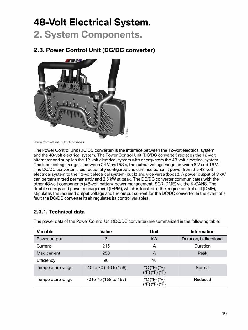
Power�Control�Unit�(DC/DC�converter)
The�Power�Control�Unit�(DC/DC�converter)�is�the�interface�between�the�12-volt�electrical�systemand�the�48-volt�electrical�system.�The�Power�Control�Unit�(DC/DC�converter)�replaces�the�12-voltalternator�and�supplies�the�12-volt�electrical�system�with�energy�from�the�48-volt�electrical�system.The�input�voltage�range�is�between�24 V�and�58 V,�the�output�voltage�range�between�6 V�and�16 V.The�DC/DC�converter�is�bidirectionally�configured�and�can�thus�transmit�power�from�the�48-voltelectrical�system�to�the�12-volt�electrical�system�(buck)�and�vice�versa�(boost).�A�power�output�of�3 kWcan�be�transmitted�permanently�and�3.5 kW�at�peak.�The�DC/DC�converter�communicates�with�theother�48-volt�components�(48-volt�battery,�power�management,�SGR,�DME)�via�the�K-CAN8.�Theflexible�energy�and�power�management�(fEPM),�which�is�located�in�the�engine�control�unit�(DME),stipulates�the�required�output�voltage�and�the�output�current�for�the�DC/DC�converter.�In�the�event�of�afault�the�DC/DC�converter�itself�regulates�its�control�variables.
2.3.1.�Technical�dataThe�power�data�of�the�Power�Control�Unit�(DC/DC�converter)�are�summarized�in�the�following�table:
Variable Value Unit InformationPower�output 3 kW Duration,�bidirectionalCurrent 215 A DurationMax.�current 250 A PeakEfficiency 96 %Temperature�range -40�to�70�(-40�to�158) °C�(°F)�(°F)
(°F)�(°F)�(°F)Normal
Temperature�range 70�to�75�(158�to�167) °C�(°F)�(°F)(°F)�(°F)�(°F)
Reduced

48-Volt�Electrical�System.2.�System�Components.
20
2.3.2.�Installation�locationThe�installation�location�of�the�Power�Control�Unit�(DC/DC�converter)�is�in�the�front�passenger�footwellunder�the�carpet�and�can�only�be�accessed�with�difficulty�in�the�event�of�an�exchange.�However,�nomaintenance�or�adjustment�work�needs�to�be�carried�out�on�Power�Control�Unit�(DC/DC�converter).
2.3.3.�FunctionsThe�Power�Control�Unit�(DC/DC�converter)�is�bidirectionally�configured�and�has�2�essential�functions:
• Buck�mode• Boost�mode
Buck�mode
In�buck�mode�the�12-volt�electrical�system�is�supplied�by�the�Power�Control�Unit�(DC/DC�converter)with�3 kW.
Electric�acceleration�mode
In�boost�mode�energy�is�transferred�from�the�12-volt�electrical�system�via�the�Power�Control�Unit(DC/DC�converter)�to�the�48-volt�electrical�system�for�the�48 V�lithium-ion�battery.�In�the�Parkingdriving�condition�the�switching�contactor�in�the�lithium-ion�battery�is�opened.�The�48-volt�electricalsystem�is�activated�during�the�terminal�change�to�the�Residing/Driving�condition.�To�be�able�toclose�the�switching�contactor�without�sparking,�it�is�necessary�to�increase�the�voltage�in�the�48-voltelectrical�system�to�the�level�of�the�48 V�lithium-ion�battery.�The�intermediate�capacitors�of�the�batterymanagement�system�are�charged�by�the�Power�Control�Unit�(DC/DC�converter).
48-Volt�Electrical�System.2.�System�Components.
21
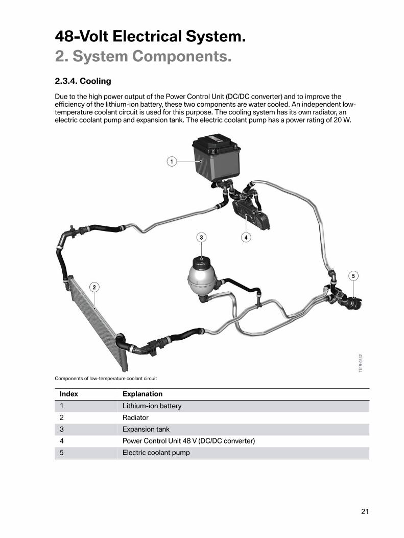
2.3.4.�CoolingDue�to�the�high�power�output�of�the�Power�Control�Unit�(DC/DC�converter)�and�to�improve�theefficiency�of�the�lithium-ion�battery,�these�two�components�are�water�cooled.�An�independent�low-temperature�coolant�circuit�is�used�for�this�purpose.�The�cooling�system�has�its�own�radiator,�anelectric�coolant�pump�and�expansion�tank.�The�electric�coolant�pump�has�a�power�rating�of�20 W.
Components�of�low-temperature�coolant�circuit
Index Explanation1 Lithium-ion�battery2 Radiator3 Expansion�tank4 Power�Control�Unit�48 V�(DC/DC�converter)5 Electric�coolant�pump
48-Volt�Electrical�System.2.�System�Components.
22
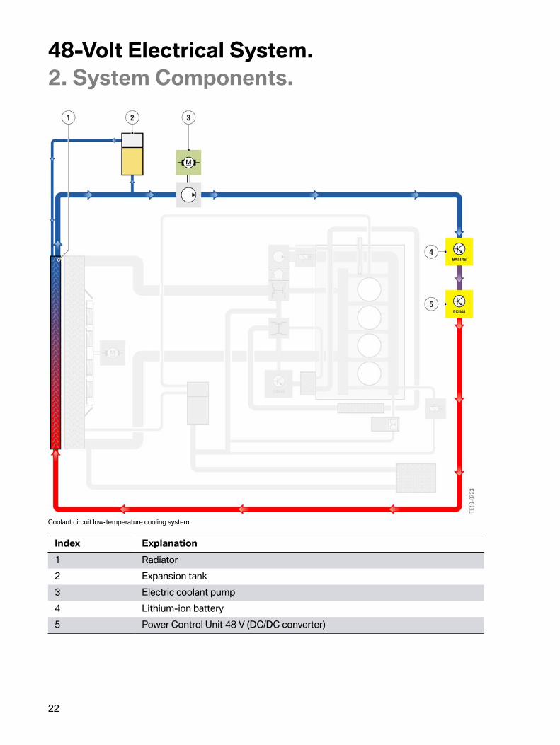
Coolant�circuit�low-temperature�cooling�system
Index Explanation1 Radiator2 Expansion�tank3 Electric�coolant�pump4 Lithium-ion�battery5 Power�Control�Unit�48 V�(DC/DC�converter)

48-Volt�Electrical�System.2.�System�Components.
23
2.4.�Braking�system�(DSC)A�special�braking�system,�as�is�also�used�in�other�PHEVs,�is�required�to�enable�the�full�recuperationpower�of�the�starter�motor�generator�to�be�used.�Decoupling�from�the�hydraulic�system�is�requiredso�that�the�customer�always�senses�the�same�brake�feel.�A�certain�vehicle�acceleration�is�alreadyobtained�as�a�result�of�the�energy�recovery.�Therefore�less�hydraulic�pressure�is�built�up�than�in�purehydraulic�braking�to�arrive�at�the�desired�acceleration.
To�detect�the�pedal�travel,�a�pedal�angle�sensor�is�installed�on�the�brake�pedal�linkage.

48-Volt�Electrical�System.3.�Functions.
24
An�overview�of�the�current�functions�of�the�48-volt�electrical�system�is�provided�below.
Overview�of�functions
Index Explanation1 Faster�and�more�convenient�engine�start2 Load�point�increase3 Assist4 Energy�recovery5 Engine�off�coasting6 eBoost
Starter�motor�generator�share
Combustion�engine�share
No�drive�power�from�starter�motor�generator�or�combustion�engine
48-Volt�Electrical�System.3.�Functions.
25
3.1.�Automatic�engine�start/stop�function
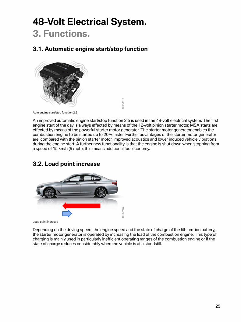
Auto�engine�start/stop�function�2.5
An�improved�automatic�engine�start/stop�function�2.5�is�used�in�the�48-volt�electrical�system.�The�firstengine�start�of�the�day�is�always�effected�by�means�of�the�12-volt�pinion�starter�motor,�MSA�starts�areeffected�by�means�of�the�powerful�starter�motor�generator.�The�starter�motor�generator�enables�thecombustion�engine�to�be�started�up�to�20%�faster.�Further�advantages�of�the�starter�motor�generatorare,�compared�with�the�pinion�starter�motor,�improved�acoustics�and�lower�induced�vehicle�vibrationsduring�the�engine�start.�A�further�new�functionality�is�that�the�engine�is�shut�down�when�stopping�froma�speed�of�15 km/h�(9�mph);�this�means�additional�fuel�economy.
3.2.�Load�point�increase
Load�point�increase
Depending�on�the�driving�speed,�the�engine�speed�and�the�state�of�charge�of�the�lithium-ion�battery,the�starter�motor�generator�is�operated�by�increasing�the�load�of�the�combustion�engine.�This�type�ofcharging�is�mainly�used�in�particularly�inefficient�operating�ranges�of�the�combustion�engine�or�if�thestate�of�charge�reduces�considerably�when�the�vehicle�is�at�a�standstill.
48-Volt�Electrical�System.3.�Functions.
26
3.3.�Assist
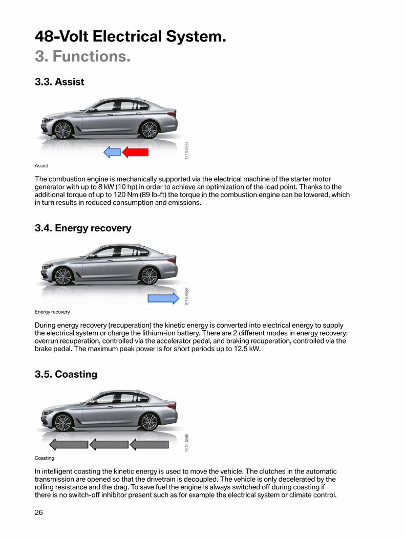
Assist
The�combustion�engine�is�mechanically�supported�via�the�electrical�machine�of�the�starter�motorgenerator�with�up�to�8 kW�(10�hp)�in�order�to�achieve�an�optimization�of�the�load�point.�Thanks�to�theadditional�torque�of�up�to�120 Nm�(89�lb-ft)�the�torque�in�the�combustion�engine�can�be�lowered,�whichin�turn�results�in�reduced�consumption�and�emissions.
3.4.�Energy�recovery
Energy�recovery
During�energy�recovery�(recuperation)�the�kinetic�energy�is�converted�into�electrical�energy�to�supplythe�electrical�system�or�charge�the�lithium-ion�battery.�There�are�2�different�modes�in�energy�recovery:overrun�recuperation,�controlled�via�the�accelerator�pedal,�and�braking�recuperation,�controlled�via�thebrake�pedal.�The�maximum�peak�power�is�for�short�periods�up�to�12.5 kW.
3.5.�Coasting
Coasting
In�intelligent�coasting�the�kinetic�energy�is�used�to�move�the�vehicle.�The�clutches�in�the�automatictransmission�are�opened�so�that�the�drivetrain�is�decoupled.�The�vehicle�is�only�decelerated�by�therolling�resistance�and�the�drag.�To�save�fuel�the�engine�is�always�switched�off�during�coasting�ifthere�is�no�switch-off�inhibitor�present�such�as�for�example�the�electrical�system�or�climate�control.
48-Volt�Electrical�System.3.�Functions.
27
Coasting�is�available�in�COMFORT�and�ECOPRO�modes�after�the�accelerator�pedal�is�released.�InCOMFORT�mode,�in�contrast�to�ECOPRO�mode,�the�onset�of�coasting�occurs�only�when�an�economicdriving�style�is�detected,�i.e.�the�accelerator�pedal�has�been�released�slowly.�Coasting�takes�placebetween�25–160�km/h�(15–100�mph).�In�both�driving�modes�anticipatory�function�intelligencesprovides�support�in�the�efficient�application�of�the�coasting�function.�Function�intelligence�usesmap�data�and�information�on�the�vehicle�in�front�to�detect�deceleration�situations�and�to�deceleratein�energy�recovery�mode�instead�of�in�coasting�mode.�If�the�vehicle�is�to�be�accelerated�again,�thecombustion�engine�is�started�via�the�starter�motor�generator�when�the�accelerator�pedal�is�pressureand�the�clutches�in�the�automatic�transmission�are�closed.�An�additional�electric�transmission�oil�pumpensures�that�the�transmission�is�lubricated�to�the�requisite�level�during�the�engine�off�phases.
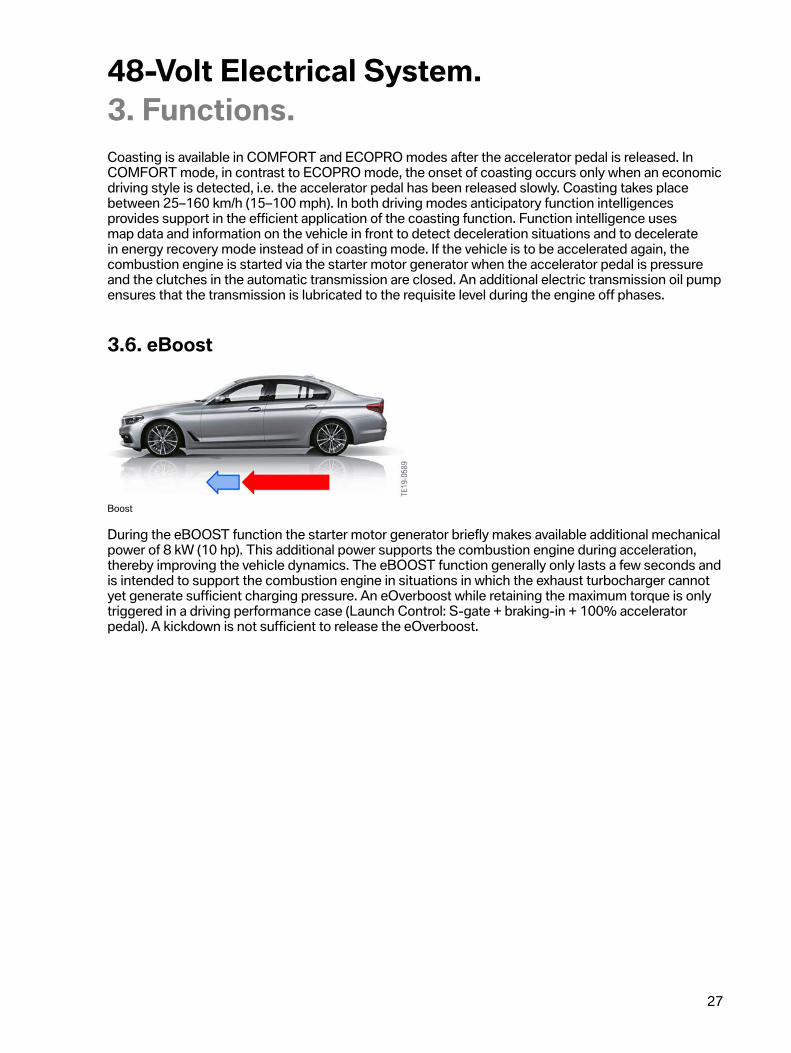
3.6.�eBoost
Boost
During�the�eBOOST�function�the�starter�motor�generator�briefly�makes�available�additional�mechanicalpower�of�8 kW�(10�hp).�This�additional�power�supports�the�combustion�engine�during�acceleration,thereby�improving�the�vehicle�dynamics.�The�eBOOST�function�generally�only�lasts�a�few�seconds�andis�intended�to�support�the�combustion�engine�in�situations�in�which�the�exhaust�turbocharger�cannotyet�generate�sufficient�charging�pressure.�An�eOverboost�while�retaining�the�maximum�torque�is�onlytriggered�in�a�driving�performance�case�(Launch�Control:�S-gate�+�braking-in�+�100%�acceleratorpedal).�A�kickdown�is�not�sufficient�to�release�the�eOverboost.

48-Volt�Electrical�System.4.�Information�For�Service.
28
4.1.�Maintenance�modeDuring�servicing�in�the�workshop�the�maintenance�mode�is�initiated�as�soon�as�the�vehicle�hood�isopened.�As�a�result�the�48-volt�electrical�system�is�powered�down�and�remains�powered�down�untileither�the�hood�is�closed,�a�switch�to�driving�is�made�or�an�external�battery�charge�is�detected.
Display�in�the�instrument�cluster.
4.2.�Disconnect�negative�battery�cablesDuring�various�servicing�work,�such�as�for�example�working�on�the�airbag�system�or�exchangingcontrol�units,�it�is�necessary�to�disconnect�the�ground�cables�of�the�batteries.�A�specific�proceduremust�be�followed�for�the�48-volt�electrical�system.�First,�disconnect�the�ground�cable�of�the�48-voltbattery.�Then�the�deactivation�of�the�system�must�be�confirmed�in�the�instrument�cluster.�Finally,disconnect�the�12 V�ground�cable.
4.3.�Battery�exchangeAfter�the�lithium-ion�battery�is�exchanged,�this�must�be�registered�in�the�diagnostic�system.Furthermore,�it�is�necessary�to�execute�a�service�function�since�the�supplied�battery�is�in�a�transportmode�and�the�air-gap�contactor�cannot�be�closed.
4.4.�External�chargingExternal�charging�of�the�vehicle�is�still�performed�via�the�12 V�jump�start�terminal�in�the�enginecompartment.�Primarily,�this�is�intended�to�charge�the�12-volt�battery.�When�a�threshold�ofapproximately�50%�SoC�of�the�12-volt�battery�is�exceeded,�the�48-volt�battery�is�likewise�charged.To�this�end�the�system�is�powered�up�after�a�defined�charging�voltage�has�been�exceeded�andplaced�in�boost�mode�(12 V�to�48 V).�The�lithium-ion�battery�can�be�externally�charged�in�the�drivingcondition�Residing,�stationary�functions�and�PAD.�External�charging�only�functions�if�the�hood�hasbeen�detected�as�being�open.�With�the�vehicle�in�sleep�mode�the�IBS�detects�the�external�batterycharge�and�wakes�the�vehicle�up,�whereupon�the�48-volt�electrical�system�is�powered�up.�Externalcharging�is�terminated�when�the�charging�voltage�drops�again�or�the�48-volt�battery�is�fully�charged.

48-Volt�Electrical�System.4.�Information�For�Service.
29
4.5.�Emergency�rechargingThe�emergency�charging�function�is�implemented�along�roughly�similar�lines�to�the�PHEV.�Here,�whenthe�12 V�battery�drops�below�a�critical�threshold�value�while�the�vehicle�is�in�sleep�mode,�the�vehicle�iswoken�up�and�recharged�from�the�energy�of�the�48-volt�battery.�The�conditions�are�currently:�Vehiclebefore�going-to-sleep�process�greater�than�12 V�for�at�least�1 minute�(arming�of�the�IBS�for�thisfunction),�vehicle�goes�to�sleep�and�the�voltage�drops�below�12 V.�Recharging�is�generally�conducteduntil�the�48-volt�battery�reaches�a�certain�threshold�value�or�a�timeout�has�expired.�The�vehicle�thengoes�to�sleep�again.

48-Volt�Electrical�System.5.�Changelog
30
Index Section Summary�of�Changes Date1 1�Introduction Added�“The�48-Volt�System�will�be�included�on�all
future�vehicles�equipped�with�a�B58�engine.”�to�thesecond�paragraph.
7/24/20

