4851 4855.output
TRANSCRIPT

* GB785258 (A)
Description: GB785258 (A) ? 1957-10-23
Products for preparing the large intestine for x-ray photography and methodof manufacturing the same
Description of GB785258 (A) Translate this text into Tooltip
[75][(1)__Select language] Translate this text into
The EPO does not accept any responsibility for the accuracy of data and information originating from other authorities than the EPO; in particular, the EPO does not guarantee that they are complete, up-to-date or fit for specific purposes.
COMPLETE SPECIFICATION Products for preparing the Large llntest:ne for XRay Photography and method of FDaRnMf ctllring the same We, at FERROSAN, a Swedish Company, of 35, Celsiusgatan, Malmo, Sweden, do hereby declare the invention, for which we pray that a patent may be granted to us, and the method by which it is to be performed, to be particularly described in and by the following statemenu: This invention relates to products for preparing the large intestine for X-ray photography and method of manufacturing the same. Heretofore, the technique of X-ray diagnosis had not advanced so far as to allow discovery of cancer tumours of minor sizes. As it is a general experience that an early discovery of cancerous tumours is extremely important it is highly desirable to improve the possibilities of early X-ray diagnosis. One of the most essential conditions for obtaining good roentgenograms is that the patient's intestine be cleaned efficiently. Treatment with the known laxatives and water enemata have proved unsatisfactory for preparing the intestine for this purpose, a fact well known to physicians, surgeons and roentgenologists. According to the invention, a product for preparing the large

intestine for X-ray photography comprises a laxative agent-preferably one that is capable of causing Holzknecht's long movements of the bowels-and an agent having a tanning effect and/or an effect of reducing the mucus secretion of the intestinal walls, for instance tannin or other tanning agents of vegetable origin such as mimosa, chestnut, quebracho, or synthetic tanning agents, or aluminium sub acetate. The effect of administering this product is not only that the intestine is emptied very efficiently but also that the intestine is prepared in such a manner as to permit an increased adhesion of the X-ray contrast medium to the inner intestinal walls. When a preparation according. to the invention has been administered and subsequently air is blown into the intestine the walls of the latter will be lined with an extremely thin, wall paper4ike coating. In this manner, even very small tumours will come out in the roentgenogram. Experiments made at the Malm5 Institute of Pathology have - shown that tumours which were so small that they could be discovered only with the aid of a magnifying glass were all benign, but the doctors are inclined to believe that some of these small tumours grow and become malignant. It is therefore of extreme importance to find such tumours in their very early stages. With the aid of the products according to the invention it has been possible to discover tumours of very small sizes down to pinhead size- which has been totally impossible heretofore. In the department for X-ray diagnosis at the Malmo General Hospital more than 2,000 patients were examined with the aid of the products of the present invention. In 12% of these cases there were found tumours of such small size that they would not have been discovered without the aid of the new product. Up to now, about one third of these tumours have been removed by operation, and a histological examination has shown that about 12% of these small neoplasms had a cancerous character while 40% were found to have a definitely precancerous character. This shows the great importance of the present invention for an early discovery of cancer diseases in the colon, and from a statistical report published by American Life Insurance Company in 1945 it appears that 17% of all deaths due to cancer are caused by malignant tumours in the large intestine including the rectum. In those cases in which it has been possible, with the aid of the new products according to the present invention, to discover this type of neoplasms in the large intestine and the patients are not suffering from them in any way, new X-ray examinations are made every few months and if the neoplasms are then found to be growing they are extirpated, as a preventive measure. In

this manner, precancerous and non-invasive tumours have been removed by operation be fore they have caused any, or at least any macroscopically detectable, metastases. It is therefore believed that the invention may allow a kind of prophylaxis of cancer occurring in the large intestine. The products of the present invention are used in the form of enemata. More particularly, it is necessary to apply two enemata, i.e. the first one comprising a solution of a product according to the invention but not containing an X-ray contrast medium, and then, when the intestines have been emptied and thus liberated from excrements, there follows a second enema comprising a suspension of an X-ray contrast medium suitable for ingestion, such as barium sulphate, together with a product according to the invention. In this manner it is possible to produce very smooth and adhesive coatings of barium sulphate on the intestinal wall due to which it is possible to discover in the roentgenogram even very small neoplasms in the large intestine such as would not have been visible without the use of the new preparations. One method of preparing the products of the present invention is simply to mix together in one product the laxative agent, preferably one capable of causing Holzkneckt's long bowel movements, with the aforesaid substances having a tanning effect and/or an effect reducing the mucus secretion of the large intestine. They are mixed together in proportions such that the amount of the latter substances is at least 20 times and preferably 100-200 times that of the laxative agent. Thus, the product suitably contains 0.5 to 5% by weight of the laxative agent. If the product is prepared by the preferred method of the invention, which will be described below, it is even sufficient to use a still smaller proportion of laxative agent, so that the amount of the substance having a tanning effect and/or an effect of reducing the mucus secretion of the large intestine may be more than 200 times and even 500 to 1000 or more times greater than the amount of laxative. Among such substances having a tanning effect and/or an effect reducing the mucus secretion of the large intestine, tannin has been found to be particularly suitable, although also other substances may be employed, for instance other substances of vegetable origin such as mimosa, chestnut and quebracho, and also synthetic tanning agents and aluminium subacetate. Suitable laxative agents capable of producing Holzknecht's long movement are in the first place certain isatin derivatives, for instance 3,3 -bis(p-acetoxyphenyl)-oxindole (also known as "diacetyl diphenol isatin" and sold under the Registered Trade Mark "Isacen") and -pyridyl-di-(P-hydroxyphenyl)-methane and the esters thereof, especially > .-pyridyl-di(p- acetoxyphenyl)-methane.

The products of the invention are used in the form of enema solutions. For this purpose they are dissolved in water of body temperature in an amount such that 1 litre of the solution will contain, for instance, 5 gms of tannin and 25 mgms of the laxative agent. An enema containing an X-ray contrast material is made with a barium sulphate suspension of the type common for X-ray purposes, for instance with Philip's tester 7.5, to which the product according to the present invention is added to give the relative proportions of tannin and of laxative agent given above. The preferred method of the present invention, referred to above is designed to increase the rate at which the product may be dissolved in water. The laxative component, particularly, is difficultly soluble in water and is often not dissolved completely. According to this preferred method, the dissolving rate of the preparations is increased by first dissolving both components together in a mutual solvent whereupon the solution is evaporated and the residue dried. Solvents suitable for this purpose are organic solvents which are miscible with water, for instance acetone, methanol, ethanol, methylal, ethylene glycol monomethyl ether and dioxan, or mixtures of these solvents. From practical experiments it has been found to be particularly suitable to dissolve 2.60 gms of the laxative component and 100 gms of the tanning component in 100 gms of solvent. The solvent is removed by evaporation to dryness which may be effected by spray drying. Despite this drying, a certain amount of solvent is retained in the product. The resultant product which contains the laxative agent in high concentration may later be admixed with for instance a twelve times greater amount of the tanning substance to thus provide a product containing 20 mgms of laxative agent per 10 gms of tanning agent When such a product is used later, it will be found that its laxative component dissolves rapidly, partly because it has been converted to a finely divided condition and partly because it has in certain cases probably formed a solvate with the solvent. Presumably this is also why, in the preparations produced according to the preferred method of the present invention, it has been found fully sufficient to use only a comparatively small amount of the laxative. While in the products produced by simply mixing the components together it is desirable to employ 0.5 , of the laxative it has been found sufficient to give the preparations produced according to the aforementioned method a content of laxative agent amounting to only about 0.2 o by weight of the product. When produced according to the preferred method of the present invention, the products have a dry feel despite the fact that they contain a certain amount of the solvent employed. The evaporation to dryness, or at least the latter part, is preferably
carried out under mild conditions, e.g. at 20--60"C. in vacuo unless it is effected by spray drying. The invention is further illustrated by the following example: 2.60 gms of cc-pyridyl-di-(p-acetoxyphenyl)- methane are dissolved in 100 cc acetone. To this solution are then added 100 gms of tannin (Chinese tannin according to the Swedish Pharmacop ia, 11th edition), with stirring and heating on a water bath. A part of the solvent is first removed by boiling, and the resulting viscous mass is then evaporated to dryness in vacuo at 20"C. for one day. The crust which is then formed is pulverized. The mixture thus obtained (105 gms) contains 5.0% by weight of acetone. It is admixed with 1197.6 gms of tannin and ground, to thus provide a product of the following composition: 20 mgms. & -pyridyl-di(p-acetoxyphenyl) - methane per 10 gms. of Tannin (with 0.42% acetone); Similar products have been obtained in the same way with other solvents and other laxatives, as will be seen from the below Table in which "152-2" means -pyridyl-di-(p-acetoxy- phenyl)-methane, "AFI" means 3,3-bis(pWacetoxyphenyl)- oxindole, and "DFI" means 3,3 -bis(p-hydroxyphenyl)- oxindole (also known as "diphenol isatin"). TABLE cc of Solvent Employed per Amount of 2.60 gms of Solvent Solvent Laxative Laxative Component Retained in Method of Component and 100 gms of the Product Drying Tannin Acetone 152-2 100 5.0 20 C. Vacuum 152-2 100 4.0 60 AFI 100 1.2 60 DFI 100 2.9 60 - *) 100 3.9 60 Methanol 152-2 90 3.7 20 " 152-2 90 2.2 50 " 152-2 90 2.3 60 " -*) 90 1.7 60 Ethanol 152-2 100 4.0 20 " 152-2 100 4.1 50 " 152-2 100 4.7 60 ,, " AFI 100 2.4 60 DFI 100 2.4 60 DFI 100 4.8 60 ,,

- - *) 120 6.8 Spray Drying at 120 C. Methylal 152-2 70 6.5 20 ,, Vacuum " 152-2 70 6.3 60 - *) 70 7.4 60 Dioxan 152-2 90 16.3 20 " 152-2 90 16.3 50 " 152-2 90 19.9 60 ,, - *) 90 23.5 60 ,, Ethylene glycol 152-2 120 - Spray Drying monomethyl ether at 175 C. *) In these tests the solutions contained only tannin and no laxative components.
* Sitemap * Accessibility * Legal notice * Terms of use * Last updated: 08.04.2015 * Worldwide Database * 5.8.23.4; 93p
* GB785259 (A)
Description: GB785259 (A) ? 1957-10-23
Control coupling
Description of GB785259 (A)
PATENT SPECIFICATION Inventor: GEORGE JOHN MUCHER Date of application and filing Complete Specification: Dec 5, 1955. No 34747/55. B y2 Complete Specification Publlghed: Oct23, 1957. Index at acceptance:-Class 80 ( 2), 52 (B 2: E: H). International Classification:-FO 6 d. COMPLETE SPECIFICATION Control Coupling We, CLAROSTAT MFG Co, INC, a Corporation organised and existing under the laws of the State of New York, United States of America, located at Washington Street, Dover, State of New Hampshire,

United States of America, do hereby declare the invention, for which we pray that a patent may be granted to us, and the method by which it is to be performed, to be particularly described in and by the following statement:- This invention relates to a structurally and functionally improved coupling and especially a coupling to be used in connection with electrical controls such as potentiometers, variable resistances, switches, etc, suitable to rotary as well as push-pull operation or the combination thereof. It is a primary object of the invention to furnish a coupling structure by means of which a workman assembling an electrical apparatus may select an operating rod or shaft of desired dimensions and properly connect that shaft to the operating member of the control with the expenditure of minimum effort and time without the necessity of employing tools or locking accesssories, or employing an involved technique. Another object is that of furnishing a coupling structure which lends itself to ready application in installations where high xoltage potentials are involved or where spacing the control unit in relation to the mounting is desired for any other reason; the teachings of the present invention permitting of the support and operation of the unit to be controlled with the elimination of substantially all current leakage. An additional object is that of providing structure of this nature which will include simple designs involving parts capable of quantity production at minimum costs and in which, moreover, these parts may be coupled by relatively unskilled labor. With these and other objects in mind reference is had to the attached sheet of drawings illustrating practical embodiments lPrice 3 s 6 d l of the invention and in which: Fig 1 is a partly sectional side view of one form of control coupling; Fig 2 is a transverse sectional view taken 50 along the line 2-2 and in the direction of the arrows as indicated in Fig 1; Fig 3 is a fragmentary sectional plan view taken along the line 3-3 and in the direction of the arrows as also indicated in Fig 1, 55 Fig 4 is a view similar to Fig 3 but showing an alternative form of structure; and Fig 5 is a view similar to Fig 1 but showing a still further arrangement of the parts. In these views the reference numeral 10 60 indicates the casing or housing of the control to be operated and from which terminals 11 conveniently extend This control may comprise a rheostat, a potentiometer, a switch, etc In any event it will usually include a 65 rotor assembly (not shown) connected to an operating member 12 rotatable within a threaded bushing 13 When the member 12 is turned

the control will be operated A nut 14 is mounted upon the threads formed on 70 the outer face of bushing 13 and engages against the face of a panel 15 and provided with an opening of a diameter such that the bushing 13 may extend through the same so that the control is properly mounted 75 The member 12 is formed with a recess 16 which adjacent its inner end may be circular in section Portions of the member 12 extend outwardly as indicated at 17 to a point beyond the end of bushing 13 These por 80 tions are formed with an annular groove 171 which is interrupted by the slot defined by portions 17 and disposed immediately adjacent the outer edge of the bushing 13 This groove receives a locking element preferably 85 in the form of a ring or washer 18 of resilient material having a C-shape With this washer in position it is apparent that axial inward movement of member 12 with respect to bushing 13 is prevented although the parts 90 may be freely rotated with respect to each other The space between the forward end portions 17 of member 12 should be noncircular in outline so as to cooperate with the similarly formed faces of an operating shaft. As shown, the space between the extended 3 portions is preferably in the form of a transverse slot communicating with the recess 16. Also as shown the outer edges of the extended portion 17 are preferably bevelled so that an operator may readily force the washer 18 in an axial direction and towards unit 10 in order to position the washer within the groove formed in member 12 So positioned it will remain until it is forcibly dislodged by employing a suitable instrument to effect this result. It is desirable in connection with controls to produce them with the rotary member 12 terminating adjacent the outer end of bushing 13 Thereupon these controls are fitted with an operating shaft embodying length and other characteristics corresponding to those desirable or necessary for the apparatus to which the control is applied Heretofore this result has been achieved by providing the assembly of parts and connecting the rotary member of the control with the operating shaft This connection has involved one of a number of different expedients All of these have necessitated a painstaking association and connection of the parts requiring the use of tools Such connection has also provided a coupling which might accidentally loosen or completely disconnect in the subsequent use of the apparatus All of these difficulties are overcome by the present teachings. Thus, as in Figs 1, 2 and 3, an operating shaft 19 is provided which has at its connecting end an extended portion 20 of a diameter such that it may move in guiding relationship with the walls of the recess 16 and freely enter the latter Intervening the main body 19 of the shaft and the extended portion 20 is a flattened part 201 having a width substantially equal to the spacing of the extended portions 17
Therefore, positioned between these portions it will completely fill the intervening transverse slot at the outer end of member 12 The outer edges of this flattened portion are defined by angularly extending surfaces 21 which provide in aggregate a wedge or cam Intervening these edges and the main body 19 of the shaft is a groove 22 which has a width such that it may receive the ring The point of juncture of the reduced inner portion of the shaft and its main body is conveniently defined by transversely extending shoulder portions 23 It is, of course, apparent that shaft 19 may be provided in various lengths and diameters or cross-sectional configurations and of any desired materials Preferably, however, it will in the embodiment shown in Figs 1 to 3 be of metal. Before or after the control unit 10 has been mounted upon a panel or support 15 an operator may select a shaft having the desired characteristics and simply introduce the inner end 20 of the same into the space between the extended portions 17 With the 70 flattened surfaces or portions of the shaft aligned with the slot between the extended parts 17 continued inward thrust may be exerted upon the shaft This will result in the inclined edge portions 21 bearing against the 75 inner edges of the ring or retaining member 18 and expanding the latter This action will continue until groove 22 is aligned with that retaining member At that instant and due to the natural resiliency of the washer or 80 its equivalent it will snap into the groove 22 So positioned it is apparent that it will function as a latch or lock to retain shaft 19 against withdrawal and with the side faces of its flattened portions in intimate contact 85 with the adjacent surfaces of the operating member 12 and its shoulders 23 in engagement with the outer end of that member. During the expanding operation of washer 18 the latter will not be displaced with respect 90 to the groove of member 13 in that it will in effect be enlarged only in line with the transverse slot in that member The end edge of flattened part 201 will bear firmly against the base of the slot in member 12 95 when the shaft is mounted Also, under these circumstances, the edges defining shoulder portions 23 will simultaneously bear against the end surfaces of member 12. With the side edges of the flattened part 20 '100 rotatably engaging the bore of bushing 13, shaft 19 is properly supported That support is even further assured with the extending portion 20 bearing against the surface of recess 16 105 With the parts operated in this manner and shifted to the positions as shown in the figures under consideration it is apparent that the operating shaft is retained against rotary or axial movements with respect to the 110 rotary member 12 Therefore, when shaft 19 is rotated through a pre-determined arc, member 12 will be similarly oscillated The operating shaft 19 will also be supported

in axial alignment with shaft 12 and will there 115 fore extend in a desired manner from the support 15 With the parts so positioned an operating knob (not shown) may conveniently be attached to shaft 19 and the coupling and operative association of the parts of 120 the assembly will now be completed As afore brought out, the control will normally be of the rotary type However, it is apparent that the foregoing teachings might be applied to a control involving a push pull 125 operation or a unit involving such an operation plus a rotation of its parts. Controls such as those herein contemplated are frequently employed in circuits involving high voltage Under these circum 130 785,259 through the bore of the sleeve extension 33. Thereupon by continued axial movement and with the flattened portion 27 aligned with respect to the slot between the extended portions 17, it will be thrust into position to a 70 point where its inclined edges 29 wedged against ring 18 to expand the latter so that groove 28 receives the ring and the outer faces of its base 26 bear against the outer end edges of bushing 13 Of course the insulat 75 ing shaft 24 need not necessarily be used with a spacing tube 31; this having been shown in Fig 5.
* Sitemap * Accessibility * Legal notice * Terms of use * Last updated: 08.04.2015 * Worldwide Database * 5.8.23.4; 93p
* GB785260 (A)
Description: GB785260 (A) ? 1957-10-23
Improvements in or relating to cardboard cases
Description of GB785260 (A)
COMPLETE SPECIFICATION Improvements in or relating to Cardboard Cases

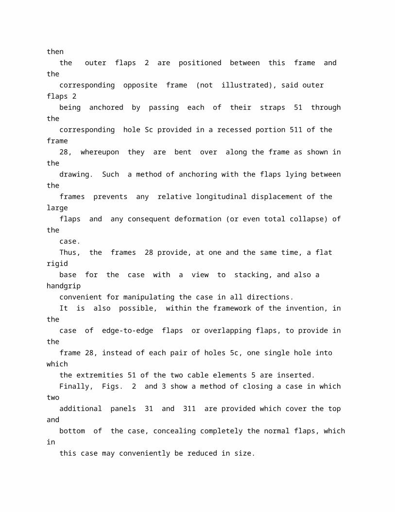
I, ROBERT THIOLAT, a French Citizen, of 24, Rue Spontini, Paris 16 , France, do hereby declare the invention, for which I pray that a patent may be granted to me, and the method by which it is to be performed, to be particularly described in and by the following statement: The present invention is concerned with improvements relating in general to cardboard cases, and more particularly to cardboard cases commonly employed for the packaging and transport of articles such as fruit, early vegetables and the like, such cases being closed above and below by panels or flaps. The main object of the invention is to provide a system whereby these panels or flaps can be rapidly and securely fixed. According to the invention, I provide in or for a collapsible cardboard case of the type capable of being dosed above and below by panels or flaps, closure means adapted to secure said panels or flaps in closed position comprising at least one thin flexible cable element passing through at least one bore provided along a free longitudinal edge of a panel or flap and adapted to be anchored at any convenient point along its length to the case. The method of anchoring the cable element to the case may vary according to the nature of the cable element in question. If the cable element is of wire, it will be advantageous to provide at the extremity of each element an eyelet, strap, or flat head, which may, for example, be nailed to a small board, rod or frame affixed to one side, or to a corner post of the tray or case, or even simply to pass the end of the cable element through a transverse bore provided for this purpose in the board, post or frame, and to bend over or twist the end of said cable element protruding beyond said bore; if the cable element is of fibrous. or synthetic cord, it may be possible to provide one single cable for all cable edges and to fix this cable to buttons, hooks or eyelets provided at appropriate points on the walls of the case or tray. Other inventive features will appear in the course of the description which will now be given with reference to the accompanying drawings, in which two embodiments of the invention are shown by way of example. In the drawings: Fig. 1 is a part-view in perspective of a case with flaps equipped in accordance with the invention; Fig. 2 is a part-view in perspective of a case closed by additional panels attached thereto, and Fig. 3 is a diagrammatic section of Fig. 2 at the plane VI-VI. Fig. 1 shows part of a case with flaps equipped in accordance with the invention; for the sake of clarity, one of the outer flaps 2 is shown open, the other closed. Thus, part of the inner flaps 3 can be seen,

both of which are closed. Each of the flaps 2 is provided along its free longitudinal edge with a bore 4 along which a cable 5 passes, the terminal straps of said cable serving to anchor the flaps when placed in position (see the right-hand flap in Fig. 1). A frame 28 (of wood or equivalent rigid material) is secured (glued, stapled, etc.) to each end panel 11 (only one of these is seen in the drawing). When the case is being closed, the inner flaps 3fez, then the outer flaps 2 are positioned between this frame and the corresponding opposite frame (not illustrated), said outer flaps 2 being anchored by passing each of their straps 51 through the corresponding hole Sc provided in a recessed portion 511 of the frame 28, whereupon they are bent over along the frame as shown in the drawing. Such a method of anchoring with the flaps lying between the frames prevents any relative longitudinal displacement of the large flaps and any consequent deformation (or even total collapse) of the case. Thus, the frames 28 provide, at one and the same time, a flat rigid base for the case with a view to stacking, and also a handgrip convenient for manipulating the case in all directions. It is also possible, within the framework of the invention, in the case of edge-to-edge flaps or overlapping flaps, to provide in the frame 28, instead of each pair of holes 5c, one single hole into which the extremities 51 of the two cable elements 5 are inserted. Finally, Figs. 2 and 3 show a method of closing a case in which two additional panels 31 and 311 are provided which cover the top and bottom of the case, concealing completely the normal flaps, which in this case may conveniently be reduced in size. The additional panel 31 for example, covers with its centre portion the top of the case (the flaps 2 of which may be seen reduced in size in the section in Fig. 3); the side portions 31a of the panel 31 are anchored on each side of the rigid end frames 28, employing the straps 51 terminating each cable element 5 situated in the appropriate bore 4 on each free longitudinal edge of the additional panels. Likewise, the lower additional panel 311 concealing the bottom of the case, ibs secured by its side portions 311a, of which (as shown in the drawing) the free longitudinal edge on each side lies side by side with that af the side portions 31a of the upper additional panel 31. It is manifest, however, that, for reasons of economy, the width of the side portions may be reduced, without departing from the framework of the invention, in which case these would no longer contact each other. The additional panels may be advantageously inserted between the frames 28 for the same purpose as the flaps of the device shown in Fig, 1. What I claim is: - 1. In or for a collapsible cardboard case of the type capable of being

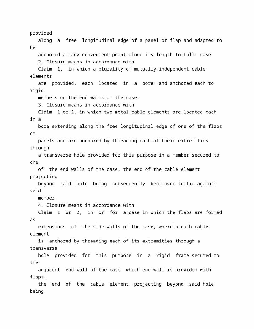
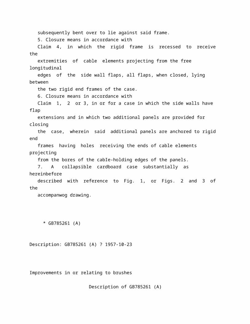
closed above and below by panels or flaps, closure means adapted to secure said panels or flaps in closed position comprising at least one thin flexible cable element passing through at least one bore provided along a free longitudinal edge of a panel or flap and adapted to be anchored at any convenient point along its length to tulle case 2. Closure means in accordance with Claim 1, in which a plurality of mutually independent cable elements are provided, each located in a bore and anchored each to rigid members on the end walls of the case. 3. Closure means in accordance with Claim 1 or 2, in which two metal cable elements are located each in a bore extending along the free longitudinal edge of one of the flaps or panels and are anchored by threading each of their extremities through a transverse hole provided for this purpose in a member secured to one of the end walls of the case, the end of the cable element projecting beyond said hole being subsequently bent over to lie against said member. 4. Closure means in accordance with Claim 1 or 2, in or for a case in which the flaps are formed as extensions of the side walls of the case, wherein each cable element is anchored by threading each of its extremities through a transverse hole provided for this purpose in a rigid frame secured to the adjacent end wall of the case, which end wall is provided with flaps, the end of the cable element projecting beyond said hole being subsequently bent over to lie against said frame. 5. Closure means in accordance with Claim 4, in which the rigid frame is recessed to receive the extremities of cable elements projecting from the free longitudinal edges of the side wall flaps, all flaps, when closed, lying between the two rigid end frames of the case. 6. Closure means in accordance with Claim 1, 2 or 3, in or for a case in which the side walls have flap extensions and in which two additional panels are provided for closing the case, wherein said additional panels are anchored to rigid end frames having holes receiving the ends of cable elements projecting from the bores of the cabIe-holding edges of the panels. 7. A collapsible cardboard case substantially as hereinbefore described with reference to Fig. 1, or Figs. 2 and 3 of the accompanwog drawing.
* GB785261 (A)

Description: GB785261 (A) ? 1957-10-23
Improvements in or relating to brushes
Description of GB785261 (A)
We, FREDERICK WICH & Co LIMITED, a British Company, of 29 Beak Street, London, W.1, and ERIC SEGER, a British Subject, of the Company's address, do hereby declare the invention, for which we pray that a patent may be granted to us, and the method by which it is to be performed, to be particularly described in and by the following statement: - This invention is for improvements in or relating to brushes and is concerned with shoe brushes, clothes brushes, hair brushes and the like of the type in which there is incorporated in, or combined with, the back of the brush a container for the reception of various articles, usually articles intended to be used in conjunction with the brush, which container is opened and closed by a sliding clasp fastener which runs around parts of the sides and ends of the brush, or by press button or other closures. The present invention has for one of its objects to protect the bristles of the brush from contact with other articles if say, for example, the brush is intended to be packed in a travelling case. According to the invention there is provided a brush of the aforesaid type, in which there is hinged to each of two opposite sides of the back of the brush a protective flap, the edges of which two flaps carry press studs or the like by which they can be secured together in such a position that the flaps overlie the bristles of the brush Preferably the dimensions of the flaps between their individual hinges and free edges are such that, when desired, the flaps can be folded around the back of the brush away from the bristles and their free edges secured together by the aforesaid press studs or the like In this way the flaps will be prevented from interfering with the full use of the bristles of the lPrice 3 s 6 d l brush when the latter is brought into operation. In one construction according to the invention the aforesaid container is located on the outside of the back of the brush and comprises two opposed sheets each of substantially the same contour as the back of the brush and each having a shallow flexible edging wall around its
perimeter, which edging walls are directed towards each other and are adapted to be connected by a sliding clasp fastener In such a construction. the protective flaps are preferably secured in place on the brush by having their hinging edges received by one of the said sheets of the container which is stuck to the back of the brush by an adhesive. For a more complete understanding of the invention, there will now be described, by way of example only and with reference to the accompanying drawings, one construction of combined shoe cleaning brush and container according to the invention It is to be understood, however, that the invention is not restricted to the precise constructional details set forth. In these drawings:Figure 1 is a perspective view taken from one side of the article, with the container open; Figure 2 is another perspective view, taken from the other side of the article; and Figure 3 is a cross section through the article with the container closed. Like reference numerals indicate like parts throughout the drawings. The shoe cleaning brush shown in the drawings has a back 10, bristles 11 and a container built on to the back 10 The back of the brush has an elongated contour with rounded ends and a slight reduction in width to constitute a waist for the brush. 785,261 PATENT SPECIFICATION Date of filing Complete Specification: Aug 7, 1956. Application Date: Dec 21, 1955 No 36708155. Complete Specification Published: Oct 23, 1957. Index at Acceptance -Class 19, A( 5: 9). International Classification:-A 46 b. COMPLETE SPECIFICATION. Improvements in or relating to Brushes. s O 785,261 Hinged to sides of the back 10 are two protective flaps 12 and 13 Each flap may, as shown, have its hinging edge shorter than its free edge, the latter corresponding with i the length of the bristled part of the brush and the hinging edge set back from both ends of the brush when it is mounted in place. One flap has near each end the male part 14 of a press stud fastener and the other flap il at similar places has the female part 15 of the fastener. The container which is built on to the back 10 comprises two opposed composite sheets each of substantially the same contour as the back 10 On composite sheet comprises laminae 16 and 17, and the other composite sheet comprises laminae 18 and 19 The laminae in each composite sheet are stitched together, but before this is done 2 U) there are inserted between the laminae 16 and 17 the hinging edges of the flaps 12 and 13, the margin of a shallow flexible edging wall
which extends around the perimeter ofthe laminae 16 and 17, and one margin of each of two hinging strips 21 and 22 which are situated one on each face of the wall 20, Similarly, before the laminae 18 and 19 are stitched together, there are inserted between them the margin of a shallow edging :ee wall 23 and one margin of each of the strips 21 and 22 The lamina 16 is secured to the back 10 of the brush by an adhesive The edging walls 20 and 23 are directed towards each other and are adapted to be connected 3)a by a sliding clasp fastener 24 which commences at one end of the strips 21 and 23 and runs right round to the other end A raised heel 25 is secured to one end of the exposed face of the lamina 18 and stitching 4 i) is visible at 26, these decorative effects being appropriate to a shoe cleaning brush, but if desired the heel 25 may be omitted. Shoe cleaning or like materials may be housed inside the container. 4 '.5 The flaps 12 and 13 may be made of any suitable material but conveniently flexible transparent synthetic "plastic" material may be used because this is light and can be easily cleaned The dimensions of the flaps t) between their individual hinges and free edges are such that it is easy either to fasten the stud parts 14 and 15 together with the flaps overlying the bristles 11 as shown in full lines in Figure 3, or to fasten them together turned back as shown in chain lines in Figure 3 thus exposing the brush for use. It is to be understood that the invention is not restricted to the precise constructional details set forth.
* Sitemap * Accessibility * Legal notice * Terms of use * Last updated: 08.04.2015 * Worldwide Database * 5.8.23.4; 93p
* GB785262 (A)
Description: GB785262 (A) ? 1957-10-23
Improvements in or relating to hypotensive and sedative preparations
Description of GB785262 (A)

COMPLETE SPECIFICATION Improvements in or relating to Hypotensive and Sedative Preparations We, SMITH KLINE & FRENCH INTER- NATIONAL C0.j a Corporation organized under the Laws of the State of Delaware, one of the United States of America, of 1530, Spring Garden Street, City of Philadelphia, State of Pennsylvania, United States of America, do hereby declare the invention, for which we pray that a patent may be granted to us, and the method by which it is to be performed, to be particularly described in and by the following statement: This invention relates to a hypotensive and sedative preparation and, more particularly, relates to a Rauwolfia alkaloid preparation in dosage unit from providing hypotensive and sedative action over a prolonged period of time of, for example, 6 to 24 hours. The preparation of this invention is useful in treating hypertension. It produces a surprisingly great reduction of blood pressure, for example, in benign hypertension. It is highly advantageous since it substantially reduces the side effects normally encountered with the drugs employed such as, for example, increased gastro-intestinal motility, nasal stuffiness and weakness. Further, the preparation in accordance with this invention achieves superior results using smaller dosage amounts of the potent drugs employed. The preparation of this invention is also useful due to its sedative action. This action is useful when the preparation is being used for the control of hypertension in that it reduces anxiety and tension which are inherent in the hypertension syndrome. It is also useful, for example, with menopausal patients where the combination of sedation and lowering of blood pressure has been found to be highly advantageous. It has an excellent sedative action on psychotic patients. The preparation of this invention is further advantageous in that provides sustained hypotensive and sedative action while the patient is asleep during the night. It also reduces the necessity for taking numerous doses during the daytime hours. The preparation in accordance with this invention contains a Rauwolfia alkaloid which may be in the form of a purified alkaloid or simply in the form of a species of Rauwolfia. Of the species of Rauwolfia, it is preferred to use Rauwolfia serpentina due to the highly advantageous results achieved. The crude root is preferably in a finely divided form. The crude root is readily

available commercially. Other species of Rauwolfia can be substituted for Rauwolfia serpentina. Exemplary are Rauwolfia heterophylla (Roem & Schult), Rauwolfia vomitoria (Mzelius), Rauwolfia selowii (Muell, Argos) and Rauwolfia canescens (Linn). Of the purified Rauwolfia alkaloids, reserpine is preferred. Seredine, 11-dimethoxy- reserpine, rescinnamine or deserpidine are further exemplary of purified Rauwolfia alkaloids. Materials obtained by extracting the Rauwolfia crude root with a suitable solvent or solvents such as ethyl alcohol and chloroform by any of the well known procedures used in the isolation of active materials from natural products are satisfactory. Such extracts normally have a potency much greater than the potency of the crude root weight for weight. Thus, a commercially available form of extract of Rauwolfia serpentina marketed as "Rauwiloid" (Registered Trade Mark) (alseroxylon) by Riker Laboratories has about 50 times the potency of the crude root weight for weight Since the potency of the various Rauwolfia alkaloids varies widely, it is necessary to specify a "standard" in order to give dosage ranges. An acceptable standard is the alkaloid reserpine and the dosage ranges for the Rauwolfia alkaloid will, herein and in the claims, be referred to reserpine as the standard. The dosage unit in accordance with this invention has an initial dose of the Rauwolfia alkaloid which is released immediately on ingestion to provide a predetermined therapeutic level of the Rauwolfia alkaloid and a sustained release dose of Rauwolfia alkaloid which is gradually released over an extended period of time through the use of a large number of small timed delay coated pellets variously coated with material resistant to disintegration or dispersion in the gastro-intestinal tract to maintain the therapeutic level substantially constant over an extended period of time. More specifically, the dosage unit in accordance with this invention comprises an initial dose of Rauwolfia alkaloid in an amount equivalent to from about 0.03 mgm. to about 2 mgm. of reserpine and which is ready for immediate release to the body. In addition, the dosage unit contains a sustained release dose of Rauwolfia alkaloid in an amount in the range of from 100% to about 500% by weight of the initial dose of the Rauwolfia alkaloid in not less than about 50 and preferably from about 300 to about 1000 timed-delay coated pellets, each pellet preferably containing about the same amount of Rauwolfia alkaloid. It will be obvious that the upper limit to the number of pellets is merely one of convenience. Preparations having in excess of 1000 coated pellets have been found to be conveniently made and satisfactory.

Where the preparation is to be employed for the treatment of hypertensive patients or to provide a mild sedative action, it is preferred to have an initial dose of Rauwolfia alkaloid in an amount equivalent to from about 0.05 mgm. to about 0.3 mgm of reserpine and which is ready for immediate release and a sustained release dose of Rauwolfia alkaloid which is from about 100% to about 500% of the initial dose. Advantageously in treating hypertensive patients and for providing a mild sedative action, an initial dose of Rauwolfia alkaloid in an amount equivalent to from about .05 mgm. to about .18 mgm of reserpine and which is ready for immediate release and a sustained release dose of from about 100% to about 400% of the initial dose is employed. Where the preparation is to be used in the treatment of psychotics, it is preferred to have the initial dose of Rauwolfia alkaloid which is ready for immediate release in the range of an amount equivalent to from about 0.5 mgm. to about 2 mgm. of reserpine and the sustained release dose of Rauwolfia alkaloid in an amount of from about 100% to about 500% of the initial dose. Advantageously in treating psychotics, an initial dose of Rauwolfia alkaloid in an amount equivalent to from about 1 mgm. to about 1.5 mgm. of reserpine and a sustained release dose of from about 100% to about 400% of the initial dose is employed. The desired product can be achieved, for example, by combining the uncoated selected pellets of Rauwolfia alkaloid with one or more different groups of coated pellets. It is preferred to use two to three groups as a practical matter, but from one to eight groups are satisfactory. It has been found that if the required thickness of coating for release at the end of nine hours is X and the number of coated groups is Y, the first coated group may have X a median coating of -, the next group a Y 2X 3X median coating of - , the next , and so Y Y on, depending on the number of groups. Following this formula, it has been found that if either of the following techniques are used to make a predetermined median coatings for any one group, the coatings will vary within the range of from about 30% to about 40%, on either side of the median coating. A satisfactory approximation is achieved where the median coating weights are made up using the above formulae with X representing the weight of the median coating of the group which is released last. Pellets of the selected Rauwolfia alkaloid can be readily prepared by placing small, substantially spherical sugar pellets of from about 12 to 30 mesh size in a rotating pan and coating them with a powder of

the selected Rauwolfia alkaloid. Eefore the addition of the powder the sugar pellets are wetted in the conventional manner using, for example, syrup U.S.P., or a gelatin coating solution such as one having the following formula: Parts by Weight Sucrose - - 100 Gelatin - - 8 Acacia - - 6 Water - - 70 If desired, the powdered Rauwolfia alkaloid can be extended with, for example, powdered calcium sulfate dihydrate, powdered starch or powdered acacia prior to being used in the process. The coating operation is repeated until each pellet contains the desired amount of selected Rauwolfia alkaloid. Pellets of the selected Rauwolfia alkaloid can also be similarly prepared using beads formed from a synthetic resin such as, for example, a sulfonic or carboxylic ion exchange resin, such as a copolymer of methacrylic acid and dibenzene, nitrocellulose spheres or rape seeds. The method of forming pellets containing a Rauwolfia alkaloid can be modified from the above described method by dissolving the Rauwolfia alkaloid in an adhesive coating solution and applying the adhesive coating solution containing the Rauwolfia alkaloid to the seeds. Alternatively, instead of forming a seed and then coating it with medicament, the seed can be formed using the medicament as the basic component of the seed. This is accomplished by utilizing fine particles of inert material of a diameter of from about 420 to 250 microns, such as extra fine granulated sugar or farina (cereal meal). The Rauwolfia alkaloid is adhered to the fine particles by an adhesive solution in the same manner as the Rauwolfia alkaloid is adhered to the sugar pellets as described above. After the Rauwolfia alkaloid pellets have been formed, a number of them are provided with a time delay coating which is capable of being slowly disintegrated or dispersed in the gastro-intestinal tract. By way of example, such a coating may be a fat or a mixture of a fat and a wax. The most common method of applying the time delay coating is to place the desired coating material in solution and spray it over the pellets while rotating the pellets in the coating pan. The time delay coating may be, for example, any ingestible coating resistant to disintegration in the gastrointestinal tract, such as for example, glyceryl-distearate. By way of further example, it may be a

mixture of glycerylmonostearate and beeswax, the glyceryl monostearate being within the range of from 50 to 95% by weight of the total coating. It is preferred to have the glycerylmonostearate about 70% by weight of the total coating. Any other water-nnsoluble ingestible wax can be substituted for beeswax. Thus, for example, Japan wax, paraffin, carnauba wax, bayberry wax, and other animal, insect, plant or other waterinsoluble, non-toxic, wax-like substance such as, for example, spermaceti are satisfactory. Any other slowly digestible, emulsifiable or dispersible liquid-like compounds, such as higher fatty acids having 12 to 22 carbon atoms, fatty alcohols as well as higher esters and sterol derivatives may be used in place of glycerylmonostrearate alone or in combination with wax. Thus, for example, glyceryl tristearate, cetyl palmitate, diglycol ste ar ate, glyceryl myristate, triethylene glycol monostearate, cetyl alcohol, cholesterol, and stearyl alcohol, are satisfactory, alone or admixed with wax. It is preferred to use alcohols having from 12 to 22 carbon atoms or esters formed from fatty acids having from 12 to 22 carbon atoms and said alcohols. Ethyl alcohol or carbon tetrachloride heated to about 60 C. is a satisfactory solvent for the above mentioned fat and wax-fat coatings and forms a suitable spray when the solids are within the range of from 5 to 25 % of the solution. When prepared the uncoated Rauwolfia alkaloid together with the time delay coated Rauwolfia alkaloid pellets can be suitably put up as, for example, in a hard or soft gelatin capsule or in any other form convient for the administration of a unit dose. This invention will be further clarified by reading the following description in conjunction with the drawings in which : - Figure 1 is a plan view of a capsule conraining pellets in accordance with this invention. Figure 2 is a sectional view of typical pellets contained in the capsule of Figure 1. As shown in Figure 1 a two-piece gelatin capsule 2 contains pellets 3 of a selected Rauwolfia alkaloid, the pellets being uncoated. Capsule 2 further contains timedelay coated Rauwolfia alkaloid pellets 4, 6 and 8. As will be apparent from a study of Figure 1, these various pellets are in random distribution, there being approximately an equal number of each group or type of pellet. It will be appreciated that an aqual number of each type of pellet is not necessary, considerable variation being consonant with maintaining a substantially constant therapeutic level. As shown in Figure 2, each of the pellets 4, 6 and 8 has a center or

core 10 of the selected Rauwolfia alkaloid. The pellets 4 have a time delay coating 12 which is of greater thickness than the time delay coating 14 of pellets 6 which, in turn, is of greater thickness than the time delay coating 16 of pellets 8. Coatings 12, 14 and 16, shown in Figure 2, represent the median coatings of the groups formed by pellets 4, 6 and 8, it being appreciated that, as previously described, the coatings of each group of pellets will vary in order to provide gradual release of the selected Rauwolfia alkaloid over a ten to twelve hour period. The following examples will further clarify the invention : - EXAMPLE 1 MATERIAL LIST 1. Sugar Pellets-22000 gm. (Pass through a No. 20 and collect on a No. 30 US Standard Mesh Sieve) 2. Adhesive Solution (Polyvinyl Pyrrolidone Solution)-2000 cc. Polyvinyl pyrrolidone - 2.0% w/v Ethyl alcohol (USP) - 40.0% v/v Water (USP) - - - 5.0% v/v Trichioroethylene q.s. - 100.0% v/v The alcohol and water are mixed and the polyvinyl pyrrolidone slowly added. The batch is mixed until solution is complete and then the trichlorethylene is added. 3. Medicated Adhesive Solution120 cc. Reserpine - - - - 76.8 gm. Adhesive solution (PVP solution) q.s. - - - 1200 cc. 1000 cc. of adhesive solution is added to Reserpine and stirred until the alkaloid is dissolved; then the solution is brought up to volume. 4. Gelatin Solution (4%)1000 cc. Gelatin (USP) 4% w/v Water (USP) 401% - q.s. 100% Ethyl alcohol q.s. 100% v/v (USP) - - 60% 5. Starch-Sugar Coating Powder4000 gm. Starch (USP) - - - 50% w/w Sugar (powdered) - - 50% w/w Mixed well and passed through US No. 25 sieve. 6. Wax-Fat Coating Solution No. 1-20 Liters <img class="EMIRef" id="026700763-00040001" /> Glyceryl monostearate 90% t 5 kg. White wax (USP) - 10) ( 5 kg. White wax (USP) - 10%
Ethyl alcohol (USP) 15 liters 7. Wax-Fat Coating Solution No. 2-6 Liters Glyceryl distearate - - - 1.5 kg. Ethyl alcohol (USP) - - 4.5 liters 8. Purified Talc, USP 9. Capsules Size 3 hard gelatin capsule. WORKING DIRECTIONS A. MANUFACTURE OF MEDICATED CENTERS The sugar pellets are placed in a suitable coating pan and set in motion. Enough medicated adhesive solution is applied slowly to wet the pellets evenly. Enough starchsugar coating powder is then sprinkled on to almost dry the pellets. This batch is mixed well and rolled until no odor of solvent remains. This operation is repeated until all the medicated adhesive solution has been applied. Three finishing coats of gelatin solution (4%) and starch-sugar coating powder are then applied, and the batch carefully dried. Lumps and fines are screened out. B. MANUFACTURE OF WAX-FAT COATED PELLETS-12% COAT t of the amount of medicated pellets obtained in "A" is placed in a suitable coating pan which is set in motion. The waxfat coating solution No. 1 is sprayed on until the material has a 10% coat (by weight). Then enough wax-fat coating solution No. 2 is applied until an additional 2% coat (by weight) is present These operations are accomplished by using a suitable spraying unit and applying warm (60 C.) wax-fat coating solution until the pellets are evenly wetted and slide as a mass. Then spraying is discontinued and the pellets are air-dried in the rotating pan until all odor of solvent disappears from the pan. The pellets are placed in suitable trays and dried overnight Lumps and fines are screened out. The pellets are liberally dusted with talc. C. MANUFACTURE OF WAX-FAT COATED PELLETS18% COAT 9 of the amount of medicated pellets obtained in "A" is placed in a suitable coating pan and set in motion. The procedure described in "B" above is followed except a 16% coat (by weight) of wax-fat coating solution No. 1, and a 2% coat (by weight) of waxfat coating solution No. 2 is applied. The batch is air dried carefully until all odor of solvent has disappeared from the pan. Lumps and fines are screened out and the pellets given a liberal dusting of talc. D. PREPARATION OF BULK MIX FOR ENCAPSULATION Equal numbers of uncoated medicated pellets made as in "A" above, 12% coated pellets made as in "B" above and 18% coated pellets made as in "C" above are mixed. A size 3 hard gelatin capsule is filled with a

sufficient amount of the mixture to provide a 0.5 mgm. total does of Reserpine, a useful preparation for treating hypertensive patients and for providing mild sedation. EXAMPLE 2 MATERIAL LIST 1. Sugar Pellets--34300gm, Passed through a No. 25 and collected on a No. 30 US Standard Mesh Sieve) 2. Adhesive Solution (Alcoholic Gelatin Solution)-2000 cc. Gelatin (USP) - - - 2000 gm. Water (USP) - - - 6000 gm. Hydrochloric acid (USP) - 120 gm. Ethyl alcohol (USP) - - 12000 gm. The acid is combined with approximately 500 cc. of water. The remainder of the water is placed in a steamjacketed kettle and the gelatin is added with constant stirring and heat to effect solution. The batch is cooled to 60 C. and, while mixing, the diluted acid and the alcohol are added. The batch is heated to about 70" C., the container covered and held at this temperature for 2 hour. The batch is cooled to room temperature and sufficient 70% alcohol* is added to measure 22.5 liters at room temperature (20 kg. by weight). *70% Alcohol Water, (USP) - - 30% v/v Alcohol (USP) qs. ad. 100% v/v 3. Medicated Coating Powder Alseroxylon fraction - - 50% Starch (USP) - - - 25% Sucrose (USP) (powdered) 25% The ingredients are mixed well and reduced to a very fine powder (US No. 120 Standard Mesh Sieve Size). 4. Finishing Powder-9000 gm. Colloidal Kaolin (NF) - - 50% Starch (USP) - - - 50% Mixed well. 5. Finishing Solution-9000 cc. Gelatin (USP) - - 450 gm. Sucrose (USP) - - 3600 gm. Water (USP) - - 4050 gm. Ethyl alcohol (USP) - 4800 cc. (Makes about 12 liters). The water is placed in a suitable container and a mixture of the gelatin and sugar slowly added. This suspension is warmed on a steam bath to about 85" C. with occasionally mixing until all the gelatin
and sugar have melted, it is then removed from steam bath. The alcohol is added slowly with thorough mixing. 6. Wax-Fat Coating Solution No. 1-20 Liters Glyceryl monostearate (NF) - - - 90% White wax (USP) - 10% 5 kg. Ethyl alcohol (USP) - 15 kg. 7. Wax-Fat Coating Solution No. 2-6 Liters Glyceryl distearate - 1.5 kg. Ethyl alcohol (USP) - 4.5 liters 8. Purified Talc (USP)-1000 gm. 9. Capsules Size 3 hard gelatin capsules. WORKING DIRECTIONS A. MANUFACTURE OF MEDICATED CENTERS The sugar pellets are placed in a suitable coating pan and set in motion. Enough adhesive solution is applied to wet the pellets evenly. Then enough medicated coating powder is sprinkled on until the pellets are evenly coated and no excess of powder is present in the coating pan. This operation is repeated until all the medicated coating powder has been applied. The pellets are mixed well and dried. These pellets are then evenly wetted with finishing solution, evenly coated with finishing powder with on excess powder present and dried repeatedly until all of the finishing powder has been applied. The batch is dried carefully and lumps and fines screened out B. MANUFACTURE OF WAX-FAT COATED PELLETS12% COAT 2 of the amount of medicated pellets, obtained in "A", are placed in a suitable coating pan and set in motion. The wax-fat coating solution No. 1 is sprayed on until the material has a 10% coat (by weight). Then enough wax-fat coating solution No. 2 is applied until an additional 2% coat (by weight) is present. These operations are accomplished by using a suitable spraying unit and applying warm (60 C.) wax-fat coating solution until the pellets are evenly wetted and slide as a mass. Then spraying is discontinued and the pellets air dried until all odor of solvent disappears from the pan. The pellets are placed in suitable trays and dried overnight. Lumps and fines are screened out and the pellets dusted liberally with talc. C. MANUFACTURE OF WAX-FAT COATED PELLETS18% COAT , of the amount of medicated pellets, obtained in " A ", are placed in a suitable coating pan and set in motion. The procedure described in
"B" above is followed except a 16% coat (by weight) of wax-fat coating solution No. 1, and a 2% coat (by weight) of waxfat coating solution No. 2 is applied. The batch is air dried carefully, until all odor of solvent disappears from the pan. Lumps and fines are screened out and the pellets given a liberal dusting of talc. D. PREPARATION OF BULK MIX FOR ENCAPSULATION Equal numbers of uncoated medicated pellets made as in "A" above, 12% coated pellets made as in "B" above, and 18% ;oated pellets made as in "C" above are mixed. A size 3 hard gelatin capsule is filled with a sufficient amount of the mixture to provide a 6 mg. total dose of alseroxylon fraction. EXAMPLE 3 The proceduret of Example 1 is repeated with the exception that the medicated adhesive solution contains reserpine in an amount of 230.4 gm. EXAMPLE 4 The procedure of Example 2 is repeated with the exception that the alseroxylon fraction is present in the medicated coating powder in an amount of 90%. What we claim is: 1. A therapeutic preparation in dosage unit form comprising: an ingestible capsule containing an initial dosage of a Rauwolfia alkaloid in an amount equivalent to from about 0.03 mgm. to about 2 mgm. of reserpine to provide a predetermined therapeutic level of the Rauwolfia alkaloid, a minimum of about 50 pellets containing a Rauwolfia alkaloid in an amount of from about 100% to about 500% by weight of the said initial dosage and having ingestible coatings resistant to disintegration in the gastro-intestinal tract the coatings providing for the gradual release of the Rauwolfia alkaloid in said tract, said preparation maintaining a substantially constant therapeutic level of the Rauwolfia alkaloid. 2. A therapeutic preparation in accordance with Claim 1 in which the initial dose of Rauwolfia alkaloid is in an amount equivalent to from 0.05 mgm. to 0.3 mgm. or reserpine. 3. A therapeutic preparation in accordance with Claim 1 in which the initial dose of Rauwolfia alkaloid is in an amount equivalent to from 0.05 mgm. to 0.18 mgm. of reserpine and the pellets contain a Rauwolfia alkaloid in an amount of from about 100% to about 400% by weight of the initial dosage.
4. A therapeutic preparation in accordance with Claim 1 in which the initial dose of Rauwolfia alkaloid is in an amount equivalent to from 0.5 mgm. to 2 mgm. of reserpine. 5. A therapeutic preparation in accordance with Claim 1 in which the initial dose of Rauwolfia alkaloid is in an amount equivalent to from 1 mgm. to 1.5 mgm. of reserpine and the pellets contain a Rauwolfia alkaloid in an amount of from about 100% to about 400% by weight of the initial dosage. 6. A therapeutic preparation in accordance with any of the preceding claims in which the ingestible coatings are of varying thickness. 7. A therapeutic preparation substantially as hereinbefore described, with reference to any of the specific exarmples, and to the accompanying drawings