4973 series conductivity cells installation and ... · 6/99 4973 series conductivity cells –...
TRANSCRIPT
4973 Series Conductivity CellsInstallation and Maintenance Manual
70-82-25-17
Rev 16/99
ii 4973 Series Conductivity Cells – Installation and Maintenance Manual 6/99
Copyright, Notices, and Trademarks
Printed in U.S.A. – © Copyright 1999 by Honeywell Inc.
Revision 1 – 6/99
While this information is presented in good faith and believed to beaccurate, Honeywell disclaims the implied warranties ofmerchantability and fitness for a particular purpose and makes noexpress warranties except as may be stated in its written agreementwith and for its customer.
In no event is Honeywell liable to anyone for any indirect, special orconsequential damages. The information and specifications in thisdocument are subject to change without notice.
HoneywellIndustrial Automation and Control
Automation College2820 West Kelton Lane
Phoenix, AZ 85023
(602) 313-5669
6/99 4973 Series Conductivity Cells – Installation and Maintenance Manual iii
About This Document
AbstractThe purpose of this manual is to support the installation and maintenance of the 4973 Series ConductivityCells.
Revision NotesThe following list provides notes concerning all revisions of this document.
Rev. ID Date Notes
0 10/96 This document is the initial release of the Honeywell version of the 4973Series Conductivity Cell Installation and Maintenance Manual. Thispublication was originally released under the L&N system as 277067 Rev.N1.
1 6/99 Edits were made to add information for the 9782C and to correct someerroneous information.
References
Honeywell Documents
The following list identifies all Honeywell documents that may be sources of reference for the materialdiscussed in this publication.
Document Title ID #
9782 Series Two Cell Conductivity/ResistivityAnalyzer/Controller Operator’s Manual
70-82-25-74
7079-17 Two-Wire Transmitter for Conductivity/ResistivityOperation and Maintenance Manual
70-82-25-51
ContactsThe following list identifies important contacts within Honeywell.
Organization Telephone Address
Honeywell TAC 1-800-423-9883 1100 Virginia Drive
Fort Washington, PA 199034
iv 4973 Series Conductivity Cells – Installation and Maintenance Manual 6/99
Contents
1. INTRODUCTION....................................................................................................11.1 Overview.........................................................................................................................................1
1.2 Description......................................................................................................................................10.01 and 0.1 Cell Constants ...............................................................................................................11 and 10 Cell Constants .....................................................................................................................1
2. SPECIFICATIONS .................................................................................................52.1 4973 Series Cell ..............................................................................................................................5
2.2 Flow Chamber 055919....................................................................................................................5
3. INSTALLATION .....................................................................................................73.1 General Requirements.....................................................................................................................7
3.2 Insertion-Type Mounting ................................................................................................................7Installation .........................................................................................................................................7
3.3 Flow-Type Mounting ......................................................................................................................8Installation .........................................................................................................................................8
3.4 Torque Recommendations ..............................................................................................................8
4. ELECTRICAL CONNECTIONS .............................................................................94.1 Overview.........................................................................................................................................9
5. MAINTENANCE ...................................................................................................115.1 Overview.......................................................................................................................................11
5.2 To Clean The Cell.........................................................................................................................11
5.3 Check Conductivity System..........................................................................................................11
5.4 Troubleshooting............................................................................................................................11
5.5 Air Entrapped in Cell Flow Channel ............................................................................................12
5.6 Accessories and Parts ...................................................................................................................12
5.7 Ordering Information ....................................................................................................................13
6/99 4973 Series Conductivity Cells – Installation and Maintenance Manual v
Figures
Figure 1-1 4973 Series Conductivity Cells, For flow- and insertion-type applications._______________ 2Figure 1-2 Recommended Locations for Mounting a Conductivity Cell __________________________ 3Figure 1-3 Two Piping Arrangements for the Cell ___________________________________________ 3Figure 5-1 Dimension Drawing for 055919 Flow Chamber __________________________________ 15Figure 5-2 Outline and Dimensions for 4973-❏-❏-X1-00-❏ Conductivity Cell with Universal Head__ 16Figure 5-3 Outline and Dimensions for 4973-❏-❏-X7/20-00-❏ Conductivity Cell_________________ 17Figure 5-4 Installation Diagram, 4973 Cells, Table II=333, with junction box head connected to 7082
Analyzer _______________________________________________________________________ 18Figure 5-5 Installation Diagram, 4973 Cells, Table II=333, with junction box head connected to 9782
Analyzer _______________________________________________________________________ 19Figure 5-6 Installation Diagram, 4973 Cells, with 7’ or 20’ leads directly connected to 7082 Analyzer
or connected to junction box_______________________________________________________ 20Figure 5-7 Installation Diagram, 4973 Cells, with 7’ or 20’ leads directly connected to 9782 Analyzer
or connected to junction box_______________________________________________________ 21

vi 4973 Series Conductivity Cells – Installation and Maintenance Manual 6/99
Introduction
6/99 4973 Series Conductivity Cells – Installation and Maintenance Manual 1
1. Introduction
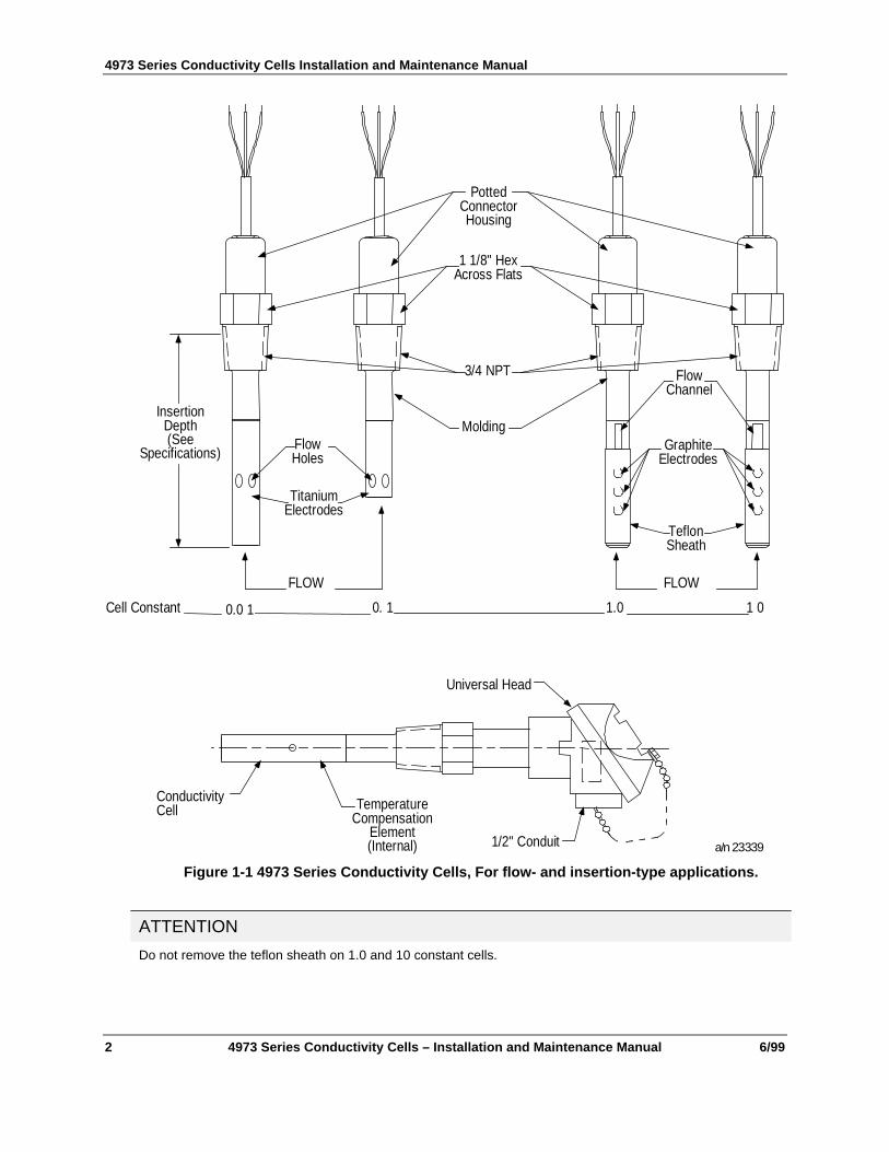
1.1 OverviewThe 4973 Series cells, Figure 1-1, have a rugged configuration for reliable, continuous measurements ofelectrolytic conductivity in industrial water processes at temperatures up to 140°C at 250 psig. They areapplicable to such measurements as the effluent of distillation equipment; anion, cationic and mixed bed ionexchangers; monitoring and controlling of washing electronic components; plating rinse tank control; boilerwater condensate; boiler hot well measurements and cooling tower blowdown, and many others.
Made of polyethersulfone (PES) construction for high-corrosion resistance, the cells are supplied with 0.01and 0.1 cell constants having titanium electrodes, and 1.0 and 10.0 cell constants with high-density, graphiteelectrodes.
The 4973 Cells are equipped with an integral standard 7 foot lead or optional 20 foot lead, and may beequipped with a junction box type (universal) head with terminal connections for longer lead lengths.
For insertion applications, the 3/4” NPT male thread permits permanent installation in a pipe or tank; thecell may also be used as a laboratory dip-type cell for batch sampling.
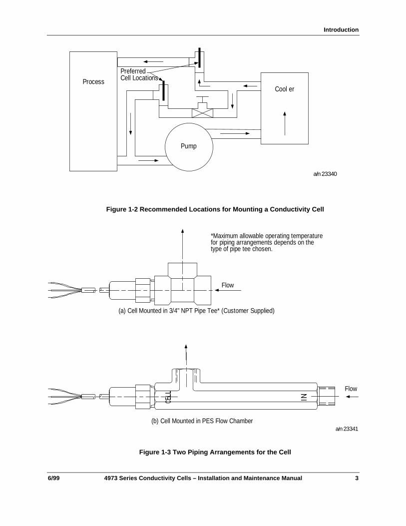
For flow applications, the cell can be installed directly into a process stream as shown in Figure 1-2 byusing the 055919 Flow Chamber or a 3/4” pipe tee as shown in Figure 1-3. These arrangements aredesigned to keep both the temperature compensator and cell in the main stream flow so that the cell willrespond more quickly and accurately to process changes of both solution concentration and temperature.
1.2 DescriptionAll conductivity cells in the 4973 Series are suitable for use in both flow - and insertion - type installations.They are one-piece molded units that cannot come apart and therefore have no replacement parts. Each hasa 3/4” NPT thread.
The physical appearance of the cells is shown in Figure 1-1. The 0.01, 0.1, 1 and 10 cell constants aresimilar in construction with differences as noted below.
0.01 and 0.1 Cell Constants
The 0.01 cell differs from the others only by its outer electrode length of 2-3/4”. The temperaturecompensation sensor is located inside the inner electrode. The holes in the outer electrode provide passagefor the solution being measured. The 0.1 cell is similar to the 0.01 type except that its outer electrodelength is 2”. The temperature compensation sensor is located inside the inner electrode.
1 and 10 Cell Constants
The 1 and 10 cell constant types are similar but differ in the width of flow channel (that serves to conductthe solution being measured past the electrodes of the cell) as well as size and spacing of the electrodes.The electrodes are graphite, 1/4” D for the 1 cell constant and 1/8” D for the 10 cell constant. Thetemperature compensating sensor is integral with the cell body.
4973 Series Conductivity Cells Installation and Maintenance Manual
2 4973 Series Conductivity Cells – Installation and Maintenance Manual 6/99
Universal Head
1/2" Conduit
TemperatureCompensation
Element(Internal)
ConductivityCell
PottedConnectorHousing
1 1/8" HexAcross Flats
3/4 NPT
MoldingFlowHoles
FlowChannel
GraphiteElectrodes
TeflonSheath
FLOW FLOW
TitaniumElectrodes
InsertionDepth(See
Specifications)
0.0 1 0. 1 1.0 1 0Cell Constant
a/n 23339
Figure 1-1 4973 Series Conductivity Cells, For flow- and insertion-type applications.
ATTENTION
Do not remove the teflon sheath on 1.0 and 10 constant cells.
Introduction
6/99 4973 Series Conductivity Cells – Installation and Maintenance Manual 3
PreferredCell Locations
Cool er
Pump
Process
a/n 23340
Figure 1-2 Recommended Locations for Mounting a Conductivity Cell
Flow
(b) Cell Mounted in PES Flow Chamber
Flow
(a) Cell Mounted in 3/4" NPT Pipe Tee* (Customer Supplied)
*Maximum allowable operating temperaturefor piping arrangements depends on thetype of pipe tee chosen.
a/n 23341
Figure 1-3 Two Piping Arrangements for the Cell

4973 Series Conductivity Cells Installation and Maintenance Manual
4 4973 Series Conductivity Cells – Installation and Maintenance Manual 6/99
Specifications
6/99 4973 Series Conductivity Cells – Installation and Maintenance Manual 5
2. Specifications
2.1 4973 Series CellAutomatic Temperature Compensation: Temperature sensor integral with all cells.
Cell Constants: 0.1, 0.1, 1.0, and 10 cm-1.
Wetted Parts:
Cell Body: PES (polyethersulfone).
Electrodes: 0.01 and 0.1 constant, titanium
1.0 and 10 constant, high density graphite with Teflon sheath.
Maximum Temperature: 140°C (284°F) at rated pressure.
Temperature limit for PVC wire is 105°C (221°F).
Maximum Pressure: 250 psig (1724 kPa) at rated temperature.
Electrical Connections: Standard 7 foot lead, 3 ro 4 conductor, nonshielded 18-gage PVC insulated wire.Optional 20 foot lead, 3 or 4 conductor, nonshielded 18-gage PVC insulated wire, see Figure 5-3. Optionalhead-type junction box (universal head) with terminals for extension wire and ½” inch NPT conduitconnection, see Figure 5-2.
Insertion: 3/4 inch NPT, male for Schedule 40 and 80 pipes.
Insertion Depth: 3-1/2” (89 mm) for 1, 10, and 0.01 cell constants from solution end of 3/4” NPT malethread; 2-1/2” (64mm) for 0.1cell constant.
2.2 Flow Chamber 055919Material: Polyethersulfone.
Maximum Flow: 5gpm @ 40 psig and atmospheric discharge.
Maximum Pressure: 200 psig @ 25°C.
Maximum Temperature: 140°C @ atmospheric pressure.
Dimensions: See Figure 5-1
4973 Series Conductivity Cells Installation and Maintenance Manual
6 4973 Series Conductivity Cells – Installation and Maintenance Manual 6/99
Installation
6/99 4973 Series Conductivity Cells – Installation and Maintenance Manual 7
3. Installation
3.1 General RequirementsObserve the following before installing a conductivity cell. Specific requirements for particular types ofinstallation are given in Sections 3.2 and 3.3.
• Do not remove the Teflon sheath on 1or 10 constant cells, as this will change the cell constant value.
• Do not use the cell in solutions which can affect the fittings or the cell materials. If in doubt, contactHoneywell.
• Avoid all chlorinated hydrocarbons.Titanium and PES (0.01 and 0.1 cell constants) and Graphite, Teflon and PES (1.0 and 10 cellconstants) are the only cell materials in contact with measured solutions. These materials are inert tocorrosive chemicals such as mineral acids, oxidizing agents and caustic solutions.
• Avoid trapped air; see that air is not trapped in the cell flow channels.
• Do not use the cell in solutions having temperatures or pressures greater than the maximum limitsstated in the Specifications.
• Avoid locations where the operator must take an awkward position to install or remove the cell.
• When tightening, do not exceed the torque limits provided in Section 3-4. Over-tightening can breakthe cell or severely stress it causing cracks to develop, leading to eventual malfunction.
3.2 Insertion-Type MountingIn addition to the General Requirements outlined above, note the following with regard to insertion-typemounting:
• Make certain the liquid head is above the cell location during measurement. A vertical insertion (fromabove) or a horizontal insertion can be used.
• Allow at least one-half inch clearance beyond the end of the cell and 1/8 to 3/16 inch radius clearanceto permit circulation of the solution.
• It is usually best to have the solution flow up into the end of the cell since it is less likely to result inclogging by solids settling in the cell channels.
• To be sure that a representative sample is being measured at all times, the solution must continuouslymove through the cell channels. In a rapidly moving solution, the assembly may be mounted so that theexisting circulation forces the solution through the channels. When measurements are made inquiescent solutions, artificial means must be provided to force the solution through the cell. In somecases, this may be accomplished by moving the cell up and down.
Installation
1. Tighten the cell into a 3/4” NPT threaded opening (do not exceed a tightening torque greater than thatindicated in Section 3.4) using a Teflon thread compound (preferably Teflon tape).
4973 Series Conductivity Cells Installation and Maintenance Manual
8 4973 Series Conductivity Cells – Installation and Maintenance Manual 6/99
3.3 Flow-Type MountingIn addition to the General Requirements outlined in Section 3.1, note the following with regard to flow-typemounting:
• When mounting the cell in a pipe tee or flow chamber such as shown in Figure 1-3, have the solutionenter the tee from below and exit to the side or from side and exit top. Be sure the electrodes arealways as far as possible below the horizontal pipe run so that they are always covered to insureflooding of the cell under all conditions; otherwise, the conductivity reading may indicate a value thatis lower than expected.
• In general, the cell should be mounted so that the sample will flow through the channel toward themounting end of the cell, exiting through the other channel hole or through the outer electrode holes.See Figure 1-1.
• Locate the cell on the pressure side, not the vacuum side, of pumps. See Figure 1-2.
• Avoid a horizontal cell mounting having the flow channel, see Figure 1-1, opposite to the flow exit ofthe pipe line, especially for the 1 and 10 constant cells. If necessary, refer to Section 5.5.
• The 3/4” tee arrangement, Figure 1-3, assures that the cell is immersed well into the flow stream toobtain a representative sample. The tee is not supplied.
Installation
1. Tighten the cell into a 3/4” pipe tee (do not exceed a tightening torque greater than that indicated inSection 3.4).
2. If the flow-cell housing is used, assemble the cell and housing and install it in the process flow line orin a bypass line as indicated in Figure 1-2.
3. To avoid cracking the 055919 flow chamber, use Teflon tape on cell threads and tighten cell onlyenough to prevent leakage.
3.4 Torque RecommendationsFor inserting a cell in metal fittings or bushings - 40 ft-lb maximum. For inserting a cell in plastic fittings orbushings - 10 ft-lb maximum. Always use pipe sealant (preferably Teflon tape).
Installation
6/99 4973 Series Conductivity Cells – Installation and Maintenance Manual 9
4. Electrical Connections
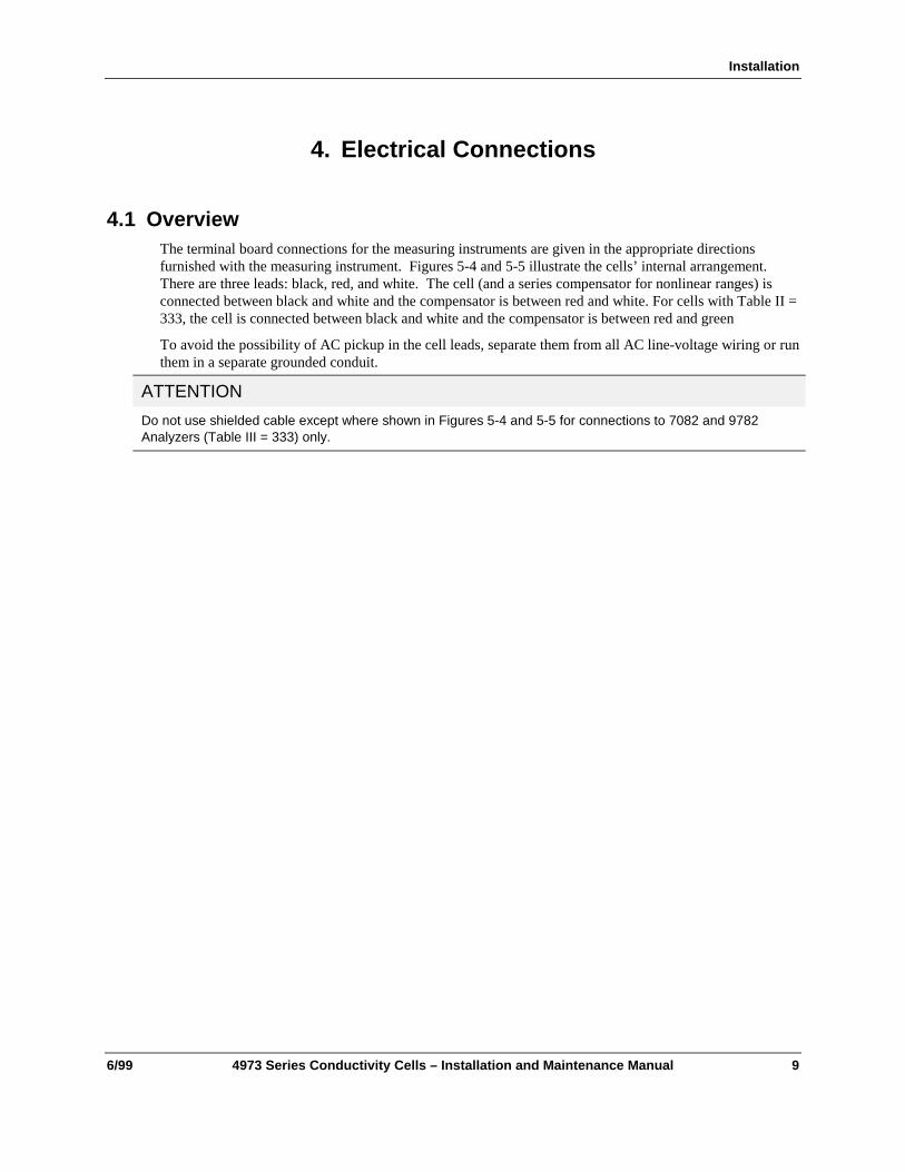
4.1 OverviewThe terminal board connections for the measuring instruments are given in the appropriate directionsfurnished with the measuring instrument. Figures 5-4 and 5-5 illustrate the cells’ internal arrangement.There are three leads: black, red, and white. The cell (and a series compensator for nonlinear ranges) isconnected between black and white and the compensator is between red and white. For cells with Table II =333, the cell is connected between black and white and the compensator is between red and green
To avoid the possibility of AC pickup in the cell leads, separate them from all AC line-voltage wiring or runthem in a separate grounded conduit.
ATTENTION
Do not use shielded cable except where shown in Figures 5-4 and 5-5 for connections to 7082 and 9782Analyzers (Table III = 333) only.

4973 Series Conductivity Cells Installation and Maintenance Manual
10 4973 Series Conductivity Cells – Installation and Maintenance Manual 6/99
Maintenance
6/99 4973 Series Conductivity Cells – Installation and Maintenance Manual 11
5. Maintenance
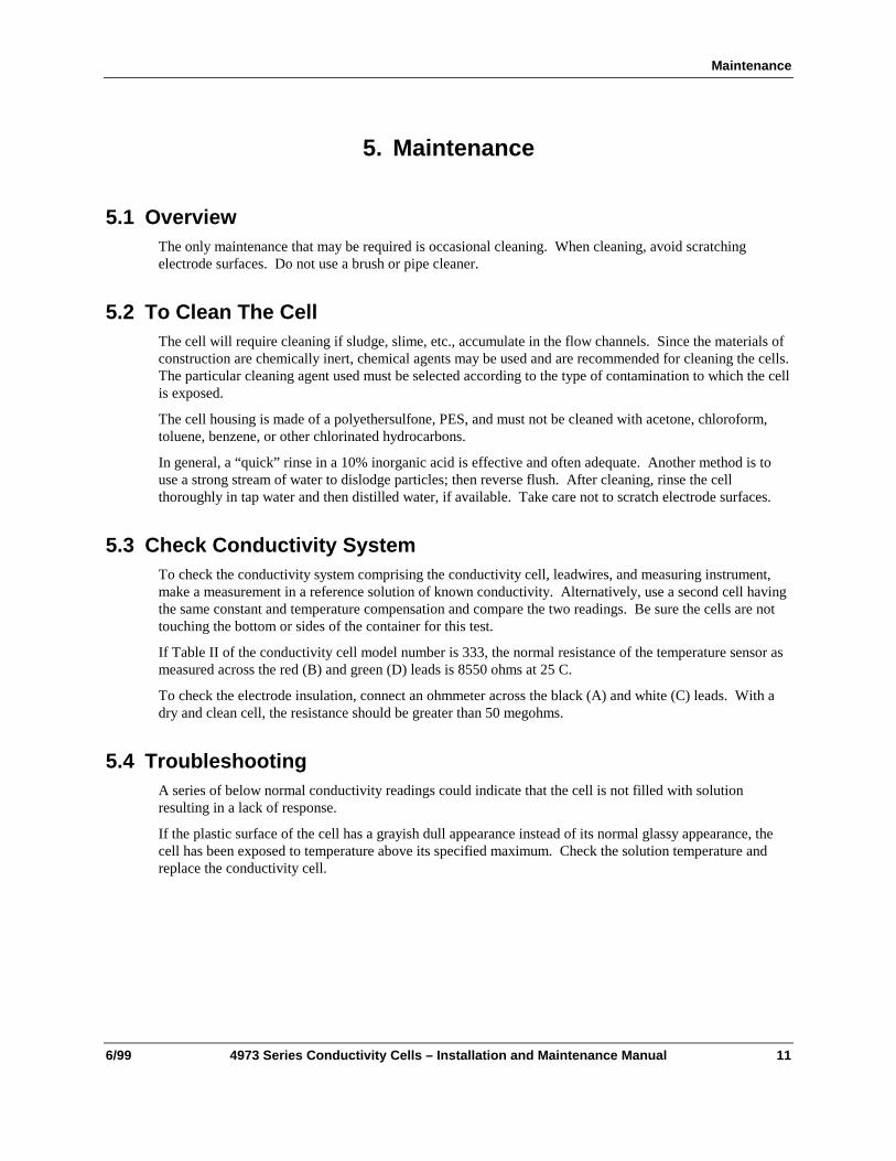
5.1 OverviewThe only maintenance that may be required is occasional cleaning. When cleaning, avoid scratchingelectrode surfaces. Do not use a brush or pipe cleaner.
5.2 To Clean The CellThe cell will require cleaning if sludge, slime, etc., accumulate in the flow channels. Since the materials ofconstruction are chemically inert, chemical agents may be used and are recommended for cleaning the cells.The particular cleaning agent used must be selected according to the type of contamination to which the cellis exposed.
The cell housing is made of a polyethersulfone, PES, and must not be cleaned with acetone, chloroform,toluene, benzene, or other chlorinated hydrocarbons.
In general, a “quick” rinse in a 10% inorganic acid is effective and often adequate. Another method is touse a strong stream of water to dislodge particles; then reverse flush. After cleaning, rinse the cellthoroughly in tap water and then distilled water, if available. Take care not to scratch electrode surfaces.
5.3 Check Conductivity SystemTo check the conductivity system comprising the conductivity cell, leadwires, and measuring instrument,make a measurement in a reference solution of known conductivity. Alternatively, use a second cell havingthe same constant and temperature compensation and compare the two readings. Be sure the cells are nottouching the bottom or sides of the container for this test.
If Table II of the conductivity cell model number is 333, the normal resistance of the temperature sensor asmeasured across the red (B) and green (D) leads is 8550 ohms at 25 C.
To check the electrode insulation, connect an ohmmeter across the black (A) and white (C) leads. With adry and clean cell, the resistance should be greater than 50 megohms.
5.4 TroubleshootingA series of below normal conductivity readings could indicate that the cell is not filled with solutionresulting in a lack of response.
If the plastic surface of the cell has a grayish dull appearance instead of its normal glassy appearance, thecell has been exposed to temperature above its specified maximum. Check the solution temperature andreplace the conductivity cell.
4973 Series Conductivity Cells Installation and Maintenance Manual
12 4973 Series Conductivity Cells – Installation and Maintenance Manual 6/99
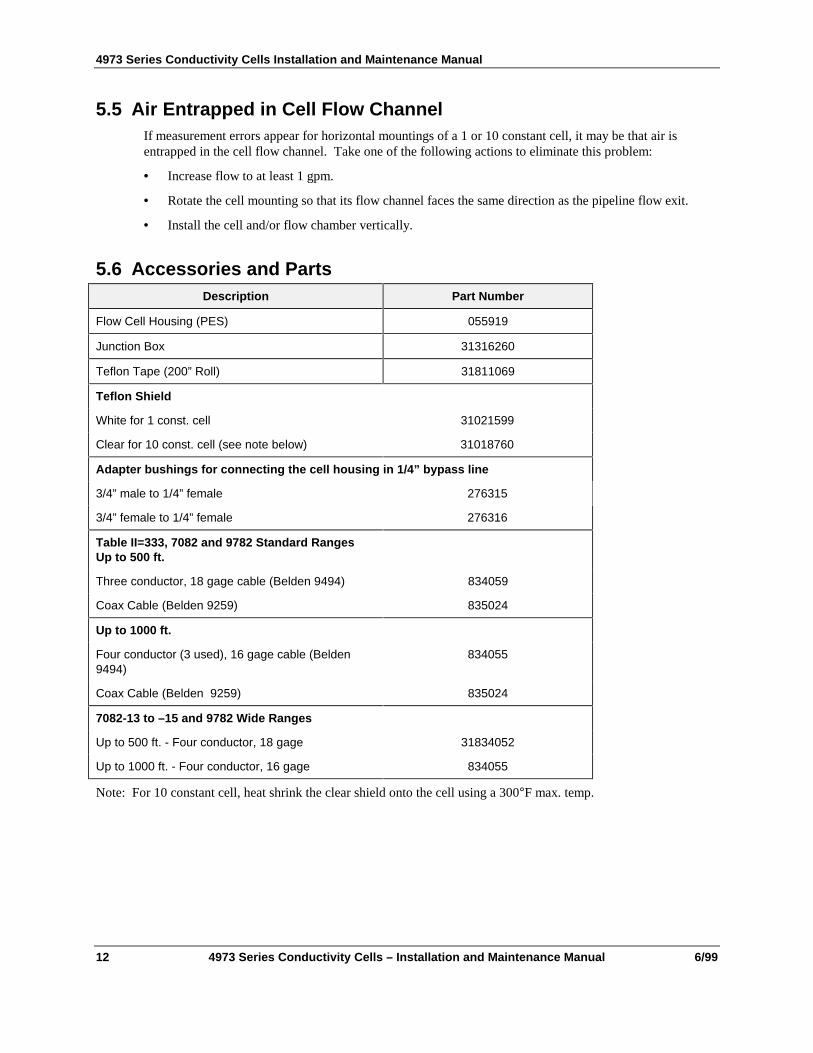
5.5 Air Entrapped in Cell Flow ChannelIf measurement errors appear for horizontal mountings of a 1 or 10 constant cell, it may be that air isentrapped in the cell flow channel. Take one of the following actions to eliminate this problem:
• Increase flow to at least 1 gpm.
• Rotate the cell mounting so that its flow channel faces the same direction as the pipeline flow exit.
• Install the cell and/or flow chamber vertically.
5.6 Accessories and PartsDescription Part Number
Flow Cell Housing (PES) 055919
Junction Box 31316260
Teflon Tape (200” Roll) 31811069
Teflon Shield
White for 1 const. cell 31021599
Clear for 10 const. cell (see note below) 31018760
Adapter bushings for connecting the cell housing in 1/4” bypass line
3/4” male to 1/4” female 276315
3/4” female to 1/4” female 276316
Table II=333, 7082 and 9782 Standard RangesUp to 500 ft.
Three conductor, 18 gage cable (Belden 9494) 834059
Coax Cable (Belden 9259) 835024
Up to 1000 ft.
Four conductor (3 used), 16 gage cable (Belden9494)
834055
Coax Cable (Belden 9259) 835024
7082-13 to –15 and 9782 Wide Ranges
Up to 500 ft. - Four conductor, 18 gage 31834052
Up to 1000 ft. - Four conductor, 16 gage 834055
Note: For 10 constant cell, heat shrink the clear shield onto the cell using a 300°F max. temp.
Maintenance
6/99 4973 Series Conductivity Cells – Installation and Maintenance Manual 13
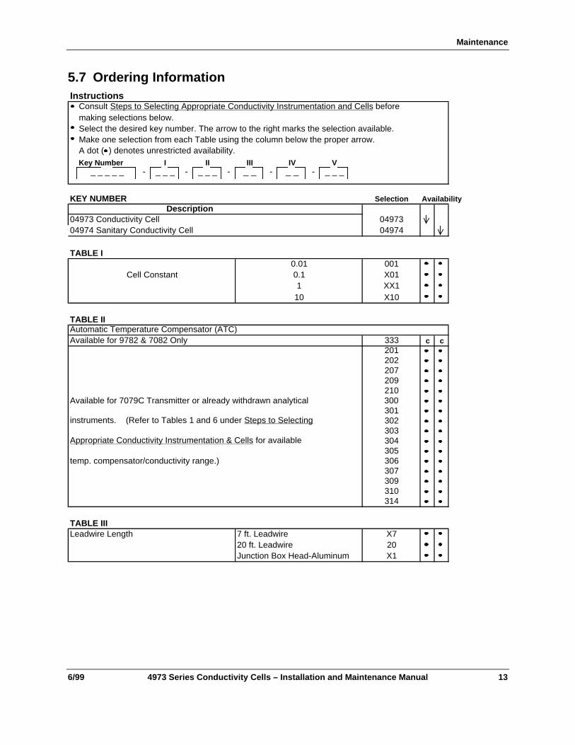
5.7 Ordering InformationInstructions
Consult Steps to Selecting Appropriate Conductivity Instrumentation and Cells beforemaking selections below.Select the desired key number. The arrow to the right marks the selection available.Make one selection from each Table using the column below the proper arrow.A dot ( ) denotes unrestricted availability.Key Number I II III IV V
_ _ _ _ _ - _ _ _ - _ _ _ - _ _ - _ _ - _ _ _
KEY NUMBER Selection AvailabilityDescription
04973 Conductivity Cell 0497304974 Sanitary Conductivity Cell 04974
TABLE I0.01 001
Cell Constant 0.1 X011 XX1
10 X10
TABLE IIAutomatic Temperature Compensator (ATC)Available for 9782 & 7082 Only 333 c c
201202207209210
Available for 7079C Transmitter or already withdrawn analytical 300301
instruments. (Refer to Tables 1 and 6 under Steps to Selecting 302303
Appropriate Conductivity Instrumentation & Cells for available 304305
temp. compensator/conductivity range.) 306307309310314
TABLE IIILeadwire Length 7 ft. Leadwire X7
20 ft. Leadwire 20Junction Box Head-Aluminum X1
4973 Series Conductivity Cells Installation and Maintenance Manual
14 4973 Series Conductivity Cells – Installation and Maintenance Manual 6/99
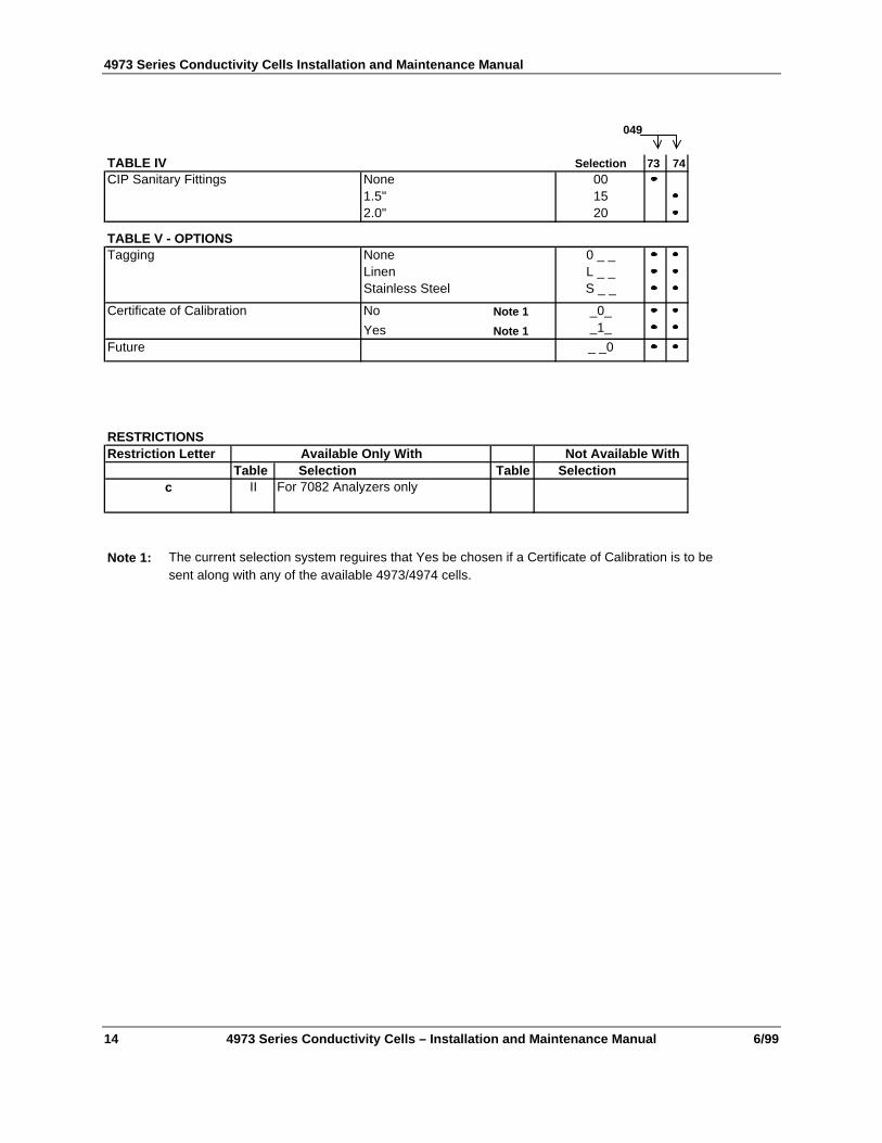
049
TABLE IV Selection 73 74CIP Sanitary Fittings None 00
1.5" 152.0" 20
TABLE V - OPTIONSTagging None 0 _ _
Linen L _ _Stainless Steel S _ _
Certificate of Calibration No Note 1 _0_
Yes Note 1 _1_
Future _ _0
RESTRICTIONSRestriction Letter Available Only With Not Available With
Table Selection Table Selectionc II For 7082 Analyzers only
Note 1: The current selection system reguires that Yes be chosen if a Certificate of Calibration is to be sent along with any of the available 4973/4974 cells.
Maintenance
6/99 4973 Series Conductivity Cells – Installation and Maintenance Manual 15
CELL
IN
1 1/2"(38mm)
8 3/4"(222mm)
14 1/2" max(368mm)
3/4" Fitting
Allow 4 1/8" (105mm) for removal of cell
3/4" NPT(Male)
Flow InFlow Chamber
1 1/2"(38mm)Octagon
3/4" NPT (Female)Flow Out
1 1/2"(38mm)
1 1/ 8"(38mm)
Hexagon
2" min.(51mm)C
ELL
IN
RED
WHITE
BLACKLinear Micromho,
Resistivity, orConcentration Ranges
Temp.Comp.
Cell
RED
WHITE
BLACK
ShuntComp.
SeriesComp.
Cell
Non-LinearMicromho Ranges
WHITE
BLACK
RED
GREEN
Cell
Temp.Comp.
Linear Ranges(Table II = 333 Only)
Cell Wiring
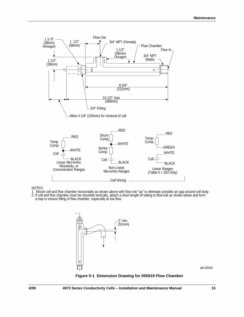
NOTES:1. Mount cell and flow chamber horizontally as shown above with flow exit "up" to eliminate possible air gap around cell body.2. If cell and flow chamber must be mounted vertically, attach a short length of tubing to flow exit as shown below and form a trap to ensure filling of flow chamber, especially at low flow.
a/n 23342
Figure 5-1 Dimension Drawing for 055919 Flow Chamber
4973 Series Conductivity Cells Installation and Maintenance Manual
16 4973 Series Conductivity Cells – Installation and Maintenance Manual 6/99
Table I0.01
0.11.010
Inch3.32.63.53.5
mm84668989
Dim "X"
3"(76mm)
1/2" female NPT for user’sflexible electrical conduit
connection. For insertion orremoval of cell, disconnect
conduit connections.
"X"See Table
5.875"(149.2mm)
Four Point TerminalBoard for lead wireconnections. Each #6-32screw terminal willaccomodate one#12 or smaller AWG wire
0.593" Dia.(15mm)
3/4" NPT
1.13" Hex(29mm)
RED
WHITE
BLACKLinear Micromho,
Resistivity, orConcentration Ranges
Temp.Comp.
Cell
RED
WHITE
BLACK
ShuntComp.
SeriesComp.
Cell
Non-LinearMicromho Ranges
WHITE
BLACK
RED
GREEN
Cell
Temp.Comp.
Linear Ranges(Table II = 333 Only)
Cell Wiring
a/n 23343
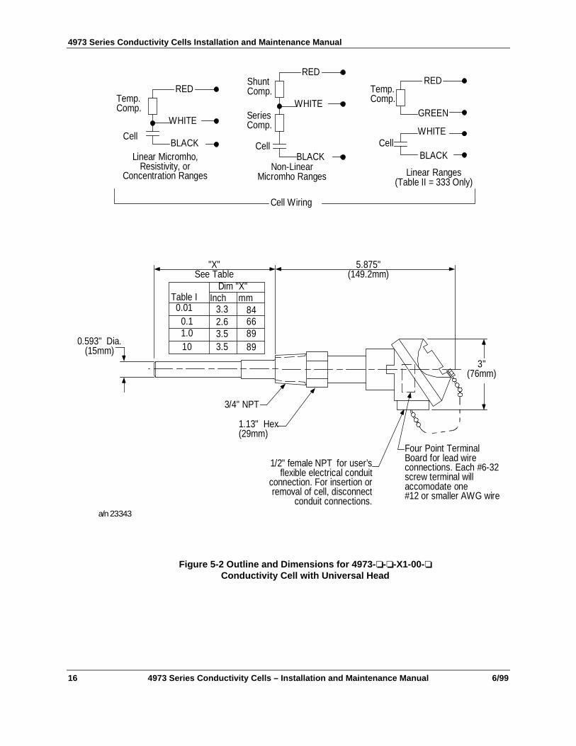
Figure 5-2 Outline and Dimensions for 4973-❏-❏-X1-00-❏Conductivity Cell with Universal Head
Maintenance
6/99 4973 Series Conductivity Cells – Installation and Maintenance Manual 17
"Z" "Y"
"X"See Table
2.771" ±.035(154mm ±.889)
±0.031(±0.787)
1 .1" Dia.(27.9mm)
Cable is approx. 0.250" (6.4mm)O.D. with 3 or 4 conductors of#18 AWG wire. (Table IIIdesignates cable lengths.)
3/4" NPT
1.13" Hex(29mm)
Suffix A00.10.11.010
Inch3.32.63.5
3.5
mm84668989
Inch.703.703.593
.593
mm17.8517.85
1 5.061 5.06
Inch.542.542.625
.564
mm13.7613.7615.8714.32
Dim "X" Dim "Y" Dim "Z"
RED
WHITE
BLACKLinear Micromho,
Resistivity, orConcentration Ranges
Temp.Comp.
Cell
RED
WHITE
BLACK
ShuntComp.
SeriesComp.
Cell
Non-LinearMicromho Ranges
WHITE
BLACK
RED
GREEN
Cell
Temp.Comp.
Linear Ranges
Cell Wiring
a/n 23344
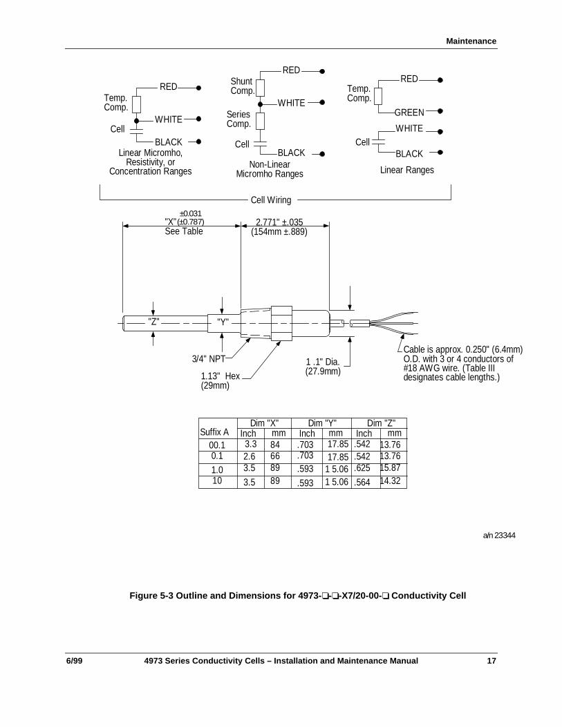
Figure 5-3 Outline and Dimensions for 4973-❏-❏-X7/20-00-❏ Conductivity Cell
4973 Series Conductivity Cells Installation and Maintenance Manual
18 4973 Series Conductivity Cells – Installation and Maintenance Manual 6/99
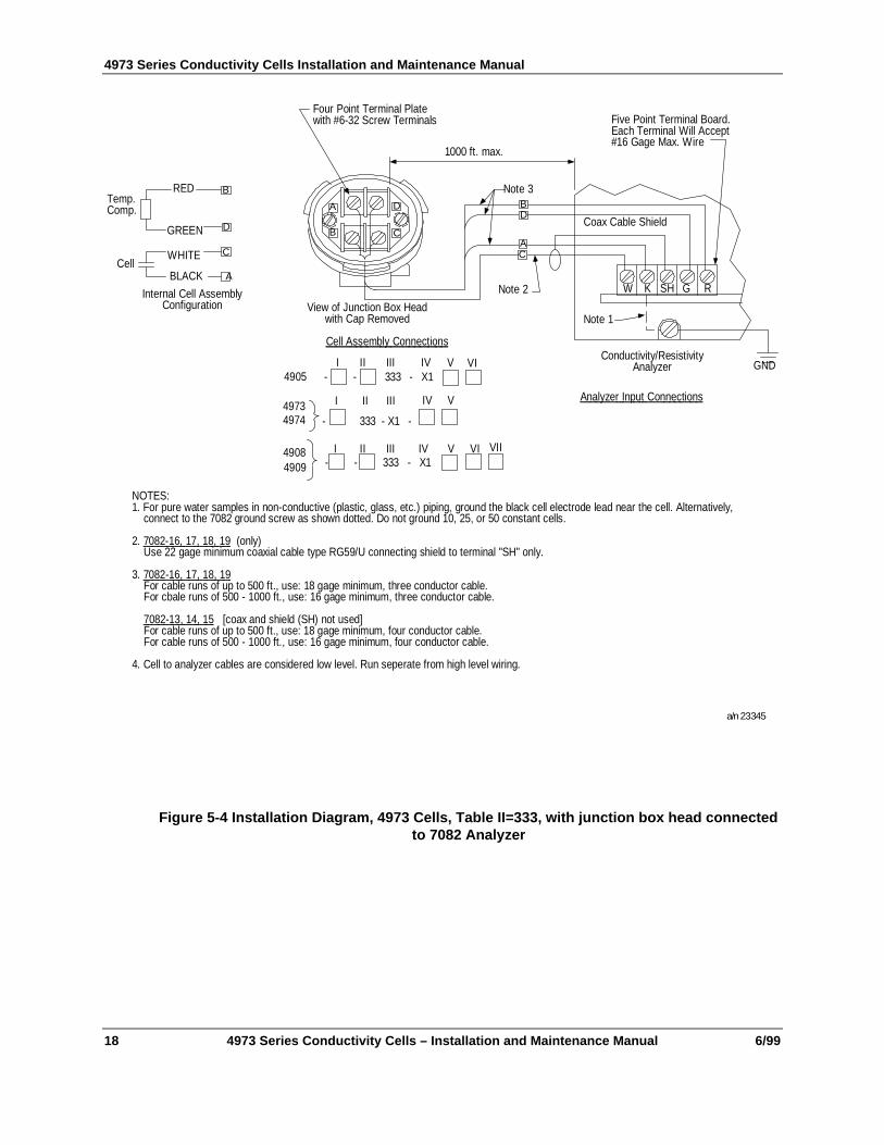
A D
CB
View of Junction Box Headwith Cap Removed
WHITE
BLACK
RED
GREEN
Cell
Temp.Comp.
B
D
C
A
Internal Cell AssemblyConfiguration
W K SH G R
Coax Cable Shield
Conductivity/ResistivityAnalyzer
An a l y ze r I np u t C on n e c ti o n s
BD
AC
1000 ft. max.
Note 3
Note 2
Four Point Terminal Platewith #6-32 Screw Terminals
Ce l l A s s e mb l y Co n n e ct i o n s
4905I II III IV V VI
- - 333 - X1
49734974
I II III IV
- 333 - X1 -
V
4908 I II III IV V VI- - 333 - X14909
VII
Five Point Terminal Board.Each Terminal Will Accept#16 Gage Max. Wire
Note 1
GND
NOTES:1. For pure water samples in non-conductive (plastic, glass, etc.) piping, ground the black cell electrode lead near the cell. Alternatively, connect to the 7082 ground screw as shown dotted. Do not ground 10, 25, or 50 constant cells.
2. 70 8 2- 1 6, 17 , 1 8 , 1 9 (only) Use 22 gage minimum coaxial cable type RG59/U connecting shield to terminal "SH" only.
3. 70 8 2 -1 6 , 1 7 , 1 8 , 1 9 For cable runs of up to 500 ft., use: 18 gage minimum, three conductor cable. For cbale runs of 500 - 1000 ft., use: 16 gage minimum, three conductor cable.
7 08 2 -1 3 , 14 , 1 5 [coax and shield (SH) not used] For cable runs of up to 500 ft., use: 18 gage minimum, four conductor cable. For cable runs of 500 - 1000 ft., use: 16 gage minimum, four conductor cable.
4. Cell to analyzer cables are considered low level. Run seperate from high level wiring.
a/n 23345
Figure 5-4 Installation Diagram, 4973 Cells, Table II=333, with junction box head connectedto 7082 Analyzer
Maintenance
6/99 4973 Series Conductivity Cells – Installation and Maintenance Manual 19
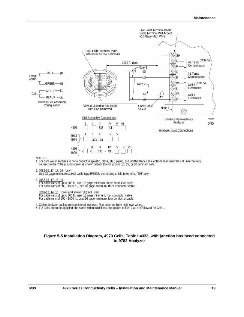
A
A D
CB
View of Junction Box Headwith Cap Removed
WHITE
BLACK
RED
GREEN
Cell
Temp.Comp.
B
D
C
A
Internal Cell AssemblyConfiguration
W
K
SH
G
R
Coax CableShield
Conductivity/ResistivityAnalyzer
An a l y ze r I np u t C on n e c ti o n s
B
C
1000 ft. max.Note 3
Note 2
Four Point Terminal Platewith #6-32 Screw Terminals
Five Point Terminal Board.Each Terminal Will Accept#16 Gage Max. Wire
Note 1
GND
NOTES:1. For pure water samples in non-conductive (plastic, glass, etc.) piping, ground the black cell electrode lead near the cell. Alternatively, connect to the 7082 ground screw as shown dotted. Do not ground 10, 25, or 50 constant cells.
2. 70 8 2- 1 6, 17 , 1 8 , 1 9 (only) Use 22 gage minimum coaxial cable type RG59/U connecting shield to terminal "SH" only.
3. 70 8 2 -1 6 , 1 7 , 1 8 , 1 9 For cable runs of up to 500 ft., use: 18 gage minimum, three conductor cable. For cable runs of 500 - 1000 ft., use: 16 gage minimum, three conductor cable.
7 08 2 -1 3 , 14 , 1 5 [coax and shield (SH) not used] For cable runs of up to 500 ft., use: 18 gage minimum, four conductor cable. For cable runs of 500 - 1000 ft., use: 16 gage minimum, four conductor cable.
4. Cell to analyzer cables are considered low level. Run seperate from high level wiring.5. If 2 Cells are to be appplied, the same wiring guidelines are applied to Cell 2 as are followed for Cell 1.
Ce l l A s s e mb l y Co n n e ct i o n s
4905I II III IV V VI
- - 333 - X1
49734974
I II III IV
- 333 - X1 -
V
4908 I II III IV V VI- - 333 - X14909
VII
K
W
G
R
#2 TempCompensator
#1 TempCompensator
Cell 2Electrodes
Cell 1Electrodes
D
(Note 5)
(Note 5)
Figure 5-5 Installation Diagram, 4973 Cells, Table II=333, with junction box head connectedto 9782 Analyzer
4973 Series Conductivity Cells Installation and Maintenance Manual
20 4973 Series Conductivity Cells – Installation and Maintenance Manual 6/99
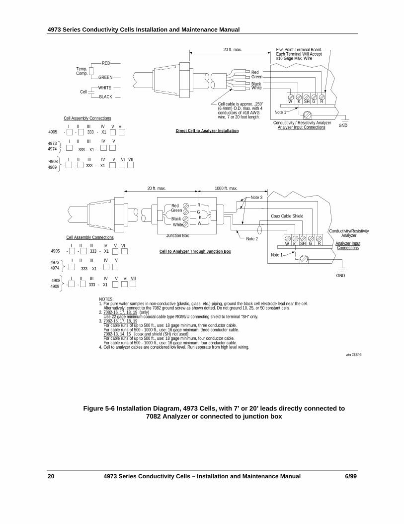
WHITE
BLACK
RED
GREEN
Cell
Temp.Comp.
W K SH G R
Five Point Terminal Board.Each Terminal Will Accept#16 Gage Max. Wire
Note 1
GNDConductivity / Resistivity Analyzer
An a l y ze r I np u t C on n e c ti o n s
20 ft. max.
RedGreen
BlackWhite
Cell cable is approx. .250"(6.4mm) O.D. max. with 4conductors of #18 AWGwire, 7 or 20 foot length.
D i r e c t C e l l t o A n a l y z e r I n s t a l l a t i o n
NOTES:1. For pure water samples in non-conductive (plastic, glass, etc.) piping, ground the black cell electrode lead near the cell. Alternatively, connect to the 7082 ground screw as shown dotted. Do not ground 10, 25, or 50 constant cells.2. 70 8 2- 1 6, 17 , 1 8 , 1 9 (only) Use 22 gage minimum coaxial cable type RG59/U connecting shield to terminal "SH" only.3. 70 8 2 -1 6 , 1 7 , 1 8 , 1 9 For cable runs of up to 500 ft., use: 18 gage minimum, three conductor cable. For cable runs of 500 - 1000 ft., use: 16 gage minimum, three conductor cable. 7 08 2 -1 3 , 14 , 1 5 [coax and shield (SH) not used] For cable runs of up to 500 ft., use: 18 gage minimum, four conductor cable. For cable runs of 500 - 1000 ft., use: 16 gage minimum, four conductor cable.4. Cell to analyzer cables are considered low level. Run seperate from high level wiring.
W K SH G R
Conductivity/ResistivityAnalyzer
An a l y z e r I n p u t Co n n e c t i on s
1000 ft. max.
Note 1
GND
RedGreen
BlackWhite
R
GK
W
20 ft. max.
Coax Cable Shield
Junction Box
Note 3
Note 2
C e l l t o A n a l y z e r T h r o u g h J u n c t i o n B o x
a/n 23346
Ce l l A s s e mb l y Co n n e ct i o n s
4905I II III IV V VI
- - 333 - X1
49734974
I II III IV
- 333 - X1 -
V
4908 I II III IV V VI- - 333 - X14909
VII
Ce l l A s s e mb l y Co n n e ct i o n s
4905I II III IV V VI
- - 333 - X1
49734974
I II III IV
- 333 - X1 -
V
4908 I II III IV V VI- - 333 - X14909
VII
Figure 5-6 Installation Diagram, 4973 Cells, with 7’ or 20’ leads directly connected to7082 Analyzer or connected to junction box
Maintenance
6/99 4973 Series Conductivity Cells – Installation and Maintenance Manual 21
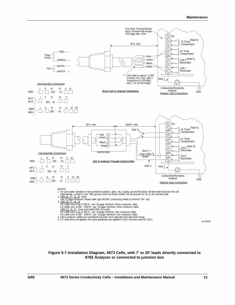
WHITE
BLACK
RED
GREEN
Cell
Temp.Comp.
W
K
SH
G
R
Conductivity/ResistivityAnalyzer
Note 1
GND
K
W
G
R
#2 TempCompensator
#1 TempCompensator
Cell 2Electrodes
Cell 1Electrodes
(Note 5)
(Note 5)
Five Point Terminal Board.Each Terminal Will Accept#16 Gage Max. Wire
An a l y ze r I np u t C on n e c ti o n s
20 ft. max.
RedGreenBlackWhite
Cell cable is approx. 0.250"(6.4mm) O.D. max. with 4conductors of #18 AWGwire, 7 or 20 foot length.
D i r e c t C e l l t o A n a l y z e r I n s t a l l a t i o n
NOTES:1. For pure water samples in non-conductive (plastic, glass, etc.) piping, ground the black cell electrode lead near the cell. Alternatively, connect to the 7082 ground screw as shown dotted. Do not ground 10, 25, or 50 constant cells.2. 70 8 2- 1 6, 17 , 1 8 , 1 9 (only) Use 22 gage minimum coaxial cable type RG59/U connecting shield to terminal "SH" only.3. 70 8 2 -1 6 , 1 7 , 1 8 , 1 9 For cable runs of up to 500 ft., use: 18 gage minimum, three conductor cable. For cbale runs of 500 - 1000 ft., use: 16 gage minimum, three conductor cable. 7 08 2 -1 3 , 14 , 1 5 [coax and shield (SH) not used] For cable runs of up to 500 ft., use: 18 gage minimum, four conductor cable. For cable runs of 500 - 1000 ft., use: 16 gage minimum, four conductor cable.4. Cell to analyzer cables are considered low level. Run seperate from high level wiring.5. If 2 Cells are to be applied, the same guidelines are applied to Cell 2 as were used for Cell 1.
An a l y ze r I np u t C on n e c ti o n s
1000 ft. max.
RedGreen
BlackWhite
R
GKW
20 ft. max.
Coax CableShield
Junction Box
Note 3
Note 2
C e l l t o A n a l y z e r T h r o u g h J u n c t i o n B o x
a/n 23346
Ce l l A s s e mb l y Co n n e ct i o n s
4905I II III IV V VI
- - 333 - X1
49734974
I II III IV
- 333 - X1 -
V
4908 I II III IV V VI- - 333 - X14909
VII
Ce l l A s s e mb l y Co n n e ct i o n s
4905I II III IV V VI
- - 333 - X1
49734974
I II III IV
- 333 - X1 -
V
4908 I II III IV V VI- - 333 - X14909
VII
W
K
SH
G
R
Conductivity/ResistivityAnalyzer
Note 1
GND
K
W
G
R
#2 TempCompensator
#1 TempCompensator
Cell 2Electrodes
Cell 1Electrodes
(Note 5)
(Note 5)
Note 3
Figure 5-7 Installation Diagram, 4973 Cells, with 7’ or 20’ leads directly connected to9782 Analyzer or connected to junction box
4973 Series Conductivity Cells Installation and Maintenance Manual
22 4973 Series Conductivity Cells – Installation and Maintenance Manual 6/99


Industrial Automation and Control Helping You Control Your WorldHoneywell, Inc.1100 Virginia DriveFort Washington, Pennsylvania 19034