4c22c cpu manual - mesanet.com · · 2003-07-29cpu operation power consumption ... c. ground...
TRANSCRIPT

4C22C CPU MANUALVERSION 1.6
Copyright 1997 by MESA ELECTRONICS Richmond, CA. Printed in the United States ofAmerica. All rights reserved. This document and the data disclosed herein is not to be reproduced,used, disclosed in whole or in part to anyone without the written permission of MESAELECTRONICS.
Mesa Electronics
4175 Lakeside Drive, Suite #100Richmond, CA 94806-1950
Tel (510) 223-9272 - Fax (510) 223-9585E-Mail: [email protected] - Website: www.mesanet.com
4 C 2 2 U S E R S M A N U A L

4 C 2 2 U S E R S M A N U A L

TABLE OF CONTENTS
HANDLING PRECAUTIONS
Lithium cell 5. . . . . . . . . . . . . . . . . . . . . . . . . . . . . . . . . . . . . . . . . . . . . . . . . . . . . . . . . . . . . . . . . . . . . . . . . . . .Static electricity 5. . . . . . . . . . . . . . . . . . . . . . . . . . . . . . . . . . . . . . . . . . . . . . . . . . . . . . . . . . . . . . . . . . . . . . . .
INTRODUCTION
General 7. . . . . . . . . . . . . . . . . . . . . . . . . . . . . . . . . . . . . . . . . . . . . . . . . . . . . . . . . . . . . . . . . . . . . . . . . . . . . . . .
CONFIGURATION General 8. . . . . . . . . . . . . . . . . . . . . . . . . . . . . . . . . . . . . . . . . . . . . . . . . . . . . . . . . . . . . . . . . . . . . . . . . . . . . . .Default jumper settings 8. . . . . . . . . . . . . . . . . . . . . . . . . . . . . . . . . . . . . . . . . . . . . . . . . . . . . . . . . . . . . . . .Disk emulator type selection 10. . . . . . . . . . . . . . . . . . . . . . . . . . . . . . . . . . . . . . . . . . . . . . . . . . . . . . . . . .LCD DMA rate 12. . . . . . . . . . . . . . . . . . . . . . . . . . . . . . . . . . . . . . . . . . . . . . . . . . . . . . . . . . . . . . . . . . . . . . .COM2/4 port emulation 14. . . . . . . . . . . . . . . . . . . . . . . . . . . . . . . . . . . . . . . . . . . . . . . . . . . . . . . . . . . . . .Lithium cell enable 14. . . . . . . . . . . . . . . . . . . . . . . . . . . . . . . . . . . . . . . . . . . . . . . . . . . . . . . . . . . . . . . . . . . .
CONNECTORS
Power connector 16. . . . . . . . . . . . . . . . . . . . . . . . . . . . . . . . . . . . . . . . . . . . . . . . . . . . . . . . . . . . . . . . . . . . . .Keyboard connector 16. . . . . . . . . . . . . . . . . . . . . . . . . . . . . . . . . . . . . . . . . . . . . . . . . . . . . . . . . . . . . . . . . .Serial port connector 17. . . . . . . . . . . . . . . . . . . . . . . . . . . . . . . . . . . . . . . . . . . . . . . . . . . . . . . . . . . . . . . . . .LCD-Keypad connector 19. . . . . . . . . . . . . . . . . . . . . . . . . . . . . . . . . . . . . . . . . . . . . . . . . . . . . . . . . . . . . .
INSTALLATION
General 21. . . . . . . . . . . . . . . . . . . . . . . . . . . . . . . . . . . . . . . . . . . . . . . . . . . . . . . . . . . . . . . . . . . . . . . . . . . . . . .I/O connector orientation 21. . . . . . . . . . . . . . . . . . . . . . . . . . . . . . . . . . . . . . . . . . . . . . . . . . . . . . . . . . . . .
CPU OPERATIONPower consumption 22. . . . . . . . . . . . . . . . . . . . . . . . . . . . . . . . . . . . . . . . . . . . . . . . . . . . . . . . . . . . . . . . . . .Hardware tic clock 22. . . . . . . . . . . . . . . . . . . . . . . . . . . . . . . . . . . . . . . . . . . . . . . . . . . . . . . . . . . . . . . . . . . .Watchdog timer 22. . . . . . . . . . . . . . . . . . . . . . . . . . . . . . . . . . . . . . . . . . . . . . . . . . . . . . . . . . . . . . . . . . . . . . .Serial port 22. . . . . . . . . . . . . . . . . . . . . . . . . . . . . . . . . . . . . . . . . . . . . . . . . . . . . . . . . . . . . . . . . . . . . . . . . . . . .COM4 port emulation 23. . . . . . . . . . . . . . . . . . . . . . . . . . . . . . . . . . . . . . . . . . . . . . . . . . . . . . . . . . . . . . . .RS-232 / RS-485 operation 23. . . . . . . . . . . . . . . . . . . . . . . . . . . . . . . . . . . . . . . . . . . . . . . . . . . . . . . . . . .Serial file download 24. . . . . . . . . . . . . . . . . . . . . . . . . . . . . . . . . . . . . . . . . . . . . . . . . . . . . . . . . . . . . . . . . . .Console switching 26. . . . . . . . . . . . . . . . . . . . . . . . . . . . . . . . . . . . . . . . . . . . . . . . . . . . . . . . . . . . . . . . . . . .Extended INT 1A functions 27. . . . . . . . . . . . . . . . . . . . . . . . . . . . . . . . . . . . . . . . . . . . . . . . . . . . . . . . . . .Setup storage 29. . . . . . . . . . . . . . . . . . . . . . . . . . . . . . . . . . . . . . . . . . . . . . . . . . . . . . . . . . . . . . . . . . . . . . . . .Disk emulator 30. . . . . . . . . . . . . . . . . . . . . . . . . . . . . . . . . . . . . . . . . . . . . . . . . . . . . . . . . . . . . . . . . . . . . . . . .
4C22C CPU USER'S MANUAL

TABLE OF CONTENTS
LCD OPERATION
General 32. . . . . . . . . . . . . . . . . . . . . . . . . . . . . . . . . . . . . . . . . . . . . . . . . . . . . . . . . . . . . . . . . . . . . . . . . . . . . . .System resources needed 32. . . . . . . . . . . . . . . . . . . . . . . . . . . . . . . . . . . . . . . . . . . . . . . . . . . . . . . . . . . . .Text mode 32. . . . . . . . . . . . . . . . . . . . . . . . . . . . . . . . . . . . . . . . . . . . . . . . . . . . . . . . . . . . . . . . . . . . . . . . . . . .Text Fonts 33. . . . . . . . . . . . . . . . . . . . . . . . . . . . . . . . . . . . . . . . . . . . . . . . . . . . . . . . . . . . . . . . . . . . . . . . . . . .Text screen sizes 33. . . . . . . . . . . . . . . . . . . . . . . . . . . . . . . . . . . . . . . . . . . . . . . . . . . . . . . . . . . . . . . . . . . . . .Text attributes 33. . . . . . . . . . . . . . . . . . . . . . . . . . . . . . . . . . . . . . . . . . . . . . . . . . . . . . . . . . . . . . . . . . . . . . . .Text window 34. . . . . . . . . . . . . . . . . . . . . . . . . . . . . . . . . . . . . . . . . . . . . . . . . . . . . . . . . . . . . . . . . . . . . . . . . .Graphics 35. . . . . . . . . . . . . . . . . . . . . . . . . . . . . . . . . . . . . . . . . . . . . . . . . . . . . . . . . . . . . . . . . . . . . . . . . . . . . .Extended INT 10 functions 35. . . . . . . . . . . . . . . . . . . . . . . . . . . . . . . . . . . . . . . . . . . . . . . . . . . . . . . . . . .LCD types 40. . . . . . . . . . . . . . . . . . . . . . . . . . . . . . . . . . . . . . . . . . . . . . . . . . . . . . . . . . . . . . . . . . . . . . . . . . . .LCD Power supply 43. . . . . . . . . . . . . . . . . . . . . . . . . . . . . . . . . . . . . . . . . . . . . . . . . . . . . . . . . . . . . . . . . . . .Demonstration Programs 43. . . . . . . . . . . . . . . . . . . . . . . . . . . . . . . . . . . . . . . . . . . . . . . . . . . . . . . . . . . . .MINT 44. . . . . . . . . . . . . . . . . . . . . . . . . . . . . . . . . . . . . . . . . . . . . . . . . . . . . . . . . . . . . . . . . . . . . . . . . . . . . . . . .PCX2HEX 45. . . . . . . . . . . . . . . . . . . . . . . . . . . . . . . . . . . . . . . . . . . . . . . . . . . . . . . . . . . . . . . . . . . . . . . . . . . .
KEYPAD OPERATION
General 46. . . . . . . . . . . . . . . . . . . . . . . . . . . . . . . . . . . . . . . . . . . . . . . . . . . . . . . . . . . . . . . . . . . . . . . . . . . . . . .DISPKEYS 46. . . . . . . . . . . . . . . . . . . . . . . . . . . . . . . . . . . . . . . . . . . . . . . . . . . . . . . . . . . . . . . . . . . . . . . . . . .
REFERENCE INFORMATION
Specifications 47. . . . . . . . . . . . . . . . . . . . . . . . . . . . . . . . . . . . . . . . . . . . . . . . . . . . . . . . . . . . . . . . . . . . . . . . .Warranty 48. . . . . . . . . . . . . . . . . . . . . . . . . . . . . . . . . . . . . . . . . . . . . . . . . . . . . . . . . . . . . . . . . . . . . . . . . . . . . .Schematic diagrams 49. . . . . . . . . . . . . . . . . . . . . . . . . . . . . . . . . . . . . . . . . . . . . . . . . . . . . . . . . . . . . . . . . . .Mechanical drawings XX. . . . . . . . . . . . . . . . . . . . . . . . . . . . . . . . . . . . . . . . . . . . . . . . . . . . . . . . . . . . . . . .
4C22C CPU USER'S MANUAL

4C22C CPU USER'S MANUAL

HANDLING PRECAUTIONS
4C22C CPU USER'S MANUAL
LITHIUM CELL
The 4C22 CPU card contains a lithium cell which can create a fire orexplosion hazard if improperly handled.
Do not expose battery to temperatures in excess of 100 degrees Celsius ordispose of in fire.
Do not attempt to charge battery or modify battery related circuitry on the4C22.
Do not short circuit battery (take care not to set the 4C22 on conductive
STATIC ELECTRICITY The CMOS integrated circuits on the 4C22 can be damaged by exposure to
electrostatic discharges. The following precautions should be taken whenhandling the 4C22 to prevent possible damage.
A. Leave the 4C22 in its antistatic bag until needed. B. All work should be performed at an antistatic workstation. C. Ground equipment into which 4C22 will be installed. D. Ground handling personnel with conductive bracelet through 1 Meg resistor to ground.

INTRODUCTION
GENERAL
The 4C22 is a low power, all CMOS, XT compatible CPU implemented on the PC/104 bus. The4C22 is optimized for low cost, high integration, instrument and controller applications.
The 4C22 has built-in disk emulator with up to 2M byte capacity, a serial port, an LCD interface, astandard keyboard interface, and a keypad interface. The 4C22 uses a PC compatible 9.2 or 14.7 MHzV40 CPU with up to 640K bytes of system RAM.
The disk emulator consists of two 32 pin dip sockets Each socket can be configured to use batterybacked static RAM, 5V flash EEPROM or regular EPROM. One disk emulator socket is used forsystem RAM when the 4C22 is configured for 640K. The 4C22 BIOS fully supports the built-in diskemulator as a standard disk drive. The emulated drive is bootable and has with full compatibility withapplication and operating system software.
The RS-232 serial port uses the V40's built-in serial interface and supports baud rates up to115.2K. Higher baud rates match standard COMX port baud rates. The 4C22 has an optional RS-485interface to support multi drop applications.
The 4C22 can directly drive small graphic LCDs (up to 320 X 240 pixel). The 4C22 uses DMA togenerate the LCD control signals, which allows very flexible display control. The 4C22 BIOSimplements text and graphic output to the LCD display. Graphic support in the BIOS includesBitBLT, drawdot, and line drawing. A BGI driver is supplied to simplify writing graphic programsusing Borland compilers. The 4C22 has a built in LCD power supply (-5V to -18V) that is softwaresettable for LCD contrast adjustment. Variable backlight intensity is supported on some displays.
The 4C22 has hardware and BIOS support for scanning up to a 24 key keypad switch array. Thekeypad support in the BIOS makes the keypad switch array appear to the system as a standardkeyboard.
4C22C CPU USER'S MANUAL

HARDWARE CONFIGURATION
GENERAL
The 4C22 has a number of jumper selectable options that must be properly set to match the 4C22application. Each group of jumpers will be discussed separately by function. In the followingdiscussions, when the words "up", "down", "right", and "left" are used it is assumed that the 4C22CPU card is oriented with its bus connectors J1 and J2 at the bottom edge of the card (nearest theperson doing the configuration).
DEFAULT JUMPER SETTINGS
Factory default 4C22 jumpering is as follows:
FUNCTION JUMPER(S) SETTING
Disk emulator U11 W1,W2,W3,W4,W5 Flash EEPROM
Disk emulator U17 W6,W7,W8,W9,W10 Flash EEPROM
Lithium cell connect W11 Disabled
LCD DMA rate W12,W13,W15,W16 Lowest (W16)
COM2/4 emulate W14 Disabled
4C22C CPU USER'S MANUAL
Page 8

HARDWARE CONFIGURATION
DEFAULT JUMPERING
Page 9
4C22C CPU USER'S MANUAL

HARDWARE CONFIGURATION
DISK EMULATOR TYPE SELECTION
The 4C22 has two 32 pin sockets available disk emulator use. These sockets are the two uppersockets on the 4C22 (U11 and U17). The disk emulator can use battery backed RAM, EPROM, or 5Vflash EEPROM. Each socket can be configured independently. This allows the creation of dual drive(C: and D:) disk emulator systems using different memory technologies.
For example. A system could be configured with a 512K flash EEPROM disk for programstorage, and a 128K RAM disk for data collection. If both sockets use the same chip type, they can becombined into a single, larger disk emulator.
The 4C22 disk emulator hardware needs to be configured to match the memory type used. Twosets of five jumper blocks configure the memory type. Jumpers W1,W2,W3,W4, and W5 select U11'stype, while jumpers W6,W7,W8,W9,W10 select U17's type. These jumper blocks are all have threepins and 2 valid shorting jumper positions, left and right. The following table shows the jumpersetting for different disk emulator memory types:
MEMORY TYPE JUMPER POSITIONS
U11 type jumpers W1 W2 W3 W4 W5
U17 type jumpers W6 W7 W8 W9 W10
Flash EEPROM (Default) left left right left left
EPROM left left left left left
RAM right right right right right
For more information on disk emulator usage, see the CPU operation section of the manual
Page 10
4C22C CPU USER'S MANUAL

HARDWARE CONFIGURATION
DISK EMULATOR TYPE JUMPERS
Page 11
4C22C CPU USER'S MANUAL

HARDWARE CONFIGURATION
DISK EMULATOR TYPE JUMPERS
LCD DMA RATE The small LCD support logic on the 4C22 uses DMA channel 1 to drive theLCD panel. Differing LCD module sizes need differing DMA rates. If the DMA rate for a panel is tolow, visible flicker will be apparent. Setting the DMA rate too high will unnecessarily slow the CPU.The DMA rate is selected by moving a shorting jumper to one of three jumper blocks, W13,W15, orW16. Do not install more than one jumper. The following table shows appropriate DMA rates forvarious size display panels with the 9.2 MHz CPU.
SIZE JUMPER RATE LCD REFRESH OVERHEAD
128 X 64 W16 144 Kc 56 to 70 CPS 25%
240 X 64 W15 288 Kc 56 to 70 CPS 12.5%
256 X 64
240 X 128 W13 576 Kc 56 to 70 CPS 25%
256 X 128
480 X 64
640 X 64
The following table shows appropriate DMA rates for various size display panels with the 14.7MHz CPU.
SIZE JUMPER RATE LCD REFRESH OVERHEAD
128 X 64 W16 230 Kc 90 to 112 CPS 6.25%
240 X 64 W15 461 Kc 90 to 112 CPS 12.5%
256 X 64
240 X 128 W13 921 Kc 56 to 112 CPS 25%
256 X 128
480 X 64
480 X 128
320 X 240
For more information on LCD support, see the LCD OPERATION section of the manual.
Page 12
4C22C CPU USER'S MANUAL

HARDWARE CONFIGURATION
LCD DMA RATE JUMPERS
Page 13
4C22C CPU USER'S MANUAL

CPU OPERATION
COM2/4 EMULATION
The 4C22 uses the V40's built-in serial port. Unfortunately, this serial port hardware is notcompatible with the standard 8250 type PC serial ports. To compensate for this difference, the 4C22can emulate COM2 (Rev. A PC cards) or COM4 (Rev. B and later PC cards) via a I/O decodetriggered NMI (Non Maskable Interrupt) trap. This trap is enabled with jumper W14. When W14 is inthe up position, COM2 emulation is enabled. When W14 is in the down position, COM2 emulation isdisabled. COM2/4 port emulation must be disabled if external COM2 or COM4 ports are used.
LITHIUM CELL CONNECTThe 4C22's Lithium cell is disconnected for shipping and can be disconnected if long term storage
is planned. The cell should also be disconnected when battery backed disk emulator RAMs areinstalled or removed. To disconnect the Lithium cell from all 4C22 circuitry, remove the shortingjumper from jumper block W11. The shorting jumper can be left on one pin so that it doesn't becomelost. When W11 is removed, the TOD clock calendar forgets the time and date, and any data inRAM disk emulators will be lost!
Page 14
4C22C CPU USER'S MANUAL

HARDWARE CONFIGURATION
COM2 EMULATION AND LITHIUM CELL ENABLE JUMPERS
Page 15
4C22C CPU USER'S MANUAL

CONNECTORS
POWER CONNECTORThe 4C22 power connector (P2) is a 4 pin, single row, .1" header. The suggested mating
connector is an AMP MTA type connector 641190-4 (non-feedthrough) or 641198-4 (feedthrough).These are both gold plated type connectors. Power pin arrangement is +5V, gnd, gnd, +5V. This pin-out is compatible with newer (+5V only) 3.5 inch floppy drives.
Since the power connector on the 4C22 may well power the whole PC104 stack, it is suggestedthat only gold plated connectors be used. Tin plated connectors have a pronounced tendency to failover time via increased contact resistance when anywhere near their rated power is drawn.
Power connector pinout is as follows:
PIN SIGNAL CURRENT RATING
1 +5V 1A
2 GND 1A
3 GND 1A
4 +5V 1A The current ratings above mean that the total +5V current needs to be limited to 2A.
KEYBOARD CONNECTOR P4 is the XT keyboard, reset-in and speaker connector. P4 is a 10 pin dual row .1" header. The
suggested mating connector is AMP PN 499934-1. This is an IDC (flat cable) type connector. The XT keyboard interface on the 4C22 is intended mainly for development applications. The
keyboard interface will not work with AT type keyboards. An external reset switch input and speaker output are also available on P4. The reset circuit works
by grounding the EXTPF signal. The speaker output is intended to drive high impedance speakers (40ohms or more) . Eight Ohm speakers will be too quiet for most applications. The speaker output idlesat +5V so the speaker common is +5V. An external PNP transistor can be used to drive an eight Ohmspeaker to obnoxious volume levels if required.
Page 16
4C22C CPU USER'S MANUAL

CONNECTORS
KEYBOARD CONNECTOR
Keyboard connector pin-out is as follows:
PIN SIGNAL FUNCTION
1 KBCLK Clock from keyboard
2 KDATA Data from keyboard
3 KEY (Pin missing - key)
4 KGND Keyboard power return
5 KVCC Keyboard +5V power
6 NC (No Connection)
7 RGND Reset-in common (ground)
8 EXTPF Reset-in
9 SPKOUT Speaker output
10 SPKVCC Speaker common (+5V)
Notice that the first 5 signals match the signal order on the XT keyboard. If a flat cable is used, thefirst 5 wires can be split off for connection to the keyboard. If you make your own keyboard adaptercable, make sure you get the connections to the DIN connector correct (the pins on the DINconnector are not in ascending sequence) A keyboard adapter cable is available from MESA
SERIAL PORT CONNECTORP3 is the serial port connector P3 is a 10 pin dual row .1" header. The suggested mating connector
is AMP PN 499934-1. This is an IDC (flat cable) type connector. When the flat cable from P3 is terminated with a male 9 pin D type connector (suggested
connector AMP 747306-4), the 9 pin connector will have a similar pin-out to the AT type 9 pin serialport. The pin 10 wire must be stripped from the cable before installing the D connector. A foot longserial port adapter cable, and a five foot long download cable are available from MESA.
Page 17
4C22C CPU USER'S MANUAL

CONNECTORS
SERIAL PORT CONNECTOR
Serial port connector pin-out is as follows:
HDR PIN DSUB PIN SIGNAL FUNCTION
1 1 NC
2 6 DSR Handshake in
3 2 RXD Data in
4 7 RTS Handshake out
5 3 TXD Data out
6 8 485-A RS-485 I/O A
7 4 DTR Pullup on 4C22
8 9 485-B RS-485 I/O B
9 5 GND Signal ground
10 NC +5V +5V user power
NOTE: When the RS-485 option is installed (U29 installed), make sure that you do not connectany RS-232 signals to the RS-485 pins (6 and 8) or you may damage U29.
SERIAL PORT FLAT CABLE
Page 18
4C22C CPU USER'S MANUAL

CONNECTORS
LCD-KEYPAD CONNECTOR
P1 is the LCD module and key pad interface connector. P1 is a 26 pin 2 mm connector. Thesuggested mating connector is a Suyin 20042-26G2 or 3M 1522-0-110- GG. These are both IDCcable mount type connectors. Preterminated one ended flat cables are available from MESA ifrequired, as 2 mm cable and connectors are not very common yet.
Individual wire type 2 mm connectors are available, but are difficult to terminate, and ratherfragile. It is better to use an IDC type connector at the 4C22 end of the cable, and then split the flatcable wires if separate wires are needed
When connecting LCD modules for the first time, carefully check the power connections with avoltmeter before connecting the display. The 4C22 supports display modules with 4 data bits, CL1,CL2, FLM and M signals. LCD signal names are fairly standard, but check that the signal definitionsmatch those of your module before connecting.
LCD-KEYPAD (P1) connector pin-out is grouped into 2 sections, LCD and KEYPAD. First the LCD section:
PIN SIGNAL FUNCTION
1 GND. /BL PWM LCD power return / BL PWM (rev. C )
2 LCDON LCD +5 power
3 GND. LCD power return
4 LCDVEE LCD variable VEE power
5 CL1 LCD latch signal
6 GND. LCD power return
7 M LCD AC drive signal
8 FLM LCD frame signal
9 CL2 LCD shift clock
10 GND. LCD power return
11 LCD0 LCD data bit 0
12 LCD1 LCD data bit 1
13 LCD2 LCD data bit 2
14 LCD3 LCD data bit 3 (leftmost bit in display)
15 GND. LCD power return
Page 19
4C22C CPU USER'S MANUAL
CONNECTORS
LCD-KEYPAD CONNECTOR
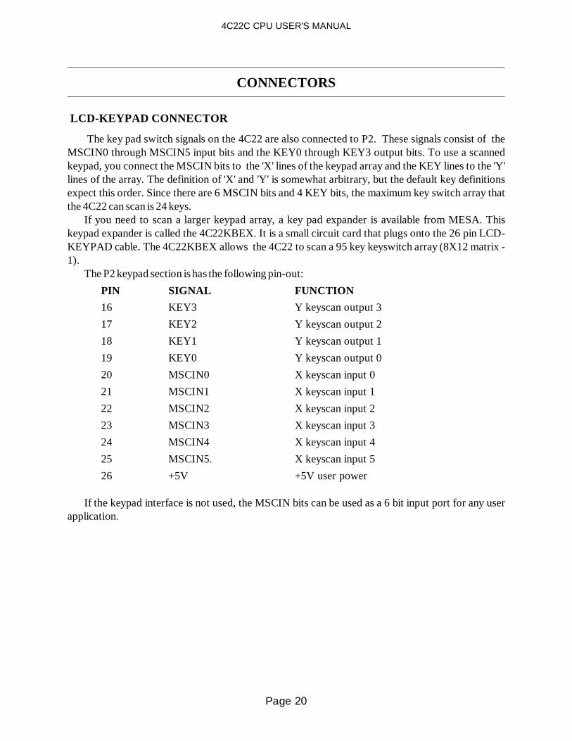
The key pad switch signals on the 4C22 are also connected to P2. These signals consist of theMSCIN0 through MSCIN5 input bits and the KEY0 through KEY3 output bits. To use a scannedkeypad, you connect the MSCIN bits to the 'X' lines of the keypad array and the KEY lines to the 'Y'lines of the array. The definition of 'X' and 'Y' is somewhat arbitrary, but the default key definitionsexpect this order. Since there are 6 MSCIN bits and 4 KEY bits, the maximum key switch array thatthe 4C22 can scan is 24 keys.
If you need to scan a larger keypad array, a key pad expander is available from MESA. Thiskeypad expander is called the 4C22KBEX. It is a small circuit card that plugs onto the 26 pin LCD-KEYPAD cable. The 4C22KBEX allows the 4C22 to scan a 95 key keyswitch array (8X12 matrix -1).
The P2 keypad section is has the following pin-out:
PIN SIGNAL FUNCTION
16 KEY3 Y keyscan output 3
17 KEY2 Y keyscan output 2
18 KEY1 Y keyscan output 1
19 KEY0 Y keyscan output 0
20 MSCIN0 X keyscan input 0
21 MSCIN1 X keyscan input 1
22 MSCIN2 X keyscan input 2
23 MSCIN3 X keyscan input 3
24 MSCIN4 X keyscan input 4
25 MSCIN5. X keyscan input 5
26 +5V +5V user power
If the keypad interface is not used, the MSCIN bits can be used as a 6 bit input port for any userapplication.
Page 20
4C22C CPU USER'S MANUAL

INSTALLATION
GENERAL
When the 4C22 has been properly configured for its application, it can be inserted into a PC/104stack. The standoffs should then be tightened to secure the 4C22 in its place. When the 4C22 issecured in the stack the I/O connectors headers can be plugged in from the sides.
I/O CONNECTOR ORIENTATIONThe serial port and keyboard connector on the 4C22 are 10 pin, right angle .1" headers. The
keyboard connector has pin 3 missing to prevent plugging the keyboard adapter cable on the serialport connector. Pin 10 of the serial port connector can be cut, and a keying plug installed in the cablemount header if desired. This will prevent plugging the serial cable on the keyboard port connector.
All connectors on the 4C22 have their pin one ends marked with a white square on the circuitcard. This corresponds with the red stripe on typical flat cable assemblies. If more positivepolarization is desired on the 10 pin headers, center polarized IDC header connectors should be used.These connectors will not fully mate with the pins on the 4I24M if installed backwards. A suggestedcenter polarized 10 pin IDC header is AMP PN 499934-1.
P2 on the 4C22 is a 26 pin right angle 2 mm header. If not used, the 5V output pin (pin 26) can becut. If this is done, a key may be installed in the pin 26 location of the IDC cable mount receptacle toprevent reverse installation.
Page 21
4C22C CPU USER'S MANUAL

CPU OPERATION
POWER CONSUMPTION The 4C22 is an all CMOS CPU, so overall power consumption of the 9 MHz CPU is typically less
than 1 watt (about 200 mA) running and about 140 mA halted. The -L version of the 4C22 uses lowerpower PALs for lower power consumption. The -L version typically draws approximately 110 mAwhen running and 50 mA when halted. If the absolute lowest power consumption is required, the CPUcan be halted when not active. It is the responsibility of the application program to execute the haltinstruction when idle.
HARDWARE TIC CLOCK
To simplify application timing tasks, and allow responsive keypad scanning, the hardware ticclock on the 4C22 runs at 100 CPS instead of the normal 18 CPS. This should have no serious sideeffects with well behaved programs, as the user tic clock still runs at 18 CPS. The 100 CPS to 18 CPSconversion is done with a rate multiplier type algorithm that does not detract from the long termaccuracy of the system tic clock.
Application programs that intercept the user tic interrupt (INT 1C ) will be still be interrupted atan average rate of 18 cps, but instead of the interrupts occurring regularly, the will occur at either 50or 60 mS intervals. If an application program requires interrupts with a constant interval , it shoulduse the hardware tic interrupt instead of the software tic.
WATCHDOG TIMER
The 4C22 is intended mainly for embedded system applications where there is no one to hit thereset switch should something go awry. To prevent a crashed or otherwise hung system fromremaining so indefinitely, the 4C22 is provided with a built in watchdog timer that will reset the 4C22if not 'fed' regularly. The time-out period of this counter is about 1 second on 9 MHz CPUs and about.6 seconds on 14.7 MHz CPUs. The default INT 1C (user tic clock) task 'feeds' the watchdog. Usersoftware must be careful not to disable interrupts for more than the timeout period or the watchdogmay bite! Any program that intercepts INT 1C must either chain through the old vector, or beresponsible for 'feeding' the watchdog itself.
SERIAL PORT The serial port on the 4C22 uses the V40's built in 8251 compatible serial port hardware. The
4C22 BIOS has some Int 1A functions that support the V40 serial port, including baud rate setting.The V40SER.PAS file in the source directory of the distribution disk has some example V40 serial
port interface routines. Since the V40's serial port is not 8250 (COMX) compatible, applicationprograms that directly access the serial port will not work with the 4C22 serial port.
Page 22
4C22C CPU USER'S MANUAL

CPU OPERATION
COM2/4 EMULATION
To support applications that require a COMx type port, the 4C22 has the ability to emulate COM2(Rev A PC cards) or COM4 (Rev B or later PC cards) .
If COM2/4 emulation is enabled, any access to the COM2 or COM4 port locations trigger a NMI.BIOS code then determines the type of access, port location, and output data if a write access wasattempted. The BIOS code then either supplies the appropriate data in the case of a read, does therequested operation to the V40 serial port in the case of a write.
The result of all this is that for almost all purposes, the emulated port appears to the system to bean actual 8250 type serial port. The emulated serial port has some limitations. The main limitation isspeed. The emulated port is not capable of communication at baud rates higher than about 9600 baud.The emulated port does not support interrupt driven operation.
Since the 4C22 serial port has only one handshake in and one handshake out line, the emulatedport must make do with these. Emulated 8250 modem status bits for DCD and CTS will always be intheir active states. The emulated DSR bit will follow the 4C22's serial port DSR input. Similarly, theRTS output on the 4C22 will follow the RTS register bit of the emulated 8250. The emulated RI bit(Ring indicator) will always be in the inactive state.
RS-232 / RS-485 OPERATION
The serial port on the 4C22 (Rev C and >) can use either RS-232 levels or RS-485 levels. To useRS-232 levels, the RS-485 transmit enable bit must be set high. This is because the RS-485 and RS-232 receiver share the same serial input pin on the V40 processor. When the RS-485 transmit enablebit is on, the RS-485 receiver is disabled, allowing the RS-232 signal to reach the V40.
The RS-485 driver enable bit is accessed by I/O writes to bit 0 of location 50H. All other bits at50H are don't-care.
RS-485 communication on the 4C22 is always half-duplex, because of the fact that the receiver isdisabled when the transmitter is enabled and vice-versa. When RS-485 is used with asynchronousserial ports, it is important that the idle (non-driven) line voltages be held in the marking state. Thiscan be done by providing a 1K pull-up resistor (to +5V) on the RS-485A line and a 1K pull downresistor (to ground) on the RS-485B line somewhere on the RS-485 bus. The RS-232 RXD lineshould be grounded when using RS-485 I/O, otherwise, the UART will see a line break whenever theRS-485 transmitter is enabled.
When using RS-485, it is the responsibility of the character or packet output routine to enable anddisable the RS-485 transmitter.
The Pascal include file in the source directory of the distribution disk has some low level serial portand RS-485 enable-disable procedures that can be used as examples for writing your own code.
Page 23
4C22C CPU USER'S MANUAL
CPU OPERATION
SERIAL FILE DOWNLOAD
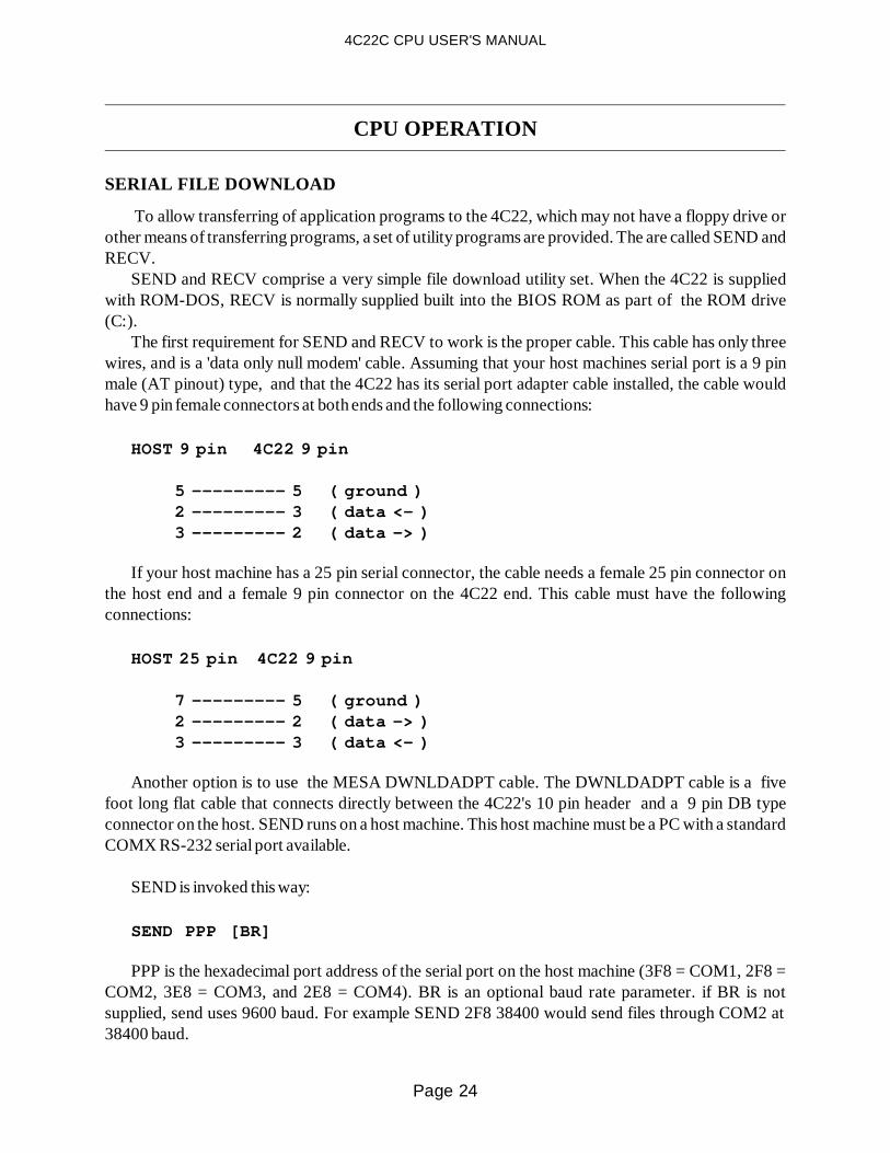
To allow transferring of application programs to the 4C22, which may not have a floppy drive orother means of transferring programs, a set of utility programs are provided. The are called SEND andRECV.
SEND and RECV comprise a very simple file download utility set. When the 4C22 is suppliedwith ROM-DOS, RECV is normally supplied built into the BIOS ROM as part of the ROM drive(C:).
The first requirement for SEND and RECV to work is the proper cable. This cable has only threewires, and is a 'data only null modem' cable. Assuming that your host machines serial port is a 9 pinmale (AT pinout) type, and that the 4C22 has its serial port adapter cable installed, the cable wouldhave 9 pin female connectors at both ends and the following connections:
HOST 9 pin 4C22 9 pin
5 --------- 5 ( ground ) 2 --------- 3 ( data <- ) 3 --------- 2 ( data -> )
If your host machine has a 25 pin serial connector, the cable needs a female 25 pin connector onthe host end and a female 9 pin connector on the 4C22 end. This cable must have the followingconnections:
HOST 25 pin 4C22 9 pin
7 --------- 5 ( ground ) 2 --------- 2 ( data -> ) 3 --------- 3 ( data <- )
Another option is to use the MESA DWNLDADPT cable. The DWNLDADPT cable is a fivefoot long flat cable that connects directly between the 4C22's 10 pin header and a 9 pin DB typeconnector on the host. SEND runs on a host machine. This host machine must be a PC with a standardCOMX RS-232 serial port available.
SEND is invoked this way:
SEND PPP [BR]
PPP is the hexadecimal port address of the serial port on the host machine (3F8 = COM1, 2F8 =COM2, 3E8 = COM3, and 2E8 = COM4). BR is an optional baud rate parameter. if BR is notsupplied, send uses 9600 baud. For example SEND 2F8 38400 would send files through COM2 at38400 baud.
Page 24
4C22C CPU USER'S MANUAL

CPU OPERATION
SERIAL FILE DOWNLOAD
Once SEND is running on the host machine, RECV is run on the client CPU card to downloadfiles. Note that RECV only works on MESA V40 based CPU's!
RECV is invoked this way:
RECV RFN LFN [BR] [Q]
RFN is the remote file name (the source file) which is relative to the path where send waslaunched. LFN is the local file name (the target file).The Q parameter causes SEND to be abortedwhen the file transfer is complete. BR is an optional baud rate parameter. If BR is not supplied, RECVuses 9600 baud. For example:
RECV FOO GOO 38400 Q
Would get the remote file FOO, write it to the local file GOO, and abort SEND when done. Alldata transfers would be done at 38400 baud.
If you set the baud rates on the command line, the SEND baud rate must match the RECV baudrate. Maximum practical baud rate is 57600 baud. You may not be able to use the maximum baud rate,depending on your host CPU speed, serial port characteristics, interconnect cable etc. (Your mileagemay vary)
The optional tool chip supplied with ROM-DOS versions of the 4C22 has a batch file R.BAT thatsimplifies receiving files. R.BAT assumes that send was invoked with 38400 as the baud rate. To useR.BAT you type:
R FILENAME
R.BAT consists of one line: D:RECV %1 %1 38400
Page 25
4C22C CPU USER'S MANUAL

CPU OPERATION
CONSOLE SWITCHINGThe 4C22 can use an XT keyboard, the scanned keypad or the serial port for console input.
Console out can be directed to a video card, the LCD module or the serial port. To determine whichconsole option is used, the 4C22 supports extended INT 1A functions that allow dynamic switchingof console input and output. Console output defaults to a video card if a video card is detected in thesystem. If a video card is detected, the console input comes from the XT keyboard port. If no videocard is detected in the system, and the LCD display is not enabled in the EEPROM setup, consoleinput and output default to the serial port. If the LCD option is enabled in the EEPROM setup, thedefault console in comes from the XT keyboard port.
The default EEPROM setup for 4C22's has the LCD disabled, so in absence of a video card in thesystem, the serial port will be used as the system console. The default setup has the serial port baudrate set to 9600 baud.
The 4C22 distribution disk has some batch files in the DEMO directory that dynamically reroutethe console in and out. Consult the BATREAD.ME file in that directory for more information onthose files.
The key pad console in option must be explicitly enabled by calling the appropriate extended INT1A function. There are some restrictions about combinations of input devices. The serial port and theXT keyboard port use the same interrupt (IRQ 1), so they can not be enabled simultaneously. Thekeypad scanning logic shares input bits with the XT keyboard port, so the keypad can not be used atthe same time the XT keyboard is enabled. The XT keyboard should be disconnected from the 4C22before the keypad is enabled, or the BIOS will receive what it thinks is a continuous stream of keypadcharacters.
Page 26
4C22C CPU USER'S MANUAL

CPU OPERATION
EXTENDED INT 1A FUNCTIONS Console I/O redirection, and some other miscellaneous control functions on the 4C22 are
accessed via extended INT 1A calls. The calling convention used in all these calls is as follows:register AH = 87H, register BX is the offset part of the structure pointer, and register CX is thesegment part of the structure pointer. CX:BX points to a structure, the first byte of which is thefunction number, and the second byte is the returned status byte. After these first bytes, a variablenumber of byte or word parameters follow.
For a full description of the INT 1A extended functions, you should refer to the INT 1A.H (for Cusers), and INT1A.INC (for assembly programmers) files in the source directory of the 4C22distribution disk. The following is a brief list of extended INT 1A functions for quick reference:Subfunctions are indented and listed under main functions.
F_SYSCNTRLINFOQ = 0Get system control code revision level, etc.
F_SYSKBSOURCEQ = 1 Inquire about keyboard source.
F_SYSKBREROUTE = 2Select keyboard source.
KBSRC_KEYBOARD = 0 Take input from PC keyboard. KBSRC_SERIAL = 1 Take input from local serial channel. KBSRC_OFF = 2Turn off serial and PC keyboard input.
Page 27
4C22C CPU USER'S MANUAL

CPU OPERATION
EXTENDED INT 1A FUNCTIONS
F_SYSVIDEOSOURCEQ = 3 Inquire about video destination.
F_SYSVIDEOREROUTE = 4Select video destination.
VIDDEST_VIDEO = 0 Send video output to standard video. VIDDEST_SERIAL = 1 Send video output to local serial channel. VIDDEST_LCD = 2 Send video output to local LCD display. VIDDEST_STUB = 3Send video output to black hole.
F_SYSSCUBAUDSEL = 5 Set V40 SCU baud rate.
BAUDSEL_110 = 0 BAUDSEL_150 = 1 BAUDSEL_300 = 2 BAUDSEL_600 = 3 BAUDSEL_1200 = 4 BAUDSEL_1800 = 5 BAUDSEL_2000 = 6 BAUDSEL_2400 = 7 BAUDSEL_3600 = 8 BAUDSEL_4800 = 9 BAUDSEL_7200 = 10 BAUDSEL_9600 = 11 BAUDSEL_19200 = 12 BAUDSEL_38400 = 13 BAUDSEL_57600 = 14 BAUDSEL_115200 = 15 The various baud rate selection constants.
Page 28
4C22C CPU USER'S MANUAL

CPU OPERATION
SETUP STORAGE
Many 4C22 options can be saved in the serial EEPROM on the 4C22 card. These options include:initial baud rate, LCD parameters, contrast setting, etc. These parameters can be set with the INT 1Afunctions or the provided utility SET4C22.EXE
SET4C22 reads a text file of setup options, and programs these into the 4C22's EEPROM. Thesesetup files have a default extension of .CF. SET4C22 and a number of configuration files are located inthe UTILS directory of the 4C22 distribution floppy. SET4C22 is invoked with the configuration filename as a parameter: For example:
SET4C22 4C22.CF
Would configure the 4C22 with the EEPROM settings in the 4C22.CF configuration file. SET4C22 has three command line switches: /D, /N and /Q. These command line switches follow
the file name. The /D option causes the 4C22 EEPROM to be initialized to it's default configuration.When the /D option is used, no file name is needed. The /N option causes the configuration file tomodify the default configuration, and store the result into the EEPROM. If /Not specified, all optionsnot specifically changed in the configuration file will remain at their previous settings.
As long as the /N or /D switches are not used, configuration files loaded with SET4C22 only affectthe options specified in the file. This makes it possible to separate the configuration files into piecesthat only affect a certain aspect of 4C22 operation. A good example of this is LCD configuration. Thespecific display parameters for a LCD panel can be included in a LCD only configuration file that isloaded to make the 4C22 drive that panel. Loading this LCD only file would not change any of theother 4C22 setup parameters. An example LCD setup file, located in the UTILS directory of the 4C22distribution diskette is SAMUG13.CF. This is a configuration file for the Samtron UG13 64X128display.
LCD configuration files differ depending on 4C22 model. Revision C and later 4C22's use LCDconfiguration files with the extension .CCF instead of .CF . Using the wrong revision LCDconfiguration file will result in improper displa y operation.
Note that EEPROM settings do not take effect until the 4C22 is reset.
Page 29
4C22C CPU USER'S MANUAL

DISK EMULATOR OPERATION
GENERAL
The 4C22 has a built in nonvolatile disk emulator with a capacity of up to 2M bytes using EPROMor 1 M byte using battery backed RAM or FLASH EEPROM.
Two 32 pin sockets on the 4C22 can be used for disk emulator memory chips. These two chips canbe used together as a single drive or each chip can be configured as an independent drive. When twodrives are configured, the chips can be of different types. For example, a configuration with flashEEPROM for program storage and battery backed RAM for data logging is a popular arrangement.
When using the built in disk emulator, the disk type configuration jumpers must be first set tomatch the type of disk emulator chip(s) used. (See the HARDWARE CONFIGURATION section ofthis manual.)
The 4C22 disk emulator is viewed hard disk by system software. This means that the firstemulated drive will be drive C: , and the next emulated drive will be drive D.
RELIABILITY In an embedded system environment where a system that won't boot is basically a failed system, it
is important to understand some characteristics of the DOS operating system that applies to diskaccess. When DOS writes a file, it writes to the FAT and directory areas of the drive (emulated orreal).
If there is any chance that a system can be reset or power can fail when writing to this disk, allinformation on the disk could become inaccessible, not just the file that was being written.
The reason is that when DOS writes a directory entry it always writes a full sector, not just thedirectory or FAT entry required. If the sector write is not completed, the sector with the directory orFAT entry that was being written will have an invalid CRC. This can affect any file on the drive!
In applications that do frequent disk writes, there are two possible solutions to this problem. Thefirst solution is to disable emulated disk CRC checking. This will make a partially re-written sectorreadable by the operating system. This will only improve the odds of surviving a power off or resetduring a file write, not totally eliminate the problem. Turning off CRC's will also mask possiblehardware problems, so is not generally suggested. The second solution is to configure a two drivesystem, with a drive (usually C:) used as the software drive, and the other drive (usually D:) used asthe data drive. Any files writes during normal operation would be done to the D: drive. If any problemoccurs on the D: drive, software on the C: drive can attempt to recover the data, and then re-initializethe D: drive.
As a further precaution the data drive can be split into two logical drives with FDISK. If the datadrive was physical drive D, the two logical drives would be drive D: and drive E:. When this is done,data corruption on one logical drive will not effect the other drive, allowing a dual write scheme to beused to protect valuable data.
Page 30
4C22C CPU USER'S MANUAL

DISK EMULATOR OPERATION
DISK EMULATOR INITIALIZATION
Before using the disk emulator, it needs to be initialized so that the 4C22 BIOS knows the size,chip type, and organization of the disk emulator.
This initialization is done with INITRAMD.EXE. INITRAMD.EXE is supplied in the DISKsubdirectory of the 4C22 distribution disk. If INITRAMD is run with a /L parameter, it will list thetypes of disk emulator chips supported by the 4C22 BIOS. Each type of disk emulator chip has acorresponding Devicetype number.
To initialize a disk emulator, you invoke INITRAMD as follows:
INITRAMD /CStartChip /NNumberOfChips /DDeviceType [/F [O | D]]
Where StartChip is 0 or 1, NumberOfChips is 1 and DeviceType is a number listed by theINITRAMD /L command.
The /F parameter invokes a built-in FDISK and FORMAT option. The /F option can be followedby a D or O. The D or O specifies whether a DOS format (D) or ROM-DOS format (O) is used.
.The ROM-DOS format is specially optimized for small drives, and wastes a minimum of diskspace. The DOS format wastes more space, but is compatible with most version of MS-DOS. Do notuse the ROMDOS format with DOS or unpredictable file system behavior will result!
On the 4C22, there are 2 available sockets, the upper socket (U11) and the lower socket (U17).INITRAMD numbers these sockets such that the lower socket is socket 0 and the upper socket issocket 1.
If you wanted to initialize a 2 socket disk emulator using device type 1, the INITRAMD commandwould be:
INITRAMD /C0 /N2 /D1 /FD( Initialize a disk emulator starting at socket 0, using 2 sockets and device type 1 - DOS format )
It is also possible to initialize two independent disk emulators by invoking INITRAMD twice,once per socket:
INITRAMD /C0 /N1 /D3 /FO( Initialize disk starting at socket 0, using 1 socket and device type 3 - ROMDOS format ) INITRAMD /C1 /N1 /D5 /FO( Initialize disk starting at socket 1, using 1 socket and device type 5 - ROMDOS format )
Once the disk emulator has been initialized, the 4C22 needs to be reset before the new disk will berecognized by the operating system.
Unlike previous MESA disk emulator software, you should not normally need to run FDISK orFORMAT as long as you specify the /F parameter when initializing a drive.
Page 31
4C22C CPU USER'S MANUAL

LCD OPERATION
GENERAL
The 4C22 is capable of driving many types of small graphic LCD panels. Panel sizes of 128 by 64pixels to 480 by 128 pixels can be driven by the 4C22.
The 4C22 LCD panel interface drives graphic panels with four data bits, and four timing signals. Apartial list of compatible panel types is listed below, but the 4C22 will drive many small graphic panelswith 4 data bits and the following control signals:
CL2 or CP Shift clock
CL1 Latch signal
FLM Frame signal
M AC drive signal
Panels the 4C22 can drive are sometimes referred to as single panel single drive type.
SYSTEM RESOURCES NEEDEDThe 4C22 uses DMA channel 1 (DRQ1 and DACK1) and IRQ 5 when driving the LCD panel.
Make sure that you do not drive IRQ5 or DRQ1 when using the LCD panel or the display willmalfunction.
System memory needs to be allocated for the display panel refresh buffer. This memory isallocated by the BIOS at system startup if the LCD is enabled.
The size of this buffer depends on the display size and the number of planes used. The current LCDvideo BIOS supports one or two planes. Typical memory usage is about 2.5K per plane for a 128X64display up to about 20K bytes per plane on a 320X240 display.
TEXT MODEWhen small LCDs are used with the 4C22, the display is not hardware compatible with the
standard monochrome or color IBM type displays.When small LCD's are used, there are no equivalents to the video modes used on a normal PC.
Changing video mode (INT 10 function 00) will only clear the screen. The display is always in agraphics mode.
The 4C22 BIOS does however, support most of the INT 10 video display calls, so most softwarethat accesses the display through the BIOS will work. (within the limits of the smaller display size).
Page 32
4C22C CPU USER'S MANUAL

LCD OPERATION
TEXT MODE
The 4C22 BIOS does not maintain a copy of the characters and attributes in the current display.This means that INT 10 functions that depend on the previous display contents will not work. INT 10functions that may cause trouble are function 08h (read character and attribute) and function 0Ah(write character at cursor). Function 0Ah may cause trouble because it assumes that the characterattribute to use is the one at the current character position in video memory. The 4C22's BIO's'function 0Ah simply writes characters with the default attributes.
MESA is working on a ANSI.SYS replacement that is compatible with the small LCD displayenvironment for those text and remote terminal applications that need ANSI compatibility
Most compilers have an option to use the BIOS instead of direct memory access when writing tothe display. You will need to enable this option when compiling applications using the LCD display.
TEXT FONTS
The standard 4C22 BIOS has two available fonts for text display, a large and a small font. Thesmall font is suggested for most applications. This font uses a 5X7 sized character in a 6X8 cell. Thelarge font is useful where the display must be visible from a distance. The large font uses 7X9characters in a 8X14 cell. The font type is chosen via an extended INT 10 function. See the sectionEXTENDED INT 10 FUNCTIONS for more information.
TEXT SCREEN SIZESThe following table shows the maximum number of character rows and columns for various size
LCD panels:
PANEL WIDTH COLS (small font) COLS (large font)
128 21 16
240 40 30
256 42 32
320 53 40
480 80 60
640 106 80
Page 33
4C22C CPU USER'S MANUAL

LCD OPERATION
TEXT SCREEN SIZES
PANEL HEIGHT ROWS (small font) ROWS (large font)
64 8 4
128 16 9
240 30 15
TEXT ATTRIBUTES The 4C22 BIOS supports blink and reversed video attributes. These character attributes are
selected with the standard INT 10 functions. Underline and intensity attributes are ignored.
TEXT WINDOWWhen the small LCD panel is used, text output can be confined to a user defined rectangular
region within the borders of the display. All standard text operations will be confined to this region,including scrolling, screen clearing, and characters that wrap at the end of the line.
The purpose of this text window allow graphic areas around the periphery of the display forlabeling softkeys, status indicators etc. The text window function can also be used with the regionsave and restore functions to pop-up notifiers on a graphics screen, and then restore the screen whenthe notifier is dismissed.
The text window dimensions are defined with an extended INT 10 function. Window dimensionsare specified in pixels. See the EXTENDED INT 10 FUNCTIONS section for more information.
The text window is set to the physical display limits when the BIOS initializes the LCD panel. Textwindows should normally be set so that the window height is a multiple of the current font height. Ifthis is not done, scrolling may leave partial characters visible on the display.
Page 34
4C22C CPU USER'S MANUAL

LCD OPERATION
GRAPHICS
The 4C22 BIOS has support for several graphics operations. These operations include BitBLT,single pixel width line drawing (Bresenham algorithm), screen region save and restore, and individualdot drawing.
If 2 planes are used, blinking graphic objects are supported. These are useful for calling attentionto specific screen areas. Blinking graphic objects do not have any system performance overhead, asthey are implemented by dynamically switching the display buffers. Using 2 planes will reducedrawing speed slightly, and doubles the size of the frame buffer. This may be a consideration whenusing the larger displays.
EXTENDED INT 10 FUNCTIONSThe LCD specific video control functions via extended INT 10 calls. The calling convention used
in all these calls is as follows: register AH = 80H (control functions) or 81H (graphic functions),register BX is the offset part of the structure pointer, and register CX is the segment part of thestructure pointer. CX:BX points to a structure, the first byte of which is the function number, and thesecond byte is the returned status byte. After these first bytes, a variable number of byte or wordparameters follow.
For a full description of the INT 10 extended functions, you should refer to the INT10.H (for Cusers), and INT10.INC (for assembly programmers) files in the source directory of the 4C22distribution disk. Some example programs that use the extended INT 10 functions are provided in thesource directory
The following is a brief listing of the extended INT 10 functions:
CONTROL FUNCTIONS (AH= 80H)
F_DISPCNTRLINFOQ = 0Get display control code revision level
F_DISPCHECKSETUP = 1Validate setup parameters.
F_DISPINIT = 3Activate the LCD display.
F_DISPMODEGET = 4Get display operating modes information.
Page 35
4C22C CPU USER'S MANUAL

LCD OPERATION
EXTENDED INT 10 FUNCTIONS
CONTROL FUNCTIONS (AH= 80H)
F_DISPMODESET = 5 Set display operating mode.
F_DISPGETBUFPTR = 10 Get segment of display buffer.
F_DISPSETBUFPTR = 11 Set segment of display buffer.
F_DISPSTATEGET = 12 Get display on/off state information.
F_DISPSTATESET = 13 Set display on/off state.
F_DISPBKLTSTATEGET = 14 Get display backlight on/off state.
F_DISPBKLTSTATESET = 15Set display backlight on/off state.
F_DISPCONTRASTGET = 16 Get current display contrast setting.
F_DISPCONTRASTSET = 17 Set display contrast.
Page 36
4C22C CPU USER'S MANUAL

LCD OPERATION
EXTENDED INT 10 FUNCTIONS
GRAPHIC FUNCTIONS (AH= 81H)
F_GRFXDISPINFOQ = 0 Get graphics code revision level
F_GRFXDISPDIMQ = 1 Get display dimensions.
F_GRFXTTYINFOGET = 2 Get TTY region information.
F_GRFXTTYINFOSET = 3 Set TTY region information.
F_GRFXCRSRXABLQ = 4 Get cursor xable state information.
F_GRFXCRSRXABL = 5 Xable cursor display.
F_GRFXTTYPATGET = 6 Get TTY region fill pattern.
F_GRFXTTYPATSET = 7 Set TTY region fill pattern.
F_GRFXPATGET = 8 Get non-TTY region fill pattern.
F_GRFXPATSET = 9 Set non-TTY region fill pattern.
Page 37
4C22C CPU USER'S MANUAL

LCD OPERATION
EXTENDED INT 10 FUNCTIONS
GRAPHIC FUNCTIONS (AH= 81H)
F_GRFXERASEREGN = 10 Erase a rectangular region.
F_GRFXDRAWDOT = 11 Draw a dot.
F_GRFXDRAWLINE = 12 Draw a single-pixel line.
F_GRFXBITBLT = 13 BitBLT to a rectangular screen region.
F_GRFXUNBITBLT = 14BitBLT from rectangular screen region.
F_GRFXERASETTY = 15 Erase the TTY region.
F_GRFXERASENONTTY = 16 Erase the non-TTY region.
F_GRFXSETTTYDIM = 17 Set TTY region location/dimensions by point and size.
F_GRFXFONTINFOGET = 18 Get information about ROMBIOS-resident TTY fonts.
F_GRFXATTACHFONT = 19 Specify the font for the TTY font.
Page 38
4C22C CPU USER'S MANUAL

LCD OPERATION
EXTENDED INT 10 FUNCTIONS
GRAPHIC FUNCTIONS (AH= 81H)
F_GRFXSETTTYLOC = 21 Set TTY region location/dimensions by rectangular region.
F_GRFXSELFONT = 20 Select TTY font by number.
F_GRFXTFONTINFOGET = 22 Get information about the current TTY font.
F_GRFXNTFONTINFOGET = 23 Get information about the current non-TTY font.
F_GRFXATTACHNTFONT = 24 Specify the font for the non-TTY font.
F_GRFXDRAWCHAR = 25 Draw a character from the non-TTY font at the specified pixel coordinate.
F_GRFXSAVEREGNSIZEQ = 26 Get size of buffer required by the specified LCD display region image.
F_GRFXSAVEREGN = 27 Save specified LCD display region to image buffer.
F_GRFXUNSAVEREGN = 28 Restore specified LCD display region from image buffer.
Page 39
4C22C CPU USER'S MANUAL

LCD OPERATION
LCD TYPES
The 4C22 BIOS needs to programmed with appropriate values of panel parameters before theLCD panel is enabled. These parameters include the panel dimensions, and the nominal VEE supplyvoltage. The BIOS LCD support parameters can be dynamically initialized with an extended INT 10function, but normally the LCD parameters are written to the 4C22 setup EEPROM with SET4C22.A number of LCD configuration files are provided in the 4C22 distribution diskette in the UTILSdirectory. These files have the LCD dimension specific information plus the VEE setting forapproximately the right LCD contrast.
A number of adapters for specific displays are available from MESA. These adapters eliminate theneed to hand wire the LCD cable. Schematics for some of these adapters are included in the schematicsection of the manual.
Some panels have a separate VEE and contrast voltage input. These panels need an externalpotentiometer to adjust the contrast.
The following are representative LCD panel types that can be driven by the 4C22:
DENSITRON PANEL X Dis. Y Dis. X Tot. VEE NOTES
LMG6627 240 128 240 -23 CFL backlight Pot. contrast adjust Requires 4C22 HV opt.
OPTREX PANEL X Dis. Y Dis. X Tot. VEE NOTES
DMF660 240 128 240 -20 EL backlight optionPot. contrast adjust
DMF690 640 64 640 -8.6 EL backlight optionSoftware contrast adj.
Page 40
4C22C CPU USER'S MANUAL

ee
LCD TYPES
SAMTRON PANEL X Dis. Y Dis. X Tot. VEE NOTESUG-13B-02 128 64 160 -8.2 EL backlight option
Software contrast adj.
UG-24D-01 240 128 240 -19 EL backlight option Pot. contrast adjust( Note: strange 0-5V contrast range)
UG-24D-02 240 128 240 -15.8 Software contrast adj.UG-25D-02 256 128 320 -13.8 EL backlight option
Software contrast adj.
UG-32F-01 320 240 240 -19 Ref./EL backlightSoftware contrast adjust4C22F (14.7 MHz CPU) only
UG-32F-02 320 240 240 -19 Ref./EL backlightSoftware contrast adjust4C22F (14.7 MHz CPU) only
UG-32F-03 320 240 240 -19 CCFL backlightSoftware contrast adjust4C22F (14.7 MHz CPU) only
UG-48D-02 480 128 480 -12.4 EL backlight option Software contrast adj.
Page 41
4C22C CPU USER'S MANUAL

LCD OPERATION
LCD TYPES
SANYO
PANEL X Dis. Y Dis. X Tot. VEE NOTES LCM-5627-02NAK 240 128 240 -23V CFL backlight
Pot. contrast adjustRequires 4C22 HV opt.
LCM-5627-22NAK 240 128 240 -23V CFL backlight
Pot. contrast adjustRequires 4C22 HV opt.
Both of the above Sanyo displays are similar to Densitron LMG6627
SEIKO
PANEL X Dis. Y Dis. X Tot. VEE NOTES G191C 192 128 240 -12.4 EL backlight option
Software contrast adj.
STANLEY
PANEL X Dis. Y Dis. X Tot. VEE NOTES GMF25064ABTW 256 64 256 -12 CCFL backlight
Touch switch availablePot contrast adjust.
GMF250128FBTW 256 64 256 -20 CCFL backlightTouch switch availablePot contrast adjust.
GMF32024ABTW 256 64 256 -23 CCFL backlightPot contrast adjust.Requires 4C22 HV option4C22F (14.7 MHz CPU) only
Page 42
4C22C CPU USER'S MANUAL

LCD OPERATION
LCD POWER SUPPLY
The 4C22 provides a programmable negative power supply for LCD VEE generation. Thenormal range of the power supply is 0 to -20 volts.
For the few displays that require more than -20V VEE, the 4C22 has an optional higher voltageoutput power supply. Please contact MESA if you need the higher voltage power supply.
The VEE voltage output is programmable with 10 bit resolution. The power supply output islinked to the 4C22's VCC in such a way that the difference between VCC and VEE remains constantat a given VEE setting. This is done because LCD panel contrast depends on the difference betweenVEE and VCC, not VEE alone. By maintaining a constant VEE-VCC, display contrast is much lessaffected by VCC variations.
Setting the LCD VEE voltage is done as part of the LCD panel initialization process. The LCDVEE will be determined by the setup values specified in a configuration file and written to theEEPROM with SET4C22. The VEE voltage can also be changed dynamically by calling theF_DISPCONTRASTSET function. This function uses a single word parameter (DISPCONT) to setthe VEE voltage. The equation for the VEE voltage is -((DISPCONT/65535) * 25 -VCC). Theequation for DISPCONT in VEE is (-VEE+VCC)/25*65535. For example, to set the VEE voltage to-10V , assuming VCC is 5V, DISPCONT would be set for (10+5)/25 * 65535 or 39321. It is always agood idea to check the LCD signals and power supply voltages before connecting a LCD panel to the4C22.
DEMO PROGRAMSA number of demonstration programs for the LCD display are included on the 4C22 distribution
disk. LITBLT.EXE is a demonstration program designed for a 128X64 (Samtron UG13B- 02 for
example) display, and the MESA membrane switch array for that display. LITBLT demonstratesTTY windows, bitBLT, line drawing, logical operations to screen memory, and blinking graphics.LITBLT.EXE depends on the 4C22 EEPROM setup being initialized for the 128X64 display with 2planes (The default 4C22 setup).
BIGBLT.EXE is a similar demonstration program designed for 240X128 or larger displays.BIGBLT.EXE requires only one plane and uses the XT keyboard. BIGBLT.EXE depends on the4C22 EEPROM setup being initialized for the display being used.
SC.EXE is a demonstration program that allows you to set and permanently save the displaycontrast setting on the 128X64 display. SC.EXE depends on the 4C22 EEPROM setup beinginitialized for the 128X64 display, and the MESA membrane switch array for that display.
SCBIG.EXE is a similar program for larger displays. SCBIG.EXE requires a display 128X128 orlarger, and uses the XT keyboard cursor keys to adjust and save the contrast setting.
Page 43
4C22C CPU USER'S MANUAL

LCD OPERATION
MINT
MINT.EXE is a simple program for calling MESA's extended interrupt functions from thecommand line. MINT allows fairly complex demonstrations of the extended interrupt functions to beexecuted from batch files. MINT is invoked with a series of parameters on the command line. Thecommand- parameter sequence is:
MINT IN AH FN EC SF PAR0 PAR1 PAR2...
Where the first five parameters are always 2 digit hexadecimal values as follows: IN is theinterrupt number, AH is the register AH value, FN is the main function number, SF is the sub functiona number, and EC is the function status return variable.
MINT loads register AH with the AH value, loads CX:BX with a pointer to a structure consistingof the sequence FN,RV,SF,PAR0,PAR1,PAR2..., and then calls interrupt IN.
The PARX values that follow these can be byte or word hexadecimal parameters. MINT expectsword parameters to be 4 characters long and byte parameters to be 2 characters long. For example0010 is a word parameter and FF is a byte parameter.
MINT is best used in short batch files when testing 4C22 functions. For example the followingbatch file (VIDOUT.BAT) switches the video output stream to the video monitor.
@ECHO OFFMINT 1A 87 04 00 00 rem INT AH MAINFUNC ERRCODE STDVID rem route video out to standard video
The following batch file (SETCON.BAT) expects a 4 digit hexadecimal contrast value on thecommand line, and sets the contrast value (VEE voltage) to that value.
@ECHO OFFMINT 10 80 11 00 %1rem INT AH MAINFUNC ERRCODE CONTRAST VALUE rem LCD contrast value (VEE) must be 4 (hex) digits!
The DEMO directory of the distribution disk has a series of these batch files for demonstrationpurposes.
Page 44
4C22C CPU USER'S MANUAL

LCD OPERATION
PCX2HEX
PCX2HEX is a MESA supplied utility that makes it simpler to embed images into applicationprograms. PCX2HEX converts a monochrome PCX picture file to a hexadecimal ASCII array ofbytes suitable for inclusion in C or Pascal source code.
To make a picture for embedding in an application program, you first create the PCX file with oneof the many available 'Paint' type programs. Most of these paint programs allow you to specify theimage size when you create a new file. You need to specify this size to match the size of your desiredimage. You should make the picture width a multiple of 16 pixels wide for compatibility with PCXeditors. The PCX file must be a 1 plane (monochrome) file type.
Once you hav e created a suitable image file, you run PCX2HEX to convert the PCX file to a hexconstant. PCX2HEX can make files suitable for C or Pascal programs. To make a C type file fromGOOBER.PCX, you would type:
PCX2HEX GOOBER.PCX C
This would create a GOOBER.H file for inclusion in C source code. To make a Pascal type filefrom GOOBER.PCX, you would type:
PCX2HEX GOOBER.PCX PASCAL
This would create a GOOBER.PAS file for inclusion in Pascal source code The constant array willhave the same name as the PCX file that it was created from. In addition to the array of bytes that makeup the picture, two 16 bit constants are defined in the hex file. These are the X and Y dimensions of thepicture. These dimensions have the same name as the PCX file that they were created from except thatthe X dimension has XDIM appended to the name and the Y dimension has YDIM appended. Thesedimensions are needed by the BITBLT function.
After the desired hex constant file(s) have been created, they can be included in your applicationprogram source code. They can then be displayed on the LCD screen using the INT 10 BITBLTfunction. For an example of using the hex constant files with BITBLT, you can refer to the SC.PASfile in the SOURCE directory of the 4C22 distribution floppy.
Page 45
4C22C CPU USER'S MANUAL

KEYPAD OPERATION
GENERAL
The 4C22 has the capability of scanning a key matrix of up to 24 keys in a 4 by 6 array. This isdesigned to simplify embedded instrument and controller applications where a standard keyboard isinappropriate.
The keypad scanning is enabled via an INT 1A function. Running the batch file KEYPAD.BATgives a simple demonstration of keypad operation.
The XT keyboard needs to be disconnected from the 4C22 for proper operation of the membraneswitch
The current BIOS returns a fixed set of scan codes from the keypad array. Ultimately, these keyswill be programmable but will still start out with these values as the default set of keys. The defaultkey codes returned by the keypad array are as follows:
KEY3 KEY2 KEY1 KEY0
MSCIN0 F1 SHFT F1 ALT F1 CONT F1
MSCIN1 F2 SHFT F2 ALT F2 CONT F2
MSCIN2 F3 SHFT F3 ALT F3 CONT F3
MSCIN3 F4 SHFT F4 ALT F4 CONT F4
MSCIN4 F5 SHFT F5 ALT F5 CONT F5
MSCIN5 F6 SHFT F6 ALT F6 CONT F6
DISPKEYS DISPKEYS is a simple utility provided with the 4C22 for the purpose of displaying keyboard
scancodes and keynames. You exit DISPKEYS by pressing the same key 5 times in a row. DISPKEYS can be helpful when connecting a new keypad switch array to determine the proper
connections.
Page 46
4C22C CPU USER'S MANUAL

REFERENCE INFORMATION
SPECIFICATIONS
MIN MAX UNIT
POWER SUPPLY:Voltage 4.5 5.5 V Supply current (9.2 MHz -L) --- 130 mA (no ext. load)Supply current (9.2 MHz) --- 250 mA (no ext. load) Supply current (14.7 MHz) --- 320 mA (no ext. load)
LCD POWER SUPPLY: VEE Voltage -20 0 V VEE current (-5V to 15V) --- 10 mA VEE current (-15 to 20V) --- 7 mA VDD Voltage VCC-.5 VCC V VDD current --- 7 mA
BUS LOADING AND DRIVE:Input capacitance --- 15 pF Input leakage current --- 5 uA Output drive capability 100 --- pF Output sink current --- 6 mA
ENVIRONMENTAL: Operating temperature range -I version -40 +85 o C
-C version 0 +70 o C Relative humidity 0 90 Percent
Non-condensing
Page 47
4C22C CPU USER'S MANUAL

REFERENCE INFORMATION
WARRANTY
Mesa Electronics warrants the products it manufactures to be free effects in material andworkmanship under normal use and service for the period of 2 years from date of purchase. Thiswarranty shall not apply to products which have been subject to misuse, neglect, accident, orabnormal conditions of operation.
In the event of failure of a product covered by this warranty, Mesa Electronics, will repair anyproduct returned to Mesa Electronics within 2 years of original purchase, provided the warrantor'sexamination discloses to its satisfaction that the product was defective. The warrantor may at itsoption, replace the product in lieu of repair.
With regard to any product returned within 2 years of purchase, said repairs or replacement will bemade without charge. If the failure has been caused by misuse, neglect, accident, or abnormalconditions of operation, repairs will be billed at a nominal cost.
THE FOREGOING WARRANTY IS IN LIEU OF ALL OTHER WARRANTIES,EXPRESS OR IMPLIED. INCLUDING BUT NOT LIMITED TO ANY IMPLIEDWARRANTY OF MERCHANTABILITY, FITNESS, OR ADEQUACY FOR ANYPARTICULAR PURPOSE OR USE. MESA ELECTRONICS SHALL NOT BE LIABLE FORANY SPECIAL, INCIDENTAL, OR CONSEQUENTIAL DAMAGES, WHETHER INCONTRACT, TORT, OR OTHERWISE.
If any failure occurs, the following steps should be taken:
1. Notify Mesa Electronics, giving full details of the difficulty. On receipt of this information,service data, or shipping instructions will be forwarded to you.
2. On receipt of the shipping instructions, forward the product, in its original protectivepackaging, transportation prepaid to Mesa Electronics. Repairs will be made at Mesa Electronics andthe product returned transportation prepaid.
Page 48
4C22C CPU USER'S MANUAL

REFERENCE INFORMATION
SCHEMATICS
Page 49
4C22C CPU USER'S MANUAL

Page 50
4C22C CPU USER'S MANUAL

REFERENCE INFORMATION
MECHANICAL DRAWINGS
Page 51
4C22C CPU USER'S MANUAL

Page 52
4C22C CPU USER'S MANUAL