4l60-e - transmission repair and problem solving experts | · pdf file ·...
TRANSCRIPT

! Page 1 of 18Copyright © 2003 ATRA. All Rights Reserved.
4L60-ECode 72 Diagnostics (1993-95 Applications with a PCM)
One of the most common and difficult to diagnose 4L60-E concerns is code 72, vehicle speed sensor loss. Ithas shown itself to be a very common concern for both the dealer and independent shop. This bulletin isdesigned to address the code, and proper diagnostic steps required to locate the root cause of the problem. Thisbulletin will be followed with another showing component locations, as well as the most common causes for thecode on each vehicle application.
Some service manuals may not adequately diagnose a code 72 condition, therefore a comeback is likely. Use ofthe following diagnostic strategies to assist with code 72 diagnosis of the 4L60-E transmission.
Circuit OperationThe 4L60-E transmission uses a vehicle speed sensor mounted to the transmission (or transfer case on 4X4units). Mounted to the output shaft is a 40 toothed wheel. As the output shaft rotates, an AC signal is created.This signal is sent to a VSS buffer on all nonpassenger-car applications. (Passenger-car applications do not useand external buffer, therefore the AC signal is fed directly to the PCB.) The buffer (also known as a DRAC orDRAB) performs the following function: • It converts the AC signal from the sensor to a digital DC signal for the various computers on the vehicle. • It provides different frequency rates for the various vehicle computers. • It allows for adjustment if the tire size or axle ratio is changed.
To perform these functions, the buffer is given a five volt signal from the vehicle’s PCB on two circuits, 437 and1697. Circuit 437 is used by the transmission shift points. Circuit 1697 is used by the PCB to determine roadspeed for uses such as vehicle overspeed fuel cutoff and idle air control valve position (Figure 1).
VSS SIGNAL BUFFER MODULE
VSS BUFFERHARNESS
CONNECTOR(FRONT VIEW)
2000PULSES
PERMILE
VSSBUFFERMODULE
40PULSES
PER REV
VEHICLESPEED SENSOR
(VSS)
PCM
5VOUTPUT SPEED SIGNAL
VEHICLE SPEED SIGNAL5V
12V4WD LOW SIGNAL
F12
F13
F8
822 LT GRN/BLK
821 PPL
IGNITIONSWITCH
437 BRN
TOSPEEDO
824 LT BLU/BLK
ENGINEGROUNDS
TO 4WDINDICATOR
SWITCH
C7
C12
C9
C10
C13
C11
C15
C8
VSS INPUT
VSS INPUT
IGNITIONFEED
TRANS OUTPUTSPEED
VSS OUTPUT
VSS OUTPUT
GROUND
A
B
D
C
CIRCUIT 1697
CIRCUIT 437
C7
C10C9
C8
C12
C11
C15
C14
C13
Illustrations courtesy of General Motors
Technical Bulletin #302Transmission:
Subject:Application:Issue Date:
4L60-ECode 72 diagnostics (1993-95 applications with a PCM)GM1995

Technical Bulletin #302
Copyright © 2003 ATRA. All Rights Reserved.! Page 2 of 18
To signal the PCB, the buffer simply grounds and ungrounds the two circuits, based on the frequency of the signal received from the sensor. As the five volt signal is grounded, the signal voltage at the PCB is pulleddown, close to zero volts. As the buffer ungrounds the circuit, the signal voltage will return to five volts. ThePCB monitors the frequency of these signals to determine the vehicles actual road speed. By using a scan toolyou will notice two readings in relation to vehicle speed, transmission output RPM and vehicle MPH. MPHreadings represent circuit 1697 while output RPM readings refer to circuit 437.
Code 72 will set if the following conditions exist.• The vehicle is in any range other than park or neutral: • Engine RPM is greater than 200. • Pressure switch assembly code 28 is not set. • Output RPM indicates as RPM change of over 1000 RPM in less than 2 seconds.
OR
• The vehicle is in park or neutral. • Engine RPM is greater than 200. • Pressure switch assembly, code 28 is not set. • Output RPM indicates a RPM change of over 2050 RPM in less than 2 seconds.
If code 72 is set the PCB will respond by: • Defaulting to second gear. Once the default has occurred the vehicle will not shift, and the unit will start and
stay in second gear. • High line pressure.
Recovery Next ignition cycle.
Technical Bulletin #302
Copyright © 2003 ATRA. All Rights Reserved. ! Page 3 of 18
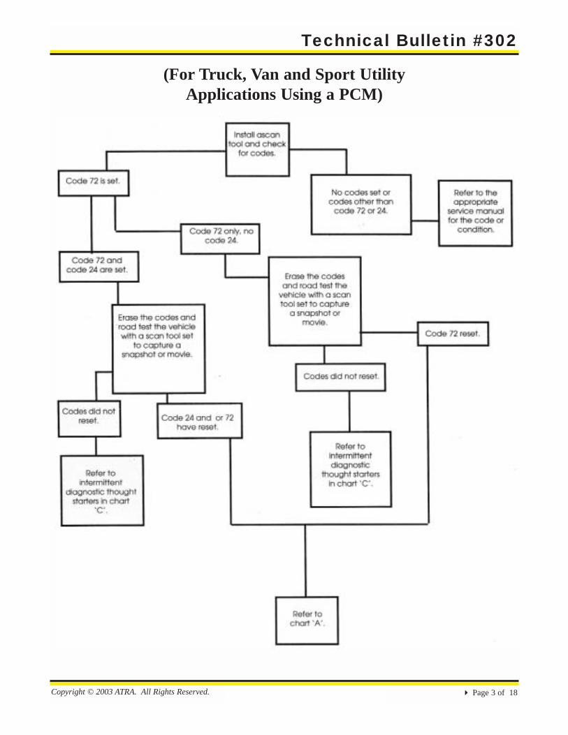
(For Truck, Van and Sport UtilityApplications Using a PCM)

Technical Bulletin #302
Copyright © 2003 ATRA. All Rights Reserved.! Page 4 of 18
Chart ‘A’Code 72 or 72 and 24

Technical Bulletin #302
Copyright © 2003 ATRA. All Rights Reserved. ! Page 5 of 18
Chart ‘B’Scanner Indicates 0 MPH
and 0 Output RPM

Technical Bulletin #302
Copyright © 2003 ATRA. All Rights Reserved.! Page 6 of 18
Gas Engine
HOT IN RUNVEHICLESPEEDSENSORBUFFER
FUSEBLOCK
BRAKEFUSE15 AMP
MEASURINGAND HANDLINGPROCEDURES
SOLID-STATE
ELECTRONICCLUSTER
POWERTRAINCONTROLMODULE (PCM)
VEHCILESPEEDSENSOR
CRUISECONTROLMODULE
G150I/PGROUND
PCM CONNECTOR IDENTIFICATION
C204 - BLUE - 32 WAYC288 - RED - 32 WAY
SEE FUSEBLOCK DETAILS
C14 C11 C10 C12 C13 C9 C8 C7 C1C231 C267
S296
C206
C240
JC240
C101
C187
P100
SEE GROUNDDISTRIBUTION
.8 LTBLU/BLK
824
.8 LTBLU/BLK
824
B
.8DK
BLU1716 1
WHT 696
1WHT 696
1WHT 696
1WHT 696
D
4WAL MODULE PIN F
.5 PPL/WHT 821
.5 PPL/WHT 821
.5 PPL/WHT 821
.5 PPL/WHT 821
TWISTEDPAIR
TWISTEDPAIR
G
TWISTEDPAIR
A B
.8 PNK/WHT 350
.8 LTGRN/BLK
822
.8 LTGRN/BLK
822
.8 LTGRN/BLK
822
C394
.8BLK 150
.8BLK 150
3 BLK 150
C101
3 BLK 150
S208
.8YEL 400
.8YEL 400
D
.8PNK/WHT
350
.8BRN 437
EF
.8DK
BLU1716
F13 F12
.8BRN 437
Technical Bulletin #302
Copyright © 2003 ATRA. All Rights Reserved. ! Page 7 of 18
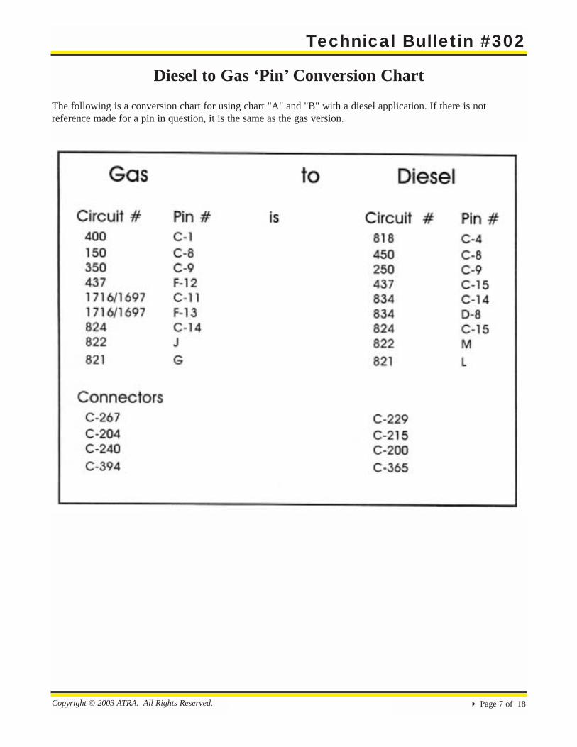
Diesel to Gas ‘Pin’ Conversion ChartThe following is a conversion chart for using chart "A" and "B" with a diesel application. If there is not reference made for a pin in question, it is the same as the gas version.

Technical Bulletin #302
Copyright © 2003 ATRA. All Rights Reserved.! Page 8 of 18
Diesel Engines
HOT IN RUNVEHICLESPEEDSENSORBUFFER
FUSEBLOCK
BRAKEFUSE15 AMP
MEASURINGAND HANDLINGPROCEDURES
SOLID-STATE
C11 C15 C14 C10 C12 C13 C9 C8 C7C289
C4C229
CRUISECONTROLMODULE
PCM CONNECTOR IDENTIFICATION
C215 - BLUE - 32 WAYC216 - RED - 32 WAY
SEE FUSEBLOCK DETAILS
TWISTEDPAIR
TWISTEDPAIR
TWISTEDPAIR
4WAL MODULE PIN F
RWAL MODULE PIN D
POWERTRAINCONTROLMODULE
SPEEDSENSOR
SEE GROUNDDISTRIBUTION
.8 LTGRN/BLK
822
.8 LTGRN/BLK
822
.8 LTGRN/BLK
822
C216C15
D8C215
C216
INSTRUMENTCLUSTER
CONVENIENCECENTER
BA C
.8 BRN/WHT 1586
.8 BRN/WHT 1586
C200
ZT C
.8 BRN 834
.8 BRN 437
.8 BRN 437
.8 BRN 834
S
.8 LTBLU/BLK
824
.8 BRN 437
.8 PPL/WHT 821
.8 PPL/WHT 821
.8 PPL/WHT 821
.8 PPL/WHT 821
C100
MLC200
P101
C365AB
.8 WHT 696
.8 WHT 696
DATA LINKCONNECTOR
.8 WHT 696
(RWAL)C2(4WAL)B2
G109ENGINEGROUND
.8 BRN 250
.8 BRN 250.8 BLK/WHT
450
.8 BLK/WHT
450
.8 BLK/WHT
450
.8 BLK/WHT
450
1 BLK/WHT 450
S136
C290
P101
C200
S240
R
S290
.8 RED/WHT
818
.8 RED/WHT
818
.8 RED/WHT
818
P102
K
39 450818

Technical Bulletin #302
Copyright © 2003 ATRA. All Rights Reserved. ! Page 9 of 18
Code Diagnosis Chart ‘C’
Concerns common to all applications:
• Excess grease packed into a connector. An excessive amount of grease in a terminal connector can cause poorelectrical contact.
• The toothed-wheel for the VSS is loose on the output shaft.• Extension housing or output shaft bushing is loose.• Someone has added a ground for an add-on accessory, such as an alarm or two-way radio, to the PCM or
DRAC (VSS buffer) ground circuits.• An add-on accessory, such as an alarm or radio, is located too clse to the DRAC which can cause electro-
magnetic interference problems. This condition may be indicated by noting a speedometer reading with thevehicle sitting still shile the add-on device is powered up.
• Vehicle speed sensor, DRAC or PCM is faulty.• Loss of terminal pin tension for the female terminals in any connector. All terminals are designed to
withstand only a few connects and disconnects. Connecting and disconnectiong the system’s connectors willreduce the life expectancy of those terminals. This can allow an intermittent connection to coccur. Loss of pin tension will cause damage to most terminals. To check for proper pin tension use the appropriate terminal tension gauge or use a spare male terminal of the correct size. To check the PCM and DRAC terminals use a .03+” drill or carburetor gauge. Both the PCM and DRAC use micro-pack terminals (round). Simply feel fora moderate drag when the male pin is insterted and removed. Be sure to use the correct size and style of male terminal when testing for proper tension.
Common concerns specific to model
• Safari and Astro Vans............................................................pg. 10
• S-10/T-10 Truck, Blazer and Jimmy.....................................pg. 12
• C/K Full Size Pickup, Yukon, Tahoe,Suburban and Blazer..............................................................pg. 14
• G Series, Full-Size Van.........................................................pg. 15

Technical Bulletin #302
Copyright © 2003 ATRA. All Rights Reserved.! Page 10 of 18
Common concerns specific to model:Safari and Astro Van
• Short to ground in VSS sensor circuit 821 or 822, on all sheel drive versions. The problem is usually at thetransfer case whre the wiring harness is routed over the top. The harness generally rubs through on one of the flanges of the transfer case (figure 1).
• Short to ground in circuit 821 or 822 at the wiringclamp, behind the exhaust shield.
• Circuits 821 or 822 shorted at the engine cover bracket or valve cover.
• Water intusion into the PCM connector C-240, causing terminal corrosion. Connector C-240 is mounted under the passenger side of the dash, next to the PCM (figure 2). Water intrusion into this areais usually due to a windshield leak in the right cornerof the dash.Circuit 420 (TCC) of the main harness is shorted toground on the right-hand side of the engine (the wirerubs through on the engine cover bracket). This condition will also result in the transmission going to default mode, and will greatly affect other vehiclesystems. Other systems affected will include: theshift interlock solenoid,k speedometer and ABS... allof which will be inoperative since the problem willcause the brake fuse to fail, which is used to feed allof these brake systems.
• A loose or damaged toothed-wheel on the outputshaft which is used for the VSS.
• Poor connection at terminal j or g in connector C-240. If the connector is not fully latched, ABS code 37 may set in conjunction with code 72.

Technical Bulletin #302
Copyright © 2003 ATRA. All Rights Reserved. ! Page 11 of 18
• A loose or corroded battery ground bolt. This problem is generally ground G-102 (figure 3A) which is mounted under the water pump/power steering pump area of the block, or G-150 (figure 3B) which is mounted to the radiator core support. If these grounds ar not corroded or loose, inspect ground G-197 (figure 3C) for apossible problem. A problem with G-150 may also cause the dash lamps to be dim.
• Extension housing or output shaft bushing loose.• The vehicle speed sensor circuits are routed with the main vehicle harness. This harness travels along the
bellhousing and enters the cab on the passenger side. If the harness is too close to any spark plug wires, a code 72 will result due to EMI. Reroute the plug wires away from the P-100 (pass through connector) area (figure 2, page 10).
• Loss of battery voltage to the bulkhead connector. (The bulkhead connector is located on the driver’s side, close to the brake booster.)

Technical Bulletin #302
Copyright © 2003 ATRA. All Rights Reserved.! Page 12 of 18
S-10/T-10 Truck, Blazer and Jimmy
• Circuit 821 or 822 shorted to ground at the metal bracket below the distributor or as it crosses the top of the bellhousing (figure 4).
• Circuit 821 or 822 shorted to ground at the right hand valvecover area, heat stove or dipstick tube area.
• Short to ground in VSS circuit 821 (or 822, on four wheel drive versions). The problem is usually at the top of the transfer case where the wiring harness is routed over the top.The harness generally rubs through on one of the flanges of the transfer case, or becomes shorted to ground at one of the wiring harness hold-down clamps on the transmission.
• Ground G-104 or G-102 loose or corroded (figure 5). (G-104, G-102 are located at the rear of the cylinder head on4.3L applications, and on the passenger side, at the lower corner of the bellhousing on 2.2L applications).
• A short to ground in circuit 350 (ABS control module or brake switch), which will result in a brake fuse failing. Aproblem in this circuit is likely to result in an ABS code an service light. In addition, TcCC will not release and a malfunction in the operation of the cruise control will beapparent.
• Loose output or extension housing bushings on 2WD models.• A loose or damaged toothed-wheel on the output shaft which
is used for the VSS.

Technical Bulletin #302
Copyright © 2003 ATRA. All Rights Reserved. ! Page 13 of 18
• Connector C-212 is not fully connected or it’s terminals are damaged. C-212 is a 10-pin connector mounted next to the PCM (figure 6).
• The 4WD low-input circuit 1694, which feeds pin F-8 of the PCM may be intermittently shorting to ground. This will change the PCM’s ratio calculation for the VSS, which may result in setting code 72.
Technical Bulletin #302
Copyright © 2003 ATRA. All Rights Reserved.! Page 14 of 18
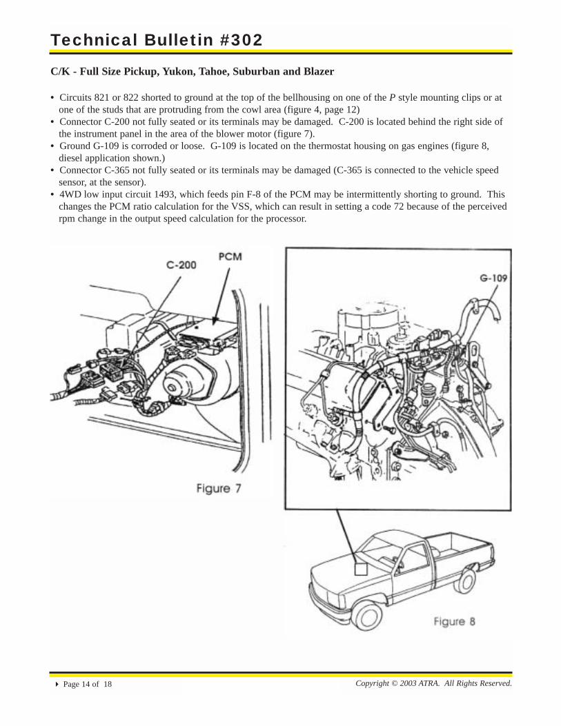
C/K - Full Size Pickup, Yukon, Tahoe, Suburban and Blazer
• Circuits 821 or 822 shorted to ground at the top of the bellhousing on one of the P style mounting clips or atone of the studs that are protruding from the cowl area (figure 4, page 12)
• Connector C-200 not fully seated or its terminals may be damaged. C-200 is located behind the right side of the instrument panel in the area of the blower motor (figure 7).
• Ground G-109 is corroded or loose. G-109 is located on the thermostat housing on gas engines (figure 8, diesel application shown.)
• Connector C-365 not fully seated or its terminals may be damaged (C-365 is connected to the vehicle speed sensor, at the sensor).
• 4WD low input circuit 1493, which feeds pin F-8 of the PCM may be intermittently shorting to ground. This changes the PCM ratio calculation for the VSS, which can result in setting a code 72 because of the perceived rpm change in the output speed calculation for the processor.

Technical Bulletin #302
Copyright © 2003 ATRA. All Rights Reserved. ! Page 15 of 18
G Series - Full Size Van
• Circuits 821or 822 are shorted to ground at the P style hold-down clamp on the side of the transmission (fig-ure 9). These circuits have also been known to short to grounnd on the underdash bracket near the DRAC. TheDRAC is located on the driver’s side under the dash (figure 10, page 16).

Technical Bulletin #302
Copyright © 2003 ATRA. All Rights Reserved.! Page 16 of 18
• Ground G-200 loose, not installed or corroded. G-200 is mounted under the driver’s side of the instrument cluster next to the fuse block. It may be necessary to add an extra ground for this location. Note: A poor ground for this circuit may also cause intermittent operation of other systems which rely on this ground for proper operation, such as the dome light and brake system circuits.
Technical Bulletin #302
Copyright © 2003 ATRA. All Rights Reserved. ! Page 17 of 18
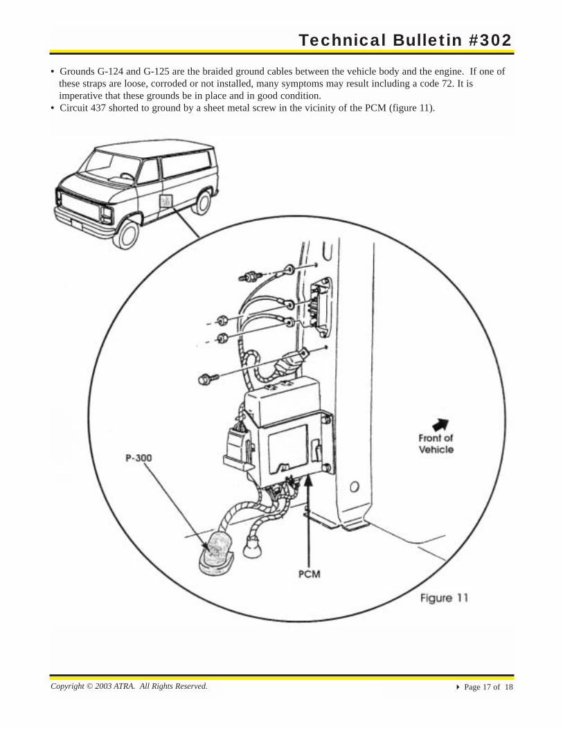
• Grounds G-124 and G-125 are the braided ground cables between the vehicle body and the engine. If one of these straps are loose, corroded or not installed, many symptoms may result including a code 72. It is imperative that these grounds be in place and in good condition.
• Circuit 437 shorted to ground by a sheet metal screw in the vicinity of the PCM (figure 11).
Technical Bulletin #302
Copyright © 2003 ATRA. All Rights Reserved.! Page 18 of 18
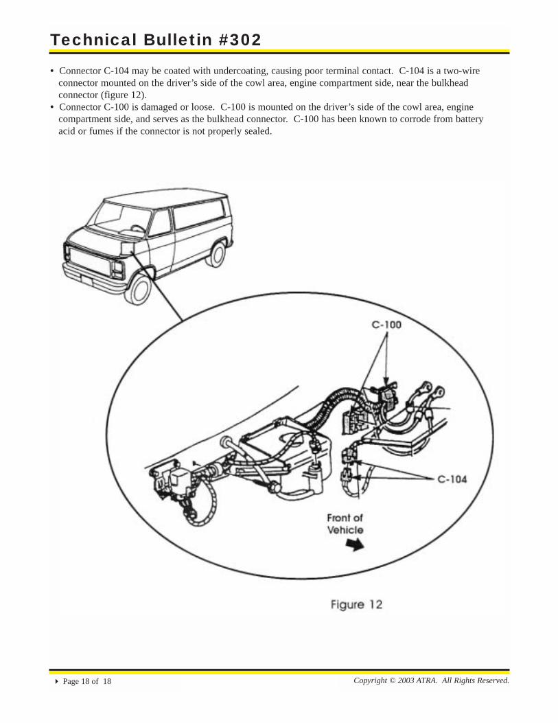
• Connector C-104 may be coated with undercoating, causing poor terminal contact. C-104 is a two-wire connector mounted on the driver’s side of the cowl area, engine compartment side, near the bulkhead connector (figure 12).
• Connector C-100 is damaged or loose. C-100 is mounted on the driver’s side of the cowl area, engine compartment side, and serves as the bulkhead connector. C-100 has been known to corrode from battery acid or fumes if the connector is not properly sealed.