4x35 profibus-dp system - eilersen.com · profibus-dp communication with the 4x35 profibus-dp unit...
TRANSCRIPT
Kokkedal Industripark 4
DK-2980 Kokkedal
Denmark
Tel +45 49 180 100
Fax +45 49 180 200
Applies for:
Program no.: WEIGHT.051103.1
Document no.: 1103mu4X35-1a.DOC
Date: 2017-06-30
Rev.: 1a
4X35 PROFIBUS-DP SYSTEM
Standard weight function for digital loadcells
4X35: User manual
WWW.EILERSEN.COM
Version: 2017-06-30, rev.: 1a Page: 2
1) CONTENTS
1) CONTENTS ..................................................................................................................................... 2 2) INTRODUCTION ........................................................................................................................... 3
2.1 Introduction ................................................................................................................................. 3 2.2 Profibus-DP specification ........................................................................................................... 3 2.3 Update times ............................................................................................................................... 3
3) DATA EXCHANGE ....................................................................................................................... 4 3.1 Profibus-DP communication using PPO ..................................................................................... 4 3.2 PCV Description ......................................................................................................................... 5 3.3 PCD Description ......................................................................................................................... 7
4) PARAMETER LIST ...................................................................................................................... 10 4.1 Parameter list ............................................................................................................................ 10
5) PARAMETER DESCRIPTION .................................................................................................... 12 5.1 Parameter description ................................................................................................................ 12
6) DATA PROCESSING ................................................................................................................... 15 6.1 Zeroing procedure ..................................................................................................................... 15 6.2 Calibration procedure ................................................................................................................ 15
7) INSTALATION OF SYSTEM ...................................................................................................... 17 7.1 Checklist during installation ..................................................................................................... 17
8) HARDWARE DESCRIPTION ..................................................................................................... 19 8.1 4X35 overview .......................................................................................................................... 19 8.2 4X35 front panel description .................................................................................................... 19
8.2.1 Connection of power ...................................................................................................... 19 8.2.2 Connection of loadcells .................................................................................................. 20 8.2.3 Profibus-DP connector ................................................................................................... 20 8.2.4 SW1 settings ................................................................................................................... 20 8.2.5 SWP settings .................................................................................................................. 20 8.2.6 Light Emitting Diodes (LEDs) ....................................................................................... 21
8.3 Hardware Selftest ...................................................................................................................... 21 9) APPENDIX .................................................................................................................................... 22
9.1 4035 Profibus-DP module ......................................................................................................... 22 9.1.1 SW3 settings ................................................................................................................... 22 9.1.2 Jumper settings ............................................................................................................... 23 9.1.3 JTAG connector ............................................................................................................. 23
9.2 4040 communication module .................................................................................................... 23 9.3 Status codes ............................................................................................................................... 24 9.4 Data formats .............................................................................................................................. 25
9.4.1 Unsigned integer format (16 bit) .................................................................................... 25 9.4.2 Signed integer format (32 bit) ........................................................................................ 25 9.4.3 IEEE754 floating point format (32 bit) .......................................................................... 26
10) APPENDIX – PROFIBUS CONFIGURATION TIPS................................................................ 27 10.1 GSD File ................................................................................................................................. 27
10.1.1 Input/Output modules and data sizes ............................................................................. 27
4X35: User manual
WWW.EILERSEN.COM
Version: 2017-06-30, rev.: 1a Page: 3
2) INTRODUCTION
2.1 Introduction
This document describes the use of a 4X35 Profibus-DP system unit from Eilersen Elec-
tric. The 4X35 system unit consists internally of a 4035 Profibus-DP module (with the
program listed on the front page) and a 4040 communication module.
The 4X35 system unit is connected to X loadcells (1-4). With the program specified on the
front page, the 4X35 Profibus-DP unit can act as a single system weight for up to 4
loadcells.
It is possible to connect the 4X35 Profibus-DP unit to a Profibus-DP network, where it will
act as a slave. It will then be possible from the Profibus-DP master to read status, read sys-
tem weight and perform commands such as zeroing and calibration.
Exchange of data between master and slave takes place as described in the following.
2.2 Profibus-DP specification
The Profibus-DP unit confirms to the following Profibus-DP specifications:
Protocol: Profibus-DP
Communications form: RS485
Module type: Slave
Baud rates [kbit/sec]: 9.6, 19.2, 93.75, 187.5, 500, 1500, 3000, 6000, 12000
Profibus address: 0-127
Profibus connection: 9-pin sub-D (female) connector
2.3 Update times
The 4X35 Profibus-DP system unit samples the loadcell signals over a period of 200 mS. The
hereby found loadcell signals are used in the Profibus-DP communication until new signals
are achieved when the next sample period expires. Update times across the Profibus-DP
communication depends on the specific Profibus-DP configuration (selected baudrate, num-
ber of slaves, scan times etc.).

4X35: User manual
WWW.EILERSEN.COM
Version: 2017-06-30, rev.: 1a Page: 4
3) DATA EXCHANGE
3.1 Profibus-DP communication using PPO
Profibus-DP communication with the 4X35 Profibus-DP unit uses a so called 'parameter-
process data object' (PPO) consisting of 14 bytes. This object is used during reception as well
as during transmission of data. The structure of this telegram is as follows:
PCV PCD
PCA IND PVA CTW
STW MRV
MAV
1 2 3 4 5 6 7 8 9 10 11 12 13 14
Byte 1 Byte 14
The telegram is made up of two blocks; a PCV part (the first 8 bytes) and a PCD part (the
last 6 bytes). The two blocks are made up as follows:
PCV (Parameter-Characteristic-Value)
PCA (Bytes 1-2): Parameter Characteristics
IND (Bytes 3-4): Not used (reserved for future use)
PVA (Bytes 5-8): Parameter value
PCD (Process Data)
CTW (Bytes 9-10) (Master to Slave): Control Word
STW (Bytes 9-10) (Slave to Master): Status Word
MRV (Bytes 11-14) (Master to Slave): Main Reference Value
MAV (Bytes 11-14) (Slave to Master): Main Actual Value
In the following the meaning of the individual blocks in the telegram is described in detail.
The byte order (MSB/LSB first) for the individual parts is selected using jumper JU8, and
upon factory delivery it is default set to MSB byte first.
The data format of the MAV part and parameters in the PVA part is 32 bit signed integer
format (2’s complement). It is possible however, by using of jumper JU7 to change so that
the MAV part and certain parameters in the PVA part are transferred in IEEE754 floating
point format.
During transmission/reception of data consisting of several bytes (for example the MAV) it
is up to the master (the PLC) to provide for consistent (belonging together) data.
4X35: User manual
WWW.EILERSEN.COM
Version: 2017-06-30, rev.: 1a Page: 5
3.2 PCV Description
The PCV part of the telegram is as mentioned made up of a PCA part, an IND part and a PVA
part. As mentioned the IND part is not used, but the functionality of the other two parts of the
PCV is described here.
PCA handling
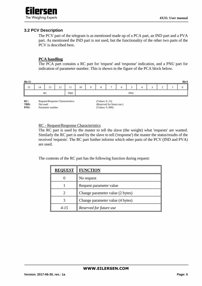
The PCA part contains a RC part for 'request' and 'response' indication, and a PNU part for
indication of parameter number. This is shown in the figure of the PCA block below.
Bit 15 Bit 0
15 14 13 12 11 10 9 8 7 6 5 4 3 2 1 0
RC TBD PNU
RC: Request/Response Characteristics (Values: 0..15)
TBD: Not used (Reserved for future use.) PNU: Parameter number (Values: 0..999)
RC - Request/Response Characteristics
The RC part is used by the master to tell the slave (the weight) what 'requests' are wanted.
Similarly the RC part is used by the slave to tell ('response') the master the status/results of the
received 'requests'. The RC part further informs which other parts of the PCV (IND and PVA)
are used.
The contents of the RC part has the following function during request:
REQUEST FUNCTION
0 No request
1 Request parameter value
2 Change parameter value (2 bytes)
3 Change parameter value (4 bytes)
4-15 Reserved for future use
4X35: User manual
WWW.EILERSEN.COM
Version: 2017-06-30, rev.: 1a Page: 6
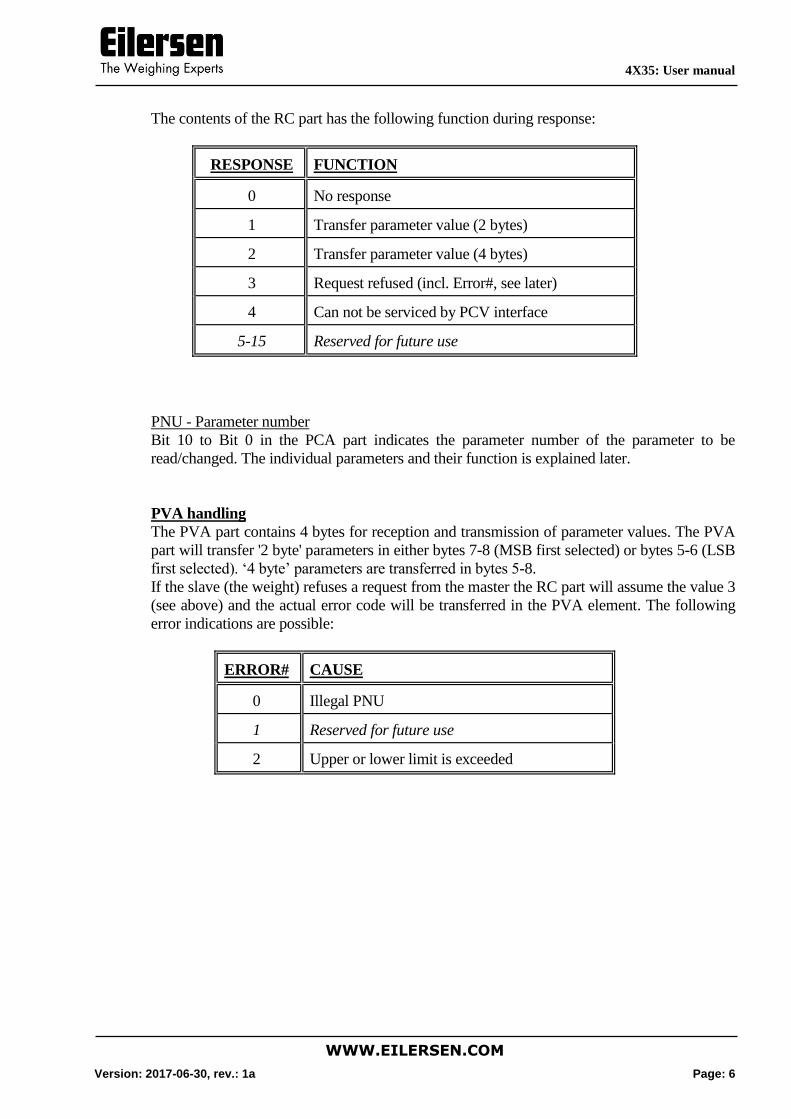
The contents of the RC part has the following function during response:
RESPONSE FUNCTION
0 No response
1 Transfer parameter value (2 bytes)
2 Transfer parameter value (4 bytes)
3 Request refused (incl. Error#, see later)
4 Can not be serviced by PCV interface
5-15 Reserved for future use
PNU - Parameter number
Bit 10 to Bit 0 in the PCA part indicates the parameter number of the parameter to be
read/changed. The individual parameters and their function is explained later.
PVA handling
The PVA part contains 4 bytes for reception and transmission of parameter values. The PVA
part will transfer '2 byte' parameters in either bytes 7-8 (MSB first selected) or bytes 5-6 (LSB
first selected). ‘4 byte’ parameters are transferred in bytes 5-8.
If the slave (the weight) refuses a request from the master the RC part will assume the value 3
(see above) and the actual error code will be transferred in the PVA element. The following
error indications are possible:
ERROR# CAUSE
0 Illegal PNU
1 Reserved for future use
2 Upper or lower limit is exceeded
4X35: User manual
WWW.EILERSEN.COM
Version: 2017-06-30, rev.: 1a Page: 7
3.3 PCD Description
As mentioned the PCD part of the telegram is made up of a CTW/STW part and a
MRV/MAV part. The functionality of the PCD parts is described here. Note that the PCD part
(the last 6 bytes) always transfers these data independent of the contents of the PCV part (the
first 8 bytes).
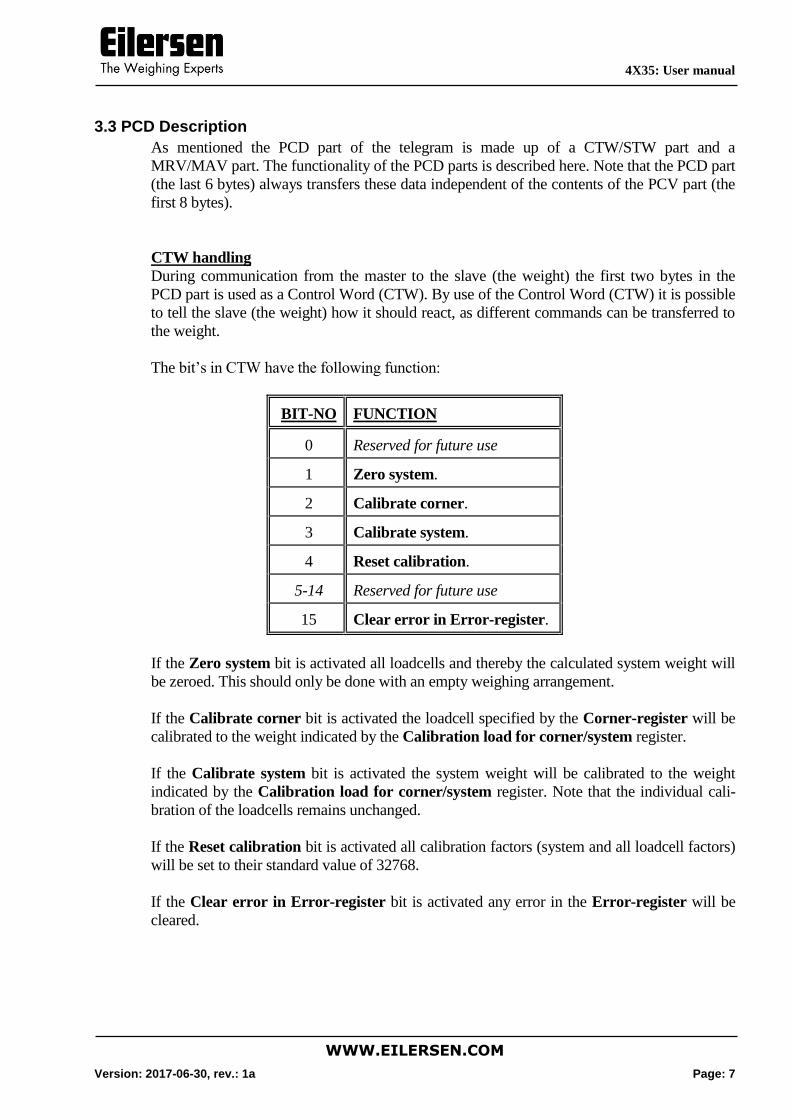
CTW handling
During communication from the master to the slave (the weight) the first two bytes in the
PCD part is used as a Control Word (CTW). By use of the Control Word (CTW) it is possible
to tell the slave (the weight) how it should react, as different commands can be transferred to
the weight.
The bit’s in CTW have the following function:
BIT-NO FUNCTION
0 Reserved for future use
1 Zero system.
2 Calibrate corner.
3 Calibrate system.
4 Reset calibration.
5-14 Reserved for future use
15 Clear error in Error-register.
If the Zero system bit is activated all loadcells and thereby the calculated system weight will
be zeroed. This should only be done with an empty weighing arrangement.
If the Calibrate corner bit is activated the loadcell specified by the Corner-register will be
calibrated to the weight indicated by the Calibration load for corner/system register.
If the Calibrate system bit is activated the system weight will be calibrated to the weight
indicated by the Calibration load for corner/system register. Note that the individual cali-
bration of the loadcells remains unchanged.
If the Reset calibration bit is activated all calibration factors (system and all loadcell factors)
will be set to their standard value of 32768.
If the Clear error in Error-register bit is activated any error in the Error-register will be
cleared.
4X35: User manual
WWW.EILERSEN.COM
Version: 2017-06-30, rev.: 1a Page: 8
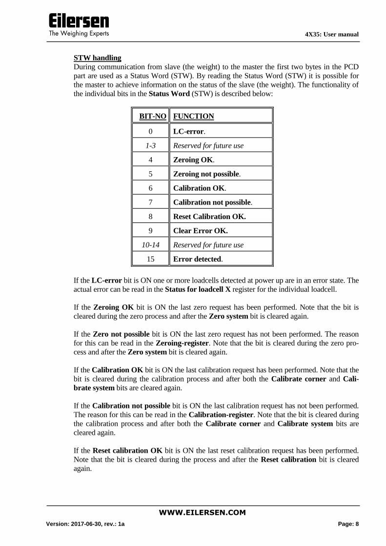
STW handling
During communication from slave (the weight) to the master the first two bytes in the PCD
part are used as a Status Word (STW). By reading the Status Word (STW) it is possible for
the master to achieve information on the status of the slave (the weight). The functionality of
the individual bits in the Status Word (STW) is described below:
BIT-NO FUNCTION
0 LC-error.
1-3 Reserved for future use
4 Zeroing OK.
5 Zeroing not possible.
6 Calibration OK.
7 Calibration not possible.
8 Reset Calibration OK.
9 Clear Error OK.
10-14 Reserved for future use
15 Error detected.
If the LC-error bit is ON one or more loadcells detected at power up are in an error state. The
actual error can be read in the Status for loadcell X register for the individual loadcell.
If the Zeroing OK bit is ON the last zero request has been performed. Note that the bit is
cleared during the zero process and after the Zero system bit is cleared again.
If the Zero not possible bit is ON the last zero request has not been performed. The reason
for this can be read in the Zeroing-register. Note that the bit is cleared during the zero pro-
cess and after the Zero system bit is cleared again.
If the Calibration OK bit is ON the last calibration request has been performed. Note that the
bit is cleared during the calibration process and after both the Calibrate corner and Cali-
brate system bits are cleared again.
If the Calibration not possible bit is ON the last calibration request has not been performed.
The reason for this can be read in the Calibration-register. Note that the bit is cleared during
the calibration process and after both the Calibrate corner and Calibrate system bits are
cleared again.
If the Reset calibration OK bit is ON the last reset calibration request has been performed.
Note that the bit is cleared during the process and after the Reset calibration bit is cleared
again.
4X35: User manual
WWW.EILERSEN.COM
Version: 2017-06-30, rev.: 1a Page: 9
If the Clear error OK bit is ON the last clear error request has been performed. Note that the
bit is cleared during the process and after the Clear error in Error-register bit is cleared
again.
If the Error detected bit is ON the system has detected an error. The actual error can be
found in the Error-register.
MRV handling
During communication from the master to the slave (the weight) the four last bytes in the
PCD part are used as a Main Reference Value (MRV); a setpoint. The Main Reference Val-
ue (MRV) has no function in this program.
MAV handling
During communication from the slave (the weight) to the master the four last bytes in the
PCD part are used as a Main Actual Value (MAV); the actual value. The Main Actual Value
(MAV) is used to transfer the actual gross weight of the system. The gross weight must be
scaled in accordance to the Exponent for MAV parameter (Par.No.=15) if Gram mode has
not been selected using jumper JU1. Default factory setting is that Gram mode is not select-
ed. Note that the MAV part may be transferred in 32 bit signed integer format (default) or in
IEEE754 floating point format depending on the actual jumper setting.
4X35: User manual
WWW.EILERSEN.COM
Version: 2017-06-30, rev.: 1a Page: 10
4) PARAMETER LIST
4.1 Parameter list
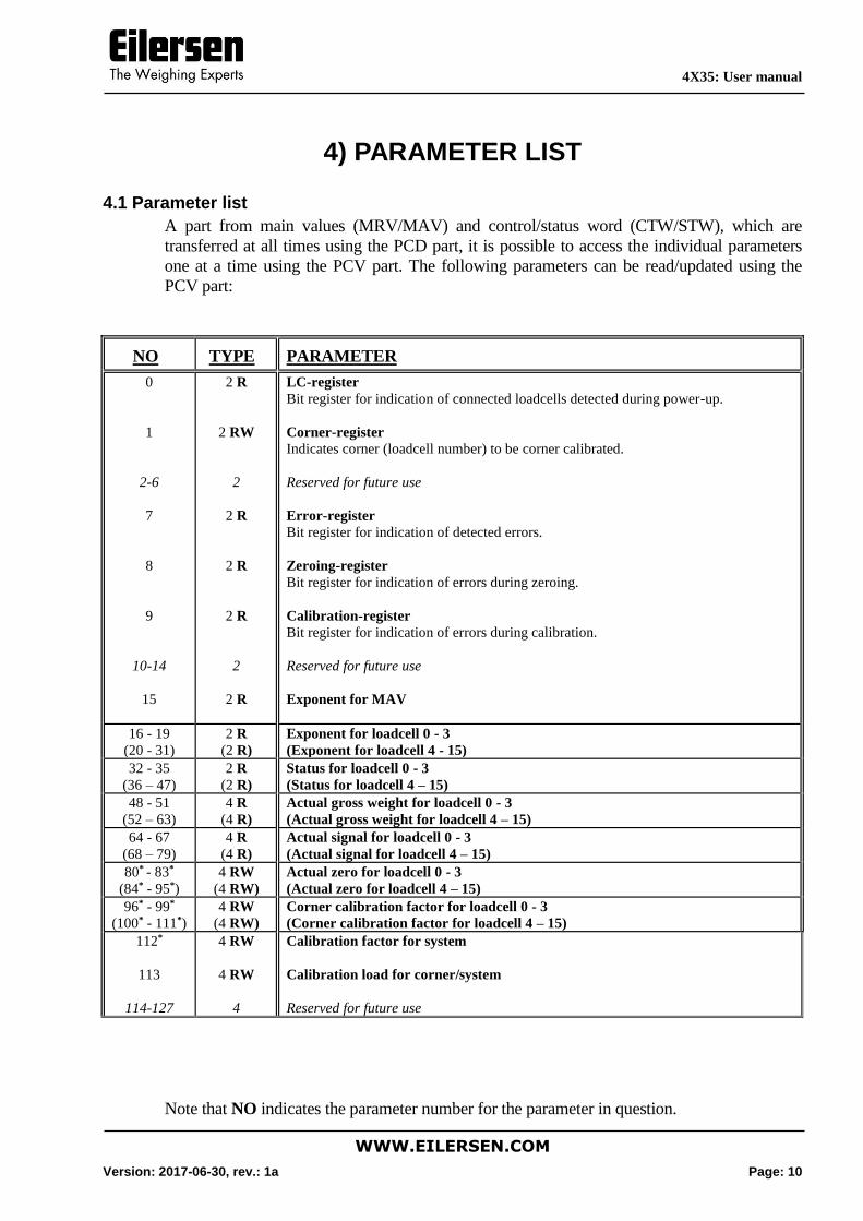
A part from main values (MRV/MAV) and control/status word (CTW/STW), which are
transferred at all times using the PCD part, it is possible to access the individual parameters
one at a time using the PCV part. The following parameters can be read/updated using the
PCV part:
NO TYPE PARAMETER
0
1
2-6
7
8
9
10-14
15
2 R
2 RW
2
2 R
2 R
2 R
2
2 R
LC-register
Bit register for indication of connected loadcells detected during power-up.
Corner-register
Indicates corner (loadcell number) to be corner calibrated.
Reserved for future use
Error-register
Bit register for indication of detected errors.
Zeroing-register
Bit register for indication of errors during zeroing.
Calibration-register
Bit register for indication of errors during calibration.
Reserved for future use
Exponent for MAV
16 - 19
(20 - 31)
2 R
(2 R)
Exponent for loadcell 0 - 3
(Exponent for loadcell 4 - 15)
32 - 35
(36 – 47)
2 R
(2 R)
Status for loadcell 0 - 3
(Status for loadcell 4 – 15)
48 - 51
(52 – 63)
4 R
(4 R)
Actual gross weight for loadcell 0 - 3
(Actual gross weight for loadcell 4 – 15)
64 - 67
(68 – 79)
4 R
(4 R)
Actual signal for loadcell 0 - 3
(Actual signal for loadcell 4 – 15)
80* - 83*
(84* - 95*)
4 RW
(4 RW)
Actual zero for loadcell 0 - 3
(Actual zero for loadcell 4 – 15)
96* - 99*
(100* - 111*)
4 RW
(4 RW)
Corner calibration factor for loadcell 0 - 3
(Corner calibration factor for loadcell 4 – 15)
112*
113
114-127
4 RW
4 RW
4
Calibration factor for system
Calibration load for corner/system
Reserved for future use
Note that NO indicates the parameter number for the parameter in question.
4X35: User manual
WWW.EILERSEN.COM
Version: 2017-06-30, rev.: 1a Page: 11
Note that TYPE indicates the length of the parameter in question (2 = 2 bytes and 4 = 4
bytes). In addition after the length it is indicated whether its a read and write register (RW =
ReadWrite) or its a read only register (R = Read).
Note that data values are transferred as 2 complement signed values.
Note that a * after the parameter number indicates that the parameter in question is stored in
the SEEPROM of the module, why this parameter can be remembered after power has been
disconnected. Please note that no zeroing or calibration is performed at power-up.
4X35: User manual
WWW.EILERSEN.COM
Version: 2017-06-30, rev.: 1a Page: 12
5) PARAMETER DESCRIPTION
5.1 Parameter description
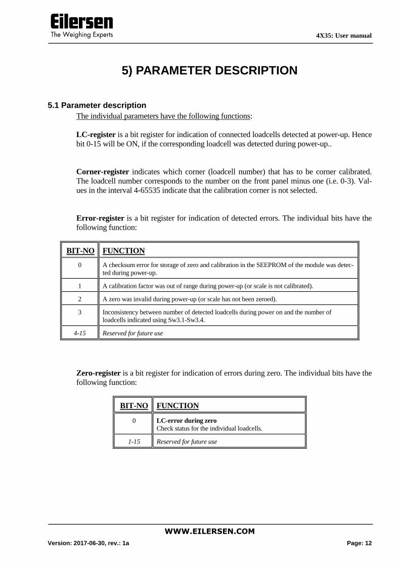
The individual parameters have the following functions:
LC-register is a bit register for indication of connected loadcells detected at power-up. Hence
bit 0-15 will be ON, if the corresponding loadcell was detected during power-up..
Corner-register indicates which corner (loadcell number) that has to be corner calibrated.
The loadcell number corresponds to the number on the front panel minus one (i.e. 0-3). Val-
ues in the interval 4-65535 indicate that the calibration corner is not selected.
Error-register is a bit register for indication of detected errors. The individual bits have the
following function:
BIT-NO FUNCTION
0 A checksum error for storage of zero and calibration in the SEEPROM of the module was detec-
ted during power-up.
1 A calibration factor was out of range during power-up (or scale is not calibrated).
2 A zero was invalid during power-up (or scale has not been zeroed).
3 Inconsistency between number of detected loadcells during power on and the number of
loadcells indicated using Sw3.1-Sw3.4.
4-15 Reserved for future use
Zero-register is a bit register for indication of errors during zero. The individual bits have the
following function:
BIT-NO FUNCTION
0 LC-error during zero
Check status for the individual loadcells.
1-15 Reserved for future use

4X35: User manual
WWW.EILERSEN.COM
Version: 2017-06-30, rev.: 1a Page: 13
Calibration-register is a bit register for indication of errors during calibration. The individual
bits have the following function:
BIT-NO FUNCTION
0 LC-error during calibration
Check status for the individual loadcells.
1 Calibration load not selected/valid
Check that a valid calibration load has been selected.
2 Calibration corner not selected/valid
Check that a valid calibration corner has been selected.
3 Calibration range exceeded
It was not possible to calibrate the system within the valid calibration range. Check
that nothing is affecting the weighing arrangement mechanically. Check that the
value in the Calibration load for corner/system register corresponds to the actual
load.
4 Gross weight was negative during calibration
Check the gross weight and whether it shows zero without any load.
5-15 Reserved for future use
Exponent for MAV is a register containing the exponent for the MAV. If Gram mode has
not been selected using jumper JU1, the transferred gross weight has to be compared with this
exponent. It indicates the "resolution” of the MAV (gross weight) as described under Expo-
nent for loadcell X. The exponent corresponds to the smallest loadcell exponent.
Exponent for loadcell X is a register containing the exponent of loadcell X. The transferred
weighing result has to be compared with the exponent for the loadcells. The exponent is a
fixed value (2 complement) for a given loadcell, and it indicates the "resolution" of the
loadcell (weighing result) as follows:
Exponent
[Decimal]
Exponent
[Hexadecimal]
Conversion factor
to gram
SI unit
-3 0xFFFD *10-3 mg
-2 0xFFFE *10-2
-1 0xFFFF *10-1
0 0x0000 *100 gram
1 0x0001 *101
2 0x0002 *102
3 0x0003 *103 Kg
4 0x0004 *104
5 0x0005 *105
6 0x0006 *106 ton
Status for loadcell X is a register containing the actual status for loadcell X. The meaning of
4X35: User manual
WWW.EILERSEN.COM
Version: 2017-06-30, rev.: 1a Page: 14
the status code can be found in the STATUS CODES chapter.
Actual gross weight for loadcell X contains the actual gross weight for loadcell X. The gross
weight is the actual load signal for the loadcell adjusted by zero and calibration factor. Note
that the value is a value averaged over 200 ms.
Actual signal for loadcell X contains the actual signal for loadcell X. The actual signal is the
actual load signal for the loadcell without any adjustment fir zero and calibration factor. Note
that the value is a value averaged over 200 ms.
Actual zero for loadcell X contains the actual zero value for loadcell X. The value is deter-
mined during zero from Actual signal for loadcell X.
Corner calibration factor for loadcell X contains the calibration factor for loadcell X. The
value is determined during calibration of corner X, and lies in the interval 24576-40960 with
32768 as center value (standard calibration factor corresponding to no calibration).
Calibration factor for system contains the system calibration factor. The value is determined
during calibration of the system, and lies in the interval 24576-40960 with 32768 as center
value (standard calibration factor corresponding to no calibration).
Calibration load for corner/system must contain the load used during calibration of the sys-
tem or corner. Note that this parameter is always transferred in the same format as the MAV.
The format may vary depending on the actual jumper settings (MSB/LSB first, SI32/IEEE754
format and Standard/Gram mode).
4X35: User manual
WWW.EILERSEN.COM
Version: 2017-06-30, rev.: 1a Page: 15
6) DATA PROCESSING
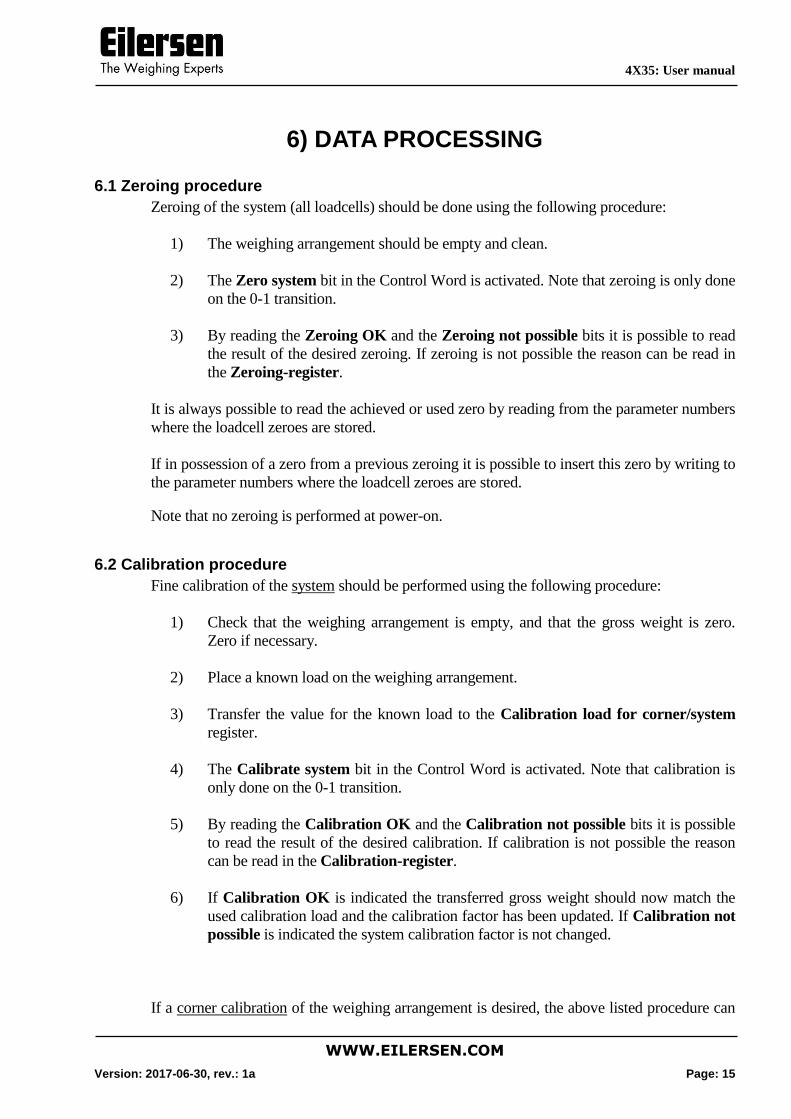
6.1 Zeroing procedure
Zeroing of the system (all loadcells) should be done using the following procedure:
1) The weighing arrangement should be empty and clean.
2) The Zero system bit in the Control Word is activated. Note that zeroing is only done
on the 0-1 transition.
3) By reading the Zeroing OK and the Zeroing not possible bits it is possible to read
the result of the desired zeroing. If zeroing is not possible the reason can be read in
the Zeroing-register.
It is always possible to read the achieved or used zero by reading from the parameter numbers
where the loadcell zeroes are stored.
If in possession of a zero from a previous zeroing it is possible to insert this zero by writing to
the parameter numbers where the loadcell zeroes are stored.
Note that no zeroing is performed at power-on.
6.2 Calibration procedure
Fine calibration of the system should be performed using the following procedure:
1) Check that the weighing arrangement is empty, and that the gross weight is zero.
Zero if necessary.
2) Place a known load on the weighing arrangement.
3) Transfer the value for the known load to the Calibration load for corner/system
register.
4) The Calibrate system bit in the Control Word is activated. Note that calibration is
only done on the 0-1 transition.
5) By reading the Calibration OK and the Calibration not possible bits it is possible
to read the result of the desired calibration. If calibration is not possible the reason
can be read in the Calibration-register.
6) If Calibration OK is indicated the transferred gross weight should now match the
used calibration load and the calibration factor has been updated. If Calibration not
possible is indicated the system calibration factor is not changed.
If a corner calibration of the weighing arrangement is desired, the above listed procedure can

4X35: User manual
WWW.EILERSEN.COM
Version: 2017-06-30, rev.: 1a Page: 16
still be used as the following is taken into account:
1) Corner calibration should be performed prior to system calibration. During corner
calibration the Calibration factor for system should be set to its standard value of
32768.
2) Corner calibration is done one corner at a time, where the above listed procedure is
used for each corner.
3) The actual calibration corner is selected in the Corner-register prior to start of cor-
ner calibration. The corner number corresponds to the loadcell number (on the front
panel of the system unit) minus one (i.e. 0-3). If in doubt the loadcell number can be
verified by finding the Actual gross weight for loadcell X, which gives a corre-
sponding signal change when a load is placed/removed directly above the actual
loadcell.
4) It is the Calibrate corner bit in the Control Word (CTW), that has to be activated
and not the Calibrate system bit.
5) The used calibration load must be placed directly above the actual loadcell, so that it
is this loadcell that absorbs the "entire" load.
6) It is not the system gross weight, that has to be observed but the Actual gross
weight for loadcell X. If the other loadcells are completely unloaded, this value
should correspond with the system gross weight.
7) Every corner calibration only changes the calibration factor for the corresponding
corner. The other corner and system calibration factors remain unchanged.
It is always possible to read the achieved or used calibration factors by reading from the pa-
rameter numbers where the calibration factors are stored.
If in possession of calibration factors from a previous calibration, it is possible to insert these
by writing to the parameter numbers where the calibration factors are stored.
Note that no calibration is performed at power-on.

4X35: User manual
WWW.EILERSEN.COM
Version: 2017-06-30, rev.: 1a Page: 17
7) INSTALATION OF SYSTEM
7.1 Checklist during installation
During installation of the system the following should be checked:
1) If necessary the Profibus-DP master should be configured to communicate with the 4X35 Profibus-
DP system unit using the supplied GSD file. Please refer to appendix for tips using the supplied
GSD file.
2) The loadcells are mounted mechanically and connected to BNC connectors in the front panel of the
4X35 system unit.
3) The 4X35 Profibus-DP system unit is connected to the Profibus-DP network using the Profibus-DP
connector in the front panel of the 4X35 system unit. If necessary a possible termination of the Pro-
fibus-DP network is made at this Profibus-DP slave.
4) Use SW1 in the front panel of the 4X35 system unit to select any features specified in the separate
manual for the 4040 communication module.
5) Use SWP.2-SWP.8 in the front panel of the 4X35 system unit to select the communication address
of the 4X35 Profibus-DP system unit.
6) Power (24VDC) is applied at the 2 pole power connectors in the front panel of the 4X35 system
unit as described in the hardware section, and the Profibus-DP communication is started.
7) Verify that the PBE lamp (red) is NOT lit, and that the DES lamp (yellow) and the RTS lamp (yel-
low) are lit/flashing.
8) Verify that the TxLC lamp (yellow) is lit (turns on after approx. 5 seconds).
9) Verify that the two TxBB lamps (green) are lit (both lit after 10 seconds).
10) Verify that NONE of the 1, 2, 3 or 4 lamps (red) are lit.
11) Verify that the 4X35 Profibus-DP system unit has found the correct loadcells (Par.No.=0), and that
no loadcell error is indicated in the Status Word (STW).
12) Reset all calibration factors by using the Reset Calibration bit in the Control Word (CTW).
13) Zero the system weight with empty weighing arrangement by using the “Zeroing procedure” de-
scribed earlier.
14) Verify that every loadcell gives a signal (Par.No.=48-63) by placing a load directly above each
loadcell one after the other (possibly with a known load).
15) Place a known load on the weighing arrangement, and check that the system weight (MAV) corre-
sponds to the load. Does the master take the exponent (scaling) into account if Gram mode has not
been selected?
16) Zero the system weight with empty weighing arrangement by using the “Zeroing procedure” de-
scribed earlier.
17) Place a known load (as close to maximum load as possible) on the weighing arrangement.
18) If the system weight deviates to much from the actual load a fine calibration of the system is made
using the “Calibration procedure” described earlier.

4X35: User manual
WWW.EILERSEN.COM
Version: 2017-06-30, rev.: 1a Page: 18
The system is now installed and a final check is made before the system is taken into us-
age. Possibly make a note of all zeroes (Par.No.=80-95) and calibration factors
(Par.No,=96-112) for later use.
Note that in the above checklist no consideration has been made on which functions are
implemented on the Profibus-DP master.

4X35: User manual
WWW.EILERSEN.COM
Version: 2017-06-30, rev.: 1a Page: 19
8) HARDWARE DESCRIPTION
8.1 4X35 overview
The following figure is an overview of a 4X35 system unit with 4 loadcell connections (i.e.
a 4435 system unit):
8.2 4X35 front panel description
This chapter describes the connections, DIP-switch settings and lamp indications that are
available on the front panel of the 4X35 system unit.
8.2.1 Connection of power
The 4X35 system unit is powered by applying +24VDC on the green two pole connectors
(J2 and J3) as specified on the front panel of the 4X35 system unit. This powers the entire
4X35 system unit including the loadcells.
NOTE: If the loadcells are to be placed inside an EX area, then the 4X35 system unit itself
MUST be placed outside the EX area, and the 4X35 system unit MUST be supplied as fol-
lows:
1) The 2 pole connector (J3), located to the right above the 4 pole DIP-switch block, MUST be pow-
ered by a 4051A power supply (+24VDC ATEX approved) from Eilersen Electric.
4X35: User manual
WWW.EILERSEN.COM
Version: 2017-06-30, rev.: 1a Page: 20
2) The 2 pole connector (J2), located to the left above the 9 pole Sub-D connector (PROFIBUS),
MUST be powered by a separate +24VDC, that has NO connection to the ATEX approved
+24VDC from the above mentioned 4051A power supply.
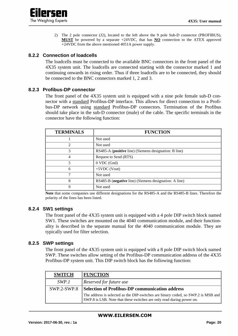
8.2.2 Connection of loadcells
The loadcells must be connected to the available BNC connectors in the front panel of the
4X35 system unit. The loadcells are connected starting with the connector marked 1 and
continuing onwards in rising order. Thus if three loadcells are to be connected, they should
be connected to the BNC connectors marked 1, 2 and 3.
8.2.3 Profibus-DP connector
The front panel of the 4X35 system unit is equipped with a nine pole female sub-D con-
nector with a standard Profibus-DP interface. This allows for direct connection to a Profi-
bus-DP network using standard Profibus-DP connectors. Termination of the Profibus
should take place in the sub-D connector (male) of the cable. The specific terminals in the
connector have the following function:
TERMINALS FUNCTION
1 Not used
2 Not used
3 RS485-A (positive line) (Siemens designation: B line)
4 Request to Send (RTS)
5 0 VDC (Gnd)
6 +5VDC (Vout)
7 Not used
8 RS485-B (negative line) (Siemens designation: A line)
9 Not used
Note that some companies use different designations for the RS485-A and the RS485-B lines. Therefore the
polarity of the lines has been listed.
8.2.4 SW1 settings
The front panel of the 4X35 system unit is equipped with a 4 pole DIP switch block named
SW1. These switches are mounted on the 4040 communication module, and their function-
ality is described in the separate manual for the 4040 communication module. They are
typically used for filter selection.
8.2.5 SWP settings
The front panel of the 4X35 system unit is equipped with a 8 pole DIP switch block named
SWP. These switches allow setting of the Profibus-DP communication address of the 4X35
Profibus-DP system unit. This DIP switch block has the following function:
SWITCH FUNCTION
SWP.1 Reserved for future use
SWP.2-SWP.8 Selection of Profibus-DP communication address
The address is selected as the DIP-switches are binary coded, so SWP.2 is MSB and
SWP.8 is LSB. Note that these switches are only read during power on.
4X35: User manual
WWW.EILERSEN.COM
Version: 2017-06-30, rev.: 1a Page: 21
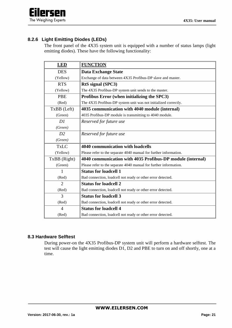
8.2.6 Light Emitting Diodes (LEDs)
The front panel of the 4X35 system unit is equipped with a number of status lamps (light
emitting diodes). These have the following functionality:
LED FUNCTION
DES
(Yellow)
Data Exchange State
Exchange of data between 4X35 Profibus-DP slave and master.
RTS
(Yellow)
RtS signal (SPC3)
The 4X35 Profibus-DP system unit sends to the master.
PBE
(Red)
Profibus Error (when initializing the SPC3)
The 4X35 Profibus-DP system unit was not initialized correctly.
TxBB (Left)
(Green)
4035 communication with 4040 module (internal)
4035 Profibus-DP module is transmitting to 4040 module.
D1
(Green)
Reserved for future use
D2
(Green)
Reserved for future use
TxLC
(Yellow)
4040 communication with loadcells
Please refer to the separate 4040 manual for further information.
TxBB (Right)
(Green)
4040 communication with 4035 Profibus-DP module (internal)
Please refer to the separate 4040 manual for further information.
1
(Red)
Status for loadcell 1
Bad connection, loadcell not ready or other error detected.
2
(Red)
Status for loadcell 2
Bad connection, loadcell not ready or other error detected.
3
(Red)
Status for loadcell 3
Bad connection, loadcell not ready or other error detected.
4
(Red)
Status for loadcell 4
Bad connection, loadcell not ready or other error detected.
8.3 Hardware Selftest
During power-on the 4X35 Profibus-DP system unit will perform a hardware selftest. The
test will cause the light emitting diodes D1, D2 and PBE to turn on and off shortly, one at a
time.
4X35: User manual
WWW.EILERSEN.COM
Version: 2017-06-30, rev.: 1a Page: 22
9) APPENDIX
9.1 4035 Profibus-DP module
This chapter describes possible connections, DIP-switch settings and jumper settings that
are available internally on the 4035 Profibus-DP module. These will normally be set from
Eilersen Electric and should only be changed in special situations.
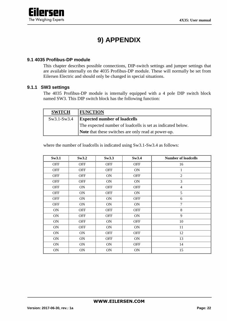
9.1.1 SW3 settings
The 4035 Profibus-DP module is internally equipped with a 4 pole DIP switch block
named SW3. This DIP switch block has the following function:
SWITCH FUNCTION
Sw3.1-Sw3.4 Expected number of loadcells
The expected number of loadcells is set as indicated below.
Note that these switches are only read at power-up.
where the number of loadcells is indicated using Sw3.1-Sw3.4 as follows:
Sw3.1 Sw3.2 Sw3.3 Sw3.4 Number of loadcells
OFF OFF OFF OFF 16
OFF OFF OFF ON 1
OFF OFF ON OFF 2
OFF OFF ON ON 3
OFF ON OFF OFF 4
OFF ON OFF ON 5
OFF ON ON OFF 6
OFF ON ON ON 7
ON OFF OFF OFF 8
ON OFF OFF ON 9
ON OFF ON OFF 10
ON OFF ON ON 11
ON ON OFF OFF 12
ON ON OFF ON 13
ON ON ON OFF 14
ON ON ON ON 15
4X35: User manual
WWW.EILERSEN.COM
Version: 2017-06-30, rev.: 1a Page: 23
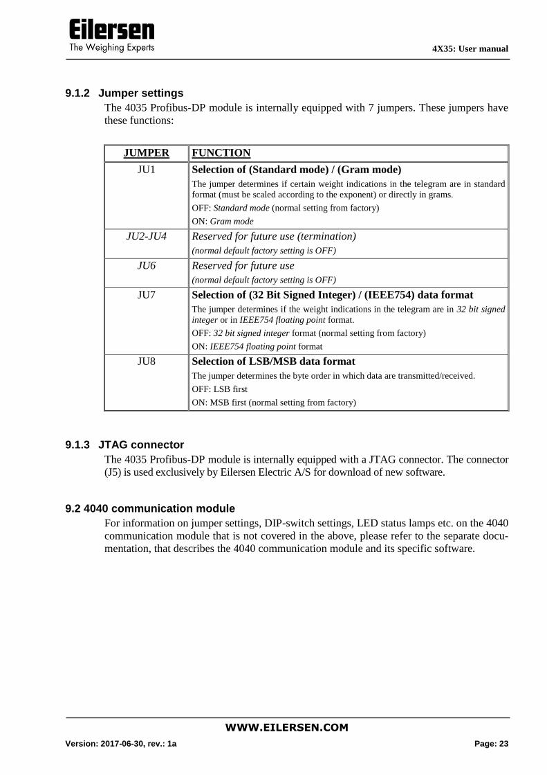
9.1.2 Jumper settings
The 4035 Profibus-DP module is internally equipped with 7 jumpers. These jumpers have
these functions:
JUMPER FUNCTION
JU1 Selection of (Standard mode) / (Gram mode)
The jumper determines if certain weight indications in the telegram are in standard
format (must be scaled according to the exponent) or directly in grams.
OFF: Standard mode (normal setting from factory)
ON: Gram mode
JU2-JU4 Reserved for future use (termination)
(normal default factory setting is OFF)
JU6 Reserved for future use
(normal default factory setting is OFF)
JU7 Selection of (32 Bit Signed Integer) / (IEEE754) data format
The jumper determines if the weight indications in the telegram are in 32 bit signed
integer or in IEEE754 floating point format.
OFF: 32 bit signed integer format (normal setting from factory)
ON: IEEE754 floating point format
JU8 Selection of LSB/MSB data format
The jumper determines the byte order in which data are transmitted/received.
OFF: LSB first
ON: MSB first (normal setting from factory)
9.1.3 JTAG connector
The 4035 Profibus-DP module is internally equipped with a JTAG connector. The connector
(J5) is used exclusively by Eilersen Electric A/S for download of new software.
9.2 4040 communication module
For information on jumper settings, DIP-switch settings, LED status lamps etc. on the 4040
communication module that is not covered in the above, please refer to the separate docu-
mentation, that describes the 4040 communication module and its specific software.
4X35: User manual
WWW.EILERSEN.COM
Version: 2017-06-30, rev.: 1a Page: 24
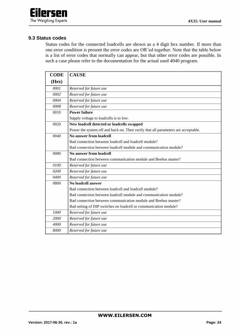
9.3 Status codes
Status codes for the connected loadcells are shown as a 4 digit hex number. If more than
one error condition is present the error codes are OR’ed together. Note that the table below
is a list of error codes that normally can appear, but that other error codes are possible. In
such a case please refer to the documentation for the actual used 4040 program.
CODE
(Hex)
CAUSE
0001 Reserved for future use
0002 Reserved for future use
0004 Reserved for future use
0008 Reserved for future use
0010 Power failure
Supply voltage to loadcells is to low.
0020 New loadcell detected or loadcells swapped
Power the system off and back on. Then verify that all parameters are acceptable.
0040 No answer from loadcell
Bad connection between loadcell and loadcell module?
Bad connection between loadcell module and communication module?
0080 No answer from loadcell
Bad connection between communication module and Beebus master?
0100 Reserved for future use
0200 Reserved for future use
0400 Reserved for future use
0800 No loadcell answer
Bad connection between loadcell and loadcell module?
Bad connection between loadcell module and communication module?
Bad connection between communication module and Beebus master?
Bad setting of DIP switches on loadcell or communication module?
1000 Reserved for future use
2000 Reserved for future use
4000 Reserved for future use
8000 Reserved for future use
4X35: User manual
WWW.EILERSEN.COM
Version: 2017-06-30, rev.: 1a Page: 25
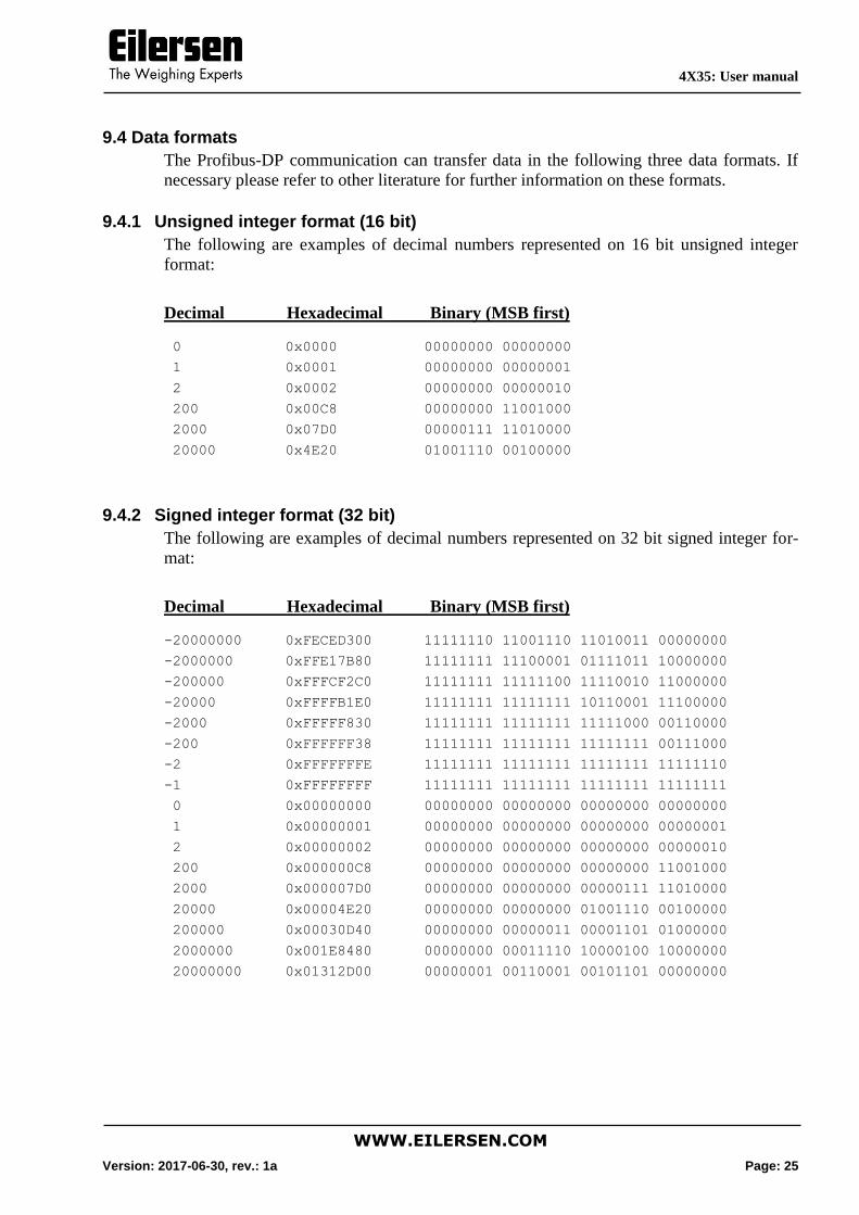
9.4 Data formats
The Profibus-DP communication can transfer data in the following three data formats. If
necessary please refer to other literature for further information on these formats.
9.4.1 Unsigned integer format (16 bit)
The following are examples of decimal numbers represented on 16 bit unsigned integer
format:
Decimal Hexadecimal Binary (MSB first)
0 0x0000 00000000 00000000
1 0x0001 00000000 00000001
2 0x0002 00000000 00000010
200 0x00C8 00000000 11001000
2000 0x07D0 00000111 11010000
20000 0x4E20 01001110 00100000
9.4.2 Signed integer format (32 bit)
The following are examples of decimal numbers represented on 32 bit signed integer for-
mat:
Decimal Hexadecimal Binary (MSB first)
-20000000 0xFECED300 11111110 11001110 11010011 00000000
-2000000 0xFFE17B80 11111111 11100001 01111011 10000000
-200000 0xFFFCF2C0 11111111 11111100 11110010 11000000
-20000 0xFFFFB1E0 11111111 11111111 10110001 11100000
-2000 0xFFFFF830 11111111 11111111 11111000 00110000
-200 0xFFFFFF38 11111111 11111111 11111111 00111000
-2 0xFFFFFFFE 11111111 11111111 11111111 11111110
-1 0xFFFFFFFF 11111111 11111111 11111111 11111111
0 0x00000000 00000000 00000000 00000000 00000000
1 0x00000001 00000000 00000000 00000000 00000001
2 0x00000002 00000000 00000000 00000000 00000010
200 0x000000C8 00000000 00000000 00000000 11001000
2000 0x000007D0 00000000 00000000 00000111 11010000
20000 0x00004E20 00000000 00000000 01001110 00100000
200000 0x00030D40 00000000 00000011 00001101 01000000
2000000 0x001E8480 00000000 00011110 10000100 10000000
20000000 0x01312D00 00000001 00110001 00101101 00000000
4X35: User manual
WWW.EILERSEN.COM
Version: 2017-06-30, rev.: 1a Page: 26
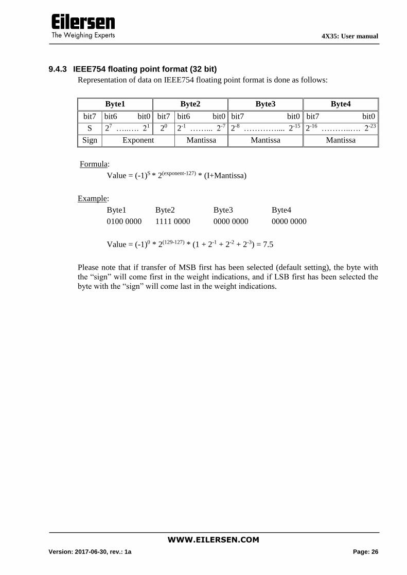
9.4.3 IEEE754 floating point format (32 bit)
Representation of data on IEEE754 floating point format is done as follows:
Byte1 Byte2 Byte3 Byte4
bit7 bit6 bit0 bit7 bit6 bit0 bit7 bit0 bit7 bit0
S 27 …..…. 21 20 2-1 ……... 2-7 2-8 ………….... 2-15 2-16 ………..…. 2-23
Sign Exponent Mantissa Mantissa Mantissa
Formula:
Value = (-1)S * 2(exponent-127) * (I+Mantissa)
Example:
Byte1 Byte2 Byte3 Byte4
0100 0000 1111 0000 0000 0000 0000 0000
Value = (-1)0 * 2(129-127) * (1 + 2-1 + 2-2 + 2-3) = 7.5
Please note that if transfer of MSB first has been selected (default setting), the byte with
the “sign” will come first in the weight indications, and if LSB first has been selected the
byte with the “sign” will come last in the weight indications.
4X35: User manual
WWW.EILERSEN.COM
Version: 2017-06-30, rev.: 1a Page: 27
10) APPENDIX – PROFIBUS CONFIGURATION TIPS
10.1 GSD File
The supplied GSD file can be used to configure the PROFIBUS master (PLC) to com-
municate with the 4x35 PROFIBUS unit.
When configuring the PROFIBUS master using the supplied GSD file please note the fol-
lowing tips.
10.1.1 Input/Output modules and data sizes
The amount of data exchanged between the PROFIBUS master and the 4x35 PROFIBUS
unit is specified in the supplied GSD file.
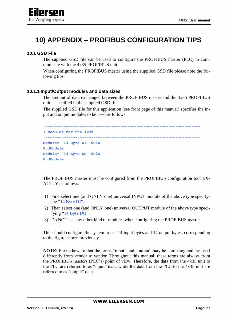
The supplied GSD file for this application (see front page of this manual) specifies the in-
put and output modules to be used as follows:
;--------------------------------------------------------------------
; Modules for the 4x35
;--------------------------------------------------------------------
Module= "14 Byte DI" 0x1D
EndModule
Module= "14 Byte DO" 0x2D
EndModule
The PROFIBUS master must be configured from the PROFIBUS configuration tool EX-
ACTLY as follows:
1) First select one (and ONLY one) universal INPUT module of the above type specify-
ing “14 Byte DI”.
2) Then select one (and ONLY one) universal OUTPUT module of the above type speci-
fying “14 Byte DO”.
3) Do NOT use any other kind of modules when configuring the PROFIBUS master.
This should configure the system to use 14 input bytes and 14 output bytes, corresponding
to the figure shown previously.
NOTE: Please beware that the terms “input” and “output” may be confusing and are used
differently from vendor to vendor. Throughout this manual, these terms are always from
the PROFIBUS masters (PLC’s) point of view. Therefore, the data from the 4x35 unit to
the PLC are referred to as “input” data, while the data from the PLC to the 4x35 unit are
referred to as “output” data.