5-1 copyright © 2008 by jose bastos chapter 5 line-frequency diode rectifiers chapter 5 diode...
TRANSCRIPT
5-1
Chapter 5
Diode Rectifiers
• Basic rectifier concepts• Single-Phase diode bridge rectifiers• Voltage-Doubler rectifiers
5-2
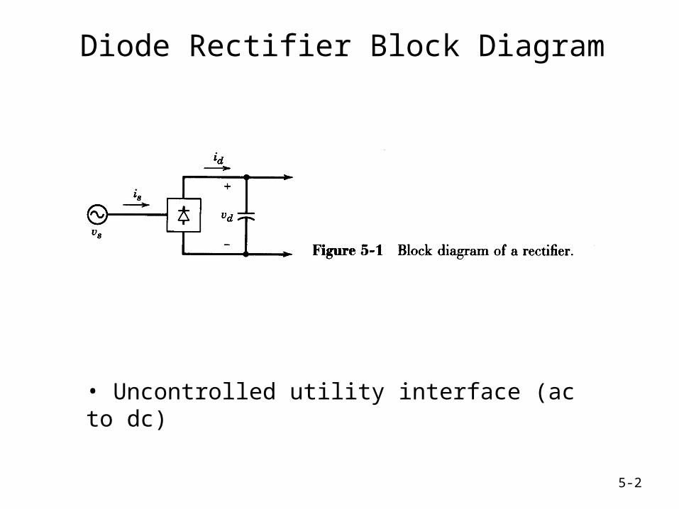
Diode Rectifier Block Diagram
• Uncontrolled utility interface (ac to dc)
5-3
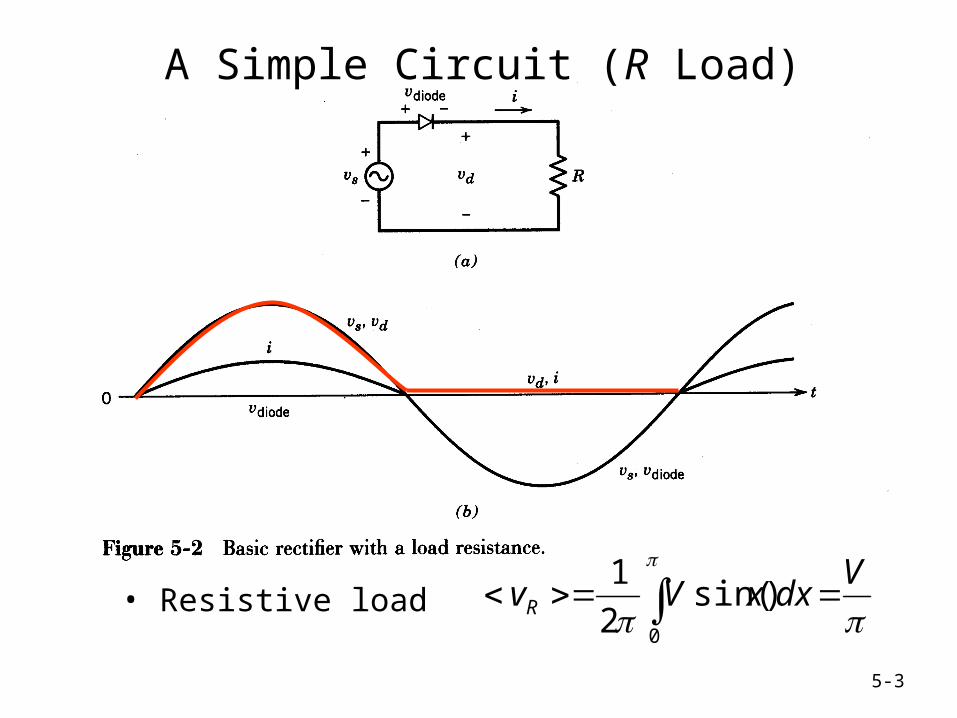
A Simple Circuit (R Load)
• Resistive load
VdxxVvR
0
)sin(2
1
5-4
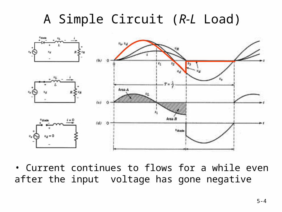
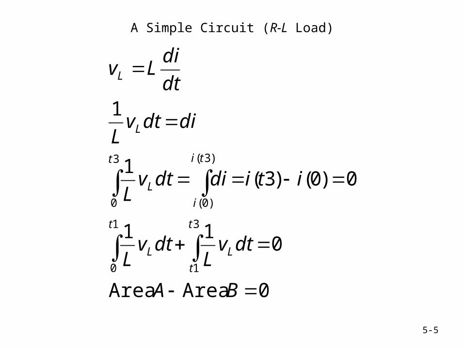
A Simple Circuit (R-L Load)
• Current continues to flows for a while even after the input voltage has gone negative
5-5
A Simple Circuit (R-L Load)
0AreaArea
011
0)0()3(1
1
3
1
1
0
3
0
)3(
)0(
BA
dtvL
dtvL
itididtvL
didtvL
dt
diLv
t
t
L
t
L
t ti
i
L
L
L
5-6
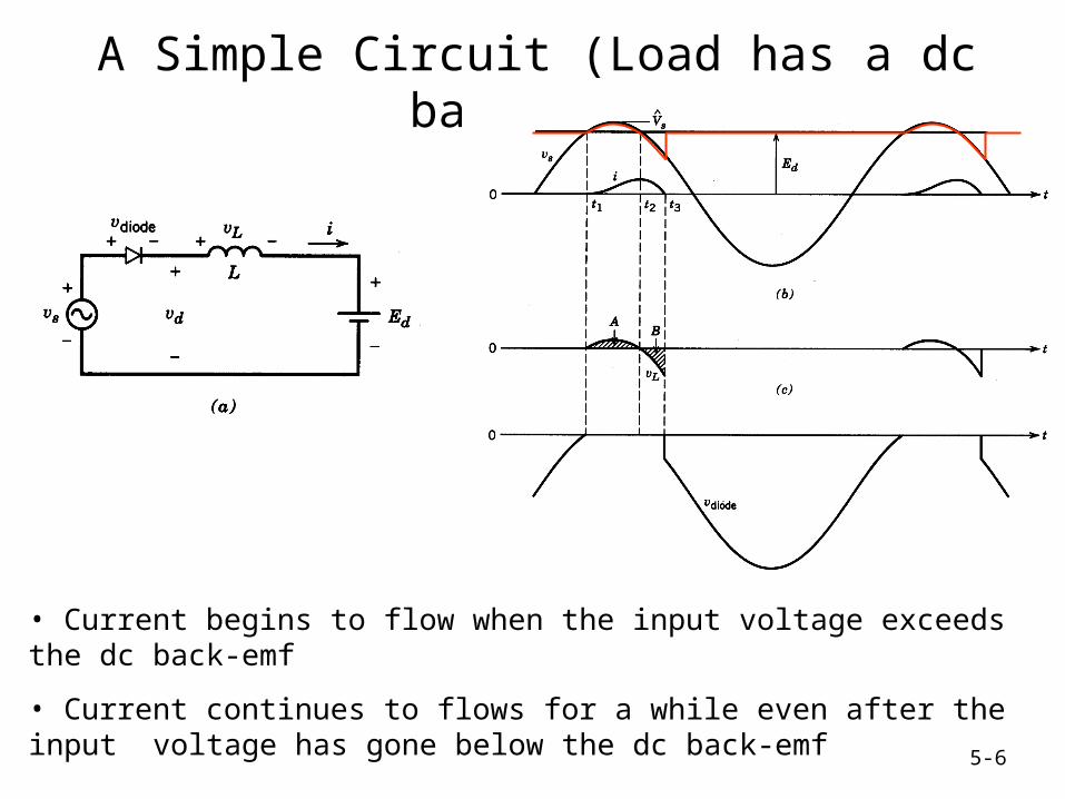
A Simple Circuit (Load has a dc back-emf)
• Current begins to flow when the input voltage exceeds the dc back-emf
• Current continues to flows for a while even after the input voltage has gone below the dc back-emf
5-7
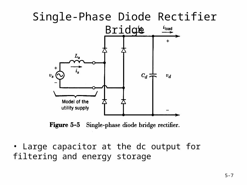
Single-Phase Diode Rectifier Bridge
• Large capacitor at the dc output for filtering and energy storage
5-8
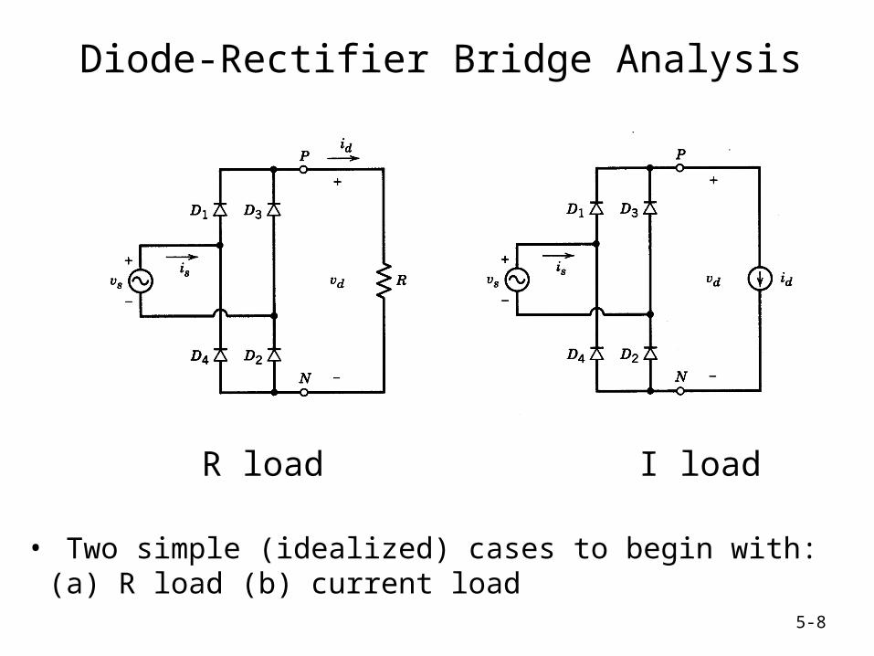
Diode-Rectifier Bridge Analysis
• Two simple (idealized) cases to begin with: (a) R load (b) current load
R load I load
5-9
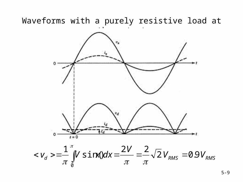
Waveforms with a purely resistive load at the output
RMSRMSd VVV
dxxVv 9.0222
)sin(1
0
5-10
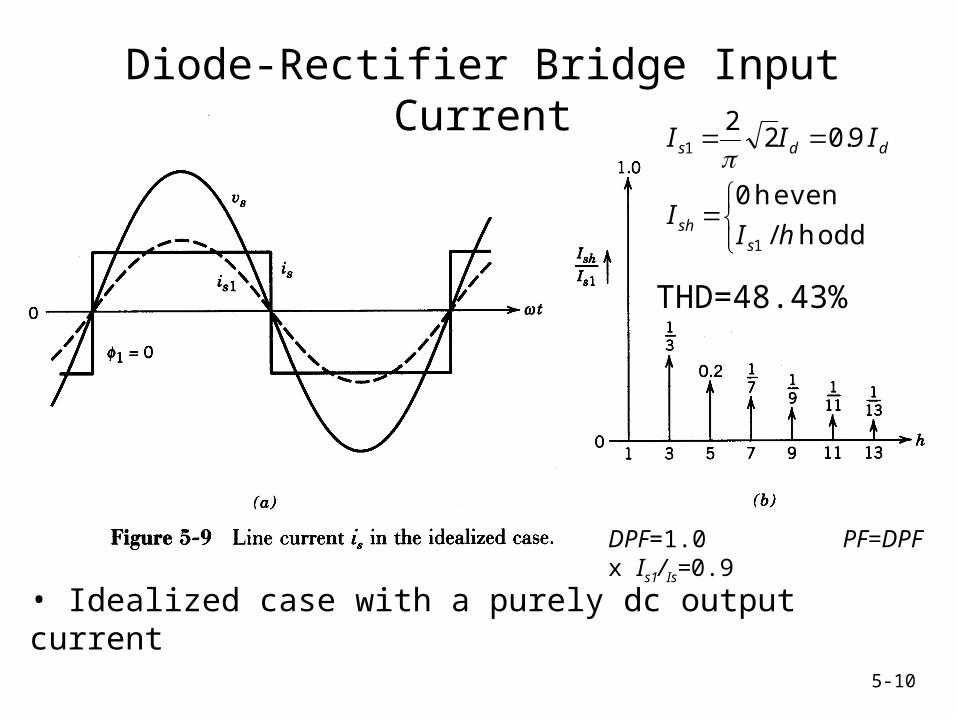
Diode-Rectifier Bridge Input Current
• Idealized case with a purely dc output current
oddh /
evenh 0
9.022
1
1
hII
III
ssh
dds
THD=48.43%
DPF=1.0 PF=DPF x Is1/Is=0.9
5-11
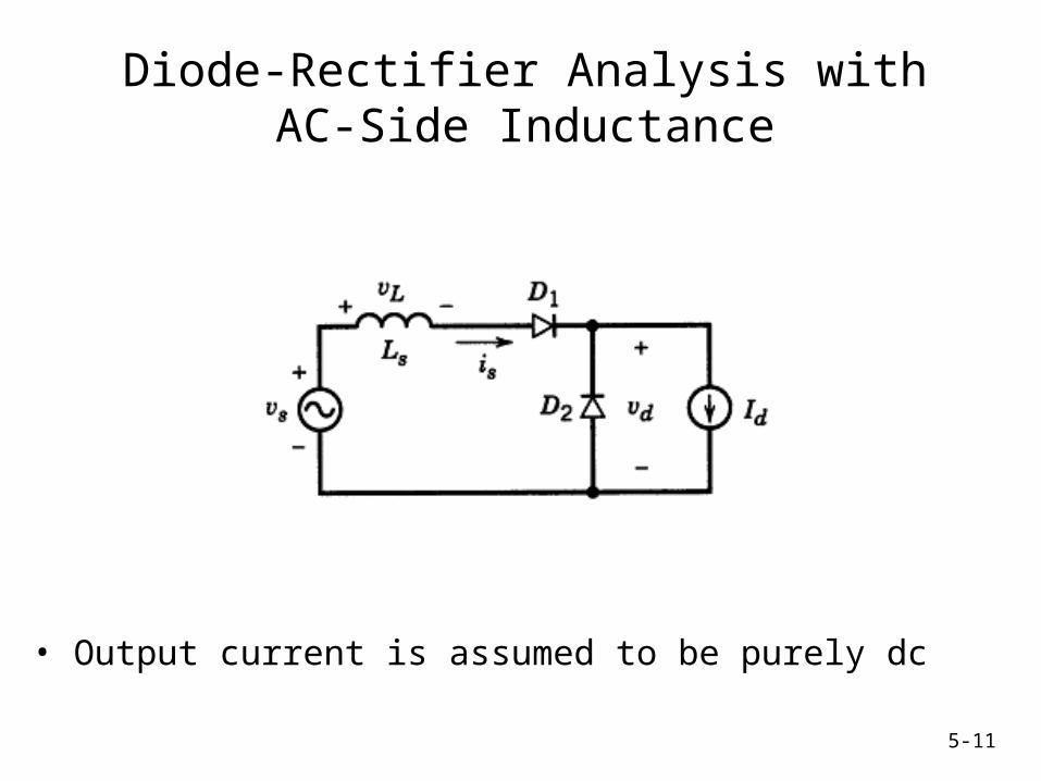
Diode-Rectifier Analysis with AC-Side Inductance
• Output current is assumed to be purely dc
5-12
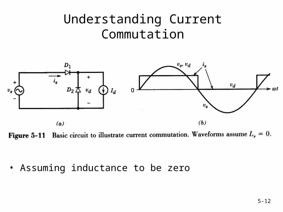
Understanding Current Commutation
• Assuming inductance to be zero

5-13
Understanding Current Commutation #2
• Assuming inductance to be zero
5-14
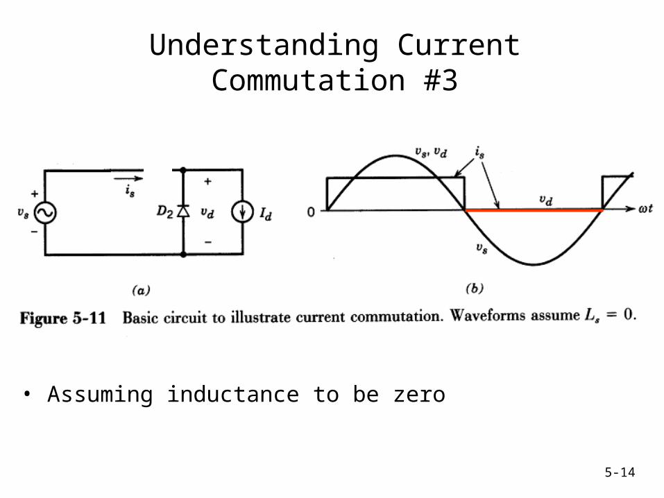
Understanding Current Commutation #3
• Assuming inductance to be zero
5-15
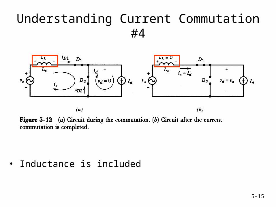
Understanding Current Commutation #4
• Inductance is included
5-16
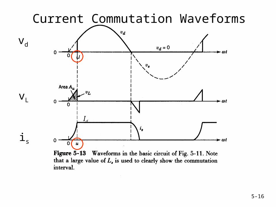
Current Commutation Waveforms
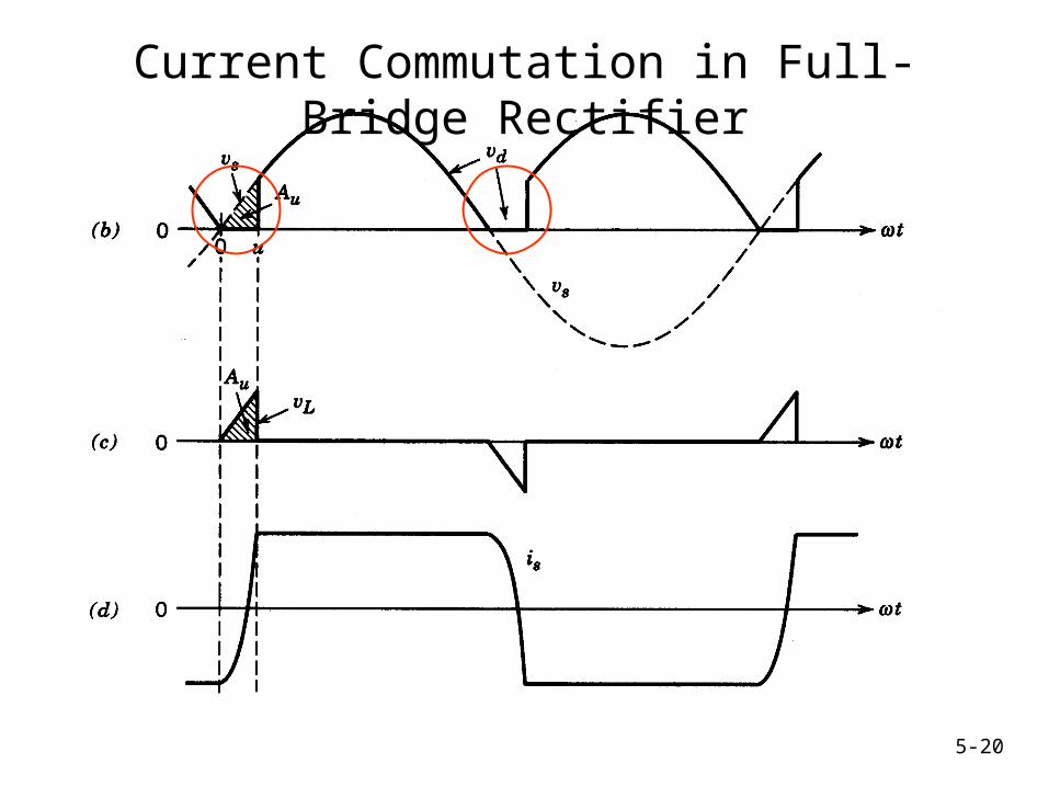
vd
vL
is
u
Id
5-17
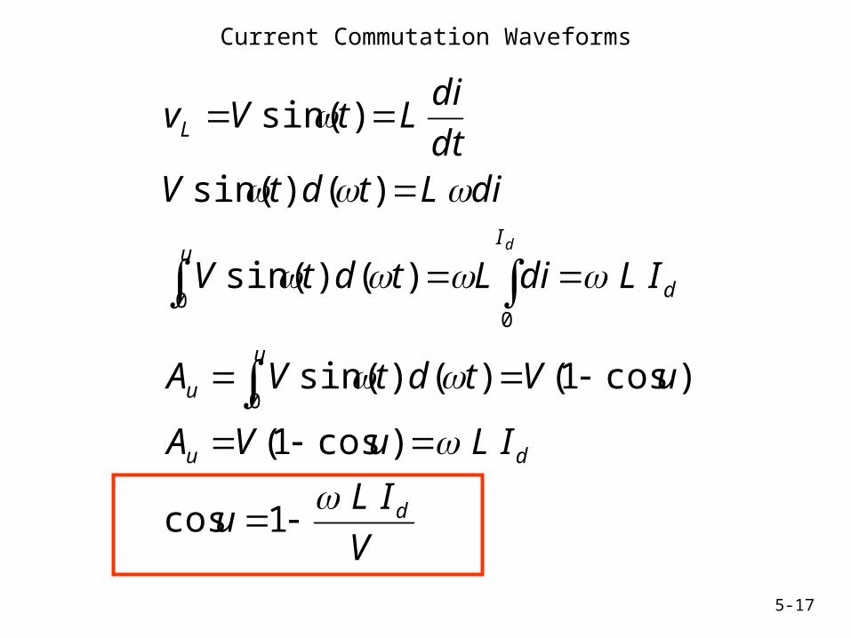
Current Commutation Waveforms
V
ILu
ILuVA
uVtdtVA
ILdiLtdtV
diLtdtVdt
diLtVv
d
du
u
u
I
d
u
L
d
1cos
)cos1(
)cos1()()sin(
)()sin(
)()sin(
)sin(
0
00

5-18
Average voltage <Vd>
dd
dRMS
u
d
RMSRMSd
IL
v
IL
V
tdtVtdtVv
VVV
tdtVv
2
245.0
)()sin(2
1)()sin(
2
1
45.021
)()sin(2
1
00
0
When L=0
With finite L
Reduction in average output voltage

5-19
Current Commutation in Full-Bridge Rectifier
5-20
Current Commutation in Full-Bridge Rectifier

5-21
Current Commutation Waveforms
V
ILu
ILuVA
uVtdtVA
ILdiLtdtV
diLtdtVdt
diLtVv
d
du
u
u
I
I
d
u
L
d
d
21cos
2)cos1(
)cos1()()sin(
2)()sin(
)()sin(
)sin(
0
0
5-22
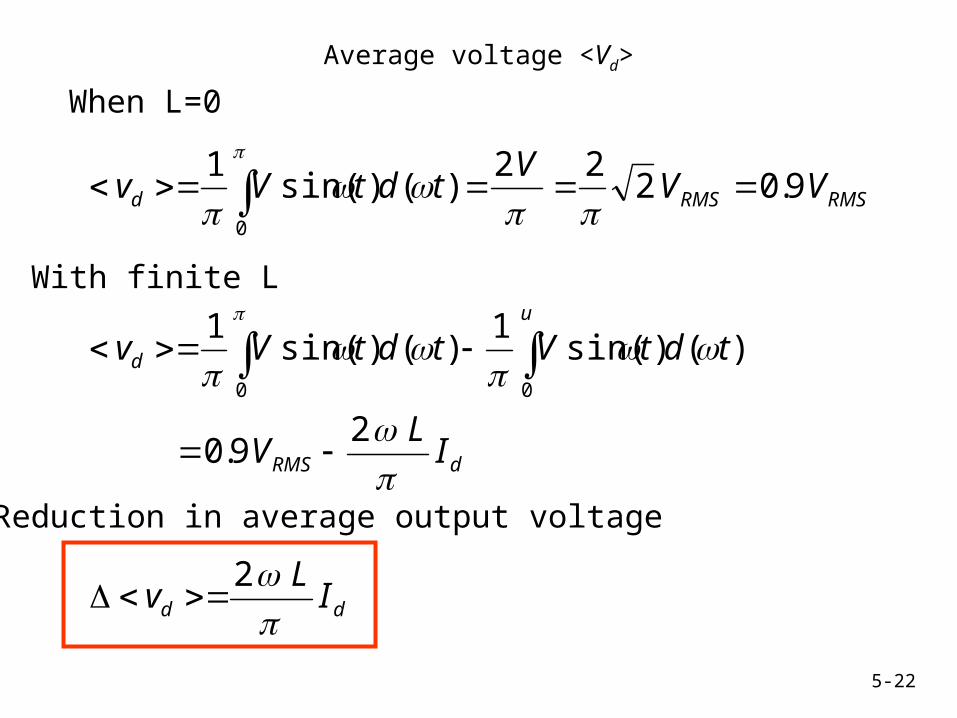
Average voltage <Vd>
dd
dRMS
u
d
RMSRMSd
IL
v
IL
V
tdtVtdtVv
VVV
tdtVv
2
29.0
)()sin(1
)()sin(1
9.0222
)()sin(1
00
0
When L=0
With finite L
Reduction in average output voltage
5-23
Conclusions
Average output voltage drops with
1. increased current
2. increased frequency
3. Increased L
Load Regulation is a major consideration in most rectifier systems because
• voltage changes with load (IL)
5-24
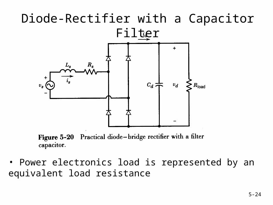
Diode-Rectifier with a Capacitor Filter
• Power electronics load is represented by an equivalent load resistance
5-25
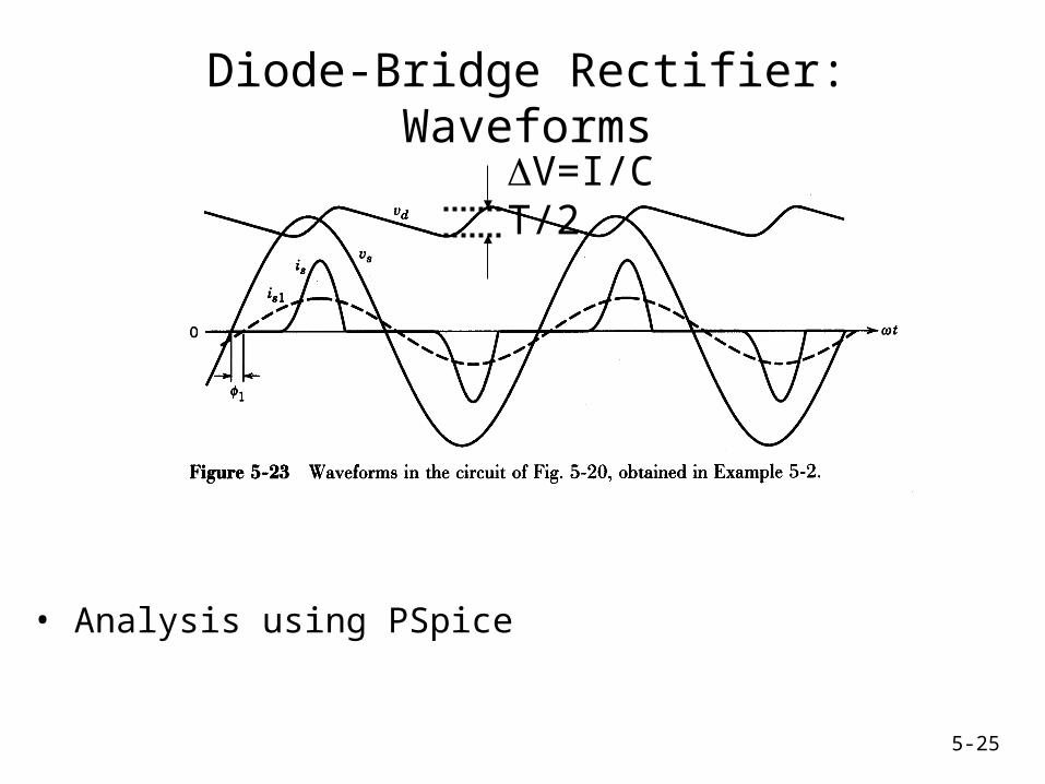
Diode-Bridge Rectifier: Waveforms
• Analysis using PSpice
V=I/C T/2
5-26
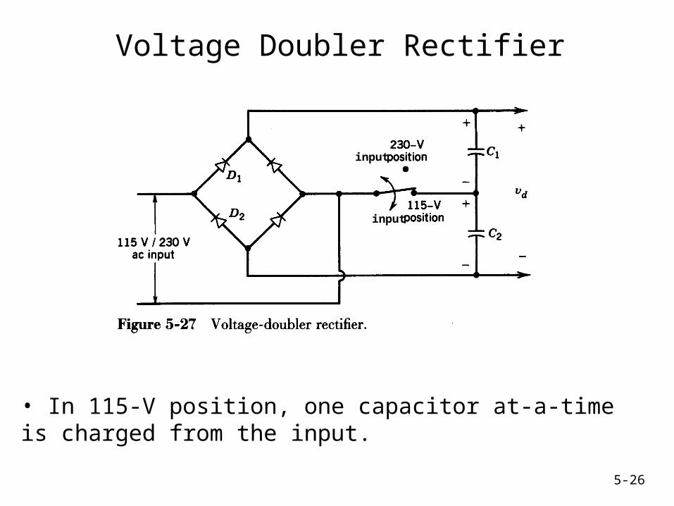
Voltage Doubler Rectifier
• In 115-V position, one capacitor at-a-time is charged from the input.
input
input