5. convective heat transfer 5.1 heat removal by coolant flow · 5.1 heat removal by coolant flow 5....
TRANSCRIPT

5.1 Heat removal by coolant flow
5. Convective Heat Transfer
Temperature at center of fuel pelletfcT
Temperature at outside surface of fuel pellet
Temperature at inside surface of fuel coolant
Temperature at outside surface of cladding tube
Coolant temperature
fT
cT
bT
mT
Fuel pellet
Bond layer
Cladding tube
Coolant flow
Heat is transferred from the surfaces of the fuel rods to the coolant.

1. Low neutron absorption cross section2. Low radiation-induced radioactivity 3. Low damage by irradiation4. High moderating power for thermal neutron
reactor, and low moderating power for fast neutron reactor
Requirement of nuclear properties
5.2 Properties of coolant
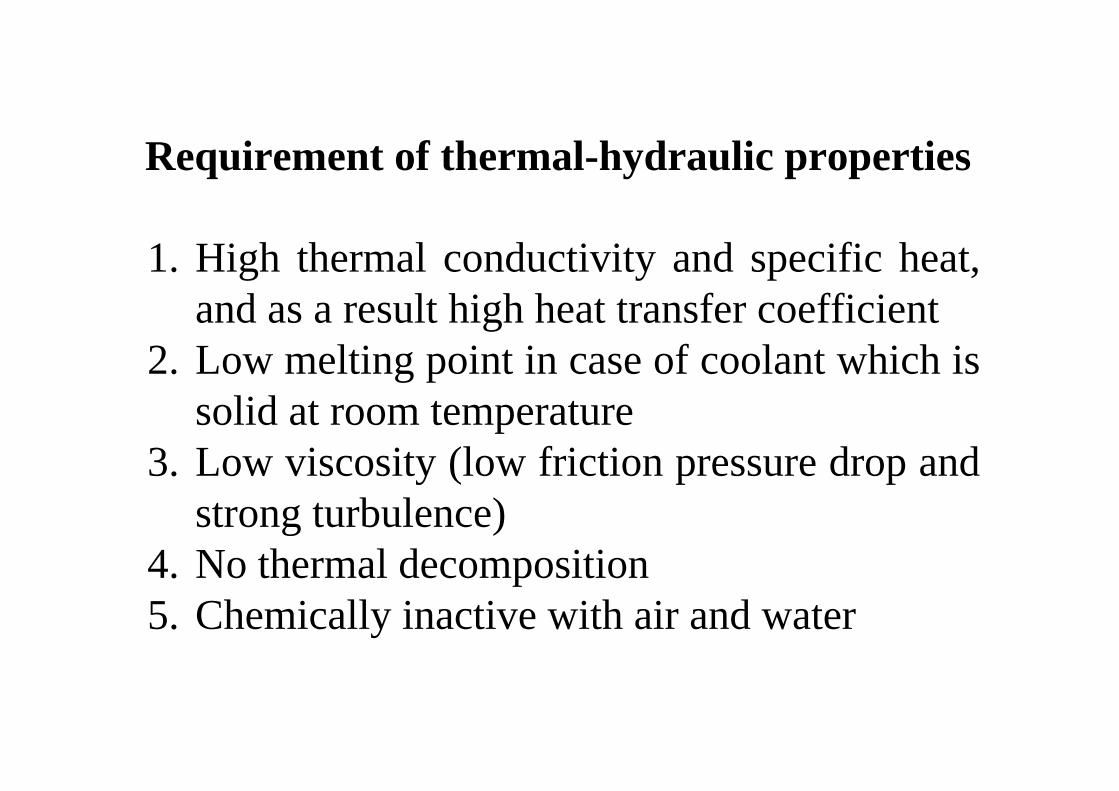
Requirement of thermal-hydraulic properties
1. High thermal conductivity and specific heat, and as a result high heat transfer coefficient
2. Low melting point in case of coolant which is solid at room temperature
3. Low viscosity (low friction pressure drop and strong turbulence)
4. No thermal decomposition5. Chemically inactive with air and water

-Low specific heat and thermal conductivity
-Required heat transfer is obtained by pressurization
Characteristics of gas coolant
Characteristics of water: light water (H2O) and heavy water (D2O)
-High pressure operation needed because of high saturation vapor pressure
-Good thermal properties-High moderating power

-Low saturation pressure (Low pressure operation is possible at high temerature)
-Low Prandtl number, high thermal conductivity, and low density
-Low corrosion rate under good control of impurity (Steel corrosion in Li is higher than in Na.)
-Chemically active with water and oxygen in case of alkali metals (Li reacts with nitrogen mildly)
Characteristics of liquid metal: alkali metals, sodium and lithium

-High specific heat (Good for heat transportation)
-High viscosity (Laminarization)-High Prandtl number (Not good for heat
transfer media)-Nickel-base alloy (Hastelloy) is compatible
with molten salt
Characteristics of molten salts:Flibe (LiF-BeF2), HTS (NaNO3-KNO3-NaNO2), Flinak(LiF-NaF-KF), Li2CO3-Na2CO3-K2CO3, etc.
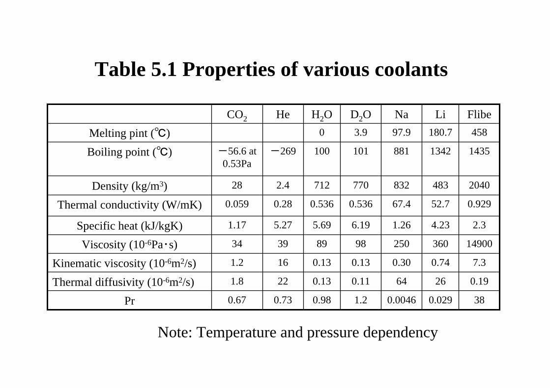
0.19 26640.110.13 221.8Thermal diffusivity (10-6m2/s)
2.34.231.266.195.695.271.17Specific heat (kJ/kgK) 1490036025098 89 3934Viscosity (10-6Pa・s)
7.30.740.300.130.13161.2Kinematic viscosity (10-6m2/s)
380.0290.00461.20.980.73 0.67Pr
0.92952.767.40.5360.5360.280.059Thermal conductivity (W/mK)
20404838327707122.428Density (kg/m3)
14351342881101100-269 -56.6 at 0.53Pa
Boiling point (℃)
458 180.7 97.9 3.9 0 Melting pint (℃) FlibeLi NaD2O H2O He CO2
Table 5.1 Properties of various coolants
Note: Temperature and pressure dependency

5.3 Approach to convective heat transfer (Single-phase flow)
Solid
Velocity v
Temperature T
Coolant flow
Heat flux q”
How to calculate the heat transfer coefficient, or the temperature profile close to the solid surface, i. e. the fuel rod surfaces in coolant?
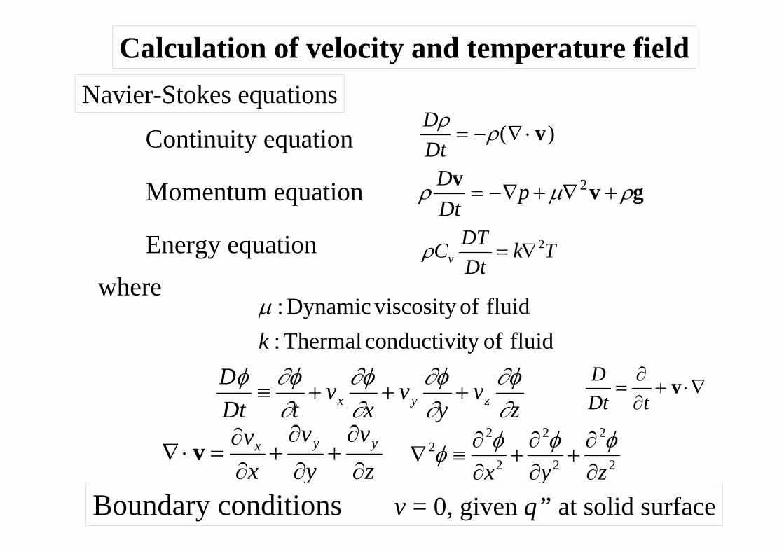
Continuity equation
TkDtDTCv
2∇=ρ
ρ μ ρDDt
pv v g= −∇ + ∇ +2
DDtρ ρ= − ∇ ⋅( )v
zv
yv
xv
tDtD
zyx ∂∂φ
∂∂φ
∂∂φ
∂∂φφ
+++≡
zv
yv
xv yyx
∂
∂+
∂
∂+
∂∂
=⋅∇ v2
2
2
2
2
22
zyx ∂∂
+∂∂
+∂∂
≡∇φφφφ
Momentum equation
Energy equationwhere
Navier-Stokes equations
Boundary conditions v = 0, given q” at solid surface
fluid ofty conductivi Thermal: fluid of viscosityDynamic :
kμ
Calculation of velocity and temperature field
∇⋅+∂∂
= vtDt
D

' ,' ,' wwwvvvuuu +=+=+=
yu
yuvu MT ∂
∂ρε∂∂μρτ ==−= ''
Eddy diffusivity of momentum
ylength Mixing
,2
κ∂∂ρμ
=
=
m
mT
lyul
⎪⎭
⎪⎬⎫
⎪⎩
⎪⎨⎧
−⎟⎟⎠
⎞⎜⎜⎝
⎛
∂∂
+∂∂
∂∂
+∂∂
−= jii
j
j
i
ji
i vvxv
xv
xxP
DtvD ''1 ν
ρ
Reynolds equation (Time average)
Average velocity and fluctuation
Prandtl’s mixing length model
Reynolds stress (additional terms)
Mε
Approach to turbulent flow
Time t
u’
u
Turbulence model
41.0=κ
Nikuladse)(by flow pipein ,106.0108.014.042
⎟⎠⎞
⎜⎝⎛ −−⎟
⎠⎞
⎜⎝⎛ −−=
Ry
Ry
Rlm
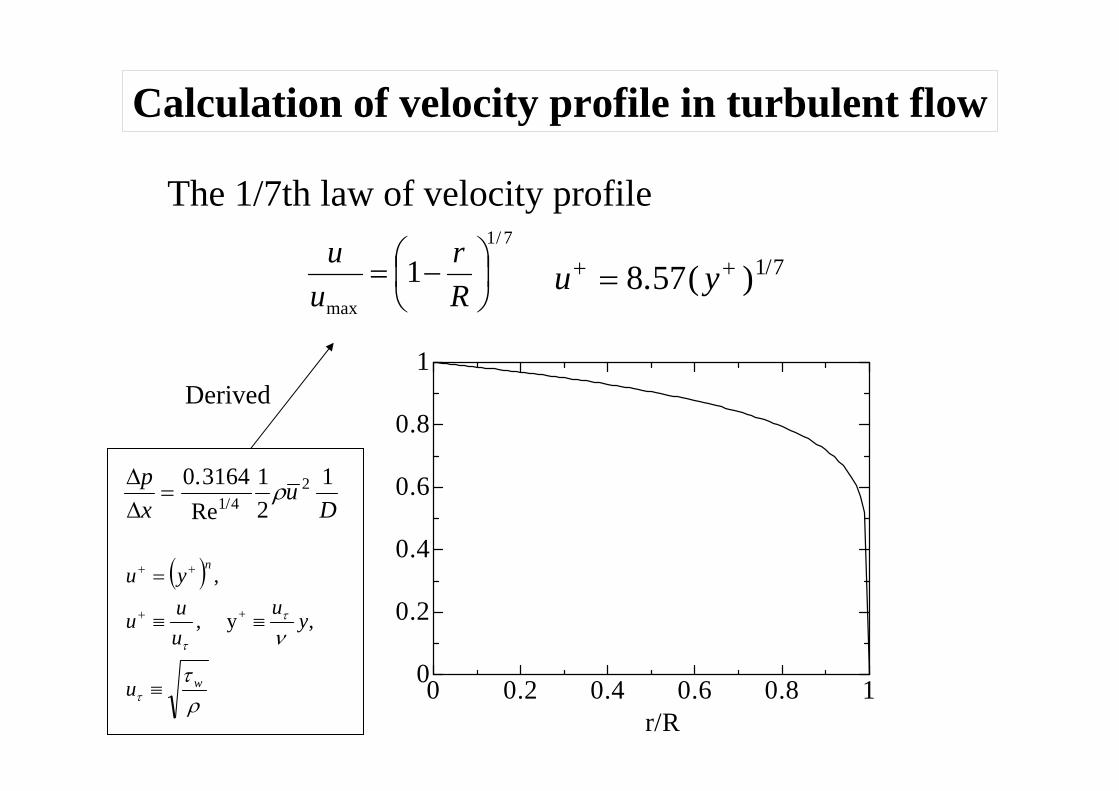
u y+ += 8 57 1 7. ( ) /7/1
max
1 ⎟⎠⎞
⎜⎝⎛ −=
Rr
uu
The 1/7th law of velocity profile
Calculation of velocity profile in turbulent flow
0 0.2 0.4 0.6 0.8 10
0.2
0.4
0.6
0.8
1
r/R
ΔΔ
px
uD
=0 3164 1
21
1 42.
Re / ρ
( )
ρτ
ν
τ
τ
τ
w
n
u
yu
uuu
yu
≡
≡≡
=
+
++
,y ,
,
+
Derived

100 101 102 1030
5
10
15
20
25
u+
y+
u+=5.5+2.5ln(y+)
u+=5.0+5.0ln(y+/5)
u+=y+
5 30
+
+
=
<<
yy
+u ,50
)5/ln(0.50.5u ,305
+ +
+
+=
<<
yy
)ln(5.25.5u ,30
+ +
+
+=
<
yy
wwu
yvuuuu
τρττ
ττ
stressshear Wall,/ elocity Friction v
,)/(y ,/ velocity ldimensiona-Non +
≡
≡≡+
von Karman’s universal velocity profile (Log law)Viscous sublayer
Transition region
Turbulence region
where
Derived from Prandtl’s mixing length model

LES:Large eddy simulationDNS: Direct numerical simulation
Empirical heat transfer correlations
Approximation of Boundary layer
Navier-Stokes equations
Mixing length model
・Two equation model・Reynolds stress model
・LES・DNS
Solid (Fuel rod)Heat conduction
Fluid (Coolant)
Experiment
Turbulence models
Theoretical heat transfer equations
Various approach
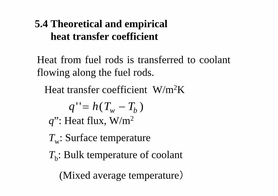
Heat from fuel rods is transferred to coolant flowing along the fuel rods.
q h T Tw b' ' ( )= −q”: Heat flux, W/m2
Tw: Surface temperatureTb: Bulk temperature of coolant
(Mixed average temperature)
Heat transfer coefficient W/m2K
5.4 Theoretical and empirical heat transfer coefficient

5.4.1 Measurement of heat transfer coefficient
DLqTTDuc inoutp ππρ '')(4
2=−
Heat balance
Smooth channel with uniform heat flux or uniform wall temperature
Hydro-dynamically and thermally fully developed flow
''qU niform heat flux
uFluid
δ
inT outT
L
D

Determination of heat transfer coefficient
2/)(''
outinw TTTqh+−
=
Heat flux q’’determined from input power,
radial temperature gradient in channel wall, andenthalpy increase from inlet to outlet: temperature
difference and flow rate Inner surface temperature Tw
determined from extrapolation of radial temperature gradient in channel wall
Fluid temperature (Tin+Tout)/2

Reynolds number:Ratio of inertia term to diffusion term in momentum equation
5.4.2 Non-dimensional correlations
Hydraulic diameter: Characteristic length of flow channel
D AFe ≡
4
Nu hDk
≡
Re ≡ =ρμ νuD uD
Pr ≡ =c
kpμ ν
α
Prandtl number:Ratio of velocity boundary layer thickness to temperature one
Nusselt number:Non-dimensional heat transfer coefficient

Empirical heat transfer correlations
Laminar flow -Heated plate-Constant heat flux
3/12/1 PrRe916.0=Nu
5.0Pr >
Turbulent flow (Dittus-Boelter’s equation)-Uniform wall surface temperature
nNu PrRe023.0 8.0=
3.0Cooling4.0Heating
==
nn
510Re > 60/ >DL100Pr7.0 <<

Liquid metal flow (Subbotin’s equation)
8.0025.05 PeNu +=
1.0Pr <510PrRe >≡Pe
Length of entrance region
[ ] 275.08.02.0 )//(Re11.1 / DLNuNum =∞
4/1Re623.0/ =DL
In case of undeveloped thermal boundary layer

Nu=0.916Re1/2Pr1/3Pr>0.5Constant q”
AvarageNu=0.664Re1/2Pr1/3Pr>0.6Constant TwPlateNu=3.65Constant Tw
Fully developed
Nu=4.36Constant q”Pipe
CommemtsCorrelation
kLhNu /≡
Table 5.2 Heat transfer correlation for forced convective laminar flow

Num/Nu0=1.11[Re0.2/(L/D)]0.275
Nu=5+0.025Pe0.8
Nu=0.023Rex0.8Prn
Nu=0.0288Rex0.8Pr1/3
Correlation
Pipe
Plate
Undeveloped, Entrance length L/D=0.623Re1/4
Developed, Subbotin’s equatin
0.1>PrPe=RePr>105
Constant q”
Developed, Dittus-Boelter’s equationn=0.4 for heatingn=0.3 for cooling
0.7<Pr<100Re>105
L/D>60
Constant Tw
Developed, LocalNux=hxx/k
CommentsConditions
Table 5.3 Heat transfer correlation for forced convective turbulent flow

102 103 104 105100
101
102
Reynolds number Re
Nus
selt
num
ber
Nu Nu=0.023Re0.8Pr0.4
(Turbulent flow, Dittus-Boelter)
Nu=5+0.025Re0.8Pr0.8
(Turbulent flow, Subbotin, Liquid metal)
Nu=4.36 (Laminar, q'':Const.)
Nu=3.65(Laminar flow, T:Const)

5.4.3 Check points for use of heat transfer correlations
- Experimental conditions in derivation of the correlation
- Applicability range in Re and Pr- Laminar flow or turbulent flow?- Fully developed or undeveloped?- Constant wall temperature or constant heat
flux?- Definition of characteristic length such as
hydraulic diameter
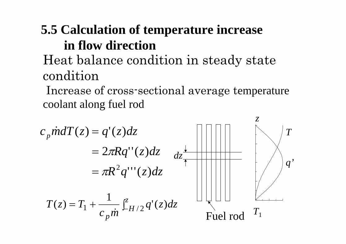
5.5 Calculation of temperature increasein flow direction
Heat balance condition in steady state conditionIncrease of cross-sectional average temperature
coolant along fuel rod
dzzqR
dzzRq
dzzqzdTmcp
)('''
)(''2
)(')(
2π
π
=
=
=&
∫+= −zH
pdzzq
mcTzT 2/1 )('1)(
&
z
dz
T1Fuel rod
q’
T

Prandtl’s boundary layer theory for laminar flow
2
2
yu
dxdpg
yuv
xuu c
∂∂ν
ρ∂∂
∂∂
+−=+
Momentum equation in x-direction
5.6 Calculation of Pressure drop in fuel bundle
0=+yv
xu
∂∂
∂∂dp
dy= 0
Boundary layer approximation
x
yu
Basic theory for friction shear stress
Continuity equation
∞V
sτ
L
Lff dxc
LC
Re328.11
0 =∫≡2/2∞∞
≡V
c sf
ρτ
2
2uc fwρτ =
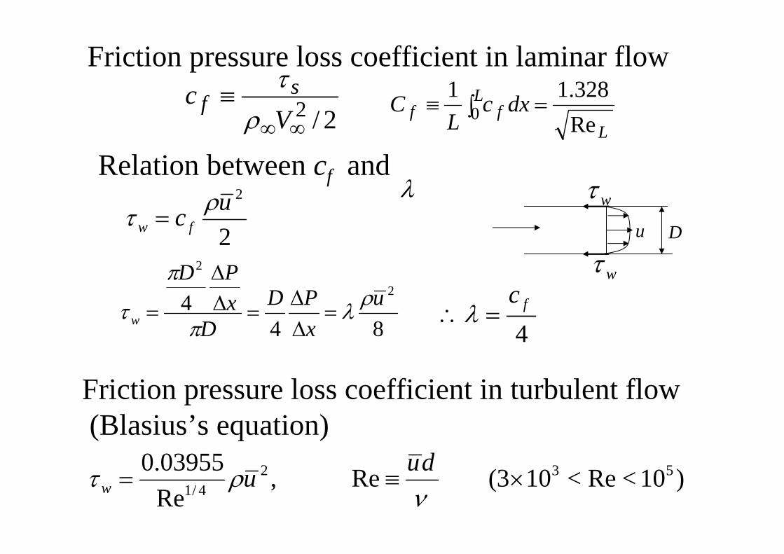
Friction pressure loss coefficient in laminar flow
844
2
2
uxPD
DxPD
wρλ
π
π
τ =ΔΔ
=ΔΔ
=
Relation between cf and λ
4fc
=∴λ
wτ
wτDu
)10<Re<103( Re ,Re03955.0 532
4/1 ×≡=ν
ρτ duuw
Friction pressure loss coefficient in turbulent flow(Blasius’s equation)
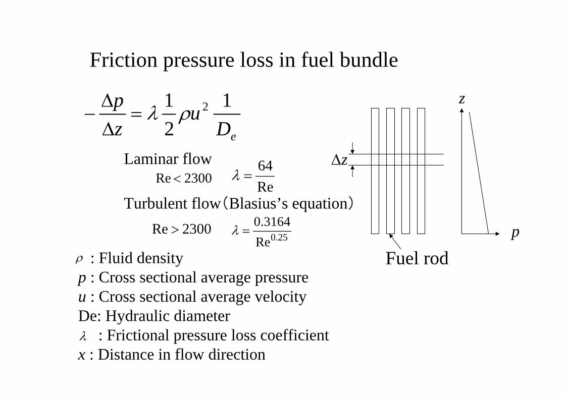
: Fluid density p : Cross sectional average pressureu : Cross sectional average velocityDe: Hydraulic diameter
: Frictional pressure loss coefficientx : Distance in flow direction
eDu
zp 1
21 2ρλ=
ΔΔ
−
Friction pressure loss in fuel bundle
ρ
λ
z
Fuel rodp
zΔ
Re64
=λ
25.0Re3164.0
=λ2300Re >
2300Re <Laminar flow
Turbulent flow(Blasius’s equation)
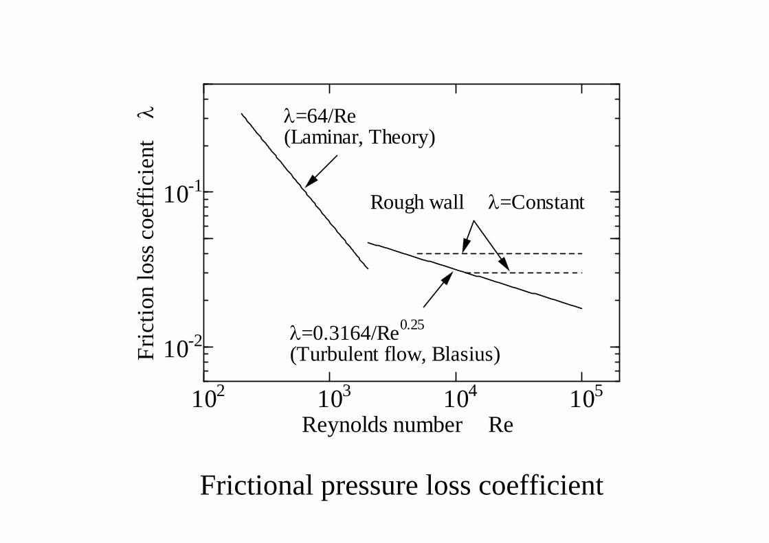
Frictional pressure loss coefficient
102 103 104 105
10-2
10-1
Reynolds number Re
Fric
tion
loss
coe
ffic
ient λ
λ=0.3164/Re0.25
(Turbulent flow, Blasius)
λ=64/Re(Laminar, Theory)
Rough wall λ=Constant

Pressure loss in various channel geometries
2
21 u
zp ρξ=
ΔΔ
For grid spacer, orifice, venturi, elbow, etc.
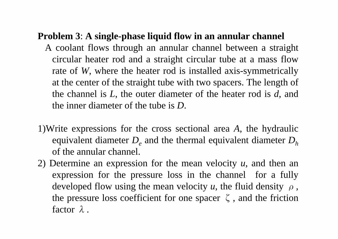
Problem 3: A single-phase liquid flow in an annular channelA coolant flows through an annular channel between a straight
circular heater rod and a straight circular tube at a mass flow rate of W, where the heater rod is installed axis-symmetrically at the center of the straight tube with two spacers. The length of the channel is L, the outer diameter of the heater rod is d, and the inner diameter of the tube is D.
1)Write expressions for the cross sectional area A, the hydraulic equivalent diameter De and the thermal equivalent diameter Dh of the annular channel.
2) Determine an expression for the mean velocity u, and then an expression for the pressure loss in the channel for a fully developed flow using the mean velocity u, the fluid density ρ, the pressure loss coefficient for one spacer ζ, and the friction factor λ.
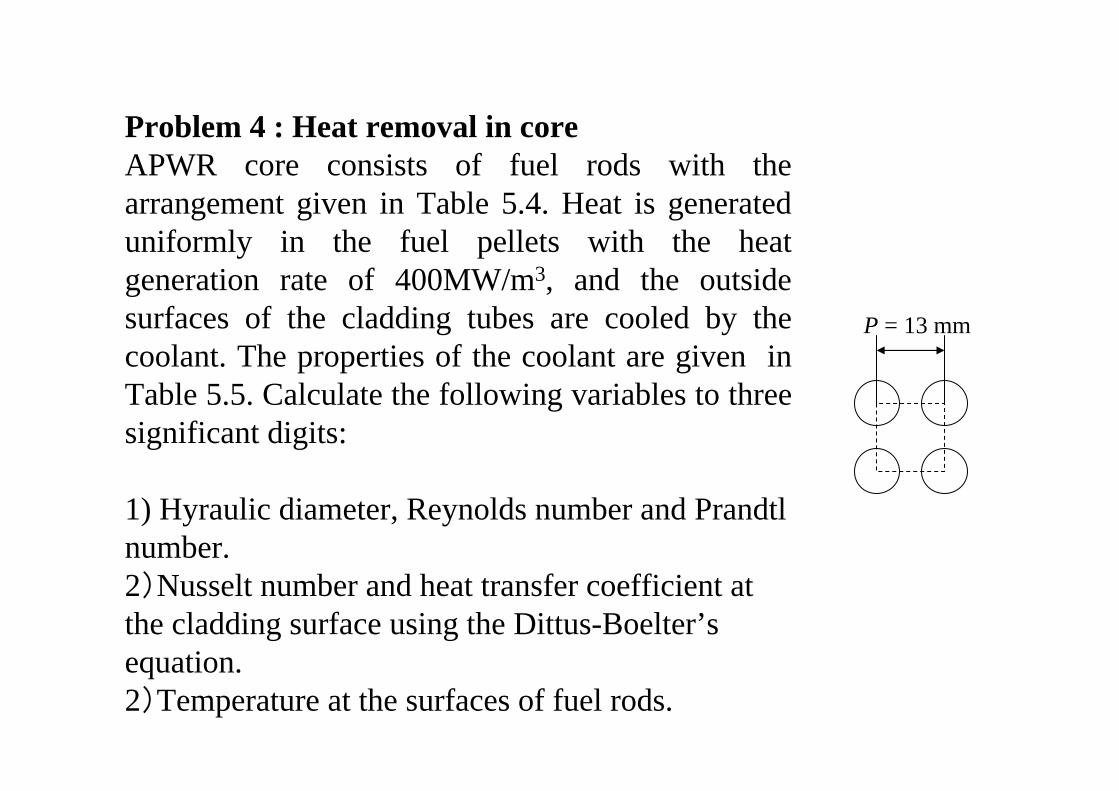
Problem 4 : Heat removal in coreAPWR core consists of fuel rods with the arrangement given in Table 5.4. Heat is generated uniformly in the fuel pellets with the heat generation rate of 400MW/m3, and the outside surfaces of the cladding tubes are cooled by the coolant. The properties of the coolant are given in Table 5.5. Calculate the following variables to three significant digits:
1) Hyraulic diameter, Reynolds number and Prandtlnumber.2)Nusselt number and heat transfer coefficient at the cladding surface using the Dittus-Boelter’sequation.2)Temperature at the surfaces of fuel rods.
P = 13 mm
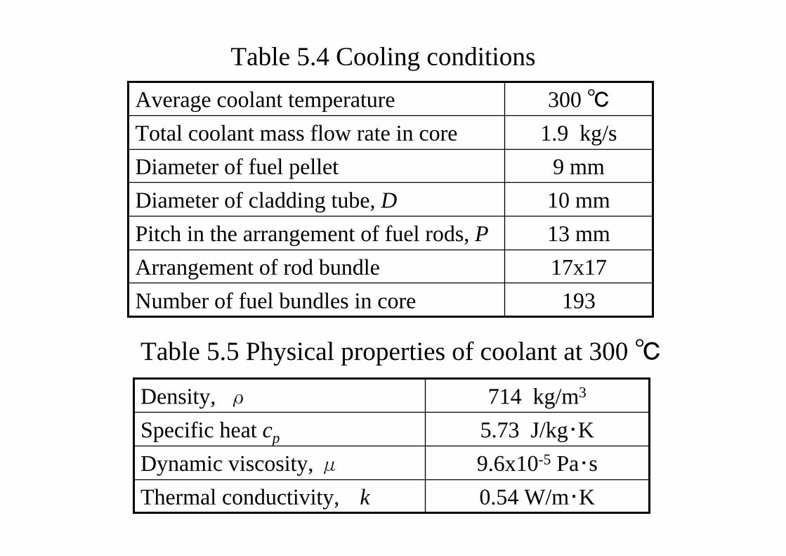
9 mmDiameter of fuel pellet10 mmDiameter of cladding tube, D
193 Number of fuel bundles in core 17x17 Arrangement of rod bundle 13 mm Pitch in the arrangement of fuel rods, P
1.9 kg/s Total coolant mass flow rate in core 300 ℃Average coolant temperature
Table 5.4 Cooling conditions
0.54 W/m・K Thermal conductivity, k9.6x10-5 Pa・s Dynamic viscosity, μ5.73 J/kg・K Specific heat cp
714 kg/m3Density, ρ
Table 5.5 Physical properties of coolant at 300 ℃