5. electric starter - coodie.com crf110f service repair manual... · 5. electric starter starter...
TRANSCRIPT

COMPONENT LOCATlON ········ ··· ··· ···· ····· ··· ··5·2
SYSTEM DIAGRAM ··· ·· ···· ··························· ··5·2
SERVICE INFORMATION ······ ·· ·····················5·3
TROUBLESHOOTlNG····· ··· ·· ··· ··· ·· ···· ········ ·····54
5. ELECTRIC STARTER
STARTER MOTOR ................ ....................... 5·6
STARTER RELAY ································· ··· ···· · 5·9
STARTER SWITCH·········· ··· ················ ······ .. 5·10
NEUTRAL SWITCH ······· ···· ······ ··················· 5·11
5-1

ELECTRIC STARTER
COMPONENT LOCATION STARTER SWITCH
STARTER MOTOR IGNITION SWITCH
BATIERY
SWITCH STARTER RELAY
SYSTEM DIAGRAM FUSE 10 A
R ---<Q.rO~-- RlBI ------,Vr---RlBI
BI
5·2
R
BATTERY
BI • RIW
STARTER MOTOR
STARTER RELAY
REGULA TORI RECTIFIER
L9/R ---f03 I NEUTRAL SWITCH
Y/RflSI
STARTER SWITCH
ENGINE STOP SWITCH
1 BWW
BI: Black
Y: Yellow
Bu: Blue
R: Red
W:While Lg: light green
IGNITION SWITCH
•

SERVICE INFORMATION GENERAL
I NOTICE
ELECTRIC STARTER
If the current is kept flowing through the starter motor to tum it while the engine is not cranking Oller, the starter motor may be damaged,
When checking the starter system, always follow the steps in the troubleshooting (page 5-4). The starter motor can be serviced with the engine in the frame. Always tum the ignition switch to OFF before servicing the starter motor. The motor could suddenly start, causing serious injury. Refer to procedure for starter clutch servicing (page 11 -5). Refer to information for ignition switch (page 4-9). Refer to inspection for engine stop switch (page 4-10).
SPECIFICATION
ITEM Starter motor brush length
TORQUE VALUE
ITEM Q'TY
Starter motor cable screw 1
STANDARD 7.0 (0.28)
THREAD TORQUE DIA. fmml N"m l kgf'm, IbHtl
4 2 (0.2,1.5)
Unit: mm (in) SERVICE LIMIT 3.5 (0. 14)
REMARKS
5-3

ELECTRIC STARTER
TROUBLESHOOTING
5-4
Starter motor does not turn
1. Fuse Inspection
Check for blown fuse (10 A).
Is the fu se blown?
YES - Replace the fuse.
NO - GO TO STEP 2.
2. BaHery Inspection
Make SUfe the battery is fully charged and in good condition.
Is the battery in good condition?
YES - GO TO STEP 3.
NO - Charge or replace the battery.
3. Battery Cable Inspection
Check the battery cables for loose or poorly connected terminal, and for an open circuit.
/s the battery cable in good condition?
YES - GO TO STEP 4.
NO -' Loose or poorly connected battery cables. • Open circuit in the battery cable.
4. Starter Motor Cable Inspection
Check the starter motor cable for loose or poorly connected terminal, and for an open circuit.
Is the terminal loose or poorly connected?
YES -' Loose or poorly connected starter motor cable. • Open circuit in the starter motor cable.
NO - GO TO STEP 5.
5. Starter Relay Operation Inspection
Check the operation of the starter relay (page 5¥9).
Does the starter relay click?
YES - GO TO STEP 6.
NO - GO TO STEP 7.
6. Starter Motor Inspection
Connect the starter motor terminal to the battery positive terminal directly. (A large amount of current flows, so do not use a thin wire.)
Does the starter motor turn?
YES - Faulty starter relay.
NO - Faulty starter motor.
7. Relay Coil Ground Une Inspection
Check the ground line of the starter relay (page 5--10).
Is the ground line normal?
YES - GO TO STEP 8.
ND Faulty neutral switch (page 5--11). Loose or poor contact of the related connector terminal. Open circuit in Light greenfred wire between the starter relay and neutral switch.
•
•
•
•

ELECTRIC STARTER 8. Relay Coil Power Input Line Inspection
Check the power input line of the starter relay (page 5-10).
Is the power input line normal?
YES - GO TO STEP 9.
NO Faulty ignition switch. Faulty engine stop switch. Faulty starter switch . Loose or poor contact of the related connector terminal. Open circui t in Yellowfred wire between the starter relay and starter switch . Open circui t in Black wire between the starter switch and engine slop switch . Open circuit in Bluefwhite between the engine stop switch and ignition switch.
9. Starter Relay Inspection
-- Check the function of the starter relay (page 5-10).
Does the starier relay function properly?
YES - loose or poor contact of the starter relay connector.
NO - Faulty starter relay,
Starter motor turns engine slowly Low baltery voltage Poorly connected battery cable Poorly connected starter motor cable Faulty starter motor Poorly connected ground cable terminal
Starter motor turns, but engine does not turn • Faulty slaner clutch • Damaged starler gear train
Starter relay clicks, but engine does not turn over • Crankshaft does nol turn due to engine problems
5·5
ELECTRIC STARTER
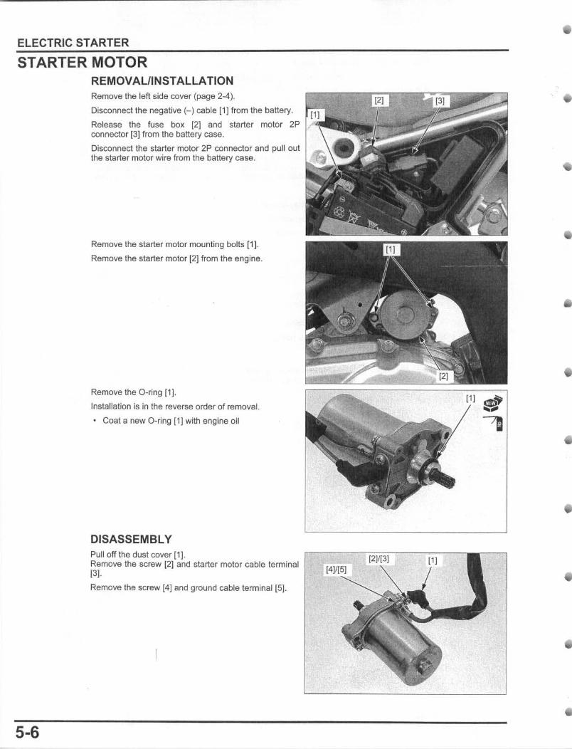
STARTER MOTOR REMOVAUINSTALLATION Remove the left side cover (page 2-4).
5·6
Disconnect the negative H cable {1} from the battery.
Release the fuse box [21 and starter motor 2P connector (3] from the battery case.
Disconnect the starter motor 2P connector and pull out the starter motor wire from the battery case.
Remove the starter motor mounting bolts (1 J.
Remove the starter motor (2] from the engine.
Remove the O-ring [1 J. Installation is in the reverse order of removal.
• Coat a new D-ring [1 ) with engine oil
DISASSEMBLY Pull off the dust cover [1}. Remove the screw [2] and starter motor cable terminal 131· Remove the screw [4] and ground cable terminal IS].
The armatufB is magnetically
attrac/ad to the
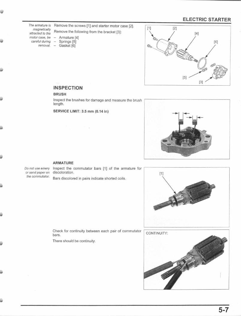
Remove the screws [1J and starter molor case [2J.
Remove the following from the bracket [31: 12]
ELECTRIC STARTER
14] motor case, be - Armature [4J careful during - Springs [5]
removal. - Gasket [6] 16]
Do not use emery or sand paper on the commutator.
INSPECTION BRUSH
Inspect the bruslles for damage and measure the brush , ------ --- ----------, length.
SERVICE LIMIT: 3.5 mm (0.14 in)
ARMATURE Inspect the commutator bars [1) of the armature for ,-----------------discoloration . 11 Bars discolored in pairs indicate shorted coils.
Check for continuity between each pair of commutator ;::C=O=N=T='N=U='=TY=' ============~ bars.
There should be continuity.
5-7

ELECTRIC STARTER
Check for continuity between each commutator bar and the armature shaft.
There should be no continuity.
ASSEMBLY Install the springs [1] in the brush holders 12J.
NO CONTINUITY:
[21
Install the armature (1) into the bracket while holding the ::;;;;;;;;;;;::;;;;::::;;;:::=========~ brushes (2] .
Install a new gasket [1J onto the bracket [2). The armalUfB /S Install the bracket and armature 13] to the motor case
magnetically (4] while holding the bracket side armature shaft tlghUy. attracted to the motorCSS8, be car&fui during
instaHstion.
5-8
[11

ELECTRIC STARTER Install and tighten the motor case screws [lJ .
Install the ground cable terminal [1] and tighten the ~=====;;:;;;::;====.:::::==;_=~ screw [2J.
Install the starter motor cable terminal (3] and tighten the screw [4] to the specified torque.
TORQUE: 2 N'm (0.2 kgf 'm, 1.5IbHt)
Put back the dust cover [5] in the appropriate position.
STARTER RELAY REMOVAL/INSTALLATION Remove the left side cover (page 2-4).
Release the starer relay [lJ from the battery case and Disconnect the starter relay 5P connector [2].
OPERATION INSPECTION Remove the left side cover (page 2-4).
Shift the transmission into neutra!. Turn the ignition switch to ON and engine stop switch to .0", push the starter switch . The coil is normal if the starter relay [1] clicks.
If you don't hear the click, inspect the starter relay circuits (page 5-10).
5-9
ELECTRIC STARTER
CIRCUIT INSPECTION GROUND LINE
Remove the left side cover (page 2-4).
Disconnect the starter relay 5P connector 11).
Check for continuity between the Light green/red wire terminal of the wire harness side connector and ground .
If there is continuity when the transmission is in neutral, the ground circuit is normal.
POWER INPUT LINE
Connect the starter relay 5P connector.
Tum the ignition switch to ON and engine stop switch to orr. Measure the voltage between the Yellow/red wire terminal (+) and ground (-).
If batter)' voltage appears only when the starter switch Is pushed, the circuit is normal.
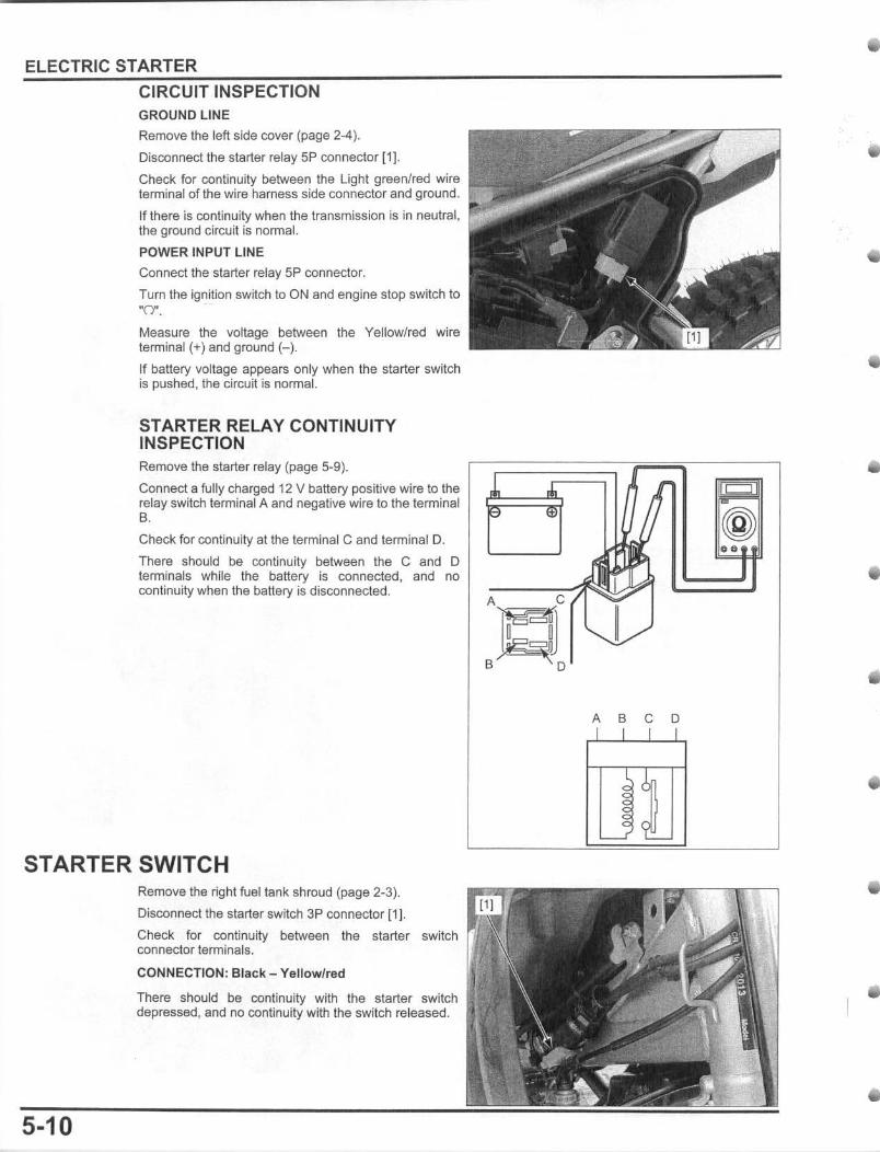
STARTER RELAY CONTINUITY INSPECTION Remove the starter relay (page 5-9).
Connect a fully charged 12 V battery positive wire to the relay switch terminal A and negative wire to the terminal B. Check for continuity al the terminal C and terminal O.
There should be continuity between the C and 0 terminals while the battery is connected. and no continuity when the battery is disconnected.
STARTER SWITCH
5-10
Remove the right rueltank shroud (page 2-3).
Disconnect the starter switch 3P connector [1].
Check for continuity between the starter switch connector terminals.
CONNECTION: Black - Yellow/red
There should be continuity with the starter switch depressed, and no continuity with the switch released.
~ .. r ~ ~ to (@
~ 0. " I
A C / T = B 0
~ ~ ~ ~
i :1:
: 9
NEUTRAL SWITCH INSPECTION Disconnect the neutral switch wire connector [1 ] .
Check for continuity between Ihe switch side Light green/red terminal and ground.
There should be continuity with the transmission is in neutral, and no continuity when Ihe transmission is into gear.
Connect the neutral switch wire connector.
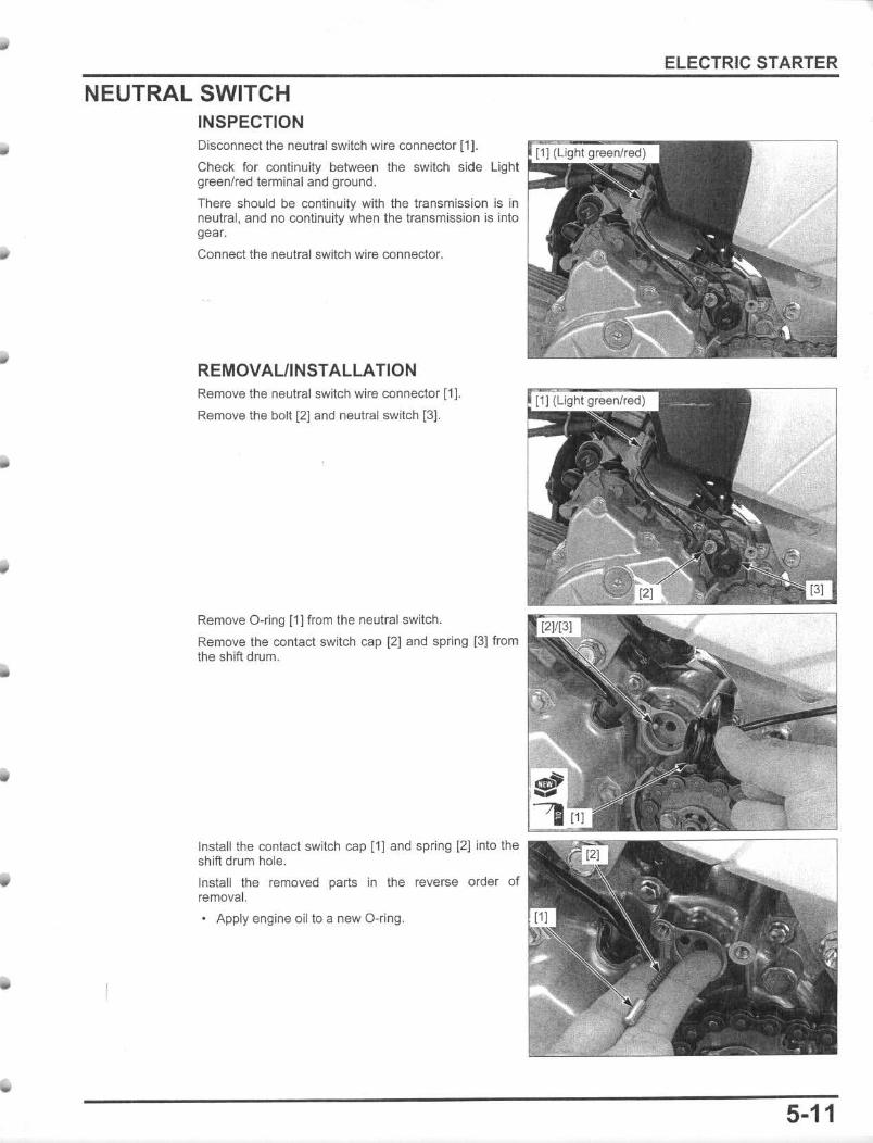
REMOVAUINSTALLATION Remove the neutral switch wire connector [1].
Remove the bolt (2] and neutral switch [3].
Remove O-ring 11J from the neutral switch.
Remove Ihe contact switch cap [2] and spring [3] from the shift drum.
Install the contact switch cap [1] and spring [2) into the shift drum hole.
Install the removed parts in the reverse order of removal.
• Apply engine oil to a new O-ring,
ELECTRIC STARTER
5-11