5 ijaers jul-2015-1-design and development of a cross-ribbon dough mixer
TRANSCRIPT
International Journal of Advanced Engineering Research and Science (IJAERS) [Vol-2, Issue-7, JULY- 2015]
ISSN: 2349-6495
Page | 24
Design and Development of a Cross-Ribbon Dough Mixer
Chikelu C.C., Ude M.U., Onyekwere D.C., Eze N.N., Ukwuani S.T
Projects Development Institute (PRODA), Emene Ind. L/out, Emene, Enugu, Nigeria
Abstract—In bakery industries, mixing is one of the major operations that determine the mechanical properties of dough, which have a direct consequence on the quality of the end product .The mixing operation is to facilitate structure development and ingredients homogenization. In view of the associated problems and difficulties in the manual method of dough mixing, a cross-ribbon dough mixer was designed and developed. The unit parts of the mixer were designed following standard engineering principles for part-sizing, using locally available materials. Whilst the cross-ribbon (suspended on the mixing basin) rotates in clockwise direction, the mixing basin in relative motion rotates in anti-clockwise direction. The mixer was tested to ascertain its performance and it has efficiency of 85.7% with mixing rate of 30kg/hr per batch.
Keywords—Design, development, cross-ribbon, dough, mixing, efficiency, rotation
I. INTRODUCTION
In bakery industries, mixing is one of the major operations that determine the mechanical properties of dough, which have a direct consequence on the quality of the end product (Rosell, and Collar, 2009). The mixing operation is to facilitate structure development and ingredients homogenization (Hwang, and Gunasekaran, 2001). Proper dough development is affected by mixing intensity (mixing speed) and torque imparted (Pastukhov, and Dogan, 2014).To achieve optimal mixing, the flour is placed in a vessel of some type which allows the material to be moved and stirred in a desired pattern at the desired speed and torque This is not as simple as there is no one mixer design that universally satisfies all mixing requirements (Vincent, 1966; Okafor, 2015). Despite so many dough mixers available for small and medium scale productions, manual mixing of dough for economic reasons is still common among developing countries (Vincent, 1966; Okafor, 2015). This manual mixing is very slow and laborious with little or no guarantee of homogeneity of the end product (Oni, et al., 2009). Mixers with impellers such as anchors, gates, or paddle, which produce mainly circumferential flow, perform poorly in mixing because of lack of axial flow to
sweep through the entire vessel (Yeng-Yung Tsui, and Yu-Chang Hu, 2011). Conventional dough mixers such as blade; hook, ribbon and pin-type are commonly used in the industry (Hwang, and Gunasekaran, 2001). In a mixing system with ribbon impellers, mixing proceeds first in the region near the blades and the vessel wall where the material is subjected to high shear strains. Material homogenization is then fulfilled by the axial vortex flow induced by the rotation of the ribbon impeller. It has been shown that this kind of impeller is very effective in mixing high viscous fluids (Gray, 1963; Yeng-Yung Tsui, and Yu-Chang Hu, 2011). However, most of these new machines are expensive and sophisticated in operations for small and medium scale bakeries (Godwin, 1961; Okafor, 2015). Therefore, this research work is devoted to the design, and development of a low cost electric powered cross-ribbon dough mixer that is efficient, easy to operate and maintain for small and medium scale bakeries.
II. MATERIALS AND METHODS 2.1 Materials and Sample Preparation
The cross-ribbon dough mixer is made up of the following component parts; electric motor, the mixing basin, motor pulley, gear box pulley, cross-ribbons attached on the gearbox spindle shaft, flat collar bearings supporting the basin, v-belt and supporting frame. Blend flour (fortified with minerals and vitamins) is purchased from Ogbete main market, Enugu State Nigeria and formulated for bread dough as described by (Campbell, et al., 1993). About 1000g blend flour is mixed with 18g salt, 25g yeast, 610g water and 1g other ingredients using the locally fabricated cross-ribbon mixer until complete dough development as reflected by a rise in dough consistence.
2.2 Design Considerations The major designs of the cross-ribbon dough mixer are on the mixing basin, power requirement; reducer gear; pulley; belt drive; flat collar bearings; cross-ribbon; and the following equations were used to design the unit parts.
2.3 Volume of Mixing Basin In designing for a mixer capable of mixing 1000 g (10kg) of blend flour per batch, at 5inch Hg (16942N/m2 )
International Journal of Advanced Engineering Research and Science (IJAERS) [Vol-2, Issue-7, JULY- 2015]
ISSN: 2349-6495
Page | 25
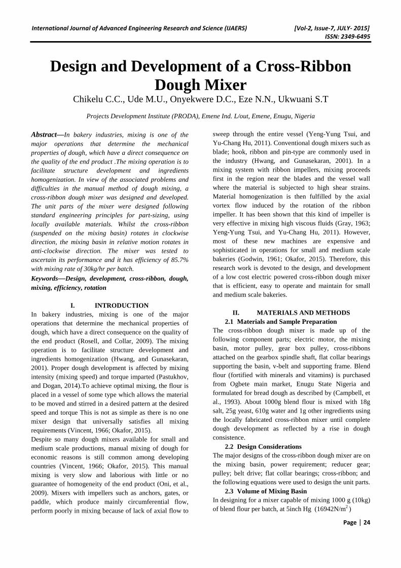
Fig. 1 Side View
mixing pressure, 150rpm ribbon speed, 1.258g/cm3
(1258kg/m3) dough density is used in dough volume calculation (Campbell, et al., 1993)
Dough volume, --------------------------- (1)
Where dough volume (m3), = blend flour mass
(kg) and = dough density (kg/m3). Dough volume =
= 0.00795m3
Assume volume of water + volume of air space + other ingredients = 25%
Thus, Volume of mixing basin, = 0.00795 + (0.25 x
0.00795) = 0.00994m3
2.4 Diameter of the Mixing Basin The diameter of mixing basin is determined with the empirical relationship given below:
Volume of mixing basin, π ---------- (2)
Thus, = ---------------------------------- (3)
Where diameter of mixing basin (m), and
height of mixing basin (m)
Let, = 0.048m; = = 0.513m (513mm)
2.5 Thickness of Mixing Basin
The mixing basin is classified as an open end vessel with only the circumferential or hoop stress induced by the mixing pressure. This circumferential or hoop stress acts in a direction tangential to the circumference of the basin and thickness of mixing basin is determined with the expression by Khurmi and Gupta (2005)
t = ----------------------------------------------- (4)
Where t = thickness of mixing basin (m), p = the mixing pressure (N/m2), d = internal diameter of mixing basin
(m), and = circumferential or hoop stress for steel
material.
Let, p = 16942N/m2, d = 0.513m, = 2.5 x 10⁶N/m2
t = = 0.00174m (1.74mm), and 2mm thick
stainless steel plate is selected. 2.6 Power Requirement
The power which the electric motor must develop to drive the mixer is determined with the expression by Khurmi and Gupta (2005)
P = --------------------------------- (5)
A
C
B
C D
A B C D E F G H
LEGEND Gearbox Pulley Mix ing Basin Flat Collar Bearing Supporting Frame Motor Pulley Cross Ribbon Electric Motor
Spindle Shaft
E
I
G
Belt Drive
I
CROSS - RIBBON DOUGH MIXER
International Journal of Advanced Engineering Research and Science (IJAERS) [Vol-2, Issue-7, JULY- 2015]
ISSN: 2349-6495
Page | 26
Where P = power developed by the electric motor (watts),
= mixing speed (rpm), = torque of the driven
spindle shaft (Nm), = efficiency of the reduction gear
Let, = 150rpm, = 50Nm, = 0.90
P = = 872.78w = 0.873kw (1.2hp).
Therefore, an electric motor of 1.5hp 1440rpm is ideal. 2.7 Selection of Pulleys and Determination of their Speeds The gearbox pulley diameter is determined using the expression for pulley reduction efficiency
Pulley reduction efficiency = =
--------------------------- (6)
For 50% reduction efficiency, 0.5 = => = 0.5 x
= 0.5 x 1440 = 720rpm
Hence, from the empirical relation: = =>
=
Let,
Thus, = = 200mm
Also, the centre distance (x) between two adjacent pulleys is determined using the relation given by Khurmi and
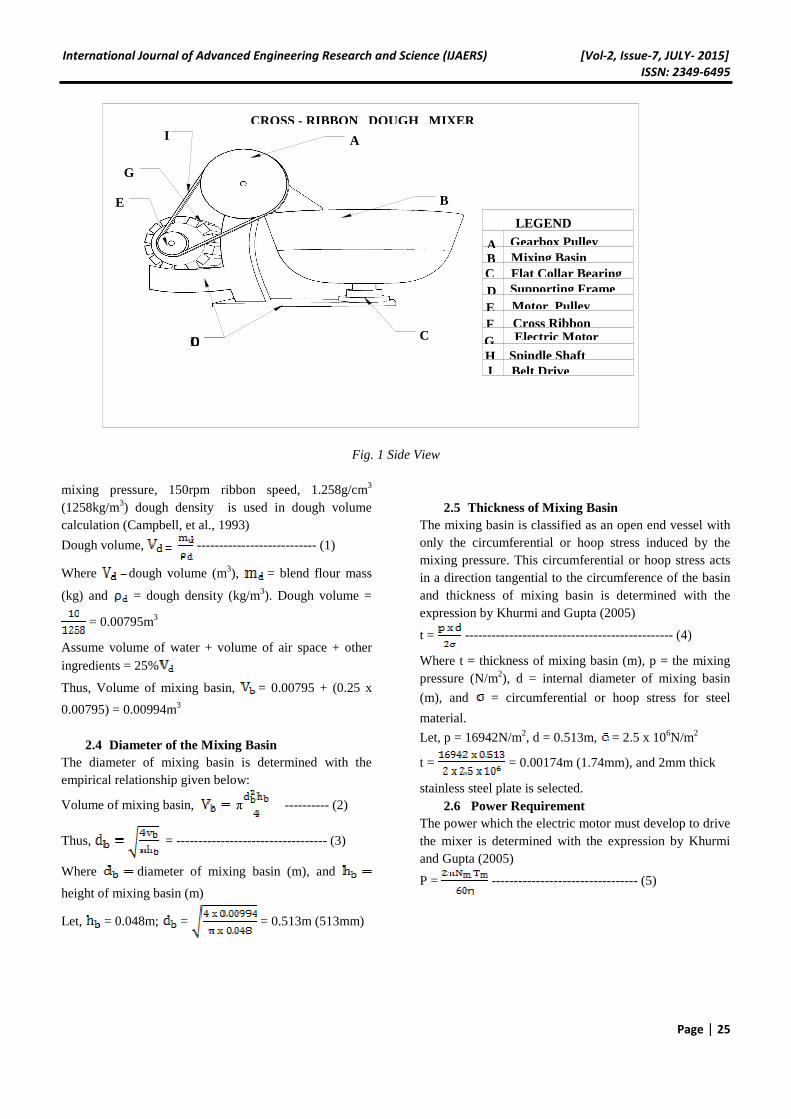
Fig 2. Isometric View
Gupta (2005)
x = --------------------------------- (7)
x = = 250mm
2.8 Gearbox Selection For gearbox reducer speed selection, we need to calculate the gear reduction ratio.
Gear reduction ratio = =
----------------------- (8)
Gear reduction ratio = = 4.8:1
But, for moderate shock agitator and mixers under 10hrs intermittent mixing operation per day, 1.25 service factor is selected (Fenner, 2012). Thus, using the gearbox absorbed power of 0.873kw; the design power is calculated as thus, Design Power = 1.25 x 0.873kw = 1.091kw (1.5hp) This indicates that for a 5/1 gear unit at 150rpm output speed, a 1.5hp motor is required. 2.9 Belt Drive Selection Belt length (L) is determined using the expression given by Khurmi and Gupta (2005)
L = --------------------- (9)
G
A B C
D E F
G H
LEGEND
Gearbox Pulley Mixing Basin Flat Collar Bearing Supporting Frame
Motor Pulley
Cross Ribbon Electric Motor
Spindle Shaft
H
I
F
Belt Drive
CROSS - RIBBON DOUGH MIXER
International Journal of Advanced Engineering Research and Science (IJAERS) [Vol-2, Issue-7, JULY- 2015]
ISSN: 2349-6495
Page | 27
L = = 961mm
The angle of contact of belt on the motor pulley (
= -------------------------------- (10)
Where, sine = = = 0.4
Thus, = 23.58o
Hence, = {180 – 2(23.58)} = 2.32 rad
Now, based on gear reduction ratio 5:1, mixer speed 150rpm, design power 1.5hp, pulley diameters 100mm and 200mm respectively, from standard table (Fenner, 2012) 2spa wedge belt (V-belt) is selected. 2.10 Flat Collar Bearing Design In designing collar bearings, it is assumed that the pressure is distributed uniformly over the bearing surface. The outer diameter of the collar is usually taken as 1.4 to 1.8 times the inner diameter of the collar i.e. diameter of the shaft (Khurmi and Gupta, 2005)
Thus, the bearing pressure () = ------------- (10)
And the expression for total frictional torque (T) is given by Khurmi and Gupta (2005)
T = --------------------------------- (11)
Where, = bearing pressure, W = load transmitted over
the bearing surface, A = cross-sectional area of the
bearing surface = , R = outer radius of the
collar, r = inner radius of the collar, = coefficient of
friction, n = number of collars. Let, W = [(mixing pressure x basin area) + dough weight] = [(16942 x 0.02462) + 10 x 9.8] = [417.17 + 98] =
515.17N, = 3 x 10⁵N/m2, T = 5Nm, = 0.5 and R =
1.6r Then, from equation (11), r = 0.015m (15mm), R = 0.024m (24mm), and also from equation (10), A =
0.001717m2 =
Hence, n = 1.55
2.11 Mixing Efficiency Dough mixing operation at this scale was a batch process and the cross ribbon dough mixer was designed at 35kg/hr per batch. However, during testing, 10kg of blend flour per batch was used and optimum dough development was achieved in 20 minutes. Thus, in 20 minutes, the mixing rate per batch for 10kg =
= 30kg/hr
Hence, mixing efficiency =
= = 85.7%
III. CONCLUSION
A cross-ribbon dough mixer was designed, developed and tested for dough mixing. The mixer was simple enough for local fabrication, operation, repair and maintenance. Powered by a 1.5hp electric motor, the mixer has a mixing efficiency of 85.7%. With this performance, the mixer will culminate the associated problems and difficulties in the manual method of dough mixing. It is, therefore, recommended for both small and medium scale bakers.
REFERENCES [1] G. M. Campbell, C.D. Rielly, P. J. Fryer and P. A
Sadd (1993). Cereal Chem. 70(5): 517-521. [2] Fenner SMSR (2012). Shaft mounted speed reducer
design manual [3] J. O. Godwin, et al. (1961). Mixing Theory. Jerrold
Printing Press, England. [4] J. B. Gray (1963). Batch mixing of viscous liquids.
Chemical Engineering Progress, 59(3): 55-59. [5] C. H. Hwang and S. Gunasekaran (2001).
Determining wheat dough mixing characteristics from power consumption profile of a conventional mixer. Cereal Chem. 78(1): 88-92.
[6] Khurmi et al. (2005). Theory of machines, 14th ed., S. Chand & Co. Ltd, New Delhi.
[7] R. S Khurmi and J. K. Gupta (2005). A Textbook of Machine Design. Eurasia publishing house Ltd, New Delhi.
[8] B. E. Okafor (2015). Design of Power Driven Dough Mixing Machine. Int’l Journal of Engineering and Technology 5(2): 71-74.
[9] O. K. Oni, J. S. Alakali and M. A. Akpapumam (2009). Design, Fabrication and Performance Evaluation of a Powered Soy-Gari Mixer. Journal of Engineering and Applied Sciences 4(3): 164-169.
[10] A. Pastukhov and H. Dogan (2014). Studying of Mixing speed and Temperature impacts on rheological properties of wheat flour dough using Mixolab. Agronomy Research 12(3): 779-786.
[11] C. M Rosell and C. Collar (2009). Effect of Temperature and Consistency on Wheat Dough Performance. Int’l Journal of Food Science and Technology.
[12] Yeng-Yung Tsui and Yu-Chang Hu (2011). Flow Characteristics in Mixers Agitated by Helical Ribbon Blade Impeller. Engineering Applications of Computational Fluid Mechanics 5(3): 416-429.