5 percentile design strength value development for
TRANSCRIPT

214 Industrial Lane
Alum Bank, PA 15221
Telephone: 888.274.7855
www.creativepultrusions.com
PREPARED BY
Dustin Troutman
Director of Marketing &
Product Development
Jeremy Mostoller
Product Design Engineer
April 20, 2016
5th Percentile Design Strength
Value Development for
Pultruded Crossarms
In Support of the Creative Pultrusions, Inc.,
FRP Utility Crossarm Technical Brochure
National Grid FRP Utility Pole and Crossarm Installation

214 Industrial Lane, Alum Bank, PA 15221 | 888.274.7855 | www.creativepultrusions.com 2
Download the CPI FRP Utility Crossarm
brochure: http://www.creativepultrusions.com/index.cfm/ pultruded-systems/fiberglass-crossarms-and-tangent- crossarms/crossarm-brochure/
Introduction
In 2007, the National Electric Safety Code
(NESC) standards committee adopted
composite poles, crossarms and braces into
the code. This action was a significant step in
mandating that the composite electrical
structures manufacturing industry publish
their design strength values to a 5% Lower
Exclusion Limit (LEL). Utilities that are
designing structures with the NESC requires
manufactures to publish their design values
to the 5th percentile strength. This paper
creates transparency for the utility engineer,
in that it describes the test methods, test
setup, statistical calculations and relevant
standards that were used to generate 5th
percentile design strength values for the
CP2500 crossarm, as published in the
Creative Pultrusions’ FRP Utility Crossarm
Brochure.
The Creative Pultrusions’ crossarms have all
been evaluated per ASTM D8019-15.
Standard Test Methods for Determining the
Full Section Flexural Modulus and Bending
Strength of Fiber Reinforced Polymer
Crossarms Assembled with Center Mount
Brackets.
Investigation
The following mechanical characteristics
were evaluated in order to obtain the 5th
percentile strength values for design,
standards development and quality control
purposes:
• Bending Strength at Failure for
Deadend and Tangent Crossarm
Configurations
• In-plane Shear Strength at Failure
• Flexural Modulus of Elasticity
• Pin-Bearing Strength at Failure
• Minor Axis Bending Strengths for
Deadend Crossarms
• Deadend Bracket Guy Mount Testing
214 Industrial Lane, Alum Bank, PA 15221 | 888.274.7855 | www.creativepultrusions.com 3
Experiment
Bending Strength, In-plane Shear Strength,
Pin-bearing Strength and Flexural Modulus of
Elasticity
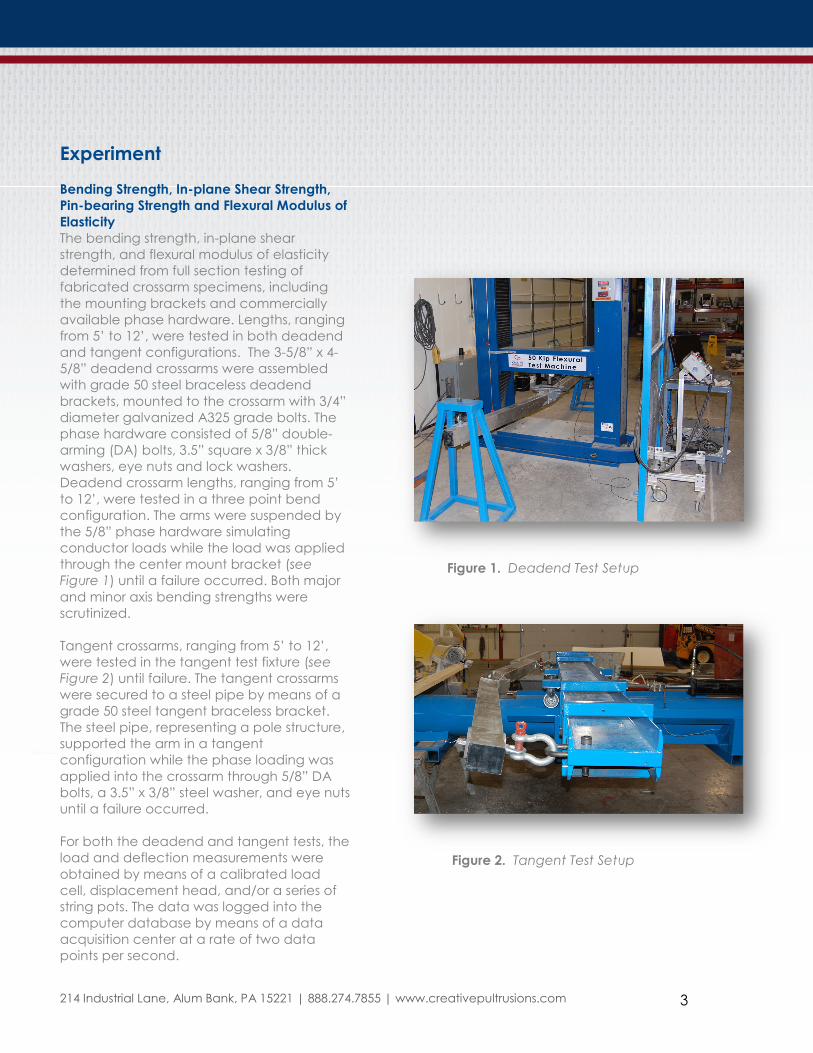
The bending strength, in-plane shear
strength, and flexural modulus of elasticity
determined from full section testing of
fabricated crossarm specimens, including
the mounting brackets and commercially
available phase hardware. Lengths, ranging
from 5’ to 12’, were tested in both deadend
and tangent configurations. The 3-5/8” x 4-
5/8” deadend crossarms were assembled
with grade 50 steel braceless deadend
brackets, mounted to the crossarm with 3/4”
diameter galvanized A325 grade bolts. The
phase hardware consisted of 5/8” double-
arming (DA) bolts, 3.5” square x 3/8” thick
washers, eye nuts and lock washers.
Deadend crossarm lengths, ranging from 5’
to 12’, were tested in a three point bend
configuration. The arms were suspended by
the 5/8” phase hardware simulating
conductor loads while the load was applied
through the center mount bracket (see
Figure 1) until a failure occurred. Both major
and minor axis bending strengths were
scrutinized.
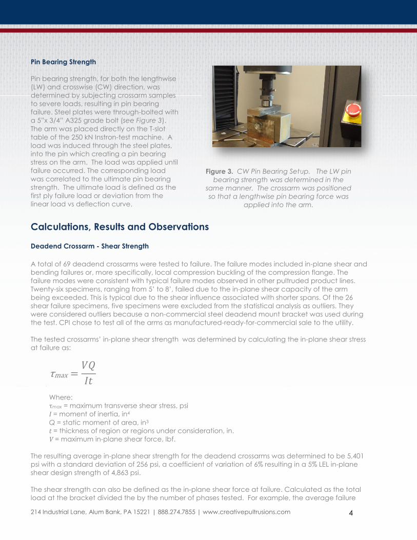
Tangent crossarms, ranging from 5’ to 12’,
were tested in the tangent test fixture (see
Figure 2) until failure. The tangent crossarms
were secured to a steel pipe by means of a
grade 50 steel tangent braceless bracket.
The steel pipe, representing a pole structure,
supported the arm in a tangent
configuration while the phase loading was
applied into the crossarm through 5/8” DA
bolts, a 3.5” x 3/8” steel washer, and eye nuts
until a failure occurred.
For both the deadend and tangent tests, the
load and deflection measurements were
obtained by means of a calibrated load
cell, displacement head, and/or a series of
string pots. The data was logged into the
computer database by means of a data
Figure 1. Deadend Test Setup
Figure 2. Tangent Test Setup
acquisition center at a rate of two data
points per second.
214 Industrial Lane, Alum Bank, PA 15221 | 888.274.7855 | www.creativepultrusions.com 4
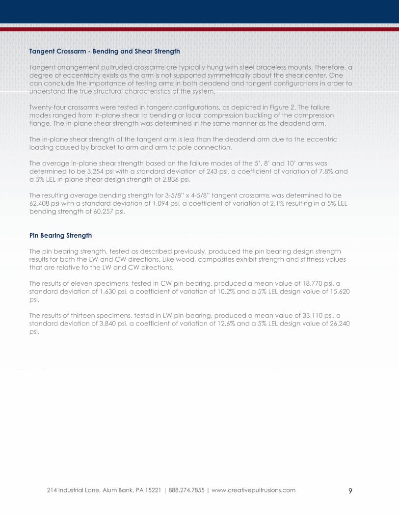
Pin Bearing Strength
Pin bearing strength, for both the lengthwise
(LW) and crosswise (CW) direction, was
determined by subjecting crossarm samples
to severe loads, resulting in pin bearing
failure. Steel plates were through-bolted with
a 5”x 3/4” A325 grade bolt (see Figure 3).
The arm was placed directly on the T-slot
table of the 250 kN Instron-test machine. A
load was induced through the steel plates,
into the pin which creating a pin bearing
stress on the arm. The load was applied until
failure occurred. The corresponding load
was correlated to the ultimate pin bearing
strength. The ultimate load is defined as the
first ply failure load or deviation from the
linear load vs deflection curve.
Figure 3. CW Pin Bearing Setup. The LW pin
bearing strength was determined in the
same manner. The crossarm was positioned
so that a lengthwise pin bearing force was
applied into the arm.
Calculations, Results and Observations
Deadend Crossarm - Shear Strength
A total of 69 deadend crossarms were tested to failure. The failure modes included in-plane shear and
bending failures or, more specifically, local compression buckling of the compression flange. The
failure modes were consistent with typical failure modes observed in other pultruded product lines.
Twenty-six specimens, ranging from 5’ to 8’, failed due to the in-plane shear capacity of the arm
being exceeded. This is typical due to the shear influence associated with shorter spans. Of the 26
shear failure specimens, five specimens were excluded from the statistical analysis as outliers. They
were considered outliers because a non-commercial steel deadend mount bracket was used during
the test. CPI chose to test all of the arms as manufactured-ready-for-commercial sale to the utility.
The tested crossarms’ in-plane shear strength was determined by calculating the in-plane shear stress
at failure as:
τmax ���
�
Where:
τmax = maximum transverse shear stress, psi
I = moment of inertia, in4
Q = static moment of area, in3
t = thickness of region or regions under consideration, in.
V = maximum in-plane shear force, lbf.
The resulting average in-plane shear strength for the deadend crossarms was determined to be 5,401
psi with a standard deviation of 256 psi, a coefficient of variation of 6% resulting in a 5% LEL in-plane
shear design strength of 4,863 psi.
The shear strength can also be defined as the in-plane shear force at failure. Calculated as the total
load at the bracket divided the by the number of phases tested. For example, the average failure

214 Industrial Lane, Alum Bank, PA 15221 | 888.274.7855 | www.creativepultrusions.com 5
load of a 5’ CP2500 crossarm was determined to be 20,919 lbf applied to the center mount bracket.
The resulting shear force equates to the total load divided by 2 or 10,459 lbf.
The average shear force at failure was utilized to establish the phase loading capacity for arms with
four phases. The sum of the phase loads, on either side of the center mount, must be less than the
shear force measured for two phase condition. The assumption was made that the same installation
parameters will be used for each of the phases. Therefore, the four phase allowable loading is equal
to the total applied average load divided by 4, or 5,230 lbf. The 5% LEL phase load capacities were
derived by utilizing the LEL shear force at failure derived from the crossarms that were tested per ASTM
D8019-15. Note: The literature values were rounded down to the nearest 100 lbs.
Figure 4. Typical In-plane Shear Failure at the Neutral Axis
Deadend Crossarm - Major Axis Bending Strength
Twenty-three of the 69, major axis tested, deadend crossarms tested failed due to local compression
buckling of the compression flange. The 10’ and 12’ deadend arms failed in this manner due to the
heavy influence of bending stresses associated with longer spans. The compression stress at failure
was determined by computing the induced moment at failure and dividing by the section modulus of
the 3-5/8” x 4-5/8” hollow rectangular crossarm. The analysis considers the arm to be in a four-point
bend scenario by distributing the applied load at the centermount to the two bolts mounting the
centermount to the crossarm.

214 Industrial Lane, Alum Bank, PA 15221 | 888.274.7855 | www.creativepultrusions.com 6
Figure 5. Local Compression Buckling Failure
Therefore, the bending stress at failure was calculated by solving for ssss, , , , where:
�� ���
�
And: �� = stress due to bending, psi � = maximum load acting through a single center mount bolt, lbf. �= section modulus about the neutral axis, in3 �= distance from phase hardware to the center mount, in
Figure 6. Load Diagram

214 Industrial Lane, Alum Bank, PA 15221 | 888.274.7855 | www.creativepultrusions.com 7
The resulting average bending strength for the deadend crossarms was determined to be 80,900 psi
with a standard deviation of 2,377 psi, a coefficient of variation of 3% resulting in a 5% LEL bending
design strength of 76,688 psi.
Deadend Crossarm – Minor-Axis Bending Strength
Figure 7. Minor-axis Bending Strength Test Setup
Both the major axis and minor axis bending strengths have been determined and documented. A
typical deadend crossarm exhibits a major and minor axis bending stress due to catenary angles and
line tension. Utility design engineers can evaluate their major and minor axis loads against the
published design values.
The minor axis bending strength of the deadend crossarm was determined by testing 20 crossarms
ranging from 5’ to 12’ in length. The crossarms were loaded in the tangent test fixture with typical
deadend hardware in order to impose transverse loads on the crossarm. The typical failure mode was
local compression buckling at the arm and deadend bracket interface as depicted in the following
photo.

214 Industrial Lane, Alum Bank, PA 15221 | 888.274.7855 | www.creativepultrusions.com 8
Figure 8. Minor-axis Bending Failure Mode
Deadend Crossarm - Major Axis Flexural Modulus
The flexural modulus of elasticity was determined by analyzing the load versus deflection data of
spans with span-to-depth ratio greater than 16:1. Specifically, data collected for the 10’ and 12’
crossarms tested in the major axis deadend configuration was utilized to calculate flexural modulus.
The flexural modulus was calculated by analyzing the crossarm in a four point bend configuration. The
resultant is based on a minimum of five data points extracted between 30% and 70% of the ultimate
load.
The flexural modulus was determined by solving for E where:
� � ���3�� � 4���
24��
where:
a = distance from phase hardware to the center mount bolt
through the crossarm. in.
E = flexural modulus, psi
I = moment of inertia about the neutral axis of the crossarm, in.4
L = support span, in.
P = load acting through a single center mount bolt, lbf.
δ = deflection relative to the applied load, in.
The average modulus of elasticity was determined to be 6.02E6 psi. The coefficient of variation was
2%. The average modulus of elasticity should be used for predicting the deflection of a pultruded
crossarm. Therefore, the flexural modulus is not factored based on a 5% LEL.
214 Industrial Lane, Alum Bank, PA 15221 | 888.274.7855 | www.creativepultrusions.com 9
Tangent Crossarm - Bending and Shear Strength
Tangent arrangement pultruded crossarms are typically hung with steel braceless mounts. Therefore, a
degree of eccentricity exists as the arm is not supported symmetrically about the shear center. One
can conclude the importance of testing arms in both deadend and tangent configurations in order to
understand the true structural characteristics of the system.
Twenty-four crossarms were tested in tangent configurations, as depicted in Figure 2. The failure
modes ranged from in-plane shear to bending or local compression buckling of the compression
flange. The in-plane shear strength was determined in the same manner as the deadend arm.
The in-plane shear strength of the tangent arm is less than the deadend arm due to the eccentric
loading caused by bracket to arm and arm to pole connection.
The average in-plane shear strength based on the failure modes of the 5’, 8’ and 10’ arms was
determined to be 3,254 psi with a standard deviation of 243 psi, a coefficient of variation of 7.8% and
a 5% LEL in-plane shear design strength of 2,836 psi.
The resulting average bending strength for 3-5/8” x 4-5/8” tangent crossarms was determined to be
62,408 psi with a standard deviation of 1,094 psi, a coefficient of variation of 2.1% resulting in a 5% LEL
bending strength of 60,257 psi.
Pin Bearing Strength
The pin bearing strength, tested as described previously, produced the pin bearing design strength
results for both the LW and CW directions. Like wood, composites exhibit strength and stiffness values
that are relative to the LW and CW directions.
The results of eleven specimens, tested in CW pin-bearing, produced a mean value of 18,770 psi, a
standard deviation of 1,630 psi, a coefficient of variation of 10.2% and a 5% LEL design value of 15,620
psi.
The results of thirteen specimens, tested in LW pin-bearing, produced a mean value of 33,110 psi, a
standard deviation of 3,840 psi, a coefficient of variation of 12.6% and a 5% LEL design value of 26,240
psi.

214 Industrial Lane, Alum Bank, PA 15221 | 888.274.7855 | www.creativepultrusions.com 10
Figure 9. Typical CW Pin Bearing Failure
None of the full-section arms failed in pin bearing during the full-section testing. Therefore, lab
specimens were utilized to produce the pin bearing design strength values.
Deadend Mount Guy Attachment Capacity
The capacity of the CP2500 deadend bracket guy attachment was evaluated by physically loading
the brackets at guy angles including 30°, 45° and 90°. The 90° degree direction is parallel to the phase.
Each guy hole was loaded independently.
Figure 10. Deadend Guy Bracket Guy Testing

214 Industrial Lane, Alum Bank, PA 15221 | 888.274.7855 | www.creativepultrusions.com 11
Figure 11. Deadend Guy Bracket Guy Testing Results
The 30° and 45° tests demonstrated a capacity of over 36,000 lbf. per guy hole before the test was
stopped. There was no sign of large scale yielding within the bracket. Slope changes observed in the
load curves are the result of yielding of the bolts attaching the bracket to the fixture. The 90° degree
test force deformed the bracket yielding the steel at 28,000 lbf.
Phase Capacity
The phase capacities, corresponding to each arm length and type, were derived based on the
governing failure stresses. The published phase capacity charts consider the arm length, phase
positions and phase quantities for both deadend and tangent crossarms. The 5% LEL and average in-
plane shear and bending stresses for each scenario, described in the technical data charts of the CPI
FRP Utility Crossarm Technical brochure, dictate the phase capacity. The phase capacity, published
for each scenario, represents the behavior of the arm described. In the event the utility utilizes the
arm in a different manner, the phase capacity described may not be relevant.
The approach of publishing phase capacities, as well as the mechanical properties, permits CPI’s
engineering team and the utility engineer to analyze various arm lengths, phase positions and phase
quantities that are specific to the application.
0.00E+00
5.00E+03
1.00E+04
1.50E+04
2.00E+04
2.50E+04
3.00E+04
3.50E+04
4.00E+04
1 126 251 376 501 626 751 876 1001 1126 1251 1376 1501
Applied Load, lb
Data Point
Load Curve of STL083 Guy Loading
30 Degree Top Hole
30 Degree Lower Hole
45 Degree Top Hole
45 Degree Lower Hole
90 Degree Top Hole
90 Degree Lower Hole

214 Industrial Lane, Alum Bank, PA 15221 | 888.274.7855 | www.creativepultrusions.com 12
Bolt Torque Protection
Over-torque protection is achieved with Creatives patented torque protection system. The system
has been tested with torque wrenches and impact wrenches. Creative’s guarantees torque
protection up to 250 lbf-ft. Testing indicated that torque loads up to 500 lbf.-ft. can be tolerated.
Load Applied (lbf.-ft.) Observations
250 - 300 No cracking or visual damage
400 - 450 No cracking or visual damage
450 - 500 No cracking or visual damage
570 Cracking occurred at radius/flat interface on the 3-
5/8 inch surface of the TR410 crossarm
Figure 12. Torque Test Results Calibrated Torque Wrench
Figure 13. Torque Test with Impact Wrench
Observations
Failure modes are dictated by the arm length, phase position, phase quantities and hardware details.
In some instances, the hardware governs the capacity of the crossarm. The utility is cautioned to
validate that the proper hardware is utilized in the field. If the vendor calls out a specific washer size, it
is important that the correct washer be utilized. A good example is the failure mode of the washer

214 Industrial Lane, Alum Bank, PA 15221 | 888.274.7855 | www.creativepultrusions.com 13
pulling through the end of the arm. This failure mode is caused by using an improperly sized square
washer.
Figure 12. Failure Caused by Improper Washer Size
The vendor is responsible to provide the utility with sound engineering design values. The utility should
validate the degree to which the values have been statistically manipulated. If the utility is utilizing the
NESC, the values should be published as 5% Lower Exclusion Limit Design Values.
It was observed that the in-plane shear strength of the 3-5/8” x 4-5/8” crossarm varied based on the
arm being tested as a tangent or a deadend. The actual in-plane shear strength of the material did
not change. The change is due to the center mount and eccentricity that exists with a tangent arm
configuration. The near pole web of the crossarm profile is loaded at a higher rate than the far side
due to the inherent bracket assembly.
The 5% in-plane shear strength of the tangent arm is approximately 2,836 psi, while the deadend arm
exhibited an in-plane shear strength of 4,863 psi. The % in-plane shear strength reduction is 42% for the
tangent configuration. One can conclude that it is important to test the tangent arm in a tangent
configuration in order to obtain the system behavior and the true design strengths.
As companies, industries, and product lines mature, tribal knowledge is eventually captured and
communicated in terms of specifications, codes and standards. The pultruded crossarm industry has
matured significantly over the last twenty years. The most significant upswing in crossarm usage has
been over the last ten years with the trend line aggressively pointing upward. The upward trend is due
to the utilities’ desire to increase grid reliability, enhance safety and to reduce labor.
Over the next three years, the composites industry will be introducing more codes and standards for
crossarms and poles. The standards will further secure the use of pultruded arms and poles and will
permit effective communication between manufactures and end users, resulting in grid and product
reliability. You are encouraged to procure the ASTM crossarm test standard by downloading: ASTM D8019 - 15 Standard Test Methods for Determining the Full Section Flexural Modulus and
Bending Strength of Fiber Reinforced Polymer Crossarms Assembled with Center Mount Brackets

214 Industrial Lane, Alum Bank, PA 15221 | 888.274.7855 | www.creativepultrusions.com 14
Concluding Points
• 5th Percentile design values have been determined and documented, for each crossarm
model, in CPI’s crossarm brochure which can be accessed by clicking:
http://www.creativepultrusions.com/index.cfm/fiberglass-pultruded-systems/fiberglass-
crossarms-and-tangent-crossarms/crossarm-brochure/
• This white paper provides transparency for utility standards engineers so they can
understand how crossarm strength values were derived by CPI.
• It is important that the utility standards engineer verify that the design values are
published to a 5% lower exclusion limit.
• It is important to understand that the manufacturer or the engineer of record must be
consulted if the crossarms are to be loaded in a fashion not described in the
manufacturer’s literature.
• CPI provides the necessary information for the engineer of record to determine the
crossarm behavior for load scenarios not described in the brochure.
• Torque Testing, utilizing Creative’s patented torque protection system, indicated that a
torque capacity of 500 lbf-ft can be tolerated, but not recommended.
• Utilities are encouraged to mandate that the FRP crossarm supplier test their arms in
accordance with ASTM D8019-15.