5. radiation measurements: instruments and methods
TRANSCRIPT

Diana Adlienė
Department of Physics
Kaunas University of Technology
5. Radiation Measurements:
Instruments And Methods
Joint innovative training and teaching/
learning program in enhancing development
and transfer knowledge of application of
ionizing radiation in materials processing

This project has been funded with support from the European
Commission. This publication reflects the views only of the author.
Polish National Agency and the Commission cannot be held
responsible for any use which may be made of the information
contained therein.
Date: Oct. 2017
Joint innovative training and teaching/ learning program in enhancing development and transfer
knowledge of application of ionizing radiation in materials processing
This presentation contains some information
addapted from open access education and training
materials provided by IAEA
DISCLAIMER

INTRODUCTORY NOTES
• Radiation measurements cover a broad area of
instruments and methods focusing on measurements
of different parameters of radiation;
• Dose measurements play a fundamental role in
radiation processing of materials:
� Validation and radiation process control depend on the measurement of absorbed dose;
� Measurements of absorbed dose shall be performed using a dosimetric system or systems having a known level of accuracy and precision;
� The calibration of each dosimetric system shall be traceableto an appropriate national standard.

INTRODUCTORY NOTES
This presentation is focused on dose measurements
from two points of wiev:1. Instruments and methods for absorbed dose
measurements, validation and verification.
2. Instruments and methods for dose monitoring
(occupational dosimetry)
NoteMeasurements of irradiation process parameters, dosimetry issues for QC
and QA in radiation processing will be covered during practical training
and in the future lecture of dr. G. Przybytniak

1. Classification of dosimetry systems;
2. Selection of dosimetry systems;
3. Characterization of dosimetry systems: Instruments and
methods.
Note
Futher reading is suggested: Guidelines for the
development, validation and routine control of industrial
radiation process. IAEA, Vienna, 2013
TABLE OF CONTENTS

CLASSIFICATION OF DOSIMETRY SYSTEMS
Classification of dosimetry systems is based on:
- metrological properties of the dosemeter
- field of application

New addition: E 2628 – 09 (ASTM Standard);
System classification based on metrological properties (type I and II);
Type I:
dosemeter of high metrological quality which response is affected by individual influence quantities in a well defined way so, that it can be expressed in terms of independent correction factors;
Fricke, dichromate, ceric-cerous sulphate, Ethanol-chlorobenzene solution (ECB), alanine/EPR dosemeters
Type II:
dosemeter, which response is affected by influence quantities in a complex way – cannot be expressed in terms of independent correction factors;
Process calorimeter, Cellulose triacetate (CTA), LiF, PMMA, perspex systems, radiochromic films.
CLASSIFICATION OF DOSIMETRY SYSTEMS

System classification based on field of application
Reference standard systems (type I);
Used to calibrate dosimeters for routine use, therefore high metrological qualities, low uncertainty and traceability to appropriate national or international standards are needed.+/- 3 % (k = 2);
Fricke solution, alanine/ EPR dosimeter system, potassium dichromate solution,
ceric-cerous sulphate solution and ethanol-monochlorobenzene (ECB) solution).
Routine systems (type II);
Used for routine absorbed dose measurements (i.e. dosemapping and process monitoring). Traceability to national orinternational standards is needed. +/- 6 % (k = 2);
Perspex systems, ECB, cellulose triacetate, Sunna film and radiochromic films such as FWT-60 and B3/GEX)
CLASSIFICATION OF DOSIMETRY SYSTEMS

HIERARCHY OF STANDARDS
PSDL: Standards laboratory
Calorimeters, ionization chambers [Dw, Gy (±1%) D
w, kGy (±2%)]
|
SSDL: Reference standard dosimetry systems (±3%)
Fricke, ceric, dichromate, alanine, calorimeters, ECB, ionization chambers
|
Transfer standard dosimetry systems
Alanine; ethanol-chlorobenzene (ECB); potassium dichromate; ceric-cerous
|
Routine dosimetry systems (±6%)
Films, plastics, dyed plastics, TLD, OSLD, semiconductor devices …
Certificates issued by a NMI or a laboratory accredited to ISO 17025 can be taken as proof of traceability and no further action is required by the user.
• Primary standards are instruments of the highest metrological quality that permit determination of the unit of a quantity from its definition, the accuracy of which has been verified by comparison with standards of other institutions of the same level.
• Primary standards are realized by the primary standards dosimetry laboratories (PSDLs) in about 20 countries worldwide.
• Regular international comparisons between the PSDLs, and with the Bureau International des Poids et Mesures (BIPM), ensure international consistency of the dosimetry standards.
PRIMARY STANDARDS

1
•Radiation detectors used for calibration of radiation beams (industry, medicine) must have a calibration coefficient traceable (directly or indirectly) to a primary standard.
• Primary standards are not used for routine calibrations, since they represent the unit for the quantity at all times.
• Instead, the PSDLs calibrate secondary standard dosimeters for secondary standards dosimetry laboratories (SSDLs) that in turn are used for calibrating the reference instruments of users, such as therapy level ionization chambers (hospitals) or calorimeters (radiation processing)
PRIMARY STANDARDS

Reference standard system
• Dosimeters of high metrological quality are used as a standard to provide measurements traceable to measurements made by primary standard systems.
Transfer standard system
• Intermediary system with high metrological qualities,suitable for transferring dose information from anaccredited/standard laboratory to an irradiation facility toestablish traceability (comparing absorbed dosemeasurements). Dosimetry intercomparison exercises arerequested.
Both systems require calibration
REFERENCE AND TRANSFER STANDARD SYSTEMS

TRACEABILITY
The ISO defines measurement traceability as:
“Property of the result of a measurement or the value of a standard whereby it can be related to stated references, usually national or international standards, through an unbroken chain of comparisons all having stated uncertainties.”
____________________________
comparison = calibration

ACCURACY AND PRECISION
Accuracy specifies the proximity of the mean value of a measurement to the true value.
Precision specifies the degree of reproducibility of a measurement.
Note:
High precision is equivalent to
a small standard deviation.

ACCURACY AND PRECISION
The accuracy and precision associated with a measurement is
often expressed in terms of uncertainty (ISO guidelines)
High precision
High accuracy
High precision
Low accuracy
Low precision
High accuracy
Low precision
Low accuracy

UNCERTAINTIES
The result of a (dose) measurement is only an approximation or estimate of the (dose) value and it is complete only when accompanied by a quantitative statement of its uncertainty:
Absorbed dose = 27.4 +/- 0.55 kGy
Formal definition of uncertainty:
Uncertainty is a parameter associated with the result of a measurement. It characterizes the dispersion of the values (= range of the values) that could reasonably be attributed to the measurand (=absorbed dose).
Note:
Quantities such as the "true value" and the deviation from it, the "error", are basically unknowable quantities. Therefore, these terms are not used in the "Guide to the expression of uncertainty".

UNCERTAINTIES
• In general terms, measurement uncertainty can be regarded as the probability that the measurement lies within a range of values, i.e. it is a statistical concept.
•To a good approximation, the distribution of possible values often follows a Gaussian or normal distribution.

UNCERTAINTIES
There two types of uncertainties that should be investigated performing measurements:
Type A uncertainties (random) are evaluated by statistical analysis of series of measurements (e.g. standard deviation of the mean) and are related mainly to precision (i.e. reproducibility) of the dosimeter response.
Type B uncertainties (non-random, systematic) are evaluated by means other than statistical analysis (based on scientific judgement, e.g. previous experimental data) – B type (non-random, systematic) and are related mainly to calibration (accuracy).

UNCERTAINTIES
Type A standard uncertainties, uA:
If a measurement of a dosimetric quantity x is repeated Ntimes, then the best estimate for x is the arithmetic mean of all measurements xi
1
1N
i
i
x xN
=
= ∑
The standard deviation σx is used to express the uncertainty
for an individual result xi:
( )2
1
1
1
N
x i
i
x xN
σ
=
= −
−
∑

UNCERTAINTIES
The standard deviation of the mean value is used to express the uncertainty for the best estimate:
The standard uncertainty of type A, denoted uA, is defined as the standard deviation of the mean value
( )( )
2
1
1 1
1
N
x ix
i
x xN NN
σ σ
=
= = −
−
∑
A xu σ=

UNCERTAINTIES
Type B standard uncertainties, uB:
• If the uncertainty of an input component cannot be estimated by repeated measurements, the determination must be based on other methods such as intelligent guesses or scientific judgments.
•Type B uncertainties may be involved in:
• influence factors on the measuring process
• the application of correction factors
• physical data taken from the literature
UNCERTAINTIES
Combined uncertainty
Having evaluated standard uncertainties associated with each component of measurement, the combined uncertainty, uC, associated with a particular measurement is obtained by summing in quadrature standard uncertainties of the individual component , i.e. by taking the square root of the sum of the squares of the individual components:
uc = (u12 + u2
2 + u32 + .....)½

UNCERTAINTIES
Expanded uncertainties, U:
The combined uncertainty is assumed to exhibit a
normal distribution.Then the combined standard uncertainty uC corresponds to a confidence level of 67% .A higher confidence level is obtained by multiplying uC
with a coverage factor denoted by k:
For k = 2, the expanded uncertainty corresponds to the 95% confidence level.
CU k u= ⋅

SELECTION OF DOSIMETRY SYSTEM
Application criteria is most important one for the selection of a suitable dosimetry system:
• Industry, medicine, research;
• Reference, transfer, routine standard;
• Absorbed dose, dose rate, dose equivalent;
• Active or passive;
• Solid, liquid, gaseous…..
When selected, central attention has to be paid to the properties of dose measuring devices (dosemeters)

GENERAL REQUIREMENTS FOR DOSEMETERS
� High accuracy and precision;
� Linearity of signal with dose over a wide range;
� Small dose and dose rate dependence;
� Flat energy response;
� Small directional dependence;
� High spatial resolution;
� Large dynamic range;
� Stability of dosemeter response;
� High detection efficiency;
� Etc…..

DOSEMETER‘S PROPERTIES
Linearity: the dosemeter reading should be linearly proportional to the dosimetric quantity.
Case A:
• Linearity;
• Supralinearity;
• Saturation;
Case B:
• Linearity;
• Saturation.

DOSEMETER‘S PROPERTIES
Dose rate dependence
� M/D may be called the response of a dosimeter system
� When an integrated response is measured,
the dosimetric quantity should be independent of the dose rate dD/dt of the quantity.
� Other formulation:The response M/D should be constant for different dose rates (dD/dt)
1 and (dD/dt)
2.
( / ) (d / d )dM M D D t t= ∫
( / ) (d / d )dM M D D t t= ∫

DOSEMETER‘S PROPERTIES
Energy dependence
• The response of a dosimetricsystem is generally a function of the radiation energy.
• Since calibration is done at a specified beam quality (=energy), a reading should generally be corrected if the user's beam quality is not identical to the calibration
beam quality.
Energy dependence of film dosemeter

DOSEMETER‘S PROPERTIES
Directional dependence
• The variation in response as a function of the angle of the incidence of the radiation is called the directional dependence of a dosimeter.
•Due to construction details and physical size, dosimeters usually exhibit a certain directional dependence.

DOSEMETER‘S PROPERTIES
Spatial resolution and physical size
•The quantity absorbed dose is a point quantity
• Ideal measurement requires a point-like detector
•Examples that approximate a ‘point’ measurement are:
� TLD;
� film, gel, where the ‘point’ is defined by the
resolution of the
read-out system)
� pin-point micro-chamber
2 mm

DOSIMETRY METHODS
Dosimetry methods depend on radiation induced processes in
detector materials:
- Ionization (ionization chambers),
- Temperature change (calorimeters);
- Thermoluminescence (LiF);
- Colour change (perspex, radiochromic systems);
- Free radical concentration change (alanine);
- Conductivity change (ECB, alanine solution);
- Radiation chemical oxidation (Fricke);
- Radiation chemical reduction (dichromate, ceric-cerous);
- Optically stimulated luminescence (Al2O3, Sunna);
- Radiation defects in semiconductors (diodes, MOSFET
(and many others);

DOSIMETRY: INSTRUMENTS AND METHODS
Primary standard methods
�Calorimetry and ionization methods are considered primary standard methods in dosimetry;
�Both methods enable dose measurements in various radiation fields and are used for calibration of standard and routine dosemeters
Calorimetry is widely used in radiation processing of materials, while ionization chambers – in medical applications of ionizing radiation

GAS FILLED DETECTORS
Operation scheme of gas filled detector
Ionization chamber is a detector consisting of a chamber
filled with gas, in which the electric field provided for the
collection of ions (charges) produced by ionizing
radiation in the measuring volume of the detector, is
insufficient to initiate gas multiplication
PRIMARY STANDARD: IONIZATION CHAMBERS
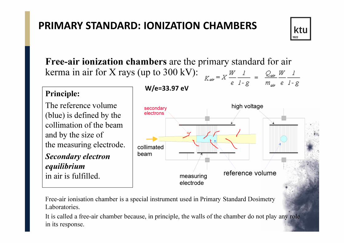
Free-air ionization chambers are the primary standard for air kerma in air for X rays (up to 300 kV):
reference volume
high voltage
measuring
electrode
collimatedbeam
secondaryelectrons
Principle:
The reference volume
(blue) is defined by the
collimation of the beam
and by the size of
the measuring electrode.
Secondary electron
equilibrium
in air is fulfilled.
Free-air ionisation chamber is a special instrument used in Primary Standard Dosimetry
Laboratories.
It is called a free-air chamber because, in principle, the walls of the chamber do not play any role
in its response.
W/e=33.97 eV

PRIMARY STANDARD – FREE AIR CHAMBER
Uncertainty

PRIMARY STANDARD: IONIZATION CHAMBERS
� Free-air ionization chambers cannot function as a primary standard for 60Co beams or high energy photons and electrons beams generated in medical accelerators , since the air column surrounding the sensitive volume (for establishing the electronic equilibrium condition in air) would become very long.
� Therefore at energies > 300 kV :
•Graphite cavity ionization chambers with an accurately known chamber volume are used as the primary standard.
• The use of the graphite cavity chamber is based on the Bragg–Gray cavity theory.

PRIMARY STANDARD: IONIZATION CHAMBER
Farmer type ionization chamber is used for the determination of the absorbed dose to water, D
w, which is the basic
measurand in clinical operation at the primary standard level
Note:
Ideally, the primary standard for absorbed dose to water should be a water calorimeter that would be an integral part of a water phantom and would measure the dose under reference conditions.
central collecting electrode
gas filled cavity
outer wall

PRIMARY STANDARD: CALORIMETER
�Calorimetry is the most fundamental method of realizing the primary standard for absorbed dose, since temperature rise is the most direct consequence of energy absorption in a medium.
�Calorimetry is absolute method of dosimetry where almost all radiation energy absorbed in the thermally isolated mass is converted into heat which is measured.
� Measured energy per unit mass or the average dose to the medium assuming no heat loss is:
h is specific heat capacity of the medium; δ is the thermal defect (this small fraction of the energy that does not appear eventually as thermal energy –because of chemical reaction)

CALORIMETRY PRINCIPLE
Figure is taken from H. Attix, 1986

PRIMARY STANDARD: WATER CALORIMETER(gamma, proton, neutron beams)
Calorimeter construction
consists of cubic water
phantom coated by
polystyrene (due to
operational temperature
of 4°C) and calorimetric
detector filled with highly
purified water
Calorimetric detector
Temperature- calibrated thermistors which are
fused into the tip of thin, tapered glass pipettes
are used for radiation induced temperature
increase measurement
PTB water
calorimeter

PRIMARY STANDARD: GRAPHITE CALORIMETER
� The graphite calorimeter is used by several PSDLs as a primary standard to determine the absorbed dose to graphite in a graphite phantom.
� Graphite is in general an ideal material for calorimetry, since it is of low atomic number Z and all the absorbed energy reappears as heat, without any loss of heat in other mechanisms (such as the heat defect).
� The specific heat capacity in graphite is 7.1x10² J/kgoC, 710 Gy!!! will be required for the increasing the temperature by 1oC.
� Sensitive measurement devices are needed: thermistors are small and can measure a temperature in the order of a few µoC

PROCESS CALORIMETERS
• The process calorimeters are classified as Type II dosimeters (ASTM/E2628).
• Process calorimeters may be used as internal standards at an electron beam irradiation facility, including being used as transfer standard dosimetry systems for calibration of other dosimetry systems, or they may be used as routine dosimeters.
• Two types of calorimeter are used in radiation dosimetry: total energy absorption calorimeters (e.g. to determine the energy or power of a particle beam) and thin calorimeters that are partially absorbent and are used to measure absorbed dose.
• Semi-adiabatic calorimeters have been designed for dosimetry at high energy electron accelerators (1–10 MeV) both for calibration and for routine process control and also for low energies between 100–500 keV.

PROCESS CALORIMETERS
Three types of calorimeters are used :graphite, water and polystyrene
• A typical process calorimeter is a disc of material (graphite, polystyrene) or a sealed polystyrene Petri dish filled with water, which is placed in a thermally-insulating material such as foamed plastic.
• A calibrated thermistor or thermocouple is embedded inside the disc or placed through the side of the dish into the water.
• The advantage of using graphite instead of water is the lack of thermal defects. Graphite calorimeters can measure lower doses (1.5–15 kGy). Graphite calorimeters are used for calibration purposes
Calorimeter design
(INTERNATIONAL ISO/ASTM
STANDARD DIS 51631

PROCESS CALORIMETERS
4 – 10 MeV:
• graphite, water, polystyrene calorimeters (1.5 – 60 kGy);
• Calibration, nominal dosemeasurements;
• Reproducibility: less than 1%
• Sensitivity (approx):
- water calorimeter - 3.4 kGy /°C;
- polystyrene calorimeter - 1.4 kGy/°C;
- graphite calorimeter - 0.75 kGy /°C.
For use at electron accelerators

PROCESS CALORIMETERS
• 1.5 – 4 MeV:
PS calorimeter
- calibration,
- nominal dose determination
Ongoing development
• 80 – 120 keV:
Graphite calorimeter
- primary standard system;
- calibration;

PRIMARY STANDARDS: Chemical dosimetry standard for absorbed dose to water
� In chemical dosimetry systems the dose is determined by measuring the chemical change produced by radiation in the sensitive volume of the dosimeter.
� The most widely used chemical dosimetry standard isFricke dosimeter
Solution is sensitive to UV radiation and heat.

FRICKE DOSEMETERS
� The Fricke dosimeter is a solution of the following composition in water:
• 1 mM/dm3 FeSO4 (7H2O) or Fe(NH4)2(SO4)2 (6H2O)
• plus 0.4 M/dm3 H2SO4 , air saturated
• plus 1 mM NaCl
� Irradiation of a Fricke solution oxidizes ferrous ions Fe2+
into ferric ions Fe3+
� ferric ions Fe3+ exhibit a strong absorption peak at a wave-length 304 nm, whereas ferrous ions Fe2+ do not show any absorption at this wavelength.

FRICKE DOSEMETERS
When the solution is irradiated, water decomposition occurs
and hydrogen atoms produced react with oxygen to produce the
hydroperoxy radical:
H• + O2→ HO
2• (1)
Various reactions subsequently lead to the conversion of
ferrous to ferric ions:
Fe2+ + OH• → Fe3+ + OHFe2++ HO2• → Fe3+ + HO2- ; (2)
HO2- + H3O+ → H
2O
2+ H
2O;
and Fe2+ + H2O
2→ Fe3+ + OH• + OH.
The quantity of Fe3+ produced depends on the energy absorbed
by the solution.

FRICKE DOSEMETERS
� The Fricke dosimeter response is expressed in terms of its sensitivity, known as the
radiation chemical yield, G value
� The G value is defined as the number of moles of ferric ions produced per joule of the energy absorbed in the solution.
� Specifically, the change in ferric ion concentration is
related to the radiation dose (energy per unit mass)

FRICKE DOSEMETERS
•The average dose to Fricke solution is given by a change in optical density at 304 nm, :
where is the molar extinction coefficient (217.4 lmol-1cm-1 at 25oC), G is
the yield of ferric ions (1.617x10⁻⁶ molJ-1), is the density of Fricke
solution (1.023 kgl-1 at 25oC), L is the path length over which the optical
signal was red (typically 2-4 cm).
• System response is nearly independent of the photon and
electron energy in the range of 5-16 MeV;
• Absorbed dose range : 40-400 Gy;
• Reproducibility: 1-2%.

TC: Application of ionizing radiation in materials processing, Warsaw, 2015
•Dose range: 1–200 kGy.
• Radiolytic reduction of ceric ions to cerousions in an aqueous acidic solution;
• Concentration of ceric sulphate
(or ceric ammonium sulphate):
2 × 10⁻⁴ mol/dm3 - 5 ×10⁻² mol/dm3
in an aqueous solution containing
0.4 mol/dm3 sulphuric acid.
Usually used in radiation sterilization and food irradiation applications
CHEMICAL DOSEMETERS:Ceric sulphate (ceric-cerous)

The evaluation: spectrophotometry or potentiometry.
Spectrophotometry
- Change of absorbance of the ceric ions at 320 nm(approximately linear with the dose);
- The molar linear absorption coefficient for the ceric ions is 561 m2/mol
- Reproducibility: +/- 3 – 5 %;
Redox potential measurement
- Doses within the range 0.5-5 kGy and 5-50kGy
CHEMICAL DOSEMETERS:Ceric sulphate (ceric-cerous)

CHEMICAL DOSEMETERS:Ceric sulphate (ceric-cerous)
• Radiolytic reduction of the dichromate ion (Cr2O7)2– to a
chromic ion in aqueous perchloric acid solution :
2 × 10⁻³ mol/dm3 K2Cr2O
7and 5 × 10⁻⁴ mol/dm3 Ag
2Cr
2O
7
in 0.1 mol/dm3 perchloric acid.
-Color change (decrease of dichromateion concentration) at 440 nm;
- Dose range: 10 – 50 kGy;
- Reproducibility < 0.5 %;
- Measurement of Low doses
(down to 2 kGy at 350 nm)
5 × 10⁻⁴ mol/dm3 Ag2Cr
2O
7in
0.1 mol/dm3 perchloric acid.

ETHANOL-MONOCHLOROBENZENE DOSIMETER(ISO/ASTM 51538)
• EBC contains monochlorobenzene (C6H5Cl) in an aerated ethanol–water solution.
• The concentration of monochlorobenzene may vary between 4 and 40 vol. % upon request.
• In radiation processing practice a solution containing 24 vol. % of monochlorobenzene is used.
• Principle: the formation of hydrochloric acid (HCl) upon irradiation via dissociative electron attachment, since monochlorobenzene, as a good electron scavenger.
• Dose range: 0.05-100kGy.
• Nearly independent of irradiation temperature.

ETHANOL-MONOCHLOROBENZENE DOSIMETER(ISO/ASTM 51538)
Dose evaluation:
The mercurimetric method to determine the concentration of chloride ions.
• the addition of ferric nitrate and mercuric thiocyanate to the irradiated ethanol-monochlorobenzene solution is required;
• The radiolytically generated Cl– ions react with the mercury(II) thiocyanate,
• the liberated thiocyanate ions react with ferric ions and produce the red coloured ferric thiocyanate complex, which has an absorbtion peak at 485 nm.

ALANINE DOSIMETRY (ISO/ASTM 51607)
• An alanine dosimeter is an amino acid that forms stable free radicals when irradiated.
• Dose range: 10 Gy – 100 kGy;
• Reproducibility < 0.5 %;
• The response depends on environmental conditions (humidity, temperature)• Alanin is tissue equivalent
Used in both: medical and industrial applications

ALANINE DOSIMETRY (ISO/ASTM 51607)
Evaluation principle :The concentration of the radicals is measured using an electron paramagnetic resonance (EPR) spectroscopy and is proportional to absorbed dose:
• In magnetic field unpaired electrons
are split into two discrete energy
levels;
• Separation between the levels is
given by electron – spin factor g:
• The intensity is measured as the
peak to peak height of the central
line in the EPR spectrum.
• The readout is non-destructive.

CELLULOSE TRIACETATE FILM (CTA)
CTA dosimeter, FTR-125:
• Used for routine dosimetry,
• Composition: cellulose triacetate, triphenyl phosphate;
• Dose range: 5-300kGy(nearly linear);
• Radiation induced absorbancechange at 280 nm,
• Response: 5%, lower for electron beams due to O2 diffusion
The film is used : in electron beam, gamma-ray and ion beam irradiations;
at electron irradiation facilities - mainly for dose mapping

POLYVINYL CHLORIDE FILM
The colourless polyvinyl chloride (PVC) foils
• Radiation induces formation of unsatturedchemical bonds;
• New species correspond to the absorbance changes at 395 nm;
• Dose range of 0.5 – 60 kGy
Note
PVC films are not considered for the use as dosemeters, but only as dose
indicators at electron accelerators to monitor the irradiation process and the
accelerator parameters (scan width, beam spot, etc.) due to the significant influence
of various factors (environmental effects on the response, dose rate ffects, batch-to-
batch variation, etc.) The irradiated films have to be heat treated (60°C, 20 min) after
irradiation in order to stabilize the post-irradiation response.

Dye containing polymethylmethacrylate dosimeters:
• red Perspex, amber Perspex and the Gammachrome YR system
Colour changes due to irradiation;
Dose range:
• red Perspex, 5-50 kGy, at 640 nm;
• Amber Perspex, 3-15 kGy, at 603 nm
or 651 nm;
• Gammachrome YR system, 0.1-3 kGy,
at 530 nm (for food irradiation mainly);
Reproducibility < 3 %;
Post irradiation change of signal
Used in gamma radiation processing
POLYMETHYLMETHACRYLATE (PERSPEX) DOSIMETERS (ISO/ASTM 51276)

RADIOCHROMIC FILMS
Radiochromic film is a new type of self-developing film, containing a special dye that is polymerized and develops film specific color upon exposure to radiation.
Advantages:• No quality control on film processing needed;
• Radio-chromic film is grainless ⇒ very high resolution;• Dose rate independendent;
• Radiochromic type GafChromic film, has nearly tissue equivalent composition (9.0% hydrogen, 60.6% carbon, 11.2% nitrogen and 19.2% oxygen) ⇒ very important in medical applications.
Disadvantage: GafChromic films are generally less sensitive than radiographic films
Principle:
Similarly to the radiographic film, the radiochromic film dose response is determined with a suitable densitometer.

RADIOCHROMIC FILMS: FTW -60 DOSEMETER(ISO/ASTM 51275)
FTW film
• Colourless film containing hexa(hydroxyethyl) pararosanilinecyanide in a nylon matrix;
• Radiation induced colour change to deep blue;
• Dose range:
3-30 kGy, if spectrophotometric measurement is carried out at 605 nm
30-150 kGy, if spectrophotometric measurement is carried out at 510 nm
• Film response is independent of the energy and type of the radiation (electron, gamma or X ray radiation) and of the dose rate up to about 1013 Gy/s
Used for process control for gamma as well as for low and high energy electron irradiation.

B3 (GEX) film
• Colourless Polyvinyl butyral film containing the leucocyanide of pararosaniline;
• Radiation induced colour change to pink;
• Dose range: 2–100 kGy, measured at 554 nm.
• Widely used in gamma and electron beam radiation processing.
RADIOCHROMIC FILMS: B3 (GEX) FILM (ISO/ASTM 51275)

B3 (GEX) film
• Some other versions of the same film are avalable (e.g. film is provided with adhesive backing and a UV protective cover; used for reflected light measurement with the potential for label dosimetry applications).
• Application in electron dose mapping has unique prospects, due to a small thickness.
• New perspectives with a new software development at RisøNational Laboratory for the scanning and evaluation of images on films used for example in dose distribution measurements.
RADIOCHROMIC FILMS: B3 (GEX) FILM (ISO/ASTM 51275)
RADIOCHROMIC FILMS: GAFCHROMIC FILM (ISO/ASTM 51275)
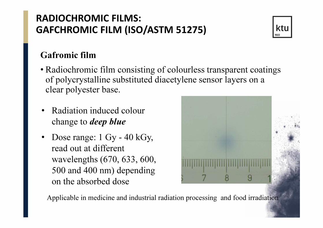
Gafromic film
• Radiochromic film consisting of colourless transparent coatings of polycrystalline substituted diacetylene sensor layers on a clear polyester base.
Applicable in medicine and industrial radiation processing and food irradiation
• Radiation induced colour
change to deep blue
• Dose range: 1 Gy - 40 kGy,
read out at different
wavelengths (670, 633, 600,
500 and 400 nm) depending
on the absorbed dose

RADIOCHROMIC FILMS: (ISO/ASTM 51275)
• Spectrophotometric readout;
Gafchromic GEX(B3) FWT
Dose range, kGy: 3 – 150 3 – 150 0.001 - 40
Wavelength, nm: 554 510, 605 670, 633, 580, 400
• Stability: heat treatment after irradiation; packaging (UV);

SYSTEMS BASED ON OPTICAL ABSORPTION(TETRAZOLIUM SALTS)
Tetrazolium salts :
Heterocyclic organic compounds, yielding highly coloured
water insoluble formazans due to radiolytic reduction
Compound / Product λmax. Dose range:
• tetrazolium violet (TV) 525 nm 0.01 – 30 kGy
• tetrazolium red (TTC) 490 nm 0.01 – 100 kGy
• tetrazolium blue (TB) 520 nm 0.01 – 10 kGy
• nitro blue tetrazolium (NBT) 522 nm, 0.01 – 25 kGy
612 nm

DOSIMETRY APPLICATION OF NBT SOLUTION
• Dose dependence of monoformazan (522 nm) and diformazan (612 nm) radiolysis products formed in aqueous NBT solution
612 nm 522 nm

OSL: THE SUNNA DOSIMETER
The Sunna dosimeter: LiF dispersed uniformly in PE matrix
• Principle:
� Formation of colour centers (F-,
M-, N-, R centers) = (discrete
optical absorption bands) in the
near UV and visible spectrum
due to irradiation;
� Excitation of the irradiated
crystal with light at the
wavelength of the colour centre
absorption;
� Characteristic luminescence at a
significantly higher wavelength.

OSL: THE SUNNA DOSIMETER
• Red, green or IR OSL or UV absorption is used for dosimetry
Dose range:
The Sunna film is applied in both gamma and electron processing for dose
distribution measurements, as well as for routine process control.
• 5 – 100 kGy , evaluation of UV
absorbance at 240 nm;
• 200 Gy – 250 kGy, evaluation of
green OSL at 530 nm;
• 10 Gy – 10 kGy, evaluation of
IR OSL at 670 nm and 1100 nm

DOSIMETRY SYSTEMS IN RADIATION PROCESSING
Transfer standard systems:
• Intermediary system with high metrological qualities, suitablefor transferring dose information from an accredited/standard laboratory to an irradiation facility to establish traceability (comparing absorbed dose measurements)⇒dosimetry intercomparison exercise;
• These systems require calibration;
• Dosimetry systems:
- alanine;
- ethanol-chlorobenzene (ECB);
- potassium dichromate;
- ceric-cerous,

DOSIMETRY SYSTEMS IN RADIATION PROCESSING
Routine systems:
• Dosimetry systems used in radiation processing facilities for absorbed dose mapping and process monitoring;
• Systems, capable of giving reproducible signals;
• These systems require calibration;
• Dosimeter systems:
- Perspex (red-, amber-, Gammachrome);
- Radiochromic films (FWT-60, B3 - Gex,
Gafchromic, Sunna);
- ECB, ceric-cerous solutions;
- Process calorimeters (water, graphite, polystyrene);


ENVIRONMENTAL EFFECTS ON DOSIMETRY SYSTEMS

NEW APPROACHES – NOVEL DOSIMETRY SYSTEMS
• Requirements:
• New technologies (environmental processes, food irradiation at low temperatures, anthrax, pharmaceuticals, X-ray technologies, high dose control);
• Achieved by:
• Improvement of existing dosimetry systems;
• Introduction of new systems;

NEW APPROACHES – NOVEL DOSIMETRY SYSTEMS
• New type low energy calorimeters
0.08 – 0.12 MeV and 1.5 – 4 MeV systems
• Systems based on conductivity analysis
Alanine solution, conducting plastics
• Systems based on colour change
B3, FWT-60, GafChromic and Tetrazolium films
• Systems based on fluorimetry analysis
- Sunna film (green and IR OSL; OD)

SYSTEMS BASED ON CONDUCTIVITY EVALUATION
• Aqueous – alanine solution (1 – 100 kGy)
• Polyaniline based polymer composites
(5 – 150 kGy)
(in research phase)

SYSTEMS BASED ON FLUORIMETRY
Principles:
• Absorbed energy is emitted as fluorescent light due to optical excitation (OSL – optically stimulated luminescence);
• Fluorescence appears micro- or nanoseconds after excitation;
Advantages:
• Wide dynamic range;
• High sensitivity;
• Passive and real time dosimetry;
• Variable geometries;
• Inexpensive detectors;
• Multipurpose applications (medical diagnostic, radiation processing, radiation protection, space studies, etc);

SYSTEMS BASED ON FLUORIMETRY
Application possibilities:
• Radiation induced decay of originally fluorescent molecules (anthracene, fluorescein derivatives, etc);
• Appearance of radiation induced fluorescence due to formation of new fluorescent radiolysis products (Sunna film);

DOSE MAPPING: RISØSCAN

NOVEL DOSIMETRY SYSTEMS

PERSONAL DOSIMETRY
A big variety of different dosimeters:
- Film dosimeter
- TLD
-OSL
-Semiconductor devices

LUMINESCENCE DOSIMETRY
• There are two types of luminescence:
- fluorescence
- phosphorescence
• The difference depends on the time delay between the stimulation and the emission of light:
Fluorescence has a time delay between 10-10 to 10-8 s
Phosphorescence has a time delay exceeding 10-8 s

LUMINESCENCE DOSIMETRY
• Upon radiation, free electrons and holes are produced
• In a luminescence material, there are so-called storage traps
• Free electrons and holes will either recombine immediately or become trapped (at any energy between valence and conduction band)
Principle:

LUMINESCENCE DOSIMETRY
• Upon stimulation, the probability increases for the electrons to be raised to the conduction band …
• and to release energy (light) when they combine with a positive hole (needs an impurity of type 2)
Principle (cont.)

LUMINESCENCE DOSIMETRY
• The process of luminescence can be accelerated with a suitable excitation in the form of heat or light.
• If the exciting agent is heat, the phenomenon is known as
thermoluminescence
• When used for purposes of dosimetry, the material is called a
• thermoluminescent (TL) material
• or a thermoluminescent dosimeter (TLD).

LUMINESCENCE DOSIMETRY
• The process of luminecence can be accelerated with a suitable excitation in the form of heat or light.
• If the exciting agent is light, the phenomenon is referred to as
optically stimulated luminescence (OSL)

THERMOLUMINESCENT DOSIMETER SYSTEMS
• TL dosimeters most commonly used in medical applications are (because of their tissue equivalence):
• LiF:Mg,Ti
• LiF:Mg,Cu,P
• Li2B4O7:Mn
• Other TLDs are (because of their high sensitivity):
• CaSO4:Dy
• Al2O3:C
• CaF2:Mn
• TLDs are available in various forms (e.g., powder, chip, rod, ribbon, etc.).
Before use, TLDs have to be annealed to erase any residual signal.

The TL intensity emission is a function of the TLD temperature T
TLD glow curveor thermogram
Keeping the heating rate constant makes the temperature T proportional to time t and so the TL intensity can be plotted as a function of t.
THERMOLUMINESCENT DOSIMETER SYSTEMS

THERMOLUMINESCENT DOSIMETER SYSTEMS
• The main dosimetric peak of the LiF:Mg,Ti glow curve is between 180° and 260°C; this peak is used for dosimetry.
• TL dose response is linear over a wide range of doses used in radiotherapy, however:
• In higher dose region it increases exhibiting supralinearbehaviour;
• at even higher doses it saturates’
• To derive the absorbed dose from the TL-reading after calibration, correction factors have to be applied:
• energy correction
• fading
• dose-response non-linearity corrections

THERMOLUMINESCENT DOSIMETRY SYSTEM

OPTICALLY STIMULATED LUMINESCENCE SYSTEMS
• Optically-stimulated luminescence (OSL) is based on a principle similar to that of the TLD. Instead of heat, light (from a laser) is used to release the trapped energy in the form of luminescence.
• OSL is a novel technique offering a potential for in vivo dosimetry in radiotherapy.
• A further novel development is based on the excitation by a pulsed laser (POSL)
• The most promising material is Al2O3:C
• To produce OSL, the chip is excited with a laser light through an optical fiber and the resulting luminescence (blue light) is carried back in the same fiber, reflected through a 90° by a beam-splitter and measured in a photomultiplier tube.

OPTICALLY STIMULATED LUMINESCENCE SYSTEMS
Crystal: 0.4 mm x 3 mm Optical fiber read out

Simple OSL system
Sample
Heater Strip
OSL
PMT
Detection filter
Focusing lens
Stimulation filter
Stimulation light source

Conceptual Energy Diagram After Irradiation
Luminescence Centers
Dosimetric Traps

Optically Stimulated Luminescence (OSL)
Luminescence Centers
Dosimetric Traps

Thermoluminescence Dosimetry (TLD)
Luminescence Centers
Dosimetric Traps

TL / OSL

ADVANTAGES OF USING OSL OVER TL
1) OSL is normally measured at room temperature and is
thus a non-destructive method (e.g. TL suffers from
thermal quenching)
2) OSL is theoretically more sensitive than TL
3) Parts of the OSL signal can be measured multiple times
on same sample (short shine). TL requires total erasing
of signal
4) The TL signal can usually be measured after OSL
readout on same sample (not same traps)
5) Heating a sample (TL) will release luminescence from
the whole sample

SEMICONDUCTOR DOSIMETRY
• A silicon diode dosimeter is a positive-negative junction diode.
• The diodes are produced by taking n-type or p-type silicon and counter-doping the surface to produce the opposite type material.
Both types of diodes are commercially
available, but only the p-Si type is suitable for
radiotherapy dosimetry, since it is less affected
by radiation damage and has a much smaller
dark current.
These diodes are referred to
as n-Si or p-Si dosimeters,
depending upon the base
material.
SILICON DIODE DOSIMETRY SYSTEMS
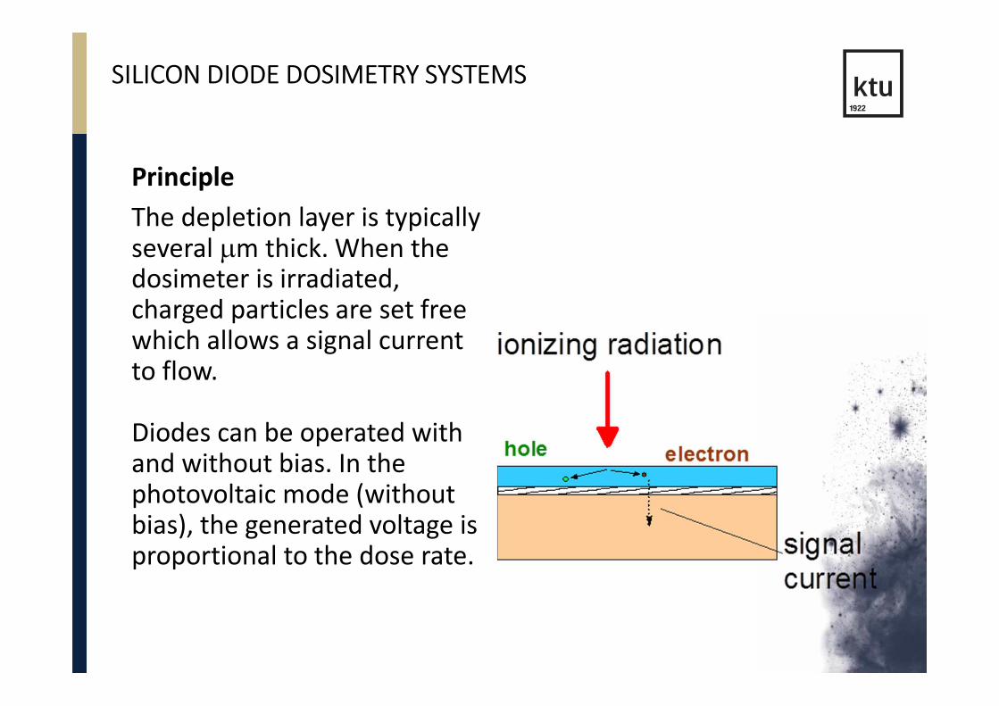
Principle
The depletion layer is typically several µm thick. When the dosimeter is irradiated, charged particles are set free which allows a signal current to flow.
Diodes can be operated with and without bias. In the photovoltaic mode (without bias), the generated voltage is proportional to the dose rate.

SILICON DIODE DOSIMETRY SYSTEMS

MOSFET DOSIMETRY SYSTEMS
A MOSFET dosimeter is a Metal-Oxide Semiconductor Field
Effect Transistor.
Physical Principle:
• Ionizing radiation generates charge carriers in the Si oxide.
• The charge carries moves towards the silicon substrate
where they are trapped.
• This leads to a charge buildup causing a change in threshold
voltage between the gate and the silicon substrate.
substratee.g., glass
encapsulation
Si substrate
n-type (thickness 300 µm)
SiO
Al electrode (gate)

MOSFET DOSIMETRY SYSTEMS
Measuring Principle:
• MOSFET dosimeters are based on the measurement of the
threshold voltage, which is a linear function of absorbed dose.
• The integrated dose may be measured during or after
irradiation.
Characteristics:
• MOSFETs require a connection to a bias voltage during irradiation.
• They have a limited lifespan.
• The measured signal depends on the history of the MOSFET
dosimeter.

MOSFET DOSIMETRY SYSTEMS
Advantages
• MOSFETs are small
• Although they have a
response dependent on
radiation quality, they do
not require an energy
correction for mega-
voltage beams.
• During their specified
lifespan they retain
adequate linearity.
• MOSFETs exhibit only
small axial anisotropy
(±2% for 360º).
Disadvantages
• MOSFETs are sensitive to
changes in the bias
voltage during irradiation
(it must be stable).
• Similarly to diodes, they
exhibit a temperature
dependence.

Thank you for your attention!
Joint innovative training and teaching/
learning program in enhancing development
and transfer knowledge of application of
ionizing radiation in materials processing