5 steps in stick welding
TRANSCRIPT
7/29/2019 5 Steps in Stick Welding
http://slidepdf.com/reader/full/5-steps-in-stick-welding 1/7
Five Steps To Improving Your Stick Welding Technique
For many people, especially to those who are new to it or perhaps who don’t weld every day, Stick (SMAW—shieldedmetal arc welding) is one of the more difficult processes to learn. Experienced welders who can pick up a stinger, popan electrode in and lay down great welds time after time can inspire great awe in the rest of us. They make it lookeasy.
The rest of us may struggle with it, though. And we don’t have to, not if we pay attention to five basic elements of our technique: Current setting, Length of arc, Angle of electrode, Manipulation of electrode and Speed of travel—or CLAMS, for short. Properly addressing these five basic areas can improve your results.
PrepareWhile Stick welding may be the most forgiving process on dirty or rusty metal, don’t use that as an excuse for notproperly cleaning the material. Use a wire brush or grinder to remove dirt, grime or rust from the area to be welded. If you don’t, you’re hurting your chances to make a good weld the first time. Unclean conditions can lead to cracking,porosity, lack of fusion or inclusions. While you’re at it, make sure you have a clean spot for the work clamp. A good,solid electrical connection is important to maintain arc quality.
Then position yourself so you have good view of the weld puddle. For the best view, keep your head off to the sideand out of the smoke so you can be sure you’re welding in the joint and keeping the arc on the leading edge of thepuddle. Make sure your stance will allow you to comfortably support and manipulate the electrode.
CLAMSBringing all the CLAMS points (Current setting, Length of arc, Angle of electrode, Manipulation of the electrode, andSpeed of travel) together may seem like a lot to think about while welding, but it becomes second nature withpractice. Don’t get discouraged! There is a learning curve with Stick welding, which many believe got its namebecause when learning how to weld, everyone sticks the electrode to the workpiece.
Current setting: The electrode you select will determine whether your machine should be set up in DC positive, DCnegative or AC. Make sure you have it set correctly for your application. (Electrode positive provides about 10 percentmore penetration at a given amperage than AC, while DC straight polarity, electrode negative, welds thinner metalsbetter.)
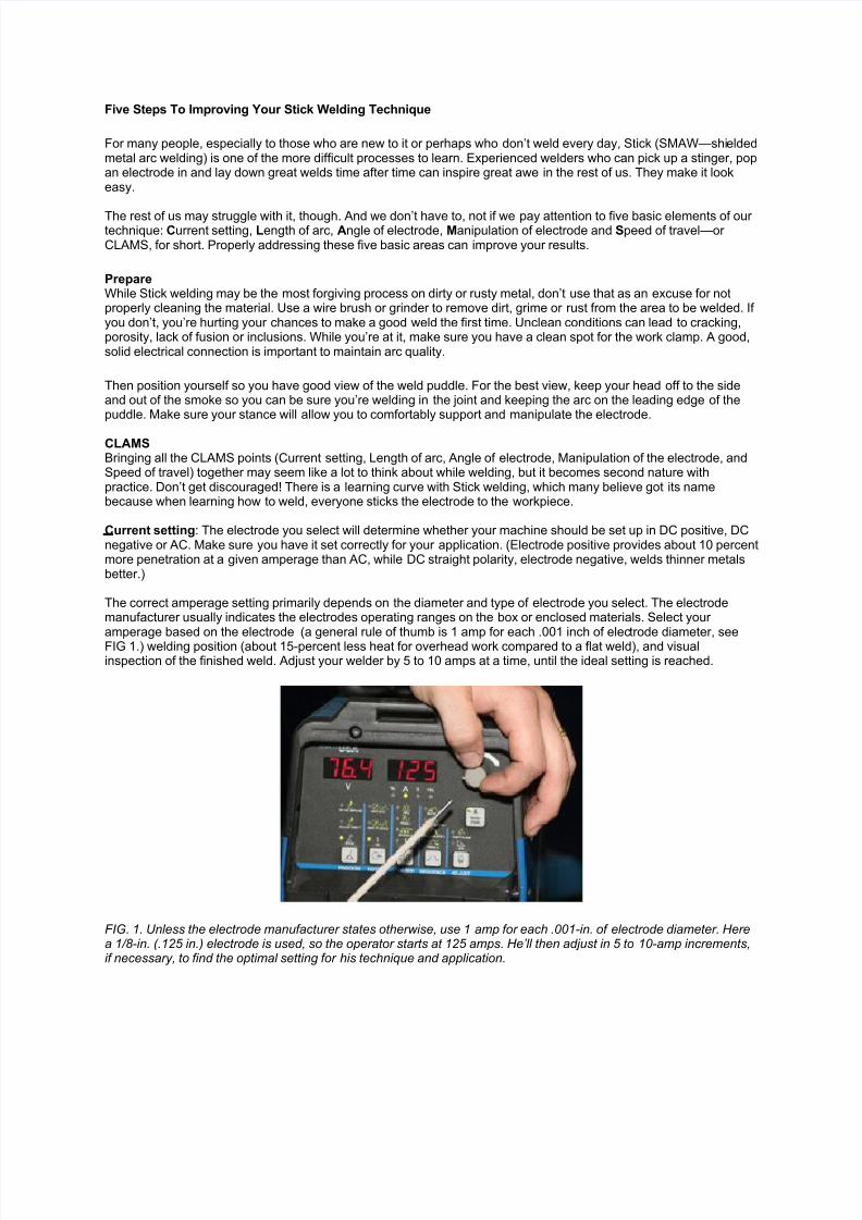
The correct amperage setting primarily depends on the diameter and type of electrode you select. The electrodemanufacturer usually indicates the electrodes operating ranges on the box or enclosed materials. Select your amperage based on the electrode (a general rule of thumb is 1 amp for each .001 inch of electrode diameter, see
FIG 1.) welding position (about 15-percent less heat for overhead work compared to a flat weld), and visualinspection of the finished weld. Adjust your welder by 5 to 10 amps at a time, until the ideal setting is reached.
FIG. 1. Unless the electrode manufacturer states otherwise, use 1 amp for each .001-in. of electrode diameter. Herea 1/8-in. (.125 in.) electrode is used, so the operator starts at 125 amps. He’ll then adjust in 5 to 10-amp increments,if necessary, to find the optimal setting for his technique and application.
7/29/2019 5 Steps in Stick Welding
http://slidepdf.com/reader/full/5-steps-in-stick-welding 2/7
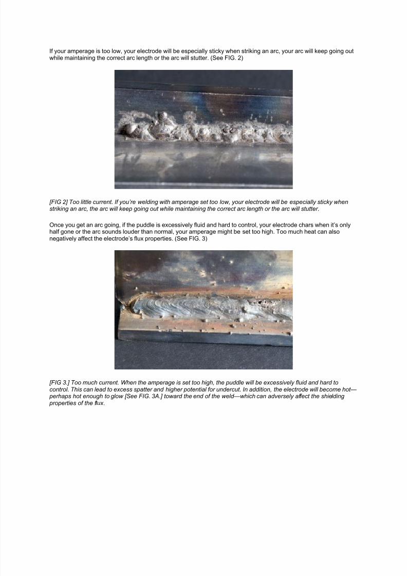
If your amperage is too low, your electrode will be especially sticky when striking an arc, your arc will keep going outwhile maintaining the correct arc length or the arc will stutter. (See FIG. 2)
[FIG 2] Too little current. If you’re welding with amperage set too low, your electrode will be especially sticky whenstriking an arc, the arc will keep going out while maintaining the correct arc length or the arc will stutter.
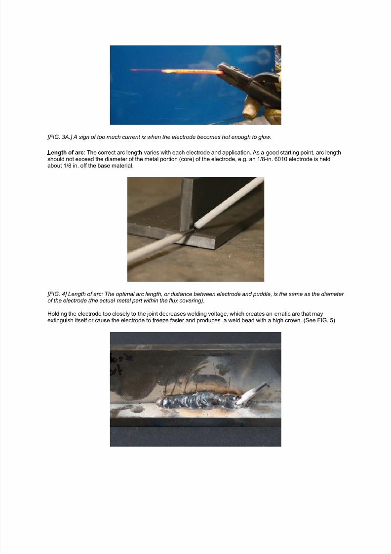
Once you get an arc going, if the puddle is excessively fluid and hard to control, your electrode chars when it’s onlyhalf gone or the arc sounds louder than normal, your amperage might be set too high. Too much heat can alsonegatively affect the electrode’s flux properties. (See FIG. 3)
[FIG 3.] Too much current. When the amperage is set too high, the puddle will be excessively fluid and hard tocontrol. This can lead to excess spatter and higher potential for undercut. In addition, the electrode will become hot—
perhaps hot enough to glow [See FIG. 3A.] toward the end of the weld—which can adversely affect the shielding
properties of the flux .
7/29/2019 5 Steps in Stick Welding
http://slidepdf.com/reader/full/5-steps-in-stick-welding 3/7
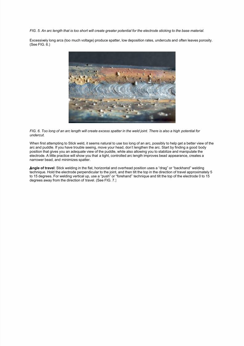
[FIG. 3A.] A sign of too much current is when the electrode becomes hot enough to glow.
Length of arc: The correct arc length varies with each electrode and application. As a good starting point, arc lengthshould not exceed the diameter of the metal portion (core) of the electrode, e.g. an 1/8-in. 6010 electrode is heldabout 1/8 in. off the base material.
[FIG. 4] Length of arc: The optimal arc length, or distance between electrode and puddle, is the same as the diameter of the electrode (the actual metal part within the flux covering).
Holding the electrode too closely to the joint decreases welding voltage, which creates an erratic arc that mayextinguish itself or cause the electrode to freeze faster and produces a weld bead with a high crown. (See FIG. 5)
7/29/2019 5 Steps in Stick Welding
http://slidepdf.com/reader/full/5-steps-in-stick-welding 4/7
FIG. 5. An arc length that is too short will create greater potential for the electrode sticking to the base material.
Excessively long arcs (too much voltage) produce spatter, low deposition rates, undercuts and often leaves porosity.(See FIG. 6.)
FIG. 6. Too long of an arc length will create excess spatter in the weld joint. There is also a high potential for undercut.
When first attempting to Stick weld, it seems natural to use too long of an arc, possibly to help get a better view of thearc and puddle. If you have trouble seeing, move your head, don’t lengthen the arc. Start by finding a good bodyposition that gives you an adequate view of the puddle, while also allowing you to stabilize and manipulate theelectrode. A little practice will show you that a tight, controlled arc length improves bead appearance, creates anarrower bead, and minimizes spatter.
Angle of travel: Stick welding in the flat, horizontal and overhead position uses a “drag” or “backhand” weldingtechnique. Hold the electrode perpendicular to the joint, and then tilt the top in the direction of travel approximately 5to 15 degrees. For welding vertical up, use a “push” or “forehand” technique and tilt the top of the electrode 0 to 15
degrees away from the direction of travel. (See FIG. 7.)
7/29/2019 5 Steps in Stick Welding
http://slidepdf.com/reader/full/5-steps-in-stick-welding 5/7
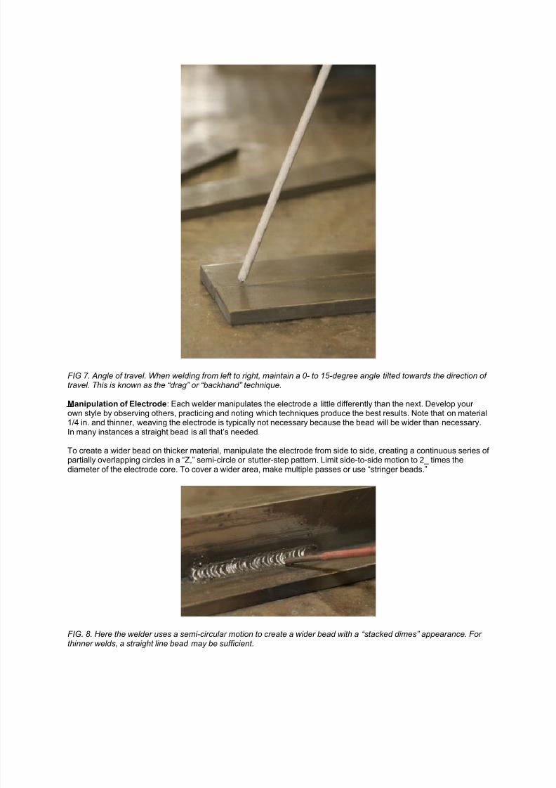
FIG 7. Angle of travel. When welding from left to right, maintain a 0- to 15-degree angle tilted towards the direction of travel. This is known as the “drag” or “backhand” technique.
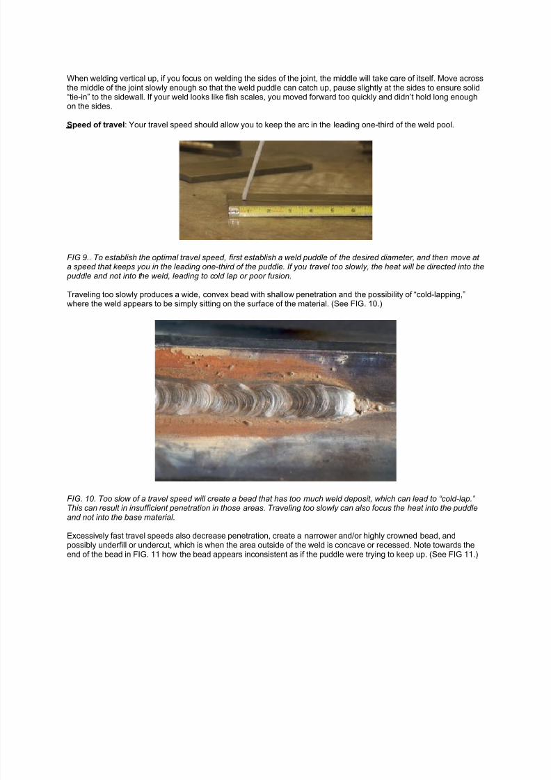
Manipulation of Electrode: Each welder manipulates the electrode a little differently than the next. Develop your
own style by observing others, practicing and noting which techniques produce the best results. Note that on material1/4 in. and thinner, weaving the electrode is typically not necessary because the bead will be wider than necessary.In many instances a straight bead is all that’s needed.
To create a wider bead on thicker material, manipulate the electrode from side to side, creating a continuous series of partially overlapping circles in a “Z,” semi-circle or stutter-step pattern. Limit side-to-side motion to 2_ times thediameter of the electrode core. To cover a wider area, make multiple passes or use “stringer beads.”
FIG. 8. Here the welder uses a semi-circular motion to create a wider bead with a “stacked dimes” appearance. For thinner welds, a straight line bead may be sufficient.
7/29/2019 5 Steps in Stick Welding
http://slidepdf.com/reader/full/5-steps-in-stick-welding 6/7
When welding vertical up, if you focus on welding the sides of the joint, the middle will take care of itself. Move acrossthe middle of the joint slowly enough so that the weld puddle can catch up, pause slightly at the sides to ensure solid“tie-in” to the sidewall. If your weld looks like fish scales, you moved forward too quickly and didn’t hold long enoughon the sides.
Speed of travel: Your travel speed should allow you to keep the arc in the leading one-third of the weld pool.
FIG 9.. To establish the optimal travel speed, first establish a weld puddle of the desired diameter, and then move at a speed that keeps you in the leading one-third of the puddle. If you travel too slowly, the heat will be directed into the
puddle and not into the weld, leading to cold lap or poor fusion.
Traveling too slowly produces a wide, convex bead with shallow penetration and the possibility of “cold-lapping,”where the weld appears to be simply sitting on the surface of the material. (See FIG. 10.)
FIG. 10. Too slow of a travel speed will create a bead that has too much weld deposit, which can lead to “cold-lap.” This can result in insufficient penetration in those areas. Traveling too slowly can also focus the heat into the puddleand not into the base material.
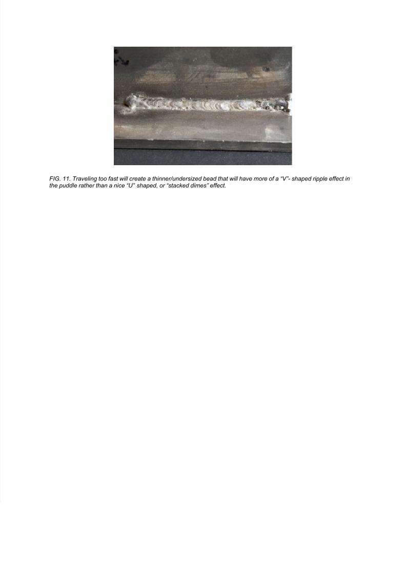
Excessively fast travel speeds also decrease penetration, create a narrower and/or highly crowned bead, and
possibly underfill or undercut, which is when the area outside of the weld is concave or recessed. Note towards theend of the bead in FIG. 11 how the bead appears inconsistent as if the puddle were trying to keep up. (See FIG 11.)
7/29/2019 5 Steps in Stick Welding
http://slidepdf.com/reader/full/5-steps-in-stick-welding 7/7
FIG. 11. Traveling too fast will create a thinner/undersized bead that will have more of a “V”- shaped ripple effect inthe puddle rather than a nice “U” shaped, or “stacked dimes” effect.