50 amp rv power pedestal tester - heavy · a few years ago, i built a 50 amp power pedestal tester...
TRANSCRIPT

50 Amp RV Power
Pedestal Tester
© Steve Dixon 2014

A few years ago, I built a 50 Amp Power Pedestal Tester that would test an RV Power Pedestal under a no load condition. It would check for proper voltage on both legs, check for proper wiring like an open ground for example, and it would check that leg 1 and leg 2 were in fact separate and not tied together. This worked fine under a no load condition, but sometimes, problems don’t show up until it’s under a heavy load.
2

Recently, I have come across power pedestals that checked normal with no load, but as soon as a load was place on them, either one or both legs would drop off. So I decided that I needed a new and improved pedestal tester that would be able to test under a no load as well as a loaded condition. I thought of various ways to put an electrical load on it. Most everything I thought of was either impractical, or very expensive. Then I thought of electric water heater elements. They are compact, inexpensive, and can put on a pretty good load. I could use two 2000 Watt elements per leg giving about a 34 Amp load on each leg.
Heat dissipation was my next concern. Water is the first obvious answer, but I didn’t want it to freeze in the winter, and the boiling is fairly low creating excess pressure in a sealed container. I considered various other substances for heat sinks, but finally settled on an 80 / 20 mix of antifreeze and water. That raises the boiling point to about 280F and the freezing point is about -20F.
The next decision is what to use to hold the heating elements and the antifreeze. My first thought was to go to my local metal fabricator and get a piece of 6” aluminum pipe, weld plate to both ends, then drill and tap for the heating elements. Expensive! My next thought was a piece of 6” PVC pipe and a couple of caps. Price not too bad, but then I would need to buy a 1” NPT Tap for $83. Not gonna happen for just four holes. So as I’m walking through Lowes, I saw an empty one gallon paint can. Perfect! The price was right and it’s easy to work with.
Now I need something to put it all in. I thought of various plastic containers big enough for the paint can, but everything I found that was big enough for the paint can, was just too big to be practical. Then at Walmart, I found this Toolbox.
I drilled a hole in the side using a step drill for the through hole fitting. A rubber grommet would have worked, but I already had the fitting.
3

4

Next I got a 6 ft, 50 Amp, Pigtail. Stripped off about 2 ft and inserted it through the fitting into the toolbox.
5
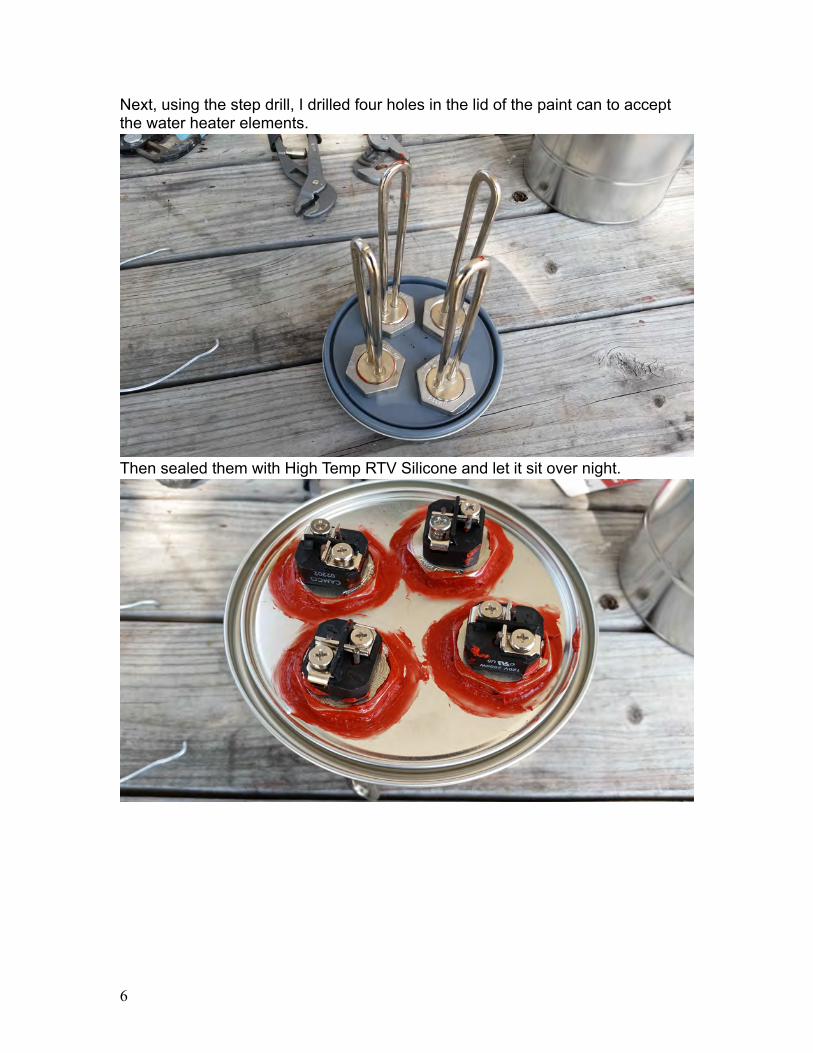
Next, using the step drill, I drilled four holes in the lid of the paint can to accept the water heater elements.
Then sealed them with High Temp RTV Silicone and let it sit over night.
6

I cut and drill holes to accept the meters and NEON lights.
And then wired together all the NEON lights. To make wiring the rest of it up easier later, I used colored heat shrink so that it would be easy to identify Leg 1, Leg 2, Neutral and Ground. Wiring the Neons will be detailed later.
7

To measure Amperage, a transformer coil is slipped over each of the two HOT wires. (Black and Red)
Next comes the 40 Amp contactor (Relay). In the first version of this, I had both Leg 1 and 2 going through the same relay. This would allow me to test a pedestal under a load with both legs, but not each leg individually. The upgraded version of this uses two relays, one for each leg and are individually switched. This allows me to test either no load, Leg 1 only, Leg 2 only, or both together. The individual leg testing is better at revealing some of the more common pedestal problems.
8

Having let the sealant on the water heater elements cure over night, fill the paint can full with an 80 / 20 mix of antifreeze / water. Place the lid on the can leaving little or no air in the can. Be sure the can lid is firmly in place.
Now we wire up the water heater elements. Leg 1 and Leg 2 are each wired to two heating elements in parallel. The Leg 1 Hot (Black #6 wire) will go to one of the heater elements. The Neutral (White #8 wire) will go to the same element. The second heating element on Leg 1 is wired with #12 wire. From the same screw that the Black #6 wire is connected, run a #12 wire to the next heating element. Now from the screw that the White #8 wire is connected, run a #12 wire to that same heating element.
For Leg 2, we will start by running a piece of White #8 wire from the first heating element to one of the unused heating elements. Then connect the Leg 2 Hot (Red #6 wire) to that same element. The last heating element also gets wired with #12. Run one wire from the same screw as the Red #6 wire to the last element and now from the screw that the White #8 wire is connected, run a #12 wire to the last heating element.
One last wire. From any of the Neutral wires on one of the heating elements, it doesn’t matter which one, run a #12 wire to the coil connector on one of the Relays. That’s the one on the side of the relay pictured above. It doesn’t matter which post you connect to. Then continue that wire to the same position other Relay.
9
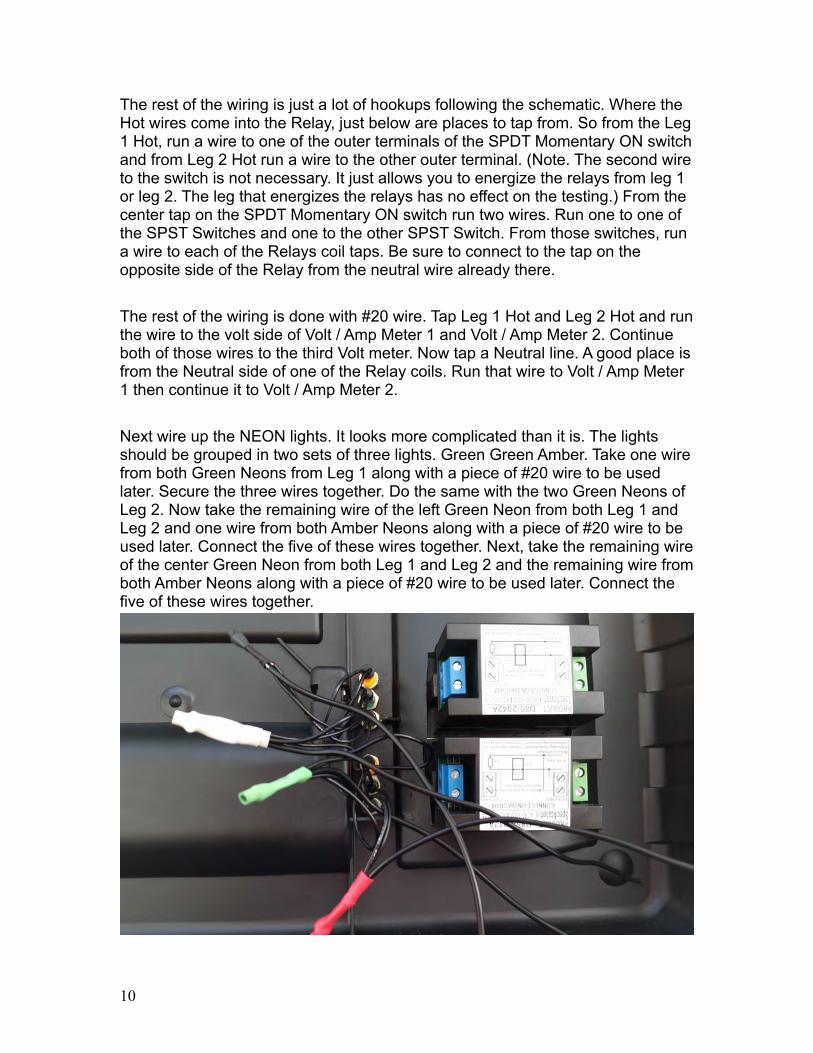
The rest of the wiring is just a lot of hookups following the schematic. Where the Hot wires come into the Relay, just below are places to tap from. So from the Leg 1 Hot, run a wire to one of the outer terminals of the SPDT Momentary ON switch and from Leg 2 Hot run a wire to the other outer terminal. (Note. The second wire to the switch is not necessary. It just allows you to energize the relays from leg 1 or leg 2. The leg that energizes the relays has no effect on the testing.) From the center tap on the SPDT Momentary ON switch run two wires. Run one to one of the SPST Switches and one to the other SPST Switch. From those switches, run a wire to each of the Relays coil taps. Be sure to connect to the tap on the opposite side of the Relay from the neutral wire already there.
The rest of the wiring is done with #20 wire. Tap Leg 1 Hot and Leg 2 Hot and run the wire to the volt side of Volt / Amp Meter 1 and Volt / Amp Meter 2. Continue both of those wires to the third Volt meter. Now tap a Neutral line. A good place is from the Neutral side of one of the Relay coils. Run that wire to Volt / Amp Meter 1 then continue it to Volt / Amp Meter 2.
Next wire up the NEON lights. It looks more complicated than it is. The lights should be grouped in two sets of three lights. Green Green Amber. Take one wire from both Green Neons from Leg 1 along with a piece of #20 wire to be used later. Secure the three wires together. Do the same with the two Green Neons of Leg 2. Now take the remaining wire of the left Green Neon from both Leg 1 and Leg 2 and one wire from both Amber Neons along with a piece of #20 wire to be used later. Connect the five of these wires together. Next, take the remaining wire of the center Green Neon from both Leg 1 and Leg 2 and the remaining wire from both Amber Neons along with a piece of #20 wire to be used later. Connect the five of these wires together.
10
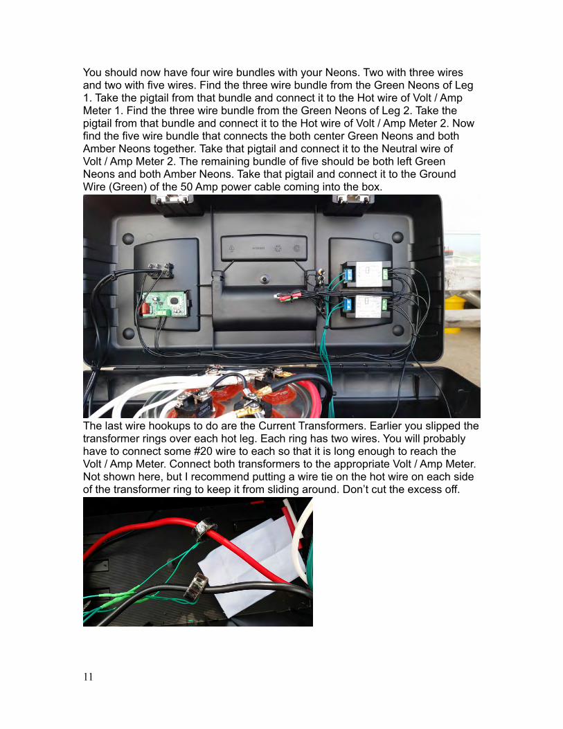
You should now have four wire bundles with your Neons. Two with three wires and two with five wires. Find the three wire bundle from the Green Neons of Leg 1. Take the pigtail from that bundle and connect it to the Hot wire of Volt / Amp Meter 1. Find the three wire bundle from the Green Neons of Leg 2. Take the pigtail from that bundle and connect it to the Hot wire of Volt / Amp Meter 2. Now find the five wire bundle that connects the both center Green Neons and both Amber Neons together. Take that pigtail and connect it to the Neutral wire of Volt / Amp Meter 2. The remaining bundle of five should be both left Green Neons and both Amber Neons. Take that pigtail and connect it to the Ground Wire (Green) of the 50 Amp power cable coming into the box.
The last wire hookups to do are the Current Transformers. Earlier you slipped the transformer rings over each hot leg. Each ring has two wires. You will probably have to connect some #20 wire to each so that it is long enough to reach the Volt / Amp Meter. Connect both transformers to the appropriate Volt / Amp Meter. Not shown here, but I recommend putting a wire tie on the hot wire on each side of the transformer ring to keep it from sliding around. Don’t cut the excess off.
11

It should be all wired up now and time to test.
Find a vacant 50 Amp Power Pedestal. Turn off the circuit breaker. Plug in the cord and turn on the circuit breaker. You should have indications similar to this.
Leg 1 and Leg 2 should be reading about 120 Volts each and the combined voltage be the sum of Leg 1 and Leg 2 give or take a volt. In this case 241 Volts. The Amp reading for both Leg 1 and Leg 2 should be 0 Amps. All four Green Neons should be on and both Amber Neons should be off.The next picture is the tester under a load. A slight drop in voltage is normal.
12

In this case, each leg is 116 Volts and the combined voltage is 232 Volts. Amperage is a little over 30 Amps each leg. The Neons still indicate normal.
All of the photos here are of the first version of the tester. The newer version (no photos yet) has two additional switches as indicated in the schematic. This allows for testing each leg individually. This will often cause a problem to show up that a balanced load may not. So on the new version, you can energize the heating elements on one leg while leaving the other leg live yet unloaded. The voltages should still remain close to the same. Amperage should be 30 to 35 on one leg and zero on the other. If the voltage goes UP on one leg and down on the other, this indicates a problem that can cause serious damage to your rig and that power pedestal should not be used!
Caution! Do not run the load test for more than about 1 minute. Remember, you have 8000 Watts directly heating one gallon of fluid. If it boils, the can may rupture causing severe burns. Use this at your own risk.
Caution! Electricity can be DANGEROUS! If not handled properly, it can KILL YOU! If you do not understand electricity or are not sure of your skill set dealing with electricity, do not build this. Get some competent help. Build and use this at your own risk. This is a device I built for myself and I offer no guarantees that it will work for you.
13

Parts List – Many of the parts can be found at Lowes, Home Depot, Radio Shack etc. The highlighted words are clickable links to the parts that you may not find locally. The links should work in Adobe Reader. They may not work in some other PDF viewers.
2 - Packard Contactor 2 Pole 40 Amps 120 Coil Voltage
1 - Digital Voltmeter
2 - Digital Voltmeter Ammeter
4 - 2000W Water Heater Element
4 - Stainless Steel Hex Locknut, 1" NPT Female
4 - 120 -Volt Neon Green Lamp
2 - 120 -Volt Neon Amber Lamp
1 – SPDT (Single Pole Double Throw) or DPDT (Double Pole Double Throw) Momentary ON Switch
2 – SPST (Single Pole Single Throw) Switch
1 - Stanley STST19005 19-Inch Tool Box
1 - 1-gal. Metal Paint Bucket and Lid
1 - 50-Amp Range Power Supply Cord
1 - Through Fitting
1 - High Temperature RTV Silicone
Assorted Heat Shrink Tubing
Assorted Wire Ties
Assorted Wire Connectors
12AWG and 20AWG Stranded Wire
14

15