50 ways to use the field kit - koma elektronik · 3. 50 ways to use the field kit 34 3.1 in the...
TRANSCRIPT
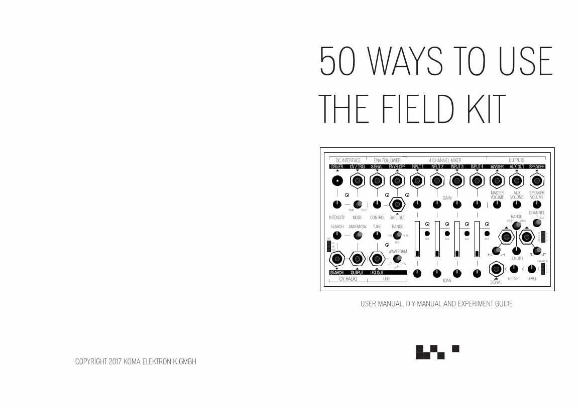
50 WAYS TO USE THE FIELD KIT
USER MANUAL, DIY MANUAL AND EXPERIMENT GUIDE
COPYRIGHT 2017 KOMA ELEKTRONIK GMBH

3
Madewithlove
inBerlin
The KOMA Elektronik Team
♥
1. Introduction 6
2. User Manual 7
2.1 Getting Started 7
2.2 Function Overview 7
2.2.1 4 Channel Mixer 8 2.2.2 Outputs 11 2.2.3 CV Radio 14
2.2.3.1 Usage Of Antennas 16 2.2.3.2 CV Radio Tuning Ranges 17
2.2.4 DC Interface 18 2.2.5 Envelope Follower 22 2.2.6 Low Frequency Oscillator 25 2.2.7 Signal Interface 28 2.2.7.1 Switch Interface 29 2.2.7.2 Sensor Interface 30 2.2.8 Field Kit in A Eurorack System 32
2.2.8.1 Power 32 2.2.8.2 Panel 33
Table of Contents
3. 50 Ways to Use the Field Kit 34 3.1 In the Kitchen 34
3.2 In Your Studio 39
3.3 On Stage 44 3.4 With Friends 49
3.5 With Sensors 54
3.6 At an Art Gallery 59
3.7 The Field Kit Lid 64
3.8 A Variety Of Spices 69
3.9 Koma Favourites 74
4.0 All Other Patches 79
4. DIY Manual 84
5. Frequently Asked Questions 90 6. Warranty 93
7. Imprint 94
8. Who Made The Field Kit Possible 95
9. Glossary 98
10. Patch Sheets 104
Table of Contents
6
Berlin, February 22nd 2017
Thanks so much for purchasing the Field Kit!
After a year of work and a very successfull Kickstarter campaign, we are very happy you finally have your own Field Kit in front of you. We hope this little machine will help you to engage with physical objects in your surroundings and use new sounds in your music. We hope it inspires you to pick up old pieces of gear that have been lying around for a while. We hope the Field Kit brings you fun!
In this book and manual we will show you how to use the Field Kit, how the electronics work, how to build the DIY Version, and we give a bunch of tips on what you can do with it.
For beginners, we added a glossary in the back with used terms and their explanations, so when it gets too technical and you find a word which is underlined, you can find it back in the Glossary. For the more technically advanced users, we added some hacking options to modify the device to your wishes. We also added a bunch of patchsheets in the back. Print them out via our website to write down your own patches, or make copies from this book and do it the analog way!
If you have questions about warranty and what to do if your Field Kit is broken, please check the Warranty section towards the end of this book. If you have a question about your device, please contact us via [email protected] and we will help you get back on your way!
Thanks again for your support, in particular the Kickstarter backers. We could not have done this without you!
Now make some noise!All the best from Berlin,
The KOMA Elektronik Team
1. Introduction
7
2.1 Getting Started
You are reading this text, so you started by opening the manual. Good one! Now, let’s get to playing: Start by unpacking your Field Kit and connect it to power through the included 9V PSU by using the power jack in the backpanel. When mounting the Field Kit in a modular setup, please make sure to read chapter 2.2.8 Field Kit in Eurorack before powering up your system!
Now that your Field Kit is powered up, plug in the Master Out to an amplifier or powered speakers and patch the LFO Out to Channel 1. Flip the Range switch of the LFO to High, open the fader of Channel 1, and make sure the Master Volume is turned up. Now play around with the tune knob and you have your first drone going! From here on, your only limitation is your own imagination!
2. User Manual
2.2 Function Overview
The KOMA Elektronik Field Kit is divided into 7 separate function-al blocks: the 4 Channel Mixer, Outputs, CV Radio, DC Interface, Env(elope) Follower, LFO and Signal Interface. They are designed to operate together as a coherent electro acoustic workstation or alterni-tively with other pieces of music electronics with the ability to use CV (control voltage) signals.
In the following subchapters, we are going to cover the basic opera-tion of the different functional blocks.
8
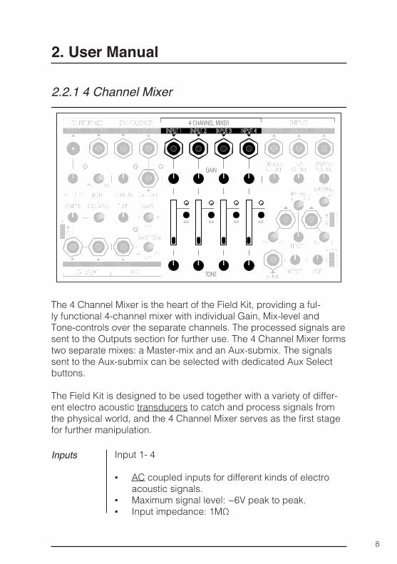
2.2.1 4 Channel Mixer
2. User Manual
Inputs Input 1- 4
▪ AC coupled inputs for different kinds of electro acoustic signals.
▪ Maximum signal level: ~6V peak to peak. ▪ Input impedance: 1MΩ
The 4 Channel Mixer is the heart of the Field Kit, providing a ful-ly functional 4-channel mixer with individual Gain, Mix-level and Tone-controls over the separate channels. The processed signals are sent to the Outputs section for further use. The 4 Channel Mixer forms two separate mixes: a Master-mix and an Aux-submix. The signals sent to the Aux-submix can be selected with dedicated Aux Select buttons.
The Field Kit is designed to be used together with a variety of differ-ent electro acoustic transducers to catch and process signals from the physical world, and the 4 Channel Mixer serves as the first stage for further manipulation.
9
2. User Manual
Control Gain 1 - 4
▪ Lets you amplify the input signal with a settable amount.
▪ Gain range: 1 (fully counterclockwise) - 100 (fully clockwise)
Mix Level 1 – 4
▪ Sets the level of the channel in question.
Aux select 1 - 4
▪ Lets you choose which of the 4 channels gets sent to the Aux-submix.
▪ Signals tapped post-Tone, pre-Level
Tone 1 - 4
▪ Serves as an overall tonal control over the specific channel. By default, it is set up as a tilt-EQ with a center frequency of around 600Hz.
▪ Range: fully CCW: low frequencies (<600Hz) +4.5dB, high frequencies (>600Hz) -6dB/Oct. fully CW: high frequencies +6.5dB, low fre quencies -6dB/Oct.
▪ Check the USER TIP Box at the end of this chapter for information on how to tweak the response of the Tone stage.
10
2. User Manual
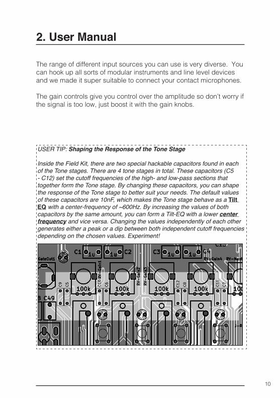
USER TIP: Shaping the Response of the Tone Stage
Inside the Field Kit, there are two special hackable capacitors found in each of the Tone stages. There are 4 tone stages in total. These capacitors (C5 - C12) set the cutoff frequencies of the high- and low-pass sections that together form the Tone stage. By changing these capacitors, you can shape the response of the Tone stage to better suit your needs. The default values of these capacitors are 10nF, which makes the Tone stage behave as a Tilt
EQ with a center-frequency of ~600Hz. By increasing the values of both capacitors by the same amount, you can form a Tilt-EQ with a lower center frequency and vice versa. Changing the values independently of each other generates either a peak or a dip between both independent cutoff frequencies depending on the chosen values. Experiment!
The range of different input sources you can use is very diverse. You can hook up all sorts of modular instruments and line level devices and we made it super suitable to connect your contact microphones.
The gain controls give you control over the amplitude so don’t worry if the signal is too low, just boost it with the gain knobs.
11
2.2.2 Outputs
2. User Manual
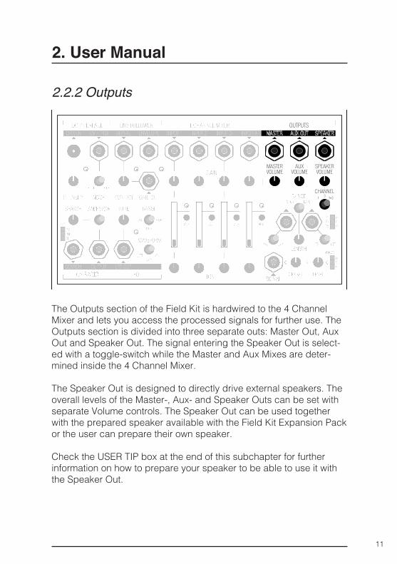
The Outputs section of the Field Kit is hardwired to the 4 Channel Mixer and lets you access the processed signals for further use. The Outputs section is divided into three separate outs: Master Out, Aux Out and Speaker Out. The signal entering the Speaker Out is select-ed with a toggle-switch while the Master and Aux Mixes are deter-mined inside the 4 Channel Mixer.
The Speaker Out is designed to directly drive external speakers. The overall levels of the Master-, Aux- and Speaker Outs can be set with separate Volume controls. The Speaker Out can be used together with the prepared speaker available with the Field Kit Expansion Pack or the user can prepare their own speaker.
Check the USER TIP box at the end of this subchapter for further information on how to prepare your speaker to be able to use it with the Speaker Out.
12
2. User Manual
Inputs
Control
Outputs
Signals from the 4 Channel Mixer
Master Volume
▪ Sets the level of the Master signal.
Aux Volume
▪ Sets the level of the Aux signal.
Speaker Volume
▪ Sets the level of the Speaker output.
Channels
▪ Lets you select the signals sent to the Speaker output.
▪ Options: Channel 1 only, Channel 3 only or both Channel 1 and 3.
▪ The signals sent to the Speaker output are tapped post-fader.
Master
▪ Contains a sub-mix of all the signals mixed down inside the 4 Channel Mixer.
▪ Output Impedance: 1kΩ
Aux
▪ Contains a sub-mix of all the signals sent to the Aux-bus.
▪ The signal to the Aux-bus is tapped pre-fader. ▪ Output Impedance: 1kΩ
13
USER TIP: Preparing a loudspeaker to be used with the Speaker Output
The connection to an external speaker is made via a 3.5mm monophonic minijack connector. To use a speaker of your choice, solder the two wires coming out from the coil of the speaker to the monophonic minijack con-nector so that one wire connects to the tip-terminal and the other to the sleeve-terminal. The polarity of the wiring is not especially important and only affects the phase of the speaker movement.
If you are lucky enough to own multiple Field Kits each with their own ded-icated external speaker, make sure that you connect all the speakers the same way around to avoid phase cancellations (or not, if that’s your goal).
The Speaker output is designed to work best with an 8Ω speaker. It’s safe to use a speaker with a higher impedance (i.e. 16Ω, 32Ω), Impedances lower than 8Ω are not recommended.
2. User Manual
Speaker
▪ Connection to an external speaker. ▪ Maximum output power: 500mW ▪ Recommended loudspeaker impedance: 8Ω ▪ Use the prepared speaker available inside the
Field Kit Accessory Pack or prepare a speaker of your own.
14
2. User Manual
2.2.3 CV Radio
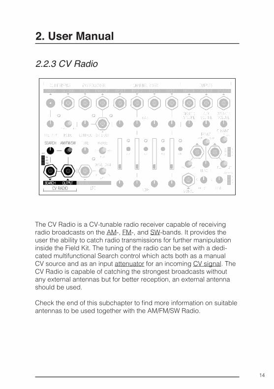
The CV Radio is a CV-tunable radio receiver capable of receiving radio broadcasts on the AM-, FM-, and SW-bands. It provides the user the ability to catch radio transmissions for further manipulation inside the Field Kit. The tuning of the radio can be set with a dedi-cated multifunctional Search control which acts both as a manual CV source and as an input attenuator for an incoming CV signal. The CV Radio is capable of catching the strongest broadcasts without any external antennas but for better reception, an external antenna should be used.
Check the end of this subchapter to find more information on suitable antennas to be used together with the AM/FM/SW Radio.
15
2. User Manual
Inputs
Control
Outputs
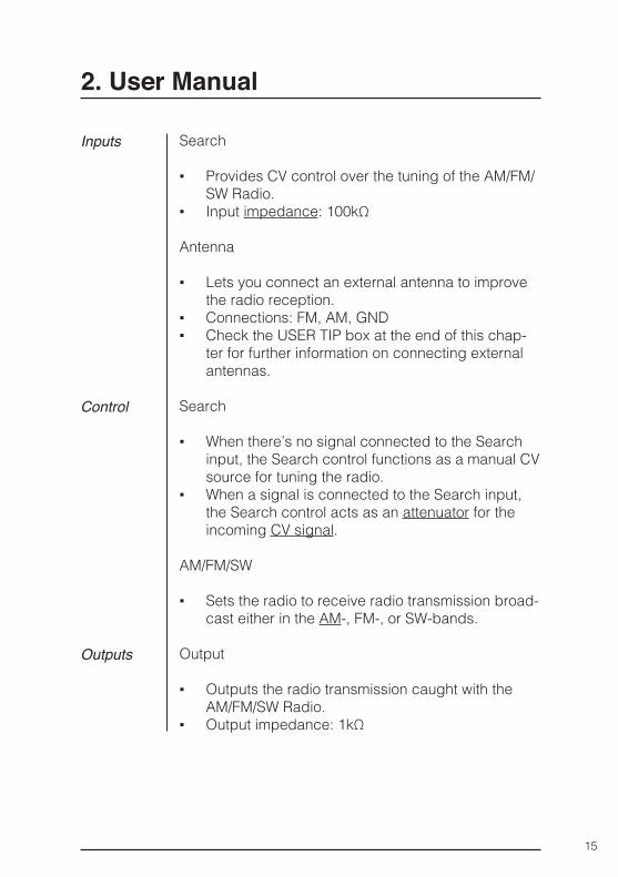
Search
▪ Provides CV control over the tuning of the AM/FM/SW Radio.
▪ Input impedance: 100kΩ
Antenna
▪ Lets you connect an external antenna to improve the radio reception.
▪ Connections: FM, AM, GND ▪ Check the USER TIP box at the end of this chap-
ter for further information on connecting external antennas.
Search
▪ When there’s no signal connected to the Search input, the Search control functions as a manual CV source for tuning the radio.
▪ When a signal is connected to the Search input, the Search control acts as an attenuator for the incoming CV signal.
AM/FM/SW
▪ Sets the radio to receive radio transmission broad-cast either in the AM-, FM-, or SW-bands.
Output
▪ Outputs the radio transmission caught with the AM/FM/SW Radio.
▪ Output impedance: 1kΩ
16
2. User Manual
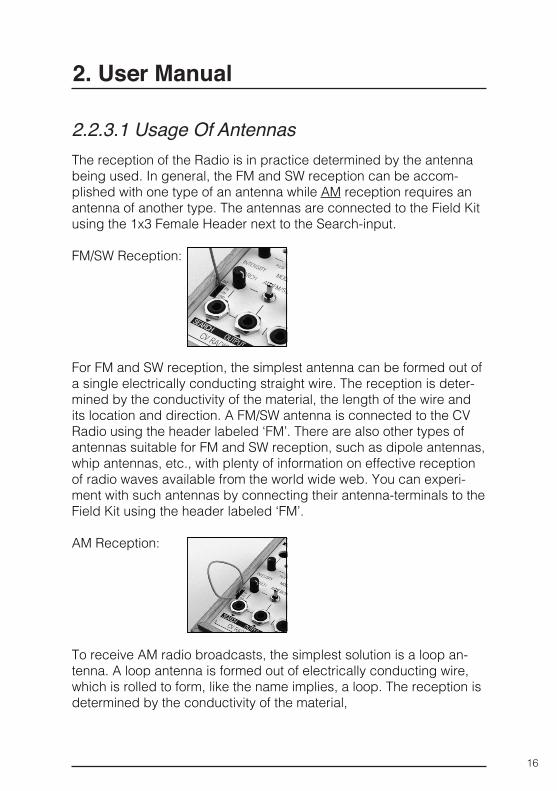
The reception of the Radio is in practice determined by the antenna being used. In general, the FM and SW reception can be accom-plished with one type of an antenna while AM reception requires an antenna of another type. The antennas are connected to the Field Kit using the 1x3 Female Header next to the Search-input.
FM/SW Reception:
For FM and SW reception, the simplest antenna can be formed out of a single electrically conducting straight wire. The reception is deter-mined by the conductivity of the material, the length of the wire and its location and direction. A FM/SW antenna is connected to the CV Radio using the header labeled ‘FM’. There are also other types of antennas suitable for FM and SW reception, such as dipole antennas, whip antennas, etc., with plenty of information on effective reception of radio waves available from the world wide web. You can experi-ment with such antennas by connecting their antenna-terminals to the Field Kit using the header labeled ‘FM’.
AM Reception:
To receive AM radio broadcasts, the simplest solution is a loop an-tenna. A loop antenna is formed out of electrically conducting wire, which is rolled to form, like the name implies, a loop. The reception is determined by the conductivity of the material,
2.2.3.1 Usage Of Antennas
17
2. User Manual
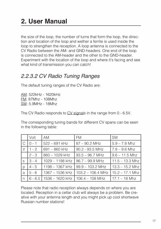
The default tuning ranges of the CV Radio are:
AM: 522kHz - 1620kHzFM: 87Mhz - 108MhzSW: 5.9MHz - 18Mhz
The CV Radio responds to CV signals in the range from 0 - 6.5V.
The corresponding tuning bands for different CV spans can be seen in the following table:
Volt AM FM SWC 0 - 1 522 – 691 kHz 87 – 90.2 MHz 5.9 – 7.8 MhzV 1 - 2 691 – 860 kHz 90.2 - 93.5 MHz 7.8 – 9.6 Mhz
2 - 3 860 – 1029 kHz 93.5 – 96.7 MHz 9.6 – 11.5 Mhzs 3 - 4 1029 – 1198 kHz 96.7 – 99.9 MHz 11.5 – 13.3 Mhzp 4 - 5 1198 – 1367 kHz 99.9 – 103.2 MHz 13.3 – 15.2 Mhza 5 - 6 1367 – 1536 kHz 103.2 – 106.4 MHz 15.2 – 17.1 Mhzn 6 - 6.5 1536 – 1620 kHz 106.4 – 108 MHz 17.1 – 18 Mhz
Please note that radio reception always depends on where you are located. Reception in a cellar club will always be a problem. Be cre-ative with your antenna length and you might pick up cool shortwave Russian number stations!
2.2.3.2 CV Radio Tuning Ranges
the size of the loop, the number of turns that form the loop, the direc-tion and location of the loop and wether a ferrite is used inside the loop to strengthen the reception. A loop antenna is connected to the CV Radio between the AM- and GND-headers. One end of the loop is connected to the AM-header and the other to the GND-header. Experiment with the location of the loop and where it’s facing and see what kind of transmission you can catch!
18
2. User Manual
2.2.4 DC Interface
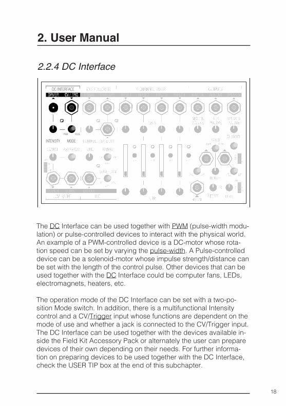
The DC Interface can be used together with PWM (pulse-width modu-lation) or pulse-controlled devices to interact with the physical world. An example of a PWM-controlled device is a DC-motor whose rota-tion speed can be set by varying the pulse-width. A Pulse-controlled device can be a solenoid-motor whose impulse strength/distance can be set with the length of the control pulse. Other devices that can be used together with the DC Interface could be computer fans, LEDs, electromagnets, heaters, etc.
The operation mode of the DC Interface can be set with a two-po-sition Mode switch. In addition, there is a multifunctional Intensity control and a CV/Trigger input whose functions are dependent on the mode of use and whether a jack is connected to the CV/Trigger input. The DC Interface can be used together with the devices available in-side the Field Kit Accessory Pack or alternately the user can prepare devices of their own depending on their needs. For further informa-tion on preparing devices to be used together with the DC Interface, check the USER TIP box at the end of this subchapter.
19
2. User Manual
PWM
In PWM-mode, the circuitry generates a steady rectangle wave signal whose pulse-width can be set from 0 to 100% either manually with the Intensity control or through the use of a CV signal. When a jack isn’t connected to the CV/Trig input, the Intensity control functions as a manual CV source which sets the pulse-width of the rectangle wave. When there is a jack connected to the CV/Trig input, the Inten-sity control functions as an attenuator for the incoming CV signal. The effect of varying the pulse-width is determined in turn by the device with which the DC Interface is used.
Pulse
In Pulse-mode, the circuitry generates a pulse of settable width whenever there’s a trigger signal present at the CV/Trig input. In this mode, the Intensity control sets the length of the output pulse. The effect of varying the pulse length is determined in turn by the device with which the DC Interface is used.
Two things to remember:
Never Ever Ever plug in a DC voltage to the Output of the DC
Interface, although we’ve implemented a reversal protection, this could damage your device and void your warranty!
You can use the DC interface with all kinds of electrical hardware, just remember to check what current it will draw. See the output sec-tion for more info. The solenoid and the DC motor that are included in the Expansion Pack will work as they should and will give you great possibilities to interact with other objects.
20
2. User Manual
Inputs
Control
Outputs
CV/Trig (multifunctional)
▪ In PWM-mode, functions as a CV input for setting the pulse-width.
▪ In Pulse-mode, functions as a Trigger input for generating pulses.
▪ Input impedance: 100kΩ
Intensity
▪ In PWM-mode, functions as a manual CV source when a jack isn’t connected to the CV/Trig input. When there’s a jack connected, the Intensity control functions as an input attenuator for the CV signal. The functional CV range is from 0 V (0% Pulse-Width) to 6.5 V (100% Pulse-Width)
▪ In Pulse-mode, sets the pulse-length of the output pulse.
▪ DC Interface Pulse mode pulse lengths: Min - 11ms (Intensity fully CCW) Max - 77ms (Intensity fully CW)
Mode
▪ Switches the operational mode between PWM- and Pulse-modes.
Driver
▪ Outputs either a PWM or a Pulse signal of the set type.
▪ Output specs: 9V DC, 500mA absolute maximum. Contains a fuse that breaks at 500mA and resets after the normal operating conditions are met.
21
2. User Manual
USER TIP: Preparing devices to be used together with the DC Interface
The DC Interface can be used together with both PWM- and pulse-controlled devices with two electronic connectors. Connection to an external device is made via a 5.5mm plug-connector. To use a device of your choice, solder the two wires coming out from the device to the 5.5mm plug so that one wire con-nects to the “tip”-terminal and the other to the “sleeve”-terminal. The polarity of the wiring depends on the device being used.
IMPORTANT! The DC Interface should only be used with external devices that can operate with 9V DC and draw no more than 500mA of current. If the exter-nal device tries to draw more than 500mA of current, the internal fuse breaks and prevents the current flow. The fuse will reset and start to conduct once the operation conditions are met again. Always carefully check the operating conditions of the device you are about to use and make sure it matches these specifications.
We know this chapter is a bit nerdy and full of terminology, so to give your eyes some rest, here is a photo of a hedgehog in a slipper...
Credit: dalangalma on FlickrCC-BY
22
2. User Manual
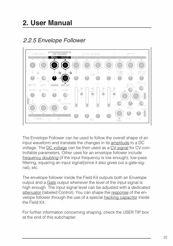
2.2.5 Envelope Follower
The Envelope Follower can be used to follow the overall shape of an input waveform and translate the changes in its amplitude to a DC voltage. The DC voltage can be then used as a CV signal for CV-con-trollable parameters. Other uses for an envelope follower include frequency doubling (if the input frequency is low enough), low-pass filtering, squaring an input signal(since it also gives out a gate-sig-nal), etc.
The envelope follower inside the Field Kit outputs both an Envelope output and a Gate output whenever the level of the input signal is high enough. The input signal level can be adjusted with a dedicated attenuator (labeled Control). You can shape the response of the en-velope follower through the use of a special hacking capacitor inside the Field Kit.
For further information concerning shaping, check the USER TIP box at the end of this subchapter.
23
2. User Manual
Inputs
Control
Outputs
Signal
▪ AC-coupled inputs for audio/CV-signals. ▪ Input Impedance: 100kΩ
Control
▪ Input attenuator for the signal present at the Signal in.
Envelope
▪ Outputs an envelope of the input signal. For information on how to tweak the response of the Envelope Follower, check the USER TIP box at the end of this chapter.
▪ Output Impedance: 1kΩ
Gate Out
▪ Gives out a gate signal whenever the input signal level is higher than ~1V.
▪ Gate out level: 7.5 V ▪ Output Impedance: 1kΩ
24
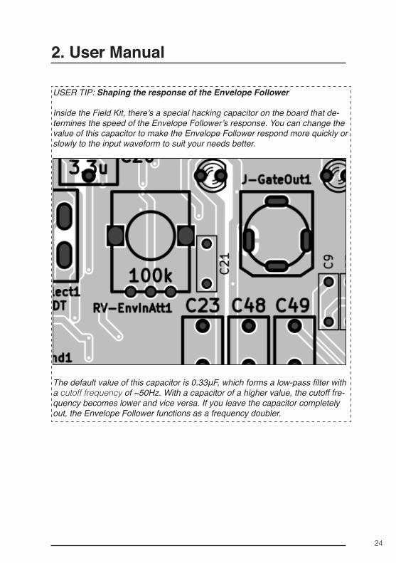
USER TIP: Shaping the response of the Envelope Follower
Inside the Field Kit, there’s a special hacking capacitor on the board that de-termines the speed of the Envelope Follower’s response. You can change the value of this capacitor to make the Envelope Follower respond more quickly or slowly to the input waveform to suit your needs better.
The default value of this capacitor is 0.33μF, which forms a low-pass filter with a cutoff frequency of ~50Hz. With a capacitor of a higher value, the cutoff fre-quency becomes lower and vice versa. If you leave the capacitor completely out, the Envelope Follower functions as a frequency doubler.
2. User Manual
25
2. User Manual
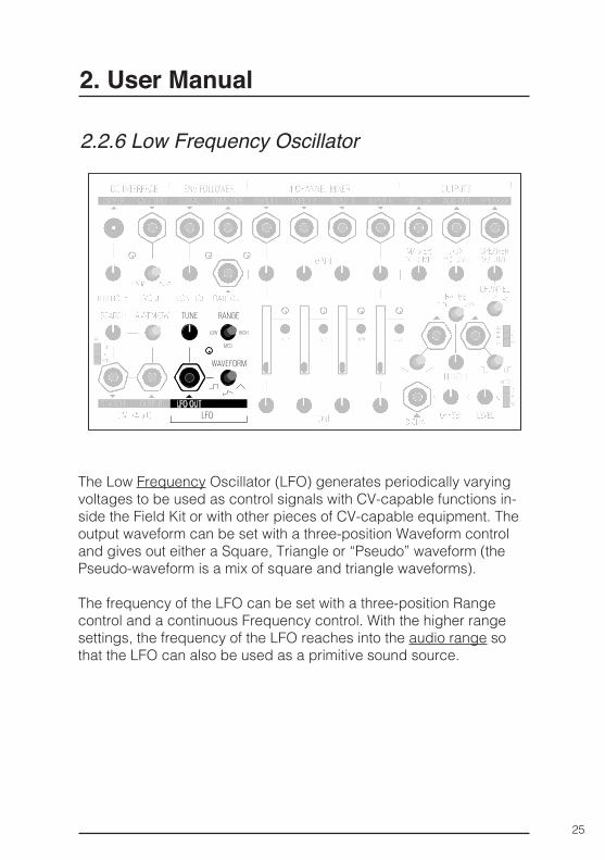
2.2.6 Low Frequency Oscillator
The Low Frequency Oscillator (LFO) generates periodically varying voltages to be used as control signals with CV-capable functions in-side the Field Kit or with other pieces of CV-capable equipment. The output waveform can be set with a three-position Waveform control and gives out either a Square, Triangle or “Pseudo” waveform (the Pseudo-waveform is a mix of square and triangle waveforms).
The frequency of the LFO can be set with a three-position Range control and a continuous Frequency control. With the higher range settings, the frequency of the LFO reaches into the audio range so that the LFO can also be used as a primitive sound source.
26
2. User Manual
Inputs
Control
Outputs
None
Range
▪ Selects one of the three frequency ranges. By default the standard ranges are:
= ~ 1/30 Hz – ~ 3Hz (LOW) = ~ 1/3 Hz – ~ 40Hz (MED) = ~ 4Hz – ~ 400Hz (HIGH) ▪ You can tune the frequency ranges to better suit
your needs by changing the internal hacking ca-pacitors inside the Field Kit. For further information on how to tune the frequencies, check the end of this chapter.
Tune
▪ Continuously sets the oscillation frequency inside the set frequency Range.
Waveform
▪ Sets the output waveform. Can be set to either Square, Pseudo (mixture between square and triangle) and Triangle waveforms.
LFO Out
▪ Gives out a periodically varying voltage of a spec-ified shape.
▪ Output Impedance: 1kΩ ▪ Output range: 0 – 6.5 Volts.
27
2. User Manual
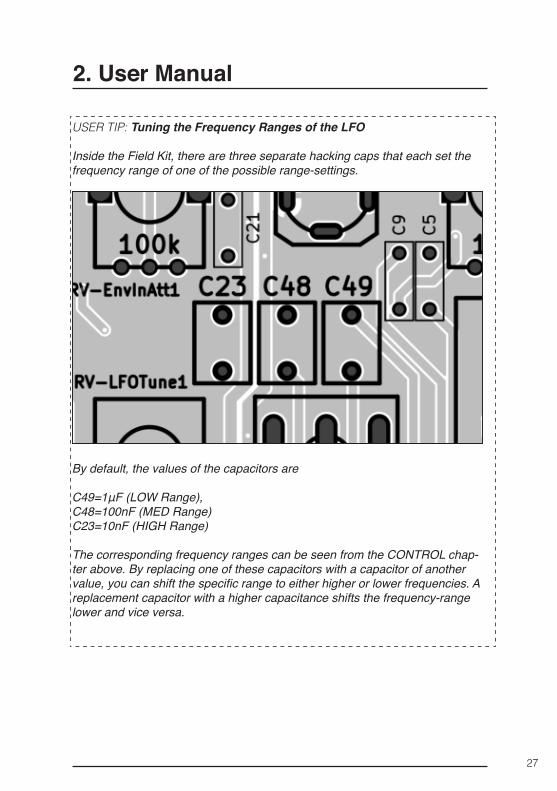
USER TIP: Tuning the Frequency Ranges of the LFO
Inside the Field Kit, there are three separate hacking caps that each set the frequency range of one of the possible range-settings.
By default, the values of the capacitors are
C49=1μF (LOW Range), C48=100nF (MED Range)C23=10nF (HIGH Range)
The corresponding frequency ranges can be seen from the CONTROL chap-ter above. By replacing one of these capacitors with a capacitor of another value, you can shift the specific range to either higher or lower frequencies. A replacement capacitor with a higher capacitance shifts the frequency-range lower and vice versa.
28
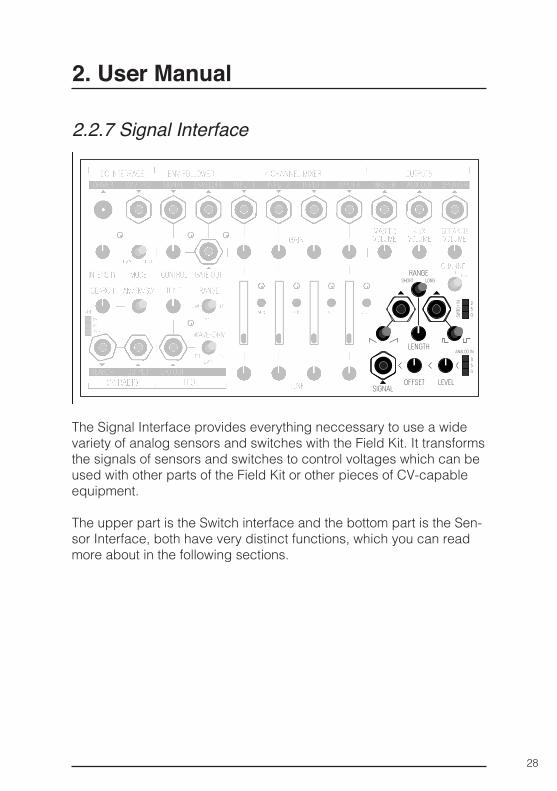
2.2.7 Signal Interface
The Signal Interface provides everything neccessary to use a wide variety of analog sensors and switches with the Field Kit. It transforms the signals of sensors and switches to control voltages which can be used with other parts of the Field Kit or other pieces of CV-capable equipment.
The upper part is the Switch interface and the bottom part is the Sen-sor Interface, both have very distinct functions, which you can read more about in the following sections.
2. User Manual
29
Inputs
Control
Switch In
▪ Connect a switch to the pins marked “SWITCH IN“ ▪ D – Data input, 5 – 5V output, G – Ground
Length
▪ Adjust the length of the trigger that is present at the outputs when the switch at the input is con-nected to 5V. This setting applies to both signal outputs: gate and ramp.
Range
▪ Short: minimum 1ms, maximum 33ms ▪ Long: minimum 33ms, maximum 1s
Gate/Inverted Gate Switch
▪ Choose which type of gate signal should be pres-ent at the corresponding output.
▪ Voltage Range: 0 – 7.8 V
Ramp/Sawtooth Switch
▪ Choose which type of gate signal should be pres-ent at the corresponding output.
▪ Voltage Range: 0 – 7.8 V
2. User Manual
2.2.7.1 Switch InterfaceThe Switch Interface transforms signals from different switches like buttons, ball- or tilt-switches etc. into four different types of signals on two outputs. It can output gates, inverted gates, ramp or sawtooth signals of adjustable length. The two outputs can be used at the same time.
30
2.2.7.2 Sensor InterfaceThe Sensor Interface is capable of manipulating the output of analog sensors like light-sensitive resistors or heat sensors to be used with the CV-controllable functions of the Field Kit or other CV-capable gear.
Output Gate/Inverted gate
▪ Sends out an gate or inverted gate of adjust-able length when a positive signal is present on the switch in, depending on the settings of the length-controls.
Ramp/Sawtooth
▪ Sends out an ramp or sawtooth of adjustable length when a positive signal is present on the switch in, depending on the settings of the length-controls.
Output specifications
▪ Voltage Range: 0 – 7.8 V
2. User Manual
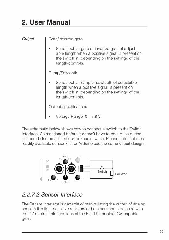
ResistorSwitch
The schematic below shows how to connect a switch to the Switch Interface. As mentioned before it doesn’t have to be a push button but could also be a tilt, shock or knock switch. Please note that most readily available sensor kits for Arduino use the same circuit design!
31
Inputs
Control
Outputs
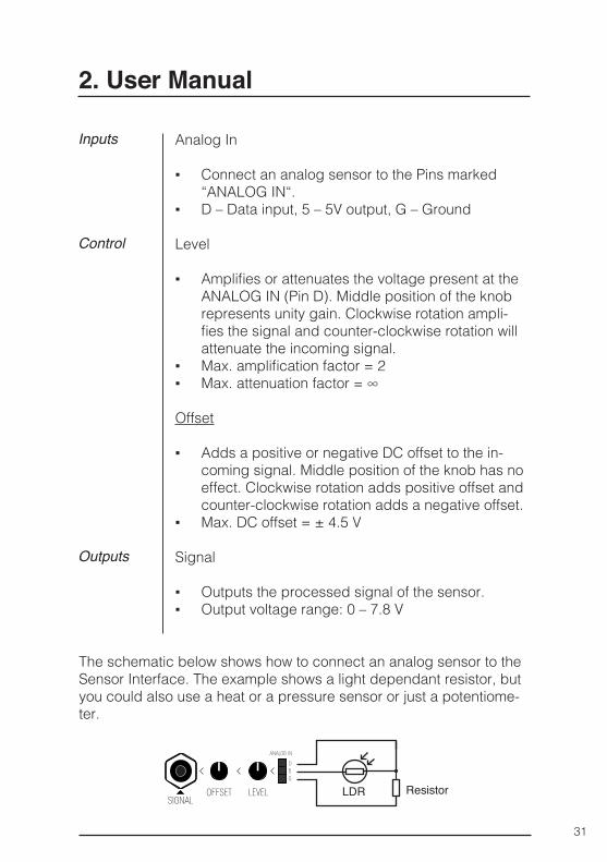
Analog In
▪ Connect an analog sensor to the Pins marked “ANALOG IN“.
▪ D – Data input, 5 – 5V output, G – Ground
Level
▪ Amplifies or attenuates the voltage present at the ANALOG IN (Pin D). Middle position of the knob represents unity gain. Clockwise rotation ampli-fies the signal and counter-clockwise rotation will attenuate the incoming signal.
▪ Max. amplification factor = 2 ▪ Max. attenuation factor = ∞
Offset
▪ Adds a positive or negative DC offset to the in-coming signal. Middle position of the knob has no effect. Clockwise rotation adds positive offset and counter-clockwise rotation adds a negative offset.
▪ Max. DC offset = ± 4.5 V
Signal
▪ Outputs the processed signal of the sensor. ▪ Output voltage range: 0 – 7.8 V
2. User Manual
ResistorLDR
The schematic below shows how to connect an analog sensor to the Sensor Interface. The example shows a light dependant resistor, but you could also use a heat or a pressure sensor or just a potentiome-ter.
32
2. User Manual
2.2.8 Field Kit In A Eurorack System
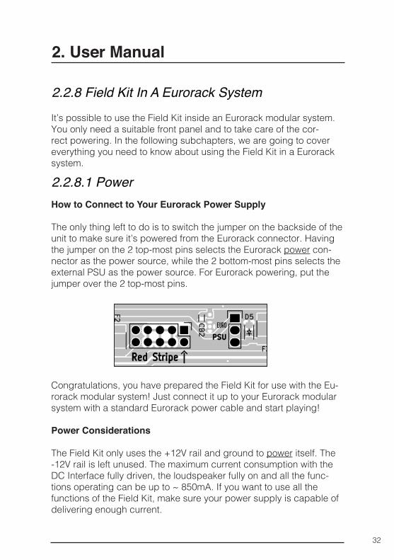
2.2.8.1 PowerHow to Connect to Your Eurorack Power Supply
The only thing left to do is to switch the jumper on the backside of the unit to make sure it’s powered from the Eurorack connector. Having the jumper on the 2 top-most pins selects the Eurorack power con-nector as the power source, while the 2 bottom-most pins selects the external PSU as the power source. For Eurorack powering, put the jumper over the 2 top-most pins.
Congratulations, you have prepared the Field Kit for use with the Eu-rorack modular system! Just connect it up to your Eurorack modular system with a standard Eurorack power cable and start playing!
Power Considerations
The Field Kit only uses the +12V rail and ground to power itself. The -12V rail is left unused. The maximum current consumption with the DC Interface fully driven, the loudspeaker fully on and all the func-tions operating can be up to ~ 850mA. If you want to use all the functions of the Field Kit, make sure your power supply is capable of delivering enough current.
It’s possible to use the Field Kit inside an Eurorack modular system. You only need a suitable front panel and to take care of the cor-rect powering. In the following subchapters, we are going to cover everything you need to know about using the Field Kit in a Eurorack system.
33
2. User Manual
To use the Field Kit inside a Eurorack modular system, you’ll need a suitable Eurorack panel for it. You can get the official KOMA Elektron-ik front panel (sold separately) or fabricate/DIY your own using the design files provided on the KOMA Elektronik website.
To prepare the Field Kit for use inside the Eurorack system, you need to first take it out from its standard enclosure. To do this, first untight-en all the the nuts from the minijack connectors. Next, carefully lift the front panel from its place to reveal the circuit board. Next, unscrew the four mounting screws on the corners of the circuit board to de-tach it from the enclosure. You can now lift the circuit board out of the enclosure.
Next, carefully fit the Eurorack front panel over the unit, making sure all the mechanical parts are in their place. Pay extra attention to the LEDs, they might easily bend and twist to the side. If that happens, just carefully bend them back to their original place. When you have the front panel in place, tighten all the nuts on the minijack connec-tors.
2.2.8.2 Panel
34
3. 50 Ways To Use The Field Kit
3.1 In the Kitchen
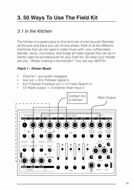
The kitchen is a great place to find all kinds of cool sounds! Besides all the pots and pans you can hit and shake, think of all the different machines that can be used to make music with: your coffeemaker, blender, stove, microwave, and fridge all make signals that can be in-stantly used as soundsources for your Field Kit. So when your friends ask you, “Whats cooking in the kitchen?” You can say: BEATS!
Patch 1 - Dinner Music
▪ Channel 1 aux button engaged. ▪ Aux out -> Env Follower signal in. ▪ Env Follower Envelope out -> CV radio Search in. ▪ CV Radio output -> 4 channel mixer input 2.
Contact mic to kitchen Main Output
35
3. 50 Ways To Use The Field Kit
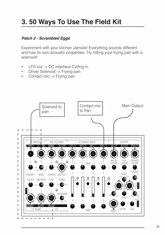
Patch 2 - Scrambled Eggs
Experiment with your kitchen utensils! Everything sounds different and has its own acoustic properties. Try hitting your frying pan with a solenoid!
▪ LFO out -> DC interface CV/trig in ▪ Driver Solenoid -> Frying pan ▪ Contact mic -> Frying pan
Main OutputSolenoid to pan
Contact mic to Pan
36
3. 50 Ways To Use The Field Kit
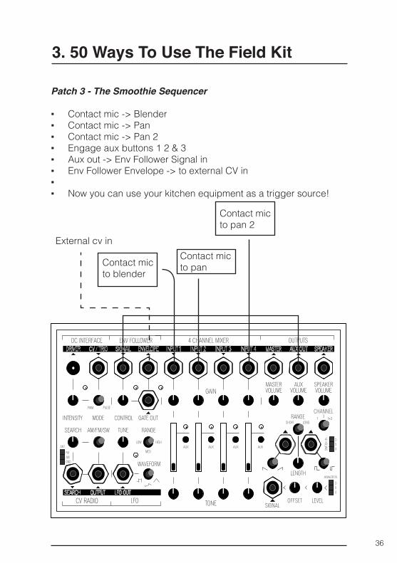
Patch 3 - The Smoothie Sequencer
▪ Contact mic -> Blender ▪ Contact mic -> Pan ▪ Contact mic -> Pan 2 ▪ Engage aux buttons 1 2 & 3 ▪ Aux out -> Env Follower Signal in ▪ Env Follower Envelope -> to external CV in ▪ ▪ Now you can use your kitchen equipment as a trigger source!
Contact mic to blender
Contact mic to pan
Contact mic to pan 2
External cv in
37
3. 50 Ways To Use The Field Kit
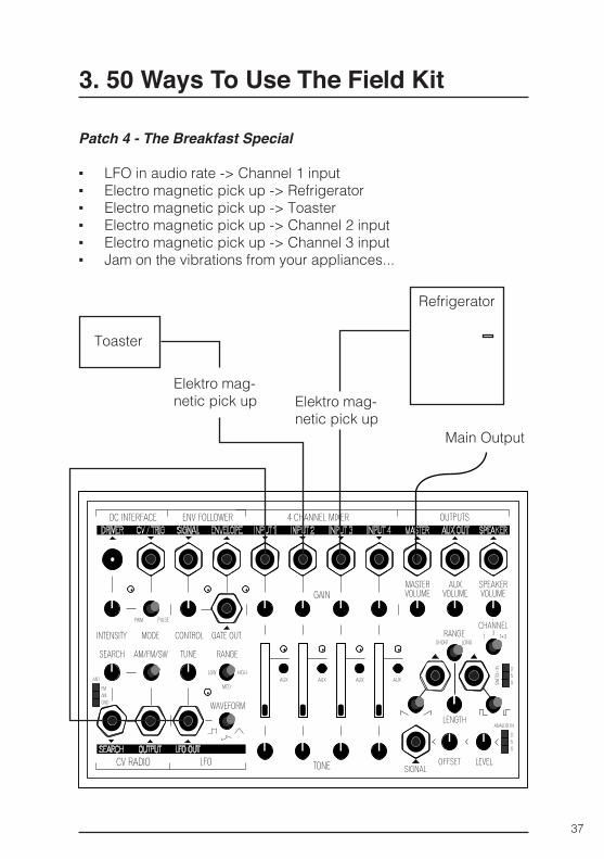
Patch 4 - The Breakfast Special
▪ LFO in audio rate -> Channel 1 input ▪ Electro magnetic pick up -> Refrigerator ▪ Electro magnetic pick up -> Toaster ▪ Electro magnetic pick up -> Channel 2 input ▪ Electro magnetic pick up -> Channel 3 input ▪ Jam on the vibrations from your appliances...
Main Output
Elektro mag-netic pick up
Refrigerator
Elektro mag-netic pick up
Toaster
38
3. 50 Ways To Use The Field Kit
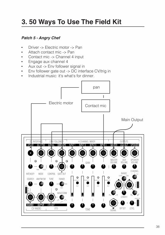
Patch 5 - Angry Chef
▪ Driver -> Electric motor -> Pan ▪ Attach contact mic -> Pan ▪ Contact mic -> Channel 4 input ▪ Engage aux channel 4 ▪ Aux out -> Env follower signal in ▪ Env follower gate out -> DC interface CV/trig in ▪ Industrial music: it’s what’s for dinner.
Main Output
Electric motor
pan
Contact mic
39
3. 50 Ways To Use The Field Kit
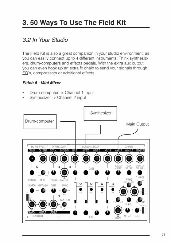
3.2 In Your Studio
The Field Kit is also a great companion in your studio environment, as you can easily connect up to 4 different instruments. Think synthesiz-ers, drum-computers and effects pedals. With the extra aux output, you can even hook up an extra fx chain to send your signals through EQ’s, compressors or additional effects.
Patch 6 - Mini Mixer
▪ Drum-computer -> Channel 1 input ▪ Synthesizer -> Channel 2 input
Drum-computer
Synthesizer
Main Output
40
3. 50 Ways To Use The Field Kit
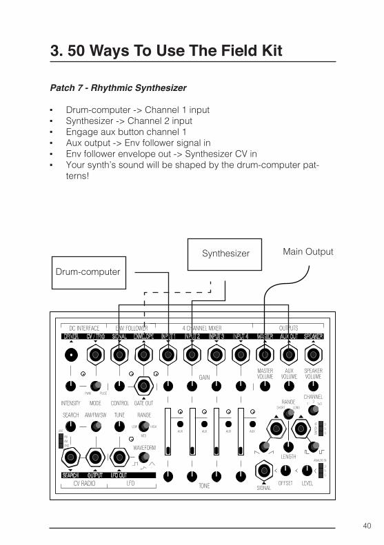
Patch 7 - Rhythmic Synthesizer
▪ Drum-computer -> Channel 1 input ▪ Synthesizer -> Channel 2 input ▪ Engage aux button channel 1 ▪ Aux output -> Env follower signal in ▪ Env follower envelope out -> Synthesizer CV in ▪ Your synth’s sound will be shaped by the drum-computer pat-
terns!
Drum-computer
Synthesizer Main Output
41
3. 50 Ways To Use The Field Kit
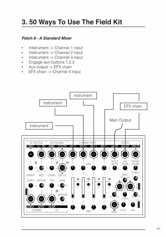
Patch 8 - A Standard Mixer
▪ Intstrument -> Channel 1 input ▪ Intstrument -> Channel 2 input ▪ Intstrument -> Channel 3 input ▪ Engage aux buttons 1,2,3 ▪ Aux output -> EFX chain ▪ EFX chain -> Channel 4 input
Main Outputinstrument
instrument
instrument
EFX chain
42
3. 50 Ways To Use The Field Kit
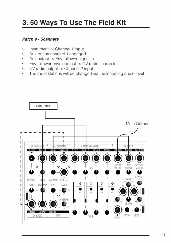
Patch 9 - Scanners
▪ Instrument -> Channel 1 input ▪ Aux button channel 1 engaged ▪ Aux output -> Env follower signal in ▪ Env follower envelope out -> CV radio search in ▪ CV radio output -> Channel 2 input ▪ The radio stations will be changed via the incoming audio level
Main Output
instrument
43
3. 50 Ways To Use The Field Kit
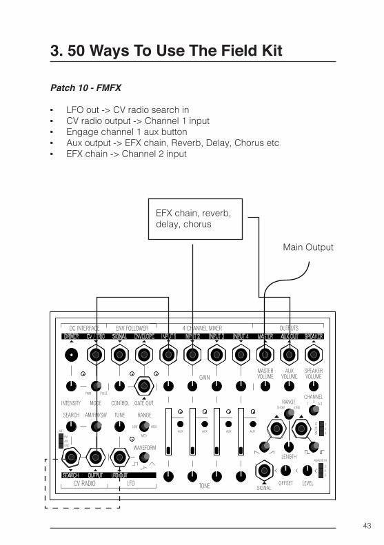
Patch 10 - FMFX
▪ LFO out -> CV radio search in ▪ CV radio output -> Channel 1 input ▪ Engage channel 1 aux button ▪ Aux output -> EFX chain, Reverb, Delay, Chorus etc ▪ EFX chain -> Channel 2 input
Main Output
EFX chain, reverb, delay, chorus
44
3. 50 Ways To Use The Field Kit
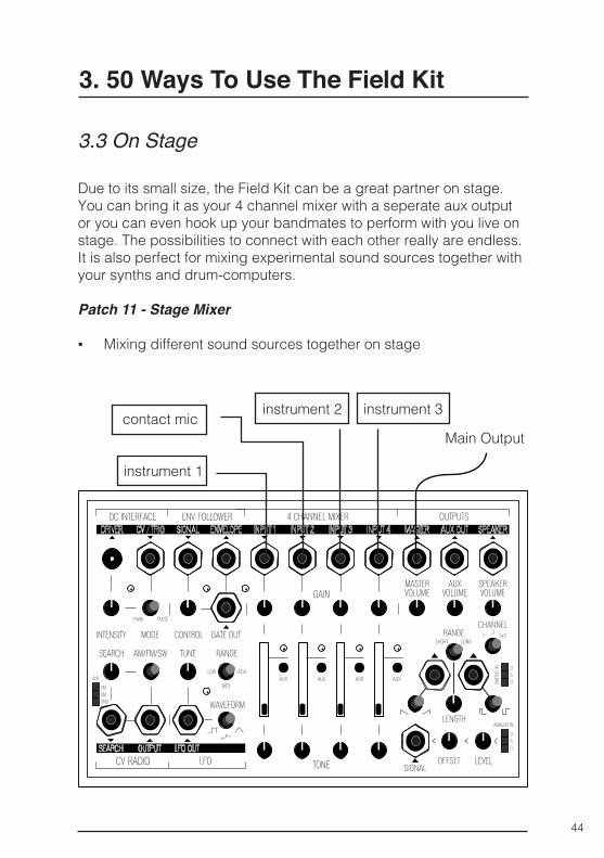
3.3 On Stage
Due to its small size, the Field Kit can be a great partner on stage. You can bring it as your 4 channel mixer with a seperate aux output or you can even hook up your bandmates to perform with you live on stage. The possibilities to connect with each other really are endless. It is also perfect for mixing experimental sound sources together with your synths and drum-computers.
Patch 11 - Stage Mixer
▪ Mixing different sound sources together on stage
Main Outputcontact mic
instrument 1
instrument 2 instrument 3
45
3. 50 Ways To Use The Field Kit
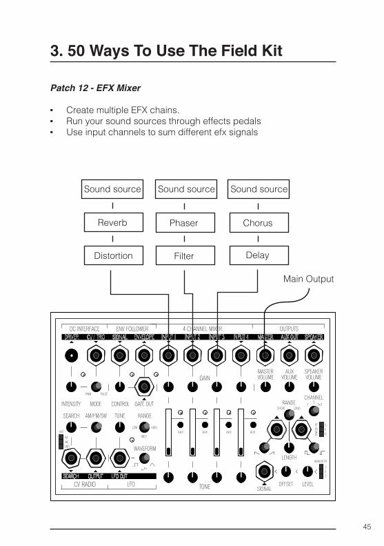
Patch 12 - EFX Mixer
▪ Create multiple EFX chains. ▪ Run your sound sources through effects pedals ▪ Use input channels to sum different efx signals
Main Output
Sound source Sound source Sound source
Reverb
Distortion
Phaser Chorus
Filter Delay
46
3. 50 Ways To Use The Field Kit
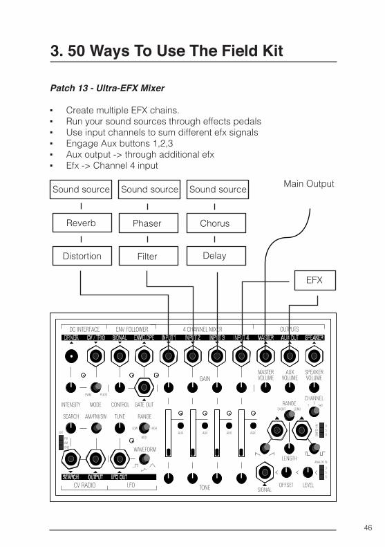
Patch 13 - Ultra-EFX Mixer
▪ Create multiple EFX chains. ▪ Run your sound sources through effects pedals ▪ Use input channels to sum different efx signals ▪ Engage Aux buttons 1,2,3 ▪ Aux output -> through additional efx ▪ Efx -> Channel 4 input
Main OutputSound source Sound source Sound source
Reverb
Distortion
Phaser Chorus
Filter Delay
EFX
47
3. 50 Ways To Use The Field Kit
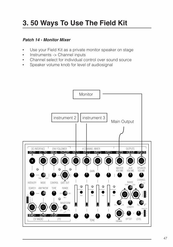
Patch 14 - Monitor Mixer
▪ Use your Field Kit as a private monitor speaker on stage ▪ Instruments -> Channel inputs ▪ Channel select for individual control over sound source ▪ Speaker volume knob for level of audiosignal
Main Outputinstrument 2 instrument 3
Monitor
48
3. 50 Ways To Use The Field Kit
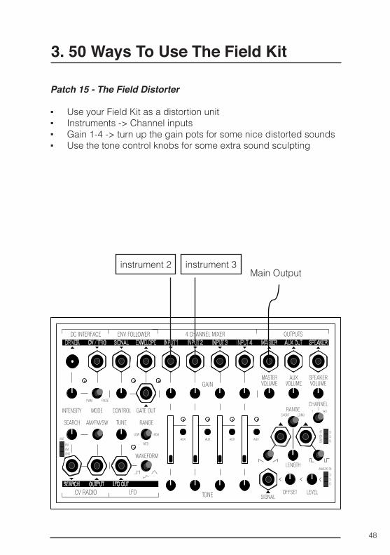
Patch 15 - The Field Distorter
▪ Use your Field Kit as a distortion unit ▪ Instruments -> Channel inputs ▪ Gain 1-4 -> turn up the gain pots for some nice distorted sounds ▪ Use the tone control knobs for some extra sound sculpting
Main Outputinstrument 2 instrument 3
49
3. 50 Ways To Use The Field Kit
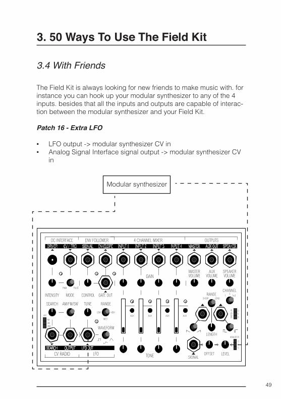
3.4 With Friends
The Field Kit is always looking for new friends to make music with. for instance you can hook up your modular synthesizer to any of the 4 inputs. besides that all the inputs and outputs are capable of interac-tion between the modular synthesizer and your Field Kit.
Patch 16 - Extra LFO
▪ LFO output -> modular synthesizer CV in ▪ Analog Signal Interface signal output -> modular synthesizer CV
in
Modular synthesizer
50
3. 50 Way’s To Use The Field Kit
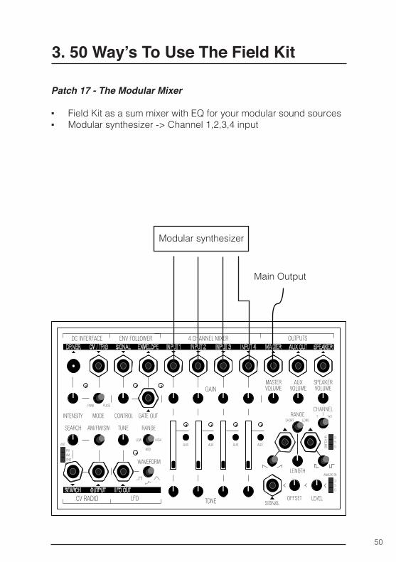
Patch 17 - The Modular Mixer
▪ Field Kit as a sum mixer with EQ for your modular sound sources ▪ Modular synthesizer -> Channel 1,2,3,4 input
Main Output
Modular synthesizer
51
3. 50 Way’s To Use The Field Kit
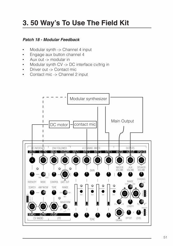
Patch 18 - Modular Feedback
▪ Modular synth -> Channel 4 input ▪ Engage aux button channel 4 ▪ Aux out -> modular in ▪ Modular synth CV -> DC interface cv/trig in ▪ Driver out -> Contact mic ▪ Contact mic -> Channel 2 input
Main Output
Modular synthesizer
DC motor contact mic
52
3. 50 Way’s To Use The Field Kit
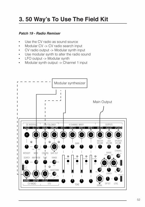
Patch 19 - Radio Remixer
▪ Use the CV radio as sound source ▪ Modular CV -> CV radio search input ▪ CV radio output -> Modular synth input ▪ Use modular synth to alter the radio sound ▪ LFO output -> Modular synth ▪ Modular synth output -> Channel 1 input
Main Output
Modular synthesizer
53
3. 50 Way’s To Use The Field Kit
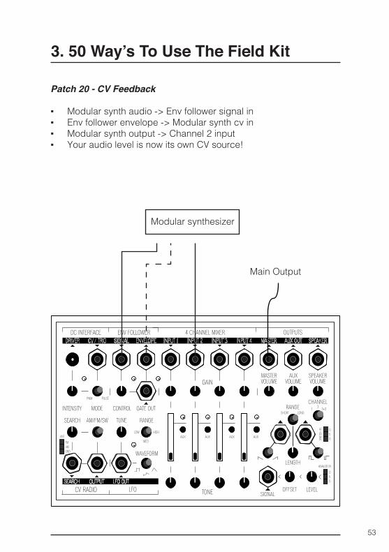
Patch 20 - CV Feedback
▪ Modular synth audio -> Env follower signal in ▪ Env follower envelope -> Modular synth cv in ▪ Modular synth output -> Channel 2 input ▪ Your audio level is now its own CV source!
Main Output
Modular synthesizer
54
3. 50 Way’s To Use The Field Kit
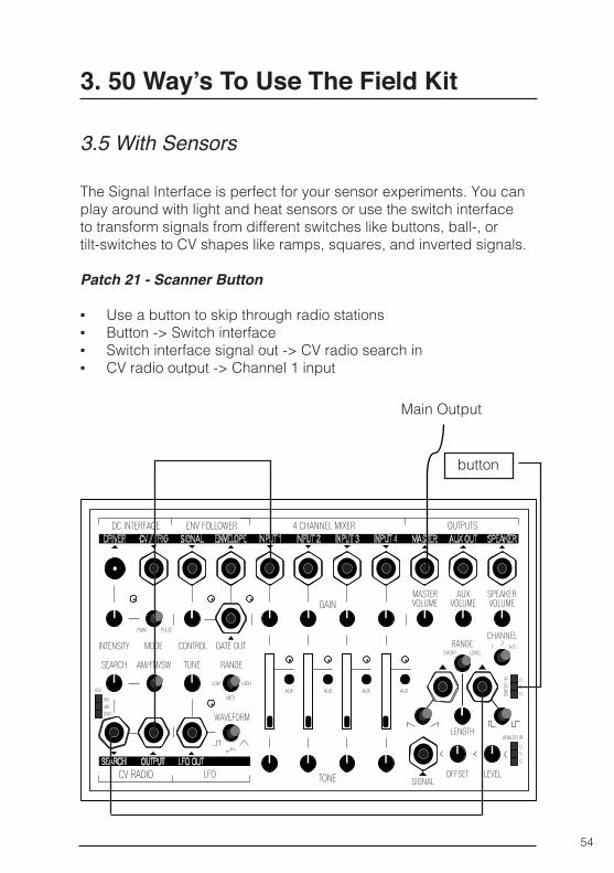
3.5 With Sensors
The Signal Interface is perfect for your sensor experiments. You can play around with light and heat sensors or use the switch interface to transform signals from different switches like buttons, ball-, or tilt-switches to CV shapes like ramps, squares, and inverted signals.
Patch 21 - Scanner Button
▪ Use a button to skip through radio stations ▪ Button -> Switch interface ▪ Switch interface signal out -> CV radio search in ▪ CV radio output -> Channel 1 input
button
Main Output
55
3. 50 Way’s To Use The Field Kit
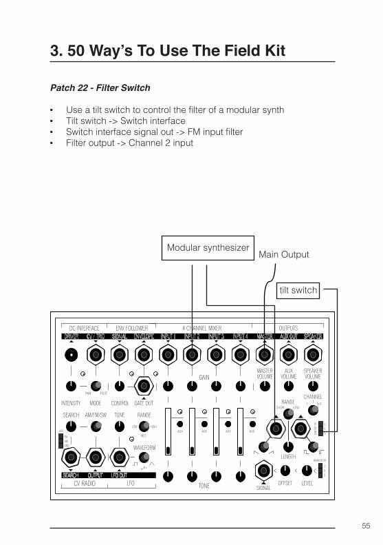
Patch 22 - Filter Switch
▪ Use a tilt switch to control the filter of a modular synth ▪ Tilt switch -> Switch interface ▪ Switch interface signal out -> FM input filter ▪ Filter output -> Channel 2 input
tilt switch
Modular synthesizerMain Output
56
3. 50 Way’s To Use The Field Kit
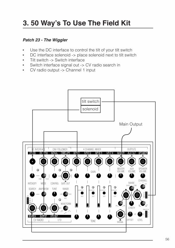
Patch 23 - The Wiggler
▪ Use the DC interface to control the tilt of your tilt switch ▪ DC interface solenoid -> place solenoid next to tilt switch ▪ Tilt switch -> Switch interface ▪ Switch interface signal out -> CV radio search in ▪ CV radio output -> Channel 1 input
tilt switchsolenoid
Main Output

57
3. 50 Way’s To Use The Field Kit
Patch 24 - The Hot Tamale
▪ Use a heat sensor to control a solenoid’s push ▪ Heat sensor -> Analog Sensor In ▪ Analog sensor signal out -> Envelope Follower Signal In ▪ Envelope Follower Gate Out -> DC interface CV/trig in ▪ DC interface driver out -> Solenoid
heat sensor
heating
Solenoid
58
3. 50 Way’s To Use The Field Kit
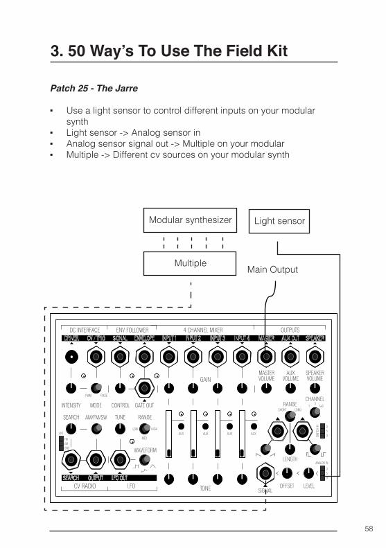
Patch 25 - The Jarre
▪ Use a light sensor to control different inputs on your modular synth
▪ Light sensor -> Analog sensor in ▪ Analog sensor signal out -> Multiple on your modular ▪ Multiple -> Different cv sources on your modular synth
Main Output
Modular synthesizer Light sensor
Multiple
59
3. 50 Way’s To Use The Field Kit
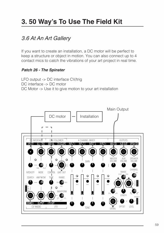
3.6 At An Art Gallery
If you want to create an installation, a DC motor will be perfect to keep a structure or object in motion. You can also connect up to 4 contact mics to catch the vibrations of your art project in real time.
Patch 26 - The Spinster
LFO output -> DC interface CV/trigDC interface -> DC motor DC Motor -> Use it to give motion to your art installation
Main OutputDC motor Installation
60
3. 50 Way’s To Use The Field Kit
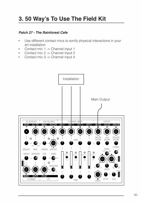
Patch 27 - The Rainforest Cafe
▪ Use different contact mics to sonify physical interactions in your art installation
▪ Contact mic 1 -> Channel input 1 ▪ Contact mic 2 -> Channel input 2 ▪ Contact mic 3 -> Channel input 4
Main Output
Installation
61
3. 50 Way’s To Use The Field Kit
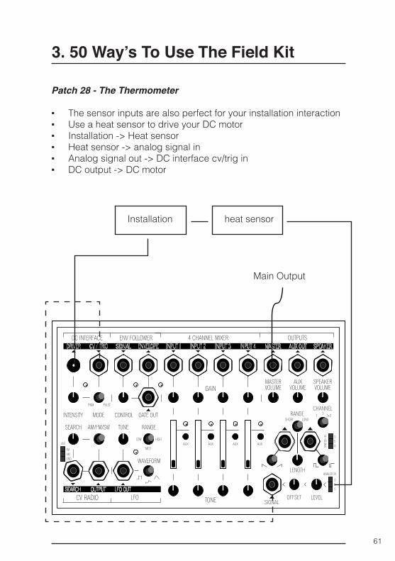
Patch 28 - The Thermometer
▪ The sensor inputs are also perfect for your installation interaction ▪ Use a heat sensor to drive your DC motor ▪ Installation -> Heat sensor ▪ Heat sensor -> analog signal in ▪ Analog signal out -> DC interface cv/trig in ▪ DC output -> DC motor
Main Output
Installation heat sensor
62
3. 50 Way’s To Use The Field Kit
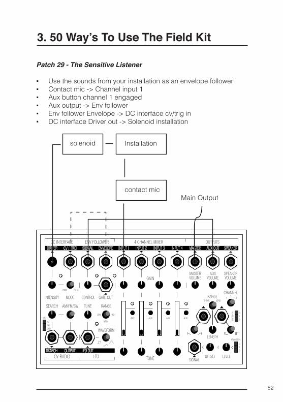
Patch 29 - The Sensitive Listener
▪ Use the sounds from your installation as an envelope follower ▪ Contact mic -> Channel input 1 ▪ Aux button channel 1 engaged ▪ Aux output -> Env follower ▪ Env follower Envelope -> DC interface cv/trig in ▪ DC interface Driver out -> Solenoid installation
Main Output
Installation
contact mic
solenoid
63
3. 50 Way’s To Use The Field Kit
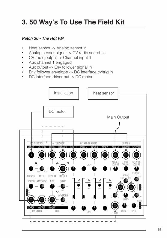
Patch 30 - The Hot FM
▪ Heat sensor -> Analog sensor in ▪ Analog sensor signal -> CV radio search in ▪ CV radio output -> Channel input 1 ▪ Aux channel 1 engaged ▪ Aux output -> Env follower signal in ▪ Env follower envelope -> DC interface cv/trig in ▪ DC interface driver out -> DC motor
Main Output
Installation
DC motor
heat sensor
64
3. 50 Way’s To Use The Field Kit
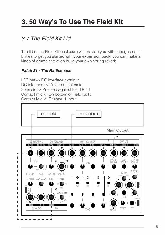
3.7 The Field Kit Lid
The lid of the Field Kit enclosure will provide you with enough possi-bilities to get you started with your expansion pack. you can make all kinds of drums and even build your own spring reverb.
Patch 31 - The Rattlesnake
LFO out -> DC interface cv/trig inDC interface -> Driver out solenoid Solenoid -> Pressed against Field Kit litContact mic -> On bottom of Field Kit litContact Mic -> Channel 1 input
Main Output
solenoid contact mic
65
3. 50 Way’s To Use The Field Kit
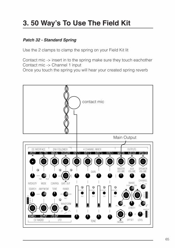
Patch 32 - Standard Spring
Use the 2 clamps to clamp the spring on your Field Kit lit
Contact mic -> insert in to the spring make sure they touch eachotherContact mic -> Channel 1 inputOnce you touch the spring you will hear your created spring reverb
Main Output
contact mic
66
3. 50 Way’s To Use The Field Kit
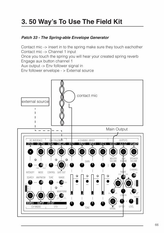
Patch 33 - The Spring-able Envelope Generator
Contact mic -> insert in to the spring make sure they touch eachotherContact mic -> Channel 1 inputOnce you touch the spring you will hear your created spring reverbEngage aux button channel 1Aux output -> Env follower signal inEnv follower envelope - > External source
Main Output
contact micexternal source
67
3. 50 Way’s To Use The Field Kit
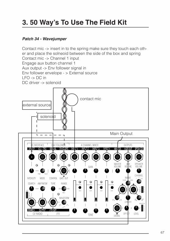
Patch 34 - Wavejumper
Contact mic -> insert in to the spring make sure they touch each oth-er and place the solneoid between the side of the box and springContact mic -> Channel 1 inputEngage aux button channel 1Aux output -> Env follower signal inEnv follower envelope - > External sourceLFO -> DC inDC driver -> solenoid
Main Output
contact micexternal source
solenoid
68
3. 50 Way’s To Use The Field Kit
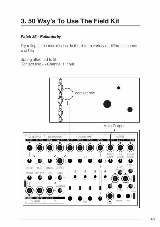
Patch 35 - Rollerderby
Try roling some marbles inside the lit for a variety of different sounds and hits
Spring attached to litContact mic -> Channel 1 input
Main Output
contact mic
69
3. 50 Way’s To Use The Field Kit
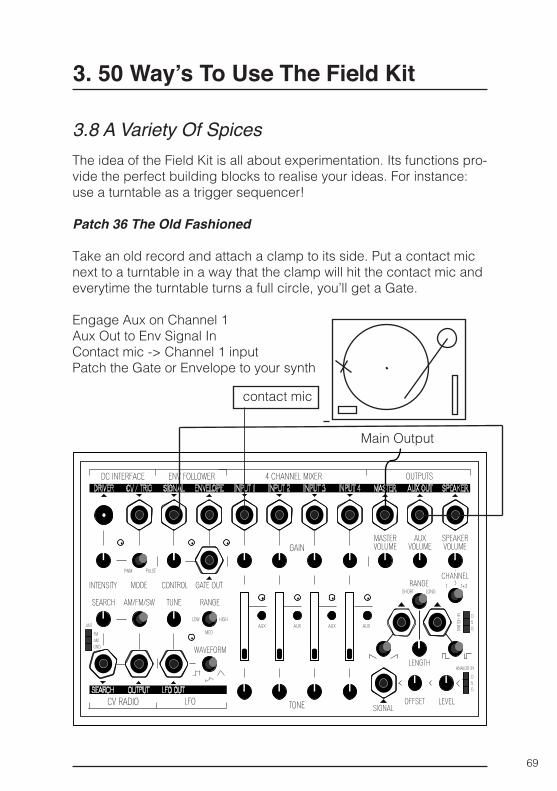
3.8 A Variety Of SpicesThe idea of the Field Kit is all about experimentation. Its functions pro-vide the perfect building blocks to realise your ideas. For instance: use a turntable as a trigger sequencer!
Patch 36 The Old Fashioned
Take an old record and attach a clamp to its side. Put a contact mic next to a turntable in a way that the clamp will hit the contact mic and everytime the turntable turns a full circle, you’ll get a Gate.
Engage Aux on Channel 1Aux Out to Env Signal InContact mic -> Channel 1 inputPatch the Gate or Envelope to your synth
Main Output
contact mic
70
3. 50 Way’s To Use The Field Kit
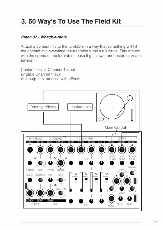
Patch 37 - Whack-a-mole
Attach a contact mic to the turntable in a way that something will hit the contact mic everytime the turntable turns a full circle. Play around with the speed of the turntable, make it go slower and faster to create tension.
Contact mic -> Channel 1 inputEngage Channel 1 auxAux output -> process with effects.
Main Output
contact micExternal effects
71
3. 50 Way’s To Use The Field Kit
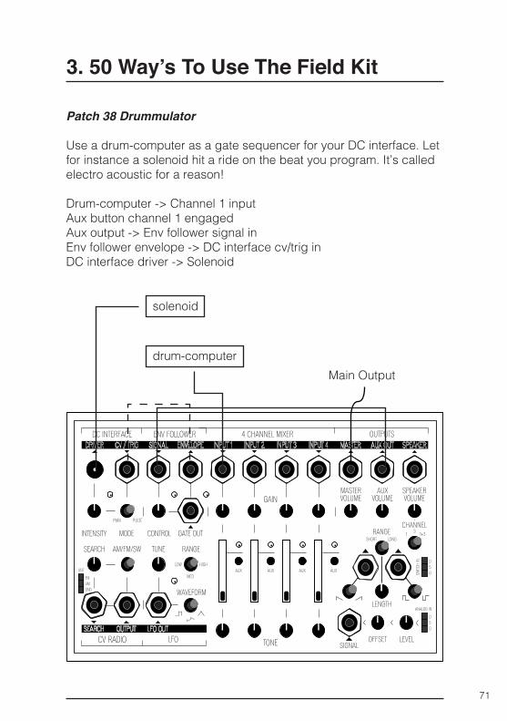
Patch 38 Drummulator
Use a drum-computer as a gate sequencer for your DC interface. Let for instance a solenoid hit a ride on the beat you program. It’s called electro acoustic for a reason!
Drum-computer -> Channel 1 inputAux button channel 1 engagedAux output -> Env follower signal inEnv follower envelope -> DC interface cv/trig inDC interface driver -> Solenoid
Main Outputdrum-computer
solenoid
72
3. 50 Way’s To Use The Field Kit
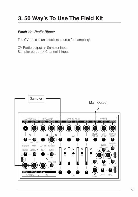
Patch 39 - Radio Ripper
The CV radio is an excellent source for sampling!
CV Radio output -> Sampler inputSampler output -> Channel 1 input
Main OutputSampler
73
3. 50 Way’s To Use The Field Kit
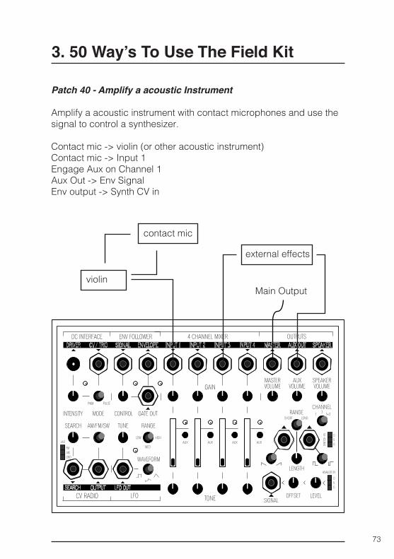
Patch 40 - Amplify a acoustic Instrument
Amplify a acoustic instrument with contact microphones and use the signal to control a synthesizer.
Contact mic -> violin (or other acoustic instrument)Contact mic -> Input 1Engage Aux on Channel 1Aux Out -> Env SignalEnv output -> Synth CV in
Main Outputviolin
contact mic
external effects
74
3. 50 Way’s To Use The Field Kit
3.9 KOMA FavouritesThe following patches are some of our Field Kit favourites, we hope you enjoyed all our patches and that it will give you some ideas for what you can do with the Field Kit.
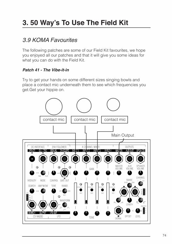
Patch 41 - The Vibe-it-in
Try to get your hands on some different sizes singing bowls and place a contact mic underneath them to see which frequencies you get.Get your hippie on.
Main Output
contact mic contact mic contact mic
75
3. 50 Way’s To Use The Field Kit
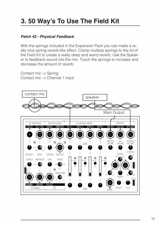
Patch 42 - Physical Feedback
With the springs included in the Expansion Pack you can make a re-ally nice spring reverb-like effect. Clamp multiple springs to the lid of the Field Kit to create a really deep and weird reverb. Use the Speak-er to feedback sound into the mix. Touch the springs to increase and decrease the amount of reverb.
Contact mic -> SpringContact mic -> Channel 1 input
Main Output
contact micspeaker
76
3. 50 Way’s To Use The Field Kit
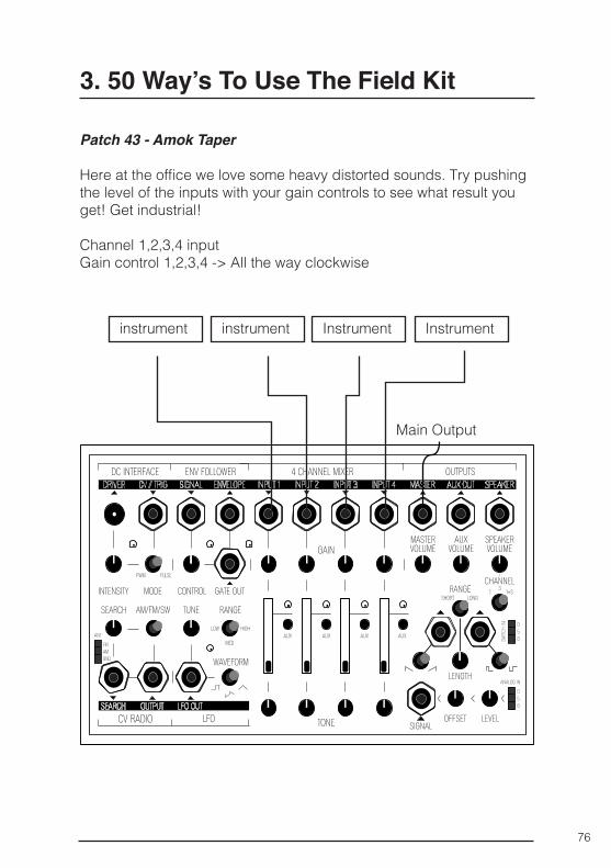
Patch 43 - Amok Taper
Here at the office we love some heavy distorted sounds. Try pushing the level of the inputs with your gain controls to see what result you get! Get industrial!
Channel 1,2,3,4 input Gain control 1,2,3,4 -> All the way clockwise
Main Output
instrument instrument Instrument Instrument
77
3. 50 Way’s To Use The Field Kit
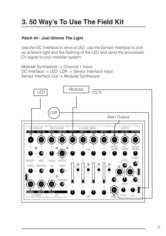
Patch 44 - Just Gimme The Light
Use the DC Interface to drive a LED, use the Sensor Interface to pick up ambient light and the flashing of the LED and send the processed CV signal to your modular system.
Modular Synthesizer -> Channel 1 Input,DC Interface -> LED, LDR -> Sensor Interface Input Sensor Interface Out -> Modular Synthesizer
Main Output
LED ModularCV In
LDR
78
3. 50 Way’s To Use The Field Kit
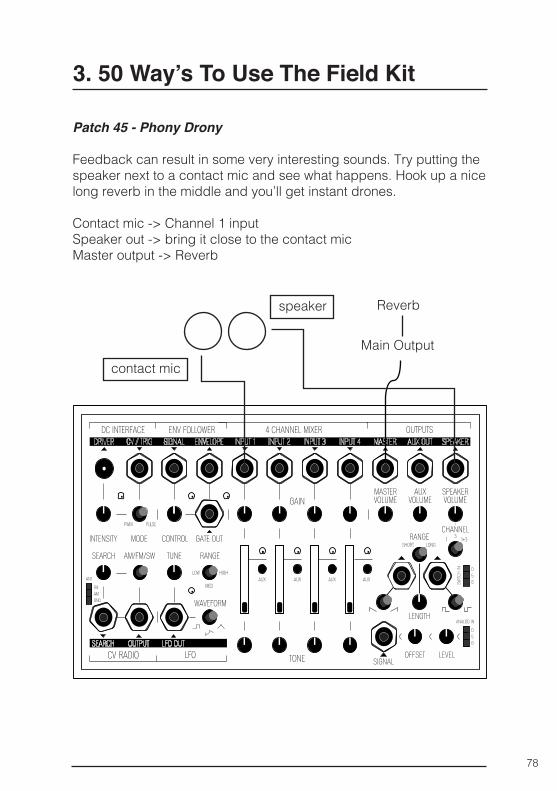
Patch 45 - Phony Drony
Feedback can result in some very interesting sounds. Try putting the speaker next to a contact mic and see what happens. Hook up a nice long reverb in the middle and you’ll get instant drones.
Contact mic -> Channel 1 input Speaker out -> bring it close to the contact micMaster output -> Reverb
Main Output
Reverb
contact mic
speaker
79
3. 50 Way’s To Use The Field Kit
4.0 All Other Patches
The following patches don’t really fit in a category, instead they are meant to give you more ideas to experiment with.
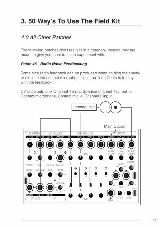
Patch 46 - Radio Noise Feedbacking
Some nice radio feedback can be produced when holding the speak-er close to the contact microphone. Use the Tone Controls to play with the feedback.
CV radio output -> Channel 1 input, Speaker channel 1 output -> Contact microphone, Contact mic -> Channel 2 input
Main Output
contact mic
80
3. 50 Way’s To Use The Field Kit
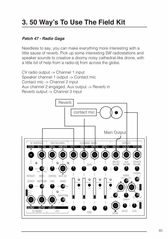
Patch 47 - Radio Gaga
Needless to say, you can make everything more interesting with a little sause of reverb. Pick up some interesting SW radiostations and speaker sounds to creative a doomy noisy cathedral-like drone, with a little bit of help from a radio-dj from across the globe.
CV radio output -> Channel 1 inputSpeaker channel 1 output -> Contact micContact mic -> Channel 2 inputAux channel 2 engaged, Aux output -> Reverb inReverb output -> Channel 3 input
Main Output
contact mic
Reverb

81
3. 50 Way’s To Use The Field Kit
Patch 48 - The Easy Peasy
The signal output of the analog signal interface will always send through voltages, use it to control a cv input manually.
Analog signal interface signal output -> CV inputOffset -> to control the level of voltage
CV input
82
3. 50 Way’s To Use The Field Kit
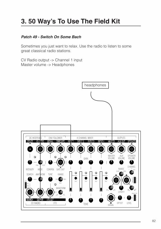
Patch 49 - Switch On Some Bach
Sometimes you just want to relax. Use the radio to listen to some great classical radio stations.
CV Radio output -> Channel 1 inputMaster volume -> Headphones
headphones
83
3. 50 Way’s To Use The Field Kit
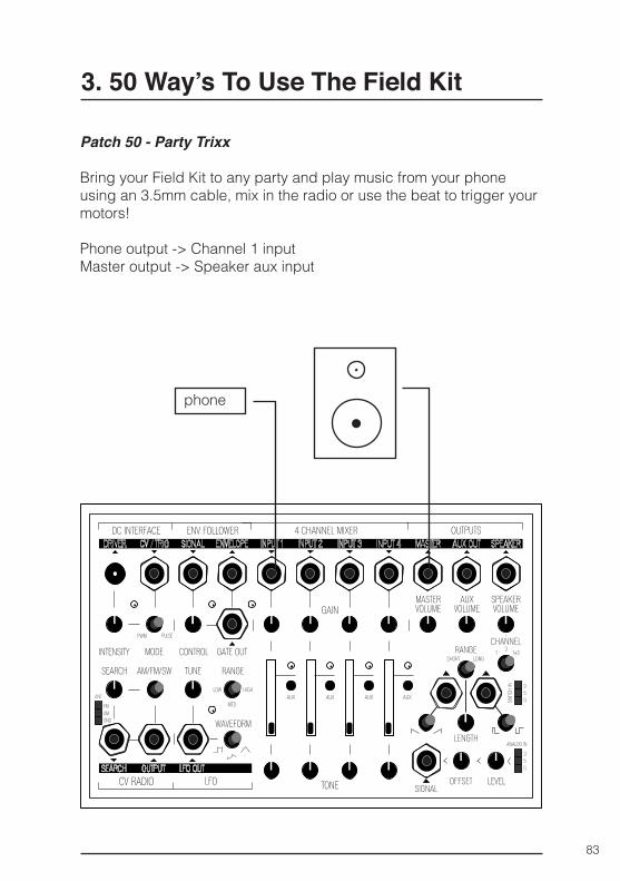
Patch 50 - Party Trixx
Bring your Field Kit to any party and play music from your phone using an 3.5mm cable, mix in the radio or use the beat to trigger your motors!
Phone output -> Channel 1 input Master output -> Speaker aux input
phone
84
4. DIY Manual
General
Hardware
Tools
▪ 1 x Field Kit PCB ▪ 1 x Field Kit front panel ▪ 1 x Field Kit wooden enclosure (bottom + lid) ▪ 4 x bottom pad ▪ 4 x M3 screw.
▪ 1 x horizontal DC connector ▪ 1 x vertical DC connector ▪ 17 x minijack ▪ 17 x nut for minijack ▪ 18 x potentiometer ▪ 4 x small slider potentiometer ▪ 1 x DPDT toggle switch ▪ 3 x SPDT toggle switch ▪ 4 x SP3T toggle switch ▪ 4 x tactile button long shaft ▪ 4 x LED amber ▪ 4 x LED red
▪ soldering iron ▪ drill / screwdriver + M3 head ▪ M8 socket ▪ small clamps
Required Materials
85
4. DIY Manual
Instructions
A. Soldering the hardware
Follow the markings on the PCBs silkscreen to determine where each part goes. Each component only matches its own silkscreen.
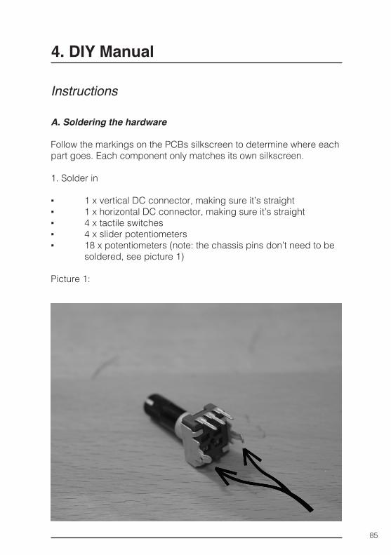
1. Solder in
▪ 1 x vertical DC connector, making sure it’s straight ▪ 1 x horizontal DC connector, making sure it’s straight ▪ 4 x tactile switches ▪ 4 x slider potentiometers ▪ 18 x potentiometers (note: the chassis pins don’t need to be
soldered, see picture 1)
Picture 1:
86
4. DIY Manual
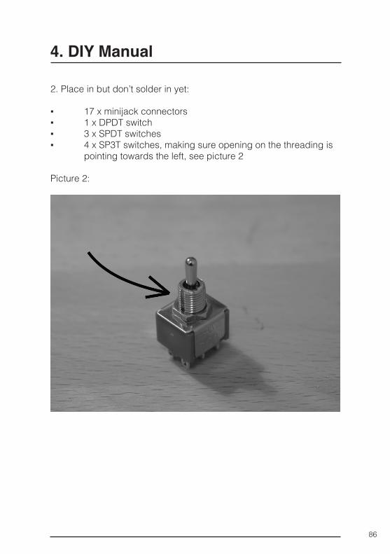
2. Place in but don’t solder in yet:
▪ 17 x minijack connectors ▪ 1 x DPDT switch ▪ 3 x SPDT switches ▪ 4 x SP3T switches, making sure opening on the threading is
pointing towards the left, see picture 2
Picture 2:
87
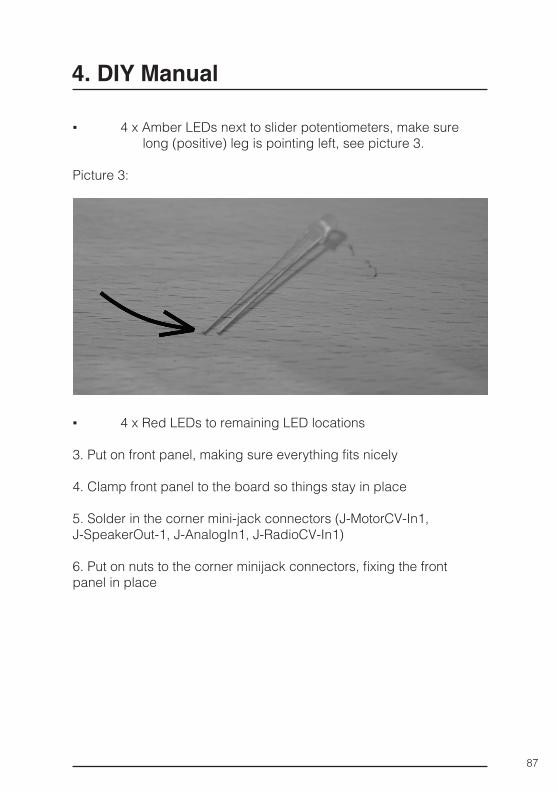
▪ 4 x Amber LEDs next to slider potentiometers, make sure long (positive) leg is pointing left, see picture 3.
Picture 3:
▪ 4 x Red LEDs to remaining LED locations
3. Put on front panel, making sure everything fits nicely
4. Clamp front panel to the board so things stay in place
5. Solder in the corner mini-jack connectors (J-MotorCV-In1, J-SpeakerOut-1, J-AnalogIn1, J-RadioCV-In1)
6. Put on nuts to the corner minijack connectors, fixing the front panel in place
4. DIY Manual
88
7. Take out clamps and continue soldering
▪ The remaining 13 minijack connectors ▪ 1 x DPDT switch ▪ 3 x SPDT switches ▪ 4 x SP3T switches
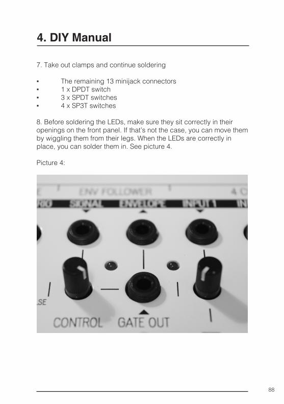
8. Before soldering the LEDs, make sure they sit correctly in their openings on the front panel. If that’s not the case, you can move them by wiggling them from their legs. When the LEDs are correctly in place, you can solder them in. See picture 4.
Picture 4:
4. DIY Manual
89
B. Putting it together
1. Take the PCB off the front panel again.
2. Place the fully soldered PCB inside the wooden enclosure making sure the mounting holes on the PCB align with the pre-drilled holes on the wooden corner pieces.
3. Screw the PCB onto the enclosure using the screws provided with the kit. Use a hand screwdriver for precision.
4. Put the front panel back on the PCB.
5. Screw all the nuts on the minijack connectors.
6. Attach the 4 bottom pads on the bottom corners of the wooden enclosure
Congratulations! Your Field Kit is finished!
4. DIY Manual
90
What type of antennas do I need to use to receive AM, FM and SW frequencies?
▪ Please see chapter: 2.2.3 CV Radio for a good description on how to use different antenna’s with the Field Kit
Does the Field Kit work on a 9V battery?
▪ The Field Kit is designed to work with a 9V power source, so a 9V battery could be used if the user finds a way to connect it to the power input. The Field Kit draws approximately 80mA of current in normal working conditions without driving any external loads, such as an external speaker or a motor. An 8Ω speaker driven with full volume draws up to 220mA of current, while the DC In-terface can draw up to 500mA of current. This adds up to 800mA of current consumption in total which would give the user with a “standard” 9V alkaline battery with 550mAh capacity a usage time of ~ 40 min in full work mode, although the voltage of the battery would drop as it discharges. We are investigating differ-ent ways of powering the Field Kit with a portable solution, keep an eye on our media channels to check the progress!
Can I take my Field Kit in to the world?
▪ Yes! And you should!
What are the dimensions of the Field Kit?
▪ The outer dimensions of the Field Kit in its wooden box with the lid on are 20,0 x 13,0 x 5,2 cm ( ≈ 7,9” x 5,1” x 2,0” ) The avail-able Eurorack panel is 36HP wide.
What specifications are needed for sensors to create signals?
▪ For the Switch In: Any Switch that runs from a supply voltage of 5V. It should give 0V when open and 5V when closed. For the Analog In: any analog sensor that runs from a supply voltage of 5V and outputs a voltage between 0 and 5V.
5. Frequently Asked Questions
91
5. Frequently Asked Questions
Are the inputs mono or could they accept a stereo signal?
▪ All of the inputs on the Field Kit are monophonic, so if a stereo source is connected, the right channel is lost.
Can the inputs/outputs receive/send line level and modular level?
▪ The Field Kit works internally on a unipolar 9V supply and can work with signals up to 6V peak to peak level before clipping. The same counts for inputs and outputs. This is plenty for line level signals with nominal levels of 1V peak to peak and slightly less than the standard modular signal level of 10V peak to peak. A full scale modular signal needs to be slighly attenuated if its to be used with the Field Kit without distortion.
What electronics can be used for the DC Interface besides DC
Motors and Solenoids?
▪ The DC Interface gives out a signal of 9V, up to 500mA, rect-angular signal (steady rectangle in PWM-mode, and pulsed in Pulse-mode). Any piece of electrical devices driven with such signals can be used together with the DC Interface. Examples in-clude computer fans, LEDs, small heaters, small electromagnets, etc. Experiment!
What type of loudspeakers can i connect to the loudspeaker output?
▪ The Loudspeaker output is designed to give out a maximum of 500mW over an 8Ω speaker. A speaker with a higher impedance will also work, but will give out less power (loudness). Doubling the speaker impedance halves the available output power (16Ω -> 250mW, 32Ω -> 125mW, etc.). A speaker with smaller imped-ance than 8Ω is not recommended. The chosen speaker should be spec’ed for at least the following power rating to ensure prop-er operation: 8Ω - 500mW rated power or higher, 16Ω - 250mW rated power or higher and 32Ω - 125mW rated power or higher.
92
5. Frequently Asked Questions
Is the Master Out stereo or mono?
▪ The Master Out is “fake-stereo”, meaning the monophonic output is available from both left and right channels.
Does the Field Kit DIY Version come with a box and frontpanel?
▪ Yes, it does! The front panel of the Field Kit is smaller than a 3U eurorack panel, so if you would like to use the Field Kit with your Eurorack, you can purchase a Eurorack front panel for it from us or make one yourself, we will post the DWG and DXF files for milling and cutting on our website!
Is the DIY Version Difficult to build?
▪ No! All SMT parts are already soldered and there is nothing that needs to be calibrated inside, so its a great project for beginners. We will post videos with instructions online and this manual has a very clear guide for all builders, so we help you with every step!
Where and what type of sensors can I buy?
▪ Some of the sensors that are part of SensorKits for Arduino work very well. The Arduino community in general is a good resource for tips and hints about different types of analog sensors and switches.
93
6. Warranty
KOMA Elektronik warrants its products to be free of defects in mate-rials / workmanship and conforming to specifications at the time of shipment for a period of two years from the date of purchase. During the warranty period any defective products will be repaired or re-placed at KOMA Elektronik’s option on a return-to-factory basis. This warranty covers defects that KOMA Elektronik determines are no fault of the user.
Returning your product
PLEASE DO NOT SHIP US SOMETHING UNSOLICITED.ONLY SHIP AFTER RECEIVING A RMA NUMBER!
You must obtain prior approval in the form of an RMA (Return Material Authorization) number from KOMA Elektronik before returning any product.
Get in touch with us at [email protected] to request the RMA number. All products must be packed carefully and shipped with the KOMA Elektronik supplied power adapter. Sorry, the warran-ty will not be honored if the product is not properly packed.
94
7. Imprint
KOMA Elektronik GmbHWeisestraße 2412049 Berlin-NeuköllnGermany
KOMA Elektronik GmbH is a subsidiary of KOMA Elektronik Holding B.V.
Managing Director: Christian Zollner & Wouter Jaspers Registered Office: Berlin, Germany Court of Registration: Amtgericht Berlin-Charlottenburg Registration Number : HRB 145453 VAT ID: DE285522050

95
8. Who Made The Field Kit PossibleAll of you who pledged for the Field Kit, thanks so much!

96
8. Who Made The Field Kit Possible

97
8. Who Made The Field Kit Possible
98
9. Glossary
AC
▪ AC, or Alternating Current, is a way to determine the flow of elec-trons inside conductors. Alternating Currents flow two-direction-ally, unlike DC or Direct Currents, which flow only in a constant direction.
Amplitude
▪ Amplitude is a property of a signal which determines its magni-tude or change over time.
AM - Amplitude modulation
▪ Amplitude modulation is a technique used for transmitting infor-mation by means of altering the amplitude of a carrier signal. Also used as a synthesis technique.
Attenuation / Attenuator
▪ Opposite of amplification, attenuation is the decrease in power or amplitude of a signal as it travels through a system. An attenuator is a device performing this action.
Audio range
▪ Audio range is the range of frequencies that fall inside the human hearing range. Usually the audio range is determined starting from 20Hz and ending at 20kHz or 22kHz.
AUX - Auxiliary
▪ Aux or Auxilary means additional or supplementary. In an audio context, an auxilary bus or mix is an additional mix of signals alongside the master mix/bus.
99
9. Glossary
Center frequency
▪ Center frequency is a charasteristic of a frequency-dependent system. It determines the middle frequency between it’s lower and upper cutoff frequencies. See also: cutoff frequency.
Clip
▪ Clipping is a form of heavy distortion introduced to a signal trav-elling through a system. Clipping can happen when the signal processing circuitry reaches its amplitude-related operational limits and prevents the processed signal from reaching the max-imum. Clipping can be also introduced deliberately as a sound processing tool.
Coil
▪ Coils are in essense conductors twisted together to form a helix. They transform electric currents into magnetic fields and vice ver-sa. Coils can be used as transducers picking up the alterations in magnetic fields for use as signals inside an electric system. Also, a seminal experimentalist musical duo heavily influencing the avant-garde since the 80s.
Cutoff frequency
▪ Cutoff frequency is a charasteristic of a frequency dependent system. It determines the boundary frequency after which the system starts to attenuate the flow of energy passing through it. See also, center frequency.
CV signal - Control voltage signal
▪ CV or control voltage is a signal used for controlling analogue synthesizers. Even though there are signals specifically designed to be used as control voltages, any form of a varying voltage adheres as a CV source, given it lies inside the operational condi-tions of the target system. See also: gate and trigger.
100
9. Glossary
DC
▪ DC or Direct Current is a way to determine the flow of electrons inside conductors. Direct Currents flow only in a constant direc-tion, unlike AC or Alternating Currents, which flow in two direc-tions.
EQ - Equalizer
▪ EQ or equalization is a type of circuit used for tweaking the spec-tral components of an electric signal.
Frequency
▪ Frequency is a property of a signal which determines the number of cycles per unit of time--also referred to as pitch.
FM - Frequency modulation
▪ Frequency modulation is a technique used for transmitting in-formation by means of altering the frequency of a carrier signal. Also used as a synthesis technique.
Gain
▪ Synonymous to amplification. Applying gain to a signal raises its amplitude or power.
Gate
▪ A gate signal is a pulse-like control signal used together with CV / control voltage signals for controlling analogue synthesizers. See also: CV and trigger.
Hz - Hertz
▪ Hertz is the unit of frequency and is defined as one cycle per second (1/s).
101
9. Glossary
Impedance
▪ Impedance is a characteristic of electrical circuits that deter-mines the circuit’s opposition to current flow.
Offset
▪ Offset is the mean value of an alternating waveform.
Peak-to-peak
▪ Peak-to-peak is an amplitude-related measure which determines the magnitude of a signal by giving the distance between its maximum and minimum points.
Phase
▪ Phase is the position of a point in time on a waveform cycle. It is measured in radians or degrees.
Phase cancellation
▪ Phase cancellation happens when two or more signals with similar frequency components are superimposed, creating a new wave with diminished or increased amplitude where the waves overlap with each other. See also: phase.
Post / Pre-fader
▪ Post- and Pre-Fader are terms used to explain how the contents inside a mixer channel get sent to an external or auxilary bus / mix. If the send path works pre-fader, the amplitude of the signal being sent is not altered when the channels volume fader is ad-justed. If the send path works post-fader, the amplitude is altered as the volume fader is adjusted.
102
9. Glossary
Power
▪ Power, in this case electrical power, is a measure of electrical energy.
Pulse
▪ Pulse is a form of a signal characterized by a fast transient change from its initial steady-state value to an active state, fol-lowed by a fast return to its initial value.
Pulse-width
▪ Pulse-width is a characteristic of rectangular waveforms that determines how long the signal stays in its active state.
PWM - Pulse-width modulation
▪ PWM or pulse-width modulation is a technique used for con-trolling the power transmitted from one part of an electric system to another. Also used as a synthesis tool.
SW - Shortwave
▪ Shortwave is a range of frequencies widely used for transmitting radio broadcasts.
Tilt EQ - Tilt equalizer
▪ A tilt equalizer is a form of equalizer used for emphasizing one end of the spectral content of a signal while attenuating the other.
Transducer
▪ Transducers are electronic devices that convert energy from one form to another. Transducers include: microphones which convert variations in air pressure into electric signals, and electric motors, which convert electric signals into mechanical force.

103
9. Glossary
Trigger
▪ A Trigger is a control signal resembling a gate signal with a fast transient change from its initial state to a high or low value and a fast return to its initial state. Unlike the gate signal, the trigger doesn’t stay on its active state but immediately returns to its initial value.
104
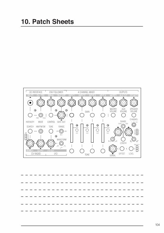
10. Patch Sheets