5000 iom y 0003_0 tpcdr approved
DESCRIPTION
UPSTRANSCRIPT


Uninterruptible Power Supply Manual EFFEKTA MH5000/7000
Supplier Document
Part: UPS MH 5000/7000
Supplier: Effekta
Title: Installation and Maintenance Manual
Vendor Document Number: A11000139
Archived as: X-065438-01-60
This document is not under CAMERON revision control.

Uninterruptible Power Supply Manual EFFEKTA MH5000/7000
MH Series 5/7KVA 230V Uninterruptible Power System
User’s Manual
Edition November 2001 P/N A11000139

Uninterruptible Power Supply Manual EFFEKTA MH5000/7000
Legal Notices The information in this document is subject to change without notice. EFFEKTA makes no warranty of any kind with regard to this manual, including, but not limited to, the implied warranties of merchantability and fitness for a particular purpose. EFFEKTA shall not be held liable for errors contained herein or direct, indirect, special, incidental or consequential damages in connection with the furnishing, performance, or use of this material. EFFEKTA Regeltechnik GmbH, Klausenburger Str. 9, 88069 Tettnang, Germany

Uninterruptible Power Supply Manual EFFEKTA MH5000/7000
Warranty All EFFEKTA instruments are warranted against defects in material and workmanship for a period of one year after date of shipment. EFFEKTA agrees to repair or replace any assembly or component found to be defective, under normal use during this period. EFFEKTA obligation under this warranty is limited solely to repairing any such instrument, which in EFFEKTA's sole opinion proves to be defective within the scope of the warranty when returned to the factory or to an authorized service center. Transportation to the factory or service center is to be prepaid by the purchaser. Shipment should not be made without prior authorization by EFFEKTA This warranty does not apply to any products repaired or altered by persons not authorized by EFFEKTA, or not in accordance with instructions furnished by EFFEKTA. If the instrument is defective as a result of misuse, improper repair, or abnormal conditions or operations, repairs will be billed at cost. EFFEKTA assumes no responsibility for its product being used in a hazardous or dangerous manner either alone or in conjunction with other equipment. High voltage used in some instruments may be dangerous if misused. Special disclaimers apply to these instruments. EFFEKTA assumes no liability for secondary charges or consequential damages and in any event, EFFEKTA´s liability for breach of warranty under any contract or otherwise, shall not exceed the purchase price of the specific instrument shipped and against which a claim is made. Any recommendations made by EFFEKTA for use of its products are based upon tests believed to be reliable, but EFFEKTA makes no warranty of the results to be obtained. This warranty is in lieu of all other warranties, expressed or implied, and no representative or person is authorized to represent or assume for EFFEKTA any liability in connection with the sale of our products other than set forth herein. EFFEKTA Regeltechnik GmbH Klausenburger Str. 9 88069 Tettnang Tel: +49 07542-9353300 Fax: +49 07542-9353-300 www.effekta.com

Uninterruptible Power Supply Manual EFFEKTA MH5000/7000
WARNING This equipment has been tested and found to comply with the limits for Class A computing device pursuant to Subpart J of Part 15 of the FCC rules. These limits are designed to provide reasonable protection against harmful interference when the equipment is operated in a commercial environment. The equipment generates, uses, and radiates radio frequency energy and, if not installed and used in accordance with the instruction manual, may cause harmful interference to radio communications. Operation of the equipment in a residential area is likely to cause interference in which case the user at his own expense will be required to take whatever measures to correct the interference. The information in this document is subject to change without prior notice in order to improve reliability, design and function and does not represent a commitment on the part of the manufacturer. Under no circumstances will the manufacturer be liable for direct, indirect, special, incidental, or consequential damages arising out of the use or inability to use the product or documentation, even if advised of the possibility of such damages. ©Copyright 2001 All rights are reserved. No part of this document may be reproduced in any way without written permission.

Uninterruptible Power Supply Manual EFFEKTA MH5000/7000
vii
Table of Contents 1. OVERVIEW.................................................................................................. 1-1 1.1 Product Introduction............................................................................................... 1-1 1.2 Features................................................................................................................... 1-1 1.3 Safety Consideration............................................................................................... 1-2 1.4 Functional Explanations ......................................................................................... 1-3 1.5 Front / Rear Panel ................................................................................................... 1-5 1.6 Display.................................................................................................................... 1-7
2. INSTALLATION........................................................................................... 2-1 2.1 Precaution ............................................................................................................... 2-1 2.2 Inspection................................................................................................................ 2-1 2.3 Setup ....................................................................................................................... 2-2 2.3.1 Placing the UPS .................................................................................................. 2-2 2.3.2 Providing Power Utility ...................................................................................... 2-5 2.3.3 Power Connection............................................................................................... 2-6 2.3.4 Control Port......................................................................................................... 2-7 2.3.5 RS-232C Port ...................................................................................................... 2-8 2.3.6 Extended Battery................................................................................................. 2-9 2.3.7 Configuration Switch .......................................................................................... 2-9 2.3.8 Maintenance Switch.......................................................................................... 2-11 2.3.9 Output Breaker.................................................................................................. 2-12 2.3.10 Sizing Your Load............................................................................................ 2-12 2.3.11 Maintenance.................................................................................................... 2-12
3. OPERATION................................................................................................ 3-1 3.1 Introduction ............................................................................................................ 3-1 3.2 The Flowchart of Operation ................................................................................... 3-1 3.3 Checking the List before Power-On ....................................................................... 3-2 3.4 Power-On................................................................................................................ 3-2 3.5 Cold Start................................................................................................................ 3-3 3.6 Displaying Measurement........................................................................................ 3-3 3.7 Fine Tune................................................................................................................ 3-4 3.8 Automatic Shutdown .............................................................................................. 3-4 3.9 Automatic Restart ................................................................................................... 3-4 3.10 Automatic Bypass ................................................................................................. 3-5
4. SPECIFICATIONS ....................................................................................... 4-1 4.1 System Specification .............................................................................................. 4-1 4.2 Battery Run Time Chart ......................................................................................... 4-3
5. TROUBLESHOOTING................................................................................. 5-1

Overview
1-1
1. Overview
1.1 Product Introduction The Uninterruptible Power System provides you with the advanced technology in the modern world to protect computer equipment, telecommunication instrument, electrical facilities, medical equipment, and any other important equipment from corruption or loss of data due to power line disturbance. The design philosophy of power stage is through the combination of a Double-Conversion circuit to create continuous power for the load. It offers complete protection against a variety of power problems, power down, brownout, electrical noise, spikes, sags, lightning surges, voltage transient, and frequency variation.
1.2 Features ■ DSP (Digital Signal Processing) Controller
The state-of-art DSP controller supplies pure and stable power for 2% distortion and1% regulation. DSP monitors the output condition of UPS in real time, and gives excellent transient response after its comparison with the smart program. The significant change digitizes the traditional circuit to make it fast and more accurate, lowers the quantity of parts, and solves the problem of degeneration to enhance the reliability.
■ IGBT (Isolated Gate Bipolar Transistor) Module The UPS is designed with IGBT module. It is highly reliable, small in volume, and fit for big current.
■ PFC (Power Factor Correction) PFC technology plays an important part in the UPS. It keeps the load-generated harmonics from reflecting back into your line source. The reflected harmonics in areas consisting of a high concentration of non-linear loads is harmful to other power devices or systems. The UPS meets the concept of green power, for it isolates the fluctuation of load effectively, and avoids polluting the line source.
■ APLL (Advanced Phase Lock Loop) APLL can be automatically synchronized to the frequency of line power, and tracks continuously within the range. When the fluctuation of input frequency is larger than the default, the system will leave phase lock so as to supply stable frequency to the load. Hence, the equipment will be protected from fast frequency fluctuation.
■ Cold Start When input has no line voltage, or requires the supply of different frequency, the internal batteries in the UPS will provide spare power for output. ■ Auto Shut Down / Auto Restart In battery mode, and under the circumstance of lower battery voltage, the UPS will be powered off automatically in order to prevent over discharge. However, if the line voltage recovers and auto restart is enabled, the UPS will be powered on by itself again. ■ Automatic / Maintenance Bypass

Uninterruptible Power Supply Manual EFFEKTA MH5000/7000
1-2
Under some special circumstances such as overload, protection or failure, the main power supply will switch to load via the built-in bypass circuit automatically. During maintenance, the UPS can be cut off manually through the maintenance bypass switch on the rear panel. Thus, power is directly supplied by the input side.
■ Fan Speed Control In order to control the noise figure around the site, a built-in CPU will regulate the speed of the fan automatically in accordance with the internal temperature and the amount of output power.
■ Graphic LCD Display This exclusively developed LCD is a device with display of high contrast. The user-friendly device coordinates with graphs to indicate the system’s internal operation.
■ Measurement The UPS is capable in simple measurement. You can directly observe the power status on the LCD which displays input/output voltage, current, power and frequency according to your need.
■ Battery Remaining Time In battery mode, the UPS can calculate the remaining time for your reference.
■ Battery Supervision The internal battery program will manage the batteries’ charge and discharge so as to prolong the battery life.
■ Compact Fine technological design has created an amazing power density for the UPS. The UPS meets the height of 28″. It can be put under the desk easily, and its elegant appearance has become one of the OA designs.
■ Self-Diagnosis Here the CPU is used to monitor the system’s operation. When the system is in ON/OFF or other protection modes like OCP, OVP, OPP, OTP, or its parts are out of order, the CPU will take measures to do safety management. Meanwhile it will show the error code on the LCD to remind you or maintenance personnel of the failure or error.
1.3 Safety Consideration
IMPORTANT SAFETY INSTRUCTIONS
Safety Symbols
It indicates hazardous voltage. It indicates ground terminal.

Overview
1-3
It indicates instructional manual symbol.
CAUTION It indicates attention to an operating procedure. + WARNING It indicates attention to a procedure and practice. The following general safety precautions must be observed during operation, service and repair. ■ Do not remove covers. The system is to be serviced by qualified service personnel only. ■ The protective earth or ground terminal must be connected to ground. ■ High leakage current! Earth connection is essential before connecting supply. ■ Install in a temperature and humidity controlled indoor area which is free of conductive
contaminants. ■ The UPS receives power from more than one source. Disconnection of the AC power, the
external battery connection, and the internal battery fuse is required to de-energize the unit before servicing.
■ Hazardous live parts inside the UPS are energized from the battery supply even when the input AC power is disconnected.
■ Battery circuit is not isolated from the AC input. Hazardous voltage may exist between battery terminals and ground.
■ Mishandling of batteries may cause high energy and chemical hazard. ■ Lead acid batteries may cause chemical hazard.
1.4 Functional Explanations By use of Double Conversion and DSP technology the UPS provides you with the best power. Basically, the system is designed into three modes of operation: NORMAL, BATTERY, and BYPASS. Each mode supplies power to the load for continuous service. In NORMAL mode, AC line power is filtered by EMI filter to reduce spike and noise. Then, it is passed to a converter. The converter rectifies and regulates the AC to a stable DC for inverter power. In the meantime, it forces the input current to follow the input voltage dynamically so as to ensure a sinusoidal input current waveform and near unity power factor. The inverter operating from DC power by a combination of pulse width modulation (PWM) re-constitutes a sine wave of low distortion which is driven by DSP in real time sampling and its comparison with the smart program. When an AC fails or falls out of the specified limits, the mode of operation will switch to BATTERY mode. In BATTERY mode, the AC rectification and charge capabilities of the UPS will become inactive. The system will operate in this mode until the batteries lower the limits. It depends on the capacity of the batteries. When power line recovers, the UPS will delay for a period of time. Then, it will be back to NORMAL mode as the AC power falls within the specified limits again.

Uninterruptible Power Supply Manual EFFEKTA MH5000/7000
1-4
In BYPASS mode, the UPS switches from the power to AC line automatically to ensure continuous power to the load. On an extreme condition or malfunction, the UPS will stay in BYPASS mode, or attempt to return to NORMAL mode. It depends on the condition of falling within the specified parameters.
Figure 1-1 System Block Diagram
AUTOMATICBYPASS
EMI FILTER&
SURGESUPPRESSION
ACIN
CONVERTERWITHPFC
INVERTER EMIFILTER
ACOUT
BATTERY BATTERYCHARGER
CONTROL CENTER
CPU DSP COMMUNICATION
INTERFACE
CONTROLIN/OUT

Overview
1-5
1.5 Front / Rear Panel Front View
Figure 1-2 The Front Panel of UPS
Power Switch
Graphic LCD
Buzzer Switch
Air Intake

Uninterruptible Power Supply Manual EFFEKTA MH5000/7000
1-6
Rear View
Figure 1-3 The Rear Panel of UPS
Marking Label
Hardwired Terminal
Control Port RS-232C Port
Cooling Fan
Maintenance Switch
Output Breaker
Buzzer Key
Configuration Switch
Caution Label
Warning Label

Overview
1-7
1.6 Display
Figure 1-4 The LCD NORMAL MODE : The UPS is working in normal mode. The UPS provides stable power within the specification through the inverter to output. BATTERY MODE : The UPS is working in battery mode. The UPS provides stable voltage within the specification through the inverter to output. When the indicator is blinking, it means that the batteries need changing. BYPASS MODE : During power-on or when protection occurs, the UPS will enter into bypass mode.
Multi-function Meter & Error Message
Power
Frequency
Time
Input Status
Output Status
Buzzer Status
Charge Status
Over Load
Bypass Mode Normal Mode
System Fault
Load Condition
Battery Condition
Battery Run Time
Ampere
Voltage
Battery Mode

Uninterruptible Power Supply Manual EFFEKTA MH5000/7000
1-8
FAULT : It means system failure (see error codes). The system may be in Bypass Mode, Output Off or Shutdown. CHARGE : The batteries are on charge. OVER LOAD : The output current or power is in the status of overload. When light is steady, the over load is 101% ∼ 124%. When light is blinking, the over load is 124% ∼ 150%. BUZZER STATUS : The buzzer is disabled when the indicator is lighted. LOAD BAR : Five segments indicate the percentage of output power. ≥10% ≥30% ≥50% ≥70% ≥90% BATTERY CAPACITY : Five segments indicate the percentage of battery capacity. 10% 30% 50% 70% 90% REMAINING TIME : In battery mode count down the remaining battery capacity by minute. The data are for reference only due to the battery’s type, brand, life, temperature, and error made during discharge. In use of the extended battery bank time calculation will be inaccurate. XX.X min means the remaining time of discharge. INPUT VOLTAGE : XXX V means the input voltage. INPUT CURRENT : XX. X A means the input current. INPUT POWER : X.X Kw means the actual input power. INPUT FREQUENCY : XX.X Hz means the input frequency. OUTPUT VOLTAGE : XXX V means the output voltage. OUTPUT CURRENT : XX.X A means the output current. OUTPUT POWER : X.X Kw means the actual output power. OUTPUT FREQUENCY : XX.X Hz means the output frequency.

Installation
2-1
2. Installation
2.1 Precaution This manual contains IMPORTANT SAFETY INSTRUCTIONS, so please KEEP THE INSTRUCTIONS for future reference. ■ Safety Precautions
Read the safety precautions carefully before installing the UPS. ■ Do not remove the covers
Only qualified personnel can remove the covers. For internal inspection or maintenance contact your nearest sales representative.
■ Ventilation Openings Do not block the ventilation openings and open the covers during operation, because this will cause malfunction when temperature rises.
■ In case of malfunction Never keep using the UPS if you find any symptom of malfunction such as unusual sound, smell or smoke coming from the cabinet.
■ Cleaning Please inspect or clean the front panel, rear panel, and the cooling fan regularly. Disconnect the power line first before you clean the case or any other part of the UPS.
■ Never install in any of the following places − where temperature and humidity are out of specification. − where the sunlight is direct, or the heat sources are near. − where an excessive amount of soot, steam, dust, or corrosive gases are present. − where high voltage or strong magnetic field sources are near. − where is unstable.
■ Avoid using unbalanced load, half rectifier, or motor load such as dryer, starter, etc.
2.2 Inspection After receiving the package of UPS, please inspect it according to the following points, and take actions if necessary. 1. Inspect if the packing material is broken, polluted and affects the machine. 2. Unpack the machine carefully and inspect it. If you find the machine is damaged, please
keep the packing material, notify the carrier at once, and contact the nearest agent or distributor for appropriate management.
3. Check if the items and amount are correct according to the purchase receipt.

Uninterruptible Power Supply Manual EFFEKTA MH5000/7000
2-2
2.3 Setup The setup can be basically divided into two parts, physical part (see 2.3.1) and electrical part (see 2.3.2, 2.3.3, 2.3.4, 2.3.5, 2.3.6, 2.3.7, 2.3.8, 2.3.9, 2.3.10). Please install in accordance with following steps. + WARNING The installation must be done by well-qualified personnel authorized by the manufacturer.
2.3.1 Placing the UPS Push the UPS into the location as suggested in Figure 2-1, and make sure that the air circulation is good enough.
Figure 2-1 The Top View of Installation
■ The base must be flat, hard, and can bear the weight of the UPS. ■ The temperature in the environment for operation is from 0°C to 40°C.
The humidity in the environment for operation is from 10% to 90% (non-condensing). The temperature for storage is from −20°C to 60°C.
■ If there is one or more than one extended battery banks (optional), please do the joining by use of the accessories.

Installation
2-3
1. Standard Unit: the combination of the UPS and the fixed base Push the UPS onto the base. Combine the UPS and the fixed base by fixing the four screws on the front and rear
parts of the base. Fix the eight screws on either side of the foot stock.
Figure 2-2-a The UPS and the Fixed Base
Figure 2-2-b The UPS and the Fixed Base
2. Extended Battery Bank: the Combination of the UPS and the fixed base with battery bank Fix the two screws on the two bases. Push the UPS and the battery bank onto the base. Combine the UPS and the battery bank by fixing the eight screws on the two bases. Fix the two fixed pieces on the rear part (unscrew the original cabinet side board). Fix the eight screws on either side of foot stock.

Uninterruptible Power Supply Manual EFFEKTA MH5000/7000
2-4
Connect by repeating the above ways if there are more than two units.
Figure 2-3-a The UPS and the Fixed Base with Battery Bank
Figure 2-3-b The UPS and the Fixed Base with Battery Bank

Installation
2-5
Figure 2-3-c The UPS and the Fixed Base with Battery Bank
2.3.2 Providing Power Utility ■ The system adopts the single phase 3-line power source (1∅, 2W + GND). ■ Choose a suitable power cord in accordance with the norm of UL or IEC, and do the
corresponding management. 1. Wire size: > 8 AWG or > 6mm2, 105°C 2. Wire type: SO, SOO, ST, STOO, SJ, SJO, or SJOO. 3. Wire conductors: 3 (Line, Neutral, Ground). 4. Using copper wire only. ■ For safety add a breaker to the main power source and input branch as the following
figure shows.
Figure 2-4 The Power Utility

Uninterruptible Power Supply Manual EFFEKTA MH5000/7000
2-6
The Table of Input Current & Breaker 7KVA 5KVA Max Input Current 38.0A 28.0 Current Breaker 50A 40A
CAUTION
To reduce the risk of fire, connect over current protection in accordance with the National Electrical Code ANSI/NFPA 70. ■ The measured AC voltage between neutral and ground should be below 30Vac, otherwise
improve the quality of grounding. + WARNING
Any disconnection of this ground system will cause a potential shock hazard to operating personnel.
2.3.3 Power Connection 1. Unscrew the four screws of M3 outside the wire box on the rear panel. 2. Connect the input power source correctly to L, N and G of input at the left of terminal,
and fix them securely. 3. Connect the output power source to the right of terminal as mentioned above. 4. If a remote battery bank is installed, please refer to 2.3.6. 5. Close the wire box, and recover the unscrewed screws.
CAUTION UTIO
Figure 2-5 The Power Connection

Installation
2-7
CAUTION 1. Every polarity must be correct to avoid risk of shock and system damage. 2. Remove or disconnect power source before doing any connection. 2.3.4 Control Port Contact Closure Relay The UPS provides an internal relay through a 9-pin, D-SUB connector (DB-9) for signal input and output. It can be connected to your computer, local area network (LAN), and control system. You can accomplish the wire connection by using accessories or making them by yourself according to Figure 2-7.
Pin Definition Description Pin 1: UPS OFF When UPS makes inverter OFF due to all kinds of
protection. Pin 2: INPUT FAIL When input power does not meet input conditions. Pin 3: BYPASS When UPS is in BYPASS MODE. Pin 4: COMMON It is the common of all pins. Pin 5: LOW BATTERY When the voltage of the battery inside UPS is too low.
The normal status of relay is OFF (open), but will be ON (close) when any of the conditions occurs. ■ The length of the control line ought not to exceed 50 meters. ■ The rating of relay contact: Voltage: 250 Vac or 28 Vdc Max Current: 1 Amp Max ■ The contact relay and control circuit are electrically insulated from the UPS. Emergency Power Off For safety, through the external customer-supplied switch the UPS can be remotely powered off by the operator during emergency or under special circumstances.

Uninterruptible Power Supply Manual EFFEKTA MH5000/7000
2-8
Figure 2-6 Remote EPO Installation ■ Pin definition
Pin 7 : Common. Pin 8 : External switch for EPO function. ■ Switch type
A momentary contact switch larger than capacity of 120V/100mA and color-coded with red push-button at a yellow background.
■ Switch device must be clearly marked with Emergency Power Off, and placed for easy access.
■ The extra components like switch, wire, connectors are customer-supplied. + WARNING Do not add voltage to pin 7 and pin 8. The voltage is about 9 V when the circuits of EPO and shutdown control port are open.
2.3.5 RS-232C Port By connecting the standard RS-232C port of the UPS with IBM compatible PC or the remote card of SNMP through the optional accessories you can transfer the data (see Figure 2-7). Communication Settings
Control Setting Baud Rate 2400 Data Bits 8

Installation
2-9
Parity None Stop Bit 1
CAUTION
Make sure that the UPS and the PC are power-off before connecting cable.
2.3.6 Extended Battery The UPS can extend the backup time by additional battery bank (optional).
CAUTION In order to avoid the risk of electrical shock, the installation of extended battery bank must be done by well-qualified service personnel. 1. Unscrew the four screws of M3 outside the wire box on the rear panel. 2. Remove the cover sheet of battery cable additionally added to the wire box. 3. Connect the extended cable of battery bank to the wire box. 4. Before installing the extended battery, measure the difference between the battery voltage
inside the UPS and the extended battery voltage.
CAUTION If the difference between the battery voltage inside the UPS and the extended battery voltage is too large, the joining may cause risk of shock and inrush current, and thus spoil the connector. 5. When the difference of voltage reaches more than 2 Vdc, you can turn on the UPS to
charge so as to raise the internal battery voltage, or turn off AC power to make the UPS enter into Battery Mode to consume the internal battery voltage. Only the value of voltage becomes the same can joining be done.
6. Recover the cover sheet of the wire box, and fix the screws.
2.3.7 Configuration Switch When the UPS is turned on, it will detect the configuration of CONFIG SW on the rear panel to initiate the working mode.
CAUTION The configuration switch must be re-configured by qualified service personnel. Wrong configuration will bring malfunction, or damage other equipment.

Uninterruptible Power Supply Manual EFFEKTA MH5000/7000
2-10
1. Remove the two screws and the cover sheet of CONFIG SW. 2. Adjust the configuration of CONFIG SW according to the actual need and function (see
Figure 2-7). 3. Recover the cover sheet and fix it.
Figure 2-7 The Control Port, RS-232C Port and the Table of Configuration SW

Installation
2-11
+ WARNING Any change of setting will take effect after the UPS is restarted.
The Definition of Configuration Switch
SW 1: System On The switch is designed to protect the UPS from wrong touch of switch in transportation. Only when the switch is ON can the system work normally (the default is OFF).
SW 2: Fine Tune When the switch is ON, you can adjust output voltage up or down in coordination of the buzzer switch.
SW 3: Cold Start Under the circumstance of no input AC power, if you want to output AC power by starting the batteries inside the UPS, you can set the switch to ON. But when AC power meets the conditions of input, the function is ineffective.
SW 4: Frequency When the conditions of cold start are established, you can choose 50 or 60 Hz as the output frequency according to this switch (for cold start only).
SW 5: Synchronized Range Select the Sync frequency between input and output. (In an area where frequency is unstable, you can choose the range of 3 Hz, whereas in an area where the fluctuation of frequency is sensitive or higher frequency is required, you can choose the range of 1 Hz).
SW 6: Voltage Select (Bit 3) Choose the fit range of output voltage in coordination with the combination of these three switches.
SW 7: Voltage Select (Bit 2) SW 8: Voltage Select (Bit 1)
CAUTION Set right voltage you need before operation. 2.3.8 Maintenance Switch Maintenance switch is on the rear panel. It is a manual bypass switch for inspection, repair, change of batteries, etc. Normally, it is in the position of UPS, but when any of the situations mentioned above happens, it will be switched to that of BPS.

Uninterruptible Power Supply Manual EFFEKTA MH5000/7000
2-12
Figure 2-8 The Maintenance Mode Figure 2-9 The UPS Mode
CAUTION The switching of maintenance switch must be done by authorized or service personnel. Only when the input voltage has been removed and the UPS is OFF can the switching be done. Capacity of maintenance switch is 25A rms. 2.3.9 Output Breaker The output breaker is designed to protect the UPS against damage caused by over load or short circuit from the equipment. It is set to ON before use.
CAUTION When circuit breaker trips, please inquire of the reason first, then turn it on. 2.3.10 Sizing Your Load This subsection describes how to calculate the load capacity of each equipment, and how to make the best use of the UPS. Calculating the total dissipation power of equipment is a quite important job for the output of the UPS. The job determines whether the operation is normal or not. You can read the values of VA on the nameplates of used electric products. If the values are in Watt, multiply them by 1.43, and they will be in VA. Add all values of VA or Watt, and make them within the specification (example: 7KVA / 4.9KW) The UPS is designed to operate in any extreme condition. For future expansion, the inrush power upon power-on, and the extension of the product’s life, you are recommended to make the total power after calculation about 70% of the output power of the UPS.
2.3.11 Maintenance 1. Cleaning
■ Please clean the panels and the machine with non-volatile liquid and soft cotton cloth. ■ Inspect the cleanness of the air intake regularly, and clean it with a vacuum cleaner.
2. Maintenance Basically, except the protection, inspection and change of batteries there is nothing particular in the UPS system requiring maintenance. Usually, a newly purchased set of batteries can last for three to five years. It depends on the type of battery, the operation condition of the UPS, the environment, etc. Accordingly, the maintenance of batteries is
Installation
2-13
essential, and must be done by qualified technicians or service personnel only. a. If you do not use the UPS for a long period of time, you have to power it on and
charge for more than four hours every three months. b. Before using the UPS, power it on and charge for four hours. During charge you still
can use the UPS. But if there is a blackout at the same time, the time of that charge may be less than standard value.
c. Normally you should charge/discharge the batteries once every four to six months. Discharge till power-off and then charge. The time of charge for a standard UPS must not be less than four hours every time.
d. In areas of high temperature you should charge/discharge the batteries every two months. The charge for a standard UPS must not less than four hours every time.
3. Battery Replacement + WARNING For safety, in change of batteries you have to contact the dealer, and let service personnel do it. Do not change alone.
■ Do not dispose of batteries in a fire, for it may explode. ■ Do not open or mutilate batteries, for the electrolyte is toxic to skin and eyes. ■ Recycle properly according to the local codes on the batteries. ■ The batteries must be replaced with the same type and rating. ■ The batteries fit for use include:
YUASA NP7-12\250 CSB GP 1272 F2 PANASONIC LCR 12V 7.2S1 HITACHI HV7-12 F2 SUNRISE LCR 12V 7.2P1
■ Hazardous voltage may exist between battery terminals and ground. Test it before touching.
4. Replacement Procedures
■ Power off the UPS and input power. Remove the wiring and signal connectors of the input and output power of UPS.
■ Open the cabinet cover and cabinet sides of UPS rightly according to Service Manual. ■ Remove the connector between the batteries and the converter PCB (P8-1, P9-1). ■ Remove three battery holders (5/7 KVa). There are some differences between the
numbers of batteries. ■ Remove the connecting wires between batteries one by one. Notice that the wiring in
the front and back rows is different. ■ Pull out old batteries (do not make polarity short circuit), recycle them, and get the
new batteries and insulating plate. ■ Connect the batteries according to the wiring graph in Service Manual. Notice that the
wiring in the front and back rows is different, and all batteries are in series. ■ Replace the three battery holders, and measure the voltage between P8-1 and P9-1
within ±10% of the specifications (refer to Chapter 4). ■ Connect P8-1 and P9-1 back to PCB. Notice that if polarity is not right, components
will be burned. Small sparks inside batteries and PCB connectors are normal. ■ Replace the outer cabinet, and recover the original wiring.

Operation
3-1
3. Operation
3.1 Introduction In order to make the UPS appear user-friendly, only one power switch is designed on the front panel. Under the operation of a microcomputer, the UPS offers the functions such as Mode Transfer, Feed Back, Control Display, Communication, and Protection automatically. Once the UPS is powered on, it will act as a guard to protect your equipment from lots of power problems. This chapter guides you how to use the UPS step by step.
3.2 The Flowchart of Operation
Figure 3-1 The Flowchart of Operation
The flowchart varies in accordance with the purpose of design and improvement. This unit can be operated by any individual with no previous training.
: Status
: Happening
Power Switch On
Bypass Mode
Self-CheckAC Restart
Normal StartCold Start
Battery Mode
AC Fail
Normal Mode
Bypass Mode
SystemShutdown
Power Switch Off
UPS FailUPS Fail
Fatal ErrorFatal Error
AC Back

Uninterruptible Power Supply Manual EFFEKTA MH5000/7000
3-2
3.3 Checking the List before Power-On The UPS is designed to avoid failure or damage caused by artificial mistakes as much as possible. Since wrong setting, operation and use will result in danger, you must check the following list before power-on.
Checkpoint Result ■ Is the Input/Output polarity correct? ■ Are the Input/Output cables secured? ■ Is the Input/Output grounding correct? ■ Has the wiring of options been completed and tested? ■ Has the output voltage been set? ■ Has Sync Range been set? ■ Has Cold Start been set? ■ Has SW 1 System-On been started? ■ Is Maintenance SW in the position of UPS? ■ Is output circuit breaker On?
3.4 Power-On
CAUTION Before pressing the power switch, it is supposed that you have done correct setting. 1. Press the power switch on the front panel. 2. The system does the self-check automatically. Check if every segment of LCD moves normally. Check if the buzzer sounds normally. Check if the highest speed of the fan is normal. 3. LCD shows the software versions of DSP and CPU. 4. LCD shows the value of input voltage. The UPS enters into Bypass Mode to supply power
to the load, and traces the input frequency to do synchronization. 5. When AC power meets the fit conditions and finishes synchronization, LCD will show the
value of output voltage, and the UPS will enter into Normal Mode.
CAUTION The backup time for Battery Mode will be reduced if batteries are not fully charged.
Operation
3-3
3.5 Cold Start 1. The use of cold start must meet the following conditions. There is no AC power, or the power exceeds the input specification. SW 3 of Configuration SW is in the position of ON (Enable). 2. Execute the first two points on section 3.4. 3. When self-check is completed, and the conditions of cold start are met, the UPS will
switch to Battery Mode automatically.
CAUTION
The UPS will switch to Normal Mode automatically when the system is started by cold start, the line power recovers, and meets the conditions of input as well as same frequency. If the input frequency is different from the set one, the UPS will stay in Battery Mode with the initial frequency.
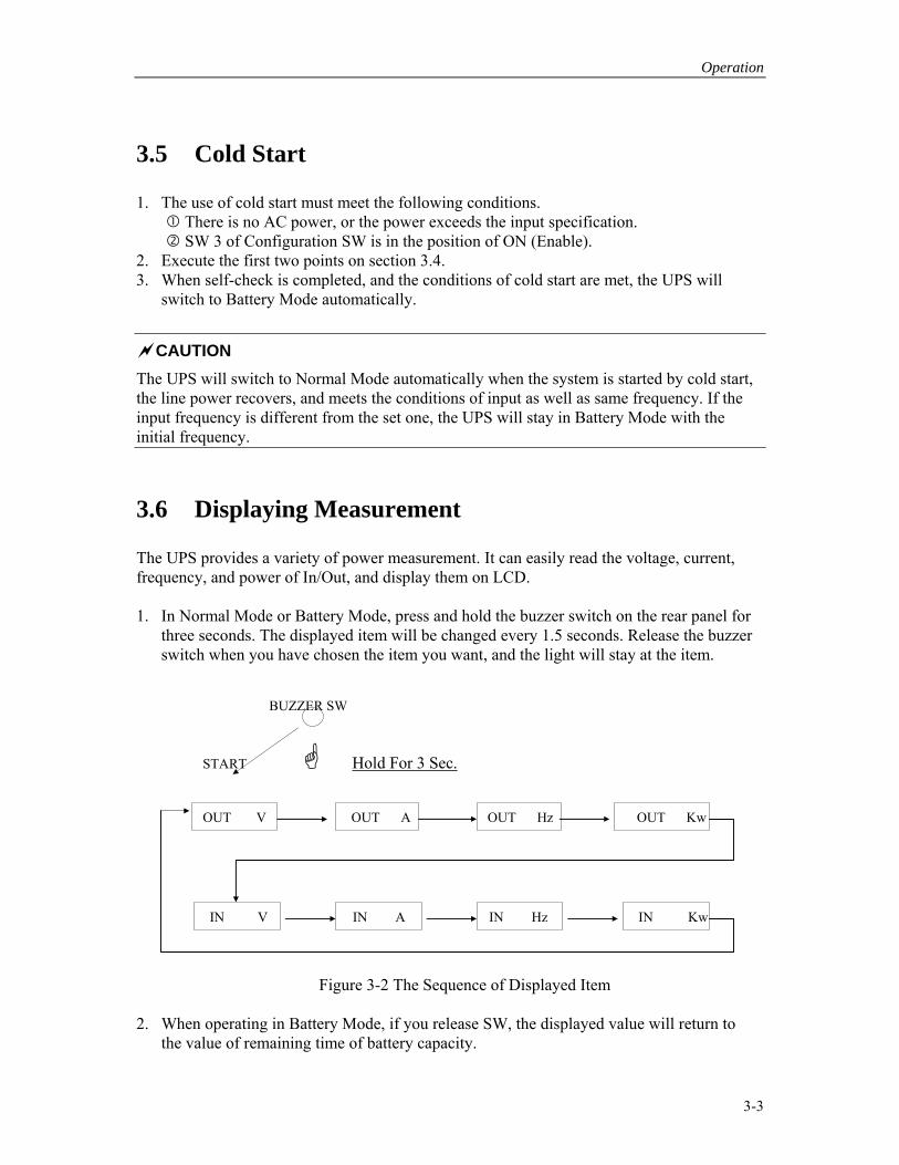
3.6 Displaying Measurement The UPS provides a variety of power measurement. It can easily read the voltage, current, frequency, and power of In/Out, and display them on LCD. 1. In Normal Mode or Battery Mode, press and hold the buzzer switch on the rear panel for
three seconds. The displayed item will be changed every 1.5 seconds. Release the buzzer switch when you have chosen the item you want, and the light will stay at the item.
BUZZER SW
START Hold For 3 Sec.
OUT V OUT A OUT Hz OUT Kw
IN V IN A IN Hz IN Kw
Figure 3-2 The Sequence of Displayed Item 2. When operating in Battery Mode, if you release SW, the displayed value will return to
the value of remaining time of battery capacity.

Uninterruptible Power Supply Manual EFFEKTA MH5000/7000
3-4
CAUTION
All measured values are for reference only. They must depend on the actual situation.
3.7 Fine Tune In order to cope with all kinds of installation sites, voltage drop, and the change or limit of input voltage from equipment, the UPS can adjust the output voltage through simple setting, and make it reach ± 5Vac max by 1Vac step. 1. In Normal Mode, and when LCD displays output voltage (set it according to section 3.6 if
the displayed status is not output voltage), set SW 2 to ON (Enable). The segment of last digit will be blinking when the fine tune is in process.
2. STEP-DOWN: Keep on pressing buzzer switch, and the output voltage will lower 1Vac per 1.5 seconds.
3. STEP-UP: Interrupt for 0.5 second, then press buzzer switch, and the output voltage will raise 1Vac each time.
4. Set SW 2 back to OFF (Disable) after adjustment.
CAUTION The output voltage in Battery Mode is the same as that after fine tune, but in this mode there is no function of fine tune.
3.8 Automatic Shutdown In Battery Mode and under the circumstance of lower battery voltage, the system will shut the inverter off, keep minimum power consumption, and display error messages. If AC power does not recover after a period of time, the system will shut down automatically to protect batteries from over discharge.
CAUTION Automatic shutdown will work when some actions of protection happen.
3.9 Automatic Restart After automatic shutdown, if AC power recovers, and is in the specification, the UPS will restart again. If you need to cancel the function of automatic restart, please set the power switch to OFF.

Operation
3-5
CAUTION
The interval between automatic shutdown and restart should not be less than one minute.
3.10 Automatic Bypass The UPS has a built-in bypass circuit which can switch to the UPS or line power for the load automatically so as to reduce the risk of blackout when the UPS is under abnormal condition. The bypass will switch to line power automatically under the following circumstances.
Initial power-on in Normal Mode. Overload: 101 ∼ 125 % over 60 Sec.
126 ∼ 150 % over 10 Sec. Over temperature inside of the UPS. The UPS is abnormal.
The UPS will try to return to Normal Mode if it has switched to Bypass Mode because of one of the above reasons. If the condition occurs thrice consecutively, the UPS will stay in Bypass Mode until system’s resetting.
CAUTION Before powering on, please check if the capacity of the equipment exceeds that of Bypass. Capacity of Automatic Bypass is 30 Arms.

Specifications
4-1
4. Specifications
4.1 System Specification
SYSTEM SPECIFICATIONS Model 4KVA 5KVA 6KVA 7KVA
Power Capacity 4200VA
3000W
5000VA
3500W
6000VA
4200W
7000VA
4900W
Operation
Topology
True On-Line,double conversion,
Control
Topology
Digital Signal Processing (DSP) associated with CPU control
Input Number of Phase Single (1∅ 2W +G)
Nominal Input Voltage 200 Vac 220/230/240
Vac
200 Vac 220/230/240
Vac
Input voltage range 160-240 Vac 170-274 Vac 160-240 Vac 170-274 Vac
Nominal Input
Frequency
50/60 Hz (auto-sensing)
Frequency Range 45-65 Hz
Power Factor Correction >0.98 @ Full load
Output Nominal Output Voltage 200 Vac 220/230/240
Vac
200 Vac 220/230/240
Vac
Output Current 21.0A 21.0A 30.0A 29.2A
Number of Phase Single (1∅2W +G)
Voltage Regulation < 1%
Voltage T.H.D < 2% (Linear load)
Sync Range 1 or 3 Hz
Dynamic Response ±4% @ 100% Load change
Transient Response Time 1 ms
Crest Factor 3:1 Efficiency >86% (full load)
Frequency +/- 0.1 Hz of nominal during mains failure

Uninterruptible Power Supply Manual EFFEKTA MH5000/7000
4-2
Regulation
Auto Sync Yes
Over load capacity 150 % for 10 sec
125 % for 1 min
Transfer Time 0 ms
Output Protection Circuit breaker
Short Protection Yes
Regulatory Compliance Safety UL 1778 & IEC 950/EN 50091-1-1
Approval by - TUV - TUV
CE Marking Yes
EMC Verification FCC, Part 15 J, Class A
Electromagnetic
Immunity
IEC 1000-4-2/IEC 801-2 ESD level IV
IEC 1000-4-3/IEC 801-3 RS level III
IEC 1000-4-4/IEC 801-4 EFT level IV
IEC 1000-4-5/IEC 801-5 SIR level IV
Battery Number of Battery 20 pcs 20 pcs 24 pcs 24 pcs
Nominal Battery System
Voltage
240 Vdc 240 Vdc 288 Vdc 288 Vdc
Battery Run Time
(full/half load)
10/27 min 10/27 min 10/27 min 9/25 min
Recharge Time
(To 90%)
< 4 hr. < 4 hr.
Battery Type 12V 7.2AH maintenance free lead acid
Features Auto Power Off Yes
AC Auto Restart Yes
Cold Start Yes
Output Fine Tune Yes
Fan Speed Control Yes
Emergence Power Off Yes
Shut Down Control Yes
Automatic Bypass Yes
Maintenance Bypass Yes
Serial Interface Yes

Specifications
4-3
V,I,P,F Meters Yes
Battery Meter Yes
Error Messages Yes
User Display graphic LCD display with LED back-light
Low Profile Design < 28 inch height
Other Operating
Temperature
0° to 40°C
Operating Humidity 10% to 90% non condensing
Audible Noise <55 dbA (full load)
<45dbA (no load)
Dimensions
WXDXH
216X616X678mm
Weight
95Kgs 108Kgs
4.2 Battery Run Time Chart
BATTERY RUN TIME VERSUS LOAD (Minutes) LOAD 5KVA/4KVA with EXT.
Battery Bank 7KVA/6KVA with EXT.
Battery Bank 500 VA 80 310 210 840 1000 VA 56 240 110 480 1500 VA 47 210 65 265 2000 VA 38 175 48 210 2500 VA 31 138 40 165 3000 VA 25 112 31 135 3500 VA 19 90 27 112 4000 VA 15 78 20 100 4500 VA 12 70 16 90 5000 VA 10 65 15 80 5500 VA – – 13 70
6000 VA – – 11 60
6500 VA – – 10 50
7000 VA – – 9 45
■ The time of discharge listed above is for reference only. The actual situation depends
on the change of load, the temperature of environment, the kind of battery, and the improvement of product.

Troubleshooting
5-1
5. Troubleshooting
Condition Possible Cause Action Nothing shows on LCD after power switch is in the status of ON.
Internal batteries’ voltage is out of specifications.
Contact local service personnel.
E10 shows on LCD after power switch is ON.
Configuration switch is in the position of OFF.
Turn on SW 1 on the rear panel.
The system enters into Battery Mode after power switch is ON.
Cold start is enabled, and there is no AC input.
Check AC input power supply or wiring.
The switch between Normal Mode and Battery Mode is frequent.
The fluctuation of input voltage and frequency is too large.
Check the input condition. Adjust Sync Range to 3Hz, and reduce the loading. Contact local service personnel if you are in trouble.
The UPS works normally but there is no output voltage.
The circuit breaker for output is not turned on.
Turn it on.
The UPS stops midway for overload or short circuit.
The loading is not flexible. It is overused.
Reduce the loading, and eliminate short circuit.

Uninterruptible Power Supply Manual EFFEKTA MH5000/7000
Appendix A Error Messages
Error Description E00 System ROM checksum error or model mismatches. E01 System RAM data read/write error. E02 System E2PROM data read/write error or checksum mismatches. E05 Temperature is over 100°C. E06 Battery voltage is under specification (AC mode). E07 Battery voltage is over specification (AC mode). E10 Configure SW1 is set at “OFF”. E11 AC Mode input I/V and output I are out of range during soft start. E12 Battery voltage is out of range during soft start. E14 ±DC bus voltage is out of (Battery voltage*85% and 395*112%) after DC soft start. E15 Output/input voltage difference is out of 3.125% (AC tracking mode). E16 Output/setting voltage difference is out of 3.125% (DC mode). E17 Input frequency fails (Out of 45 ~ 65 Hz) and cold start disables. E18 Input frequency is out of lock range (Free Run mode). E20 AC input voltage is out of range. E21 AC input Frequency is out of range. E22 ±DC bus voltage is out of −85% or +12% (>10cycle.deg3 , >30cycle deg4) E23 Difference between±DC bus is more then 70Vdc. E24 Phase unlock is between input and output. E25 Input/Output frequency difference is out of 1Hz during AC mode normal. E26 Battery voltage low (9.5V) is out of range at DC mode (suspend mode). E30 Peak Current is over 91.875A (300%). E32 Output power or current is over specification E33 Voltage difference is more than±10% between setting and output. E34 Power factor is below 0.3. E35 True power (W) is over maximum power (VA) * power factor (0.7) (for VA>1K). E40 Temperature is over 80°C. E41 RS-232 receiver buffer is full. E53 Battery test error (battery may be bad). E54 Line-Neu connect error. E60 Transfer fails during AC Bypass to AC Mode* E63 Transfer fails during DC bypass to Battery Mode* E67 DC bypass to Battery mode time is out in soft start. E68 AC bypass to Normal mode time is out in soft start. E69 Check in/out cross is too long. E78 DIP Switch setting error (output voltage setting). E80 DSP initial state data transfer error (clear 0ffh). E81 No response when data is sent to DSP. E82 DSP initial state data transfer error (55,aa, version). E83 Data is lost (every cycle received data less than 20 and more than 60 times). E84 Input voltage breaks at bypass mode. E89 Output current rms is more than 300%.
normally after carrying out these checks, contact our local service representative.

The UPS-series in this manual are confirmed to comply with the requirements of EMC directive 89/336/EEC and the Amendment Directive 92/31/EEC. Also with the Low Voltage Directive 73/23/EEC and the Amendment Directive 93/68/EEC. For the evaluation of the compliance with the above Directives, the UPS meets the following standards: 1. EN 50091-1 2. EN 50091-2
◆ C-TICK STANDARD: AS-NZS 3548 CLASS B ◆ USA FCC STANDARDS(EMI) : FCC PART15 CLASS A IEEE 587 CLASS A
◆ BICQ STANDARD(EMI): CNS 13438 CLASS A EFFEKTA Regeltechnik GmbH Klausenburgerstr. 9 D-88069 Tettnang email: [email protected] fax +49 7542 9353-300 phone +49 7542 9353-0