5003 series - sensata technologiesairpax.sensata.com/pdfs/5003.pdf · 5003 series 1/2” bimetal...
TRANSCRIPT
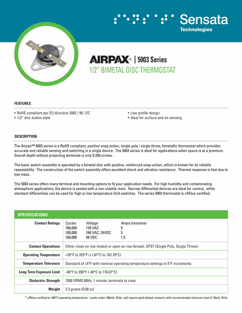
5003 Series1/2” BIMETAL DISC THERMOSTAT
• Lowprofiledesign• Idealforsurfaceandairsensing
FEATURES
• RoHScompliantperEUdirective2002/95/EC• 1/2”discbuttonstyle
DESCRIPTION
TheAirpax™5003seriesisaRoHScompliant,positivesnapaction,singlepole/singlethrow,bimetallicthermostatwhichprovidesaccurateandreliablesensingandswitchinginasingledevice.The5003seriesisidealforapplicationswhenspaceisatapremium.Overalldepthwithoutprojectingterminalsisonly0.250inches.
Thebasicswitchassemblyisoperatedbyabimetaldiscwithpositive,reinforcedsnap-action,whichisknownforitsreliablerepeatability.Theconstructionoftheswitchassemblyoffersexcellentshockandvibrationresistance.Thermalresponseisfastduetolowmass.
The5003seriesoffersmanyterminalandmountingoptionstofityourapplicationneeds.Forhighhumidityandcontaminatingatmosphereapplications,thedeviceissealedwithanon-volatileresin.Narrowdifferentialdevicesareidealforcontrol,whilestandarddifferentialscanbeusedforhighorlowtemperaturelimitswitches.Theseries5003thermostatiscЯUuscertified.
SPECIFICATIONS
Contact Ratings Cycles Voltage Amps (resistive) 100,000 120VAC 5100,000 240VAC,24VDC 3100,000 48VDC 1.5
Contact Operations Eithercloseonrise(make)oropenonrise(break),SPST(SinglePole,SingleThrow)
Operating Temperature +35°Fto325°F(+1.67°Cto162.78°C)
Temperature Tolerance Standardof±5°Fwithnominaloperatingtemperaturesettingsin5°Fincrements
Long Term Exposure Limit -40°Fto350°F(-40°Cto176.67°C)
Dielectric Strength 1500VRMS60Hz,1minute,terminalstocase
Weight 2.3grams(0.08oz)
* cЯUuscertifiedto168°Coperatingtemperature.Loadsunder100mA,5Vdc,willrequiregold-platedcontacts,withrecommendedminimumloadof10mA,5Vdc.
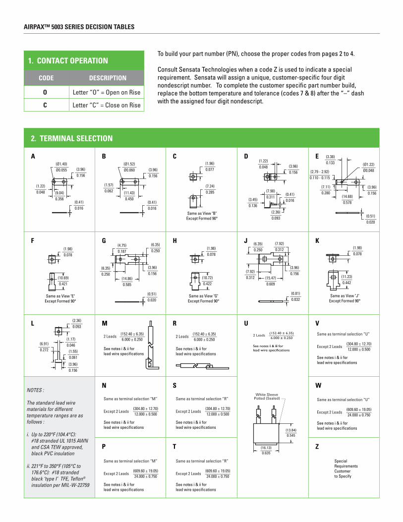
2. TERmINAL SELECTION
A B C D E
F G H J K
L m R U V
NOTES : The standard lead wire materials for different temperature ranges are as follows :
i. Up to 220°F (104.4°C): #18 stranded UL 1015 AWN and CSA TEW approved, black PVC insulation
ii. 221°F to 350°F (105°C to 176.6°C): #18 stranded black ‘type I’ TFE, Teflon®
insulation per MIL-W-22759
N S W
P T Z
0.093(2.36)
0.272(6.91) 0.046
(1.17)
0.061(1.55)
0.156(3.96)
See notes i & ii forlead wire specifications
2 Leads6.000 ± 0.250
(152.40 ± 6.35)
Same as terminal selection “M”
Except 2 Leads12.000 ± 0.500
(304.80 ± 12.70)
See notes i & ii forlead wire specifications
Same as terminal selection “M”
Except 2 Leads24.000 ± 0.750
(609.60 ± 19.05)
See notes i & ii forlead wire specifications
See notes i & ii forlead wire specifications
2 Leads6.000 ± 0.250
(152.40 ± 6.35)
Same as terminal selection “R”
Except 2 Leads12.000 ± 0.500
(304.80 ± 12.70)
See notes i & ii forlead wire specifications
Same as terminal selection “R”
Except 2 Leads24.000 ± 0.750
(609.60 ± 19.05)
See notes i & ii forlead wire specifications
0.133(3.38)
0.110 - 0.115(2.79 - 2.92)
0.280(7.11)
0.578(14.68)
0.156(3.96)
0.020(0.51)
Ø0.048(Ø1.22)
Ø0.055(Ø1.40)
0.156(3.96)
0.048(1.22)
0.356(9.04)
0.016(0.41)
Ø0.060(Ø1.52)
0.156(3.96)
0.062(1.57)
0.450(11.43)
0.016(0.41)
Same as View "B"Except Formed 90°
0.077(1.96)
0.285(7.24)
0.048(1.22)
0.311(7.90)
0.136(3.45)
0.156(3.96)
0.016(0.41)
0.093(2.36)
Same as View "E"Except Formed 90°
0.078(1.98)
0.421(10.69)
0.187(4.75)
0.250(6.35)
0.250(6.35)
0.156(3.96)
0.585(14.86)
0.020(0.51) Same as View "G"
Except Formed 90°
0.078(1.98)
0.422(10.72)
0.312(7.92)
0.250(6.35)
0.312(7.92)
0.609(15.47)
0.156(3.96)
0.032(0.81) Same as View "J"
Except Formed 90°
0.078(1.98)
0.442(11.23)
0.545(13.84)
White SleevePotted (Sealed)
0.635(16.13)
2 Leads6.000 ± 0.250
(152.40 ± 6.35)
See notes i & ii forlead wire specifications
Same as terminal selection “U”
Except 2 Leads12.000 ± 0.500
(304.80 ± 12.70)
See notes i & ii forlead wire specifications
Same as terminal selection “U”
Except 2 Leads24.000 ± 0.750
(609.60 ± 19.05)
See notes i & ii forlead wire specifications
SpecialRequirementsCustomerto Specify
1. CONTACT OPERATION
CODE DESCRIPTION
O Letter“O”=OpenonRise
C Letter“C”=CloseonRise
Tobuildyourpartnumber(PN),choosethepropercodesfrompages2to4. ConsultSensataTechnologieswhenacodeZisusedtoindicateaspecialrequirement.Sensatawillassignaunique,customer-specificfourdigitnondescriptnumber.Tocompletethecustomerspecificpartnumberbuild,replacethebottomtemperatureandtolerance(codes7&8)afterthe“–”dashwiththeassignedfourdigitnondescript.
AIRPAX™ 5003 SERIES DECISION TABLES
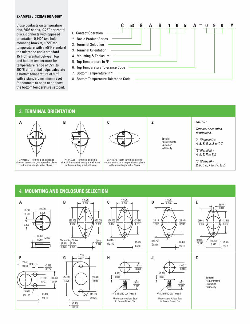
3. TERmINAL ORIENTATION
A B C Z NOTES :
Terminal orientation restrictions :
‘A’ (Opposed) = A, B, E, G, J, R to T, Z
‘B’ (Parallel) = A, B, E, R to T, Z
‘C’ (Vertical) = C, D, F, H, K to P, U to Z
OPPOSED - Terminals on oppositesides of thermostat, on a parallel plane
to the mounting bracket / base
SpecialRequirementsCustomerto Specify
PARALLEL - Terminals on sameside of thermostat, on a parallel plane
to the mounting bracket / base
VERTICAL - Both terminals extendup and away, on a perpendicular plane
to the mounting bracket / base
4. mOUNTING AND ENCLOSURE SELECTION
A B C D E
F G H J Z
0.131(3.32)
MAX0.250(6.35)
0.606(15.39)
0.300(7.61)
0.640(16.26)
0.906(23.01)
0.018(0.46)
1.187(30.15)
2 Mounting Slots
0.140(3.56)
0.172(4.37)
x
0.640(16.26)
0.937(23.80)
0.018(0.46)
1.187(30.15)
Ø0.140(Ø3.55)
0.640(16.26)
0.937(23.80)
0.018(0.46)
1.187(30.15)
Ø0.109(Ø2.76)
0.640(16.26)
0.937(23.80)
0.018(0.46)
1.166(29.62)
Ø0.140(Ø3.56)
0.140(3.56)
0.125(3.18)
0.018(0.46)Ø0.147
(Ø3.73)
0.843(21.41)
REF
0.437(11.10)
0.687(17.45)
0.018(0.46)
1.375(34.92)
1.000(25.40)
Ø0.125(Ø3.18)
0.687(17.45)
0.375(9.52)
0.406(10.31)
6-32 UNC-2A Thread
Undercut to Allow Studto Screw Down Flat
0.031(0.79)
0.375(9.52)
0.406(10.31)
8-32 UNC-2A Thread
Undercut to Allow Studto Screw Down Flat
0.031(0.79)
SpecialRequirementsCustomerto Specify
1. ContactOperation
* BasicProductSeries
C 53 1 0 5
2. TerminalSelection
G
3. TerminalOrientation
A
4. Mounting&Enclosure
B
5. TopTemperaturein°F
6. TopTemperatureToleranceCode
A 0 9 0 Y
7. BottomTemperaturein°F
8. BottomTemperatureToleranceCode
EXAmPLE : C53GAB105A-090Y Closecontactsontemperaturerise,5003series,0.25”horizontalquick-connectswithopposedorientation,0.140”twoholemountingbracket,105°Ftoptemperaturewitha±5°Fstandardtoptoleranceandastandard15°Fdifferentialbetweentopandbottomtemperaturefortemperaturerangeof35°Fto200°F,differentialhelpscalculateabottomtemperatureof90°Fwithastandardminimumresetforcontactstoopenatorabovethebottomtemperaturesetpoint.

SENSATATECHNOLOGIES 529PleasantStreetAttleboro,MA02703-0964USA 1-508-236-3287(Main) 1-508-236-1598(Fax) http://airpax.sensata.com http://www.sensata.com
ImportantNotice:SensataTechnologies(Sensata)reservestherighttomakechangestoordiscontinueanyproductorserviceidentifiedinthispublicationwithoutnotice.Sensataadvises its customers to obtain the latest version of therelevant information to verify, before placing any orders,that the information being relied upon is current. Sensataassumes no responsibility for infringement of patents orrights of others based on Sensata applications assistanceor product specifications since Sensata does not possessfullaccessconcerningtheuseorapplicationofcustomers’products. Sensata also assumes no responsibility forcustomers’productdesigns.
245–500–6010 Printed In U.S.A., August, 2009
5. TOP TEmPERATURE IN °F
°F °C °F °C °F °C
Temperature Setting 35°Fto200°F 1.6°Cto93°C 201°Fto300°F 94°Cto149°C 301°Fto325°F 150°Cto163°C
Standard Tolerance ±5°F ±2.8°C ±8°F ±4.4°C ±10°F ±5.6°C
Nominal Differential 15°F 8.3°C 25°F 13.8°C 30°F 16.7°C
NOTES: · Select any temperature in the range of 35°F to 325°F. Standard choices fall on the 5°F increments, for example 35°F, 40°F, 45°F, 50°F... up to 320°F or 325°F · Specify the °F temperature in the part numbering scheme as a three digit code without the ‘°F’ in the part number. For example, for 90°F, put in code ‘090’
6. TOP TEmPERATURE TOLERANCE
CODE A B C X Z
± °F ±5°F ±8°F ±10°F Maximum CustomertoSpecify
± °C ±2.8°C ±4.4°C ±5.6°C Maximum CustomertoSpecify
NOTES: · The standard tolerance for the top temperature is based on the temperature range the top temperature falls in, please refer to “5. Top Temperature in °F” chart, and select the appropriate code for a standard top temperature tolerance.
7. BOTTOm TEmPERATURE IN °F
“BottomTemperaturein°F”equalsthe“TopTemperaturein°F”minusthe“NominalDifferentialin°Fforthattemperature”.
Example1:50°F–15°F=35°FExample2:250°F–25°F=225°FExample3:310°F–30°F=280°F
NOTES: · Specify the °F temperature in the part numbering scheme as a three digit code without the ‘°F’ in the part number (example 90°F, put in the code as ‘090’)
8. BOTTOm TEmPERATURE TOLERANCE
CODE A B C Y Z
± °F ±5°F ±8°F ±10°F Minimum CustomertoSpecify
± °C ±2.8°C ±4.4°C ±5.6°C Minimum CustomertoSpecify
NOTES: · The typical standard bottom temperature tolerance is a ‘Y’ = minimum trip, which indicates the “reset” trip occurs at or above the lower temperature set point. · The other standard tolerances are based on the temperature range the bottom temperature is in. The most convenient solution is to use either the ‘Y’ minimum reset code or choose the same tolerance code selection used in “6. Top Temperature Tolerance Code”.