50140581 001 auftrags-nr.: page 1 of 31
TRANSCRIPT

TUV Rheinland (Guangdong) Ltd. No.199 Kezhu Road, Guangzhou Science City, Guangzhou 510663, Guangdong Province, P.R. China
Produkte Products
Prüfbericht-Nr.: Test Report No.: 50140581 001
Auftrags-Nr.: Order No.:
174072846 Seite 1 von 31 Page 1 of 31
Kunden-Referenz-Nr.: Client Reference No.:
342925 Auftragsdatum: Order date.:
27 Sep, 2017
Auftraggeber: Client:
Foshan Electrical And Lighting Co., Ltd. 64 North Fenjiang Road, Foshan, Guangdong 528000, P. R. China
Prüfgegenstand: Test item:
LED BULB
Bezeichnung / Typ-Nr.: Identification / Type No.:
G9-2.2-XX/G19/54, G9-2-XX/G19/54
(refer to section 3 for detailed variable XX)
Auftrags-Inhalt: Order content:
TUV Rheinland – EMC Service
Prüfgrundlage: Test specification:
EN 55015:2013 EN 55015:2013+A1 EN 61547:2009 EN 61000-3-2:2014 EN 61000-3-3:2013
Wareneingangsdatum: Date of receipt:
11 Dec, 2017
Prüfmuster-Nr.: Test sample No.:
174072846-001
Prüfzeitraum: Testing period:
Refer to test report
Ort der Prüfung: Place of testing:
Refer to section 2.1
Prüflaboratorium: Testing laboratory:
TÜV Rheinland (Guangdong) Ltd.
Prüfergebnis*: Test result*:
Pass
geprüft von / tested by:
02 May, 2018 Amy Wang/PM
kontrolliert von / reviewed by:
03 May, 2018 Jeffery Xie/TC
Datum Date
Name/Stellung Name/Position
Unterschrift Signature
Datum Date
Name/Stellung Name/Position
Unterschrift Signature
Sonstiges/ Other:
Zustand des PrüfgegenstandesbeiAnlieferung: Condition of the test item at delivery:
Prüfmuster vollständig und unbeschädigt Test item complete and undamaged
* Legende: 1 = sehr gut 2 = gut 3 = befriedigend 4 = ausreichend 5 = mangelhalt P(ass) = entspricht o.g. Prüfgrundlage(n) F(ail) = entspricht nicht o.g. Prüfgrundlage(n) N/A = nicht anwendbar N/T = nichtgetestet
Legend: 1 = very good 2 = good 3 = satisfactory 4 = sufficient 5 = poor P(ass) = passed a.m. test specifications(s) F(ail) = failed a.m. test specifications(s) N/A = not applicable N/T = not tested
Dieser Prüfbericht bezieht sich nur auf das o.g. Prüfmuster und darf ohne Genehmigung der Prüfstelle nicht auszugsweise vervielfältigt werden. Dieser Bericht berechtigt nicht zur Verwendung eines Prüfzeichens.
This test report only relates to the a. m. test sample. Without permission of the test center this test report is not permitted to be duplicated in extracts. This test report does not entitle to carry any test mark.

Produkte
Products
Prüfbericht - Nr.:
Test Report No. 50140581 001 Seite 2 von 31
Page 2 of 31
TEST SUMMARY
5.1.1 HARMONICS CURRENT EMISSION ON AC MAINS
RESULT: Pass
5.1.2 VOLTAGE CHANGES, VOLTAGE FLUCTUATIONS AND FLICKER
RESULT: Pass
5.1.3 TERMINAL CONTINUOUS DISTURBANCE VOLTAGE
RESULT: Pass
5.1.4 RADIATED ELECTROMAGNETIC DISTURBANCES
RESULT: Pass
5.2.1 RADIATED DISTURBANCE (30 MHZ – 300 MHZ, CDN METHOD)
RESULT: Pass
6.2.1 POWER-FREQUENCY MAGNETIC FIELDS
RESULT: N/A
6.2.2 RADIO-FREQUENCY COMMON MODE / CONDUCTED SUSCEPTIBILITY (CS)
RESULT: Pass
6.2.3 RADIO-FREQUENCY ELECTROMAGNETIC FIELDS (RS)
RESULT: Pass
6.3.1 ELECTRICAL FAST TRANSIENTS (EFT)
RESULT: Pass
6.3.2 SURGE
RESULT: Pass
6.3.3 ELECTROSTATIC DISCHARGES (ESD)
RESULT: Pass
6.4.1 VOLTAGE DIPS AND INTERRUPTIONS
RESULT: Pass

Produkte
Products
Prüfbericht - Nr.:
Test Report No. 50140581 001 Seite 3 von 31
Page 3 of 31
Contents
1. GENERAL REMARKS ........................................................................................................... 5
1.1 COMPLEMENTARY MATERIALS ........................................................................................... 5
2. TEST SITES .......................................................................................................................... 5
2.1 TEST FACILITIES .................................................................................................................. 5
2.2 LIST OF TEST AND MEASUREMENT INSTRUMENTS ............................................................. 5
3. GENERAL PRODUCT INFORMATION .................................................................................... 6
3.1 PRODUCT FUNCTION AND INTENDED USE .......................................................................... 6
3.2 RATINGS AND SYSTEM DETAILS ......................................................................................... 6
3.3 INDEPENDENT OPERATION MODES ..................................................................................... 7
3.4 NOISE GENERATING AND NOISE SUPPRESSING PARTS .................................................... 7
3.5 SUBMITTED DOCUMENTS .................................................................................................... 7
4. TEST SET-UP AND OPERATION MODES .............................................................................. 8
4.1 PRINCIPLE OF CONFIGURATION SELECTION....................................................................... 8
4.2 PHYSICAL CONFIGURATION FOR TESTING.......................................................................... 8
4.3 TEST OPERATION AND TEST SOFTWARE ........................................................................... 8
4.4 SPECIAL ACCESSORIES AND AUXILIARY EQUIPMENT ........................................................ 8
4.5 COUNTERMEASURES TO ACHIEVE EMC COMPLIANCE ...................................................... 8
5. TEST RESULTS E M I S S I O N ........................................................................................ 9
5.1 EMISSION IN THE FREQUENCY RANGE UP TO 30 MHZ ....................................................... 9
5.1.1 Harmonics Current Emission on AC Mains ......................................................................................... 9
5.1.2 Voltage Changes, Voltage Fluctuations and Flicker ........................................................................ 10
5.1.3 Terminal Continuous Disturbance Voltage ........................................................................................ 11
5.1.4 Radiated Electromagnetic Disturbances ............................................................................................ 13
5.2 EMISSION IN THE FREQUENCY RANGE ABOVE 30 MHZ ................................................... 15
5.2.1 Radiated Disturbance (30 MHz – 300 MHz, CDN method) ............................................................ 15
6 . TEST RESULTS I M M U N I T Y ..................................................................................... 17
6.1 CLASSIFICATION OF APPARATUS ..................................................................................... 17
6.2 CONTINUOUS DISTURBANCES .......................................................................................... 18
6.2.1 Power-frequency Magnetic Fields ....................................................................................................... 18
6.2.2 Radio-frequency Common Mode / Conducted Susceptibility (CS) ................................................ 19

Produkte
Products
Prüfbericht - Nr.:
Test Report No. 50140581 001 Seite 4 von 31
Page 4 of 31
6.2.3 Radio-frequency Electromagnetic Fields (RS) .................................................................................. 21
6.3 TRANSIENT DISTURBANCES .............................................................................................. 23
6.3.1 Electrical Fast Transients (EFT) .......................................................................................................... 23
6.3.2 Surge ....................................................................................................................................................... 25
6.3.3 Electrostatic Discharges (ESD) ........................................................................................................... 27
6.4 POWER SUPPLY ALTERATIONS ........................................................................................ 29
6.4.1 Voltage Dips and Interruptions ............................................................................................................ 29
7. LIST OF TABLES ................................................................................................................ 31
8. LIST OF PHOTOGRAPHS .................................................................................................... 31

Produkte
Products
Prüfbericht - Nr.:
Test Report No. 50140581 001 Seite 5 von 31
Page 5 of 31
1. General Remarks
When applying the basic standards in this test report, please refer to the applied generic or
product family standards for edition information:
For dated basic standards, only the edition cited applies. For undated basic standards, the
latest edition (including any amendments) applies.
1.1 Complementary Materials
All attachments are integral parts of this test report. This applies especially to the following
appendix:
Appendix 1: Test result.
Appendix 2: List of Test and Measurement Equipment.
2. Test Sites
2.1 Test Facilities
1) WALTEK SERVICES (FO SHAN) CO., LTD.
No.13-19,2/F, 2nd Building, Sunlink International Machinery City, Chencun Town,
Shunde District, Foshan528313, Guangdong, China
Test items: Others
2) WALTEK SERVICES (NING BO) CO., LTD.
1F,No.6 Building,No.1177 Lingyun Road,Ningbo National Hi-Tech Zone,Ningbo,Zhejiang
Province,315040, China
Test items: RS
The test at these test sites has been conducted under the supervision of a TÜV
Rheinland engineer.
2.2 List of Test and Measurement Instruments
Table 1: List of Test and Measurement Equipment
Refer to attached Appendix 2.

Produkte
Products
Prüfbericht - Nr.:
Test Report No. 50140581 001 Seite 6 von 31
Page 6 of 31
3. General Product Information
The following submitted samples are general light source of LED module with integral LED
driver and lamp cap for indoor used only.
All models have the same circuit diagram, PCB layout except the rated power and LED
model name are different.
Item Model Rated input Rated current
(A)
Rated Power
(W)
LED model name
LED quantity
(pcs)
Lamp cap
1 G9-2.2-XX/G19/54 AC220-240V~
50/60Hz
0,01 2,2 3528 Series 14 G9
2 G9-2-XX/G19/54 0,01 2 M-SP3528WXS-460R-R70/R80
14 G9
Remark: XX is two numbers 27-65, stand for colour temperature 2700-6500K.
Based on above information, full EMC tests were performed on models G9-2.2-XX/G19/54.
For details please refer to the Technical Documentation.
3.1 Product Function and Intended Use
Refer to Technical Documentation.
3.2 Ratings and System Details
Type designation: Refer to section 3
Rated power: Refer to section 3
Input voltage: Refer to section 3
For details please refer to the Technical Documentation.

Produkte
Products
Prüfbericht - Nr.:
Test Report No. 50140581 001 Seite 7 von 31
Page 7 of 31
3.3 Independent Operation Modes
The basic operation modes are:
A: On.
B: Off.
Refer to the Technical Documentation for further information.
3.4 Noise Generating and Noise Suppressing Parts
Refer to the Technical Documentation for further information.
3.5 Submitted Documents
Construction Drawing
Circuit Diagram
Difference Declaration
PCB Layout
Component List
Rating Label
User Manual

Produkte
Products
Prüfbericht - Nr.:
Test Report No. 50140581 001 Seite 8 von 31
Page 8 of 31
4. Test Set-up and Operation Modes
4.1 Principle of Configuration Selection
Emission: The equipment under test (EUT) was configured to measure its highest
possible radiation level. The test modes were adapted accordingly in reference to the
instructions for use.
Immunity: The equipment under test (EUT) was configured to have its highest possible
susceptibility against the tested phenomena. The test modes were adapted accordingly in
reference to the instructions for use.
4.2 Physical Configuration for Testing
Refer to relative paragraphs of this test report.
4.3 Test Operation and Test Software
Refer to test setup in chapter 5 and chapter 6.
4.4 Special Accessories and Auxiliary Equipment
None.
4.5 Countermeasures to achieve EMC Compliance
No additional countermeasures to the submitted test sample(s) were employed to achieve
compliance.

Produkte
Products
Prüfbericht - Nr.:
Test Report No. 50140581 001 Seite 9 von 31
Page 9 of 31
5. Test Results E M I S S I O N
5.1 Emission in the Frequency Range up to 30 MHz
5.1.1 Harmonics Current Emission on AC Mains
RESULT: Pass
Test Specification
Basic standard : EN 61000-3-2:2014
Measurement equipment requirement : IEC 61000-4-7
Measured harmonics : 1 – 40
Equipment class : C
Limits : Clause 7.3
There is no limit described in EN 61000-3-2:2014 for class C equipment below or equal to
25W other than discharge lighting equipment, so this test is not applicable for these
models.

Produkte
Products
Prüfbericht - Nr.:
Test Report No. 50140581 001 Seite 10 von 31
Page 10 of 31
5.1.2 Voltage Changes, Voltage Fluctuations and Flicker
RESULT: Pass
Test Specification
Basic standard : EN 61000-3-3:2013
Measurement equipment requirement : IEC 61000-4-15
Limits : EN 61000-3-3:2013, Clause 5
According to EN 61000-3-3:2013, clause A.2* the voltage fluctuation and flicker on AC
Mains were not measured.
* EN 61000-3-3:2013,clause A.2:
“Pst and Plt evaluations are required only for lighting equipment which is likely to produce
flicker; for example: disco lighting and automatically regulated equipment.”
“Incandescent lamp luminaires with ratings less than or equal to 1000 W and discharge
lamp luminaires with ratings less than or equal to 600 W and LED luminaires with ratings
less than or equal to 200W, are deemed to comply with the dmax limits in this standard
and are not required to be tested.”

Produkte
Products
Prüfbericht - Nr.:
Test Report No. 50140581 001 Seite 11 von 31
Page 11 of 31
5.1.3 Terminal Continuous Disturbance Voltage
RESULT: Pass
Test Specification
Test procedure : EN 55015:2013+A1,EN 55015:2013
Port : AC Mains
Frequency range of Mains : 9kHz-30MHz
Test site : Shielded Room
Limits : EN 55015:2013+A1,
EN 55015:2013, Clause 4.3.1,Table 2a
Test Setup
Date of testing : Refer to the Appendix 1
Input voltage : Refer to the Appendix 1
Operation mode : On
Artificial hand : N/A
Test configuration : Table-top
Temperature : Refer to the Appendix 1
Humidity : Refer to the Appendix 1
Air pressure : Refer to the Appendix 1

Produkte
Products
Prüfbericht - Nr.:
Test Report No. 50140581 001 Seite 12 von 31
Page 12 of 31
Photograph 1: Set-up for Continuous Disturbance Voltage
Test Result
Measurement uncertainty:2.66dB (k=2, σ= 95%)
If the result of the measurement with the Quasi Peak detector is below the Average limit,
the measurement with Average Detector has been omitted.
Disturbances other than those mentioned are small or not detectable.
For test results, please refer to the attached Appendix 1.

Produkte
Products
Prüfbericht - Nr.:
Test Report No. 50140581 001 Seite 13 von 31
Page 13 of 31
5.1.4 Radiated Electromagnetic Disturbances
RESULT: Pass
Test Specification
Test procedure : EN 55015:2013+A1,
EN 55015:2013, Clause 9
Port : Enclosure
Frequency range : 9kHz-30MHz
Test site : Shielded Room
Limits : EN 55015:2013+A1,
EN 55015:2013, Clause 4.4, Table 3a
Test Setup
Date of testing : Refer to the Appendix 1
Input voltage : Refer to the Appendix 1
Operation mode : On
Temperature : Refer to the Appendix 1
Humidity : Refer to the Appendix 1
Air pressure : Refer to the Appendix 1

Produkte
Products
Prüfbericht - Nr.:
Test Report No. 50140581 001 Seite 14 von 31
Page 14 of 31
Photograph 2: Set-up for Radiated Electromagnetic Disturbances
Test Result
Measurement uncertainty:3.00dB (k=2, σ= 95%)
Refer to the attached Appendix 1

Produkte
Products
Prüfbericht - Nr.:
Test Report No. 50140581 001 Seite 15 von 31
Page 15 of 31
5.2 Emission in the Frequency Range above 30 MHz
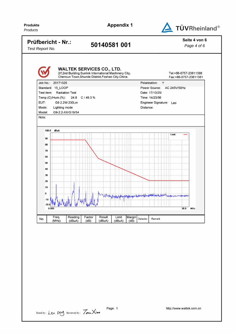
5.2.1 Radiated Disturbance (30 MHz – 300 MHz, CDN method)
RESULT: Pass
Test Specification
Family standard : EN 55015:2013, EN 55015:2013+A1
Port : AC mains
Frequency range : 30MHz -300MHz
Test site : Shielded Room
Limits : B.6, Table B.1
Test Setup
Date of testing : Refer to the Appendix 1
Input voltage : Refer to the Appendix 1
Operation mode : On
Temperature : Refer to the Appendix 1
Humidity : Refer to the Appendix 1
Air pressure : Refer to the Appendix 1

Produkte
Products
Prüfbericht - Nr.:
Test Report No. 50140581 001 Seite 16 von 31
Page 16 of 31
Photograph 3: Set-up for Radiated Disturbance (CDN method)
Test Result
Measurement uncertainty: 3.21dB (k=2, σ= 95%)
Disturbances other than those mentioned are small or not detectable.
Refer to the attached Appendix 1.

Produkte
Products
Prüfbericht - Nr.:
Test Report No. 50140581 001 Seite 17 von 31
Page 17 of 31
6 . Test Results I M M U N I T Y
6.1 Classification of Apparatus
According to EN 61547:2009, the appliance shall fulfill the requirements of:
Continuous Disturbances
Power-frequency magnetic field Criterion A
Radio-Frequency Common Mode / Conducted Susceptibility (CS) Criterion A
Radio-frequency Electromagnetic Fields (RS) Criterion A
Transient Disturbances
Electrical Fast Transients (EFT) Criterion B
Surge Criterion C
Electrostatic Discharges (ESD) Criterion B
Power Supply Alterations
Voltage Dips and Interruptions Criterion B + C

Produkte
Products
Prüfbericht - Nr.:
Test Report No. 50140581 001 Seite 18 von 31
Page 18 of 31
6.2 Continuous Disturbances
6.2.1 Power-frequency Magnetic Fields
RESULT: N/A
Test Specification
Family Standard : EN 61547:2009
Basic standard : IEC 61000-4-8
Test Level (A/m) : 3A/m
Frequency : 50Hz and 60Hz
Performance criterion : A
The immunity against power frequency magnetic field was not tested because the EUT
does not contain components, which are susceptible to magnetic fields.According to
EN 61547:2009, clause 5.4: “these tests … need only to be applied to equipment
containing components susceptible to magnetic fields.”

Produkte
Products
Prüfbericht - Nr.:
Test Report No. 50140581 001 Seite 19 von 31
Page 19 of 31
6.2.2 Radio-frequency Common Mode / Conducted Susceptibility (CS)
RESULT: Pass
Test Specification
Family standard : EN 61547:2009
Basic standard : IEC 61000-4-6
Characteristics of the test generator :
Output impedance : 50 Ω Harmonics and distortion : Any spurious spectral line at least 15 dB
below the carrier level Direct injection device 100 Ω impedance
Frequency bandwidth : 150 kHz to 80MHz
Frequency step : 1% with 1 s dwell time
Performance criterion : A
Test Setup
Date of testing : 12 Dec, 2017
Input voltage : AC 230V, 50Hz
Operation mode : On mode
Artificial hand : N/A
Signal lines and control lines : N/A
Output dc power ports : N/A
Input ac power ports : 3V (rms)
Temperature : 23.4°C
Humidity : 52.1%
Air pressure : 101.2kPa

Produkte
Products
Prüfbericht - Nr.:
Test Report No. 50140581 001 Seite 20 von 31
Page 20 of 31
Photograph 4: Set-up for Radio-frequency Common Mode / Conducted
Susceptibility (CS)
Test Result
Table 2: Immunity against Radio-frequency Common Mode / Conducted
Susceptibility (CS)
Coupling point Application Level (V(r.m.s)) Remark
Power ports
AC input port CDN-M2 3 Applied, *)
DC output port EM clamp 3 N/A
Signal and control lines
Current Clamp 3 N/A
EM clamp 3 N/A
*) Remark: No degradation was found.

Produkte
Products
Prüfbericht - Nr.:
Test Report No. 50140581 001 Seite 21 von 31
Page 21 of 31
6.2.3 Radio-frequency Electromagnetic Fields (RS)
RESULT: Pass
Test Specification
Family standard : EN 61547:2009
Basic standard : IEC 61000-4-3
Test site : FAC
Uniform field area (UFA) : 1.5 m x 1.5 m, 16 points with a minimum
UFA size 0.5 m x 0.5 m,75 % of calibration
points within specifications if UFA is larger
than 0.5 m x 0.5 m . 100 % (all 4 points) in
the specifications for 0.5 x 0.5 m UFA
Amplitude modulation : 80 % ± 5 % in depth, 1 kHz ± 10 % sine wave
Frequency bandwidth : 80MHz to 1000MHz
Level : 3 V/ m(un-modulated)
Frequency step : 1% with 1 s dwell time
Performance criterion : A
Test Setup
Date of testing : 22 Dec, 2017
Input voltage : AC 230V, 50Hz
Operation mode : On mode
Artificial hand : N/A
Temperature : 21.0°C
Humidity : 44.5%
Air pressure : 100.8kPa

Produkte
Products
Prüfbericht - Nr.:
Test Report No. 50140581 001 Seite 22 von 31
Page 22 of 31
Photograph 5: Set-up for Radio-frequency Electromagnetic Fields (RS)
Test Result
Table 3: Immunity against Radio-frequency Electromagnetic Fields (RS)
Side of the equipment under test
Frequency (MHz) Antenna polarization (Vertical/Horizontal)
Remark
Front 80-1000 V and H Applied, *)
Rear 80-1000 V and H Applied, *)
Right 80-1000 V and H Applied, *)
Left 80-1000 V and H Applied, *)
*) Remark: No degradation was found.

Produkte
Products
Prüfbericht - Nr.:
Test Report No. 50140581 001 Seite 23 von 31
Page 23 of 31
6.3 Transient Disturbances
6.3.1 Electrical Fast Transients (EFT)
RESULT: Pass
Test Specification
Family standard : EN 61547:2009
Basic standard : IEC 61000-4-4
Wave shape of the pulse in 50 Ω load :
Rise time 5 ns ± 30 % Duration 50 ns ± 30 %
Wave shape into 1 kΩ load :
Rise time 5 ns ± 30 % Duration 50 ns with a tolerance of -15 ns to+100 ns
Burst duration : 15 ms ± 20 % at 5 kHz
Burst period : 300 ms ± 20 %
Repetition frequency : 5 kHz
Polarity : Positive and negative
Time of application : 2 minutes
Performance criterion : B
Test Setup
Date of testing : 11 Dec, 2017
Input voltage : AC 230V, 50Hz
Operation mode : On mode
Artificial hand : N/A
Signal and telecommunication ports : N/A
Output dc power ports : N/A
Input ac power ports : 1kV
Temperature : 23.6°C
Humidity : 52.4%
Air pressure : 101.1kPa

Produkte
Products
Prüfbericht - Nr.:
Test Report No. 50140581 001 Seite 24 von 31
Page 24 of 31
Photograph 6: Set-up for Electrical Fast Transient (EFT)
Test Result
Table 4: Immunity against Electrical Fast Transients (EFT)
Coupling point Application Level (kV) Polarity Remark
Power ports
AC power port Coupling network
1 + Applied, *)
1 - Applied, *)
DC power port Coupling clamp 0.5 + N/A
0.5 - N/A
*) Remark: No degradation was found.

Produkte
Products
Prüfbericht - Nr.:
Test Report No. 50140581 001 Seite 25 von 31
Page 25 of 31
6.3.2 Surge
RESULT: Pass
Test Specification
Family standard : EN 61547:2009
Basic standard : IEC 61000-4-5
Definitions of the waveform parameters :
Front time 1.2 µs ± 30 % Time to half value 50 µs ± 20 %
Source impedance :
Power line symmetrical
Power line unsymmetrical
2 Ω + 18 µF
12 Ω + 9 µF
Polarity : Positive and negative
Number of surges / polarity /phase angle : 5
Phase angles : 90°and 270 °
Repetition rate : 60 s
Performance criterion : C
Test Setup
Date of testing : 11 Dec, 2017
Input voltage : AC 230V, 50Hz
Operation mode : On mode
Temperature : 23.4°C
Humidity : 52.6%
Air pressure : 101.2kPa

Produkte
Products
Prüfbericht - Nr.:
Test Report No. 50140581 001 Seite 26 von 31
Page 26 of 31
Photograph 7: Set-up for Surge
Test Result
Table 5: Surge Immunity Tests
Coupling point Application Level (kV) Polarity Remark
AC power port
Between phase and neutral 0.5 + Applied, *)
0.5 - Applied, *)
AC power port Between phase and earth 0.5,1,2 + N/A
0.5,1,2 - N/A
AC power port Between neutral and earth 0.5,1,2 + N/A
0.5,1,2 - N/A
*) Remark: No degradation was found.

Produkte
Products
Prüfbericht - Nr.:
Test Report No. 50140581 001 Seite 27 von 31
Page 27 of 31
6.3.3 Electrostatic Discharges (ESD)
RESULT: Pass
Test Specification
Family standard : EN 61547:2009
Basic standard : IEC 61000-4-2
Discharge impedance : 330 Ω / 150 pF
Number of discharges : ≥ 10
Polarity : Positive and negative
Discharge location : See photo documentation of the test set-up
All external locations accessible by hand
Horizontal coupling plate (HCP)
Vertical coupling plate (VCP)
Performance criterion : B
Test Setup
Date of testing : 11 Dec, 2017
Input voltage : AC 230V, 50Hz
Operation mode : On mode
Temperature : 23.4°C
Humidity : 52.1%
Air pressure : 101.2kPa

Produkte
Products
Prüfbericht - Nr.:
Test Report No. 50140581 001 Seite 28 von 31
Page 28 of 31
Photograph 8: Set-up for Electrostatic Discharge
Contact Discharge ±4kV Air Discharge ±2,4,8kV
Test Result
Table 6: Electrostatic Discharge
Direct discharges
Air discharges Discharge location
Air discharge voltage (kV)
Polarity Remark
Refer to Photograph of ESD setup 2, 4, 8 + Applied, *)
Refer to Photograph of ESD setup 2, 4, 8 - Applied, *)
Non-conductive parts of enclosure 2, 4, 8 +/- Applied, *)
Contact discharges Discharge location
Contact discharge voltage (kV)
Polarity Remark
Refer to Photograph of ESD setup 4 + N/A
Refer to Photograph of ESD setup 4 - N/A
Conductive parts 4 +/- Applied, *)
Indirect discharges
Contact discharges Discharge location
Contact discharge voltage (kV)
Polarity Remark
HCP 4 +/- Applied, *)
VCP 4 +/- Applied, *)
*) Remark: No degradation was found.
Produkte
Products
Prüfbericht - Nr.:
Test Report No. 50140581 001 Seite 29 von 31
Page 29 of 31
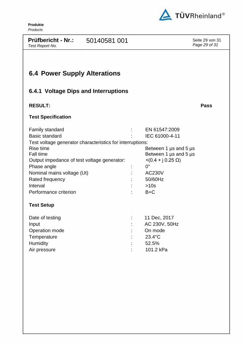
6.4 Power Supply Alterations
6.4.1 Voltage Dips and Interruptions
RESULT: Pass
Test Specification
Family standard : EN 61547:2009
Basic standard : IEC 61000-4-11
Test voltage generator characteristics for interruptions:
Rise time Between 1 µs and 5 µs Fall time Between 1 µs and 5 µs
Output impedance of test voltage generator: <(0.4 + j 0.25 Ω)
Phase angle : 0°
Nominal mains voltage (Ut) : AC230V
Rated frequency : 50/60Hz
Interval : >10s
Performance criterion : B+C
Test Setup
Date of testing : 11 Dec, 2017
Input : AC 230V, 50Hz
Operation mode : On mode
Temperature : 23.4°C
Humidity : 52.5%
Air pressure : 101.2 kPa

Produkte
Products
Prüfbericht - Nr.:
Test Report No. 50140581 001 Seite 30 von 31
Page 30 of 31
Photograph 9: Set-up for Voltage Dips and Interruptions
Test Result
Table 7: Voltage Dip and Interruptions Immunity
Interruptions
Test level (% Ut)
Duration (cycle)
Number of interruptions
Result
0 0.5 3 Applied, *)
Voltage dips
Test level (% Ut)
Duration (cycle)
Number of voltage dips
Result
70 10 3 Applied, *)
*) Remark: No degradation was found.

Produkte
Products
Prüfbericht - Nr.:
Test Report No. 50140581 001 Seite 31 von 31
Page 31 of 31
7. List of Tables
Table 1: List of Test and Measurement Equipment .............................................................................................. 5
Table 2: Immunity against Radio-frequency Common Mode / Conducted Susceptibility (CS) ..................... 20
Table 3: Immunity against Radio-frequency Electromagnetic Fields (RS) ...................................................... 22
Table 4: Immunity against Electrical Fast Transients (EFT) .............................................................................. 24
Table 5: Surge Immunity Tests .............................................................................................................................. 26
Table 6: Electrostatic Discharge ............................................................................................................................ 28
Table 7: Voltage Dip and Interruptions Immunity ................................................................................................ 30
8. List of Photographs
Photograph 1: Set-up for Continuous Disturbance Voltage ............................................................................... 12
Photograph 2: Set-up for Radiated Electromagnetic Disturbances .................................................................. 14
Photograph 3: Set-up for Radiated Disturbance (CDN method) ....................................................................... 16
Photograph 4: Set-up for Radio-frequency Common Mode / Conducted Susceptibility (CS) ....................... 20
Photograph 5: Set-up for Radio-frequency Electromagnetic Fields (RS) ........................................................ 22
Photograph 6: Set-up for Electrical Fast Transient (EFT) .................................................................................. 24
Photograph 7: Set-up for Surge ............................................................................................................................. 26
Photograph 8: Set-up for Electrostatic Discharge ............................................................................................... 28
Photograph 9: Set-up for Voltage Dips and Interruptions ................................................................................... 30

Produkte Products
Appendix 1
Prüfbericht - Nr.:
Test Report No. 50140581 001 Seite 1 von 6
Page 1 of 6

Produkte Products
Appendix 1
Prüfbericht - Nr.:
Test Report No. 50140581 001 Seite 2 von 6
Page 2 of 6

Produkte Products
Appendix 1
Prüfbericht - Nr.:
Test Report No. 50140581 001 Seite 3 von 6
Page 3 of 6
Produkte Products
Appendix 1
Prüfbericht - Nr.:
Test Report No. 50140581 001 Seite 4 von 6
Page 4 of 6

Produkte Products
Appendix 1
Prüfbericht - Nr.:
Test Report No. 50140581 001 Seite 5 von 6
Page 5 of 6

Produkte Products
Appendix 1
Prüfbericht - Nr.:
Test Report No. 50140581 001 Seite 6 von 6
Page 6 of 6

Produkte Products
Appendix 2
Prüfbericht - Nr.:
Test Report No. 50140581 001 Seite 1 von 2
Page 1 of 2
Test Equipment Model Manufacturer Serial No. Cal Until
WALTEK SERVICES (FO SHAN) CO., LTD. Disturbance Voltage
EMI Test Receiver ESCI R&S 101178 04.Jan.2019
LISN ENV216 R&S 101215 04.Jan.2019
Cable CBL2-NN-3M HUBER+SUHNER 2230300 04.Jan.2019
Switch RSU/M2 ESE --- 04.Jan.2019
Radiated electromagnetic disturbance(9kHz to 30MHz)
EMI Test Receiver ESCI R&S 101178 04.Jan.2019
Three Loops Antenna HXYZ9170 SCHWARZBECK 213 04.Jan.2019
CDN method for Lighting Equipments’ Radiated Disturbance
EMI Test Receiver ESRI R&S 101178 04.Jan.2019
CDN M016 TESEQ 31586 04.Jan.2019
Cable CBL2-NN-3M HUBER+SUHNER 2230300 04.Jan.2019
Electrostatic Discharge(ESD)
ESD Simulator NSG437 TESEQ 521 04.Jan.2019
Electrical Fast Transient(EFT)
EMS test system NSG3040 TESEQ 0319 04.Jan.2019
Step Transformer INA6501 TESEQ 206 04.Jan.2019
Surge
Surge Simulator NSG3060 TESEQ 1395 04.Jan.2019
Conducted Susceptibility (150kHz-230MHz)/(150kHz-80MHz)
Conducted Immunitytest system
NSG4070-75 TESEQ 31469 04.Jan.2019

Produkte Products
Appendix 2
Prüfbericht - Nr.:
Test Report No. 50140581 001 Seite 2 von 2
Page 2 of 2
Test Equipment Model Manufacturer Serial No. Cal Until
CDN M016 TESEQ 31586 04.Jan.2019
Voltage Dips and Interruptions
EMS test system NSG3040 TESEQ 0319 04.Jan.2019
Step Transformer INA6501 TESEQ 206 04.Jan.2019
WALTEK SERVICES (NINGBO) CO., LTD.
Radiated Susceptibility
RF Power Amplifier 5225F OPHIR 1051/1712 11.May.2019
RF Power Amplifier 5293F OPHIR 1051/171. 11.May.2019
Stacked double logarithmic periodic antenna
STLP9128E-SPECIAL
SCHWARZBECK STLP 9128E 04.May.2019
Stacked double logarithmic periodic antenna
STLP 9149 SCHWARZBECK STLP 9149 #476
04.May.2019
RF signal generator N5181A Agilent MY48080720 04.Jan.2019
Power meter NRP6A RS 101133 11.May.2019
Power meter NRP6A RS 101134 11.May.2019
Electric field probe EP 601 Narda S.T.S/PMM
--- ---