502-11/20 indexing drives - force control industries, inc
TRANSCRIPT
502-11/20-001-01
SERVICE MANUALAND
REPAIR PARTSFOR
Sizes #11, #20  PLANETARYPosidyne® INDEXINGClutch/Brake DRIVES
FORCE CONTROL INDUSTRIES, Inc.
WARNING - Read this manual before anyinstallation, maintenance and operation.
MANUFACTURERS OF MECHANICAL ANDELECTRICAL POWER TRANSMISSION EQUIPMENT

TABLE OF CONTENTSSection 1 - DESCRIPTION and OPERATION1-1 Theory of Operation .......................................... 11-2 Typical Applications .......................................... 11-3 Components in a Typical system ...................... 2
Section 2 - SPECIFICATIONS2-1 Specifications ................................................... 4
Section 3 - INSTALLATION3-1 Receiving the Drive ........................................... 53-2 Mounting the Drive ........................................... 53-3 Mounting #20 Posidyne with Planetary Gear Reducer ............................................................ 53-4 Flywheel Installation .......................................... 53-5 Installing Mounting Dowel Pins ......................... 63-6 Installing External Cooling System ................... 63-7 Installing Pneumatic System ............................ 63-8 Installing the CLPC Positioning Control ........... 7
Section 4 - LUBRICATION4-1 Checking the Oil Level ...................................... 74-2 Changing the Oil ............................................... 74-3 Type of Oil ......................................................... 8
Section 5 - OPERATIONAL CHECKS5-1 General Set-Up Instructions ............................. 95-2 Checking Clutch/Brake Piston Seals ................ 95-3 Checking Clutch/Brake Engagement ............... 95-4 Drive Motors ..................................................... 95-5 Pneumatic Control ............................................ 95-6 Checking Accumulator Tanks ........................... 9
Section 6 - TROUBLESHOOTING6-1 Troubleshooting Chart ...................................... 106-2 Checking Clutch and Brake Stacks for Wear ... 12
Section 7 - DISASSEMBLY7-1 General Disassembly Procedure ...................... 137-2 Removing Fan, Flywheel and Fan Shroud ........ 137-3 Removing Quadrature Encoder ........................ 147-4 Removing Quadrature and Magnetic Pickups .. 147-5 Removal and Disassembly of Differential Line Driver Encoder .......................................... 147-6 Removing Manifold Mounted Control Valve ..... 157-7 Separation and Removal of Major Subassemblies for Access to the Clutch/Brake Stacks ............ 157-8 Clutch and Brake Stacks .................................. 157-9 Input Housing Subassembly ............................. 157-10 Wear Sleeve Removal Procedure ..................... 157-11 Removing Input Shaft From Input Housing ...... 167-12 Piston Housing and Retainer Subassembly ..... 167-13 Output Housing Subassembly .......................... 167-14 Wear Sleeve Removal Procedure (#11 Only) .... 177-15 Removing Output Shaft from Output Housing 177-16 Removing Planetary Gear Reducer .................. 177-17 Planetary Gear Reducer Disassembly .............. 18
Section 8 - CLEANING and INSPECTION8-1 Cleaning and Inspection .................................. 198-2 Repair and Replacement ................................. 19
Section 9 - REASSEMBLY9-1 General Reassembly Instructions .................... 209-2 Installing Bearings on Output Shaft ................. 209-3 Output Housing Subassembly ......................... 209-4 Piston Housing and Retainer Subassembly .... 219-5 Input Housing Subassembly ............................ 219-6 Measuring and Controlling Stack Thickness ... 239-7 Reassembly of Major Subassemblies and Clutch/Brake Stacks ................................. 239-8 Measuring Piston Stroke .................................. 249-9 Fan, Fan Shroud and Flywheel Installation ...... 259-10 Installing Manifold Mounted Control Valve ...... 259-11 Installing Quadrature Encoder Housing and Pulse Gear ................................................. 259-12 Installing Quadrature Encoder and Magnetic Pickup .............................................................. 269-13 Reassembly and Installation of Differential Line Driver Encoder .......................................... 279-14 Planetary Gear Reducer Reassembly .............. 279-15 Attaching Planetary Gear Reducer to Output Housing ................................................ 299-16 Final Reassembly ............................................. 30
Section 10 - ILLUSTRATED PARTS LIST10-1 General Information ......................................... 3110-2 Drive Motors .................................................... 3110-3 Factory Rebuild Service ................................... 3110-4 Ordering Replacement Parts ........................... 3110-5 Nameplate and Model Number Information .... 31
REPAIR PARTS (Subassemblies)Figure 10.1 - Major Assemblies and Clutch/Brake Stacks (#11 and #20 Without Planetary Gear Reducer) .......................................................... 33Figure 10.2 - Major Assemblies and Clutch/Brake Stacks (#20 With Planetary Gear Reducer) ..... 35Figure 10.3 - Input Housing Assembly ...................... 36Figure 10.4 - Piston Housing and Retainer Assembly 37Figure 10.5 - Output Housing Assembly ................... 39Figure 10.6 - Planetary Gear Reducer ...................... 41Figure 10.7 - Quadrature Encoder ............................ 42Figure 10.8 - Differential Line Driver Encoder ........... 43Figure 10.9 - Manifold Mounted Control Valve ......... 45Figure 10.10 - Pneumatic Accumulator Assembly ... 47Figure 10.11 - External Cooling System ................... 49
MISCELLANEOUSFigure 10.12 - Dimensional Check Chart .................. 50Flywheel "B-Loc" Locking Assembly Instructions .... 51Sun Gear :B-Loc" Shrink Disk Instructions ............... 52

�FORCE CONTROL INDUSTRIES, INC.
Section 1 DESCRIPTION and OPERATION
1-1 THEORY OF OPERATIONClutch/Brakeshavebeenusedformanyyearstoindextopositionforfeeding,cutting,packing,etc.Throughtheyearstheconsis-tencyofclutch/brakestostopinpositionhasimprovedsome,butnottoagreatextent.Themultipledisc,oilshearPosidyneClutch/Brakehasbeena leader independableandaccuratepositioning drive systems.The Oil Shear System lubricatesandcoolsthefrictionsurfacescreatinganenvironmentwhichmaintainsaveryconsistentcoefficientoffriction.Thereforethetransmittedtorqueisveryconsistent.
Hereinliestheproblem.Mostmachinedrivesarerequiredtooperateundervaryingloads,speedsorothervariableconditions.Thereforeevenwithaveryconsistenttorquetheaccelerationanddecelerationtimecanvarycausinginaccuraciesinposition.Variousattemptshavebeentriedtobettercontrolpositioningaccuracy.Adjustablelimitswitchesorproximityswitcheshavebeentried,butneedtobemanuallyadjusted.Onnewerequip-mentthePLCisoftenusedtoreadanencoderandstopthedriveatthepropertime.Thereareseveralproblemswiththissystem.(�)ThescantimeofthePLC,eventhoughitisonly20to40milliseconds,canbeenoughtocausedifferentstopposi-tionsonhighspeedapplications.(2)Unlessaverysophisticated
feedbackloopsystemisused,thePLChasnowaytocorrectforvaryingconditions.
TheCLPC Closed Loop Positioning ControldevelopedbyForce Control Industries, Inc. uses a positioning encoderandhomesensortocontinuallylookatthestoppingposition,compareittotheactualhomeposition,andmakecorrectionsaserrorsbegintooccur.
1-2 TYPICAL APPLICATIONSA. Single Revolution -Asingle revolutioncut-offdrive foraguillotinecutter,flycutter,etc.(SeeFigure�.�)
Intheseapplicationsthefinalshaftturnsonerevolutioneachindexcycle.Inmostcasesitiscriticalthatthebladereachthesamepointatthesametimeinthecycleforaccuratecutlength.Heretheaccelerationrateaswellasthestoppositionarecriticalforconsistency.Ontheseapplicationsusuallytheindexlength,onceset,neverchanges.
B. Index to Length - Theseareapplicationssuchasfeedingsteel,tubingorwireforCut-To-Length.Thisapplicationrequirestheabilitytochangetheindexlengthforeachproductchange.Aproductisfedwithniprollstofeedapresetlengthofproduct.
Figure�.�-TypicalSingleRevolutionApplication

FORCE CONTROL INDUSTRIES, INC..2
Posidyneoutputshaftcontaincentrifugalimpellerstomaintainapositiveflowofoilbetweenthediscsandplates.AnoptionalForceLubeBrakeStackisalsoavailabletoaddadditionaloilflowbetweentheBrakeFrictionDiscsandDrivePlates.
The#20PosidynewithaPlanetaryGearReducercross-sec-tion(Figure�.2)showsthedrivewiththeBrakeengaged.Anominal braking force is provided by springs located in thePistonHousing.Heavierspringsareusedtoprovideagreaterbrakingforce,whenneeded.AirAssist(asshown),controlledbyexternalvalves,alsoprovidesagreaterbrakingforce.ThedriveisnormallyintheBrakePosition.TheBrakeDrivePlatesarekeyedtothePistonRetainerHousingandtheFrictionDiscsaresplinedtothePosidyneOutputShaft.TheOutputShaftoftheintegrallymountedPlanetaryGearReducerisnotabletorotateinthisBrakePosition.
The Clutch is engaged when the air pressure is exhaustedfromtheBrakePortandappliedtotheClutchPort.ThePistonmovestocompresstheClutchStackontheInputShaft.TheClutchDrivePlatesarekeyedtotheInputShaftandtheFrictionDiscsaresplinedtothePosidyneOutputShaft.ThisallowsbothPosidyneshaftstorotateatthesamespeed.
ThePosidyneoutputmoduleisintegrallymountedtothe3.68:�ratio,fourplanetoutputshaftbyashrinkdisclockingassembly.Thesungeardrivesthefourplanetgearswhichinturndrivesthemainreduceroutputshaft.
1-3 COMPONENTS IN A TYPICAL SYSTEM
A. Posidyne Clutch/Brake1. The Oil Shear Principle
Conventionalclutchesandbrakesdependonthefrictionbetweensolidsurfacesoperatinginairtotransmittorque.Frictiondoesthejob,butproducesagreatamountofheatandwear.ThePosidyneClutch/Brakeunitsareoilsheardrives,withthefrictionsurfacesoperatinginabathofoil.Theoilmoleculestendtoclingtoeachother, and to the friction surfaces. As moving and stationaryelementsarebroughttogether,athinbutpositivefilmofoil ismaintainedbetweenthem.Theoilfilmiscontrolledbyaclamp-ingpressureandbycarefullydesignedgroovesintheelements.Torqueistransmittedfromoneelementtotheotherthroughtheviscousshearoftheoilfilm.Solongasthereisrelativemotionbetweentheelements,theyareprotectedbytheoil,thusgreatlyreducingwear.Theoilbathalsoeffectivelytransmitsheatawayfromthefrictionelements.
2. Description and Operation(SeeFigure�.2)
InthePosidyneClutch/Brakes,thefrictionsurfacesconsistofal-ternatecarbonsteelplatesandadvancedfrictionmaterialonsteeldiscs.Theoilcontrolgroovesaremoldedintothefrictionmaterialdiscsurfaces.Thediscshaveinternalteethwhichmatewithasplineontheoutputshaftforbothclutchandbrakeapplications.Thesteelplatesarekeyedtotheinputshaftintheclutchandtothehousingforthebrakewhenused.Thesplinedsectionsofthe
Figure�.2-PosidyneIndexingClutch/BrakeDrive
3FORCE CONTROL INDUSTRIES, INC.
B. External Cooling and Filtration System (Optional)AtypicalExternalCoolingandFiltrationSystemwouldincludeafluidpumpdrivemotor,heatexchanger,25micronfluidfilterwithgauges,flexiblehoses,hosefittingsandatemperatureswitch.ThissystemisshownonFigure�0.��.
C. Forced Lubrication System (Optional)Forced LubeisalsoavailablefortheBrakeStackonthe#20 Posidyne Clutch/Brake Unit.ThesystemconsistsofanInletManifold,aLabrynthandapre-drilledOutputShafttodeliverthefluidtotheBrakeStack.ThesecomponentsareshownonFigure�0.5.ThisForced Lube SystemalsoutilizestheExternalCoolingandFiltrationSystemshownonFigure�0.��.
D. CLPC Model LC Closed Loop Position Control(See CLPC Model LC Closed Loop Position Control Op-eration and Service Manual for Installation, Operation and Servicing.)
The CLPC Model LC Closed Loop Position Control is anelectronic,errorcorrecting,closedlooppositioningcontrolusedtocontrolthePosidyne Clutch/Brakeinapositioningorindextolengthapplication.Itisdesignedprimarilyasastandaloneinterfacecontrolbetweenamainmachineprocesscontroller,(PLC)orothermachinecontrolandthePosidyneClutch/Brakeunit.Itcanalsobeusedtooperateothertypesofclutch/brakeunits.
UponasignalfromthemachinecontroltheCLPC Model LC Control willenergizetheactuationvalvesolenoidfroma24VDCoutputtoengagetheclutchandallowthedrivetorununtilapresettriggerpointisreached,atwhichtimethevalvesolenoidisde-energizedengagingthebrake(aseparate24VDCbrakeoutputisavailableifrequired)tostopthedriveinposition.
E. Position EncoderThe CLPC Model LC Control operates by counting pulsesgeneratedbyanincrementalquadraturemagneticencoderordifferentiallinedriveropticalencodertodetermineactualposi-tionandfacilitatestoppingposition.Thecontrolwillrecognizevarioustypesofencoders,howevertheymustmeetthefollowingspecifications:
NOTE - TheDifferentialLineDriverEncoderisnotavailableonthesize20PosidynewiththePlanetaryGearReducer.
�. Sinkingopencollectoroutput.
2. RS422/RS485differentialoutput.
3. 5to�2VoltsDC.
4. Eithersingleended,opencollectoroutputordifferentiallinedriver.
5. TTLcompatible:0-.3VDC(low),2-�2VDC(high)
Thenumberofpulsesperrevolutionorresolutionisdeterminedbythelocationoftheencoder,accuracyofthestoppingpositionrequiredandtheaccuracyofthedrivetrain.Resolutionmustbehighenoughtobeaccuratewithoutbeingoverlyfinewithnoactualpositioningbenefit..Theclosertheencodertothefinalshaftthehigherresolutionrequired.
F. Home SensorThe CLPC Model LC Closed Loop Positioning Controlrequiresahomesensortoindicatewherethemechanicalhomeofthedriveislocated.Thiscanbeanykindofasinglepulsegener-atedfromalimitswitch,proximityswitchopticallimitswitch,Zpulseencoder,etc.Thedurationofthepulsemustbeatleast�5millisecondsandmeetthefollowingspecifications:
�. Outputsaturation(voltagedropacrossconductingsensor)tobeamaximumof�.0Volts@50milliampsifsingleended.
2. Normallyopen(NO)ornormallyclosed(NC).
3. NPNSinking.
4. 3wire.
5. TTLcompatible:0-.3VDC(low),2-�2VDC(high)
6. IfaLimitSwitchisuseditmayneedacapacitor.Typicalvalueof thecapacitor is�0µF,35V. Contact factory for furtherassistance.
G. Actuation Output (Solenoid Valve Actuator)The CLPC Model LC Closed Loop Positioning Control hasadirectactuationoutputwhichis24VDC,atamaximumof�Amp.
The Posidyne actuation valve solenoid is normally 24VDC,�7.�Watts.
H. Start Cycle (PLC Interface)ThestartcyclesignalrequiredbytheCLPC Model LC Controlisashortpulseof50millisecondsindurationwhichcanbefur-nishedfromaPLCoutputorothersource.TherequiredsignalcanbeACorDCandmustbe:
�. 90to�40VAC(typ.��5VAC),coldcontact,50millisecondsminimumindurationwith6to�0milliampereinputcurrentand2.5milliamperedropoutcurrent.
2. �0to30VDCand�millisecondminimuminduration.

FORCE CONTROL INDUSTRIES, INC..4
SpringsOnly
Clutch Torque(Lb. In.)
With MaximumAir Assist
Brake Torque Max. Average Air Oil Inertia (Lb. In.) KE per Thermal HP Vol Cap. of Size Static Dynamic Max. Engmt. Cooling* per Posidyne Cyclic @ @ RPM Basic Fan Heat Engmt Gear Box Parts PSIG PSIG Static Dyn Static Dynamic ** (Ft. Lbs.) Exch. (In.3) (Qts.) (Lb. Ft.2)
11 10314 @ 60 8870 @ 60 1532 1309 7778 @ 35 6689 @ 35 995 50,000 1.0 2.0 5.0 15 1.60
20 18348 @ 60 15779 @ 60 2959 2545 16188 @ 35 13922 @ 35 995 60,000 1.5 2.5 6.0 23 4.37
20P 69355 @ 60 59644 @ 60 11185 9620 61190 @ 35 52625 @ 35 995 60,000 1.5 2.5 6.0 23 11.3
10---
25---2510
NOTES:*-Ratingsbasedon80°FAmbientTemperature.HigherthermalratingsavailablewithForcedLube.
Consultfactorywithspecialapplicationdetails.**-RPMbasedonmaximumInputRPMwithflywheel.
Size20Pindicatesa#20PosidynewithPlanetaryGearReducer.
Table 2.1 SPECIFICATIONS - Posidyne Indexing Clutch/Brake Drives
Section 2 SPECIFICATIONS

5FORCE CONTROL INDUSTRIES, INC.
3-1 RECEIVING THE DRIVECheckthedriveforshortageordamageimmediatelyafterarrival.Promptreportingtothecarrier’sagent,withnotationsmadeonthefreightbill,willexpeditesatisfactoryadjustmentbythecarrier.Whenunloadingorhandlingthedrive,keepitupright.AllDrivesarefilledwithoil,readytorun,whenshippedexceptdriveunitsthathaveanexternalcoolingsystem.However,beforeplacingtheunitinserviceorstorage,checktheoillevelstomakesurenonehasspilledoutintransit.Addoil ifnecessary.(Refer to Section 4 - Lubrication.)
IMPORTANTRemove the (2) red plastic pipe plugs located in the top of the Output Housing and Planetary Gear Box Housing and install the (2) Air Breath-ers (#45).
Ifthedriveisnottobeinstalledandoperatedsoonafterarrival,storeitinaclean,dryplacehavingslow,moderatechangeinambienttemperature.
3-2 MOUNTING THE DRIVE�. ThePosidyneIndexingDriveshouldbemountedonafirm,
levelbaseorfoundation,commonwithboththedrivinganddrivencomponents.
2. Use SAE Grade 5 Hex Hd. Cap Screws to bolt the drivesecurelyintoplace.Beforetighteningdownthebolts,checktheflatnessofyourexistingbaseorframe.Ifa.005"FeelerGaugecanbeinsertedunderanyoneofthefourmountingfeetwiththemountingscrewsjuststarted(butnottighteneddown)intothemountingholes,shimmingproceduremustbefollowedtocompensateforanywarpinginthebase.
3. Iftheinputoroutputshaftistobedirectlycoupled,useonlyaflexiblecoupling(withhorsepowerservicefactor3to�)totakecareofmaximumtorquerequirements.Makesurethattheshaftstobecoupledareconcentricwithin0.005in.TIR.Checkforhorizontal,verticalandangularmisalignment.Useshimsasnecessarytocorrect.
CAUTION:Do not drive couplings or bushings on shaft.
4. IftheDriveistobeconnectedthroughabelt,chainorgeardrive,locateascloseaspossibletothehousingtominimizeoverhung loads.Makesure that thesheaves,sprocketsorgearsareinlineandthattheshaftsareparallel.
5. Afterthemachineryhasbeeninoperationforafewhours,makesurethatallmountingboltsaretightandrecheckthealignmentofallcomponents.
6. Aftermachineryhasbeeninoperationfor40hourscheckthemountingboltsandtightenifnecessary.
3-3 MOUNTING #20 Posidyne WITH PLANETARY GEAR REDUCERTheprimaryattachment to themachine frameorbasemustbe done off the (4) mounting holes on the Planetary GearReducer.
The(2)mountingfeetonthePosidyneOutputHousingarenotused.
Anominal�/2"Spacerplusshimshas tobeusedunder thePosidyneInputHousingfeettotakeupthegapforverticalalign-ment.(SeeFigure3.2forMountingHoleLayout.)
After final installation and alignment to driving and drivenmachinery is completed, (2) removable dowel pins must beinstalledunderthePlanetaryGearReducerfeet. (See 3-5 for procedure.)
3-4 FLYWHEEL INSTALLATION(SeeFigure�0.�or�0.2)
�. IfyourdriveisfancooledthenremovetheFan(#543)fromtheFlywheel(#542)bytakingoutthe(8)Screws(#475).
AlsomakesuretheFanShroud(#24)ismountedtotheInputHousing.
2. MakesuretheLockingAssembly(#540)isintheboreoftheFlywheel.
3. Cutawood2x4toan8"lengthanddrilla�3/32"holeinthecenter.
4. Installa�/2"-�3x8"Lg"allthreadrod"intotheendoftheinputshaftuntilitbottomsout.
5. WithanoverheadcraneandsoftslingpositiontheFlywheelontheendoftheinputshaft.
6. Placethe2x4,�/2"FlatWasher,anda�/2"-�3NutontothethreadedrodandtightenthehexnutsoitpushestheFly-wheelontotheinputshaftuntilitisapprox.�/8"fromtheFanShroud (#24)or�/2" from theBearingRetainer (#7) (SeeFigure3.�)
Section 3 INSTALLATION
7. Removethe2x4,Washer,NutandThreadedRodfromtheinputshaftaftertheFlywheelisinposition.AlsoremovetheliftingstrapfromtheFlywheel.
8. Tightenup theB-LocLockingAssembly (#540)accordingtomanufacturersspecifications.(See B-Loc spec. sheet at end of this manual.)
9. ReinstallCoolingFan(#543)intotheFlywheel.
Figure3.�-InstallingFlywheelonInputShaft
FORCE CONTROL INDUSTRIES, INC..6
Figure3.2-MountingHoleLayoutandInstallingMountingDowelPins
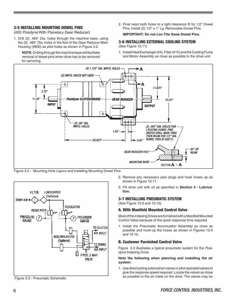
3-5 INSTALLING MOUNTING DOWEL PINS(#20PosidyneWithPlanetaryGearReducer)
�. Drill (2) .484"Dia.holes through themachinebase,usingthe(2).484"Dia.holesinthefeetoftheGearReducerMainHousing(#800)aspilotholesasshowninFigure3.2.
NOTE:Drillingthroughthemachinebasewillfacilitateremovalofdowelpinswhendrivehastoberemovedforservicing.
2. Finalreambothholestoalightclearancefitfor�/2"DowelPins.Install(2)�/2"x�"Lg.RemovableDowelPins.
IMPORTANT: Do not Loc-Tite these Dowel Pins.
3-6 INSTALLING EXTERNAL COOLING SYSTEM(SeeFigure�0.��)
�. InstallHeatExchanger(#4),Filter(#�5)andtheCoolingPumpandMotorAssemblyascloseaspossibletothedriveunit.
2. RemoveanynecessarypipeplugsandhookhosesupasshowninFigure�0.��.
3. Filldriveunitwithoilasspecified inSection 4 - Lubrica-tion.
3-7 INSTALLING PNEUMATIC SYSTEM(SeeFigure�0.9and�0.�0)
A. With Manifold Mounted Control ValveMostoftheIndexingDrivesarefurnishedwithaManifoldMountedControlValvebecauseofthequickresponsetimerequired.
�. Install the Pneumatic Accumulator Assembly as close aspossibleandhook-upthehosesasshowninFigures�0.9and�0.�0.
B. Customer Furnished Control ValveFigure3.3illustratesatypicalpneumaticsystemforthePosi-dyneIndexingDrive.
Note the following when planning and installing the air system:
�. Usedirectactingsolenoidairvalvesorpilotoperatedvalvestogivetheresponsespeedrequired.Locatethevalvesascloseaspossibletotheairinletsonthedrive.ThevalvesmaybeFigure3.3-PneumaticSchematic

7FORCE CONTROL INDUSTRIES, INC.
Section 4 LUBRICATION
4-1 CHECKING THE OIL LEVEL(SeeFigure4.�)
Whenthedriveis installedandweeklythereafter,oruntilex-periencedictatesotherwise,checktheoillevel.Alwayschecktheoillevelwiththedriveatroomtemperatureandwhileitisnotrunning.
ThedrivehasanOilSightGauge(#46)locatedattheoutputendofthedrive.Theoillevelistobeatthecenterofthegaugewiththedrivemotorturnedoff.
ThePlanetaryGearBoxhasaPipePlug(#92)inthesideoftheTransferCase.Removethispipeplugtochecktheoillevel.Theoillevelistobeatthebottomofthehole.
4-2 CHANGING THE OIL(SeeFigures4.�and4.2)
IMPORTANT -Open the disconnects to the drive motors before attempting to change the oil.
A. Posidyne Unit Without External Heat ExchangerEverythreemonthscompletelydraintheoilfromthePosidyneDrivebyremovingaDrainPlug(#73).Draintheoilintoasuit-ablecontainer. If theSightGauge (#46) isdirty, it shouldberemovedandcleaned.
Re-installtheDrainPlug(#73),SightGauge(#46)andremovetheInspectionPlug(#�4)fromtheInputHousing.RefilltheunitwithfreshoiltothecenteroftheSightGauge(#46).
NOTE:Thecapacityofthe#��Posidyneis�0Qts.(2-�/2Gal.)andthe#20Posidynerequires25Qts.(6-�/4Gal.)ofoil.
CAUTION - Do not overfill the Drive Unit. Excess oil will cause the unit to overheat.
Figure4.�-Lubrication
surenecessary.(Theclutchisnotavariablespeeddrive.Donotletitslipforextendedperiods.)Thiswillgiveadditionallifetotheclutch/brake.
5. Afterusingthedriveforafewweekstheaccelerationtimemay increase. Increasing the air pressure will restore theacceleration.
3-8 INSTALLING THE CLPC Model LC CONTROLSee CLPC Model LC Control Operation and Service Manual for Installation, Operation and Servicing.
installeddirectlyonthedriveiftheyaresupported.Besuretousevalvesofatleast2.0Cv.
2. Theoptionalaccumulatorshouldbeusedforquickresponse,particularlyiftheairlinelossandthenatureoftheairsupplyissuchthatrecoveryisslow.Sizetheaccumulatortobeatleast�0timestheairrequiredperengagement(SeeTable2.�)
3. Theairpressureregulatorshouldbesizedandsettoprovidetherequiredtorque.(SeeTable2.�)
4. Pressureisdirectlyproportionaltotorque.Useonlythepres-

FORCE CONTROL INDUSTRIES, INC..8
B. Planetary Gear ReducerAfterinitialinstallationdraintheoilafter30daysandrefillwithfreshoil.Afterfirstoilchangecheckthelevelatleastoncepermonthandchangeatleastevery�2months.
Iftheoil inthePlanetaryGearReducerneedsreplacedthenremove theDrainPlug(#74)anddrain theoil intoasuitablecontainer.Replacethisplugaftertheoilisdrained.
RemovePipePlugs(#�3�)and(#92)andfilltheTransferCaseuntiltheoilstartstocomeoutthe"OilLevelHole"asshowninFigure4.�.TheGearReducerholdapprox.�0Qts.(2-�/2Gal.)ofGearLube.Replacethe(2)PipePlugs(#�3�)and(#92).
C. Posidyne Unit With External Heat Exchanger)(SeeFigures4.2and�0.��)
1. Replacing Filter Element (#16)Checkthepressuredroponthe(2)PressureGauges(#2�6)with theCoolingPumpturnedontosee if theFilterElement(#�6)needstobereplaced.
Ifthepressuredroponthefilteroutletis15 PSI or more,lessthanthefilterinlet,replacetheFilterElement(#�6).FirstturntheCoolingPumpoffthenreplacetheElement.
2. Draining the Oil.a. RemovePipePlug(#45)fromValve "A"andconnectasuit-
ablehosetodraintheoil.
b. TurnthehandleonValve "A"toDrainPositionasshowninFigure4.2.(Valve "B"shouldbeinNormal Position.)Start
theCoolingPumpanddrainoutalloftheoilintoasuitablecontainer.
c. TurnValve "A"back toNormal Positionandreplace thePipePlug(#45).
3. Filling with Oila. RemovethePipePlug(#45)fromValve "B"andconnecta
suitablefillhosetoit.
b. TurnhandleonValve "B"toFill PositionasshowninFigure4.2.MakesurethatValve "A"isinNormal Position.
c. StarttheCoolingPumpandfilltheunituntiltheoilisinthecenteroftheSightGauge(#46)locatedintheoutputhousing.Itshouldtakeapprox.27Qts.tocompletelyfillthesystem.Turnpumpoffwhenfilled.
CAUTION - Do not overfill the Drive Unit. Excess oil will cause the unit to overheat.
d. Turn handle on Valve "B" back to Normal Position andreplacethePipePlug(#45).
4-3 TYPE OF OILUseonlyMobil Automatic Transmission Fluid ATF-210 (type “F”)orMobil Multi-purpose Automatic Transmission FluidformostPosidyneDriveUnits.Otherfluidsmaybespecifiedforspecialapplications.Always use the type of fluid specified on the Name Plate.
ThePlanetaryGearReducerusesHD-80W90 Gear Lube.
Figure4.2-ValvePositionsforDrainingandFillingOil
Filling with OilDraining the Oil
9FORCE CONTROL INDUSTRIES, INC.
Section 5 OPERATIONAL CHECKS
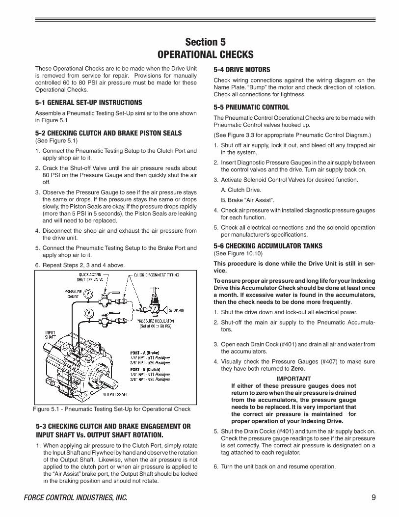
TheseOperationalChecksaretobemadewhentheDriveUnitis removed from service for repair. Provisions for manuallycontrolled60to80PSIairpressuremustbemadefor theseOperationalChecks.
5-1 GENERAL SET-UP INSTRUCTIONSAssembleaPneumaticTestingSet-UpsimilartotheoneshowninFigure5.�
5-2 CHECKING CLUTCH AND BRAKE PISTON SEALS (SeeFigure5.�)
�. ConnectthePneumaticTestingSetuptotheClutchPortandapplyshopairtoit.
2. CracktheShut-offValveuntiltheairpressurereadsabout80PSIonthePressureGaugeandthenquicklyshuttheairoff.
3. ObservethePressureGaugetoseeiftheairpressurestaysthesameordrops.Ifthepressurestaysthesameordropsslowly,thePistonSealsareokay.Ifthepressuredropsrapidly(morethan5PSIin5seconds),thePistonSealsareleakingandwillneedtobereplaced.
4. Disconnecttheshopairandexhausttheairpressurefromthedriveunit.
5. ConnectthePneumaticTestingSetuptotheBrakePortandapplyshopairtoit.
6. RepeatSteps2,3and4above.
5-4 DRIVE MOTORSCheck wiring connections against the wiring diagram on theNamePlate.“Bump”themotorandcheckdirectionofrotation.Checkallconnectionsfortightness.
5-5 PNEUMATIC CONTROLThePneumaticControlOperationalChecksaretobemadewithPneumaticControlvalveshookedup.
(SeeFigure3.3forappropriatePneumaticControlDiagram.)
�. Shutoffairsupply,lockitout,andbleedoffanytrappedairinthesystem.
2. InsertDiagnosticPressureGaugesintheairsupplybetweenthecontrolvalvesandthedrive.Turnairsupplybackon.
3. ActivateSolenoidControlValvesfordesiredfunction.
A.ClutchDrive.
B.Brake“AirAssist".
4. Checkairpressurewithinstalleddiagnosticpressuregaugesforeachfunction.
5. Checkallelectricalconnectionsandthesolenoidoperationpermanufacturer'sspecifications.
5-6 CHECKING ACCUMULATOR TANKS(SeeFigure�0.�0)
This procedure is done while the Drive Unit is still in ser-vice.
To ensure proper air pressure and long life for your Indexing Drive this Accumulator Check should be done at least once a month. If excessive water is found in the accumulators, then the check needs to be done more frequently.
�. Shutthedrivedownandlock-outallelectricalpower.
2. Shut-off the main air supply to the Pneumatic Accumula-tors.
3. OpeneachDrainCock(#40�)anddrainallairandwaterfromtheaccumulators.
4. Visuallycheck thePressureGauges (#407) tomakesuretheyhavebothreturnedtoZero.
IMPORTANTIf either of these pressure gauges does not return to zero when the air pressure is drained from the accumulators, the pressure gauge needs to be replaced. It is very important that the correct air pressure is maintained for proper operation of your Indexing Drive.
5. ShuttheDrainCocks(#40�)andturntheairsupplybackon.Checkthepressuregaugereadingstoseeiftheairpressureissetcorrectly.Thecorrectairpressureisdesignatedonatagattachedtoeachregulator.
6. Turntheunitbackonandresumeoperation.
Figure5.�-PneumaticTestingSet-UpforOperationalCheck
5-3 CHECKING CLUTCH AND BRAKE ENGAGEMENT OR INPUT SHAFT Vs. OUTPUT SHAFT ROTATION.�. WhenapplyingairpressuretotheClutchPort,simplyrotate
theInputShaftandFlywheelbyhandandobservetherotationoftheOutputShaft.Likewise,whentheairpressureisnotappliedtotheclutchportorwhenairpressureisappliedtothe“AirAssist”brakeport,theOutputShaftshouldbelockedinthebrakingpositionandshouldnotrotate.

FORCE CONTROL INDUSTRIES, INC..�0
Section 6 TROUBLESHOOTING
6-1 TROUBLESHOOTING CHART
Bothclutchandbrakefailtoengage Electricalcontrolcircuit. Checkcontrolcircuit.properly. Lowairpressure. Increaseairpressure.** Airpressureregulatororpiping. Checkforimproperoperationorleaks. Wornfrictionsurfaces. Checkpartsforwearandreplaceif necessary.(SeeSection6-2)
Clutchfailstoengageproperly. Electricalcontrolcircuit. Checkcontrolcircuit.
Valvenotfunctioningproperly. Checkvalveoperation.Replaceif necessary.
Internalairleakage. CheckandreplaceO-RingsandLiners ifnecessary.
Lowairpressure Increaseairpressure.**
Wornfrictionsurfaces. Checkpartsforwearandreplaceif necessary.(SeeSection6-2)
Picksuploadtooquickly. Airpressuretoohigh. Reduceairpressure.
Lowoillevel. Checkoillevelandaddifnecessary.
Clutchfailstodisengageproperly. Electricalcontrolcircuit. Checkcontrolcircuit.
Valvenotfunctioningproperly. Checkandreplacevalveifnecessary.
Pistonsticking-brokenreturnsprings. Disassembletoextentnecessaryand inspectfordamagedparts.
Noiseandvibration Mountedonpoorfoundation. Improveinstallation.Tightenfootbolts.
Misalignedcouplings. Recheckalignment.
Damagedbearings. Disassembletoextentnecessaryand inspectfordamagedbearings.
Brakefailstoengageproperly. Electricalcontrolcircuit. Checkcontrolcircuit.
Valvenotfunctioningproperly. Checkvalveoperation.Replaceif necessary.
Internalairleakage. CheckandreplaceO-RingsandLiners ifnecessary.
Lowairpressure Increaseairpressure.**
Wornfrictionsurfaces. Checkpartsforwearandreplaceif necessary.(SeeSection6-2)
REMEDYPOSSIBLE CAUSETROUBLE
��FORCE CONTROL INDUSTRIES, INC.
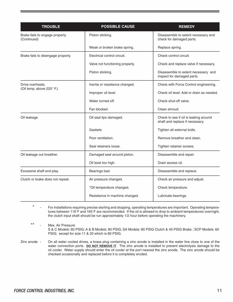
Brakefailstoengageproperly. Pistonsticking. Disassembletoextentnecessaryand(Continued) checkfordamagedparts.
Weakorbrokenbrakespring. Replacespring.
Brakefailstodisengageproperly. Electricalcontrolcircuit. Checkcontrolcircuit.
Valvenotfunctioningproperly. Checkandreplacevalveifnecessary.
Pistonsticking. Disassembletoextentnecessaryand inspectfordamagedparts.
Driveoverheats. Inertiaorresistancechanged. CheckwithForceControlengineering.(Oiltemp.above225°F.) Improperoillevel. Checkoillevel.Addordrainasneeded.
Waterturnedoff. Checkshut-offvalve.
Fanblocked. Cleanshroud.
Oilleakage Oilseallipsdamaged. Checktoseeifoilisleakingaround shaftandreplaceifnecessary.
Gaskets Tightenallexternalbolts.
Poorventilation. Removebreatherandclean.
Sealretainersloose. Tightenretainerscrews.
Oilleakageoutbreather. Damagedsealaroundpiston. Disassembleandrepair.
Oilleveltoohigh. Drainexcessoil.
Excessiveshaftendplay. Bearingsbad. Disassembleandreplace.
Clutchorbrakedoesnotrepeat. Airpressurechanged. Checkairpressureandadjust.
*Oiltemperaturechanged. Checktemperature.
Resistanceinmachinechanged. Lubricatebearings.
TROUBLE POSSIBLE CAUSE REMEDY
* - Forinstallationsrequiringprecisestartingandstopping,operatingtemperaturesareimportant.Operatingtempera-turesbetween��6˚Fand�65˚Farerecommended.Iftheoilisallowedtodroptoambienttemperaturesovernight,theclutchinputshaftshouldberunapproximately�/2hourbeforeoperatingthemachinery.
** - Max.AirPressureS&CModels:60PSIG;A&BModels:80PSIG;SAModels:80PSIGClutch&40PSIGBrake;SCPModels:60PSIG;exceptforsize��&20whichis80PSIG.
Zincanode - Onallwatercooleddrives,abrassplugcontainingazincanodeisinstalledinthewaterlineclosetooneofthewaterconnectionports.DO NOT REMOVE IT. Thezincanodeis installedtopreventelectrolysisdamagetotheoilcooler.Watersupplyshouldentertheoilcoolerattheportnearestthezincanode.Thezincanodeshouldbecheckedoccasionallyandreplacedbeforeitiscompletelyeroded.
FORCE CONTROL INDUSTRIES, INC..�2
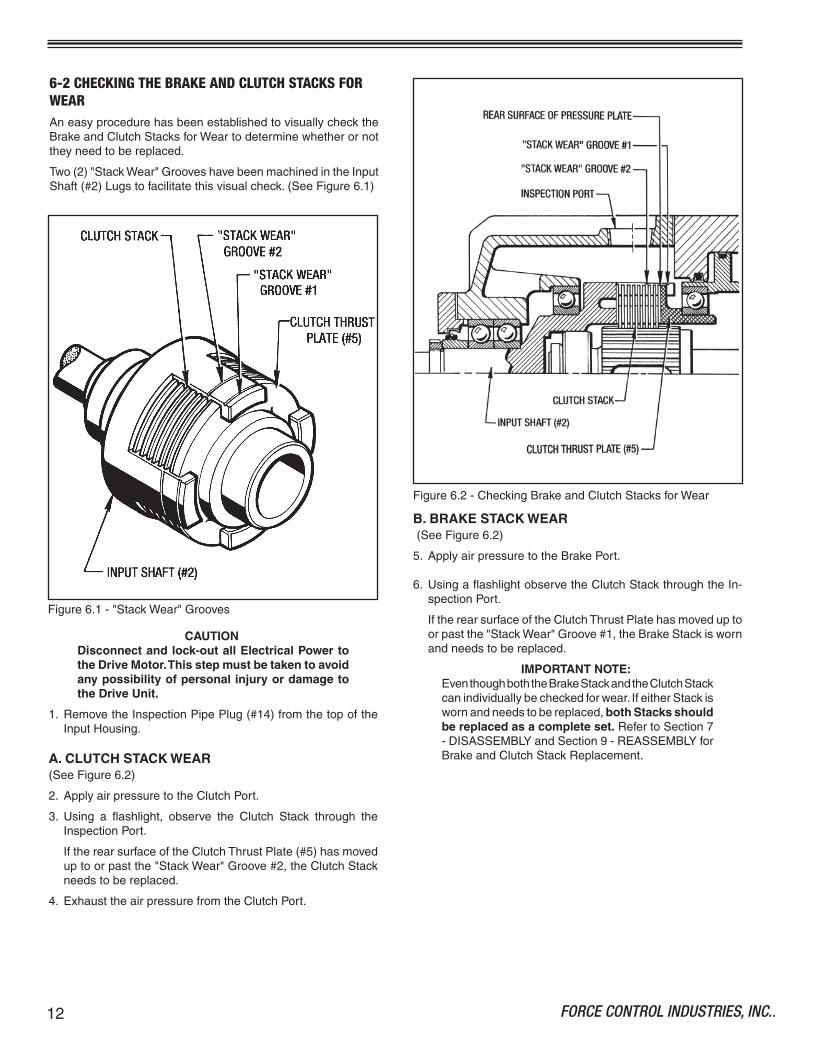
6-2 CHECKING THE BRAKE AND CLUTCH STACKS FOR WEARAneasyprocedurehasbeenestablishedtovisuallychecktheBrakeandClutchStacksforWeartodeterminewhetherornottheyneedtobereplaced.
Two(2)"StackWear"GrooveshavebeenmachinedintheInputShaft(#2)Lugstofacilitatethisvisualcheck.(SeeFigure6.�)
Figure6.2-CheckingBrakeandClutchStacksforWear
Figure6.�-"StackWear"Grooves
CAUTIONDisconnect and lock-out all Electrical Power to the Drive Motor. This step must be taken to avoid any possibility of personal injury or damage to the Drive Unit.
�. RemovetheInspectionPipePlug(#�4)fromthetopoftheInputHousing.
A. CLUTCH STACK WEAR (SeeFigure6.2)
2. ApplyairpressuretotheClutchPort.
3. Using a flashlight, observe the Clutch Stack through theInspectionPort.
IftherearsurfaceoftheClutchThrustPlate(#5)hasmoveduptoorpastthe"StackWear"Groove#2,theClutchStackneedstobereplaced.
4. ExhausttheairpressurefromtheClutchPort.
B. BRAKE STACK WEAR(SeeFigure6.2)
5. ApplyairpressuretotheBrakePort.
6. UsingaflashlightobservetheClutchStackthroughtheIn-spectionPort.
IftherearsurfaceoftheClutchThrustPlatehasmoveduptoorpastthe"StackWear"Groove#�,theBrakeStackiswornandneedstobereplaced.
IMPORTANT NOTE:EventhoughboththeBrakeStackandtheClutchStackcanindividuallybecheckedforwear.IfeitherStackiswornandneedstobereplaced,both Stacks should be replaced as a complete set.RefertoSection7-DISASSEMBLYandSection9-REASSEMBLYforBrakeandClutchStackReplacement.

�3FORCE CONTROL INDUSTRIES, INC.
SCREWS IN REMOVAL POSITION
SCREWS IN LOCKING POSITION
Figure7.�-FlywheelLockingAssemblyRemoval
Toremove theFlywheel (#542)aspecialproceduremustbefollowedtoloosentheLockingAssembly(#540)fromtheInputShaft.(SeeFigure7.�)
2. CompletethefollowingstepstoreleasetheLockingAssembly(#540)fromtheInputShaft.
Step 1 -RemovetheLockingScrewinposition�complete-ly.
Step 2 - Removetheremaining(9)LockingScrewsandinstallthemintothepreviousholesasshowninFigure7.�.
a. MoveScrewinposition3toposition2. b. MoveScrewinposition5toposition4. c. MoveScrewinposition7toposition6. d. MoveScrewinposition9toposition8. e. MoveScrewinposition��toposition�0. f.MoveScrewinposition�3toposition�2. g.MoveScrewinposition�5toposition�4. h. MoveScrewinposition�7toposition�6. i. MoveScrewinposition�9toposition�8.
Step 3 - TightenalloftheseLockingScrewsinanevenman-neruntiltheLockingElementsarereleasedfromtheinputshaft.
7-1 GENERAL DISASSEMBLY PROCEDURE�. DisconnecttheDriveandmoveittoasuitableworkarea.
NOTES:�.OnBeltDrivenorDirectCoupledUnits,removeall necessary safety guards, belts, sheaves andcouplings.
2.Disconnectallnecessarypneumaticpiping.
3.RemoveallexternalhosesandpipingfromExternalCoolingSystemifapplicable.
4.Disconnectthe(2)Brad-HarrisonCables.
2. RemovedrainplugsatthebottomoftheDriveUnitanddrainoutallof theoil intosuitablecontainerandeithersaveforreuseordiscardasconditionswarrants.
NOTES:�.WerecommendthatyousettheDriveUnitontheOutputEndwiththeOutputShaftinaverticaldownposition, foreaseofdisassembly. SupplysuitablebracingandclampingtostabilizetheDriveUnitforDisassembly.2.Anoverheadcraneandasoftslingisalsorecom-mended, if necessary, to remove heavy castingsandparts.
ThePosidyneUnitsarecomprisedof(3)basicsubassembliesandcanbedisassembledascompletesubassembliesforeasyaccesstotheClutch/BrakeStacks.Theexplodedviewdrawingsareasfollows:
�. MAJORSUB-ASSEMBLIESandCLUTCH/BRAKESTACKS(#��and#20PosidyneUnitsWithoutPlanetaryGearReducer)(Figure�0.�)
2. MAJORSUB-ASSEMBLIESandCLUTCH/BRAKESTACKS(#20PosidyneUnitsWithPlanetaryGearReducer)
(Figure�0.2)
3. INPUTHOUSINGASSEMBLY(Figure�0.3)
4. PISTONRETAINERANDHOUSINGASSEMBLY (Figure�0.4)
5. OUTPUTHOUSINGASSEMBLY(Figure�0.5)
6. PLANETARYGEARREDUCER(Figure�0.6)
7. OPENCOLLECTORQUADRATUREENCODER(Magnetic)(Figure�0.7)
8. DIFFERENTIALLINEDRIVERENCODER(Optical) (Figure�0.8)
9. MANIFOLDMOUNTEDCONTROLVALVE(Figure�0.9)
�0.PNEUMATICACCUMULATORASSEMBLY(Figure�0.�0)
��.EXTERNALCOOLINGSYSTEM(Figure�0.��)
7-2 REMOVING FAN, FLYWHEEL AND FAN SHROUD(SeeFigures�0.�or�0.2)
�. TheFan(#543)canberemovedfromtheFlywheel(#542)bytakingoutthe(8)Screws(#475)andpullingitoutoftheFlywheel.
Section 7DISASSEMBLY

FORCE CONTROL INDUSTRIES, INC..�4
3. AttachaslingandoverheadhoisttotheFlywheel(#542)andmanuallybackitofftheInputShaft.
IMPORTANTDo not use any kind of crow bar or lever to back the Flywheel off the input shaft. The Locking As-sembly can get cocked and jammed on the input shaft and get damaged in the process.
4. Removethe(2)Screws(#544)fromtheFanShroud(#24).RemovethetopFlangeNut(#86)andpulltheFanShroud(#24)offtheInputHousing.
7-3 REMOVING QUADRATURE ENCODER (Magnetic)(SeeFigures�0.�or�0.2and�0.7)
�. Ifthe5-PinBradHarrisonCable(#259)isstillattached,dis-connectitatthistime.
2. TaketheHousingCover(#253)offbyremoving(4)Screws(#268).
3. Removethe(4)Screws(#76)and(4)Lockwashers(#257)fromthePick-UpHousing(#�7)andpullthehousingofftheOutputHousing.(SeeFigure�0.�or�0.2)
NOTES:�.Onthe#20Posidynethereareonly(2)Screws(#76)and(2)Lockwashers(#257).
2.On the#��Posidyne there isalsoaGasket(#290)inbehindtheEncoderHousing.Removeitanddiscardit.
4. LoosentheSetScrew(#�54)andpullthePulseGear(#�86)offoftheOutputShaft(#�).
5. Remove both keys (#�8�) and (#234) from the OutputShaft.
NOTE:ThereisnoKey(#234)onthe#��PosidyneDriveUnit.
7-4 REMOVAL OF QUADRATURE SENSOR (#355) and MAGNETIC PICK-UP (#22)(Quadrature Encoder Only)(SeeFigure�0.7)
NOTE:TheQuadratureEncoderAssemblydoesnothavetoberemovedfromtheOutputHousingtoreplacetheSensors.
�. Removethe(4)Screws(#225)andtaketheTopCover(#372)offthePick-UpHousing(#�7).
2. DisconnectthewiresfromtheBradHarrisonCableConnector(#368)tobothSensors.
3. LoosentheSetScrew(#24�)andpulltheMagneticPick-Up(#22)outofthehousing.(Do not remove this set screw.)
4. Removethe(2)Screws(#226)andlifttheQuadratureSensor(#355)outofthehousing.
5. IfanyShims(#2�4)areunderthisSensor,removethemandsaveforReassembly.
7-5 REMOVAL and DISASSEMBLY of DIFFERENTIAL LINE DRIVER ENCODER (Optical Encoder)(SeeFigures�0.�and�0.8)
Figure7.2-CircuitBoardConnector
4. Pull the Cable Grommet (#260), Cable (#259) and CableConnector(#368)outoftheTopEnclosureslot.
5. Removethe(2)CapScrews(#77)andtaketheUpperEn-closure(#�8)andlowerGasket(#�9)offoftheDiscHousing(#�7).Thisgasketisalsoreusable.
6. PulltheCircuitBoard(#355)straightupandoutoftheDiscHousing(#�7).
7. Removethe(4)Screws(#76)and(4)Washers(#32)PulltheDiscHousingoffthePosidynemountingface.
CAUTIONBe very careful not to bump or bend the Optical Disc (#186) which is still attached to the output shaft or damage the Dirt Seal (#269) located in the Disc Housing (#17).
8. If thePosidynestillhas themaindrivingkey in theoutputshaft,removeitatthistime.
9. LoosentheSetScrew(#�54)andpulltheOpticalDiscAs-sembly(#�86)offoftheoutputshaft.
�0.RemovetheKey(#234)fromtheoutputshaft.
��.ChecktheDirtSeal(#269)intheDiscHousing(#�7)andremoveitifitisdamaged.
AnyDriveSheaves,PulleysorCouplingsmustfirstberemovedfromtheoutputshaft.
�. Takeoutthe(4)Screws(#225)andremovetheTopCover(#372)andtheupperGasket(#�9)fromtheUpperEnclosure(#�8).Thisgasketisreusable.
2. PulltheInsulator(#373)upandoutoftheUpperEnclosure(#�8).
3. Loosenthe(2)captivescrewsintheCableConnector(#368)and unplug it from the Circuit Board (#355). (See Figure7.2)
�5FORCE CONTROL INDUSTRIES, INC.
7-6 REMOVING MANIFOLD MOUNTEDCONTROL VALVE (SeeFigure�0.9)
�. DisconnecttheAirHosesandthe4-PinBradHarrisonCableiftheyarestillconnected.
(#11 Posidyne Indexing Drive)2. Unscrew(2)Screws(#725)and(2)Lockwashers(#739)and
lifttheControlValve(#700)offtheManifold(#703).Checkthe(2)O-Rings(#808)andreplaceifnecessary.
3. RemovetheManifoldbytakingoutthe(3)Screws(#726)and(3)Lockwashers(#737).Checkthe(2)O-Rings(#8�2)andreplaceifnecessary.
(#20 Posidyne Indexing Drive)2. Unscrew(4)Screws(#725)and(4)Lockwashers(#739)and
lifttheControlValve(#700)offtheManifold(#703).Checkthe(2)O-Rings(#808)andreplaceifnecessary.
3. RemovetheManifoldbytakingoutthe(3)Screws(#726)and(3)Lockwashers(#737).
4. RemovetheGasket(#807)anddiscardit.
7-7 SEPARATION AND REMOVAL OF MAJOR SUBASSEMBLIES FOR ACCESS TO THE CLUTCH AND BRAKE STACKS
NOTES:�.Jackscrewholesareprovidedtoaidinthesepara-tionofthesubassembliesfromeachother.
2. Do not attempt to reuse the (2) Gaskets (#53).Theymustbereplacedwithnewoneswhenreas-sembled.
3. When removing the Clutch and Brake Stacks,alwayskeeptheDrivePlates(#�3),(#323)andtheFrictionDiscs(#�2)inthesameorderastheywereremoved.
4.On#20PlanetaryIndexingDrivesthePlanetaryGearReducermustalsoberemovedfromtheOutputHousing.(See7-�6forremovalprocedure.)
7-8 CLUTCH AND BRAKE STACKS(SeeFigure�0.�or�0.2)
�. Remove(��)Soc.Hd.CapScrews(#6�)and(��)Lockwash-ers(#�27)fromtheinputendoftheInputHousingSubas-sembly.
2. Usingjackscrews,separateandlifttheInputHousingSubas-semblyawayfromtheDriveUnit.
3. RemoveanddiscardGasket(#53).
4. TheClutchStackcannowberemovedfromtheOutputShaftSpline.
5. Remove(��)Soc.Hd.CapScrews(#69)and(��)Lockwash-ers(#�27)fromtheoutputendoftheOutputHousing.
6. Usingjackscrews,separateandliftthePistonHousingSubas-semblyawayfromtheOutputHousingSubassembly.
7. RemoveanddiscardGasket(#53).
8. TheBrakeStackcannowberemovedfromtheOutputShaftSpline.
IfrepairorreplacementoftheClutchorBrakeStacksaretheonlyrepairtobedone,thenproceedtoSection8CLEANINGANDINSPECTION.
Figure7.3-WearSleeveRemoval(#��PosidyneOnly)
MAJOR SUBASSEMBLIES
7-9 INPUT HOUSING SUBASSEMBLY(SeeFigure�0.3)
(#11 Posidyne)�. Remove(6)Screws(#63)andremoveBearingRetainer(#7),
takingcarenottodamagethelipoftheOilSeal(#3�).
2. CheckOilSeal(#3�)andremoveifitisdamagedandneedstobereplaced.
3. RemoveandcheckO-Ring(#87).
4. Remove theWearSleeve (#4).See7-10 WEAR SLEEVE REMOVAL PROCEDURE.(Figure7.3)
5. RemoveLocknut(#�5)andLockwasher(#�55)ifBearings(#26)or(#35)needtobereplacedthentheInputShafthastobepressedoutoftheInputHousing.
(#20 Posidyne)�. RemoveLocknut(#�5)fromtheInputShaft(#2).
2. Remove(6)Screws(#63)andremovetheBearingRetainer(#7),takingcarenottodamagethelipoftheOilSeal(#3�).
3. CheckOilSeal(#3�)andO-Ring(#87)andreplaceifneces-sary.
4 IftheWearSleeve(#250)needstobereplacedseeSection 7-10 WEAR SLEEVE REMOVAL PROCEDURE. (Figure7.4)
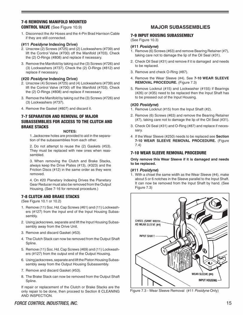
7-10 WEAR SLEEVE REMOVAL PROCEDUREOnly remove this Wear Sleeve if it is damaged and needs to be replaced.
(#11 Posidyne)�. WithachiselthesamewidthastheWearSleeve(#4),make
about5or6notchesintheSleeveparalleltotheInputShaft.ItcannowberemovedfromtheInputShaftbyhand.(SeeFigure7.3)

FORCE CONTROL INDUSTRIES, INC..�6
(#20 Posidyne)�. PulltheMatingRing(#4),withtheWearSleeve(#250)onit,
offtheInputShaft.
2. WithachiselthesamewidthastheWearSleeve(#250)makeabout5or6notchesintheWearSleeve,asshowninFigure7.4.ItcannowberemovedfromtheMatingRingbyhand.
Figure7.4-WearSleeveRemoval(#20PosidyneOnly)
Figure7.6-PistonSub-Assembly
5. UsinganArborPress,removetheClutchThrustPlate(#5)andBearing(#27)fromthePiston(#3).
IMPORTANTOnly remove the Clutch Thrust Plate (#5) and the Bearing (#27) if replacement of either one is necessary.
6. RemoveSprings(#36).ThequantityofSpringsarepre-de-terminedatthefactoryforyourTorqueRequirements.
WhenremovingtheseSprings,itwouldbehelpfulforyoutomakeafreehandsketchlocatingthepositionoftheSprings.ThiswillhelpatReassembly.
7. RemovetheTeflonLiners(#42)andO-Rings(#39)fromthePistonRetainer(#��)andthePistonHousing(#�0).
7-13 OUTPUT HOUSING SUBASSEMBLY(SeeFigure�0.5)
(All Models except #20 Planetary Drives)�. First,removetheKey(#�8�)fromtheOutputShaft(#�)and
placetapeoverthekeyway.
7-12 PISTON HOUSING AND RETAINER SUBASSEMBLY (SeeFigure�0.4)
�. Evenlybackoutandremove(4)Screws(#62)and(4)Lock-washers(#�28).
CAUTIONThe Piston Subassembly is under spring pressure and care must be taken to avoid personal injury when removing these Screws (#62) and separat-ing the Subassembly.
2. SeparatethePistonRetainer(#��)fromthePistonHousing(#�0).RemoveanddiscardGasket(#5�).
3. RemovethePistonSubassemblywhichconsistsof:(a)ThrustPlate(#5),(b)Piston(#3),(c)Bearing(#27),(d)TeflonLiner(#43)and(e)(2)O-Rings(#40).
4. TheTeflonLiner(#43)andthe(2)O-Rings(#40)cannowberemovedforinspectionandreplacement.(SeeFigure7.6)
7-11 REMOVING THE MALE INPUT SHAFT FROM THE INPUT HOUSING (SeeFigure�0.3)
IMPORTANTDo not attempt to remove the Input Shaft unless Bearings (#26) or (#35) need to be replaced.
�. PlacetheInputHousinginanarborpresswiththeInputShaftpointingup.Useappropriatespacers(approximately2-�/2"high)undertheHousing.PresstheInputShaftdownandoutoftheInputHousing.
2. RemoveBearings(#26)fromtheInputHousing.
3. UseaBearingSplittertoremoveBearing(#35)fromtheInputShaft.(SeeFigure7.5).
Figure7.5-RemovingBearingfromtheInputShaft
�7FORCE CONTROL INDUSTRIES, INC.
(#11 Posidyne)2. Remove(6)Screws(#63)andremovetheBearingRetainer
(#7)takingcarenottodamagethelipoftheOilSeal(#3�).AlsochecktoseeifthereisaBearingShim(#378).Ifthereisremoveitfromthebearingbore.
3. CheckOilSeal(#3�)andreplaceifnecessary.
4. RemoveO-Ring(#87)andreplaceifnecessary
5. RemovetheWearSleeve(#4)asshowninFigure7.7anddescribed in WEAR SLEEVE REMOVAL PROCEDURE - Section 7-14.
6. HeatuptheLocknut(#�5)andremoveitandtheLockwasher(#�55)iftheBearings(#26)or(#28)aretobereplacedandtheOutputShaftistobepressedoutoftheOutputHousing.(SeeSection7-�5) CAUTION: Wear suitable gloves when handling heated parts.
(#20 Posidyne)2. HeatupandremoveLocknut(#�5)fromtheOutputShaft(#�).
CAUTION: Wear suitable gloves when handling heated parts.
3. Remove(6)Screws(#63)andremovetheBearingRetainer(#7)takingcarenottodamagethelipoftheOilSeal(#3�).
4. CheckOilSeal(#3�)andreplaceifnecessary.
5. RemoveO-Ring(#87)andreplaceifnecessary
6. PulltheMatingRing(#4),withtheWearSleeve(#250)onit,offoftheOutputShaft(#2)
7. Usethesameprocedureasdescribedin Section 7-10 WEAR SLEEVE REMOVAL PROCEDURE(Figure7.4)toremovetheWearSleeve(#250)fromtheMatingRing(#4).
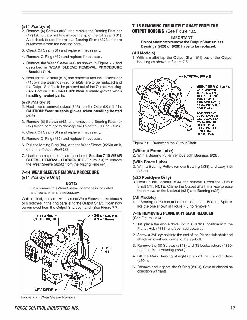
7-14 WEAR SLEEVE REMOVAL PROCEDURE(#11 Posidyne Only)
NOTE:OnlyremovethisWearSleeveifdamageisindicatedandreplacementisnecessary.
Withachisel,thesamewidthastheWearSleeve,makeabout5or6notchesintheringparalleltotheOutputShaft.ItcannowberemovedfromtheOutputShaftbyhand.(SeeFigure7.7)
Figure7.7-WearSleeveRemoval
7-15 REMOVING THE OUTPUT SHAFT FROM THE OUTPUT HOUSING (SeeFigure�0.5)
IMPORTANTDo not attempt to remove the Output Shaft unless Bearings (#26) or (#28) have to be replaced.
(All Models)�. Withamallet tap theOutputShaft (#�)outof theOutput
HousingasshowninFigure7.8.
(Without Force Lube)2. WithaBearingPuller,removebothBearings(#26).
(With Force Lube)2. WithaBearingPuller,removeBearing(#38)andLabyrinth
(#344).
(#20 Posidyne Only)3. Heatup theLocknut (#34)and remove it from theOutput
Shaft(#�).NOTE:ClamptheOutputShaftinavicetoeasetheremovaloftheLocknut(#34)andBearing(#28).
(All Models)4. IfBearing(#28)hastobereplaced,useaBearingSplitter,
liketheoneshowninFigure7.5,toremoveit.
7-16 REMOVING PLANETARY GEAR REDUCER(SeeFigure�0.6)
�. �st.placethewholedriveunitinaverticalpositionwiththePlanetHub(#886)shaftpointedupwards.
2. Screwa3/4"eyeboltintotheendofthePlanetHubshaftandattachanoverheadcranetotheeyebolt.
3. Removethe(8)Screws(#843)and(8)Lockwashers(#850)fromtheMainHousing(#800).
4. Lift theMainHousingstraightupanoff theTransferCase(#80�).
5. RemoveandinspecttheO-Ring(#873).Saveordiscardasconditionwarrants.
Figure7.8-RemovingtheOutputShaft

FORCE CONTROL INDUSTRIES, INC..�8
6. Next install (2) �/2-�3 eyebolts into the upward mountingfaceoftheTransferCase(#80�).Attachtheoverheadcranetotheseeyebolts.
7. Removethe(8)Screws(#843)and(8)Lockwashers(#850)from theTransfer Case (#80�) and lift it off the PosidyneOutputHousingAssembly.
8. RemoveandinspecttheO-Ring(#872).Saveordiscardasconditionwarrants.
9. LoosenuptheLockingScrewsintheShrinkDisc(#822)asdescribedintheB-Loc Removal Instruction SheetonPage52.
�0.Pull theShrinkDisc (#822)andSunGear (#8�9)off thePosidyneOutputShaft.
NOTE:Itmaybenecessarytouseagearpullertogetthegearofftheshaft.
7-17 PLANETARY GEAR REDUCER DISASSEMBLY(SeeFigure�0.6)
A. Removing Bearing Retainer (#803)�. Takeoutthe(4)Screws(#843)and(4)Lockwashers(#850)
andremovetheBearingRetainer(#803). Be careful not to damage the lip of Oil Seal (#824).
2. RemoveanddiscardtheO-Ring(#88�).
3. InspecttheOilSeal(#824)andifitneedsreplaced,pressitoutofthebearingretainerbore.
B. Removing Roller BearingsCAUTION - Do not attempt to remove these roller bearings unless they are damaged and have to be replaced.
�. Take the Locknut (#897) and Lockwasher (#852) off thePlanetHub(#886).YoumayhavetouseheattoloosentheLocknut.
Figure7.9-RemovingPlanetHub(#886) Figure7.��-RemovingWearSleeve(#874)
2. PlacetheremainingassemblyintoanarborpresswiththePlanetHub(#886)shaftinanupwardposition.Useappropri-atespacerstoraisethePlanetHubapprox.2"to3"offthetable.(SeeFigure7.9)
3. PressthePlanetHub(#886)downandoutoftheMainHous-ing(#800).
ThetopBearingCone(#809)willbepushedofftheshaft.ItcanberemovedfromtheMainHousingborebyhand.
ThebottomBearingCone(#8��)willremainontheshaft.UseabearingpullertoremoveitfromthePlanetHubshaft.
4. The(2)BearingCups(#808)areloc-titedintotheMainHous-ingboresandwillhavetobepoundedoutwithastraightbarasshowninFigure7.�0.
Figure7.�0-RemovingBearingCups(#808)
C. Removing Wear Sleeve (#874)�. Withachisel thesamewidthas theWearSleeve (#874),
makeabout5or6notchesasshown inFigure7.��.TheWearSleeve(#874)canthenberemovedbyhand.

�9FORCE CONTROL INDUSTRIES, INC.
D. Removing Planet Gears (#818) to replace Needle Bearings (#812).�. RemovetheSetScrew(#877)asshowninFigure7.�2.This
step is necessary so the Planet Gear Pin (#820) can bepushedoutofthePlanetHub(#886).
PushthePlanetGearPin(#820)outofthePlanetHub(#886)andthePlanetGear(#8�8).
2. Remove the (2)Thrust Washers (#827) and Planet Gear(#8�8).
3. The(2)Spacers(#8�3)canberemovedfromthePlanetGear(#8�8)byhandbuttheNeedleBearing(#8�2)willhavetobepressedoutwithanarborpressandappropriatesizetube.(SeeFigure7.�3)
DothesameprocedureforeachPlanetGeartoberemoved.
THE DISASSEMBLY PROCEDURE FOR YOUR PosidyneINDEXING DRIVE UNIT IS NOW COMPLETE.
Figure7.�2-RemovingPlanetGearPin(#820)
8-1 CLEANING AND INSPECTIONCleanmetalpartsinasuitablesolventanddryinastreamoflowpressurecompressedair.TheClutchandBrakeDrivePlates(#�3) and (#323) can be cleaned in a solvent, but DO NOTcleantheClutchandBrakeFrictionDiscs(#�2)insolvent.Useonlyaclean,dryandlint-freeragtocleantheseFrictionDiscs.(Solventwilldamagetheresilientpaper-basedfrictionmaterialusedontheFrictionDiscs).KeeptheDrivePlatesandFrictionDiscsinthesameorderastheywereremoved.Aftercleaning,inspectpartsforcracks,distortion,scoring,nicks,burrsorotherdamagewouldaffectserviceability.Payparticularattentiontothefollowing:
�. Checkthediscwearsurfacesforscoring,gallingorevidenceofunevenwear.
2. Checktheclutchandbrakeplatesforscoringorgalling.Makesuretheyareflat.Ifaperceptibleridgeisworninanyofthedriveplates,replaceallofthedriveplatesandfrictiondiscsasacompleteset.
3. Carefully check the piston and bore surfaces for nicks,scratches,scoringorotherdamagewhichwouldaffectopera-tionorcauseleakage.
4. PayparticularattentiontoWearSleeve(#250),MatingRing(#4)andWearSleeve(#874)andshaftsintheareaofrotaryseals.Checkfornicks,scratcheswhichwouldcauseleakage.Replaceanydamagedparts.
5. Itisnotnecessarytoremovetheballbearingstochecktheiroperation.Slowlyrotatethefreeraceofeachbearingbyhandcheckingtoseeifitturnsfreelywithoutroughorflatspots.
8-2 REPAIR AND REPLACEMENTAfinestoneorcrocusclothmaybeusedtoremoveminorsurfacedefectsfrompartssolongastheoperatingorsealingactionofthepartisnotaffected.Theuseofcoarserabrasivesorothermachiningmethodsshouldnotbeattempted.Otherwise,dam-agedpartsshouldbereplaced.
Replacement is recommended also for the following, as ap-plicable:
�. ReplaceallO-Rings,Liners,GasketsandOilSealsremovedduringthecourseofdisassembly.
2. ReplaceClutchorBrakeDiscsandDrivePlatesincompletesetsonly.
Section 8 CLEANING and INSPECTION
Figure7.�3-RemovingNeedleBearing(#8�2)

FORCE CONTROL INDUSTRIES, INC..20
Section 9REASSEMBLY
9-1 GENERAL REASSEMBLY INSTRUCTIONS�. LubricateO-RingsandthelipsofalltheOilSealswiththe
sameoilasusedintheDriveUnitimmediatelybeforeReas-semblyandInstallationofanymatingparts.
2. O-RingLiners(#43)willbeeasiertoinstallifheatedinaovento250°F.maximum.
Theinstallationofpressfittedpartscanbeeasedbyheatingtheoutsidepartsinaoven.HeatBearingsto250°F.maximum.
CAUTIONWear suitable gloves when handling heated parts.
3. ApplyGasketSealant(Permatex#30),orequivalent,toallflatgaskets.
4. UseCapScrewAdhesive(Loctite#27�),orequivalent,onallCapScrewsandLocknuts.Usesparinglyandcleanoffanyexcesswith(Loctite(#755)AdhesiveCleaner.
MAJOR SUBASSEMBLIESBasicallytheReassemblyisjustareverseorderoftheDisassemblyProceduredescribedinSection7.
9-2 INSTALLING BEARINGS ON OUTPUT SHAFT(SeeFigure�0.5)
(#11 Posidyne)TodetermineifaBearingShim(#378)isneededfortheoutputshaft,measure the thicknessof the (2)Bearings (#26)whenclampedtogetherasshowninFigure9.�.Ifthebearingsmea-suresmaller than�.9586" forSize#�� thenaBearingShim(#378)willberequired.Ifthebearingsmeasurelargerthanthespecifieddimensions,noshimwillbeneeded. NOTE:ThisShimwillbeinstalledwhentheBearingRetainer(#7)isattachedtothehousing.
Figure9.�-MeasuringThicknessofBearings(#26)
(#11 and #20 Posidyne without Force Lube)�. Press(2)OutboardBearings(#26)ontotheOutputShaft(#�)
usinganArborPress.
IMPORTANT#11 and #20 Posidyne Outboard Bearings (#26) must be installed with the Counterbores facing each other. (SeeFigure9.2)
Figure9.2-InstallingBearings(#26)(WithoutForceLube)
(#20 Posidyne with Force Lube)�. InstalltheLabyrinth(#344)andthenpresstheBearing(#38)
ontotheOutputShaft(#�)
(#11 Posidyne)2. PlaceLockwasher(#�55)ontotheOutputShaftandscrew
Locknut(#�5)ontotheshaft.Use(Loctite#27�)Thread-Lockeronthethreads,Wipeoffanyexcess.
3. PressBearing(#28)ontotheotherendoftheOutputShaft.
4. Press Wear Sleeve (#4) onto the Output Shaft. Also use(Loctite#27�)betweentheshaftandthesleeve.Wipeoffanyexcess.
NOTE:UseWearSleeveAssemblyTool#60�-��-003showninFigure9.5andthesameprocedureshowninFigure9.6topressthisWearSleeve(#4)ontotheOutputShaft.
(#20 Posidyne)2. PlaceO-Ring(#80)ontotheOutputShaft.
3. PressWearSleeve(#250)ontotheMatingRing(#4)Useasealant(Loctite#27�)betweentheWearSleeveandMatingRing.Wipeoffanyexcess.
NOTE:UseWearSleeveAssemblyTool#60�-20-0��showninFigure9.7andthesameprocedureshowninFigure9.8topressthisWearSleeve(#250)ontotheMatingRing(#4).
4. PlaceMatingRingandWearSleeve(#4and#250)ontotheOutputShaft.ScrewLocknut (#�5)onto theOutputShaft.Use(Loctite#27�)Thread-Lockeronthethreads.Wipeoffanyexcess.
5. PressBearing(#28)ontotheotherendoftheOutputShaft.InstallLocknut(#34),usingLoctite#27�onthethreads.Wipeoffanyexcess.
9-3 OUTPUT HOUSING SUBASSEMBLY(SeeFigure�0.5)

2�FORCE CONTROL INDUSTRIES, INC.
(All Models)�. GuidetheOutputShaftSubassemblyintotheOutputHousing
(#9),asshowninFigure9.3.
Figure9.3-InstallingOutputShaftSub-Assembly
2. PresstheOilSeal(#3�)intotheBearingRetainer(#7).Usesealant(Permatex#30)ontheoutsideoftheOilSeal.
(#11 Posidyne)3. LubricateandinstallO-Ring(#87)ontotheshoulderofthe
BearingRetainer(#7).
4. LubricatethelipoftheOilSeal(#3�)andtheMatingRing(#4)withATF-2�0oil.
5. IfitwasdeterminedearlierthataShim(#378)wasneeded,placeitIntothebearingboreandslidetheBearingRetainer(#7),O-Ring(#87)andOilSeal(#3�)ontotheOutputShaft(#�),beingcarefulnottodamagethelipoftheOilSeal.At-tachwith(8)Screws(#63)and(8)Lockwashers(#�28)totheOutputHousing. (See Fig.�0.5 for Torque Specs.)
(#20 Posidyne)3. LubricateandinstallO-Ring(#87)ontotheshoulderofthe
BearingRetainer(#7).
4. LubricatethelipoftheOilSeal(#3�)andtheMatingRing(#4)withATF-2�0oil.
5. SlidetheBearingRetainer(#7),O-Ring(#87)andOilSeal(#3�)ontotheOutputShaft(#�),beingcarefulnottodamagethelipoftheOilSealLip.Attachwith(8)Screws(#63)and(8)Lockwashers(#�28)totheOutputHousing. (See Fig.�0.5 for Torque Specs.)
(All Models)6. ReplaceAirBreather(#45),SightGauge(#46)andanyother
plugsorfittingsremovedatdisassembly.
7. InstallKey(#�8�)backintotheOutputShaftkeyway.
NOTE:ThisKey(#�8�)isnotusedwithaPlanetaryGearReducer.
9-4 PISTON HOUSING AND RETAINER SUBASSEMBLY(SeeFigure�0.4)
�. InstallO-Rings(#39)andLiners(#42)intoPistonRetainer(#��)andPistonHousing(#�0).LubricateO-Ringsbeforeinstallation.
IMPORTANTBefore applying (Loctite #620) to the Bearing (#27) I.D. and O.D. clean it well with (Loctite #755) cleaning solvent or equivalent.
2. ApplySealant(Loctite#620)totheI.D.ofBearing(#27)andpressitontotheThrustPlate(#5).MakesurethattheBearingisfirmlyseatedontheThrustPlateShoulder.
3. Apply Sealant (Loctite #620) to the O.D. of Bearing (#27)andpresstheBearingandThrustPlateintothePiston(#3).Again,makesurethattheBearingisfirmlyseatedagainstthePistonShoulder.
4. Lubricate the (2)O-Rings (#40)and install themonto thePiston(#3).
5. HeattheTeflonLiner(#43)inanovento200°F.maximumandinstallitontheoutsidediameterofthePiston.
6. PlaceSprings(#36),backintotheappropriateholesintheHousingorRetainer.GreasemaybeusedtoholdtheSpringsintheirholesduringassembly.
7. Insert the Piston Subassembly into the Piston Retainer(#�0).
IMPORTANTWhen placing the Piston Retainer over the Piston, be careful not to damage the Teflon Liner (#42) in the Piston Retainer and the Teflon Liner (#43) on the Piston.
8. AlignGasket(#5�)onthePistonHousing,usingtheDowelPins(#68)toensureproperalignment.
9. AssemblethePistonRetainertothePistonHousingwith(4)Screws(#62)and(4)Lockwashers(#�28).
IMPORTANTTighten down Screws (#62) in an even manner to compress the Springs correctly. (SeeFig.�0.4for Torque Specs.)
9-5 INPUT HOUSING SUBASSEMBLY WITH MALE INPUT SHAFT (SeeFigure�0.3)
(All Models)�. PressBearing(#35)ontotheInputShaft(#2).
2. InserttheInputShaft(#2)intotherearoftheInputHousing(#8)untiltheBearing(#35)seatsinthebearingbore.
3. SettheInputHousingSubassemblyintoanArborPressasshowninFigure9.4.Usinganappropriatesizetube,pressonthe innerraceof thefirstBearing(#26)until itbottomsout.(Do not press on the bearing cage of the outer race.) Press thesecondBearing(#26)ontotheInputShaftuntilitisflushwiththefirstBearing
4. ApplyathincoatofSealant(Permatex#30)totheoilsealboreintheBearingRetainer(#7)andpresstheOilSeal(#3�)intotheBearingRetainer.
(#11 Posidyne)5. PlacetheLockwasher(#�55)andtheLocknut(#�5)ontothe
InputShaft(#2).TightentheLocknut.Use(Loctite#27�)onthethreads.Wipeoffanyexcess.
Aspecial Wear Sleeve Assembly ToolmustbeusedtoinstalltheWearSleeve (#4) onto the InputShaft.ThisTool canbeorderedfromForceControlbyusingPart Number 601-11-003.

FORCE CONTROL INDUSTRIES, INC..22
Figure9.4-PressingBearings(#26)intoInputHousing
Figure9.5-WearSleeveAssemblyToolfor#��Posidyne
STEP 1
MachiningDimensionsaregiveninFigure9.5ifyouprefertomakeyourown.
6. PlacetheInputHousingandInputShaftintoanarborpress.UsingSurface "A"oftheAss'y.Tool,presstheWearSleeve(#4)untilitisflushwiththeinputshaftshoulder(SeeFigure9.6Step�).TurntheToolaroundandwithSurface :B" pro-ceedtopresstheWearSleeve(#4)completelyontotheshaftuntilitbottomsoutonthenextshaftshoulder.(SeeFigure9.7Step2).
7. LubricatetheO-Ring(#87)andplaceitontheBearingRe-tainershoulder.
8. PlacetapeoverthekeywayandslidetheBearingRetainer(#7)overtheInputShaft,beingcarefulnottodamagethelipoftheOilSeal(#3�).AttachtheBearingRetainerwith(8)Screws(#63).Torque to 25 Ft. Lbs.
(#20 Posidyne)5. LubricateO-Ring(#80)andinstallitontheInputShaft(#2).
Aspecial Wear Sleeve Assembly ToolmustbeusedtoinstalltheWearSleeve(#250)ontotheMatingRing(#4).ThisToolcanbeorderedfromForceControlbyusingPart Number 601-20-011.MachiningDimensionsarealsogiveninFigure9.7ifyouprefertomakeyourown.
Figure9.6-InstallingWearSleeve(#4)on#��Posidyne
STEP 2
Figure9.7-WearSleeveAssemblyToolfor#20Posidyne

23FORCE CONTROL INDUSTRIES, INC.
6. ApplySealant(Loctite#27�)ontheI.D.oftheWearSleeve(#250)andwithsurface"C"oftheAssemblyToolpresstheWearSleeve(#250)ontotheMatingRing(#4)untilitisflush.Turnthetoolover.Usesurface"D"toseattheWearSleeveproperly.(SeeFigure9.8.)
SIZE MIN. (NeSTACK HEIGHT TABLE
#��. 3.529"(3-�3/32")
SIZE MIN. (Nearest Fraction)
Figure9.9-MeasuringStackHeight
#20 5.578"(5-37/64")
�. Basedon theparts list,place the totalnumberofFrictionDiscsandDrivePlatesinanarborpressasshowninFigure9.9.
2. ClampfirmlyandmeasuretheStackHeight
3. Comparethemeasurementwiththetabulatedvalues(SeeStackHeightTable)and,ifnecessary,addoneortwoFillerPlates(#380)tobringthestackwithinlimitsshown.
NOTE:Alwaysaddtheextrafillerplatetothestacksideawayfromthepiston.Add�st.extrafillerplatetoclutchstackandadd2nd.extrafillerplatetothebrakestack.
9-7 REASSEMBLY OF MAJOR SUBASSEMBLIES AND CLUTCH / BRAKE STACKS (SeeFigure�0.�or�0.2)
�. PlacetheOutputHousinginsuchapositionthatthesplinedendoftheOutputShaftispointedupandtheHousingisonastableflatsurface.
2. InstalltheBrake StackontotheOutputShaftSplineasfol-lows:
AlignthenotchesintheDrivePlateswiththelugsonthePistonRetainerandaligntheinternalteethintheFrictionDiscswiththeteethontheOutputShaftSpline.
a.FirstinstallaFillerPlate(#380)ifitwasrequiredtomaintainthecorrectStackHeightasdescribedinSection9-6.
b.AddaDrivePlate(#�3)andaFrictionDisc(#�2).NOTE:ThisDrivePlate(#�3)doesnothaveanySeparatorSpringsonit.
c.NextaddaDrivePlate(#323)with(4)SeparatorSprings(#377)thenaFrictionDisc(#�2)endingwithaDrivePlate(#323)with(4)SeparatorSprings(#377).Always install the Drive Plates (#323) with the Separator Springs pointed down.
Therewillbe(�)DrivePlate(#�3),(7)DrivePlates(#323)with(4)SeparatorSprings(#377)oneachand(7)FrictionDiscs(#�2)intheBrakeStackplusanyFillerPlates(#380)required.
3. ApplyGasketSealant(Permatex#30)onthematingsurfacesoftheOutputHousingandPistonRetainer.AlignandplaceGasket(#53)ontotheOutputHousing(#9)usingthedowelpinholesforproperalignment.
4. Lower the Piston Housing Subassembly onto the OutputHousing,aligningthelugswiththeslotsintheDrivePlates.PressthePistonHousinguntiltheDowelPins(#68)engagetheOutputHousing.ChecktheGasket(#53)toseeifitisstillproperlyaligned.
5. LaythePistonHousingandOutputHousingSubassemblyoverintoahorizontalpositiononthetable.
6. Use(��)Screws(#69)and(��)Lockwashers(#�27)toattachthePistonHousingtotheOutputHousing.UseThread-Locker(Loctite#27�)onthethreads.Wipeoffanyexcess. (See Fig. 10.1 or 10.2 for Torque Specs.)
Figure9.8-(Step2)InstallingWearSleeve(#250)onMatingRing(#4)for#20Posidyne
7. SlideWearSleeve/MatingRingSubassemblyontotheInputShaft.
8. PlacetapeoverthekeywayandslidetheBearingRetainer(#7)overtheInputShaft,beingcarefulnottodamagethelipoftheOilSeal(#3�).AttachtheBearingRetainerwith(8)Screws(#63).Torque to 60 Ft. Lbs.
9-6 MEASURING AND CONTROLLING STACK HEIGHT DIMENSIONS
Toassurecorrectpistontravel,thefollowingstepsmustbedonewhenreplacingtheClutchandBrakeStacks.

FORCE CONTROL INDUSTRIES, INC..24
Figure9.�0-GapTool
Figure9.��-InsertingGapTool
SIZE "X" MIN. "X" MAX. �� .�00" .�90"
20 .�00 .230
7. StandthePistonHousingandOutputHousingSubassemblybackontheOutputHousingwiththesplinedendoftheOutputShaftpointedup.
8. InstalltheClutch StackontotheOutputShaftSpline,start-ingwithaDrivePlate(#�3)andthenaFrictionDisc(#�2),endingwithaDrivePlate(#�3).AlignthenotchesintheDrivePlateswiththenotchesintheClutchThrustPlate(#5)andaligntheinternalteethintheFrictionDiscswiththeteethontheOutputShaftSpline.
(#11 Posidyne)Therewillbe(��)DrivePlates(#�3)and(�0)FrictionDiscs(#�2)intheBrakeStackplusanyFillerPlates(#380)required.
(#20 Posidyne)Therewillbe(9)DrivePlates(#�3)and(8)FrictionDiscs(#�2)intheBrakeStackplusanyFillerPlates(#380)required.
9. ApplyGasketSealant(Permatex#30)onthematingsurfacesoftheInputHousingandPistonHousing.AlignandpositionGasket(#53)ontothePistonHousing(#�0)usingtheDowelPins(#68)forproperalignment.
�0. Lower the Input Housing Subassembly onto the PistonHousing,aligningthelugsontheInputShaft(#2)withtheslotsintheDrivePlates(#�3)andClutchThrustPlate(#5).PresstheInputHousingdownuntil theDowelPins(#68)engagetheInputHousing.ChecktheGasket(#53)toseeifitisstillproperlyaligned.
��. Use(��)Screws(#6�)and(��)Lockwashers(#�27)toattachtheInputHousingtothePistonHousing.UseThread-Locker(Loctite#27�)onthescrewthreads.Wipeoffanyexcess. (See Fig.�0.�or�0.2 for Torque Specs.)
ThiscompletestheReassemblyProcedurefortheMajorSub-assemblies.Beforeproceedinganyfurther,anOPERATIONAL CHECK oftheClutchandBrakeMovementshouldbemade.Apply60to80PSItotheClutchandBrakePorts,asindicatedinSection 5 - OPERATIONAL CHECKS,andobservethepistonmovementthroughtheinspectionports.
9-8 MEASURING PISTON STROKE�. Aftertheunithasbeencompletelyassembled,settheunit
uprightonatableandapply60PSIairtotheClutchPort.
TomeasurethePistonStrokeaGapTool,asshowninFigure9.�0,mustbeused.ToorderthisGapToolfromtheForceControlfactoryuse(Part No. 601-11-001).
(#11 Posidyne)2. RemovetheAirBreather(#45)andtheSpecialReducerFit-
ting(#2�6)fromthetopoftheOutputHousing.
(#20 Posidyne)2. RemovetheSq.Hd.PipePlug(#�4)fromthetopoftheOutput
Housing.
(All Models)3. Applymachinist'sfastdryinglayoutdieor(useablackmagic
marker)totheslopingsurfaceoftheGapToolasshowninFigure9.�0.
4. FirmlyinserttheGapToolthroughtheinspectionportabovetheBrakeStacksothatanyslackisremovedfromtheBrakeStack. NOTE:ThestraightsideoftheGapToolistowardstheBrakeStack.(SeeFigure9.��)
5. ThesolidshoulderwillscrapethebluingofftheGapToolasshowninFigure9.�2onthenextpage.Togetanaccuratemeasurement,slightlypushtheGapToolsidetosidewhenitisfirmlyinserted.(Thiswillremovethebluinginastraightlineratherthananarc.)
6. Measuredistance"X"withamicrometerasshowninFigure9.�2. Compare the measurement with the tabulated limitsshowninthePistonStrokeTablebelow.
PISTON STROKE TABLE

25FORCE CONTROL INDUSTRIES, INC.
Figure9.�2-MeasuringPistonStroke
9-9 FAN, FAN SHROUD AND FLYWHEEL INSTALLATION(SeeFigure�0.�or�0.2)
�. IfyourdriveunitisFanCooled,attachtheFanShroud(#24)totheInputHousingfeetwith(2)Screws(#544)andtothetopwiththeSetScrew(#88)and(2)FlangedNuts(#86).
2. Position theFlywheel (#542)onto the InputShaftwith thesameproceduredescribedinSection 3 - INSTALLATION; 3-4 - Flywheel InstallationandshowninFigure3.�.
3. TightenuptheB-LocLockingAssembly(#540) intheFly-wheelaccordingtomanufacturer'sspecifications.(See B-Loc Specification Sheet at end of this manual.)
4. AttachCoolingFan(#543)with(8)Screws(#475) intotheFlywheel.
9-10 INSTALLING MANIFOLD MOUNTED CONTROL VALVE (SeeFigure�0.9)
(#11 Posidyne)�. Lubricate the (2)O-Rings (#8�2)andplace them into the
counterboresundertheManifold(#703)
2. AttachManifold(#703)with(3)Screws(#726)and(3)Lock-washers(#737)tothePistonHousing(#�0).
3. AttachtheControlValve(#700)totheManifold(#703)with(2)Screws(#725)and(2)Lockwashers(#739).Also make sure that the (2) O-Rings (#808) are in place under the Control Valve.
4. ReinstallanyHoseFittings,PipeFittingsand theSilencer(#809)thatmayhavebeenremovedatdisassembly.
3. AttachtheEncoderHousing(#�7)totheBearingRetainer(#7)ontheoutputendofthePosidynewith(4)Screws(#76)and(4)Lockwashers(#257).(SeeFigure�0.�)
Jump ahead to Section 9-12 and install the Quadrature Encoder (#355) and the Magnetic Pick-Up (#22).
4. AttachtheTopCover(#372)with(4)Screws(#225)andtheFrontCover(#253)with(4)Screws(#268).
(#20 Posidyne without Planetary Gear Reducer)�. ReplaceKey(#234)intothePosidyneoutputshaftifitwas
removed.
2. SlidethePulseGear(#�86)ontotheoutputshaft.Buttitupagainst theLocknut (#�5)andalign theSetScrew(#�54)withtheKey(#234)andtighten.(SeeFigure9.�4)
(#20 Posidyne)�. Put the Gasket (#807) on the Piston Housing (#�0). Use
(Permatex#30)gasketsealant.Make sure that no sealant gets into the (2) pressure ports.
2. AttachManifold(#703)with(3)Screws(#726)and(3)Lock-washers(#737)tothePistonHousing(#�0).
3. AttachtheControlValve(#700)totheManifold(#703)with(2)Screws(#725)and(2)Lockwashers(#739).Also make sure that the (2) O-Rings (#808) are in place under the Control Valve.
4. ReinstallanyHoseFittings,PipeFittingsand theSilencer(#809)thatmayhavebeenremovedatdisassembly.
9-11 INSTALLING QUADRATURE ENCODER HOUSING AND PULSE GEAR(SeeFigure�0.7)
(#11 Posidyne)�. SlidethePulseGear(#�86)ontotheoutputshaft.Alignthe
SetScrew (#�54)with thedrilledhole in theoutputshaft.PositionthePulseGearasshowninFigure9.�3.TightenSetScrew(#�54).
2. PlacetheGasket(#290)intotherecesseddiameterintherearfaceoftheencoderhousing.Do not use any gasket sealant on this gasket.
Figure9.�3-PulseGearAlignment(#��Posidyne)

FORCE CONTROL INDUSTRIES, INC..26
Figure9.�4-PulseGearAlignment(#20w/oReducer)
3. AttachtheEncoderHousing(#�7)totheBearingRetainer(#7)ontheoutputendofthePosidynewith(2)Screws(#76)and(2)Lockwashers(#257).(SeeFigure�0.�)
Jump ahead to Section 9-12 and install the Quadrature Encoder (#355) and the Magnetic Pick-Up (#22).
4. AttachtheTopCover(#372)with(4)Screws(#225)andtheFrontCover(#253)with(4)Screws(#268).
(#20 Posidyne with Planetary Gear Reducer)�. ReplaceKey(#234)intothePlanetHubShaft(#886)ifitwas
removed.
2. SlidethePulseGear(#�86)ontothePlanetHubShaft(#886).ButtitupagainsttheshaftshoulderandaligntheSetScrew(#�54)withtheKey(#234)andtighten.(SeeFigure9.�5)
Figure9.�5-PulseGearAlignment(#20withReducer)
3. AttachtheEncoderHousing(#�7)totheBearingRetainer(#803).Attachwith(2)Screws(#76)and(2)Lockwashers(#257).(SeeFigure�0.2)
Jump ahead to Section 9-12 and install the Quadrature Encoder (#355) and the Magnetic Pick-Up (#22).
4. AttachtheTopCover(#372)with(4)Screws(#225)andtheFrontCover(#253)with(4)Screws(#268).
9-12 INSTALLING QUADRATURE ENCODER (#355) AND MAGNETIC PICK-UP (#22)(SeeFigure�0.7)
BeforeinstallingtheQuadratureEncoderandMagneticPick-UpaSpecial .0�5"Shimmustbemadetoset theGapbetweenthemandthePulseGear.(SeeFigure9.�6)
Figure9.�6-SensorGapShim
A. QUADRATURE ENCODER (SeeFigure9.22)
�. LookingthroughtheholewheretheEncoder(#355)istobeplaced,checktoseethatthePulseGear(#�86)isinpositionsotheteethwillbealignedwiththeEncoder(#355).
2. PositiontheEncoder(#355)sothe(2)mountingholesarelinedupwiththeholesinthehousing.InserttheSensorintotheslotandattachwith(2)Screws(#226).
NOTES:�.TheholesareoffsettoonesidesotheEncodercanonlybeinstalledoneway.
2.Donot installanyShims(#2�4)at this time. The Gap must be checked first.
3. ChecktheGapbetweenthePulseGearandtheQuadratureEncoder(#355)withtheSpecial.0�5"Shimthatyoumade.Ifnecessary,removetheEncoderandplaceShims(#2�4)undertheEncoder.(Usually.0�5"issufficient.)Re-attachtheEncoder(#355)andre-checktheGap.(SeeFigure9.�7)
4. ConnectthesensorwirestotheBradHarrisonConnector.
B. MAGNETIC PICK-UP SENSOR (SeeFigure9.�7)
�. VisuallycheckthroughtheholetoseeifthesingletoothinthePulseGear(#�86)isalignedwiththeSensor(#22)andthattheteethfortheQuadratureEncoder(#355)willnotbevisibletotheMagneticPick-UpSensor(#22).
TheMagneticPick-UpSensor(#22)hasaScribed Linedownonesideofit.Tofacilitateinstallation,highlightthisScribed Linewithafelttippen.
2. InserttheMagneticPick-UpSensor(#22)intotheholewiththeScribed LineinpositionasshowninFigure9.22,ViewA-A.
3. InserttheSpecial.0�5"ShiminbetweenthePulseGearandtheSensor.TightentheSetScrew(#24�).
4. ConnectthesensorwirestotheBradHarrisonConnector.

27FORCE CONTROL INDUSTRIES, INC.
9-13 REASSEMBLY and INSTALLATION of DIFFERENTIAL LINE DRIVER ENCODER(Optical Encoder)(SeeFigures�0.�and�0.8)
�. InstallKey(#234),thenslidetheOpticalDiscAssembly(#�86)ontotheoutputshaft,buttingitupagainsttheLocknut(#�5).(SeeFigure9.�8)
NOTE:On size��Posidyne theOpticalDiscAssembly(#�86)willbuttupagainsttheoutputshaftshoulder.
2. TightenSetScrew(#�54)andrechecktheHubpositionontheoutputshaft.
Figure9.�7-PositionSensorsInstallation
3. ApplyalightcoatofgreasetotheareaontheHubwheretheDirtSeal(#269)rides.
4. IftheDirtSeal(#269)wasremovedtheninstallitintotheDiscHousing(#�7).
5. AttachtheDiscHousing(#�7)totheoutputendofthePosidynewiththe(4)Screws(#76)and(4)Lockwashers(#257).
6. PlacetheGasket(#�9)ontopoftheDiscHousing.
7. CarefullyinserttheCircuitBoard(#355)intothetopoftheDiscHousingmakingsurethe(3)PhotoInterruptersstraddletheOpticalDisc.(SeeFigures9.�8and9.�9)
8. WhileholdingtheCircuitBoarduprightslidetheUpperEnclo-sure(#�8)downovertheCircuitBoardontotheDiscHousing.MakesuretheedgesoftheCircuitBoardareinthe(2)sideretainingslotslocatedintheUpperEnclosure.(SeeFigure9.�9)
Figure9.�8-OpticalDiscandHubPositioning Figure9.�9-CircuitBoardSlots

FORCE CONTROL INDUSTRIES, INC..28
9. ChecktheGasket(#�9)toseeifitisstillinplace.Insertthe(2)Screws(#77)andtightendown.
�0.SlidetheInsulator(#373)downandintotheUpperEnclosure(#�8)behindtheCircuitBoard(#355)placingtheuppertabsintothecircuitboardslots.(SeeFigure9.�9)
��.Place theCableGrommet (#260)andCable (#259) intotheupperslotandplugintheCableConnector(#368)totheCircuitBoardConnectorandtightenthe(2)CaptiveScrewsintheCableConnector.(SeeFigure9.20)
Figure9.20-CircuitBoardConnector
�2.PlacethetopGasket(#�9)ontheUpperEnclosureandat-tachtheTopCover(#372)with(4)Screws(#225).
9-14 PLANETARY GEAR REDUCER REASSEMBLY(SeeFigure�0.6)
A. Planet Gear Reassembly�. PresstheNeedleBearing(#8�2)intothePlanetGear(#8�8)
withanarborpressuntilitisflushwiththegearface.
2. PlaceaSpacer(#8�3)ontopoftheNeedleBearing(#8�2)andpressitintothegearuntiltheSpacer(#8�3)isflushwiththegearface.(SeeFigure9.2�)
Thiswill insure that theNeedleBearing (#8�2) ispositionedexactlyinthemiddleoftheGear(#8�8).
3. InsertanotherSpacer(#8�3)intotheholeontheothersideoftheBearing(#8�2).PackBearingandSpacerswithMobilith SHC-PM white grease,orequivalent.ThiswillalsoholdtheSpacers(#8�3)inplaceforfurtherreassembly.
Complete this procedure for all (4) four Planet Gears (#818).
4. PlacethePlanetHub(#886)onatablewiththeshaftendpointedup.(SeeFigure9.22)
5. SlideeachassembledPlanetGearintotheopeningwithaThrustWasher (#827)on the topandbottom.Alignall (3)partswiththeplanetgearpinhole.
6. PressthePlanetGearPin(#820)intotheholeuntilitbottomsoutonthetable.Make sure the hole in the Planet Gear Pin (#820) is aligned with the tapped hole in the Planet Hub (#886).
7. ScreweachSetScrew(#877)intothePlanetHub(#886)untilitbottomsout into thehole in thePlanetGearPin(#820).(SeeFigure9.22)Use Blue Loctite #242 and torque to 25 Ft. Lbs.
ThiswillinsurethatthePlanetGearPins(#820)willbeheldinplace.
Figure9.2�-InstallingNeedleBearings(#8�2)
B. Installing Wear Sleeve (#874)(SeeFigure�0.6)
AspecialWearSleeveAssemblyToolmustbeusedtoinstallthisWearSleeve(#874)ontothePlanetHub(#886).
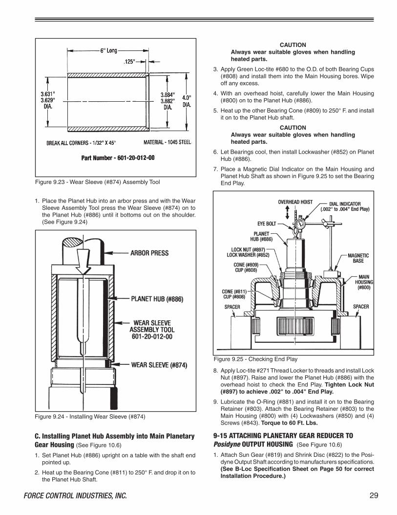
ItcanbeorderedfromForceControl IndustrieswiththePartNumber#60�-20-0�2-00.MachiningDimensionsaregiven inFigure9.23ifyouprefertomakeyourowntool.
Figure9.22-InstallingPlanetGears
29FORCE CONTROL INDUSTRIES, INC.
CAUTIONAlways wear suitable gloves when handling heated parts.
3. ApplyGreenLoc-tite#680totheO.D.ofbothBearingCups(#808)andinstallthemintotheMainHousingbores.Wipeoffanyexcess.
4. Withanoverheadhoist, carefully lower theMainHousing(#800)ontothePlanetHub(#886).
5. HeatuptheotherBearingCone(#809)to250°F.andinstallitontothePlanetHubshaft.
CAUTIONAlways wear suitable gloves when handling heated parts.
6. LetBearingscool,theninstallLockwasher(#852)onPlanetHub(#886).
7. PlaceaMagneticDial Indicatoron theMainHousingandPlanetHubShaftasshowninFigure9.25tosettheBearingEndPlay.
C. Installing Planet Hub Assembly into Main Planetary Gear Housing (SeeFigure�0.6)
�. SetPlanetHub(#886)uprightonatablewiththeshaftendpointedup.
2. HeatuptheBearingCone(#8��)to250°F.anddropitontothePlanetHubShaft.
Figure9.24-InstallingWearSleeve(#874)
�. PlacethePlanetHubintoanarborpressandwiththeWearSleeveAssemblyToolpresstheWearSleeve(#874)ontothePlanetHub(#886)untilitbottomsoutontheshoulder.(SeeFigure9.24)
Figure9.23-WearSleeve(#874)AssemblyTool
8. ApplyLoc-tite#27�ThreadLockertothreadsandinstallLockNut(#897).RaiseandlowerthePlanetHub(#886)withtheoverhead hoist to check the End Play. Tighten Lock Nut (#897) to achieve .002" to .004" End Play.
9. LubricatetheO-Ring(#88�)andinstallitontotheBearingRetainer(#803).AttachtheBearingRetainer(#803)totheMainHousing(#800)with(4)Lockwashers(#850)and(4)Screws(#843).Torque to 60 Ft. Lbs.
9-15 ATTACHING PLANETARY GEAR REDUCER TO Posidyne OUTPUT HOUSING (SeeFigure�0.6)
�. AttachSunGear(#8�9)andShrinkDisc(#822)tothePosi-dyneOutputShaftaccordingtomanufacturersspecifications.(See B-Loc Specification Sheet on Page 50 for correct Installation Procedure.)
Figure9.25-CheckingEndPlay

FORCE CONTROL INDUSTRIES, INC..30
2. Setthe#20Posidynewiththeoutputshaftpointedup.Lu-bricateandinstall(8)O-Ringsintotheoutputhousingfacecounterbores. Also lubricate and install the large O-Ring(#872)intotheO-RingGrooveintheTransferCase(#80�).
3. SettheTransferCase(#80�)ontheoutputhousingusingthe(2)Pins(#876)foralignment.Attachwith(6)Screws(#843)and(6)Lockwashers(#850). Torque to 60 Ft. Lbs.
4. Lubricate(2)O-Rings(#882)and install themover the(2)Pins(#876)inthebackfaceoftheMainHousing(#800).AlsolubricateandinstallthelargeO-Ring(#873)intotheO-RingGrooveinthebackfaceoftheMainHousing(#800).
5. Installaneye-boltintotheendofthePlanetHubshaftandwithanoverheadhoistcarefullylowertheMainHousingandPlanetHubAssemblyontotheTransferCase(#80�).Usethe(2)Pins(#876)foralignment.(SeeFigure9.26)
NOTE:The gear teeth in the (4) Planet Gears (#8�8)havetomeshwiththeinternalgearteethintheTransferCase(#80�)andtheexternalgearteethintheSunGear(8�9).
6. Attachwith(8)Lockwashers(#850)and(8)Screws(#843).Torque to 60 Ft. Lbs.
9-16 FINAL REASSEMBLY�. ReplaceallPipePlugsandFittingsremovedforInspection
orDisassembly.
2. FillthePosidyneClutch/BrakeDriveUnitwithMobilAutomaticTransmissionFluidtypeATF-2�0type"F"orMobilMulti-pur-poseAutomaticTransmissionFluidandthePlanetaryGearReducerwithHD-80W90GearLube,asindicatedinSection 4 - LUBRICATION.
NOTE:Otherfluidsmaybespecifiedforspecialdrives.Always use the same oil as specified on theNamePlate.
3. Replaceallexternalmotordriveparts,safetyguards,sheaves,pulleys,beltsandcouplingsonbeltdriveunits.
4. BeforeplacingtheDriveUnitbackintoservice,completelycheckouttheOperationasdescribedinSection 5 OPERA-TIONAL CHECKS.
REASSEMBLY IS NOW COMPLETE AND THE DRIVE UNIT IS READY FOR SERVICE.
Figure9.26-PlanetaryGearReducerInstallation

3�FORCE CONTROL INDUSTRIES, INC.
Section 10 ILLUSTRATED PARTS LIST
10-1 GENERAL INFORMATIONThissectionillustrates,listsanddescribesallavailablerepairparts for the Force Control Posidyne Clutch/Brake Drives.PartsareidentifiedontheexplodedviewswithPartReferenceNumbers.TheseNumberscorrespondtothePartReferenceNumbergiveninthePartsList.ThePartNameandQuantityUsedisalsogiveninthePartsList.ThisPartReferenceNumber,PartNameandQuantityshouldbeusedwhenorderingparts.
10-2 DRIVE MOTORSThemotorsusedwiththeseDriveUnitsarestandardandmayberepairedorreplacedbyanyqualifiedmotorrebuild facilityorsupplier.
10-3 FACTORY REBUILD SERVICEReconditioningserviceisofferedbyForceControlIndustriesatthefactory.Beforereturningaunitforthisservice,however,besuretofirstcontacttheForceControlIndustriesServiceSalesDepartmentforauthorizationandshippinginstructions.ForceControlIndustriescannotberesponsibleforunitsreturnedtothefactorywithoutpriornoticeandauthorization.
Caremustbegiventothepackingofreturndrives.Alwayspro-tectmountingfeetbyattachingtoaskid.Shipment-damageddrivesalwaysdelayrepairs.Itisusuallyimpossibletorecoverdamagecosts from the carrier. Whenpossible describe theproblemexperiencedonyourshippingpapers.
Returnto: Force Control Industries, Inc. 3660 Dixie Highway Fairfield, Ohio 45014 Telephone: 513-868-0900 Fax No.: 513-868-2105
10-4 ORDERING REPLACEMENT PARTSWhenorderingreplacementparts,pleasespecifyallofthefol-lowinginformation:
�. Drive Model Number(onthenameplate)
2. Drive Serial Number(onthenameplate)
3. Part Reference Number(fromthepartslistorexplodedviewdrawing.)
4. Part Name(fromthepartslist)
5. Quantity (fromthepartslist)
6. Complete Shipping Information
Failuretoincludeinformationforitems�thru6willonlydelayyourpartsorder.Unlessanothermethodisspecifiedforitem6,parts less than�50poundswill beshippedUnitedParcelService,partsover�50poundswillbeshippedMotorFreight.Air freightandother transportationservicesareavailablebutonlyifspecifiedonyourorder.
10-5 NAME PLATE AND MODEL NUMBERS TheNamePlateshownislocatedonthePistonHousing.
Posidyne®Clutch/Brake
Force Control Industries, Inc.
Use Mobil® ATF 210
ModelNo.
SerialNo.
Fairfield,Ohio
ForService/PartsCall513-868-0900
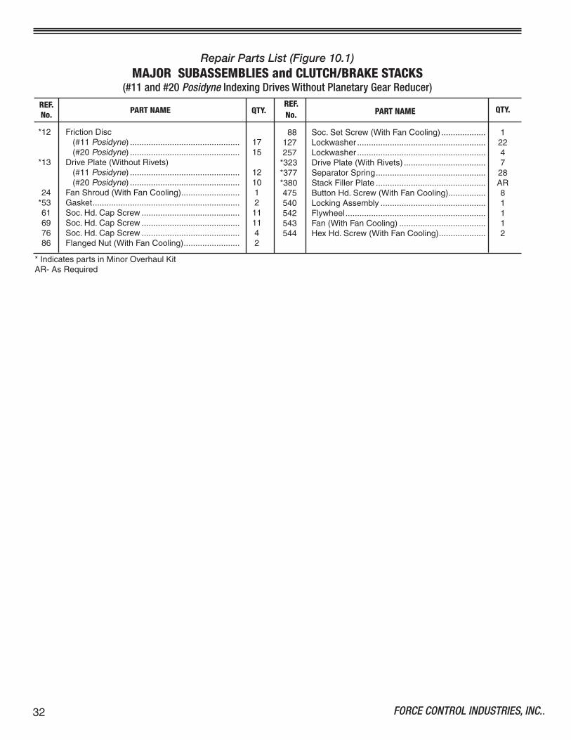
FORCE CONTROL INDUSTRIES, INC..32
Repair Parts List (Figure 10.1)MAJOR SUBASSEMBLIES and CLUTCH/BRAKE STACKS
(#11 and #20 Posidyne Indexing Drives Without Planetary Gear Reducer)
*�2 FrictionDisc (#��Posidyne)............................................... �7 (#20Posidyne)............................................... �5 *�3 DrivePlate(WithoutRivets) (#��Posidyne)............................................... �2 (#20Posidyne)............................................... �0 24 FanShroud(WithFanCooling)......................... � *53 Gasket............................................................... 2 6� Soc.Hd.CapScrew.......................................... �� 69 Soc.Hd.CapScrew.......................................... �� 76 Soc.Hd.CapScrew.......................................... 4 86 FlangedNut(WithFanCooling)........................ 2
PART NAME PART NAME QTY.
88 Soc.SetScrew(WithFanCooling)................... ��27 Lockwasher....................................................... 22257 Lockwasher....................................................... 4*323 DrivePlate(WithRivets)................................... 7*377 SeparatorSpring............................................... 28*380 StackFillerPlate............................................... AR475 ButtonHd.Screw(WithFanCooling)................ 8540 LockingAssembly............................................. �542 Flywheel............................................................ �543 Fan(WithFanCooling)..................................... �544 HexHd.Screw(WithFanCooling).................... 2
REF.No.QTY.
REF.No.
*IndicatespartsinMinorOverhaulKitAR-AsRequired
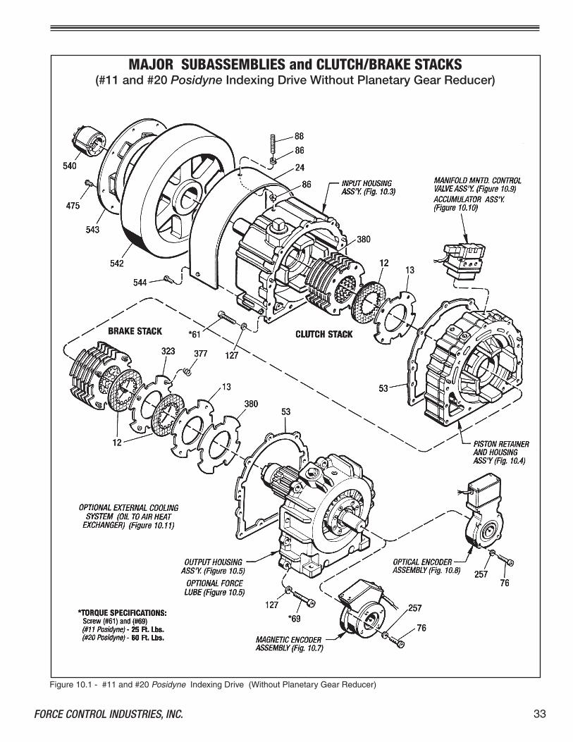
33FORCE CONTROL INDUSTRIES, INC.
Figure�0.�-#��and#20PosidyneIndexingDrive(WithoutPlanetaryGearReducer)
MAJOR SUBASSEMBLIES and CLUTCH/BRAKE STACKS(#11 and #20 Posidyne Indexing Drive Without Planetary Gear Reducer)

FORCE CONTROL INDUSTRIES, INC..34
Repair Parts List (Figure 10.2)MAJOR SUBASSEMBLIES and CLUTCH/BRAKE STACKS
( #20 Posidyne Indexing Drives With Planetary Gear Reducer)
*�2 FrictionDisc...................................................... �5 *�3 DrivePlate(WithoutRivets).............................. �0 24 FanShroud(WithFanCooling)......................... � *53 Gasket............................................................... 2 6� Soc.Hd.CapScrew.......................................... �� 69 Soc.Hd.CapScrew.......................................... �� 76 Soc.Hd.CapScrew.......................................... 4 86 FlangedNut(WithFanCooling)........................ 2 88 Soc.SetScrew(WithFanCooling)................... ��27 Lockwasher....................................................... 22
PART NAME PART NAME QTY.
257 Lockwasher....................................................... 4*323 DrivePlate(WithRivets)................................... 7*377 SeparatorSpring............................................... 28*380 StackFillerPlate............................................... AR475 ButtonHd.Screw(WithFanCooling)................ 8540 LockingAssembly............................................. �542 Flywheel............................................................ �543 Fan(WithFanCooling)..................................... �544 HexHd.Screw(WithFanCooling).................... 2
REF.No.QTY.
REF.No.
*IndicatespartsinMinorOverhaulKitAR-AsRequired

35FORCE CONTROL INDUSTRIES, INC.
Figure�0.2-#20PosidyneIndexingDrive(WithPlanetaryGearReducer)
MAJOR SUBASSEMBLIES and CLUTCH/BRAKE STACKS(#20 Posidyne Indexing Drive With Planetary Gear Reducer)

FORCE CONTROL INDUSTRIES, INC..36
Figure�0.3-InputHousingAssembly
Repair Parts List (Figure 10.3)INPUT HOUSING SUBASSEMBLY
2 InputShaft........................................................ � *4 MatingRing(#20Only)..................................... � *4 WearSleeve(#��Only).................................... � 7 BearingRetainer............................................... � 8 InputHousing.................................................... � �4 Sq.Hd.PipePlug.............................................. �**�5 Locknut.............................................................. � *26 BallBearing....................................................... 2 *3� OilSeal............................................................. � *35 BallBearing....................................................... �
REF.No.
PART NAME QTY. PART NAMEREF.No.
63 Soc.Hd.CapScrew.......................................... 6 68 DowelPin......................................................... 2 73 Mag.HdPipePlug............................................ 2 75 WaterPortPlug................................................. 2 *80 O-Ring(#20Only)............................................. � *87 O-Ring............................................................... ��55 Lockwasher(#��Only)..................................... �2�3 RollPin(#20only)............................................. �*250 WearSleeve(#20Only).................................... �
*-IndicatespartsinMinorOverhaulKit.**-IndicatespartsinMajorOverhaulKit.(PlusallpartsinMinorOverhaulKit.)
QTY.
INPUT HOUSING ASSEMBLY

37FORCE CONTROL INDUSTRIES, INC.
Figure�0.4-PistonRetainerandHousingAssembly
REF.No. QTY.PART NAME
REF.No. PART NAME QTY.
3 Piston................................................................ � **5 ClutchThrustPlate............................................ � �0 PistonHousing.................................................. � �� PistonRetainer................................................. � *27 BallBearing....................................................... � *36 CompressionSpring........................................ 8 *39 O-Ring............................................................... 2
*40 O-Ring............................................................... 2 *42 I.D.SealingLiner............................................... 2 *43 O.D.SealingLiner............................................. � *5� HousingGasket................................................. � 62 Soc.Hd.CapScrew.......................................... 4 68 DowelPin.......................................................... 4�28 Lockwasher,5/�6"............................................. 4
Repair Parts List (Figure 10.4)PISTON RETAINER AND HOUSING ASSEMBLY
PISTON RETAINER AND HOUSING ASSEMBLY
*-IndicatesPartsinMinorOverhaulKit**-IndicatesPartsinMajorOverhaulKit.(PlusallpartsinMinorOverhaulKit.)
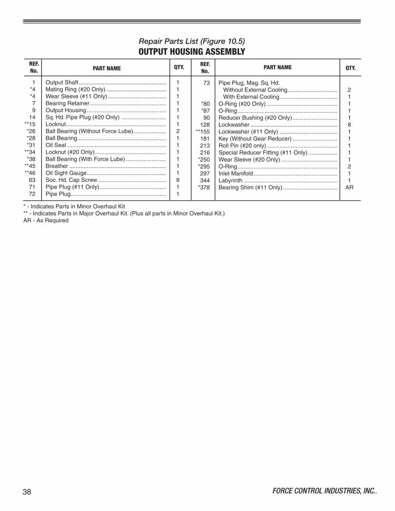
FORCE CONTROL INDUSTRIES, INC..38
Repair Parts List (Figure 10.5)OUTPUT HOUSING ASSEMBLY
� OutputShaft...................................................... � *4 MatingRing(#20Only)..................................... � *4 WearSleeve(#��Only).................................... � 7 BearingRetainer............................................... � 9 OutputHousing................................................. � �4 Sq.Hd.PipePlug(#20Only)............................ �**�5 Locknut.............................................................. � *26 BallBearing(WithoutForceLube).................... 2 *28 BallBearing....................................................... � *3� OilSeal............................................................. �**34 Locknut(#20Only)............................................ � *38 BallBearing(WithForceLube)......................... �**45 Breather............................................................ �**46 OilSightGauge................................................. � 63 Soc.Hd.CapScrew.......................................... 8 7� PipePlug(#��Only)......................................... � 72 PipePlug........................................................... �
REF.No. PART NAME QTY. PART NAME QTY.
73 PipePlug,Mag.Sq.Hd. WithoutExternalCooling............................... 2 WithExternalCooling.................................... � *80 O-Ring(#20Only)............................................ � *87 O-Ring.............................................................. � 90 ReducerBushing(#20Only)............................ � �28 Lockwasher...................................................... 8**�55 Lockwasher(#��Only).................................... � �8� Key(WithoutGearReducer)............................ � 2�3 RollPin(#20only)............................................ � 2�6 SpecialReducerFitting(#��Only).................. � *250 WearSleeve(#20Only)................................... � *295 O-Ring.............................................................. 2 297 InletManifold.................................................... � 344 Labyrinth.......................................................... � *378 BearingShim(#��Only).................................. AR
REF.No.
*-IndicatesPartsinMinorOverhaulKit**-IndicatesPartsinMajorOverhaulKit.(PlusallpartsinMinorOverhaulKit.)AR-AsRequired

39FORCE CONTROL INDUSTRIES, INC.
OUTPUT HOUSING ASSEMBLY
Figure�0.5-OutputHousingAssembly

FORCE CONTROL INDUSTRIES, INC..40
Repair Parts List (Figure 10.6)PLANETARY GEAR REDUCER
**45 Breather............................................................ � 74 PipePlug,3/4"Sq.Hd.Mag.............................. 2 92 PipePlug,3/4"................................................. 3��7 StreetElbow,3/4"NPT..................................... ��3� PipePlug,3/4"Sq.Hd....................................... �800 MainHousing.................................................... �80� TransferCase.................................................... �803 BearingRetainer............................................... �*808 BearingCup...................................................... 2*809 BearingCone.................................................... �*8�� BearingCone.................................................... �*8�2 NeedleBearing................................................. 48�3 Spacer............................................................... 88�8 PlanetGear....................................................... 48�9 SunGear........................................................... �820 PlanetGearPin................................................. 4822 ShrinkDisc........................................................ � *824 OilSeal............................................................. �
*827 ThrustWasher.................................................. 8 830 ReducerBushing,�/2"x�/4"........................... � 840 Key................................................................... � 843 Soc.Hd.CapScrew,�/2"-�3x�-3/4"Lg.......... 20 850 Lockwasher...................................................... 20**852 Lockwasher...................................................... � *872 O-Ring.............................................................. � *873 O-Ring.............................................................. � *874 WearSleeve..................................................... � 876 DowelPin......................................................... 4 877 SetScrew English,�/2"-�3x�-�/2"Lg............................ 4 Metric,M�2-�.75x40mmLg........................ 4 *88� O-Ring.............................................................. � *882 O-Ring.............................................................. �2 886 PlanetHub....................................................... �**897 LockNut........................................................... �
REF REF No. PART NAME QTY. No. PART NAME QTY.
*-IndicatespartsinMinorOverhaulKit.**-IndicatespartsinMajorOverhaulKitplusallpartsinMinorOverhaulKit.

4�FORCE CONTROL INDUSTRIES, INC.
Figure�0.6-PlanetaryGearReducer
PLANETARY GEAR REDUCER
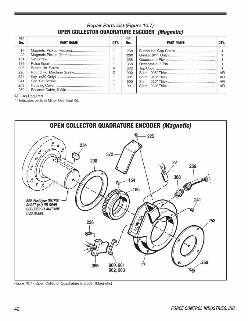
FORCE CONTROL INDUSTRIES, INC..42
Figure�0.7-OpenCollectorQuadratureEncoder(Magnetic)
Repair Parts List (Figure 10.7)OPEN COLLECTOR QUADRATURE ENCODER (Magnetic)
�7 MagneticPickupHousing.................................. � 22 MagneticPickup(Home)................................... ��54 SetScrew.......................................................... ��86 PulseGear........................................................ �225 ButtonHd.Screw.............................................. 4226 RoundHd.MachineScrew................................ 2234 Key(#20Only)................................................. �24� Soc.SetScrew.................................................. �253 HousingCover.................................................. �259 EncoderCable,5Wire...................................... �
268 ButtonHd.CapScrew....................................... 4*290 Gasket(#��Only)............................................. �355 QuadraturePickup............................................ �368 Receptacle,5-Pin.............................................. �372 TopCover.......................................................... �900 Shim,.005"Thick.............................................. AR90� Shim,.0�0"Thick.............................................. AR900 Shim,.020"Thick.............................................. AR90� Shim,.030"Thick.............................................. AR
REF REF No. PART NAME QTY. No. PART NAME QTY.
AR-AsRequired.*-IndicatespartsinMinorOverhaulKit.
OPEN COLLECTOR QUADRATURE ENCODER (Magnetic)
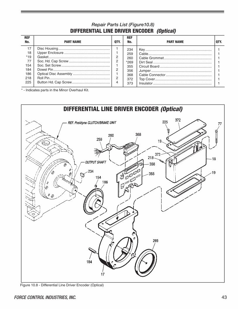
43FORCE CONTROL INDUSTRIES, INC.
Figure�0.8-DifferentialLineDriverEncoder(Optical)
REF REF No. PART NAME QTY. No. PART NAME QTY.
Repair Parts List (Figure10.8)DIFFERENTIAL LINE DRIVER ENCODER (Optical)
DIFFERENTIAL LINE DRIVER ENCODER (Optical)
234 Key.................................................................... �259 Cable................................................................. �260 CableGrommet................................................. �*269 DirtSeal............................................................ �355 CircuitBoard..................................................... �356 Jumper.............................................................. �368 CableConnector............................................... �372 TopCover.......................................................... �373 Insulator............................................................ �
�7 DiscHousing..................................................... � �8 UpperEnclosure............................................... � *�9 Gasket............................................................... 2 77 Soc.Hd.CapScrew.......................................... 2�54 Soc.SetScrew.................................................. ��84 DowelPin.......................................................... 2�86 OpticalDiscAssembly...................................... �2�8 RollPin.............................................................. 2225 ButtonHd.CapScrew....................................... 4
*-IndicatespartsintheMinorOverhaulKit.
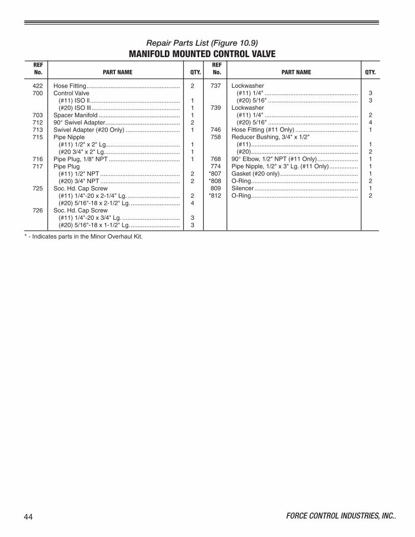
FORCE CONTROL INDUSTRIES, INC..44
Repair Parts List (Figure 10.9)MANIFOLD MOUNTED CONTROL VALVE
REF REF No. PART NAME QTY. No. PART NAME QTY.
737 Lockwasher (#��)�/4"....................................................... 3 (#20)5/�6"..................................................... 3739 Lockwasher (#��)�/4"....................................................... 2 (#20)5/�6"..................................................... 4746 HoseFitting(#��Only)..................................... �758 ReducerBushing,3/4"x�/2" (#��)............................................................... � (#20)............................................................... 2768 90°Elbow,�/2"NPT(#��Only)........................ �774 PipeNipple,�/2"x3"Lg.(#��Only)................. �*807 Gasket(#20only).............................................. �*808 O-Ring............................................................... 2809 Silencer............................................................. �*8�2 O-Ring............................................................... 2
422 HoseFitting....................................................... 2700 ControlValve (#��)ISOll..................................................... � (#20)ISOlll.................................................... �703 SpacerManifold................................................ �7�2 90°SwivelAdapter............................................ 27�3 SwivelAdapter(#20Only)................................ �7�5 PipeNipple (#��)�/2"x2"Lg............................................ � (#203/4"x2"Lg............................................. �7�6 PipePlug,�/8"NPT.......................................... �7�7 PipePlug (#��)�/2"NPT............................................... 2 (#20)3/4"NPT............................................... 2725 Soc.Hd.CapScrew (#��)�/4"-20x2-�/4"Lg................................ 2 (#20)5/�6"-�8x2-�/2"Lg.............................. 4726 Soc.Hd.CapScrew (#��)�/4"-20x3/4"Lg................................... 3 (#20)5/�6"-�8x�-�/2"Lg.............................. 3
*-IndicatespartsintheMinorOverhaulKit.

45FORCE CONTROL INDUSTRIES, INC.
Figure�0.9-ManifoldMountedControlValve
MANIFOLD MOUNTED CONTROL VALVE(#11 Posidyne INDEXING DRIVE)
(#20 Posidyne INDEXING DRIVE)
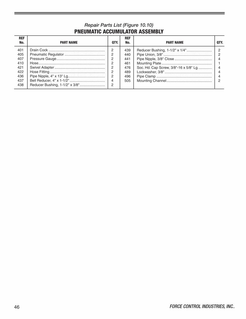
FORCE CONTROL INDUSTRIES, INC..46
Repair Parts List (Figure 10.10)PNEUMATIC ACCUMULATOR ASSEMBLY
40� DrainCock........................................................ 2405 PneumaticRegulator........................................ 2407 PressureGauge................................................ 24�0 Hose.................................................................. 242� SwivelAdapter.................................................. 2422 HoseFitting....................................................... 2436 PipeNipple,4"x�3"Lg..................................... 2437 BellReducer,4"x�-�/2"................................... 4438 ReducerBushing,�-�/2"x3/8"......................... 2
REF REF No. PART NAME QTY. No. PART NAME QTY.
439 ReducerBushing,�-�/2"x�/4"......................... 2440 PipeUnion,3/8"................................................ 244� PipeNipple,3/8"Close..................................... 446� MountingPlate.................................................. �476 Soc.Hd.CapScrew,3/8"-�6x5/8"Lg.............. 4489 Lockwasher,3/8"............................................... 4496 PipeClamp....................................................... 4505 MountingChannel............................................. 2

47FORCE CONTROL INDUSTRIES, INC.
Figure�0.�0-PneumaticAccumulatorAssembly
PNEUMATIC ACCUMULATOR ASSEMBLY
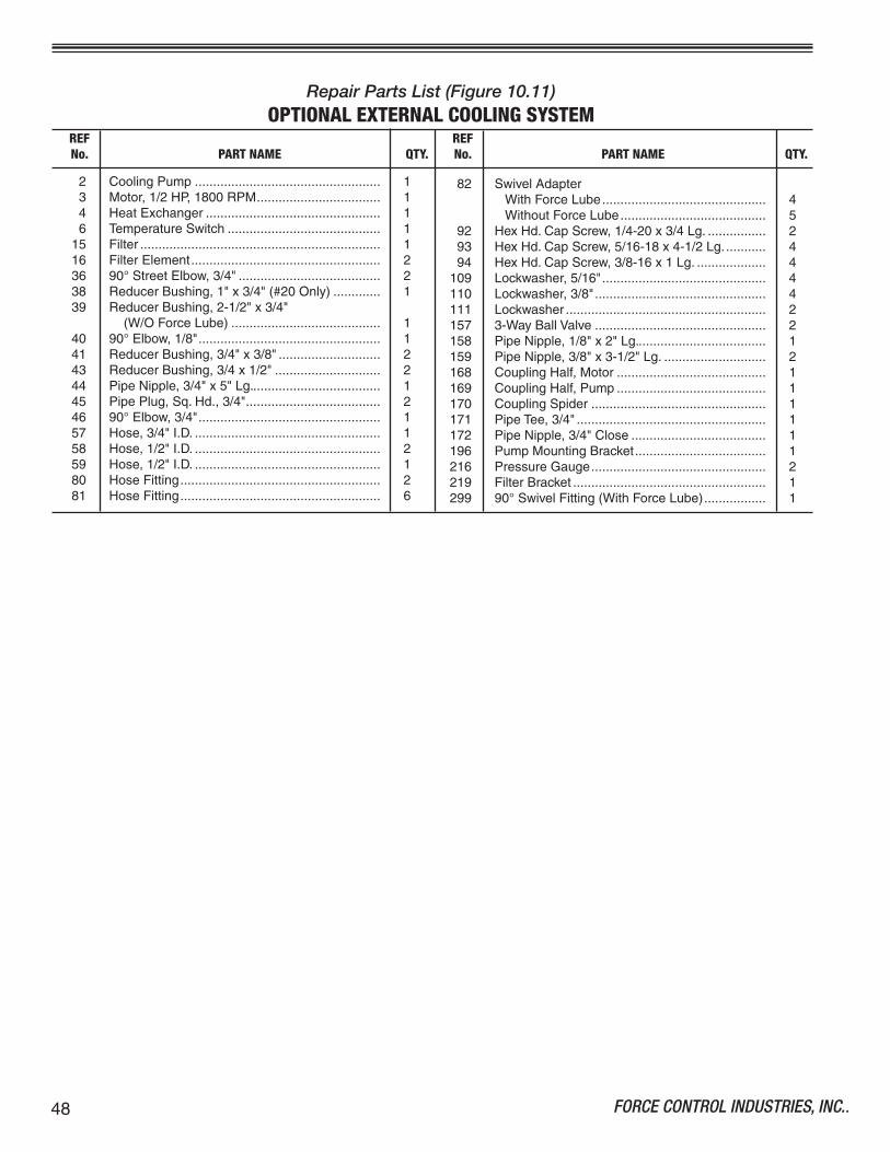
FORCE CONTROL INDUSTRIES, INC..48
Repair Parts List (Figure 10.11)OPTIONAL EXTERNAL COOLING SYSTEM
2 CoolingPump................................................... � 3 Motor,�/2HP,�800RPM.................................. � 4 HeatExchanger................................................ � 6 TemperatureSwitch.......................................... � �5 Filter.................................................................. � �6 FilterElement.................................................... 2 36 90°StreetElbow,3/4"....................................... 2 38 ReducerBushing,�"x3/4"(#20Only)............. � 39 ReducerBushing,2-�/2"x3/4" (W/OForceLube)......................................... � 40 90°Elbow,�/8".................................................. � 4� ReducerBushing,3/4"x3/8"............................ 2 43 ReducerBushing,3/4x�/2"............................. 2 44 PipeNipple,3/4"x5"Lg.................................... � 45 PipePlug,Sq.Hd.,3/4"..................................... 2 46 90°Elbow,3/4".................................................. � 57 Hose,3/4"I.D.................................................... � 58 Hose,�/2"I.D.................................................... 2 59 Hose,�/2"I.D.................................................... � 80 HoseFitting....................................................... 2 8� HoseFitting....................................................... 6
82 SwivelAdapter WithForceLube............................................. 4 WithoutForceLube........................................ 5 92 HexHd.CapScrew,�/4-20x3/4Lg................. 2 93 HexHd.CapScrew,5/�6-�8x4-�/2Lg............ 4 94 HexHd.CapScrew,3/8-�6x�Lg.................... 4�09 Lockwasher,5/�6"............................................. 4��0 Lockwasher,3/8"............................................... 4��� Lockwasher....................................................... 2�57 3-WayBallValve............................................... 2�58 PipeNipple,�/8"x2"Lg.................................... ��59 PipeNipple,3/8"x3-�/2"Lg............................. 2�68 CouplingHalf,Motor......................................... ��69 CouplingHalf,Pump......................................... ��70 CouplingSpider................................................ ��7� PipeTee,3/4".................................................... ��72 PipeNipple,3/4"Close..................................... ��96 PumpMountingBracket.................................... �2�6 PressureGauge................................................ 22�9 FilterBracket..................................................... �299 90°SwivelFitting(WithForceLube)................. �
REF REF No. PART NAME QTY. No. PART NAME QTY.

49FORCE CONTROL INDUSTRIES, INC.
OPTIONAL EXTERNAL COOLING SYSTEM(OIL TO AIR HEAT EXCHANGER)
Figure�0.��-ExternalCoolingSystem
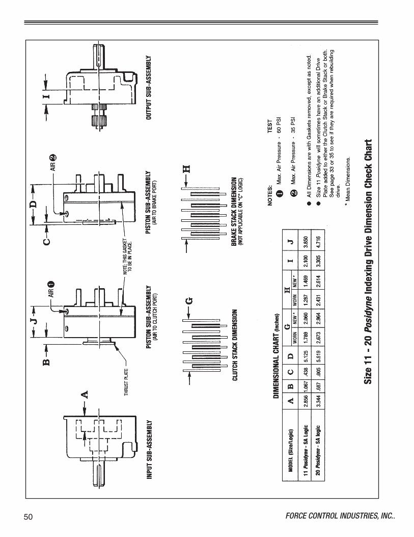
FORCE CONTROL INDUSTRIES, INC..50

5�FORCE CONTROL INDUSTRIES, INC.
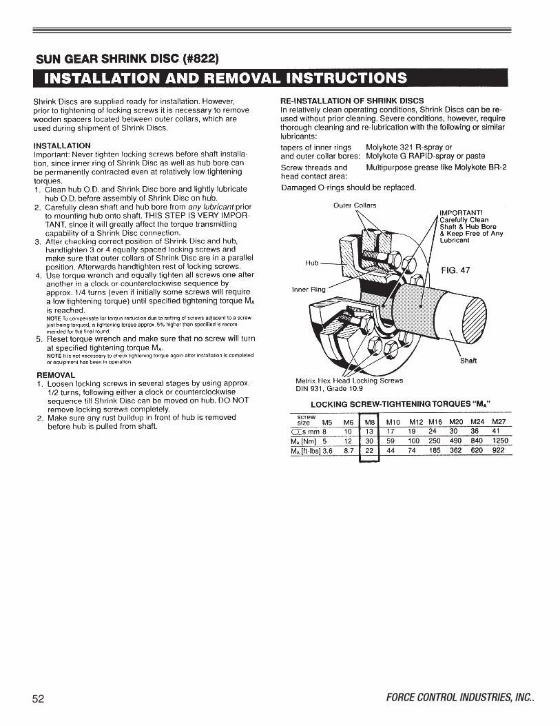
FORCE CONTROL INDUSTRIES, INC..52

FORCE CONTROL INDUSTRIES, Inc.
Providing todays industrieswith Oil Shear Clutch andBrake Drives that deliver...• Flexibility • Efficiency
• Endurance • Performanceand • Dependability
Force Control Industries, Inc.3660 Dixie HighwayFairfield, OH 45014
513-868-0900 phone513-868-2105 fax
www.forcecontrol.com
"Built to Last - Guaranteed to Perform"