50w ku-band hub-mount solid state power amplifier awsa … · 50w ku-band hub-mount solid state...
TRANSCRIPT

INSTALLATION AND OPERATING MANUAL
50W Ku-BAND HUB-MOUNT
SOLID STATE POWER AMPLIFIER
AWSA-K50-CHE
PM 100-432350-530, REV. 1

AWSA-K50-CHE
Page 1
WARRANTY This ADVANTECH Advanced Microwave Technologies, Inc. product is warranted against defects in material and workmanship for a period of 2 years from date of shipment. During the warranty period, ADVANTECH Advanced Microwave Technologies, Inc. will, at its option, either repair or replace products that will prove to be defective. To return a product for warranty or repair service, you must first request a Return Material Authorization (RMA) number by contacting ADVANTECH at: Phone: (514) 420-0045 or Fax: (514) 420-0073 Website: www.AdvantechAMT.com or e-mail: [email protected] The unit should be shipped to the following address, in original shipping container (box), with shipping charges prepaid. ADVANTECH Advanced Microwave Technologies, Inc. 657 Orly Avenue Dorval, Quebec H9P 1G1 CANADA Please indicate the RMA number on all shipping documentation. Units shipped without prior issued RMA, or shipped not in original packing, may be subject of rejection and returned at sender’s own expense.
LIMITATIONS OF WARRANTY ADVANTECH Advanced Microwave Technologies, Inc. warrants this product to be free of materials and workmanship defects. The foregoing warranty shall not apply to defects resulting from improper handling or abuse by the Buyer, unauthorized modification, operation outside of the environmental specifications for the product, or improper installation or maintenance. ADVANTECH Advanced Microwave Technologies, Inc. shall not be liable for any direct, indirect, special, incidental or consequential damages.

AWSA-K50-CHE
Page 2
CONTENTS
1. PACKING LIST ..................................................................................................................................................5
2. SAFETY ...............................................................................................................................................................6
3. GENERAL INFORMATION.............................................................................................................................8
3.1 ELECTRICAL SPECIFICATIONS.........................................................................................................................9
4. MAJOR SUBSYSTEMS AND THEIR FUNCTIONS ...................................................................................12
4.1 RF SUBSYSTEM ............................................................................................................................................12 4.2 POWER SUPPLY SUBSYSTEM.........................................................................................................................15 4.3 ALARM/INDICATE BOARD ............................................................................................................................15
5. UNPACKING AND INSTALLATION............................................................................................................16
5.1 INITIAL INSPECTION......................................................................................................................................16 5.2 UNPACKING..................................................................................................................................................16 5.3 INSTALLATION..............................................................................................................................................16
5.3.1 Mechanical Installation .......................................................................................................................16 5.3.2 Electrical Connections.........................................................................................................................17 5.3.3 RF Connections ...................................................................................................................................18 5.3.4 Cooling Considerations .......................................................................................................................19
6. INTERFACES ...................................................................................................................................................20
6.1 DISCRETE INTERFACE...................................................................................................................................20 6.1.1 Functional Description ........................................................................................................................21
6.2 RF OUTPUT MONITOR PORT ........................................................................................................................21
7. INITIAL POWER ON AND CHECKOUT.....................................................................................................22
7.1 PRE-POWER PROCEDURES ............................................................................................................................22
8. OPERATION.....................................................................................................................................................23
8.1 ESSENTIAL OPERATING PROCEDURES ..........................................................................................................23
9. MAINTENANCE...............................................................................................................................................24
9.1 PREVENTIVE MAINTENANCE ........................................................................................................................24 9.1.1 Mechanical Preventive Maintenance...................................................................................................24 9.1.2 Checking the Cooling Fan ...................................................................................................................24
10. APPENDIX A: SAFETY AND EMC COMPLIANCE ..............................................................................25

AWSA-K50-CHE
Page 3
FIGURES
FIGURE 1: PRODUCT OUTLINE ...................................................................................................... 11 FIGURE 2: BLOCK DIAGRAM ......................................................................................................... 13 FIGURE 3: CONNECTORS ............................................................................................................... 14

AWSA-K50-CHE
Page 4
TABLES
TABLE 1: CONNECTORS ......................................................................................................... 14 TABLE 2: AC LINE (J5) – PINS ASSIGNMENTS ................................................................... 15 TABLE 3: MECHANICAL SPECIFICATIONS ........................................................................ 17 TABLE 4: POWER REQUIREMENTS...................................................................................... 17 TABLE 5: ENVIRONMENTAL CONDITIONS........................................................................ 19 TABLE 6: DISCRETE INTERFACE (J3) – PINS ASSIGNMENTS......................................... 20

AWSA-K50-CHE
Page 5
1. PACKING LIST
PACKING LIST
Item Quantity Description Part # 1. 1 Installation and Operating Manual PM100-432350-530, Rev. 1
2. 1 50 Watt Ku-Band power amplifier, model AWSA-K50-CHE 100-432350-530
3. 4 #6 - 32 x 1/2” hex head screw 802-632090-001
4. 4 #6 lock washer 803-600100-001
5. 1 MS3116F16-26S (Conn. for J3) 631-311626-001
6. 1 AC Cable Assembly (10m long, with MS3106F16-10S connector for J5)
260-330918-001
7. 1 O ring gasket for WR-75G 820-075000-001
8. 1 roll Mastic Tape 709-224200-001
AWSA-K50-CHE
Page 6
2. SAFETY In addition to this section, included by reference are the following pertinent sections of the International Standard IEC-215, ‘Safety requirements for radio transmitting equipment’:
- Appendix D, ‘GUIDANCE ON ASSESSING THE COMPETENCE OF PERSONNEL FOR DESIGNATION AS SKILLED’ and also Sub-clause 3.1 of the Standard.
- Appendix E, ‘GUIDANCE ON SAFETY PRECAUTIONS TO BE OBSERVED BY PERSONNEL WORKING ON RADIO TRANSMITTING EQUIPMENT’, and also Sub-clauses 3.2, 3.7 and 22.1 of the Standard.
To prevent the risk of personal injury or loss related to equipment malfunction the following symbols are used to indicate safety related information. For your own safety, please read the information carefully BEFORE operating the equipment. Symbols used in manual: WARNING: This indicates a hazardous procedure that could result in serious injury or death if not performed properly. CAUTION: This indicates a hazardous and dangerous procedure that could result in light-to-severe injury or loss related to equipment, if proper precautions are not taken.

AWSA-K50-CHE
Page 7
---------------------------------------------- WARNING ----------------------------------------------------- When supplying power to this equipment, connect the accessory 3-pin power connector (with extension cable) to a 3-pin grounded power outlet. If power is supplied without grounding the equipment, there is a risk of receiving a severe or fatal electric shock. In the context of this document any voltage that is lethal is viewed as ‘High Voltage’. Therefore, even prime power (90 to 265 VAC) is dangerous because prime power potentials have been known to cause death or injury. ----------------------------------------------- WARNING ---------------------------------------------------- This equipment can not be repaired by the operator. DO NOT attempt to remove the equipment cover or to disassemble internal components. Only qualified service technicians should service this equipment. There are high-voltage parts in this equipment presenting a risk of severe injury to untrained personnel. In addition, there is a risk of damage to precision components. ----------------------------------------------- WARNING ---------------------------------------------------- ALWAYS TERMINATE THE OUTPUT WAVEGUIDE OF THE POWER AMPLIFIER WITH AN RF LOAD CAPABLE OF DISSIPATING FULL CW RF POWER. Incorporate the termination prior to applying prime power to the power amplifier. This procedure prevents self oscillation and irradiation of the local environment. Even if a source is not connected to the power amplifier you are working with, there are situations where the power amplifier can go into a self induced mode and generate high levels of RF energy. Destruction caused under excessive load voltage standing wave ratio (VSWR) will void the warranty. Although the equipment has internal protection for VSWR higher than 3:1 and will automatically go in shutdown (with a delay of 1 second), still it is a safe procedure to avoid unwanted effects. ----------------------------------------------- WARNING ---------------------------------------------------- DO NOT LOOK INTO THE RF OUTPUT PORT OF THE POWERED POWER AMPLIFIER. Treat the powered amplifier with extreme care. Your eyes are particularly vulnerable parts of your body.
AWSA-K50-CHE
Page 8
3. GENERAL INFORMATION This manual contains information that describes installation, operation and maintenance procedures for the 50W Ku-band hub-mount (Outdoor) Solid State Power Amplifier Model # AWSA-K50-CHE. Because specialized training is required for some phases of installation and operation, certain parts of this manual are directed only to trained personnel. Warnings appear at the appropriate points to caution all users of potential RF and high-voltage hazards. For a safe and versatile operation, please read the information carefully BEFORE using the equipment. ADVANTECH Advanced Microwave Technologies, Inc. has prepared this manual for use as a guide for the proper installation, operation and maintenance of ADVANTECH equipment and computer programs. The drawings, specifications and information contained herein are property of ADVANTECH Advanced Microwave Technologies, Inc. Any unauthorized use or disclosure of these drawings, specifications and information is prohibited; they shall not be reproduced, copied or used in whole or in part as the basis for manufacturing or sale of the equipment or software programs without the prior written consent of ADVANTECH Advanced Microwave Technologies, Inc.

AWSA-K50-CHE
Page 9
3.1 ELECTRICAL SPECIFICATIONS The SSPA specified herein is capable of meeting or exceeding the performance specifications listed in the following table over frequency range, operating temperature and line voltage variation unless otherwise specified. The SSPA will meet all RF performance specifications within thirty minutes of application of prime power.
ELECTRICAL SPECIFICATIONS Frequency Range 14.000 - 14.500 GHz
3 dB Bandwidth > 575 MHz, min
Linear Amplitude Response (at 10 dB back-off from 1 dB CP), over the operating temperature range
2 dB, max over 500 MHz 0.6 dB, max over 40 MHz
Power Amplitude Response at 1 dB CP < 2.0 dB p-p/500 MHz, max
Gain Stability with temperature ( –30 °C to + 55 °C) 3 dB p-p, max
Small signal gain 70-75 dB
Gain Out of Band 10.950 to 12.750 GHz and at 16.0 GHz < -40 dB
1 dB Compression Point (P1dB CP) 46 dBm, min
Third order Intermodulation (IMD). Two equal carriers at 5 MHz apart (SCL at 6 dB back off from rated power) over ambient temperature range.
-23 dBc, typ; -20 dBc, max (at 3 dB back off total power)
Intercept Point 3rd Order (IP3) IP3 = Pscl + (IMD3/2), measured at 10 dB back off, over the operating temperature range
P1dB CP + 8 dB, min
AM/PM Conversion at 1dB CP . at 6 dB below 1dB CP
< 3.0 °/dB, max < 1.0 °/dB, max
Noise Figure < 32 dB, nominal
Group Delay (over any 40 MHz) Linear . Parabolic . Ripple
0.05 nsec/MHz, max 0.003 nsec/ MHz2 , max 2.0 nsec. p–p, max.
Impedance Input/Output 50 Ω nominal
AWSA-K50-CHE
Page 10
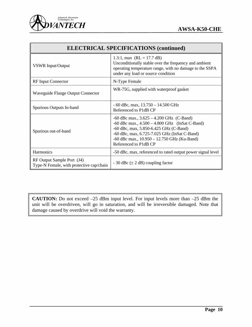
ELECTRICAL SPECIFICATIONS (continued)
VSWR Input/Output
1.3:1, max (RL = 17.7 dB) Unconditionally stable over the frequency and ambient operating temperature range, with no damage to the SSPA under any load or source condition
RF Input Connector N-Type Female
Waveguide Flange Output Connector WR-75G, supplied with waterproof gasket
Spurious Outputs In-band - 60 dBc, max, 13.750 – 14.500 GHz Referenced to P1dB CP
Spurious out-of-band
-60 dBc max., 3.625 – 4.200 GHz (C-Band) -60 dBc max., 4.500 – 4.800 GHz (InSat C-Band) -60 dBc, max, 5.850-6.425 GHz (C-Band) -60 dBc, max, 6.725-7.025 GHz (InSat C-Band) -60 dBc max., 10.950 – 12.750 GHz (Ku-Band) Referenced to P1dB CP
Harmonics -50 dBc, max, referenced to rated output power signal level
RF Output Sample Port (J4) Type-N Female, with protective cap/chain - 30 dBc (± 2 dB) coupling factor
CAUTION: Do not exceed –25 dBm input level. For input levels more than –25 dBm theunit will be overdriven, will go in saturation, and will be irreversible damaged. Note thatdamage caused by overdrive will void the warranty.

AWSA-K50-CHE
Page 11
Figure 1: Product Outline
INPU
T C
UR
RE
NT
INPU
T V
OLT
AG
EG
Hz
V
RE
V.
S/N
BA
ND
P/N
GA
IN
RF
OU
TPU
T P
OW
E R
MFG
Wm
in.
dBm
dB
FRE
QU
EN
CY
A
MO
DEL

AWSA-K50-CHE
Page 12
4. MAJOR SUBSYSTEMS AND THEIR FUNCTIONS The AWSA-K50-CHE is a Ku-band 50W Solid State Power Amplifier (SSPA). The power amplifier is intended for mounting near the hub of the antenna. It incorporates DC main power supply and forced air cooling system, see Figure 1: Product Outline at page 11. The block diagram of the SSPA is shown in Figure 2 at page 13 and various connectors are shown in Figure 3 at page 14. The SSPA features a discrete interface for local or remote monitoring via individual signals as well as interlocking with external devices.
4.1 RF SUBSYSTEM The RF subsystem contains a power amplifier (driver and power module) designed in Solid State Technology, waveguide arm assembly and RF input isolation circuit. The Driver has a gain of 43 dB and an output power (P1dB) of minimum 32 dBm. The Power module has a gain of 27 – 33 dB and an output power (P1dB) of minimum 46 dBm. Current consumption is approximately 50A at 12V. A DC board containing the bias, control and protection circuitry is included in this module. Other functional capabilities are temperature compensation, high temperature shutdown, and reflected power shutdown. The Waveguide Arm Assembly includes a harmonic filter, a three-port output circulator and related power detectors. • The harmonic filter provides a minimum of 65 dB attenuation of all harmonic products other
than the fundamental signal. • The output circulator provides one reflected power port coupled via a detector to the Alarm/
Indicate board for reverse power protection. The output port of the waveguide arm assembly has a minimum 18 dB output return loss and the output flange is WR-75G (grooved).
• One extra sample port, the RF Output Monitor Port, calibrated in coupling ratio versus
frequency, permits the independent monitoring of SSPA output power levels via an ‘N’ type connector, through the use of external spectrum analyzer or portable power meter.
The RF Input Isolation Circuit provides a minimum Input Return Loss of 18 dB over full frequency band at the N-type RF input connector of the SSPA.

AWSA-K50-CHE
Page 13
Figure 2: Block Diagram
ISO
LATO
R
J1 RF
INP
UT
J4O
UTP
UT
MO
NIT
OR
J7W
/G O
UTP
UT
TEM
PE
RA
TUR
ESE
NSO
R
CO
OLI
NG
FAN
+12V
, -9
V
HPA
ASS
EMB
LY
OU
TPU
T W
AVE
GU
IDE
AR
M A
SSEM
BLY
J5 AC LIN
E
+ 12
V
- 9V
- 9V
+ 15
VJ3
DIS
CR
ETE
I/F
COMMON
TEMP ALARM
HIGH TEMP
MUTE
+ 12
V(h
igh
curr
ent)
A B C
TEM
P11
.5 ..
. 60V
SUMMARY ALARM
OVERDRIVE
RESET
+ 12
V
+ 15V
HP
A
ALA
RM
/IND
ICA
TEB
OA
RD
VA
RIF
AN M
AIN
POW
ERSU
PPL
Y
SEC
ON
DA
RY
POW
ERSU
PPL
Y
PO
WE
R C
ON
DIT
ION
ER
BO
AR
D A
SS
EM
BLY
REF
LEC
TED
POW
ERD
ETEC
TOR
30 d
B
30 d
B
OU
TPU
TPO
WER
DET
ECTO
R
FILT
ERIS
OLA
TOR
20 d
B
TEM
PE
RA
TUR
EC
OM
PEN
SAT
ION
DR
UV
ER
DR
IVER
ASS
Y
+12 VPO
WE
RC
ON
DIT
ION
ER
MUTE
AWSA-K50-CHE
Page 14
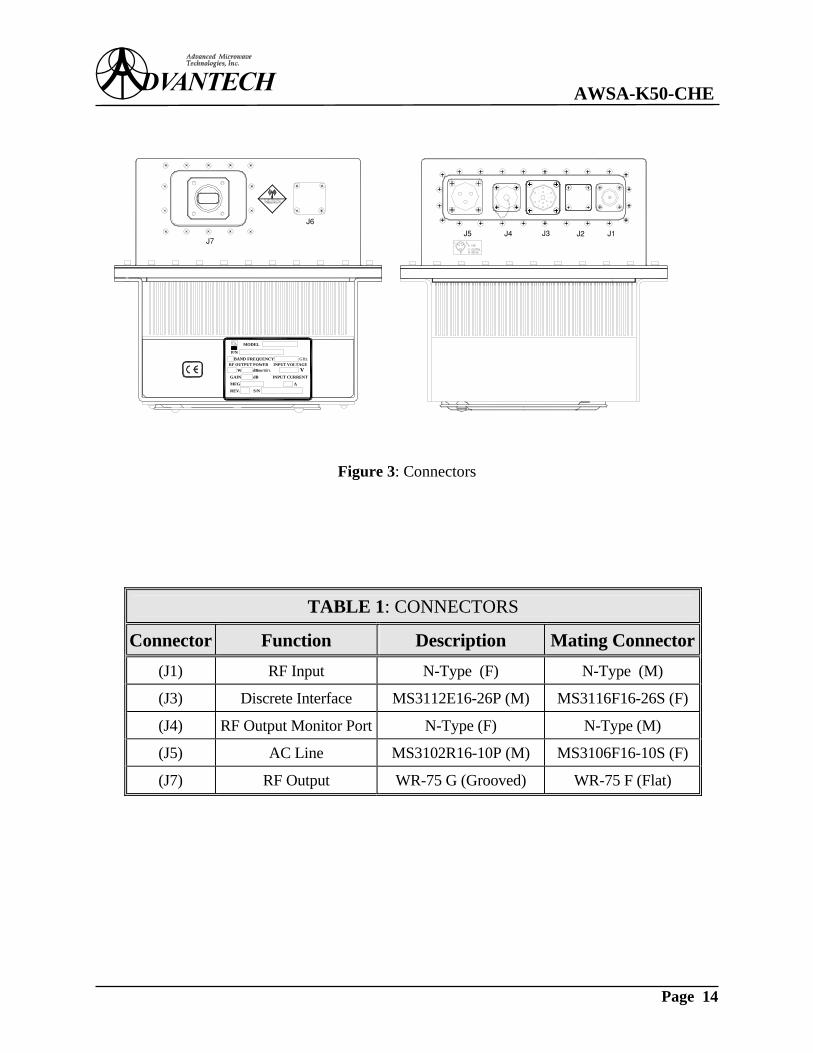
Figure 3: Connectors
TABLE 1: CONNECTORS
Connector Function Description Mating Connector(J1) RF Input N-Type (F) N-Type (M)
(J3) Discrete Interface MS3112E16-26P (M) MS3116F16-26S (F)
(J4) RF Output Monitor Port N-Type (F) N-Type (M)
(J5) AC Line MS3102R16-10P (M) MS3106F16-10S (F)
(J7) RF Output WR-75 G (Grooved) WR-75 F (Flat)
J6
J7J5 J3J4 J2 J1
MFG AS/NREV.
MODEL
RF OUTPUT POWERFREQUENCY
INPUT VOLTAGE
INPUT CURRENTV
GHz
dBdBm min.
GAINW
P/NBAND

AWSA-K50-CHE
Page 15
4.2 POWER SUPPLY SUBSYSTEM The power supply portion of the SSPA provides all of the internal voltages necessary to operate the RF section and the Alarm/Indicate board. The power supply is configured for 90-132 or 180-265 VAC input AC line (auto-ranging). The overall power consumption is 700W typical, at rated RF output power.
TABLE 2: AC LINE (J5) – PINS ASSIGNMENTS
Pin # Description A PHASE (LIVE)
B GROUND
C NEUTRAL
4.3 ALARM/INDICATE BOARD The Alarm/Indicate Board provides: • Status indicator via Form-C relay contacts: FAULT • High Reflected Power shutdown (resulting also in FAULT condition) The Alarm/Indicate board is connected between the microwave power amplifier and the customer interface.
AWSA-K50-CHE
Page 16
5. UNPACKING AND INSTALLATION This section contains instructions for site preparation, unpacking and installation of the SSPA.
5.1 INITIAL INSPECTION Inspect the shipping container for damage. If the container or cushioning material is damaged, immediately contact the carrier that delivered the equipment and submit a damage report. Failure to do so could invalidate future claims.
5.2 UNPACKING Carefully unpack and remove all items (inspect the interior of the container for damage). Save all packing material until all inspections are complete. Verify that all items listed on the packing list have been received. Inspect all items for evidence of damage in shipment. If damage seems evident, immediately contact the carrier that delivered the equipment and file a claim. Failure to do so could invalidate future claims. Check the unit thoroughly for damaged or loose parts. After visual inspection is complete, proceed to the next step.
5.3 INSTALLATION Installation of the SSPA includes four phases:
• Mechanical installation • Electrical installation • RF connections • Cooling considerations
5.3.1 MECHANICAL INSTALLATION This unit is designed for hub-mount (outdoor) applications. Mount the unit using the six mounting holes (0.40”/10 mm.) provided on the power amplifier. Figure 1: Product Outline at page 11 shows the overall mechanical dimensions of the unit.

AWSA-K50-CHE
Page 17
TABLE 3: MECHANICAL SPECIFICATIONS
Physical Dimensions See Figure 1: Product Outline at page 11
Approximate Weight 30 lbs (14 kg)
Mounting holes (6) 0.40” (10 mm) dia. See Figure 1: Product Outline at page 11
5.3.2 ELECTRICAL CONNECTIONS For the locations of the connectors see Figure 1 at page 11 & Figure 3 at page 14. Electrical interconnections to the system consist of prime power (J5) and external connections for discrete interface (J3). Use the provided mating connectors included in the packing kit. • Prime power is applied to (J5) connector located on the front panel of the SSPA via the
connector provided. • Verify that AC power source is turned OFF. • Connect the AC line connector to the AC source (90-132 or 180-265 VAC, 47-63 Hz). Refer
to Figure 3 at page 14 and TABLE 2 at page 15 & TABLE 4 at page 17 for pins assignments and for input voltage level.
• Discrete interface connections are made via (J3) connector. Use the connector provided for
complete monitoring and control of the power amplifier.
TABLE 4: POWER REQUIREMENTS
Power Requirements 90-132 or 180-265 VAC (auto-ranging), 47-63 Hz, single phase
Power Consumption 700 W, typical
WARNING: Proper grounding of the AC power outlet is necessary for personnel andequipment safety.

AWSA-K50-CHE
Page 18
5.3.3 RF CONNECTIONS The following three RF connections are made at the SSPA: • RF input (J1) – Type-N Female provided at the front panel. User needs Type-N male on
interface connection.
• RF output monitor (J4) – Type-N Female, see Figure 3 at page 14. User needs Type-N male
on interface connection. • RF Output (J7) - Waveguide connection WR-75 G (grooved). A waterproof gasket is
provided in the shipping kit. To install the waveguide output flange, proceed as follows: 1. Install the waterproof gasket (supplied) at the output flange of the SSPA. 2. Position the interconnecting flange so that it aligns precisely with the waveguide flange at
(J7). 3. After alignment is verified, loosely attach the interconnecting waveguide to the output
waveguide flange of the SSPA. Start all bolts (supplied) and verify proper alignment before uniformly tightening the bolts.
4. Carefully tighten all bolts (in opposite pairs rather than sequentially around the perimeter of
the flange) so that the connection is firm. Do not over-tighten because this can strip the threads or distort the mating flange. Recommended torque is 15 in-lbs for #6-32 bolts.
NOTE: Wrap the mastic tape (provided in the shipping kit) around all connectors in order toprevent water/humidity ingress and resultant damage. Squeeze the tape tightly and ensure thatboth ends of the tape have formed around the connector and the cable.
CAUTION: Beware of destructive Pin Depth of Mating Connector. When an RF component connector is mated with a connector having a destructive pin depth, damage willusually occur to the RF component connector. A destructive pin depth is one that is too longin respect to the reference plane of the connector. The center pin of the connectors used byADVANTECH has a precision tolerance measured in mils (1/1000 inch). The matingconnectors of various suppliers may not be precision types. Consequently, the center pins ofthese devices may not have the proper depth.

AWSA-K50-CHE
Page 19
5.3.4 COOLING CONSIDERATIONS The SSPA is cooled by forced air. The cooling fan is configured for 48V DC operation. Depending on environmental conditions, the air inlet or outlet openings may become obstructed by debris, reducing the efficiency of the cooling system. Inspect the unit periodically to ensure that the grill of the fan intake and all openings on the unit are free of any obstructions. Insufficient cooling will significantly impact SSPA longevity.
TABLE 5: ENVIRONMENTAL CONDITIONS
Temperature:
Non-operating (continuous exposure)
Operating (ambient)
- 60°C to + 85°C
- 30°C to + 55°C
Relative Humidity: 100% condensing
Altitude: 10,000 feet AMSL, derated 2°C/1,000 feet from AMSL
NOTE: The rotation speed of the cooling fan is temperature dependent.
AWSA-K50-CHE
Page 20
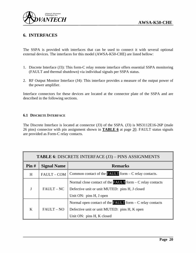
6. INTERFACES The SSPA is provided with interfaces that can be used to connect it with several optional external devices. The interfaces for this model (AWSA-K50-CHE) are listed bellow: 1. Discrete Interface (J3): This form-C relay remote interface offers essential SSPA monitoring
(FAULT and thermal shutdown) via individual signals per SSPA status. 2. RF Output Monitor Interface (J4): This interface provides a measure of the output power of
the power amplifier. Interface connectors for these devices are located at the connector plate of the SSPA and are described in the following sections.
6.1 DISCRETE INTERFACE The Discrete Interface is located at connector (J3) of the SSPA. (J3) is MS3112E16-26P (male 26 pins) connector with pin assignment shown in TABLE 6 at page 20. FAULT status signals are provided as Form-C relay contacts.
TABLE 6: DISCRETE INTERFACE (J3) – PINS ASSIGNMENTS
Pin # Signal Name Remarks
H FAULT – COM Common contact of the FAULT form – C relay contacts.
J FAULT – NC
Normal close contact of the FAULT form – C relay contacts
Defective unit or unit MUTED: pins H, J closed
Unit ON: pins H, J open
K FAULT – NO
Normal open contact of the FAULT form – C relay contacts
Defective unit or unit MUTED: pins H, K open
Unit ON: pins H, K closed

AWSA-K50-CHE
Page 21
6.1.1 FUNCTIONAL DESCRIPTION The Discrete Interface is connected to the Alarm/Indicate Board and continuously (in the normal condition) monitors the status of the SSPA: If: • the power amplifier is ON • there are no problems in the power amplifier • the power amplifier is not muted, the FAULT relay is energized. If: • one or more GaAs FET’s failed, or • the power amplifier is muted, a Summary Alarm signal will be internally generated and consequently detected by the Alarm/Indicate Board; by receiving this signal, the FAULT relay is de-energized, its normal close contact being connected to its common terminal. This will indicate a FAULT condition on the customer interface. The Alarm/Indicate board receives an output VSWR signal from the reflected power sensor. The power amplifier will be muted when the input voltage is above the threshold level (with 1 sec. delay). Also, the power amplifier will declare the FAULT condition because it will be in a shutdown state. Power-up returns unit to active condition if the power amplifier is in the normal condition. The threshold level is set for VSWR of 3:1, max. (6 dB back off from rated power).
6.2 RF OUTPUT MONITOR PORT This RF interface is located at (J4) connector, of SSPA. It is typically used for independent monitoring of SSPA output power levels through the use of an external power meter. To determine the true output power in dBm, add the value measured at the RF Output Monitor Port (J4) to the calibrated coupling factor corresponding to the specific frequency. A table of coupling factor versus frequency can be found in the Test Data Sheet provided with each SSPA.
WARNING: Prolonged operation without a load at the output may cause severe bodily harm,loss of sight, even death. Do not operate any power amplifier if the RF output is not connectedto a load.
AWSA-K50-CHE
Page 22
7. INITIAL POWER ON AND CHECKOUT This section describes the procedure for turning on the SSPA for the first time. It also describes the steps for initial checkout of the system. Before proceeding with the steps in this section, read it completely, to become familiar with normal operation of the SSPA.
7.1 PRE-POWER PROCEDURES Before applying prime power to the SSPA, verify that the following conditions are met:
• The voltages of the station’s AC prime power matches those marked on the ID label, which is 90-132 or 180-265 VAC (auto-ranging) for this unit.
• The prime power station is properly grounded. • All connections are tight, no wires are pinched, and no other hardware has been loosened
during handling.
• The main power switch on the prime power station is turned OFF. • The RF Input and RF Output are connected to a matched source and a proper load
capable to withstand full CW RF power, see Electrical Specifications.
• The cooling fan is not obstructed.
WARNING: The information presented in this section is addressed to technicians who havespecific training in, and knowledge of Microwave Power Transmitters. Inappropriate use ofthe SSB can cause harm to the operator or equipment. Do not attempt the procedures outlinedin this section before becoming thoroughly familiar with its contents.
CAUTION: Failure to verify these pre-power conditions may damage the power amplifier orcause it to malfunction. Operating the power amplifier before verifying these items may alsovoid the warranty.
CAUTION: Do not exceed –25 dBm input level. For input levels more than –25 dBm theunit will be overdriven, will go in saturation, and will be irreversible damaged. Note thatdamage caused by overdrive will void the warranty.

AWSA-K50-CHE
Page 23
8. OPERATION This section describes the normal operation of the SSPA. The SSPA features an integrated Alarm/Indicate Board that accepts control input and provides SSPA status and metering. The design of this equipment allows minimum operator intervention and maintenance.
8.1 ESSENTIAL OPERATING PROCEDURES Perform the SSPA’s normal operating procedure in the following order. 1. Be sure that the ‘Initial Power On and Checkout’ procedures described in Section 7 at page
22 have been performed. 2. Switch ON the main power supply. 3. Verify that no fault message is active on the Discrete Interface. 4. Ensure that the RF input is being applied to the SSPA.
5. Confirm that the RF output power has been set to the desired level. To check the output
power level if direct measurement is not possible, connect a separate power meter (not supplied) to the Type ‘N’ output monitor port (J4), noting the calibration table in the Test Data Sheets.
The SSPA may need a 30 minutes warm up in order to meet all Electrical Specifications. In case of use of a pressurized output waveguide system, it is mandatory to install a pressure window in order to protect the power amplifier from high pressure.
CAUTION: Do not exceed –25 dBm input level. For input levels more than –25 dBm theunit will be overdriven, will go in saturation, and will be irreversible damaged. Note thatdamage caused by overdrive will void the warranty.

AWSA-K50-CHE
Page 24
9. MAINTENANCE This section describes scheduled maintenance procedure for SSPA.
9.1 PREVENTIVE MAINTENANCE This product requires minimum maintenance. This consists of visual inspection and cleaning.
9.1.1 MECHANICAL PREVENTIVE MAINTENANCE Mechanical preventive maintenance consists of verifying all mechanical parts. Most of them are performed with the AC power switched off. Perform the following inspection: 1. With the AC power disconnected or switched off, check that all connectors and plugs are
properly seated in their mating connectors and have not been damaged. Replace any bad connector plugs and re-seat any that are dislodged.
2. Inspect electrical wiring for signs of discolored, broken or bad insulation. Repair or replace
as needed. 3. Inspects all waveguides for discoloration, cracks, loose connectors and improper sealing.
Tighten or replace waveguides as required. 4. Check for other defects. These include, but are not limited to, wear, breakage, deterioration,
fungus, excess moisture and mounting integrity.
9.1.2 CHECKING THE COOLING FAN The cooling fan is located at the bottom shroud of the SSPA. Verify that the fan is operating smoothly. Any suspect noise may indicate wear and fan will have to be replaced. Check for debris or dust in the fan intake and in all openings on the unit. This may reduce the efficiency of the cooling system. The fan should be replaced every two years, in order to ensure the proper cooling of the unit.
CAUTION: Improper maintenance of the SSB may void the warranty.
WARNING: The person performing maintenance of this equipment must have training andknowledge of both the product and safety requirements and safety issues related to the equipment. Read and practice the safety guidelines at the beginning of this manual (Section 2at page 6).
WARNING: Do not come in contact with any electrical assembly while power is applied.
AWSA-K50-CHE
Page 25
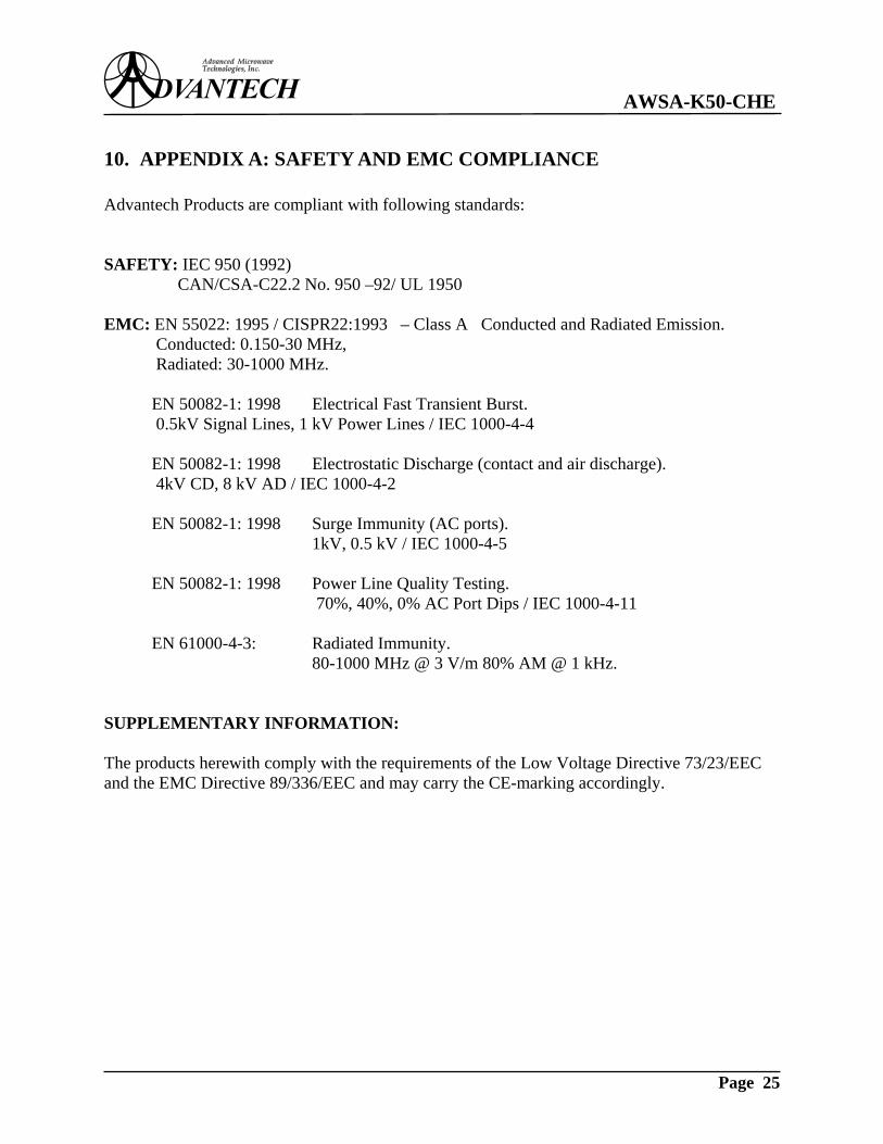
10. APPENDIX A: SAFETY AND EMC COMPLIANCE Advantech Products are compliant with following standards: SAFETY: IEC 950 (1992) CAN/CSA-C22.2 No. 950 –92/ UL 1950 EMC: EN 55022: 1995 / CISPR22:1993 – Class A Conducted and Radiated Emission.
Conducted: 0.150-30 MHz, Radiated: 30-1000 MHz.
EN 50082-1: 1998 Electrical Fast Transient Burst.
0.5kV Signal Lines, 1 kV Power Lines / IEC 1000-4-4 EN 50082-1: 1998 Electrostatic Discharge (contact and air discharge).
4kV CD, 8 kV AD / IEC 1000-4-2 EN 50082-1: 1998 Surge Immunity (AC ports). 1kV, 0.5 kV / IEC 1000-4-5 EN 50082-1: 1998 Power Line Quality Testing. 70%, 40%, 0% AC Port Dips / IEC 1000-4-11 EN 61000-4-3: Radiated Immunity. 80-1000 MHz @ 3 V/m 80% AM @ 1 kHz. SUPPLEMENTARY INFORMATION: The products herewith comply with the requirements of the Low Voltage Directive 73/23/EEC and the EMC Directive 89/336/EEC and may carry the CE-marking accordingly.