5.1: introduction to pulse modulation
TRANSCRIPT

Chapter Five Pulse Modulation
1
5.1: Introduction to Pulse Modulation
In pulse modulation some parameter of a pulse train is varied in accordance
with the massage signal.
Analog pulse modulation is classified as
Pulse Amplitude Modulation (PAM)
Pulse Width Modulation (PWM)
Pulse Position Modulation (PPM)
Digital modulation is classified as
Pulse Code Modulation
Delta Modulation
5.2: Pulse Amplitude Modulation (PAM)
PAM is an analog modulating scheme in which the amplitude of the pulse
carrier varies proportional to the instantaneous amplitude of the message
signal.
Fig 1: Pulse Amplitude Modulation

Chapter Five Pulse Modulation
2
There are two types of sampling techniques for transmitting a signal using
PAM. They are:
1. Flat Top PAM
2. Natural PAM
Flat Top PAM: The amplitude of each pulse is directly proportional to
modulating signal amplitude at the time of pulse occurrence. The amplitude
of the signal cannot be changed with respect to the analog signal to be
sampled. The tops of the amplitude remain flat.
Fig.2: Flat Top PAM
Natural PAM: The amplitude of each pulse is directly proportional to
modulating signal amplitude at the time of pulse occurrence. Then follows
the amplitude of the pulse for the rest of the half cycle.
Fig.3: Natural PAM
Chapter Five Pulse Modulation
3
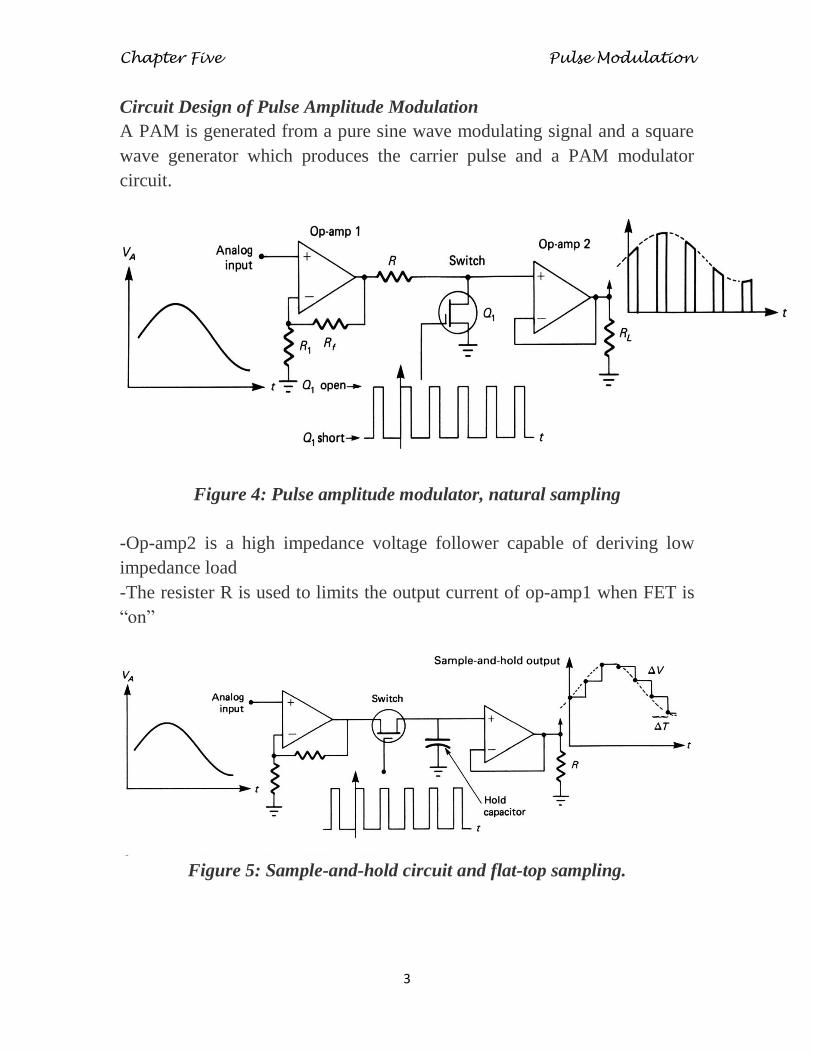
Circuit Design of Pulse Amplitude Modulation
A PAM is generated from a pure sine wave modulating signal and a square
wave generator which produces the carrier pulse and a PAM modulator
circuit.
Figure 4: Pulse amplitude modulator, natural sampling
-Op-amp2 is a high impedance voltage follower capable of deriving low
impedance load
-The resister R is used to limits the output current of op-amp1 when FET is
“on”
Figure 5: Sample-and-hold circuit and flat-top sampling.

Chapter Five Pulse Modulation
4
Demodulation of PAM
For demodulation of PAM signal, the PAM signal is fed to the low pass
filter. The low pass filter eliminates the high-frequency ripples and generates
the demodulated signal. This signal is then applied to the inverting amplifier
to amplify its signal level to have the demodulated output with almost equal
amplitude with the modulating signal.
Figure.6: PAM Demodulation
fo for the LPF must within the range of fm < fo < fs - fm
Applications of PAM
It is used in Ethernet communication.
It is used in many micro-controllers for generating the control signals.
It is used in Photo-biology.
It is used as an electronic driver for LED lighting.
Advantages
It is the simple process for both modulation and demodulation.
Transmitter and receiver circuits are simple and easy to construct.
PAM can generate other pulse modulation signals and can carry the
message at the same time.
Disadvantages
Bandwidth should be large for transmission PAM modulation.
Noise will be great.
Pulse amplitude signal varies so power required for transmission will be
more.

Chapter Five Pulse Modulation
5
5.2: Pulse Width Modulation
Pulse Width Modulation (PWM) or Pulse Duration Modulation
(PDM) or Pulse Time Modulation (PTM) is an analog modulating scheme
in which the duration or width or time of the pulse carrier varies
proportional to the instantaneous amplitude of the message signal.
The width of the pulse varies in this method, but the amplitude of the signal
remains constant. Amplitude limiters are used to make the amplitude of the
signal constant. These circuits clip off the amplitude, to a desired level and
hence the noise is limited.
Modulation of PWM:
Figure 7, shows a PWM modulator. This circuit is simply a high-gain
comparator that is switched on and off by the sawtooth waveform
derived from a very stable-frequency oscillator.
Notice that the output will go to +Vcc if the analog signal exceeds the
sawtooth voltage.
The output will go to -Vcc if the analog signal is less than the sawtooth
voltage.
Figure 7. Pulse width modulator.
Chapter Five Pulse Modulation
6
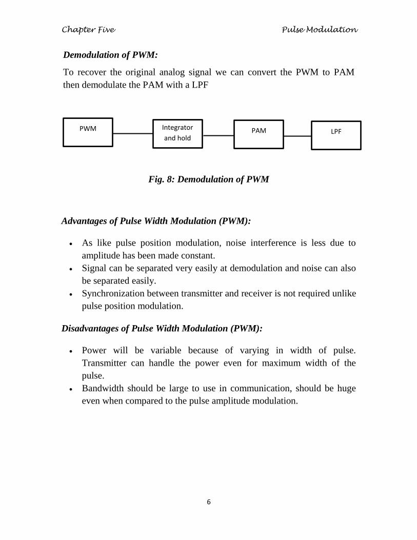
Demodulation of PWM:
To recover the original analog signal we can convert the PWM to PAM
then demodulate the PAM with a LPF
Fig. 8: Demodulation of PWM
Advantages of Pulse Width Modulation (PWM):
As like pulse position modulation, noise interference is less due to
amplitude has been made constant.
Signal can be separated very easily at demodulation and noise can also
be separated easily.
Synchronization between transmitter and receiver is not required unlike
pulse position modulation.
Disadvantages of Pulse Width Modulation (PWM):
Power will be variable because of varying in width of pulse.
Transmitter can handle the power even for maximum width of the
pulse.
Bandwidth should be large to use in communication, should be huge
even when compared to the pulse amplitude modulation.
PWM Integrator
and hold PAM LPF

Chapter Five Pulse Modulation
7
Applications of Pulse Width Modulation (PWM):
PWM is used in telecommunication systems.
PWM can be used to control the amount of power delivered to a load
without incurring the losses. So, this can be used in power delivering
systems.
Audio effects and amplifications purposes also used.
PWM signals are used to control the speed of the robot by controlling
the motors.
PWM is also used in robotics.
Embedded applications.
Analog and digital applications etc
5.3: Pulse Position Modulation
Pulse Position Modulation (PPM) is an analog modulating scheme in
which the amplitude and width of the pulses are kept constant, while the
position of each pulse, with reference to the position of a reference pulse
varies according to the instantaneous sampled value of the message signal.
The transmitter has to send synchronizing pulses (or simply sync pulses) to
keep the transmitter and receiver in synchronism. These sync pulses help
maintain the position of the pulses. The following figures explain the Pulse
Position Modulation.
Chapter Five Pulse Modulation
8
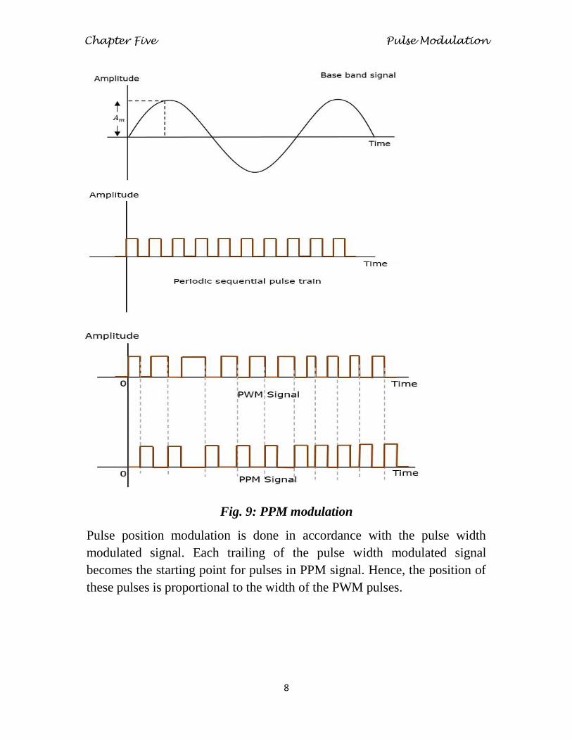
Fig. 9: PPM modulation
Pulse position modulation is done in accordance with the pulse width
modulated signal. Each trailing of the pulse width modulated signal
becomes the starting point for pulses in PPM signal. Hence, the position of
these pulses is proportional to the width of the PWM pulses.

Chapter Five Pulse Modulation
9
Modulation of PPM:
Fig.10 : Modulation of PWM and PPM

Chapter Five Pulse Modulation
10
Demodulation of PPM:
Figure 11: PPM demodulator.
This is achieved by full-wave rectifying the PPM pulses of Figure 11,
which has the effect of reversing the polarity of the negative (clock-
rate) pulses.
Then an edge-triggered flipflop (J-K or D-type) can be used to
accomplish the same function as the RS flip-flop of Figure 11, using
the clock input.
The penalty is: more pulses/second will require greater bandwidth,
and the pulse width limit the pulse deviations for a given pulse period.

Chapter Five Pulse Modulation
11
Advantages of Pulse Position Modulation (PPM):
Pulse position modulation has low noise interference when compared
to PAM because amplitude and width of the pulses are made constant
during modulation.
Noise removal and separation is very easy in pulse position
modulation.
Power usage is also very low when compared to other modulations due
to constant pulse amplitude and width.
Disadvantages of Pulse Position Modulation (PPM):
The synchronization between transmitter and receiver is required,
which is not possible for every time and we need dedicated channel for
it.
Large bandwidth is required for transmission same as pulse amplitude
modulation.
Special equipments are required in this type of modulations.

Chapter Five Pulse Modulation
12
Applications of Pulse Position Modulation (PPM):
Used in non coherent detection where a receiver does not need any
Phase lock loop for tracking the phase of the carrier.
Used in radio frequency (RF) communication.
Also used in contactless smart card, high frequency, RFID (radio
frequency ID) tags and etc.
5.4: Comparison between PAM, PWM, and PPM
The comparison between the above modulation processes is presented in a
single table.
PAM PWM PPM
Amplitude is varied Width is varied Position is varied
Bandwidth depends on
the width of the pulse
Bandwidth depends on
the rise time of the pulse
Bandwidth depends on
the rise time of the pulse
Instantaneous
transmitter power
varies with the
amplitude of the pulses
Instantaneous transmitter
power varies with the
amplitude and width of
the pulses
Instantaneous
transmitter power
remains constant with
the width of the pulses
System complexity is
high
System complexity is
low
System complexity is
low
Noise interference is
high Noise interference is low
Noise interference is
low
It is similar to
amplitude modulation
It is similar to frequency
modulation
It is similar to phase
modulation