51351 - titan series truck scale 6020 series installation ... · truck scale 6020 series...
TRANSCRIPT
51351 . Revision 4 10/2016
© 2015-2016 by Fairbanks Scales, Inc.
All rights reserved
Titan Series
Truck Scale
6020 Series
Installation Manual
Service Manual
Service Manual
Service Manual


Disclaimer Every effort has been made to provide complete and accurate information in this manual. However, although this manual may include a specifically identified warranty notice for the product, Fairbanks Scale makes no representations or warranties with respect to the contents of this manual, and reserves the right to make changes to this manual without notice when and as improvements are made. Fairbanks Scale shall not be liable for any loss, damage, cost of repairs, incidental or consequential damages of any kind, whether or not based on express or implied warranty, contract, negligence, or strict liability arising in connection with the design, development, installation, or use of the scale.
© Copyright 2016
This document contains proprietary information protected by copyright. All rights are reserved; no part of this manual may be reproduced, copied, translated or transmitted in any form or by any means without prior written permission of the manufacturer

10/16 4 Rev. 4 51351
AMENDMENT RECORD
Titan Series Motor Truck Scale
6020 Series
Installation Manual Document 51351
Manufactured by
Fairbanks Scales 821 Locust Kansas City, MO 64106
Created 10/14
Revision 1 11/14 New product documentation release.
Revision 2 03/15 Updated Parts
Revision 3 01/16 Updated Parts > Load Cells & Associated Hardware
Revision 4 10/16 Maintenance > Scale maintenance updates, Parts
10/16 5 Rev. 4 51351
TABLE OF CONTENTS SECTION 1: GENERAL INFORMATION ................................................................... 6
1.1. Introduction ............................................................................................................ 6 1.1.1. Specifications .................................................................................................... 6 1.1.2. Scale Description ............................................................................................... 7
1.2. Users’ Responsibility ............................................................................................ 8
SECTION 2: SCALE INSTALLATION ........................................................................ 9
2.1. Introduction ............................................................................................................ 9
2.2. Checklist of Tools, Equipment, and Materials ..................................................... 9
2.3. Installation Safety Policy .................................................................................... 10
2.4. Standard Foundation Installation ....................................................................... 11 2.4.1. Preparing the Modules ..................................................................................... 12 2.4.2. Setting the Center Module ............................................................................... 12 2.4.3. Setting End Modules ........................................................................................ 13 2.4.4. Connecting the Modules .................................................................................. 14 2.4.5. Checking Adjustment ....................................................................................... 14 2.4.6. Base Plate Completion .................................................................................... 15 2.4.7. Installing Load Cells ......................................................................................... 16 2.4.8. Load Cell Cables ............................................................................................. 17 2.4.9. Final Checking Adjustment .............................................................................. 17
SECTION 3: ELECTRICAL INSTALLATION ........................................................... 18
3.1. Installation ............................................................................................................ 18 3.1.1. Boxes .............................................................................................................. 18 3.1.2. Wiring .............................................................................................................. 18 3.1.3. Smart Sectional Controller (SSC)..................................................................... 19 3.1.4. Preventing Moisture Entry ................................................................................ 19 3.1.5. SCC Wiring ...................................................................................................... 19
3.2. Wiring SSCs and PPSs for Intalogix Systems ................................................... 20 3.2.1. Cell Numbering ................................................................................................ 20 3.2.2. Grounding ........................................................................................................ 20 3.2.3. Indicator-to-PPS Cable Connection ................................................................. 21
SECTION 4: MAINTENANCE ................................................................................... 22
4.1. Scale Maintenance ............................................................................................... 22
4.2. Mechanical Faults ................................................................................................ 22
4.3. RC Load Cell Replacement ................................................................................. 22
SECTION 5: PARTS ................................................................................................. 24
5.1. Load Cells and Associated Hardware ................................................................ 24
5.2. Other Scale Hardware .......................................................................................... 24
SECTION 6: ACCESSORIES ................................................................................... 25
6.1. Accessories .......................................................................................................... 25
6.2. Field Installed Rub Rails ...................................................................................... 25
APPENDIX I: FOUNDATION CHECK LIST ............................................................. 27
APPENDIX II: SCALE CONNECTIONS ................................................................... 29
APPENDIX III: SCALE DIMENSIONS ...................................................................... 30

10/16 6 Rev. 4 51351
SECTION 1: GENERAL INFORMATION
1.1. Introduction
This Instruction manual provides installation instructions for the Fairbanks Titan Modular Steel Deck Truck Scales.
For correct Titan Scale installation, use these tools.
See Appendix I in Methods and Procedures FF-2267 / 101732.
The Certified Prints and Setting Plans supplied with the scale.
This Instruction Manual, 51351.
The concrete foundation work must be performed according to the Certified Prints issued for the specific customer and order number.
– The name and order number for the particular customer will be on the prints.
1.1.1. Specifications
Load Cell Specifications
Height 4 -11/16”
Capacity 110K lbs (50t)
Type Rocker Column
Sealing Complete hermetic sealing; cable entry sealed by glass to metal header
Material Stainless Steel
17-4 PH (1.3448)
Rating IP68 (NEMA 6P)
Resistance 1,000 Ohms
Operating Temperature -40 to +80C (-40 to 176F)
Output 2.0 mv/v
Combined Error ≤0.02%
Zero Balance (FSO) 1.0%
Excitation 5 to 15 VDC
Ultimate Overload 300%
Cable Length 15’
Cable Protection Stainless Steel Sheathing
Approvals NTEP COC# 14-024 Factory Mutual Approved

Section 1: General Information
10/16 7 Rev. 4 51351
1.1.1. Specifications, continued
Scale Specifications
Deck Dimensions Lengths: 27’, 30’, 35’, 60’, 70’, 80’, 90’, 105’
Widths: 10’, 11’, 12’, 14’
CLC/DTAC 120K lbs
Gross Capacities 150K to 300K lbs
Sections 2 to 4
Modules 1 to 3
Module Design Orthotropic
Module Construction USA Structural Steel
Module Under Structure Open Bottom
Deck Plate Thickness 3/8”
Approval NTEP COC#: 96-089
MC# AM-4949
1.1.2. Scale Description
The TITAN Modular Steel Deck Truck Scales are available in various lengths from twenty-seven to one hundred and five feet (27’ – 105’), and widths from ten to fourteen feet (10’ – 14’).
– The scale is made up of modules of 27, 30, and 35 feet lengths.
– All modules are assembled and welded at the factory.
Locate the scale so that trucks can approach and exit easily.
– Smooth and level approaches are required at each end of the platform to reduce loading shock and facilitate scale testing.
– Approaches must conform to the requirements of the law in the state in which the scale is being installed.
▪ In the absence of such laws, the approaches must conform to Paragraph UR.2.6 National Institute of Standards and Technology Handbook 44.
▪ The first ten feet (10’) must be level and on the same plane as the scale platform.
– The platform should be visible from the instrument location.
– It must be built so surface water will drain easily, and not collect under the scale.

Section 1: General Information
10/16 8 Rev. 4 51351
1.2. Users’ Responsibility
All electronic and mechanical calibrations and/or adjustments required for making this equipment perform to accuracy and operational specifications should be performed by trained service personnel.
Absolutely no physical, electrical or program modifications other than selection of standard options and accessories are to be made to this equipment.
Electrical connections other than those specified may not be performed, and physical alterations (holes, etc.) are not allowed.
Please call your local
FAIRBANKS SCALES REPRESENTATIVE for any question or problems.

10/16 9 Rev. 4 51351
SECTION 2: SCALE INSTALLATION
2.1. Introduction
Standard installation consists of these steps.
A. Foundation check, layout, and base plate setting.
B. Tools, materials, documentation, and a crane.
C. Setting the modules.
D. Setting the modules on load cells.
2.2. Checklist of Tools, Equipment, and Materials
Certified Prints.
Mobile Crane of sufficient capacity to safely lift and place the weigh bridge modules.*
Four (4) equal length lifting chains/cables with hooks.*
Listed below are the approximate maximum weights of scale modules.
– Steel Deck Modules – 8 tons.
– Field Pour Modules – 22.5 tons.
▪ With Concrete – 12.5 to 15 tons (+/- 5%).
Machinists Levels (Starrett # 134 & 132-6).
Hand Tools.
Hammer Drill with 5/8" Bit, 16" long.
16 ton hydraulic jacks (2).
100' Steel Tape Measure.
String-line and chalk-line.
Pry-bars.
High quality grease and anti-seize.
Load Cell Locating Tools – 157069 for 4 11/16” cells (one per load cell).
* IMPORTANT NOTE: Request the Mobile Crane and Chains in advance from the
crane vendor.
Section 2: Scale Installation
10/16 10 Rev. 4 51351
2.3. Installation Safety Policy
Prior to installation, always verify that the equipment satisfies the customer's requirements as supplied, and as described in this manual.
If the equipment cannot satisfy the application and the application cannot be modified to meet the design parameters of the equipment, the installation should NOT be attempted.
Instructions within this manual apply to the instrument and its specific accessories. Installation procedures for printers and other peripherals are given in manuals specifically provided for those units. The instructions include a pre-installation checkout which must be performed either at the service center before the technician goes to the site, or at the site before he places the equipment in service.
All electronic and mechanical calibrations and/or adjustments required to make this equipment perform to accuracy and operational specifications are considered to be part of the installation, and are included in the installation charge. Only those charges which are incurred as a result of the equipment's inability to be adjusted or calibrated to performance specifications may be charged to warranty.
Absolutely no physical, electrical, or program modifications other than selection of standard options and accessories are to be made to this equipment. Electrical connections other than those specified may not be performed, and no physical alterations (mounting holes, etc.) are allowed and will immediately void warranty
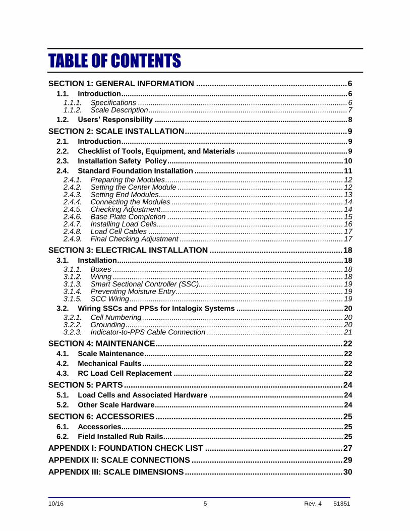
All load cells, load cell cables, and all interconnecting cables used for the scale components must be located a minimum of thirty-six inches (36”) away from all single and multiple phase high energy circuits and electric current-carrying conductors.
This includes, but is not limited to digital weight instruments, junction boxes, sectional controllers, and power supplies.
This includes any peripheral devices, such as printers, remote displays, relay boxes, remote terminals, card readers, and auxiliary data entry devices.
Scale components themselves must also be at least thirty-six inches (36”) away from other high energy components, including the following devices.
Any machinery with outputs of 120, 240, or 480 VAC.
High voltage wiring runs and stations, AC power transformers, overhead or buried cables, electric distribution panels, electric motors, florescent and high intensity lighting which utilize ballast assemblies, electric heating equipment, traffic light wiring and power, and all relay boxes.
Scale components are not designed to operate on internal combustion engine driven electric generators and other similar equipment.
– This includes all digital weight Instruments and peripheral devices.
Electric arc welding can severely damage scale components, such as digital weight Instruments, junction boxes, sectional controllers, power supplies, and load cells.
The Service Technician’s responsibility that all personnel are fully trained and familiar with the equipment's capabilities and limitations before the installation is considered complete.

Section 2: Scale Installation
10/16 11 Rev. 4 51351
2.4. Standard Foundation Installation
Noted below are the steps to a standard foundation installation.
1. Before installing any part of the scale, check the foundation for accuracy using Foundation Inspection.
– Field Check List, FF-2267 / 101732.
– See Appendix I: Foundation Checklist.
2. Layout and position the base plates in the proper locations using the Methods & Procedures and Certified prints.
– Each base plate must be level and in full contact with the top of the pier.
– Adjustments can be made by chipping the concrete or grouting under the base plates.
3. Re-check the locations of each base plate against the Certified prints.
4. Insert four (4) 3/8" roll pins into each baseplate to retain the cup.
5. Put a 3/16" shim on the Baseplate between the Retaining Pins and under the Lower Cup.
a. The Lower Cups for the load cells have a pin which should be aligned inward, towards the center line of the scale.
▪ This leaves the load cell cable exiting the load cell to the inside.
▪ It is not necessary to install base plate anchors at this time.
6. Place the upper cup on the edge of the upper foundation next to each base plate.
7. Place the Load Cell Locating Tool next to each Base Plate.
Section 2: Scale Installation
10/16 12 Rev. 4 51351
2.4.1. Preparing the Modules
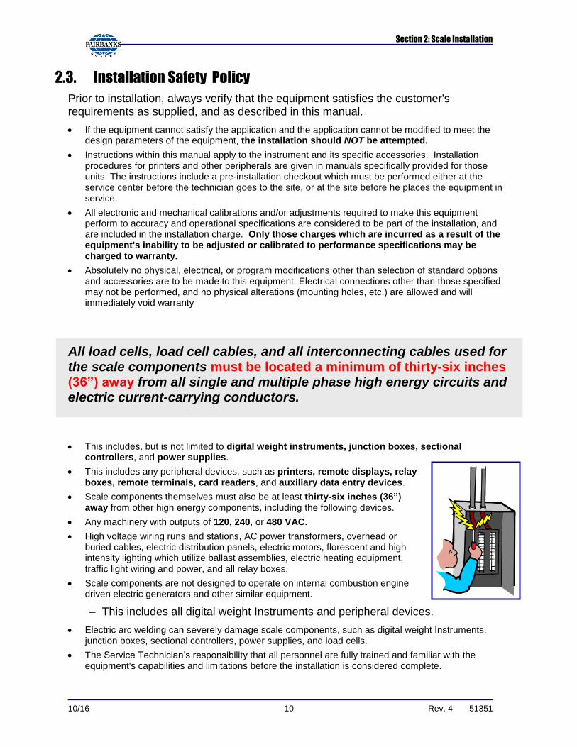
1. Prepare the modules for lifting.
– The modules are complete with lifting channels welded to the sides for attaching lifting hooks.
– No lifting bolts are required.
2.4.2. Setting the Center Module
1. Always set the center module into place first.
– The center module has four (4) load cells to install, all other modules will have two (2) load cells.
– The modules must be placed in the proper order and aligned in the foundation so that all modules fit correctly.
2. Place blocks that will set the modules at a height slightly less than the finished height as safety blocks, or for setting the modules on.
3. Lift the center module to a location above the four center load cell base plates.
OPTION 1
a. Set the module directly on the locating tools and the blocks will act as safety stands.
b. Install a Load Cell Bearing Cup into the upper receiver of each corner, grease will help hold the cup in place.
c. Insert the upper end of the locating tool over the upper cup on the module.
d. Lower the module while holding the locating tool upright and guiding the bottom of the tool into the lower cup.
e. When the center module is set on all four locating tools, keep tension on the cables until the module is centered and straight.
f. Use hydraulic jacks to lift the unit slightly and shift the base plates to get the locating tools plumb and the bottom flange FLUSH with the side of the cup.

Section 2: Scale Installation
10/16 13 Rev. 4 51351
2.4.2. Setting the Center Module, Continued
OPTION 2
a. Set the modules on the blocks first, then onto the locating tools.
▪ When the module is set on the blocks, keep tension on the cables until the module is properly aligned.
▪ Use hydraulic jacks to lift the unit slightly then install the locating tools.
b. Shift the base plates to get the tools plumb.
c. Measure from each side of each end of the module, to the end walls, to be certain the module is plumb and square before removing tension.
d. Once the tension on the lift cables is released, remove the lift cables.
2.4.3. Setting End Modules
1. Guide the modules into place with the supporting blocks on the end of the module coming to rest on the supporting blocks of the center module.
2. Lower the other end of the module onto the load cell locating tools or blocks (see below).
3. Before releasing tension on the cables, check the alignment of the end modules to the center module and to the end wall.
4. Use the shims provided to set height and fill any gaps on the supporting blocks to get the modules aligned.
Section 2: Scale Installation
10/16 14 Rev. 4 51351
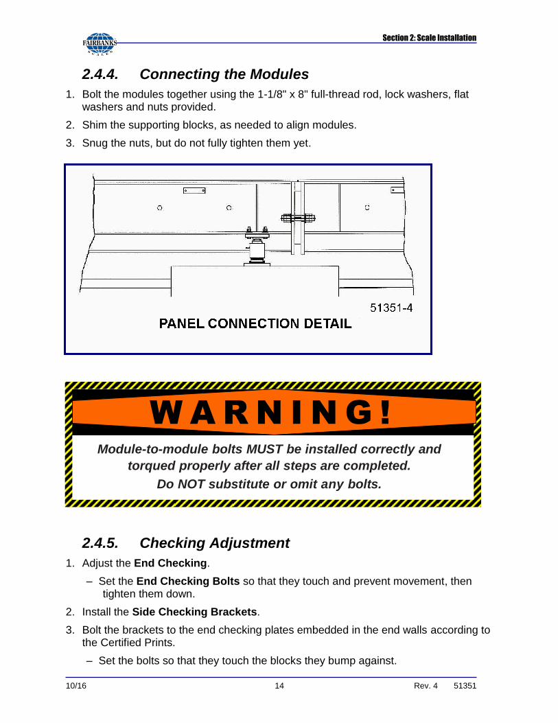
2.4.4. Connecting the Modules
1. Bolt the modules together using the 1-1/8" x 8" full-thread rod, lock washers, flat washers and nuts provided.
2. Shim the supporting blocks, as needed to align modules.
3. Snug the nuts, but do not fully tighten them yet.
2.4.5. Checking Adjustment
1. Adjust the End Checking.
– Set the End Checking Bolts so that they touch and prevent movement, then tighten them down.
2. Install the Side Checking Brackets.
3. Bolt the brackets to the end checking plates embedded in the end walls according to the Certified Prints.
– Set the bolts so that they touch the blocks they bump against.
Module-to-module bolts MUST be installed correctly and
torqued properly after all steps are completed.
Do NOT substitute or omit any bolts.
W A R N I N G !

Section 2: Scale Installation
10/16 15 Rev. 4 51351
2.4.6. Base Plate Completion
1. Check that all locating tools are properly aligned.
2. Drill the holes for the outside base plate anchors using a hammer drill and the 5/8" drill bit.
3. Tap the anchors into clean holes and tighten the nuts securely.
Section 2: Scale Installation
10/16 16 Rev. 4 51351
2.4.7. Installing Load Cells
1. Unpack the load cells and mark each calibration certificate with the load cell location and position.
2. Bolt the Anti-Rotation Clip onto the side of the Load Cell.
3. Starting at one end of the assembled platform, place hydraulic jacks at the corners so the section can be lifted off the locating tool.
– Two (2) hydraulic jacks may be required.
4. Lift the platform so the load cell locating tool can be removed from the upper and lower bearing cups.
5. Once removed, coat both cups with grease (provided in the box with each load cell).
6. Place the rubber gasket around the upper lip of the bottom cup.
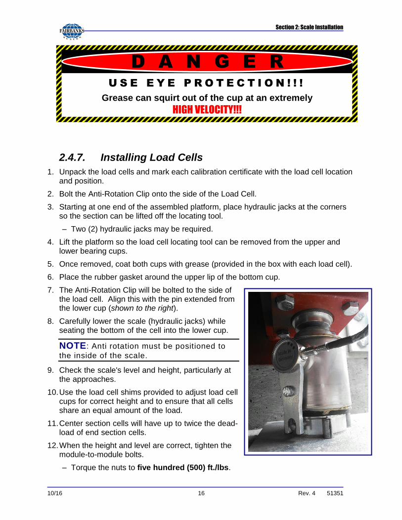
7. The Anti-Rotation Clip will be bolted to the side of the load cell. Align this with the pin extended from the lower cup (shown to the right).
8. Carefully lower the scale (hydraulic jacks) while seating the bottom of the cell into the lower cup.
NOTE: Anti rotation must be positioned to
the inside of the scale.
9. Check the scale's level and height, particularly at the approaches.
10. Use the load cell shims provided to adjust load cell cups for correct height and to ensure that all cells share an equal amount of the load.
11. Center section cells will have up to twice the dead-load of end section cells.
12. When the height and level are correct, tighten the module-to-module bolts.
– Torque the nuts to five hundred (500) ft./lbs.
U S E E Y E P R O T E C T I O N ! ! !
Grease can squirt out of the cup at an extremely
HIGH VELOCITY!!!
D A N G E R

Section 2: Scale Installation
10/16 17 Rev. 4 51351
2.4.8. Load Cell Cables
The cable protection on truck scales is extremely important to the reliability of the scale.
1. Route the load cell cables to the conduits that go across the bottom of the scale laterally. Route the junction box interface cables through the conduits that run longitudinally along the inside web of the side beams.
2. Coil the excess cables on the cable hanger on the interior of the I-Beams
Cable Hangers are located behind every SSC or PPS mounting block for all excess load call and interconnecting wire.
3. Once all wiring is complete, fasten all the cables together and hang them safely out of sight on the cable.
– In a correct installation, the only cables visible are those coming out of the holes in the side beam to the SSC or PPS.
2.4.9. Final Checking Adjustment
1. Adjust the End Checking Bolts to allow 1/16” to 1/8” clearance.
2. Adjust the Side Checking Bolts to allow 1/16” clearance from Bumper Block.

10/16 18 Rev. 4 51351
SECTION 3: ELECTRICAL INSTALLATION
3.1. Installation
The Titan scale was designed to be used with Intalogix™ systems. Intalogix™ systems utilize smart sectional controllers (SSC) and pit power supplies (PPS) for load cell excitation and signal processing.
Analog instruments cannot be used with this platform.
– The sensitivity using an analog indicator would be approximately a half microvolt (0.5mV).
– Most analog instruments have a minimum sensitivity of one microvolt (1mV).
There is one (1) SSC (Smart Sectional Controller) per section and one (1) PPS (Pit
Power Supply) for the entire platform.
– This applies to all scale installations unless the number and resistance of the cells require a second PPS.
– SSC Boxes have four (4) terminals.
▪ Two (2) are for load cells, and two (2) are for interfacing to other SSC boxes or terminating to a pit power supply.
▪ All cell/section/scale adjustments are made using the Intalogix™ system instrument.
3.1.1. Boxes
Mount the box with the brackets to the side of the Titan Modules.
3.1.2. Wiring
Cable used in all wiring must be a minimum of 18 AWG.
Use Cable 17204 or 17246.
Use appropriate service manual for the indicator being installed
For more information, see Appendix II: Four Section Intalogix Scale.

Section 3: Electrical Installation
10/16 19 Rev. 4 51351
3.1.3. Smart Sectional Controller (SSC)
Wire cells into each SSC according to the appropriate service manual.
For more information, see Appendix II: Four Section Intalogix Scale.
LOAD CELL WIRING
COLOR DESCRIPTION
Blue ‒ Excitation
Red + Excitation
Grey ‒ Signal
Green + Signal
Yellow Shield
3.1.4. Preventing Moisture Entry
The Titan Scale is designed to provide protection from the effects of moisture.
– Load cells are calibrated with the cable attached. DO NOT EVER cut the cable.
– The cable is connected directly to the SSC through a sealed bushing, which MUST be tightened properly to keep water/moisture out of the box.
– All cabling should have a drip loop at the cell or box entry location to help prevent water entry.
– On all boxes, particularly stainless steel, the black plastic fittings have "O" rings that can be forced out of position if the bushing itself is not tight.
▪ To prevent this, first tighten the inner nut securing the bushing in the hole, then insert cable and carefully tighten the gland until it is very snug.
▪ Do not over-tighten where bushing turns.
▪ Secure the cover with 10 in/lbs. for protection against moisture.
3.1.5. SCC Wiring
Wire the cells into each section’s SSC according to the appropriate manual.
Each SSC has connections for two (2) incoming load cells, labeled TB1 and TB2.
The odd numbered cell goes to TB1.
The even numbered cell goes to TB2.
Load cell drain wires connect to ground lug on the sectional controller box exterior.
Section 3: Electrical Installation
10/16 20 Rev. 4 51351
3.2. Wiring SSCs and PPSs for Intalogix Systems
3.2.1. Cell Numbering
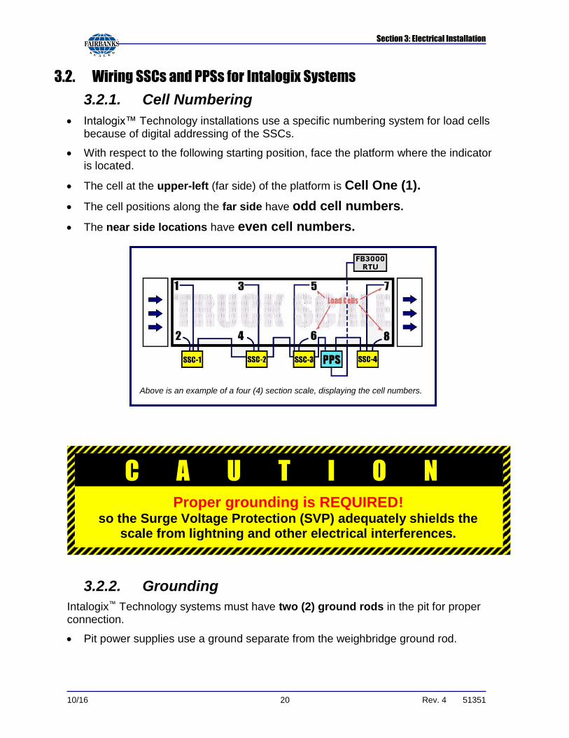
Intalogix™ Technology installations use a specific numbering system for load cells because of digital addressing of the SSCs.
With respect to the following starting position, face the platform where the indicator is located.
The cell at the upper-left (far side) of the platform is Cell One (1).
The cell positions along the far side have odd cell numbers.
The near side locations have even cell numbers.
3.2.2. Grounding
Intalogix™ Technology systems must have two (2) ground rods in the pit for proper connection.
Pit power supplies use a ground separate from the weighbridge ground rod.
Above is an example of a four (4) section scale, displaying the cell numbers.
C A U T I O N Proper grounding is REQUIRED!
so the Surge Voltage Protection (SVP) adequately shields the scale from lightning and other electrical interferences.

Section 3: Electrical Installation
10/16 21 Rev. 4 51351
3.2.3. Indicator-to-PPS Cable Connection
1. Prepare the cable ends in the standard manner.
– Use the appropriate manual for wiring instructions for the SSCs and PPSs.
2. Connect the indicator interface cable to the instrument in the scale house according to the instructions in the appropriate indicator service manual.
NOTE: For complete platform wiring details, see Load Cell-to-Interface Connections Service Manual (51326)

10/16 22 Rev. 4 51351
SECTION 4: MAINTENANCE
4.1. Scale Maintenance
Check for accumulations of solid material under the scale, which may affect the accuracy (ice, frozen mud, debris).
Check to see that the customer has cleaned under the platform regularly.
Inspect load cells for damage to the ends/cables; check cups for damage and/or excessive or uneven wear.
The load cell bearing cups should be inspected, cleaned, and greased at least TWICE per year.
Inspect and adjust all check bolts using anti-seize on the threads.
Inspect and tighten all connecting and coverplate hardware for proper tightness.
4.2. Mechanical Faults
Check all clearances around the scale for any obstructions of movement.
Check all check bolt clearances both with and without a concentrated load over each section, one at a time.
Check to be certain all load cells are plumb and level.
Inspect the boxes for leaks, the interior should be clean and dry.
– If there is moisture inside, clean then dry it out thoroughly.
– Check all connections at the terminal blocks to ensure they are tight.
4.3. RC Load Cell Replacement
1. REMOVE ALL POWER FROM THE INSTRUMENT.
2. Lift the scale using a proper sized and rated hydraulic jack(s) at the corner(s) closet to the defective load cell location.
3. Check upper and lower receiving cups, and the rubber gaskets for damage.
– Replace as necessary and reapply grease.
4. Insert the new cell into the upper receiving cup and position the anti-rotation clip to the inside of the scale.
5. Carefully lower the hydraulic jack(s) until the cell is set into the lower cup.
6. Remove the cover of the SSC/Balance box.

Section 4: Maintenance
10/16 23 Rev. 4 51351
7. Loosen the gland bushing to free the cable.
8. Remove the old cell wires and connect new cell wires in the balance Box/SSC.
9. Secure the cover, tightening all gland nuts.
10. Power-up, test and adjust the scale, as necessary.

10/16 24 Rev. 4 51351
SECTION 5: PARTS
5.1. Load Cells and Associated Hardware
All these parts are necessary for installing the Titan HV Truck Scale.
PART NO. DESCRIPTION
175115 * Load Cell, 411/16” RC, 50t, 100 Ohm, 2mV/V (Sartorius PR6221)
157277 Shim, Lower Cup, 1/16”
64338 Shim, Upper Cup, 1/8”
64334 Shim, Lower Cup, 3/16”
161197 UPPER & LOWER Cup (w/anti-rotation pin) Kit with Gasket
157278 Roll Pin, 3/8” x 1-1/4, Cup Retainer Baseplate
156264 Anti-Rotation Clip
107118 Locating Tool, 4 3/4”
157982 Rubber Gasket for Lower Cup
* Includes Upper & Lower Cups
5.2. Other Scale Hardware
PART NO. DESCRIPTION
76708 1 1/8" -7 x 8" Threaded Rod, Zinc (module-module)
54788 1 1/8" Lock Washer (module-module)
54306 1 1/8" SAE Flat Washer (module-module)
156965 Load Cell Base Plate
61743 Clamp Bar Washer (base plates)
62857 5/8" x 6" Anchor Bolts (wedge type)
55010 Ground Rod Kit
161398 * Shim, Upper Cup, 1/8" (2.25 OD)
161397 * Shim, Lower Cup, 1/16” (2.75 OD)
75398 Side check bracket w/bumper bolts (1” x 6½”)
79747 Rub Rail PVC End Caps
105297 Rub Rail Plugs
* See Image (below)

10/16 25 Rev. 4 51351
SECTION 6: ACCESSORIES
6.1. Accessories
Noted below are some of the available accessories for the Talon Truck Scale.
PART NO. DESCRIPTION
107587 Dress Plate Cover Kit [one (1) per order]
108302 2” Load Cell Riser Plate
108304 4” Load Cell Riser Plate
108307 7” Load Cell Riser Plate
153720 Safety Stairs (for installation information, see manual 51337)
144411 Guide Post Kit
17246 50’ Home Run Cable
NOTE: For additional information on Rub Rails, Deck Runners and other
accessories, see the Heavy Duty Parts Catalog.
6.2. Field Installed Rub Rails
1. Disconnect all load cells.
– Electrically isolate the load cells from the platform.
2. Use the print with the accessory for actual measurements.
3. Thoroughly clean and remove any primer around the areas to be welded.
– This allows for good welding penetration.
4. Weld the stiffeners to the side weldments.
5. Bolt the gussets to the stiffeners and end weldments.
6. Weld the pipe to the gussets.
7. Clean and paint all welded sections of the Rub Rails.
– This paint is normally provided.

Section 6: Accessories
10/16 26 Rev. 4 51351
Fairbanks does NOT recommend using foundation-mounted Rub Rails along the sides of this truck scale platform.
Damage may occur to the scale if a truck hits the Rub R ail, transferring damaging force to the platform and the checking system.
Using the wrong Rub Rail type will
VOID T H E PRODUCT WARRANTY.
W A R N I N G !

10/16 27 Rev. 4 51351
APPENDIX I: FOUNDATION CHECK LIST

Appendix I: Foundation Checklist
10/16 28 Rev. 4 51351
Appendix I: Foundation Check List, Continued

10/16 29 Rev. 4 51351
APPENDIX II: SCALE CONNECTIONS

10/16 30 Rev. 4 51351
APPENDIX III: SCALE DIMENSIONS
Titan Steel Deck 6020 Series
Product Number Model
L W CLC Capacity No. of Sections feet feet K lbs tons
10 ft.
165027 6020 27 10 120 75 2
165030 6020 30 10 120 75 2
165035 6020 35 10 120 75 2
165060 6020 60 10 120 125 3
165070 6020 70 10 120 125 3
165080 6020 80 10 120 150 4
165090 6020 90 10 120 150 4
165006 6020 105 10 120 150 4
11 ft.
165127 6020 27 11 120 75 2
165130 6020 30 11 120 75 2
165135 6020 35 11 120 75 2
165160 6020 60 11 120 125 3
165170 6020 70 11 120 125 3
165180 6020 80 11 120 150 4
165190 6020 90 11 120 150 4
165106 6020 105 11 120 150 4
12 ft.
165227 6020 27 12 120 75 2
165230 6020 30 12 120 75 2
165235 6020 35 12 120 75 2
165260 6020 60 12 120 125 3
165270 6020 70 12 120 125 3
165280 6020 80 12 120 150 4
165290 6020 90 12 120 150 4
165206 6020 105 12 120 150 4
14 ft.
165427 6020 27 14 120 75 2
165430 6020 30 14 120 75 2
165435 6020 35 14 120 75 2
165460 6020 60 14 120 125 3
165470 6020 70 14 120 125 3
165480 6020 80 14 120 150 4
165490 6020 90 14 120 150 4
165406 6020 105 14 120 150 4

Fairbanks Scales, Inc. 821 Locust Kansas City, Missouri 64106 www.fairbanks.com
Manufactured by Fairbanks Scales, Inc. 821 Locust
Titan Series Truck Scale
Installation Manual
51351