5.2. views - ida-step
TRANSCRIPT

IDA-STEP User Guide
Contents1. Overview 2. About 3. Register, Update and Install 4. Preferences 4.1. 3D View 4.1.1. Display Styles 4.2. GD&T 4.2.1. Annotation Style 4.3. General 4.3.1. Keys 4.3.2. Language 4.3.3. Network Connections 4.3.4. Perspectives 4.3.5. Virtual Machine Memory 4.4. Help 4.5. Numbers 4.5.1. Quantities and Units 4.6. PCB Stratums Cross-section 4.6.1. Color Schemas 5. General User Interface Elements 5.1. Workbench Window Layout 5.2. Views 5.2.1. Opening View 5.2.2. Moving and Docking View 5.2.3. Detaching View 5.2.4. Minimizing and Maximizing View 5.2.5. Fast Viewing 5.2.6. Resizing View 5.2.7. Find Text 5.2.8. Sorting 5.3. Perspectives 5.3.1. Open Perspective 5.3.2. New Perspective 5.3.3. Customize Perspective 5.3.4. Reset Perspective 5.3.5. Switching Between Perspectives 5.4. Toolbars 5.4.1. File buttons 5.4.2. GD&T buttons 5.4.3. Datum buttons 5.4.4. Tool buttons 5.5. Statusbar 5.6. Workbench Menus 5.6.1. File menu 5.6.2. Edit menu 5.6.3. GD&T menu 5.6.4. Constructive 5.6.5. Window menu 5.6.6. Help menu

6. File Handling 6.1. New File 6.2. Opening File 6.3. Import 6.3.1. Import Wizard 6.3.2. Importing Preferences 6.3.3. Importing EAGLE 6.3.4. Importing Data from CSV File 6.3.5. Importing Board Station 6.3.6. Importing Allegro 6.3.6.1. Importing Allegro Designs 6.3.6.2. Importing Example Data 6.3.7. Importing CircuitCAM 6.3.8. Importing PADS 6.3.9. Importing CR-5000 6.3.10. Importing Expedition 6.3.11. Importing CADIF 6.4. Export 6.4.1. Export Wizard 6.4.2. Exporting Preferences 6.4.3. Exporting STEP: 2D PCA/PCB data Extruded to 3D 6.4.4. Exporting STEP (ISO 10303 - part 21) 6.4.5. Exporting to CSV 6.4.6. Exporting to STL 6.4.7. Exporting to VRML 6.4.8. Exporting to CircuitCAM 6.5. Manage Libraries 6.5.1. 3D Part Libraries 6.5.2. E-CAD to M-CAD Mapping 6.6. Language 7. Installed Features 7.1. Electronics 7.2. GD&T Editor 7.3. IDA-STEP Framework 7.4. Import Allegro 7.5. Import Board Station 7.6. Import CADIF 7.7. Import CircuitCAM 7.8. Import CR-5000 7.9. Import EAGLE 7.10. Import Expedition 7.11. Import PADS 7.12. Layer Stack Editor 7.13. Viewer Basic 7.14. Viewer Pro 3D 8. Pre-defined Perspectives 8.1. GDT 8.2. Parts 3D 8.3. PCB Layer Library 8.4. PCB Layer Stack 8.5. PCB/PCA 8.6. Tasks 9. Available Views 9.1. 2D Viewer 9.1.1. Opening 2D Data View

9.1.2. 2D View 9.1.3. Zoom In 9.1.4. Zoom Out 9.1.5. Zoom to Fit 9.1.6. Zoom to Highlighted 9.1.7. Zoom Window 9.1.8. Highlight Object 9.1.9. Display Settings 9.2. 3D Viewer 9.2.1. Displaying Geometry in 3D View 9.2.2. Overview of 3D View 9.2.3. Predefined Orientations 9.2.4. Save Current 3D View 9.2.5. Appearance Style 9.2.6. Style/Annotation Model 9.2.7. Selection Modes 9.2.8. View Control 9.2.9. Front and Back Clipping 9.2.10. Inspecting Model 9.2.11. Measuring 9.2.12. Optimize Geometry 9.2.13. Re-triangulate 9.2.14. Management of GD&T Elements 9.2.14.1. Datum Feature 9.2.14.2. Datum Target 9.2.14.3. Datum System 9.2.14.4. Geometric Tolerances 9.2.14.5. Dimensions 9.2.14.6. Annotation Plane 9.2.14.7. Text Annotation 9.2.14.8. Shape Aspect 9.2.14.9. Constructive Geometry Elements 9.2.14.9.1. Apex 9.2.14.9.2. Symmetry Axis 9.2.14.9.3. Symmetry Plane 9.2.14.9.4. Symmetry Point 9.2.14.9.5. Common Line 9.2.14.9.6. Common Plane 9.2.14.9.7. Intersection 9.2.14.9.8. Offset 9.2.14.9.9. Perpendicular Line 9.2.14.9.10. Perpendicular Plane 9.2.14.9.11. Extension 9.2.14.9.12. Tangent Plane 9.2.14.9.13. Point 9.2.14.9.14. Line 9.2.14.9.15. Plane 9.2.14.10. Align Offset 9.3. Datasets 9.3.1. Datasets View 9.3.2. Creating Dataset 9.3.3. Renaming Dataset 9.3.4. Removing Dataset 9.4. Design Stack Models 9.4.1. Design Stack Models View
9.4.2. Creating Design Stack Model 9.4.3. Editing Design Stack Model Data 9.5. Documents 9.5.1. Documents View 9.5.2. Document Hierarchy 9.5.3. Creating New Document 9.5.4. Adding Version 9.5.5. Adding File 9.5.6. Adding File Reference 9.6. FMECA 9.6.1. FMECA View 9.6.2. Creating Failure Mode 9.6.3. Creating Failure Cause 9.6.4. Editing Failure Mode Data 9.6.5. Editing Failure Cause Data 9.6.6. Removing 9.7. GD&T 9.7.1. GD&T View 9.7.2. Shape Aspects 9.7.2.1. Composite Shape Aspect 9.7.2.2. Constructive Geometry 9.7.2.2.1. Create Apex 9.7.2.2.2. Create Symmetry Axis 9.7.2.2.3. Create Symmetry Plane 9.7.2.2.4. Create Symmetry Point 9.7.2.2.5. Create Common Line 9.7.2.2.6. Create Common Plane 9.7.2.2.7. Create Intersection 9.7.2.2.8. Create Offset 9.7.2.2.9. Create Perpendicular Line 9.7.2.2.10. Create Perpendicular Plane 9.7.2.2.11. Create Extension 9.7.2.2.12. Create Tangent Plane 9.7.3. Annotation Plane 9.7.4. Datum Feature 9.7.5. Datum Target 9.7.6. Datum System 9.7.7. Dimensions 9.7.8. Geometric Tolerances 9.7.9. Text Annotation 9.8. Geometry Details 9.8.1. Geometry Details View 9.8.2. Selection 9.8.3. Construction Geometry Models 9.8.4. Style/Annotation Models 9.8.5. Saved Views 9.8.6. Editing Visibility 9.8.7. Editing Colors 9.8.8. Editing Transparency 9.8.9. Editing Transformation Data 9.9. Header 9.9.1. Header View 9.10. Log 9.10.1. Log View 9.11. Maintenance Activities

9.11.1. Maintenance Activities View 9.11.2. Creating Maintenance Activity 9.11.3. Editing Maintenance Activity Data 9.11.4. Removing Maintenance Activity 9.12. Part Details 9.12.1. Part Details View 9.12.2. Selection 9.12.3. Visibility and Transparency 9.12.4. Editing Part Details 9.12.5. Create Assembly from Parts 9.12.6. Adding Component 9.12.7. Adding 3D Part to Library 9.12.8. Copying and Pasting 9.12.9. Removing 9.13. Parts 9.13.1. Parts View 9.13.2. Part Classifications 9.13.3. Creating Part Version 9.13.4. Creating New Version 9.13.5. Copying and Pasting 9.13.6. Editing Data 9.13.7. Assigning Part Version to Classification 9.13.8. Removing Part Version from Classification 9.13.9. Creating Classification System 9.13.10. Creating Classification 9.13.11. Creating Classification Attribute 9.13.12. Deleting 9.13.13. Moving 9.14. Passage Technologies 9.14.1. Passage Technologies View 9.14.2. Creating Passage Technology 9.14.3. Editing Passage Technology Data 9.15. Passages 9.15.1. Passages View 9.15.2. Passages Hierarchy 9.15.3. Creating Passage 9.15.4. Editing Passage Data 9.16. Persons and Organizations 9.16.1. Persons and Organizations View 9.16.2. Editing Person Data 9.16.3. Editing Organization Data 9.16.4. Editing Position Data 9.16.5. Editing Address Data 9.16.6. Creating New Element 9.16.7. Copying and Pasting 9.16.8. Deleting 9.16.9. Moving Element 9.16.10. Removing from Organization 9.17. Products 9.17.1. Products View 9.17.2. Creating Product 9.17.3. Editing Product Data 9.17.4. Removing Product 9.18. States 9.18.1. States View

9.18.2. Creating State 9.18.3. Adding Sub State 9.18.4. Editing State Data 9.18.5. Removing 9.19. Stratum Technologies 9.19.1. Stratum Technologies View 9.19.2. Creating Stratum Technology 9.19.3. Editing Stratum Technology Data 9.20. Stratums 9.20.1. Stratums View 9.20.2. Stratums Hierarchy 9.20.3. Creating Layer 9.20.4. Creating Sequential Group 9.20.5. Changing Layer Position 9.20.6. Moving Autorow to Root 9.20.7. Editing Layer Data 9.21. Stratums Cross-section 9.21.1. Stratums Cross-section View 9.21.2. Toggling Collapsed/Exploded view 9.21.3. Changing Color Schema 9.21.4. Highlighting Components 9.22. Tasks 9.22.1. Tasks Window 9.22.2. Task Hierarchy 9.22.3. Editing Task Data 9.22.4. Creating Task 9.22.5. Moving 9.22.6. Removing 9.22.7. Assigning Task Invocation 9.22.8. Assigning Zonal Breakdown 9.22.9. Assigning Part 9.22.10. Assigning Position 9.22.11. Assigning Auxiliary Materials 9.22.12. Assigning Tools 9.23. Zonal Breakdowns 9.23.1. Zonal Breakdown View 9.23.2. Zonal Breakdown Hierarchy 9.23.3. Creating Zonal Breakdown 9.23.4. Editing Zonal Breakdown Data 9.23.5. Assigning Position 9.23.6. Moving 9.23.7. Removing 10. Dynamic columns 10.1. Customizing views 10.2. Inserting Column 10.3. Removing Column 10.4. Configuring Column 10.5. Insert Column Wizard 10.6. Column types 10.6.1. Activity 10.6.2. Approval 10.6.3. Assembly component definition 10.6.4. Certification 10.6.5. Classification 10.6.6. Chosen method

10.6.7. Curve Color 10.6.8. Description 10.6.9. Date 10.6.10. Date and Time 10.6.11. Design 10.6.12. Document 10.6.13. Element 10.6.14. External data exists 10.6.15. External file location 10.6.16. ID 10.6.17. Magnitude 10.6.18. Material property 10.6.19. Name 10.6.20. Network assignment 10.6.21. Person / Organization 10.6.22. Position 10.6.23. Security 10.6.24. Subject 10.6.25. Surface Color 10.6.26. Text property 10.6.27. Transformation 10.6.28. Transparency information 10.6.29. Quantity 10.6.30. FMECA Specific 10.6.30.1. Enumeration property 10.6.30.2. Failure detection method 10.6.30.3. Failure effect 10.6.30.4. FMECA RPN 10.6.31. LSE Specific 10.6.31.1. Allocated technology 10.6.31.2. Allowed component terminal extent 10.6.31.3. Conductive layers 10.6.31.4. Connected minimum annular ring 10.6.31.5. Finished deposition thickness 10.6.31.6. Finished passage extent 10.6.31.7. From 10.6.31.8. Laminate stiffness class 10.6.31.9. Layer position 10.6.31.10. Maximum aspect ratio 10.6.31.11. Maximum feature size requirement 10.6.31.12. Minimum aspect ratio 10.6.31.13. Minimum finished feature size 10.6.31.14. Minimum finished feature spacing 10.6.31.15. Minimum finished size 10.6.31.16. Minimum interior extent 10.6.31.17. Passage deposition material attribute 10.6.31.18. Passage deposition material identification 10.6.31.19. Passage filling material attribute 10.6.31.20. Passage filling material identification 10.6.31.21. Passage terminus condition 10.6.31.22. Plated passage 10.6.31.23. Stratum purpose 10.6.31.24. Stratum technology material designation 10.6.31.25. Stratum technology occurrence base 10.6.31.26. Stratum technology occurrence definition

10.6.31.27. Stratum technology occurrence number 10.6.31.28. Stratum thickness 10.6.31.29. Technology type 10.6.31.30. To 10.6.31.31. Total thickness 10.6.31.32. Unconnected minimum annular ring 10.7. Columns perspective 10.7.1. Open columns perspective 10.7.2. Create columns perspective 10.7.3. Rearange columns 10.7.4. Restet default columns perspective 11. Printing 12. Errors and Warnings 12.1. Reporting Errors 12.2. Installation Errors 12.2.1. Error: Insufficient disc space on drive C: 12.2.2. Error: Failed to connect to https://services.ida-step.net/ through the Internet 12.3. Licensing Errors 12.3.1. Error: License ID not found 12.3.2. Error: License is blocked 12.3.3. Error: No rehostings left 12.4. Internal error
1. OverviewIDA-STEP is an extensible software system for handling many different aspects of industrial product model data. It is very tightly linked with STEP, the "STandard for the Exchange of Product model data", ISO 10303.The underlying infrastructure of IDA-STEP consists of:
• Java programming language • Eclipse for all GUI and installation aspects (see www.eclipse.org) • JSDAI for handling product data (see www.jsdai.net)
The functionality of IDA-STEP is wrapped up in software components that are called features by the underlying Eclipse system. We use both terms in this documentation. By licensing and installing more software components the functionality of IDA-STEP can be increased step by step. You can check for the licensed software components together with an optional expiration date and optional installation status in the Register, Update and Install dialogue that you can start from the Help menu.You can check for the currently installed software components and the exact version number of the component by starting About IDA-STEP dialogue from the Help menu and then clicking on Feature Details. The following kind of features are available:
• IDA-STEP Framework for handling the main aspects of the Graphical User Interface (GUI) and all aspects on registration, installation and update.
• Viewer Basic for being able to view the contents of a STEP File. • Viewer Pro xxx for extended viewing capabilities in a particular area, e.g. for 3D or PCB/PCA. • Editor xxx for editing capabilities in some area xxx. • Import xxx for being able to import files of format/type xxx. • Export xxx for being able to export files in some other format.
This help documentation will cover only those features that are currently installed on your PC.
Free annual licenses are available for the features IDA-STEP Framework and Viewer Basic. They don't need any special license-id to run on your computer. For all other features a license-id is needed which
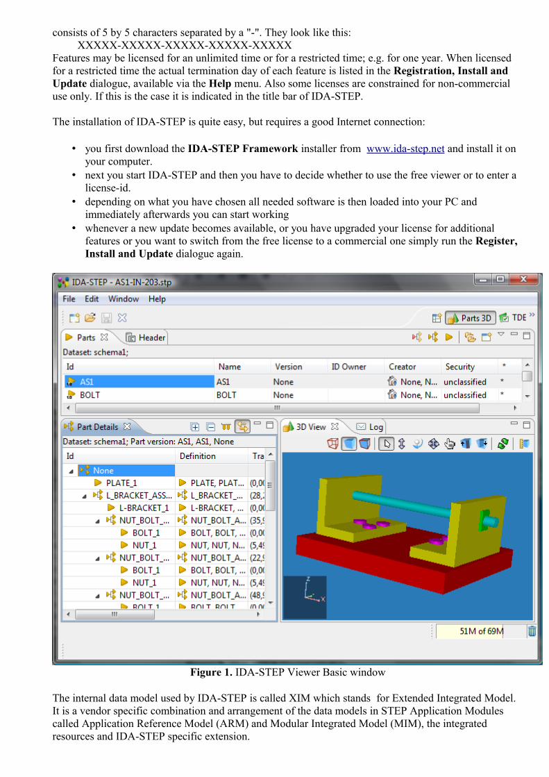
consists of 5 by 5 characters separated by a "-". They look like this: XXXXX-XXXXX-XXXXX-XXXXX-XXXXXFeatures may be licensed for an unlimited time or for a restricted time; e.g. for one year. When licensed for a restricted time the actual termination day of each feature is listed in the Registration, Install and Update dialogue, available via the Help menu. Also some licenses are constrained for non-commercial use only. If this is the case it is indicated in the title bar of IDA-STEP.
The installation of IDA-STEP is quite easy, but requires a good Internet connection:
• you first download the IDA-STEP Framework installer from www.ida-step.net and install it on your computer.
• next you start IDA-STEP and then you have to decide whether to use the free viewer or to enter a license-id.
• depending on what you have chosen all needed software is then loaded into your PC and immediately afterwards you can start working
• whenever a new update becomes available, or you have upgraded your license for additional features or you want to switch from the free license to a commercial one simply run the Register, Install and Update dialogue again.
Figure 1. IDA-STEP Viewer Basic window
The internal data model used by IDA-STEP is called XIM which stands for Extended Integrated Model. It is a vendor specific combination and arrangement of the data models in STEP Application Modules called Application Reference Model (ARM) and Modular Integrated Model (MIM), the integrated resources and IDA-STEP specific extension.

IDA-STEP is able to process data from various applications and based on different STEP Application Protocols (APs). Most APs are supported during Import and for Export the focus is on:
• AP203 edition 2, Configuration controlled 3D designs of mechanical parts and assemblies; • AP210 Electronic assembly, interconnect and packaging design; • AP214 Core data for automotive mechanical design processes; • AP239 Product life cycle support.
Data according the XIM model is stored in binary files with the extension ".xim". XIM files can be loaded significantly faster than standard STEP Files with the extension ".stp" and can also contain additional information such as rendered 3D models for fast viewing.
To top
Copyright © 2007-2011 LKSoftWare GmbH. All Rights Reserved.JSDAI is a registered trade mark of LKSoftWare GmbH.
2. AboutThe About IDA-STEP dialogue provides legal information about IDA-STEP and details about the installed version and configuration. (see Figure 1). To open this dialog, select in the main menu bar Help -> About IDA-STEP.
Figure 1. About IDA-STEP dialogue page
When pressing the Feature details button, the About IDA-STEP Features dialog is opened. It displays table, that lists the installed features. The columns are:
• Provider - the organization, which created the feature. In most cases this is LKSoftWare GmbH.
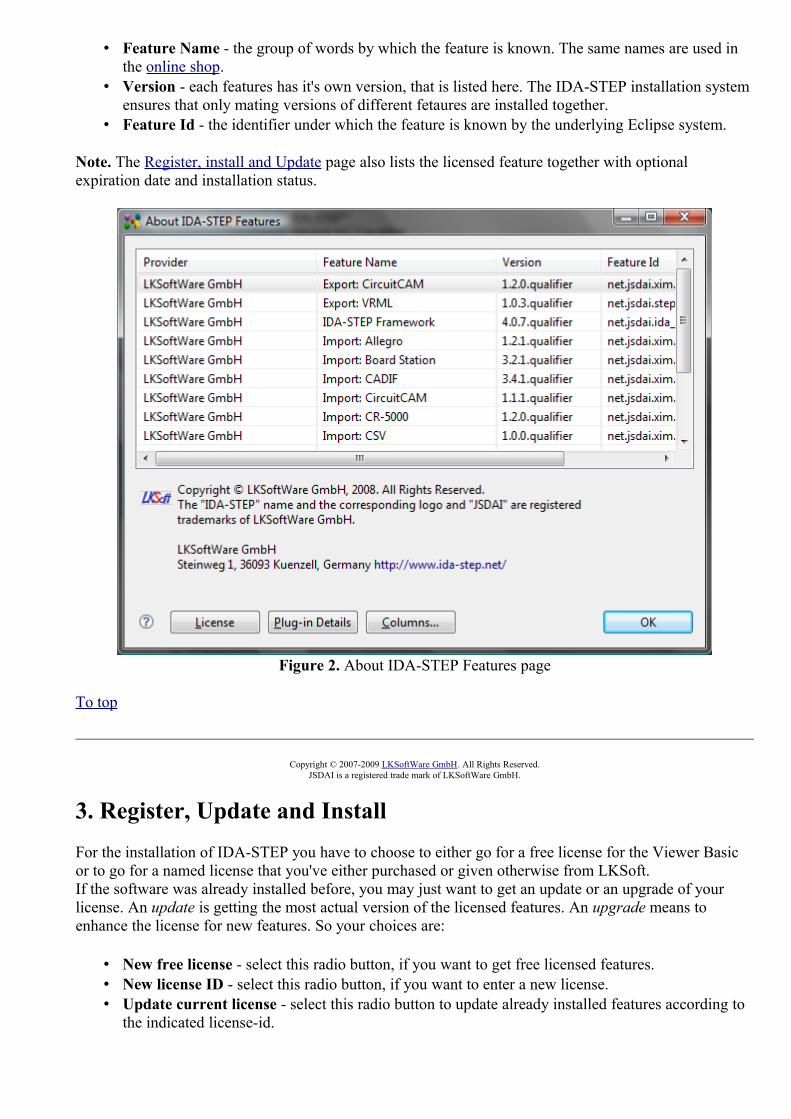
• Feature Name - the group of words by which the feature is known. The same names are used in the online shop.
• Version - each features has it's own version, that is listed here. The IDA-STEP installation system ensures that only mating versions of different fetaures are installed together.
• Feature Id - the identifier under which the feature is known by the underlying Eclipse system.
Note. The Register, install and Update page also lists the licensed feature together with optional expiration date and installation status.
Figure 2. About IDA-STEP Features page
To top
Copyright © 2007-2009 LKSoftWare GmbH. All Rights Reserved.JSDAI is a registered trade mark of LKSoftWare GmbH.
3. Register, Update and InstallFor the installation of IDA-STEP you have to choose to either go for a free license for the Viewer Basic or to go for a named license that you've either purchased or given otherwise from LKSoft.If the software was already installed before, you may just want to get an update or an upgrade of your license. An update is getting the most actual version of the licensed features. An upgrade means to enhance the license for new features. So your choices are:
• New free license - select this radio button, if you want to get free licensed features. • New license ID - select this radio button, if you want to enter a new license. • Update current license - select this radio button to update already installed features according to
the indicated license-id.
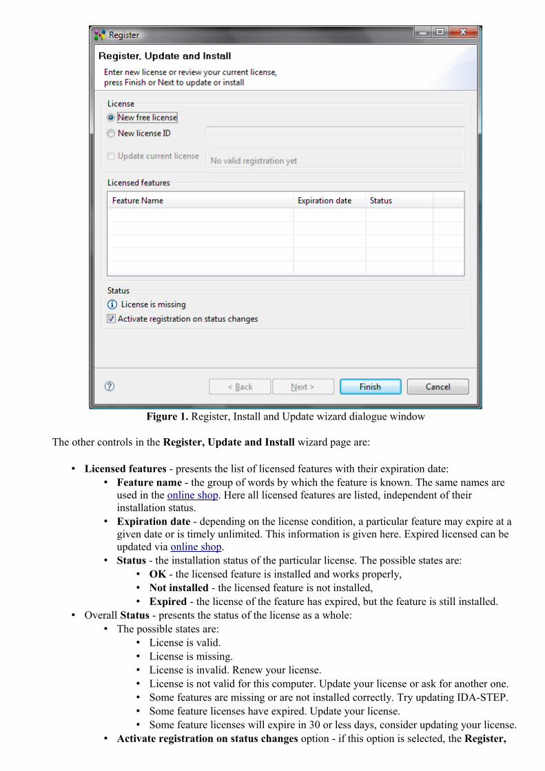
Figure 1. Register, Install and Update wizard dialogue window
The other controls in the Register, Update and Install wizard page are:
• Licensed features - presents the list of licensed features with their expiration date: • Feature name - the group of words by which the feature is known. The same names are
used in the online shop. Here all licensed features are listed, independent of their installation status.
• Expiration date - depending on the license condition, a particular feature may expire at a given date or is timely unlimited. This information is given here. Expired licensed can be updated via online shop.
• Status - the installation status of the particular license. The possible states are: • OK - the licensed feature is installed and works properly, • Not installed - the licensed feature is not installed, • Expired - the license of the feature has expired, but the feature is still installed.
• Overall Status - presents the status of the license as a whole: • The possible states are:
• License is valid. • License is missing.• License is invalid. Renew your license.• License is not valid for this computer. Update your license or ask for another one.• Some features are missing or are not installed correctly. Try updating IDA-STEP.• Some feature licenses have expired. Update your license.• Some feature licenses will expire in 30 or less days, consider updating your license.
• Activate registration on status changes option - if this option is selected, the Register,

Update and Install window is pop upped every time you start IDA-STEP when the state of the license is changed:
You can switch this option Off, by unselecting the check box. The Registration and Licensing Status dialogue window appears on the screen (see Figure 2), where you can select whether to disable the future activation of the registration on status changes or not. If you agree with the affirmation, press Yes button.
Figure 2. Registration and Licensing Status dialogue window, proposing to disable activation of registration on status changes
If you want to enable the activation of a registration on status changes in the future - select the Activate registration on status changes check box. The Registration and Licensing Status dialogue window appears on the screen with the message "Enable activation of registration on status changes" (see Figure 3). If you agree with the affirmation, press Yes button.
Figure 3. Registration and Licensing Status dialogue window, proposing to enable activation of registration on status changes
Register
After IDA-STEP Framework is started for the first time, the Register, Update and Install wizard pop ups on the screen. If you want to update license-id, or update installed features select the Register, Update and Install menu item in the Help menu.
• Select New free license radio button to get free IDA-STEP Viewer (see Figure 1) and press Finish button. The IDA-STEP Viewer will be installed.Note. To install Free IDA-STEP viewer, the current computer should be with the Internet access.Or
• Select New license ID radio button and enter a new license-id into the text field (see Figure 4). • Press Finish button to install new licensed features or press Next button to open the Registration
and Installation Method dialogue to choose how to register and install IDA-STEP. Note. The Next button is disabled for the free license installation.

Figure 4. Register new license
To top
Update
If you want update already licensed features:
• Select the Update current license radio button in the License layout (see Figure 1). • The licensed features are indicated in the Licensed features table. • Click Finish button or press Next button to open the Registration and Installation Method
dialogue to choose how to register and install IDA-STEP.
If no new features or updates are available for the currently activated license, the particular message window appears on the screen (see Figure 6).
Figure 6. Problem Occurred message window
To top
Registration and Installation Method
The user can choose how to register a new license or update licensed features - online or offline - in the Registration and Installation Method page (see Figure 7).

Figure 7. Registrations and Installation Methods page
Online registration and installation
The default registration and installation method is Online registration and installation. This option must be selected if your computer is currently connected to the Internet. IDA-STEP will connect to the license server and will register your license automatically. This is the default and simplest way.If any problem occurred while the registration and installation, please see Troubleshooting for details.
Offline registration, installation and update
If your computer is not connected to the Internet, you can use offline installation method.
• Select the Offline registration, installation and update radio button in the Registration and Installation Method page (see Figure 7).
• Press Next button. The Offline Registration and Installation page appears on the screen to choose the action for offline registration, installation or update (see Figure 8):

Figure 8. Offline Registration and Installation page (displayed license here: 5QL5A-CYBDE-6XIM4-04H8Q-4Q14E)
• Select the 1st Step: Preparation of HTML file for registration radio button. IDA-STEP will generate an HTML file with the needed registration data (IDA-STEP_xxxxx-xxxxx-xxxxx-xxxxx-xxxxx.html). Transfer this HTML file to another computer with internet access. Select a location of the file to be generated in your file system by using Browse... button next to the text field.Or
• Select the Skip 1st step radio button if the HTML file is already created during previous registration or update sessions.
• Press Next button to go to the next page of the wizard (see Figure 9). After the Next button is pressed the HTML file is generated and located in the selected place (in our example 5QL5A-CYBDE-6XIM4-04H8Q-4Q14E.html).

Figure 9. Offline Registration and Installation wizard page to select license file and installation/update package
• 1st step completed layout presents information, that HTML file is successfully created. Note. This layout is skipped, if the Skip 1st step radio button was selected in the previous page.
• 2nd step: Registration and downloading registration and installation file layoutOn another computer with Internet access access open the HTML file generated in step 1 in a web-browser and press the Register button.By this your registration data is transferred to the the registration server and if all is OK you will be offered to download and save two files:
• the license file IDA-STEP_xxxxx-xxxxx-xxxxx-xxxxx-xxxxx.lic • and the installation/update package with the licensed features IDA-STEP_xxxxx-xxxxx-
xxxxx-xxxxx-xxxxx_install_vYYYYMMDD.zip.
You have to transfer both files to the computer on which you want to install IDA-STEP. Meanwhile you will get a license file and installation/update package, you can close the wizard page by pressing Cancel button. Later you can open it by selecting Help -> Register, Update and Install menu item in the main menu bar and using Next button go to the needed page..
After you receive the license file (.lic), you can activate your license on your computer, where IDA-STEP should be installed.
• 3rd step: Activation of the license and updating or installing licensed feature layout: • Specify the path to the license file (IDA-STEP_xxxxx-xxxxx-xxxxx-xxxxx-xxxxx.lic) by

using Browse button next to the Read in the license file (IDA-STEP_xxxxx-xxxxx-xxxxx-xxxxx-xxxxx.lic) text field (see Figure 10).
Figure 10. Installation and Registration 3rd step
• Specify the path to the installation/update package IDA-STEP_xxxxx-xxxxx-xxxxx-xxxxx-xxxxx_install_vYYYYMMDD.zip by using Browse button next to the Read in the installation/update package with the licensed features (IDA-STEP_xxxxx-xxxxx-xxxxx-xxxxx-xxxxx_install_vYYYYMMDD.zip) text field.
• Press Finish button to activate the license and update/install licensed features.
To top
Copyright © 2007-2011 LKSoftWare GmbH. All Rights Reserved.JSDAI is a registered trade mark of LKSoftWare GmbH.
4. PreferencesThe Preferences dialog is the dialog used to set user preferences (see Figure 1). The Preferences dialog pages can be searched using the filter function. To filter by matching the page title, simply type the name of the page you are seeking and the available pages will be presented below. The filter also searches on keywords such as appearance and java. The history controls allow you to navigate through previously viewed pages. To step back or forward several pages at a time, click the drop down arrow and a list of the most recently viewed preference pages will appear.
The Preferences dialog can be found from the main workbench Window menu under Window > Preferences. Preference pages contributed by plug-ins will be found in this dialog.

Figure 1. Preferences page
The IDA-STEP preferences can be exported in EPF (preferences file) format and imported into some other installation of IDA-STEP (reference Importing and Exporting Preferences).
To top
Copyright © 2007-2009 LKSoftWare GmbH. All Rights Reserved.JSDAI is a registered trade mark of LKSoftWare GmbH.
4.1. 3D View
The 3D View preference page defines settings for the 3D View page (see Figure 1):
• Front side (right, up) combo box , • Projection type , • Zooming direction ,• Point size for dimension inspection , • Point size for construction geometry , • Precision used by the system , • Coordinate system size .

Figure 1. 3D View preferences page
Front side (right, up)
The Front side is a default orientation in the 3D View. All other predefined orientations, such as Top, Bottom, Right and etc. are derived from the Front orientation data (e.g. Top is 90 degrees rotation about axis, which points to the right, etc.).The Front side (right, up) combo box lists all 24 possible combinations. They are indicated by which axis go to the right and which axis go to the top, e.g. "+x,+z", meaning that the positive x axis points to the right and the positive z axis points to the top (see Figure 2).
Figure 2. 3D object Front side view, right axis X, up axis Z (+x, +z)
To restore the default Front side orientations, press the Restore Defaults button on the bottom section of

the preferences page.
Projection type
The Projection type determines whether geometry in the 3D View is displayed using an orthogonal or perspective projection. To switch between projection types select one of radio buttons:
• Central (Perspective) - this projection incorporates foreshortening (the size of an object's dimensions along the line of sight are relatively shorter than dimensions across the line of sight ) (see Figure 3). Parallel lines in the data may not appear parallel on screen.
• Parallel (Axonometric, Orthogonal) - this projection maintains the correct relative dimensions of graphics objects with regard to the distance a given point is from the viewer and draws parallel lines in the data parallel on the screen (see Figure 4).
Figure 3. Geometry presentation, when Central (Perspective) projection type is selected
Figure 4. Geometry presentation, when Parallel (Axonometric, Orthogonal) projection type is selected
Zooming direction
The default default zoom direction in the 3D View:
• Up - zoom out. Scroll mouse wheel or press CTRL + move mouse towards you to zoom out and away from you to zoom in.
• Up - zoom in . Scroll mouse wheel or press CTRL + move mouse towards you to zoom in and away from you to zoom out.

Point size for dimension inspection
The default point size for dimension inspection points.The default size value is 6 mm.
Point size for construction geometry
The default point size for construction geometry points. The default size value is 6 mm.
Precision used by the system
The default precision used by the system (10^(-x)) in millimetres. The default size value is 6 mm.
Coordinate system size
Size of coordinate system for annotation plane. The default size value is 6 mm. Note. Axes are visible for an annotation plane only when it is selected.
See also Display Styles.
To top
Copyright © 2009-2010 LKSoftWare GmbH. All Rights Reserved.D viewerJSDAI is a registered trade mark of LKSoftWare GmbH.
4.1.1. Display StylesFor displaying 3D geometry models by default IDA-STEP uses the default style schema, which is present in STEP data. A user can create a new default style and make it active for a geometry model in the 3D View, remove the redundant or incorrect style, modify a set of properties of the selected style, such as background, ambient light, diffuse light colours, element/component colours, transparency, highlighting and dark-lighting colours. The Display Styles settings are stored in a preferences file.The Display Styles preferences configuration page is composed of several sections:
• Top section of the window - to select, create, remove, make active a particular style; • General tab - to set background, ambient light and diffuse light colours (see General tabbed
panel); • Element Colors tab - change display preferences for a geometry model, construction geometry
and annotation (see Element Colors tabbed panel);• Component Colors tab - to change colour and transparency for a surface, colour for a curve and
vertex point for an assembly component. Also highlighting and dark-lighting colours can be changed in this tab (see Component Colors tabbed panel).
Note. The Display Style default settings would be overridden by any available styling data in a styling model.
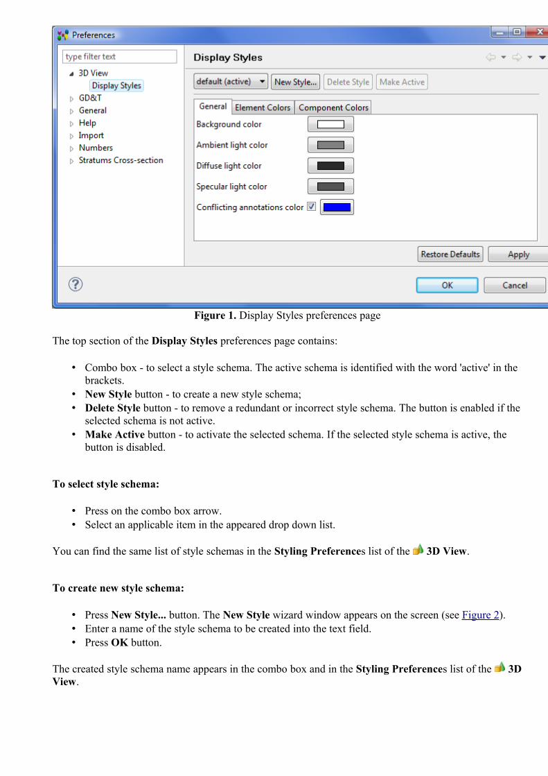
Figure 1. Display Styles preferences page
The top section of the Display Styles preferences page contains:
• Combo box - to select a style schema. The active schema is identified with the word 'active' in the brackets.
• New Style button - to create a new style schema;• Delete Style button - to remove a redundant or incorrect style schema. The button is enabled if the
selected schema is not active.• Make Active button - to activate the selected schema. If the selected style schema is active, the
button is disabled.
To select style schema:
• Press on the combo box arrow. • Select an applicable item in the appeared drop down list.
You can find the same list of style schemas in the Styling Preferences list of the 3D View.
To create new style schema:
• Press New Style... button. The New Style wizard window appears on the screen (see Figure 2). • Enter a name of the style schema to be created into the text field. • Press OK button.
The created style schema name appears in the combo box and in the Styling Preferences list of the 3D View.

Figure 2. New Style wizard window
To remove style schema:
• Select a redundant or incorrect style schema in the combo box.Note. The style schema has to be not activated (without label '(active)').
• Press Delete Style button.
The style schema is removed from the combo box list and from the Styling Preferences list in the 3D View.
To make style schema active:
• Select an applicable style schema in the combo box list.Note. The selected schema has to be not activated (without label '(active)').
• Press Make Active button.
The selected schema is activated (the label '(active)' appears next to the style schema name).
To top
General tabbed panel
The General tab (see Figure 1) allows a user to select colour for a:
• background , • ambient light , • diffuse light , • specular light , and • conflicting annotations color (if the option is checked).
Note. The background, ambient light, diffuse light properties are in the bounds of a currently selected style and not a global property.
Background color
The Background parameter defines the colour of the area around geometry in the 3D View. The default background colour is white.

To change 3D View background color:
• Press on the coloured square button next to the Background label in the Display Styles preferences page and select an applicable colour in the appeared Color window. Confirm your selection by pressing OK button.
• Back to the preferences page. Press Apply or OK buttons to apply the selected colour.
The newly defined background colour is be displayed in the 3D View (see Figure 3).
Figure 3. 3D View with changed background colour
To restore the default Front side orientations and Background colour, press the Restore Defaults button on the bottom section of the preferences page.
Ambient light color
Ambient light is the general light that illuminates the entire geometry. It has no discernible source and no discernible direction. Ambient colour is the colour of an object where it is in shadow. This colour is what the object reflects when illuminated by ambient light rather than direct light.
To change ambient light color:
• Press on the coloured square button next to the Ambient light color label in the Display Styles preferences page. The Color dialogue window appears on the screen:
• Press Define Custom Colors button. • Define a new intensity of the colour.
• Confirm your selection by pressing OK button.• Back to the preferences page. Press Apply or OK buttons to apply the selected colour (see Figure
4).
a) b)
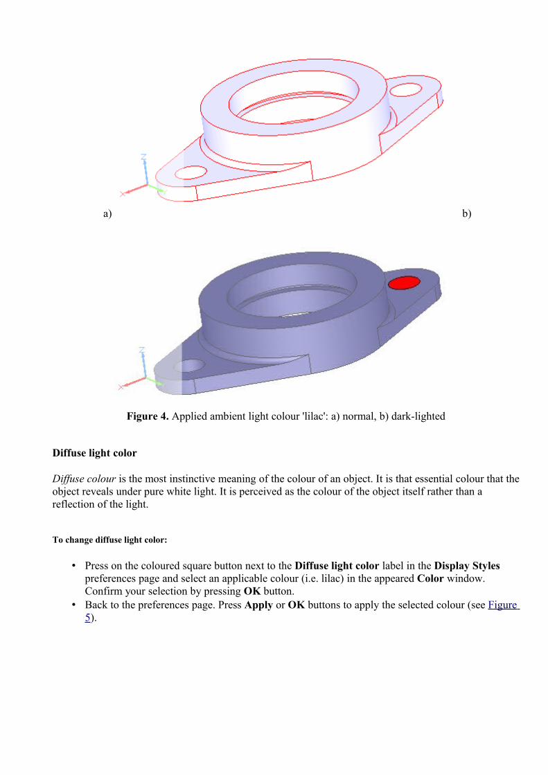
Figure 4. Applied ambient light colour 'lilac': a) normal, b) dark-lighted
Diffuse light color
Diffuse colour is the most instinctive meaning of the colour of an object. It is that essential colour that the object reveals under pure white light. It is perceived as the colour of the object itself rather than a reflection of the light.
To change diffuse light color:
• Press on the coloured square button next to the Diffuse light color label in the Display Styles preferences page and select an applicable colour (i.e. lilac) in the appeared Color window. Confirm your selection by pressing OK button.
• Back to the preferences page. Press Apply or OK buttons to apply the selected colour (see Figure 5).

a) b)
Figure 5. Diffuse light colour changed to 'lilac': a) normal, b) dark-lighted
Specular light color
Specular light - the light comes from a point source with specular lighting, it is reflected in the manner of a mirror where most of the light bounces off in a particular direction defined by the surface shape.
To change specular light color:
• Press on the coloured square button next to the Specular light color label in the Display Styles preferences page and select an applicable colour (i.e. lilac) in the appeared Color window. Confirm your selection by pressing OK button.
• Back to the preferences page. Press Apply or OK buttons to apply the selected colour (see Figure 6).

Figure 6. Specular light colour changed to 'lilac' (dark-lighted element)
Conflicting annotations color
Conflicting annotations color - the case, when the annotation colour in data is the same or very similar (differs ~5%) to the background colour. In this case the colour of annotations is changed to a different colour (default or specified by a user). A user may uncheck the Conflicting annotations color check mark, to apply the initial colour for annotations. Note. By default, this option is set On (see Figure 1) and a user is informed about the conflict in the Log view.
To change the default conflicting annotations colour:
• Press on the coloured square button next to the Conflicting annotations color label in the Display Styles preferences page and select an applicable colour in the appeared Color window. Confirm your selection by pressing OK button.
• Back to the preferences page. Press Apply or OK buttons to apply the selected colour.
To top
Element Colors tabbed panel
The Element Colors tabbed panel controls the default display preferences for a element, which is not an assembly component, and is presented as a single element in the 3D View (see Figure 7).

Figure 7. Element Colors tabFind below the list of configurable default properties:
• Geometric Model: • Surface • Surface transparency • Edge/Curve • Vertex/Point
• Construction Geometry: • Surface • Surface transparency • Edge/Curve • Vertex/Point
• Annotation: • Plane • Plane transparency • Text • Curve • Dimension curve • Leader curve • Projection curve • Fill area • Point • Symbol • Terminator symbol • Dimension curve terminator • Leader terminator • Subfigure
• Table
Columns of the table:
• Normal - properties for an element in a normal state - not selected, not darkligthed. • Highlighted - an element properties after it is selected/highlighted. • Darklighted - a colour of an element, when other component in an assembly is
selected/highlighted.
To change colour of an element:
• Press on a coloured square and select a colour in the appeared Color dialogue window. • Press OK button to confirm the selection.
To change transparency level for a surface:
• Enter a number value into the field.Or
• Use up or down arrow next to the text field to increase or decrease number value.
To top
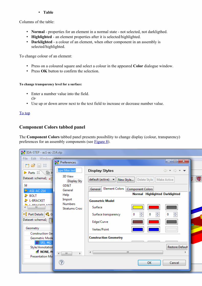
Component Colors tabbed panel
The Component Colors tabbed panel presents possibility to change display (colour, transparency) preferences for an assembly components (see Figure 8).
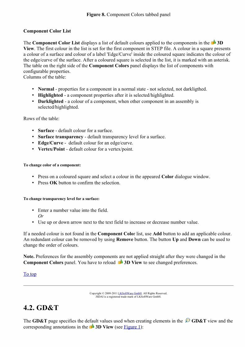
Figure 8. Component Colors tabbed panel
Component Color List
The Component Color List displays a list of default colours applied to the components in the 3D View. The first colour in the list is set for the first component in STEP file. A colour in a square presents a colour of a surface and colour of a label 'Edge/Curve' inside the coloured square indicates the colour of the edge/curve of the surface. After a coloured square is selected in the list, it is marked with an asterisk. The table on the right side of the Component Colors panel displays the list of components with configurable properties.Columns of the table:
• Normal - properties for a component in a normal state - not selected, not darkligthed. • Highlighted - a component properties after it is selected/highlighted. • Darklighted - a colour of a component, when other component in an assembly is
selected/highlighted.
Rows of the table:
• Surface - default colour for a surface. • Surface transparency - default transparency level for a surface. • Edge/Curve - default colour for an edge/curve. • Vertex/Point - default colour for a vertex/point.
To change color of a component:
• Press on a coloured square and select a colour in the appeared Color dialogue window. • Press OK button to confirm the selection.
To change transparency level for a surface:
• Enter a number value into the field.Or
• Use up or down arrow next to the text field to increase or decrease number value.
If a needed colour is not found in the Component Color list, use Add button to add an applicable colour. An redundant colour can be removed by using Remove button. The button Up and Down can be used to change the order of colours.
Note. Preferences for the assembly components are not applied straight after they were changed in the Component Colors panel. You have to reload 3D View to see changed preferences.
To top
Copyright © 2009-2011 LKSoftWare GmbH. All Rights Reserved.JSDAI is a registered trade mark of LKSoftWare GmbH.
4.2. GD&T
The GD&T page specifies the default values used when creating elements in the GD&T view and the corresponding annotations in the 3D View (see Figure 1):

• Default dimensioning standard - ISO and ASME have similar but different rules on how to apply GD&T and what is the exact meaning. Therefore it is essential to select one of them:
• ASME, or• ISO.
• Default length unit dimensions and tolerances - all GD&T specifications have to be done in the same unit. The radio group allows to identify whether the default unit is
• mm, or • inch.
• Default decimal places for GD&T - number of digits after the decimal separator for all length and area values. The numbers are rounded to this value.
• Show trailing zeroes for GD&T - if set indicates to show trailing zeroes after the decimal separator for length and area values; this is required by ASME. For ISO trailing zeroes are typically not shown and so this flag might be off.
• Default decimal places for geometry - number of places after the decimal separator for length and area values of geometric elements such as coordinates. All queried values from the 3D model and construction geometry are rounded to this value.
• Shape aspect name generation strategy - when creating GD&T element new features (shape_aspect) have to be created that corresponds to geometric_representation_items. Some CAD-Systems provide meaningful names for geometric_representation_items that might be used instead of creating new names, consisting of a prefix and a number:
• Use representation item name, if possible - use the name from the corresponding geometric_representation_item if available.
• Generate new - always generate a new name.
Figure 1. GDT preferences pageTo top
Copyright © 2010 LKSoftWare GmbH. All Rights Reserved.JSDAI is a registered trade mark of LKSoftWare GmbH.

4.2.1. Annotation StylesThe Annotation Styles page specifies styling parameters to be used when creating annotations (see Figure 1):
• Unit (mm, inch or mil) - specifies the measure units to be used for the style parameters listed below;
• Default way to display dimensions - there are several ways how dimension, especially diameter dimensions, can be shown:
• always with projection curves - a diameter dimension is presented with two projection lines. This case is used when (a) the annotation plane is perpendicular to the centre axis of a circle/cylinder or (b) when the annotation plane is in-line with a centre axis. This option is tuned On by default.
• without projection curves when possible - a diameter dimension is presented with a dimension line directly ending on the circle/cylinder or its extensions.
• Text height - height of all texts in an annotation; • Curve width - width of dimension, extension, reference and leader curves; • Terminator symbol size - size of terminator symbol; • Minimum reference line length - the minimum length for a reference line segment (continuous
narrow line connecting with the leader line horizontally or vertically and on or at which the additional instructions are indicated).
• Initial length of projection curve - initial length of projection curves; • Length of projection curve extension beyond dimension line - length of part of a projection
curve that extends beyond the dimension line; • Ideal window size - for 3D models up to this size and not smaller than a factor 2 or 2.5 an initial
scaling value of 1 is chosen. Otherwise IDA-STEP determines a proper enlargement or reduction scale.
Figure 1. Annotation Styles preferences pageTo top

Copyright © 2010-2011 LKSoftWare GmbH. All Rights Reserved.JSDAI is a registered trade mark of LKSoftWare GmbH.
4.3. GeneralThe General page displays setting for the workbench (see Figure 1). Each workbench window contains one or more perspectives. Perspectives contain views and control what appears in certain menus and tool bars. More than one workbench window can exist on the desktop at any given time.
Figure 1. General preferences page
• Select Always run in background check box to perform long running operations in the background without blocking you from doing other work.
• Select Keep next/previous editor, view and perspectives dialog open check box to remain open view cycle dialogs when their activation key is let go. Normally the dialog closes as soon as the key combination is release.
• Select Show heap status check box to display an indicator showing information about current Java heap usage. See also Virtual Machine Memory.
• You can select one of the following methods for opening resources in the Open mode layout:• Double click - Single clicking on a resource will select it and double clicking on it will
open it in an editor. • Single click (Select on hover) - Hovering the mouse cursor over the resource will select it
and clicking on it once will open it in an editor. • Single click (Open when using arrow keys) - Selecting a resource with the arrow keys will
open it in an editor.
Note: Depending on which view has focus, selecting and opening a resource may have different behavior.
To top
Copyright © 2009 LKSoftWare GmbH. All Rights Reserved.JSDAI is a registered trade mark of LKSoftWare GmbH.
4.3.1. KeysOn the Keys page, you can customize the function of the keyboard in IDA-STEP (see Figure 1). Within Eclipse, key strokes and key sequences are assigned to invoke particular commands.

A key stroke is the pressing of a key on the keyboard, while optionally holding down one or more of these modifier keys: Ctrl, Alt (Option on the Macintosh), Shift, or Command (only on the Macintosh.) For example, holding down Ctrl then pressing A produces the key stroke Ctrl+A. The pressing of the modifier keys themselves do not constitute key strokes.A key sequence is one or more key strokes. Traditionally, Emacs assigned two or three key stroke key sequences to particular commands. For example, the normal key sequence assigned to Close All in emacs is Ctrl+X Ctrl+C. To enter this key sequence, one presses the key stroke Ctrl+X followed by the key stroke Ctrl+C. A key binding is the assignment of a key sequence to a command.
Figure 1. Keys preferences page
• Scheme combo box contains a set of bindings. Choose the scheme you are most comfortable with by changing the Scheme setting on the keys preference page.
• Default scheme contains a general set of bindings, in many cases recognizable as traditional key sequences for well known commands. For instance, Ctrl+A is assigned to Select All, and Ctrl+S is assigned to Save.
• Emacs scheme contains a set of key bindings familiar to users of Emacs. For instance,

Ctrl+X H is assigned to Select All, and Ctrl+X S is assigned to Save.The Emacs scheme is not a complete set of bindings like the Default scheme. Rather, it borrows from the Default scheme where possible, only defining explicit Emacs-style bindings where they vary from the Default scheme. Generally, only well known commands like Select All, Save, etc. have specific Emacs key sequences associated with them. If you choose the Default scheme, all Emacs bindings are ignored. If you choose the Emacs scheme, explicit Emacs-style key sequence assignments take precedence over any conflicting assignments in the Default scheme.
• Filter field above the table with keys parameters. Enter a filter text to filter out commands relevant to the entered text.
• The table contains read only information: • Command - a name of the command, for which the key sequence is assigned.• Binding - indicates a key sequence, which is assigned to a particular command.• When - the context of IDA-STEP. This context is usually determined by the active part,
but it can be influenced by the active window or dialogue as well. If the active part does not choose a particular context, the workbench will set the active context to In Dialogs and Windows. Key bindings can vary based on the current context of IDA-STEP:
• Editing Text, • In Dialogs, • In Dialogs and Windows, • In Windows.
• Category - identifies the category of IDA-STEP context (Editor (for example 'GD&T'), Window, File and etc.).
• User - indicates that this is a user binding by displaying a U. If there was a conflict with another key, this column would also display a C. Note. In case of the conflict, the conflicted items are listed it the Conflicts table (see below).
• Copy Command button - press this button to create a second command entry for you to bind another key to.
• Unbind Command button - press this button to remove a key sequence (i.e. Binding value) for the selected command.
• Restore Command button - press this button to delete the binding. Note. All copies of the command will be removed (if any is previously created).
• Name field (read only) - this filed displays a name of the command, selected in the table.• Descriptions multi line field (read ) - presents additional information about the command, which
name is defined in the Name field.• Binding field - bind the command by putting focus in the Binding text box and pressing key
combination (for example 'CTRL+5') like you would if you were executing the command. • When combo box - select a context value in the drop down list.• Conflicts table - if the user sets a key binding and creates a conflict, the conflicting bindings will
be displayed in the conflicts list. This can be used to navigate between conflicting keybindings so that they can be changed. These types of conflicts can be resolved by explicitly assigning the key sequence to one of the commands, or remove it from the other.See Figure 2: There are listed two commands in the Conflicts list. The New Editor command has a user assigned (you can see U letter in the Users column) key stroke. The Undo command has a predefinde binding. The C letter in the Users columns informs about the conflict. Click on an applicable command in the Conflicts list and resolve the conflict by removing the binding or adding a new sequence of keys into the Binding field.

Figure 2. Conflicts list with defined conflicted bindings.
• Filters... button - filter out a list of commands in the table according to the category of IDA-STEP contexts. The When Context Filters window appears after the filter button is pressed (see Figure 3):
• Filter action set contexts - select this option not to show commands with action set contexts,
• Filter internal contexts - select this option not to show commands with internal contexts, • Filter uncategorized commands - select this option not to show commands with an
unrecognized context.Note. By default, all options are selected.
• Use OK button to confirm selections.
Figure 3. When Context Filters
• Export CSV... button - the list of binded command can be saved in external file of CSV format. Press this button, specify a filen name and a location in the file system for, and press Save button in the appeared Save as dialog window.
For more detailed information, refer the Eclipse documentation: Workbench User Guide > Reference > Preferences -> Keys .
To top
Copyright © 2011 LKSoftWare GmbH. All Rights Reserved.JSDAI is a registered trade mark of LKSoftWare GmbH.

4.3.2. LanguageOn the Language page you can set the default language for data by selecting an applicable language in the combo box.
Figure 1. Language page
To top
Copyright © 2009 LKSoftWare GmbH. All Rights Reserved.JSDAI is a registered trade mark of LKSoftWare GmbH.
4.3.3. Network ConnectionsBy default IDA-STEP is performing the license activation and software installation and update processes via direct Internet access to the central IDA-STEP license server. This is called Online registration,installation and update, see Register, Update and Install.
Depending on the kind of operating system you are using you may need to grant Internet Access to IDA-STEP to be able to do so. In most cases the default Direct connection to the Internet option is then sufficient for IDA-STEP to connect to the license server. But in some organisations special proxy servers are set up that have to be taken care. This is done in the Network Connections preference page described here:
• The System proxy configuration (if available) - this option is very useful, when the proxy is already configured in the user system. No additional configuration is needed.
• By default the Direct connection to the Internet option is selected. Enable this option to have all connections to remote systems happen directly without involving a proxy server.
• To allow connection to the remote server from behind the firewall, select the Manual proxy configuration option. The below fields are enabled. Specify needed options for the proxy server:
• HTTP proxy - Use this option to specify the server and port that is to be used when making HTTP connections. Enter URL into HTTP proxy field. Also you can specify a port in the Port field. If this field is empty, the default port of 80 is used. You can set On the option Use this proxy server for SSL. If this option is checked, the HTTP proxy server is used for SSL connections as well.
• Specify SSL proxy server location in the SSL proxy field. Use this option to specify the server and port that is to be used when making SSL connections. Optionally you can enter a port in the Port field. If this field is empty, the default port of 443 is used.
• Specify SOCK proxy server location in the SOCKS proxy field (please refer Wikipedia for more information about SOCKS). Optionally you can enter a port in the Port field. If this field is empty, the default port of 1080 is used.

Figure 1. Network Connections page
• No Proxy for - Use this table to specify, either by name or pattern, which hosts should not use any proxy but instead should always be connected to directly:
• Add a new host by clicking on Add Host button. The No proxy host names dialog window appears (see Figure 2).
• Specify a host name in the text field and click OK button.
Figure 2. Nor Proxy host names dialog window
• Enable proxy authentication - Enable this option to specify a User name and Password that is to be used when connecting to the proxy server.
• After all needed entries were filled, click OK or Apply buttons on the bottom section of the page to apply settings.
To top
Copyright © 2007-2009 LKSoftWare GmbH. All Rights Reserved.JSDAI is a registered trade mark of LKSoftWare GmbH.

4.3.4. PerspectivesOn the Perspective page you can select the following options for the launching of perspectives:
• Enable perspective switching - controls if user wants perspectives to be proposed. On by default. • Automatically switch single perspective - if On, IDA-STEP will auto switches perspective, if
there is only one perspective proposed to the user. This option is enabled for selecting only after the previous option is set On.
• GDT perspective - controls the switching of GDT perspective, when some GD&T data are created (available only with GD&T Editor feature):
• Always open - automatically switch perspective, if some geometric tolerance, dimension, or datum is created and the current perspective is not a GDT perspective.
• Never open - do not switch to GDT perspective automatically on the creation of GD&T elements.
• Prompt - prompt a dialogue window to select an applicable action.
Figure 1. Perspectives page
See also Pre-defined Perspectives.
To top
Copyright © 2007-2011 LKSoftWare GmbH. All Rights Reserved.JSDAI is a registered trade mark of LKSoftWare GmbH.
4.3.5. Virtual Machine MemoryThe Virtual Machine Memory controls the maximum amount of memory available to the Java Virtual Machine (JVM) that is used by IDA-STEP. The setting depends of the kind of operating system (Windows or Linux), the inner architecture (32 or 64 bit), the installed physical memory (e.g. 2 GByte) and other installed software packages. No fixed rule can be given about the maximum memory settings.
Figure 1. Virtual Machine Memory page
We have to distinguish between the current maximum size and the possible maximum size. The current maximum size is displayed in this dialogue and it is less or equal to the possible maximum size. But as explained above the possible maximum size is not know and thus can't be displayed.
The actual memory consumed and allocated by the JVM is displayed in the small Heap Status control in

the status bar (see Figure 2). The lower number is the amount of memory actual in use by the JVM and the upper number the amount of memory currently allocated from the operating system. The upper number is always smaller or equal to the current maximum size. The actual number of memory in use is dynamically growing and shrinking. It can be reduced when pressing the so called Garbage Collection button (waste bin symbol).See General preferences on how to switch the Heap Status control on and off.
Figure 2. Heap status with actual used and allocated memory
Example: Under Windows 32bit the maximum physical memory that can be managed by the operating system is about 3 GB. If you have installed more memory Windows can't take advantage of it. If you now try to set the maximum memory setting to e.g. 2.5 GB the JVM will not allow you to do so because a significant portion of the memory is reserved for the operating system. A typical maximum value under 32 Windows is 1.6 GB (or 1600 megabytes). But if IDA-STEP would allocate this whole amount of memory then other applications running in parallel would decrease in performance because windows has to swap in and out the applications between the hard disk and physical memory. If you need more memory than is available under 32 bit we recommend to switch to a 64 bit operating system with at least 6 GB.
Any change of the maximum size will only become effective after re-starting of IDA-STEP. The fields are (see Figure 1):
• Current maximum size as reported by JVM - the text field displays the actual max. memory available to the currently running JVM.
• New maximum size (will take effect after restart) - the new maximum value to be used the next time IDA-STEP is started anew.
Note that the initial values of current maximum size and new maximum size are often not identical, even after re-start. This is because the value the JVM is asking for and what it get by the system may differ. When entering new values for new maximum size IDA-STEP is dynamically checking with the operating system and if the value is not accepted by the system it will indicate this by the message "Invalid maximum memory value".The "new maximum size" value will be stored in the file ida-step.ini that you can find in the directory where IDA-STEP is installed. The line of interest looks like this -Xmx1500mfor a new maximum size of 1500 megabytes. Dependent of your kind of installation this directory may be write protected. In this case when you try to change the new maximum size you will see an error message like this:

Figure 3. Save Preferences dialogue window in failure case If you see this message you have to change this entry manually with some editor in protected mode.
To top
Copyright © 2007-2009 LKSoftWare GmbH. All Rights Reserved.JSDAI is a registered trade mark of LKSoftWare GmbH.
4.4. HelpOn the Help preferences page you can indicate, how to display the help information (see Figure 1).
Figure 1. Help preferences page
• Select the Use external browser check box to force help to use external browsers. • Select the open modes in the Open Modes layout:
• Open window context help in a dynamic help view/in an infopop - this option allows you to determine whether the window context help will be opened in a dynamic help view or in an infopop.
• Open dialog context help in a dialog try/in an infopop - this option allows you to determine whether the dialog context help will be opened in a dynamic help section of help view or in an infopop.
• Click OK or Apply buttons on the bottom section of the page to apply settings.
To top
Copyright © 2007-2009 LKSoftWare GmbH. All Rights Reserved.JSDAI is a registered trade mark of LKSoftWare GmbH.
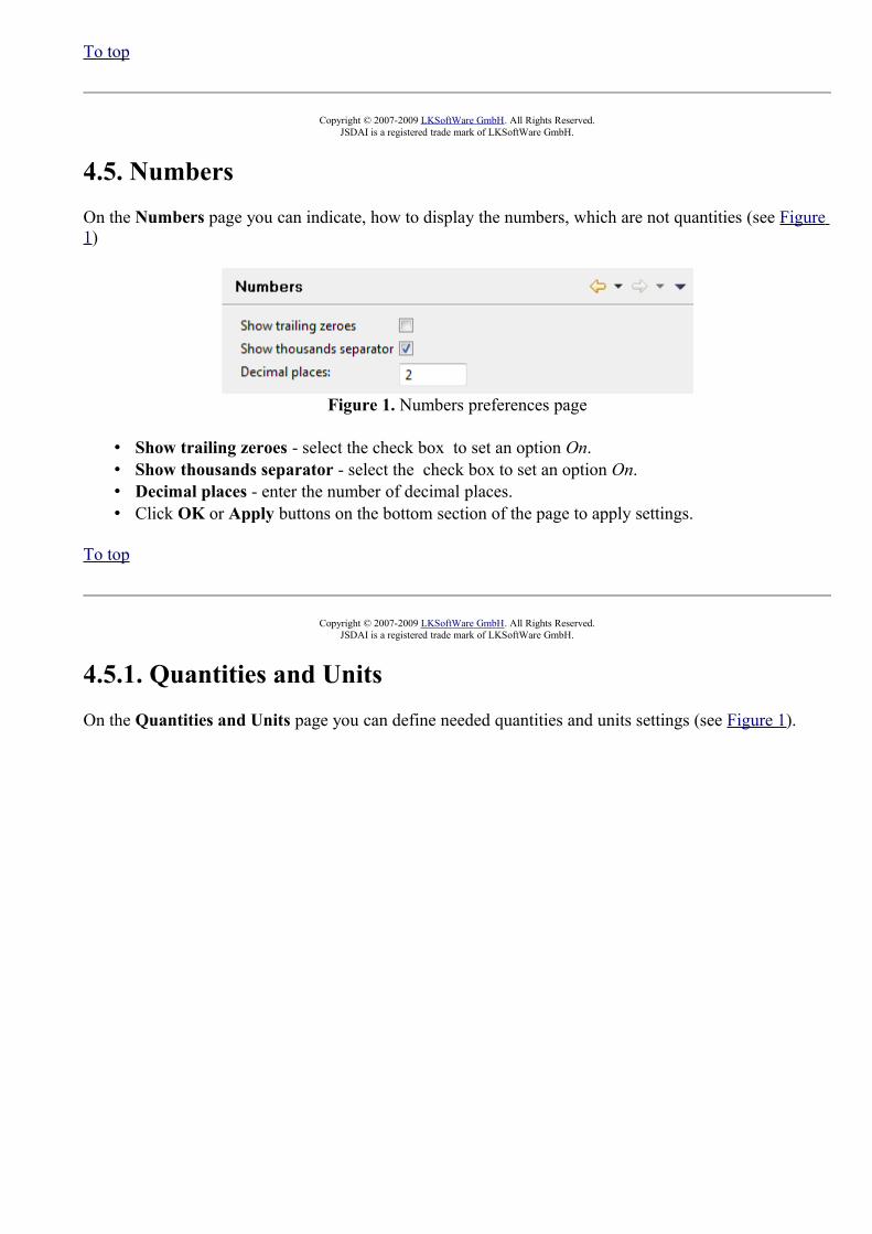
4.5. NumbersOn the Numbers page you can indicate, how to display the numbers, which are not quantities (see Figure 1)
Figure 1. Numbers preferences page
• Show trailing zeroes - select the check box to set an option On. • Show thousands separator - select the check box to set an option On. • Decimal places - enter the number of decimal places. • Click OK or Apply buttons on the bottom section of the page to apply settings.
To top
Copyright © 2007-2009 LKSoftWare GmbH. All Rights Reserved.JSDAI is a registered trade mark of LKSoftWare GmbH.
4.5.1. Quantities and UnitsOn the Quantities and Units page you can define needed quantities and units settings (see Figure 1).

Figure 1. Quantities and Units page
• Select an applicable quantity in the table on the top section of the page, where: • Quantity - the quantity name; • Source - the source of the selected quantity (ISO or user defined).
Or
• Add a new quantity by clicking on Add button next to the table. The New quantity wizard dialog window appears. Created quantity appears in the table.
Or
• Remove the redundant or incorrect quantity by using Remove button next to the table.
In the <quantity> settings layout the settings layout the setting for the selected quantity are displayed. The name of the layout is dynamic, it shows the currently selected quantity name (see Figure 1, the 'length' quantity is selected and displayed in the label of the layout).
• Use default unit for labels - if this option is On, the default unit label is displayed in the table cell (see Figure 2).
Figure 2. The table cell label
• Available units for the selected quantity are displayed in the list on the right side of the settings layout (see Figure 1):
• Use Add button to add a new unit into the list. The Unit wizard dialog window appears on the screen.
• Use Remove button to remove the incorrect or redundant value from the list. The default value can not be removed.
• Use Set As Default button to set the currently selected unit in the list is set as default unit.

• Show trailing zeroes - select the check box to set an option On. • Show thousands separator - select the check box to set an option On. • Decimal places - enter the number of decimal places.
• Click OK or Apply buttons on the bottom section of the page to apply settings.
To top
New quantity wizard
The New quantity wizard helps the user to create a new quantity:
• Enter a name of the quantity to be created into the Name field. • The table in the middle of the window displays the default unit settings for the quantity to be
created. • Select an applicable value from the Prefix drop down list. • Select a value from the Unit drop down list. • Enter an exponent value into the Exponent cell (available values -1, 1, 2 and 3). • Click Add button to add more components if needed. • The Label above the table displays the quantity representation.
Figure 3. New quantity wizard dialog window
• After all parameters are set, click OK button. The created quantity appears in the table (see Figure 4). The source of the created quantity is set to 'User defined'.

Figure 4. Created new quantity ('example quantity') in the tableTo top
Unit wizard
The Unit wizard helps the user to create a new unit for the selected quantity (see Figure 6).
• Select an applicable quantity in the Quantities and Units page table (see Figure 5) and click Add button next to the list of units in the force settings layout.
Figure 5. Quantities and Units page with displayed force settings

• The Unit wizard dialog window appears on the screen (see Figure 6):
Figure 6. Unit wizard dialog window
• Select an applicable value from the Prefix drop down list. • Select a value from the Unit drop down list. • Enter an exponent value into the Exponent cell (available values -1, 1, 2 and 3). • Click Add button to add more components if needed. • The Label above the table displays the quantity representation (see Figure 7).
Figure 7. Unit wizard dialog window with unit parameters
• Click OK button to create a new unit. The unit appears in the list in the settings layout (see Figure 8).
Figure 8. Created unit in the listTo top

Copyright © 2007-2009 LKSoftWare GmbH. All Rights Reserved.JSDAI is a registered trade mark of LKSoftWare GmbH.
4.6. PCB Stratums Cross-section
The Stratums Cross-section page displays the current settings for the Stratums Corss-section view (see Figure 1):
• Spacing between stratums - the vertical spacing in pixels between stratums in expanded view. • Number of feature spacings - a number of the feature spacings on most design stratums. This
number denotes how many gaps are drawn on each design stratum with Min. Feature Size and Min. Feature Spacing information available.
• Number of feature spacings for power or ground - a number of feature spacings on the power or ground design stratums. This number denotes how many gaps are drawn on each design stratum with Min. Feature Size and Min. Feature Spacing information available and Purpose set to 'Power or ground'.
• Spacing between passages - a horizontal spacing in pixels between passages. • Passage maximum plating multiplier - a multiplier denoting what width one passage plating can
occupy in a comparison to the whole passage width. • Minimum stratum width - a minimum width of a stratum in pixels. This is usually relevant only
when a design stack model has no features and no passages.• Laminate indentation - a horizontal distance between different levels of the laminate. This is also
a distance between two consecutive laminates on the same level.• Spacing between labels - a vertical spacing in pixels between labels in a collapsed view.• Feature trapezoid cut - a horizontal distance in pixels between corners of the feature trapezoids.
The distance is horizontal only and between corners on one side (left or right) of the trapezoid.• Padding between labels and stratums - a horizontal distance in pixels between labels and
stratums.• Vertical padding - a vertical distance in pixels between top of the picture area and a picture itself. • Horizontal padding - a horizontal distance in pixels between the left side of the picture area and a
picture itself.• Default plating width in pixels - a horizontal size in pixels of the passage plating when no
plating width is defined..

Figure 1. Stratums Cross-section preferences page
An applicable setting can be changed by entering a new value into the text field next to the setting label. To apply newly entered settings, press Apply or OK button on the bottom section of the page.
To top
Copyright © 2008-2009 LKSoftWare GmbH. All Rights Reserved.JSDAI is a registered trade mark of LKSoftWare GmbH.
4.6.1. Color SchemasOn the Color Schemas page (see Figure 1) you can edit default component, text font and background colors for the color schemas, create a new color schema and define your own colors for the component in one layer, label text and background.

Figure 1. Color Schemas preferences page, Component colors and Font and Background colors tabbed panels
You can select the schema to be applied for the current data by selecting an applicable value in the combo box on the top left corner of the page or create a new schema by clicking on the New Schema button next to the previously mentioned combo box.
To top

New schema
In order to create a new color schema, click on the New schema button on the top section of the Color Schemas page. The Create new Color Schema dialog window appears (see Figure 2):
Figure 2. Create new Color Schema wizard dialog window
• Enter a name for the new color schema into the text field. • Press OK button. A new schema is created and marked as selected for the current data - the name
of the newly created schema is presented in the combo box in front of the New Schema button (see Figure 3).
Figure 3. New schema name in the combo box in front of New Schema button
The colors for a newly created schema are the same as for the previously selected schema. You can change the color of the components in one layer in the Component color tabbed panel. To change text font and background color, go into the Font and Background colors tabbed panel.
To top
Deleting Color Schema
There is a possibility to remove a redundant or an incorrect color schema by using Delete Schema button on the bottom section of the page. Note: Only user created color schema can be removed. You can not remove default color schemas.
To top
Component colors
The Component colors tabbed panel presents the colors for a PCB library components in one layer (see Figure 4).

Figure 4. Component colors tabbed panel
You can change the color for the following:
• Stratum technology stratum purpose components:• Build-up material, • Core material, • Embedded passive capacitor dielectric, • Embedded passive resistor, • Coating, • Generic layer, • Glue, • Gluemask, • Lands only, • Signal, • Pastemask, • Power or ground, • Silkscreen, • Soldermask, • Solderpaste.
• Passage technology type components: • Component termination, • Border, • Unsupported, • Via.
• Via filling color.
You can change the following colors for the components:
• Normal - the regular color for the components. • Highlighted - the color of the highlighted component. • Dimmed - the color of the components, after one of other components/layers is highlighted.
To top
Font and background colors
In the Font and Background colors tabbed panel you can define text font of layer labels and background

color for the particular color schema (see Figure 5).
Figure 5. Font and Background colors tabbed panel
• Stratums cross-section font - format font for the labels of a regular layers (when layer is neither highlighted, nor dimmed).
• Stratums cross-section font when highlighted - format font for the label of the highlighted layer. • Stratums cross-section font when dimmed - format font for the label of the dimmed layer.
To change font formating, press Change button in a particular layout and select an applicable options in the appeared dialog window. You can preview the formated text in the text fields in front of Change button.
To top
Changing Colors
Follow the routine to change a color in the Color Schemas preferences page:
• Activate the Component colors tabbed panel.
• Click on the colored button ( ) in a table of colors. The Color dialog window appears on the screen (see Figure 6).

Figure 6. Color dialog window
• Click on an applicable color in the Basic color or Custom colors layout.
Or
• Define your custom color by clicking on the Define Custom Colors button. The additional part of the dialog window appears (see Figure 7):
Figure 7. Color dialog window to add custom colour
• Select a color and click Add to Custom Colors button. • A square with a chosen color appears in the Custom colors layout (on the left). • Click OK button.
• The color of the selected component is changed.
To top

Restoring Default Colors
If any default schema was modified, you can restore a default set of colors:
• Select an applicable default color schema in the list on the top section of the page. • Press Restore Defaults button on the bottom section of the page.
To top
Copyright © 2008-2009 LKSoftWare GmbH. All Rights Reserved.JSDAI is a registered trade mark of LKSoftWare GmbH.
5. General User Interface ElementsIDA-STEP is opening one workbench window for each XIM or STEP file. Like most other window applications IDA-STEP has a global menu, toolbar and a statusbar. Inside the main working area one or several views can show up. Each view may have its own individual toolbar. There is a wide range of possibilities on how the views can be arranged. A fixed collection of views at dedicated positions and sizes is called a perspective.
Figure 1. IDA-STEP Workbench

See also Workbench Window Layout Views Perspectives Toolbars Workbench Menus
To top
Copyright © 2009 LKSoftWare GmbH. All Rights Reserved.JSDAI is a registered trade mark of LKSoftWare GmbH.
5.1. Workbench Window LayoutYou can rearrange the layout of workbench windows as follows:
• Drag views to different positions within the workbench window. • Drag views such that they are simultaneously visible beside, above, or below another editor. • Resize views by dragging the sashes which separate them.
Drop Cursors
Drop cursors indicate where a view will dock when you release your mouse button. This indication is relative to the view or editor area underneath the cursor.Cursor Name Description
Dock above The view will appear above the view underneath the cursor.
Dock below The view will appear below the view underneath the cursor.
Dock to the right The view will appear to the right of the view underneath the cursor.
Dock to the left The view will appear to the left of the view underneath the cursor.
Stack The view will appear as a tab in the same pane as the view underneath the cursor.
Double Click
Double-clicking a view title bar maximizes the part in the workbench window.

Title Bar Context Menu
From the context menu of a view title bar, you can select how you want the view to appear within the workbench window.
Context menu option Description
Detached The part becomes a detached view (hosted in its own shell).
Restore Restores the view to its originating (non-maximized/non-minimized) size and position within the workbench.
ove Move the part or part group.
Size Change the size of the part in the direction specified.
Minimize Minimizes the part in the workbench window.
Maximize Maximizes the part in the workbench window.
Close Closes the part.
To top
5.2. ViewsViews provide alternative presentations or navigations of the information in the workbench. A view might appear by itself or stacked with other views in a tabbed notebook or a view may be closed and you can open it when needed.
To activate a view that is a part of a tabbed notebook simply click it's tab. The workbench provides a number of quick and easy ways to configure an environment, including whether the tabs are at the bottom or top of the notebooks.

Figure 1. Tabbed views, Geometry Detaisl view is active view
Views may have a context menu menu, which is accessed by right clicking on the view's tab, allows the view to be manipulated.
Figure 2. Title bar context sensitive menu
A view can be displayed by selecting it from the Window > Show View menu. A perspective determines which views may be required and displays these on the Show View sub-menu. Additional views are available by choosing Other... at the bottom of the Show View sub-menu. This is just one of the many features that provide for the creation of a custom work environment.

Figure 3. Dialog window invoked by Show view --> Other menu
To top
Copyright © 2007-2009 LKSoftWare GmbH. All Rights Reserved.JSDAI is a registered trade mark of LKSoftWare GmbH.
5.2.1. Opening ViewPerspectives offer pre-defined combinations of views. To open a view that is not included in the current perspective, select Window > Show View from the main menu bar. If a view is not listed in the appeared context menu, select Other... menu item. The Show views dialogue appears on the screen (see Figure 1).
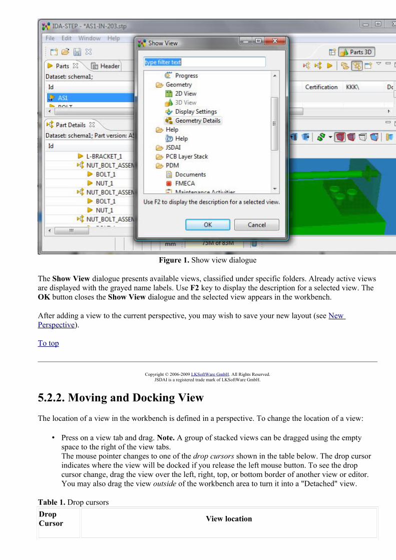
Figure 1. Show view dialogue
The Show View dialogue presents available views, classified under specific folders. Already active views are displayed with the grayed name labels. Use F2 key to display the description for a selected view. The OK button closes the Show View dialogue and the selected view appears in the workbench.
After adding a view to the current perspective, you may wish to save your new layout (see New Perspective).
To top
Copyright © 2006-2009 LKSoftWare GmbH. All Rights Reserved.JSDAI is a registered trade mark of LKSoftWare GmbH.
5.2.2. Moving and Docking ViewThe location of a view in the workbench is defined in a perspective. To change the location of a view:
• Press on a view tab and drag. Note. A group of stacked views can be dragged using the empty space to the right of the view tabs. The mouse pointer changes to one of the drop cursors shown in the table below. The drop cursor indicates where the view will be docked if you release the left mouse button. To see the drop cursor change, drag the view over the left, right, top, or bottom border of another view or editor. You may also drag the view outside of the workbench area to turn it into a "Detached" view.
Table 1. Drop cursors Drop Cursor View location

Dock above The view is docked above the view underneath the cursor.
Dock below The view is docked below the view underneath the cursor.
Dock to the right The view is docked to the right of the view underneath the cursor.
Dock to the left The view is docked to the left of the view underneath the cursor.
Stack The view is docked as a Tab in the same pane as the view underneath the cursor.
Detached The view is detached from the workbench window and is shown in its own separate windows.
• When the view is in the needed location, release the left mouse button.
The view or a stack of views may be moved by using context sensitive menu:
• Right click on a view title bar. The context sensitive menu appears on the screen: • Select Move menu item, then View - to move a view or Tab Group - to move stack of
views.
Figure 1. Context sensitive menu, Move menu item
• The drop cursor (see Table 1) and a dynamically moving square appears on the screen (see Figure 2).

Figure 2. Drop cursor and dynamically moving square
• Move with a mouse to locate the selected view or stack of views and click a mouse button.
Note. You can save changes in a new perspective (see New Perspective for more details).
To top
Copyright © 2009 LKSoftWare GmbH. All Rights Reserved.JSDAI is a registered trade mark of LKSoftWare GmbH.
5.2.3. Detaching ViewDetached views are views that are shown in a separate window with a smaller trim. They work like other views except they they are always shown in front of the workbench window (see Figure 1).

Figure 1. IDA-STEP workbench with detached 3D View
Follow the routine to detach a view:
• Right click on a view tab. • Select Detached menu item in the appeared context sensitive menu (see Figure 2). The selected
view is detached.
Figure 2. Context sensitive menu, Detached menu item
To attach the detached view back to the workbench:
• Right click on the detached view tab. • Select Detached menu item in the appeared context sensitive menu. The view is returned to the
initial position in the workbench.
The view may be detached by moving it outside the workbench window (see Moving and Docking View for more details). To restore the view to be shown inside of the workbench window, drag it into the workbench window.
To top

Copyright © 2009 LKSoftWare GmbH. All Rights Reserved.JSDAI is a registered trade mark of LKSoftWare GmbH.
5.2.4. Minimizing and Maximizing ViewA view in a workbench occupies an area, defined in a perspective. Some time it is convenient to have a maximized view, which takes as much area in the workbench as it can. Or some times it is needed to minimize a view temporary, the view takes an area as small as it can. There are some ways to manage minimizing and maximizing of a view area:
1. Using the minimize and maximize buttons provided on a stack's border; 2. Selecting the 'Minimize' or 'Maximize' item on the context sensitive menu for a stack; 3. Double-clicking on a stack; 4. Using 'Ctrl + M' keys: this is a key binding for a command that will toggle the currently active
view between its 'maximized' and its 'restored' (i.e. normal) states.
Figure 1. Minimizing/Maximizing ways
Maximize
It is desirable at times to focus your attention on one particular view to the exclusion of the others. The most popular candidate for this is maximizing the view area in order to make as much of the display

available for editing/viewing as possible (but there are workflows where it would make sense to focus on a view as well).IDA-STEP implements the maximize behavior by minimizing all stacks except the one being maximized. This allows the maximized stack to completely occupy the main presentation while still allowing access any open views in your perspective by using the icons in their Trim Stack (the area around the edges of the window is called the 'trim').
Figure 2. Maximized view in workbench
To top
Minimize
Another way to optimize the use of the screen area is to directly minimize stacks that are of no current interest. While minimizing a view or view stacks is moved into the trim area at the edges of the workbench window, creating a Trim Stack. View Stacks get minimized into a trim representation that contains the icons for each view in the stack (see Figure 3).

Figure 3. Stack View minimized to Stack Trim
If your particular workflow is such that you need to have more than one element (i.e. having the view area and a View Stack in the presentation at the same time) you can still gain additional screen space by minimizing the stacks that aren't of current interest. This will remove them from the main presentation and place them on the outer edge of the workbench window as Trim Stacks, allowing more space for the remaining stacks in the presentation (see Figure 2).
Note: There are two ways to end up with a stack in the trim:
• Directly minimizing the stack • As the result of another stack being maximized
Depending on how the Trim Stack was created its behavior is different; when un-maximizing only those trim stacks that were created during the initial maximize will be restored to the main presentation while stacks that were independently minimized stay that way.
This difference is important in that it allows you fine grained control over the presentation. While using maximize is a one-click operation it's an 'all or nothing' paradigm (i.e. no other stack is allowed to share the presentation with a maximized stack). While adequate for most tasks you may find yourself wanting to have the presentation show more than stack. In these scenarios don't maximize; minimize all the other stacks except the ones you want in the presentation. Once you have it set up you can still subsequently maximize the editor area but the un-maximize will only restore the particular stack(s) that were sharing the presentation, not the ones you've explicitly minimized.
To top
Copyright © 2009 LKSoftWare GmbH. All Rights Reserved.JSDAI is a registered trade mark of LKSoftWare GmbH.
5.2.5. Fast ViewingWhen views are minimized in to stack trims, they can be quickly opened and closed. Views are represented as a toolbar buttons. You can read a name of a particular view in the tool tips, which appear after the mouse is moved over a view icon button (see Figure 1).

Figure 1. IDA-STEP workbench view with stack trim and view button tool tip
When you click the toolbar button for a particular view, that view opens temporarily in the current perspective, overlaying the area it takes in a normal workbench presentation (see Figure 2). As soon as you click outside that view it is hidden again. The stack trim can also be docked on the other sides of the workbench window.
Figure 2. Temporary opened Parts view

See also Minimizing and Maximizing View.
To top
Copyright © 2009 LKSoftWare GmbH. All Rights Reserved.JSDAI is a registered trade mark of LKSoftWare GmbH.
5.2.6. Resizing ViewA size of a view in the IDA-STEP workbench may be changed in the following ways:
• Move a mouse pointer over the edge of a view. The resize mouse pointer appears. • Press the mouse button, hold and drag to available direction to resize the view area (see Figure 1). • Release the mouse button after the needed size of the view area is reached.
Figure 1. IDA-STEP workbench with resize mouse pointer
Another way to change size of a view is by using context sensitive menu:
• Right click on a view stack bar. The context sensitive menu appears on the screen. • Select Size -> <direction> menu item. Note. Only currently available resizing direction is enabled
(see Figure 2).

Figure 2. Context sensitive menu to resize view
• After an applicable resizing direction is selected, the particular edge of the view are is highlighted on the workbench (see Figure 3).
• Point with a mouse on the highlighted line. The resize mouse pointer appears. Press, hold and drag

to the needed direction. • Release the mouse button after the needed size of the view area is reached.
To top
Copyright © 2009 LKSoftWare GmbH. All Rights Reserved.JSDAI is a registered trade mark of LKSoftWare GmbH.
5.2.7. Find Text
The Find functionality allows you to quickly find and highlight text in a currently active view.
To find a particular text in a view:
• Select in the main menu bar Edit -> Find... menu item.Or
• Use key combination Ctrl+F.
The Find dialog appears on the screen (see Figure 1).
Figure 1. Find dialog window
Enter the text to find into the Find field and set an applicable options for the search. Use buttons Previous or Next to searh for the entered text. Note. After any button is pressed, the dialog is closed and the found text is highlighted in a view. To find the next occurrence of the search string, you have to open the Find window again. The previously eneterd string should be present in the Find field.
Options
• Case sensitive - check this option to match the capitalization you have entered. • Whole word - check this option to match the entire word entered as the search term. • Regular expression - check this option to match the regular expression entered as the search item.
Directions
To select the search direction - use one of the buttons:
• Previous - search through the records following the current record.

• Next - search through the records preceding the current record.
To top
Copyright © 2009 LKSoftWare GmbH. All Rights Reserved.JSDAI is a registered trade mark of LKSoftWare GmbH.
5.2.8. SortingIDA-STEP presents a possibility to arrange data in an ascending or descending order. Data can be sorted in an alpha-numerical order. The elements are sorted from left to right, i.e. a1, a2, a10, a11 and etc.This functionality is implemented only for those tree tables, where sorting is meaningful - the sorting does not damage the data structure. If the order of elements is strongly defined, the sorting of data is not available (i.e., Passages view, because stratums displayed under passage node have always to be sorted according to their order in design; Tasks view, because the order of elements in that view is important).
Figure 1. Part Details view, tree table with sorted assemblies
To sort elements in a view:
• Activate a view with a tree table. • Press with a mouse on a column to be sorted title. Data in the selected column is sorted (see Figure
1).
The sorting direction is indicated in the column title:
• Ascending order (triangle arrow up),
• Descending order (triangle arrow down).
To top
Copyright © 2009 LKSoftWare GmbH. All Rights Reserved.JSDAI is a registered trade mark of LKSoftWare GmbH.

5.3. PerspectivesA perspective defines the initial set and layout of views in the workbench window. One or more perspectives can exist in a single workbench window.
Perspectives define visible action sets, which can be changed to customize a perspective. A perspective that is built in this manner can be saved, creating a custom perspective that can be opened again later.
The workbench window displays one or more perspectives. Each product determines initially what default perspective is displayed, in this example it is the Parts 3D perspective (see Figure 1). The predefined perspectives are:
1. Parts 3D , 2. GD&T ,3. PCB/PCA , 4. PCB Layer Library , 5. PCB Layer Stack , 6. Tasks .
More than one workbench window can be open at any given time.
IDA-STEP presents functionality to choose perspective upon loading/importing of a file according to data in the file. The particular perspective is proposed in the dialog window after a STEP file is loaded/imported. After the user selects a perspective, it is opened in the workbench and in some cases the "key" view is activated as well. If there is only one perspective to choose for the selected file, it can be launched automatically in the future. This can be managed by selecting particular preferences in the Perspectives page (accessed by selecting Window-> Preferences-> General-> Perspectives).
The right click on the perspective button in the perspective bar invokes the context sensitive menu, which presents the following perspective options:
• Customize - customize the active perspective (reference Customize Perspective);• Save as - create a new perspective or update the existing one (reference New Perspective);• Reset - reset the active perspective to it's default layout (reference Reset Perspective);• Close - close the currently selected perspective.

Figure 1. Parts 3D perspective
To top
Copyright © 2007-2011 LKSoftWare GmbH. All Rights Reserved.JSDAI is a registered trade mark of LKSoftWare GmbH.
5.3.1. Open PerspectiveThere are several ways to open a new perspective within this workbench window:
• Using the Open Perspective button on the shortcut bar. • Choosing a perspective from the Window > Open Perspective menu.
To open one by using the shortcut bar button:
• Click on the Open Perspective button . • Choose Other from the menu. The Open Perspective dialog window appears (see Figure 1).

Figure 1. Open Perspective dialog window
• Select an applicable perspective from the list and click OK button. The selected perspective is displayed in the workbench.The title of the window now indicates which perspective is in use.The shortcut bar contains several perspectives. The selected perspective button is pressed in, indicating that it is the current perspective (see Figure 2).
Figure 2. The current perspective button
• To display the full name of the perspective right click the perspective bar and check Show Text.
To top
Copyright © 2007-2009 LKSoftWare GmbH. All Rights Reserved.JSDAI is a registered trade mark of LKSoftWare GmbH.
5.3.2. New PerspectiveThere is a possibility to add new views to the perspective and rearrange the views. The workbench also allows this layout to be saved for future use.
• Open an existing perspective in a workbench. • Add new views on it. • Right click on the active perspective button in the perspective bar. Select the Save As.. menu item
from the appeared context sensitive menu (see Figure 1).
Figure 1. Context sensitive menu
• The Save Perspective As... dialog window appears (see Figure 2).
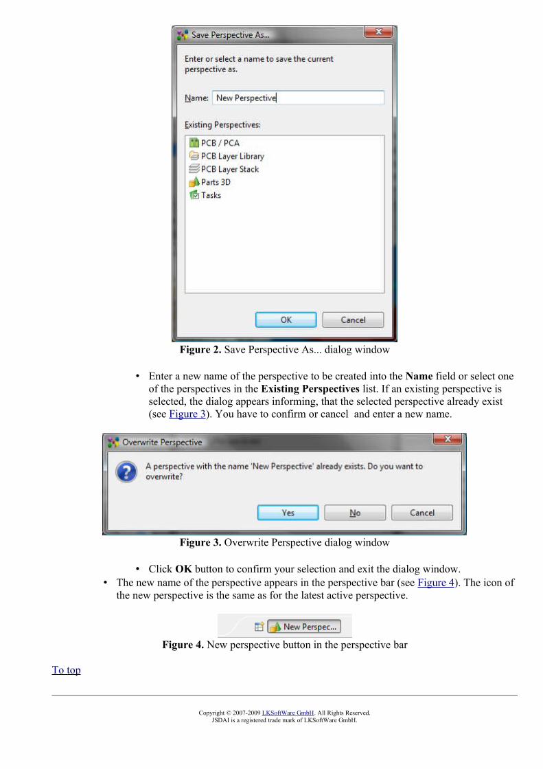
Figure 2. Save Perspective As... dialog window
• Enter a new name of the perspective to be created into the Name field or select one of the perspectives in the Existing Perspectives list. If an existing perspective is selected, the dialog appears informing, that the selected perspective already exist (see Figure 3). You have to confirm or cancel and enter a new name.
Figure 3. Overwrite Perspective dialog window
• Click OK button to confirm your selection and exit the dialog window. • The new name of the perspective appears in the perspective bar (see Figure 4). The icon of
the new perspective is the same as for the latest active perspective.
Figure 4. New perspective button in the perspective bar
To top
Copyright © 2007-2009 LKSoftWare GmbH. All Rights Reserved.JSDAI is a registered trade mark of LKSoftWare GmbH.

5.3.3. Customize PerspectiveIn addition to configuring the layout of a perspective you can also control several other key aspects of a perspective. These include:
• The visibility of individual menu and tool bar items.• The availability of command groups (groupings of menu items, tool bar items and key bindings). • The items in the Window --> Open Perspective, Show View menus.
To customize the current perspective:
• Right click on the perspective button in the perspective bar. • Select the Customize menu item from the appeared context sensitive menu. The Customize
Perspective <current perspective name> dialogue window appears (see Figure 1):
Figure 1. Customize Perspective Parts 3D dialogue window with active Tool Bar Visibility panel
Tool Bar Visibility
Choose which tool bar items to display. The checked box in front of a particular tool bar button icon means that this tool bar button is displayed in the tool bar. If the check box is empty - the particular button or group of buttons is not displayed in the tool bar.
• Select the Tool Bar Visibility tab. • Uncheck the File item in the Tool Bar Structure tree. • Press OK button.
The File group of buttons is no longer included in the main tool bar (see Figure 2).

Figure 2. Main tool bar with File group buttons and tool bar after it was customized
Menu Visibility
Choose which menu items to display. The checked box in front of a particular menu item means that this menu item is displayed in the main menu bar. If the check box is empty - the particular menu item is not displayed in the main menu bar.
• Select the Menu Visibility tab • Uncheck the File-> Open item in the Menu Structure tree. • Press OK button.
The GDT-> Create Constructive Geometry item is no longer included in the main menu (see Figure 3).
Figure 3. Menu with File->Open menu item and menu after it was customized
Command Groups Availability
Select the command groups that you want to see added to the current perspective. The details field identifies which menu items and/or tool bar items are added to the perspective by the selected command group.
Shortcuts
Select the shortcuts that you want to see added as cascade items to the selected sub menus. The selections made will only affect the current perspective.
• Click on the Shortcuts tab to activate the panel. • Select an applicable sub menu in the Sub menus combo box (i.e. Open Perspective). • Unselect shortcuts, which should not appear in the selected sub menu, by unselecting a particular

check box in front of the shortcut name (see Figure 4).
Figure 4. Customize Perspective Shortcuts wizard page with selected sub menu Open Perspective and list of available shortcuts
• Click OK button to confirm your selections and exit the dialogue window.
The unselected shortcuts are no longer displayed in the selected sub menu (see Figure 5).
Figure 5. Open Perspective sub menu content before and after shortcuts were unselectedTo top
Copyright © 2007-2011 LKSoftWare GmbH. All Rights Reserved.JSDAI is a registered trade mark of LKSoftWare GmbH.
5.3.4. Reset PerspectiveTo restore a currently opened perspective to its original layout:
• Right click on the active perspective button in the perspective bar. • Select Reset menu item in the appeared context sensitive menu (see Figure 1).

Figure 1. Context sensitive menu on the active perspective button
• The Reset Perspective dialog window appears asking whether you want to reset the current perspective to it's defaults or not (see Figure 2).
Figure 2. Reset perspective dialog window
• Press OK button to reset perspective or Cancel button to reject the resetting.
To top
Copyright © 2007-2009 LKSoftWare GmbH. All Rights Reserved.JSDAI is a registered trade mark of LKSoftWare GmbH.
5.3.5. Switching Between PerspectivesOpen perspectives are represented by icons on the perspective bar. When you have more than one perspective open, you can switch between them by clicking the icons on the shortcut bar.
To top
Copyright © 2006-2009 LKSoftWare GmbH. All Rights Reserved.JSDAI is a registered trade mark of LKSoftWare GmbH.
5.4. ToolbarsThere are three kinds of toolbars in IDA-STEP.
The main toolbar, sometimes called the workbench toolbar, is displayed at the top of the workbench window directly beneath the menu bar. The contents of this toolbar change based on the active perspective, installed features. Items in the toolbar might be enabled or disabled based on the state of either the active view or editor. Sections of the main toolbar can be rearranged using the mouse.
There are also individual view toolbars, which appear in the title bar of a view. Actions in a view's toolbar apply only to the view in which they appear. Some view toolbars include a Menu button, shown as an inverted triangle, that contain actions for that view.

A third type of toolbar is the perspective switcher (perspective bar). The perspective switcher allows quick access to perspectives that are currently open. It also has a button that can open new perspectives. The perspective switcher is normally located in the top-right, next to the main toolbar. However, it is also possible to position it below the main toolbar ("top-left"), or to position it vertically on the left-hand side of the workbench ("left"). The name of the perspectives is shown by default, but it is possible to hide the text and show only the icons. To reposition the perspective or hide the text, right-click on it and choose the appropriate item from the context menu.
In all cases, you can find out what toolbar buttons do by moving your mouse pointer over the button and reading the tooltip that opens. You can customize toolbars for each perspective - turn tool bar items on and off (refer clause Customize Perspective).
The following commmon buttons may appear in the workbench toolbar, toolbars for views:
Button Description
Open a new perspective
Hide view (Minimize)
Restore view (Maximize)
Open a help window
Search in a help window
View datasets of the selected view type
Open a new window of the active view
Go to top
Go back
Go in
Link with views
IDA-STEP also has a number of toolbars, which group together associated functions (depends on the installed features).
Hide/Show toolbar on Mac OS
There's a button to hide/show the toolbar on Mac OS. In case the toolbar is hidden and the application closed, the toolbar and the button to show it disappears. The Hide toolbar action is available through toolbar context menu.

In case the toolbar is hidden, the the Show toolbar command becomes visible in the Window main menu.
To top
Copyright © 2006-2011 LKSoftWare GmbH. All Rights Reserved.JSDAI is a registered trade mark of LKSoftWare GmbH.
5.4.1. File ButtonsFile toolbar buttons:
Button Description
Open a new IDA-STEP window
Open a new file
Save the contents of an active file
Close an active file
To top
Copyright © 2011 LKSoftWare GmbH. All Rights Reserved.JSDAI is a registered trade mark of LKSoftWare GmbH.
5.4.2. GD&T ButtonsGD&T tool bar buttons group functions for creating GD&T elements:
Button Description
Geometric Tolerance
Angle
Size
Distance
Annotation Plane
Text Annotation

Shape Aspect
To top
Copyright © 2011 LKSoftWare GmbH. All Rights Reserved.JSDAI is a registered trade mark of LKSoftWare GmbH.
5.4.3. Datum ButtonsThe Datum tool bar buttons group functions for creating GD&T datum elements:
Button Description
Datum Feature
Point Datum Target
Line Datum Target
Circle Datum Target
Circular Curve Datum Target
Rectangle Datum Target
Datum System
To top
Copyright © 2011 LKSoftWare GmbH. All Rights Reserved.JSDAI is a registered trade mark of LKSoftWare GmbH.
5.4.4. Tool ButtonsTool toolbar buttons:
Button Description
Create assembly from parts

To top
Copyright © 2011 LKSoftWare GmbH. All Rights Reserved.JSDAI is a registered trade mark of LKSoftWare GmbH.
5.5. StatusbarThe status bar is a horizontal window at the bottom of the workbench window in which IDA-STEP displays various kinds of status information.The status bar can contain the following information (see Figure 1):
• Dynamic selection message, • Current point message,
Note. For more information about selection in the 3D View, see View Control -> Select/Highlight, Selection Modes.
• Distance message (how to measure distance, see Measuring), • Unit message (how to set unit see Quantities and Units), • Heap indicator (for more information about heap and memory stuff, see Virtual Machine
Memory), • Progress indicator.
Note. The content of the status bar depends on what features are currently installed and which view is active.
Figure 1. IDA-STEP workbench status bar
The Heap indicator and Progress indicator can be moved to other zones along the edges of the window. In addition a heap indicator can be closed.
To top
Copyright © 2009-2011 LKSoftWare GmbH. All Rights Reserved.JSDAI is a registered trade mark of LKSoftWare GmbH.
5.6.1. File menuThis menu allows you to create, save files, import data and exit the IDA-STEP itself.
New
This command enables you to create a new empty STEP file (see New File).
Open
This command allows you to open files that do not reside in the workbench (see Open File).
Close
This command closes the currently opened file. If no file is opened, this menu item is disabled.
Save
This command allows you to save the contents of the active file (XIM). If a STEP file (p21) is opened, then this command allows you to save the contents as a XIM file.
Save As
This command allows you to save the contents of the active file under another file name or location. If a STEP file (p21) is opened, then this command allows you to save the contents as a XIM file.
Prints the contents of the active view (see Print).
Print views...
Opens the selected view content in a preview window. This shows what the view content will look like when printed to a file (see Print Views).
Import
This option launches the import wizard, which allows you to add data to the IDA-STEP (see Import Wizard).
Export
This option launches the export wizard, which allows you to export data from the IDA-STEP (see Export Wizard).
Manage Libraries
Opens sub menu, which contains following items:
3D Part Libraries
This option launches wizard, which helps to maintain libraries of 3D parts.

E-CAD to M-CAD Mapping
This option launches wizard which helps to maintain package library.
Language
This command allows you to select a language for data.
Exit
This command closes and exits the IDA-STEP.
To top
Copyright © 2006-2011 LKSoftWare GmbH. All Rights Reserved.JSDAI is a registered trade mark of LKSoftWare GmbH.
5.6.2. Edit menuThis menu helps you manipulate data in the IDA-STEP area.
Undo
This command reverses your most recent editing operation.
Redo
This command re-applies the editing action that has most recently been reversed by the Undo action.
Cut
This command removes the selection and places it on the clipboard
Copy
This command places a copy of the selection on the clipboard.
Paste
This command places the text on the clipboard at the current cursor location in the currently active view.
Delete
This command removes the selection.

Find...
This command opens the Find dialogue, which allows you to search for specific text within the view.
To top
Copyright © 2006-2011 LKSoftWare GmbH. All Rights Reserved.JSDAI is a registered trade mark of LKSoftWare GmbH.
5.6.3. GD&T menuThis menu allows you to create new GD&T elements:
Datum Feature
This command launches the wizard, which helps to create a datum feature. Note. This menu item is disabled until some shape element is selected.
Point Datum Target
This command launches a wizard, which helps to create a point on a part that is used in establishing a datum.
Line Datum Target
This command launches a wizard, which helps to create a line on a part that is used in establishing a datum.
Circle Datum Target
This command launches a wizard, which helps to create a circular area on a part that is used in establishing a datum.
Circular Curve Datum Target
This command launches a wizard, which helps to create a circular curve on a part that is used in establishing a datum.
Rectangle Datum target
This command launches a wizard, which helps to create a rectangular area on a part that is used in establishing a datum.
Datum System
This command launches the wizard, which helps to create a datum system.

Geometric Tolerance
This command launches the wizard, which helps to create a geometry tolerance annotation.
Angle
This command launches a wizard, which helps to create a dimension that indicates the angle between two elements.
Size
This command launches a wizard, which helps to create a size (diameter, radius, length) dimensions for the selected element.
Distance
This command launches a wizard, which helps to create a distance dimension between two elements.
Annotation Plane
This command launches the wizard, which helps to create an annotation plane.
Text Annotation
This command launches the wizard, which helps to create a text annotation.
Shape Aspect
This command creates an element of the shape of the product. Note. This menu item is disabled, if no geometry element is selected.
To top
Copyright © 2011 LKSoftWare GmbH. All Rights Reserved.JSDAI is a registered trade mark of LKSoftWare GmbH.
5.6.4. Supplement menuThis menu allows you to create new geometric elements included in product definition data to communicate design requirements but not intended to represent a portion of the manufactured product:
Apex
This command allows you to create an apex for the selected shape aspect of type cone.

Symmetry Axis
This command allows you to create a line, which is a center line of the selected cylinder/cone/toroid/revolution.
Symmetry Plane
This command allows to create a supposed mirror for the selected planes.
Symmetry Point
This command allows to create a center point for the selected circle/sphere.
Common Line
This command line allows to create a line, which goes through the selected points
Common Plane
This command allows to create a plane, which goes through the selected two lines/line and the specified point.
Intersection
This command allows to create an intersection of two element:
• a Cartesian point, which is an intersection of two non parallel lines; • a line, which is an intersection of two non parallel planes; • a circle/ellipse/line, which is an intersection of a plane and a cylinder; • a Cartesian point, which is an intersection of non parallel objects - line and plane; • a Cartesian point, which is an intersection of non parallel objects - line and cylinder; • a Cartesian point, which is an intersection of line and sphere; • a circle/Cartesian point, which is an intersection of plane and sphere;
Offset
This command launches a wizard, which helps to create a plane/line/ point, whose shape parallels the shape of the original object.
Perpendicular Line
This command creates a line, which maintains a 90-degree angle to a particular object (plane, sphere, cylinder, cone) and goes through the specified point.
Perpendicular Plane
This command creates a plane, which maintains a 90-degree angle to a particular object and goes through

the specified point/line:
• a plane, which is perpendicular to the selected plane and goes through the specified line; • a plane, which is perpendicular to the selected line and goes through the specified point; • a plane, which is perpendicular to the center axis of the selected cylinder and goes through the
specified point.
Extension
This command creates a plane, which is an extension of the selected plane.
Tangent Plane
This command creates a plane that touches the selected cylinder/cone/sphere at the specified point.
Point
This command launches a wizard, which helps to create a point.
Line
This command launches a wizard, which helps to create a line.
Plane
This command launches a wizard, which helps to create a plane.
To top
Copyright © 2011-2012 LKSoftWare GmbH. All Rights Reserved.JSDAI is a registered trade mark of LKSoftWare GmbH.
5.6.5. Window menuThis menu allows you to display, hide, and otherwise manipulate the various views, perspectives, and actions in the workbench.
Open Perspective
This command opens a new perspective in this workbench window. All of the perspectives that are open within the workbench window are shown on the perspective bar. The perspectives you will likely want to open are listed first. This list is dependent on the current perspective. From the Other... sub menu you can open any perspective. For more information see Open Perspective.
Show View
This command displays the selected view in the current perspective. Views you are likely to want to open
are listed first. This list is dependent on the current perspective. From the Other... sub menu you can open any view. The views are sorted into categories in the Show View dialogue.For more information see Opening View.
Preferences
This command allows you to indicate your preferences for using the Workbench. For more information see Preferences.
To top
Copyright © 2006-2011 LKSoftWare GmbH. All Rights Reserved.JSDAI is a registered trade mark of LKSoftWare GmbH.
5.6.6. Help menuThis menu provides help on using IDA-STEP.
Help Contents
This command displays the help contents in a help window: help book, topics, and information related to the IDA-STEP.
Search
This command displays the help view opened on the Search page.
Dynamic Help
This command displays the help view opened to Related Topics page.
Register, Install and Update
This command displays the Register, Install and Update page (see Register, Update and Install).
About IDA-STEP
This command displays information about the product, installed features, and available plug-ins (see About).
To top
Copyright © 2006-2011 LKSoftWare GmbH. All Rights Reserved.JSDAI is a registered trade mark of LKSoftWare GmbH.

6.1. New FileFollow the routine to create a new STEP file:
• Select File -> New menu item in the main menu bar.
Or
• Press New button in the main tool bar.
A new empty document is opened in IDA-STEP with a default name Untitled in the frame header. The recently used perspective is the default perspective for a new document.
To top
Copyright © 2007-2009 LKSoftWare GmbH. All Rights Reserved.JSDAI is a registered trade mark of LKSoftWare GmbH.
6.2. Opening FileAfter IDA-STEP is started, an empty STEP file is opened in the workbench with a default name Untitled in the frame header. Follow the routine to open an applicable file (XIM, STP, STEP, P21) in the workbench:
• Select in the main menu File -> Open menu item or click on Open button in the toolbar. • The Open window appears on the screen:
• Select an applicable XIM (*.xim) or STEP (*.stp, *.step, *p21) file in your file system. • Click Open button.
• The selected file is opened in the workbench.
The name of opened file is displayed in the frame header (see Figure 1).
Figure 1. File name in the frame headerTo top
Copyright © 2006-2009 LKSoftWare GmbH. All Rights Reserved.JSDAI is a registered trade mark of LKSoftWare GmbH.
6.3.1. Import WizardThe Import wizard helps to import data to IDA STEP (see Figure 1). To start the Import wizard select in IDA-STEP main menu bar File -> Import.

Figure 1. Import wizard page
When the Import wizard page appears on the screen you must select what type of import to do. To assist in locating a particular wizard, the text field can be used to show only the wizards that match the entered text. After an import type is selected, click Next button to launch a particular wizard page.
Note. The available import capabilities depend on the kind of installed software components.
To top
Copyright © 2009 LKSoftWare GmbH. All Rights Reserved.JSDAI is a registered trade mark of LKSoftWare GmbH.
6.3.2. Importing and Exporting PreferencesPreference files (.epf) capture all the internal settings of IDA-STEP including the settings in the Preferences dialogue such as HTTP proxy server settings and GUI customizations. With Export and Import Preferences you can copy these settings from one IDA-STEP installation to another to ensure that the same settings are used there.
See also Overview / Preferences.
To top

Importing Preferences
With Import / Preferences all or some of the settings in a Preference File (*.epf) are loaded into IDA-STEP, replacing the settings that where there before.
See also Import Wizard.
Follow the routine to import preferences to IDA-STEP:
• Select in the main menu File -> Import menu item. The Import wizard page appears on the screen.
• Select General -> Preferences item (see Figure 1) and click Next button.
Figure 1. Import wizard page, selected General -> Preferences item
• The Import Preferences wizard page appears on the screen (see Figure 2):

Figure 2. Import Preferences wizard page
• Click Browse... button next to the From preference file field and locate the preferences file on the local file system.
• Select one of the following radio buttons: • Import all - to accept all of the preferences defined in the file. • Choose specific preferences to import - to select only specified preferences
defined in the file. • You can read the description of the selected preference in the Description field. • Also you can use Select All or Deselect All buttons to select or unselected preferences. • Click Finish button.
The preferences from the specified file are imported into IDA-STEP.
To top
Exporting Preferences
With Export / Preferences some or all of the internal settings of IDA-STEP are stored in an "*.epf" file. See also Export Wizard.
Follow the routine to export preferences:
• Select in the main menu File -> Export menu item. The Export wizard page appears on the screen.
• Select Preferences item (see Figure 3) and click Next button.

Figure 3. Export wizard, selected Preferences item
• The Export Preferences wizard page appears on the screen (see Figure 4):
Figure 4. Export Preferences wizard page
• Select one of the following radio buttons: • Export all - to add all of the preferences to the file. • Choose specific preferences to import - to add only specified preferences to the

file. • You can read the description of the selected preference in the Description field. • Also you can use Select All or Deselect All buttons to select or unselected preferences. • Click Browse... button next to the To preference file field and locate the preferences file
on the local file system. • You can select Overwrite existing files without warning to get no warning message that
the specified preferences file already exists in your file system. • Click Finish button.
The selected preferences are exported to the specified file.
To top
Copyright © 2009 LKSoftWare GmbH. All Rights Reserved.JSDAI is a registered trade mark of LKSoftWare GmbH.
6.3.3. Importing EAGLEEAGLE Layout Editor is a tool from CadSoft for designing Printed Circuit Boards (PCB).The Import EAGLE feature allows to convert EAGLE board files (*.brd) into IDA-STEP. This conversion process has two steps. The first step is to run a special ULP program inside EAGLE to dump out the binary board file into an ASCII file and also to generate a design rule file (*.dru). In the second step these files are then imported into IDA-STEP. See Import Eagle for details on supported features.
First step: Data preparation in EAGLE
Start EAGLE Layout Editor and load a board file (*.brd) to generate these files:
• EAGLE data file (*.txt); • EAGLE design rules file (*.dru).
First of all you need to generate a special *.txt file. For this you need to execute a program, provided with IDA-STEP in the so called User Program Language (ULP) format. Follow the routine:
1. In the main tool bar press Run button. 2. Select one of the *.ulp files, coming with IDA-STEP, in the appeared Run dialog. This file is
located in IDA-STEP installation folder (.../plugins/net.jsdai.xim.ap210.eagle/config).- use eagle_to_ASCII_40.ulp - for Eagle 4.0 or lower version;- use eagle_to_ASCII_41.ulp - for Eagle 4.1 and higher version;
3. In the opened dialog select the output file and press OK button. As a result, a *.txt file is created. Note: Do not edit the exported file!
Next a design rule (*.dru) file has to be generated. Follow the routine:
1. Select in the main menu bar Edit -> Design Rules menu item to open the Design Rules dialog window.
1. Ensure the File tab is currently activated. 2. Press Save as button and choose the location in your file system the *.dru file to be saved
in.
For more details on ULP execution and design rules refer Eagle Help.

Second step: Import *.txt and *.dru files into IDA-STEP
Follow the routine to go through the Import EAGLE wizard steps:
• Select in the main menu File -> Import. • Select Electronics -> EAGLE in the appeared Import wizard page and press Next button. The
Import EAGLE wizard page appears on the screen (see Figure 1):
Figure 1. Import EAGLE wizard
• Select EAGLE data file (*.txt) by using Browse button next to the Data file field. • Select EAGLE data rules file (*.dru) by using Browse button next to the Design rules file
field. • Choose whether the complete design PCA and PCB is imported, or import PCA data only
by selecting/unselecting Import PCA data only option. • Select the Verbose logging mode check box to get more detailed information in the LOG
file. • Details on how EAGLE data is converted into STEP are defined in special configuration
files, which are provided by LKSoft. Available configurations are listed in the Configuration list. Typically the Default configuration is used.
• Press Finish button to import selected data.
After the import is completed, the generated data is opened in IDA-STEP (see Figure 2). Ensure that the PCB/PCA perspective is selected.

Figure 2. Imported EAGLE data (PCA and PCB) in IDA-STEP
To top
Copyright © 2007-2009 LKSoftWare GmbH. All Rights Reserved.JSDAI is a registered trade mark of LKSoftWare GmbH.
6.3.4. Importing Data from CSV FileThe CSV importer provides a powerful and flexible way to import data from a comma-separated file, which is a format supported by most applications (e.g. Microsoft Excel). The Import CSV File wizard helps to import data from CSV file to IDA-STEP.Follow the routine to go through the Import CSV wizard steps:
• Select in the main menu File -> Import. • Select Text -> CSV (Comma-Separated Values) item in the appeared Import wizard page. • The first Import CSV wizard page appears to select a CSV file (see Figure 1):

Figure 1. Import CSV file wizard page to select file to be imported
• Use Browse button next to the Data file filed to look for the CSV file in your file system. • Select an applicable file encoding value in the File encoding drop down list. • Select an applicable option in the Import into layout to define where data from CSV file
should be imported: • New untitled file - import data into a new untitled file. This option is always
enabled. • Current file - import data into the currently opened file (if no file is currently
opened, this option is disabled). You have to select the dataset: • Default dataset - import data into the new dataset, named 'csvImport'. • Selected dataset - import data into the currently selected dataset (if no
dataset is selected, this option is disabled). • Press Next button to follow to the next wizard page (see Figure 2).

Figure 2. Import CSV file wizard page to define columns
• The Define Columns page appears on the screen to choose separators to split the text into columns:
• Select the starting row number in the From row field by using arrows. • Select a number of rows available in preview in the Rows in preview filed by using
arrows. • Select separator characters in the Separated by layout:
• Tab,• Comma, • Semicolon, • Space, • Other - enter an applicable character to define it as a separator for the import file,• Merge separators - select this option to merge several separators,• Text delimiter - you can change the text delimiter value by selecting an applicable
value from the drop down list. • Select Trim check box to remove leading and trailing whitespace in values. • The Preview table presents the content of the import file. • Press Next button to follow to the next wizard page (see Figure 3).

Figure 3. Import CSV file wizard page to define import configuration
• The Import Configuration page appears on the screen to create a new import configuration or choose an existing one:
• Select one of: • New configuration - to create a new configuration for the import. • Existing configuration - to choose already existing configuration. After this radio
button is selected. The list of available configurations appear in the table. Select an applicable configuration. You can edit (name and description), duplicate or remove the selected configuration bu using the particular buttons next to the table.
• Press Next button to go to the next wizard page (see Figure 4).
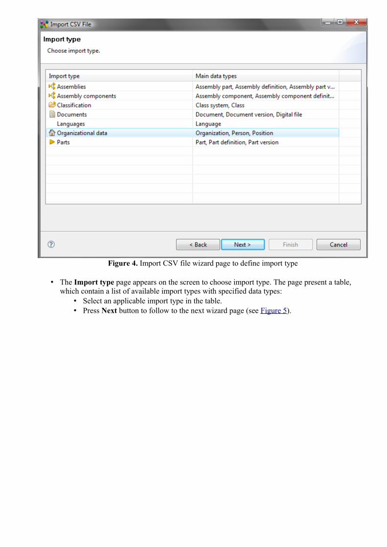
Figure 4. Import CSV file wizard page to define import type
• The Import type page appears on the screen to choose import type. The page present a table, which contain a list of available import types with specified data types:
• Select an applicable import type in the table. • Press Next button to follow to the next wizard page (see Figure 5).

Figure 5. Import CSV file wizard page to define column values
• The Define Column Values page appears on the screen to choose templates for columns to indicate the meaning of a column value:
• Import configuration field contains a name of selected configuration. If a new configuration was selected in the Import configuration page, you can save this configuration by clicking Save button. Specify a name and description of the configuration in the appeared wizard page. If you've edited the existing configuration, you can save it with a different name by clicking on the arrow next to the Save button and selecting Save as item.
• Import type field presents the selected import type. • Select a column in the Column drop down list. • Press Choose button next to the Column value type field to define the column template.
The Choose template wizard appears on the screen (see Figure 6):

Figure 6. Choose template wizard page
• Select a data role in the Role drop down list. The listed values depends on the import type, selected in the previous steps.
• Select a template value from the list below the Role field. • Press Next button to follow to the next Choose template wizard page (see Figure
7).
Figure 7. Column template parameters
• Enter needed parameters for the selected column template. In our example the template has no additional parameters, so the page is empty.
• Press Finish button. The selected template is assigned to the particular column (see Figure 8). You can review results in the Preview layout (Define Column Values page):
• Column header - column index in CSV file, Data role and template.

• Column value - value from the CSV file.
Figure 8. Assigned templates to the columns
• Import Parameters Template in the Define Column Values page (see Figure 5) presents a list of additional import parameters:
• Press Add button add new parameters and assign the constant value.The Add parameter wizard page appears (see Figure 9):
Figure 9. Add parameter wizard page
• Select a role of the parameter template in the Role drop down list. • Select an applicable attribute from the list below the Role field. • Press Next button. A new wizard page appears to enter parameter value (see
Figure 10). If another template is selected, an additional page may appear to defined needed parameters.

Figure 10. Add parameter wizard page to enter parameter value
• Enter an applicable parameter value into the Value field. • Press Finish button. The defined parameter with entered value appears in
the Import parameters layout table (see Figure 11).
Figure 11. Define Column Values wizard page, Import parameters layout
• Press Next button to follow to the next Import CSV File wizard page (see Figure 12). The Measure Units page appears on the screen to define measure units.
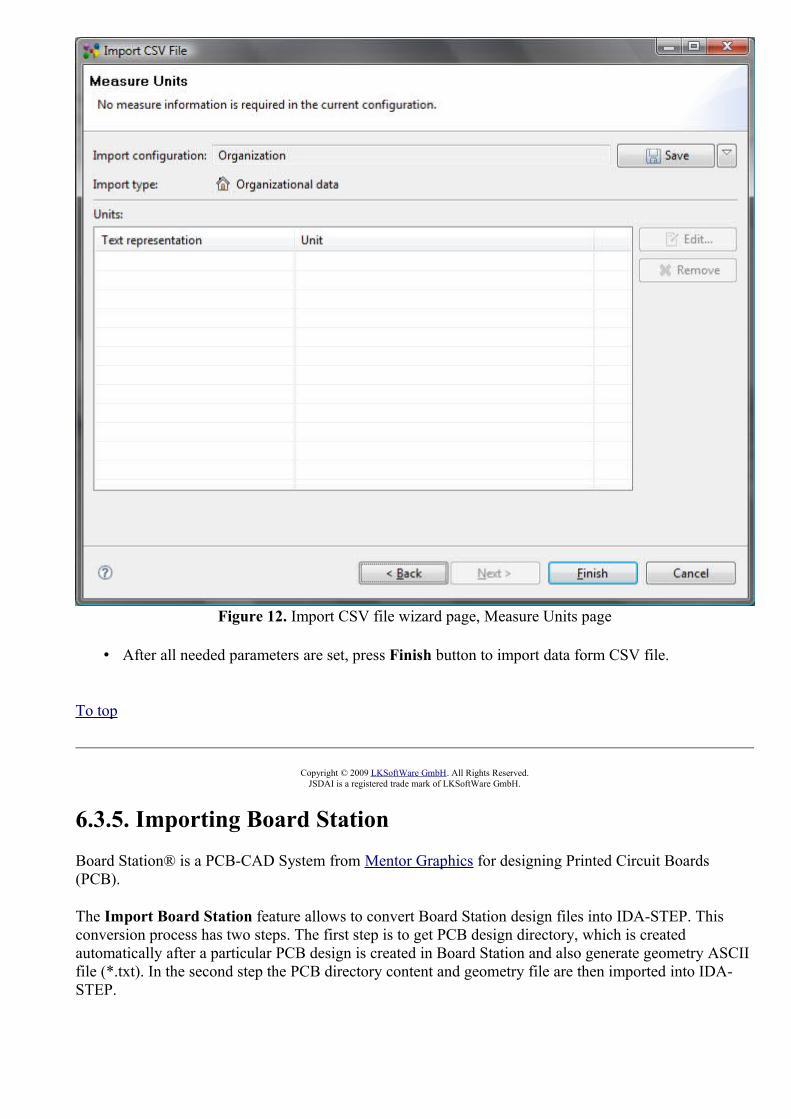
Figure 12. Import CSV file wizard page, Measure Units page
• After all needed parameters are set, press Finish button to import data form CSV file.
To top
Copyright © 2009 LKSoftWare GmbH. All Rights Reserved.JSDAI is a registered trade mark of LKSoftWare GmbH.
6.3.5. Importing Board StationBoard Station® is a PCB-CAD System from Mentor Graphics for designing Printed Circuit Boards (PCB).
The Import Board Station feature allows to convert Board Station design files into IDA-STEP. This conversion process has two steps. The first step is to get PCB design directory, which is created automatically after a particular PCB design is created in Board Station and also generate geometry ASCII file (*.txt). In the second step the PCB directory content and geometry file are then imported into IDA-STEP.

First step: Data preparation in Board Station
Start Mentor Board Station to get the following data, needed for the import to IDA-STEP:
• PCB directory, • ASCII geometry file.
Create/load an applicable PCB design project in Mentor Board Station. Automatically the particular PCB design directory is created inside the project (if a new project was created, in other way this directory must already be present in the project). After that you need to generate geometry file in ASCII (*.txt) format. This file must be created using Save ASCII geoms command (for more details read Mentor BoardStationTM manual). Note. This geometry file may be named arbitrary.
Second step: Import PCB directory and geometry ASCII file into IA-STEP
Follow the routine to import Board Station PCB and Printed Circuit Assembly (PCA) data into IDA-STEP:
• Select in the main menu File -> Import.• Select Electronics -> Board Station item in the appeared Import wizard page. The Import
Board Station wizard page appears on the screen (see Figure 1):
Figure 1. Import Board Station wizard page
• Locate a path of a PCB directory in Mentor BordStationTM project in the PCB Directory field by using Browse button.
• Locate a path to a ASCII geometry file in the ASCII Geometry File field. If this file is present in the recently selected PCB directory, the path of this file is located automatically into the ASCII Geometry File field.
• Press Finish button to confirm your selections and start import.
After the import is completed, the generated data are opened in IDA-STEP (see Figure 2). Ensure that the PCB/PCA perspective is selected.

Figure 2. Imported PCB and PCA data in the PCB/PCA Perspective
To top
Copyright © 2007-2009 LKSoftWare GmbH. All Rights Reserved.JSDAI is a registered trade mark of LKSoftWare GmbH.
6.3.6.1. Importing AllegroAllegro™ PCB Editor is a PCB layout system from Cadence Design Systems used to design Printed Circuit Boards (PCB). The Import Allegro feature allows to convert Allegro board files (*.brd) into IDA-STEP. This conversion process has two steps. The first step is to run a special extracta command inside Allegro PCB Editor to dump out ASCII files. In the second step these files are then imported into IDA-STEP. See Import Allegro for details on supported features.
First step: Data preparation in Allegro PCB Editor
Start Allegro PCB Editor and load board (*.brd) file to generate Allegro ASCII files (*.txt).The ASCII text files have to be generated by using extracta command (refer Allegro PCB Editor User Guide for details). The specific script file, named lksoft_allegro_extract.txt, should be used while performing extracta command. This file is located in the config folder, included in IDA-STEP installation folder (../plugins/net.jsdai.xim.ap210.allegro_*/config). The exact number ( 7) of names of

the files to be generated, have to be specified while running the script. Note: You can specify any names for these files.The order of files to be generated according the content:
1. Component, 2. Pins, 3. Pads, 4. Geometry, 5. Layers, 6. Nets, 7. Connectivity.
The Allegro ASCII text files of one design, should be located in a particular folder.
Second step: Import *.txt files into IDA-STEP
Follow the routine to import Allegro ASCII text files:
• Select File -> Import menu item in the main menu. • Select Import Allegro item in the appeared Import wizard dialog window. The Import
Allegro wizard dialog window is invoked to select data folder (see Figure 1).
Figure 1. Import Allegro wizard dialog window
• Select a folder in the file system containing Allegro ASCII text files by using Browse button next to the Data folder field. Note: The folder must contain the ASCII text files of only one design.
• Choose whether the complete design PCA and PCB is imported, or import PCA data only by selecting/unselecting Import PCA data only option.
• Details on how Allegro data is converted into STEP are defined in special configuration files, which are provided by LKSoft. Available configurations are listed in the Configuration list. Typically the Default configuration is used.

• Click Finish button to start the import process.
After an import is completed, you can see the log details of the import (a path to the source folder, an import duration, a path to the log file) in the Log view, which is opened in the following way:
• Select Window --> Show view --> Other in the main menu. The Show view dialog window appears.
• Select Other --> Log item. The Log view appears on the screen (see Figure 2).
Figure 2. Log view
To view imported data in IDA-STEP (see Figure 3) use the PCB/PCA perspective (select Window--> Open Perspective --> Other --> PCB/PCA).

Figure 3. Imported Allegro data in IDA-STEP
To top
Copyright © 2007-2009 LKSoftWare GmbH. All Rights Reserved.JSDAI is a registered trade mark of LKSoftWare GmbH.
6.3.6.2. Importing Example DataFollow the routine to import example Allegro ASCII text files:
• Start Import wizard by selecting File --> Import in the main menu. • Select Import Allegro item in the appeared layout. The second Import wizard dialog window
appears to select data folder. • Click Browse button to locate the folder. Browse to the IDA-STEP installation folder, enter into
.../plugins/net.jsdai.xim.ap210.allegro.imp.example folder, select cds_routed folder (see Figure 1). • The selected folder name appears in the Folder field.

Figure 1. cds_routed folder with Allegro ASCII text files
• Click OK button to confirm the selection. • A path to the selected data folder appears in the Data source field (see Figure 2).
Figure 2. Import Allegro wizard dialog with a specified path to the data folder
• Choose whether the complete design PCA and PCB is imported, or import PCA data only by selecting/unselecting Import PCA data only option.
• Details on how Allegro data is converted into STEP are defined in special configuration files, which are provided by LKSoft. Available configurations are listed in the Configuration list. Typically the Default configuration is used.
• Click Finish button to import data.
To view imported data use the PCB/PCA perspective (select Window--> Open Perspective --> Other --> PCB/PCA).

To top
Copyright © 2007-2009 LKSoftWare GmbH. All Rights Reserved.JSDAI is a registered trade mark of LKSoftWare GmbH.
6.3.7. Importing CircuitCAMLPKF CircuitCAM PCB is a CAM system from LKSoft / LPKF Laser & Electronics AG, which is used for designing Printed Circuit Boards (PCB).The Import CircuitCAM feature allows to convert CircuitCAM files (*.cam) into IDA-STEP. This conversion process has two steps. The first step is to make an auxiliary XML design file. In the second step these files are then imported into IDA-STEP. See Import CircuiCAM for details on supported features.
First step: Auxiliary XML file creation
You need to specify auxiliary (further we will use name AUX) file in order to import CircuitCAM designs into IDA-STEP.
See below a sample AUX file . This file, named info.xml, can be found in IDA-STEP installation folder (.../plugins/net.jsdai.xim.ap210.ccam/config): <?xml version="1.0" encoding="UTF-8" ?> - <design_info layout="Main">- <stratum_stack> <stratum name="s01" template="soldermask" level="s01" thickness="200" /> <stratum name="l01" template="electrical" level="l01" thickness="35" /> <stratum name="dielectric1" template="dielectric" thickness="1000" /> <stratum name="l02" template="electrical" level="l02" thickness="35" /> <stratum name="s02" template="soldermask" level="s02" thickness="200" /> </stratum_stack> <board_outline level="BoardOutline" /> </design_info>
In essence AUX file is a special XML file, that contains:
1. identification of CircuitCAM layout that contains design information; 2. mapping between CircuitCAM levels and IDA-STEP stratums; 3. identification of CircuitCAM level that contains board outline information.
Populate an AUX file for a new design by editing the sample AUX file. In order to specify (1) you need to edit layout attribute of design_info element. In most cases a name for a layout, containing design information, is Main and this is exactly what is specified in the sample AUX file. Here is the appropriate snippet of AUX file: <design_info layout="Main"> In order to specify (2) you need to edit stratum_stack element. This element contains a list of information for each stratum in the design. Each stratum is represented by stratum element. This element has four attributes:
• name - this mandatory attribute specifies a name of a stratum. In most cases this name is the same as a name of an appropriate level in CircuitCAM;Note. The value of this attribute should be unique.
• template - this mandatory attribute specifies a type of a stratum. Currently CircuitCAM IDA-STEP importer supports three types of stratums:
• electrical - a stratum, containing circuit geometry;

• soldermask - a stratum, containing solder-mask geometry; • dielectric stratum should contain no stratum and is present in stratum stack to represent
dielectric/core material. • level - this optional attribute specifies a name of a CircuitCAM level, which geometry will be used
for this stratum. Note, it is illegal to specify a level for dielectric stratums; • thickness - this optional attribute specifies a stratum's thickness in micro meters. If it is not
provided, then the default thickness of 0.1 mm is used.
Here is the appropriate snippet of AUX file: <stratum_stack> <stratum name="s01" template="soldermask" level="s01" thickness="200" /> <stratum name="l01" template="electrical" level="l01" thickness="35" /> <stratum name="dielectric1" template="dielectric" thickness="1000" /> <stratum name="l02" template="electrical" level="l02" thickness="35" /> <stratum name="s02" template="soldermask" level="s02" thickness="200" /> </stratum_stack>This snippet specifies the stratum stack consisting of 5 stratums. Note, it is important to specify stratums in the correct order going from the top to the bottom of a board. The top solder-mask stratum s01 uses the geometry from the level s01. The bottom solder-mask stratum s02 uses the geometry from the level s02. The top circuit/electrical stratum l01 uses the geometry from the level l01. The bottom circuit/electrical stratum l02 uses the geometry from the level l02. The stratum dielectric1 has no geometry and represents the core of PCB. Note, currently it is impossible to specify a thickness for a stratum and as a result the CircuitCAM IDA-STEP importer uses the default thicknesses (0.1 mm). This issue will be addressed in the upcoming release by allowing the user to specify a new thickness attribute for a stratum.
In order to specify (3) you need to edit a level attribute of the board_outline element. Here is an appropriate snippet of the AUX file specifying the BoardOutline level as the source for the board outline geometry: <board_outline level="BoardOutline" />
Additionally it is recommended to perform the union operation for the geometry in each CircuitCAM level before importing CircuitCAM file into IDA-STEP. This would provide much better final result when converting geometry to 3D.
Second step: Import *.cam and *.xml files into IDA-STEP
Follow the routine to import CircuitCAM PCB design data into IDA-STEP:
• Select in the main menu File -> Import.• Select Electronics -> CircuitCAM item in the appeared Import wizard page. The Import
CircuitCAM wizard page appears on the screen (see Figure 1):

Figure 1. Import CircuitCAM wizard page
• Locate a path to a CAM file in the Data file field by using Browse button. • Locate a path to an auxiliary XML file in the Auxiliary design file field by using Browse button. • Details on how CircuitCAM data is converted into STEP are defined in special configuration files,
which are provided by LKSoft. Available configurations are listed in the Configuration list. Typically the Default configuration is used.
• Press Finish button to import selected data.
After the import is completed, the generated data are opened in the IDA-STEP (see Figure 2). Ensure that the PCB/PCA perspective is selected.

Figure 2. Imported CircuitCAM PCB data in IDA-STEP
To top
Copyright © 2009 LKSoftWare GmbH. All Rights Reserved.JSDAI is a registered trade mark of LKSoftWare GmbH.
6.3.8. Importing PADSPADS® is a PCB-CAD System from Mentor Graphics for designing Printed Circuit Boards (PCB). The Import PADS wizard allows to import design from PADS data files (*.asc) into IDA-STEP. It requires the PADS ASCII data files (*.asc) to import data. Note. While exporting data from PADS Layout® to ASCII (*.asc) file, make sure you have selected to export all available data from the PADS design to PADS ASCII file.Follow the routine to import PADS design data into IDA-STEP:
• Select in the main menu File -> Import.• Select Electronics -> PADS item in the appeared Import wizard page. The Import PADS
wizard page appears on the screen (see Figure 1):

Figure 1. Import PADS wizard page
• Locate a path to an ASC file in the Data file field by using Browse button. • Details on how EAGLE data is converted into STEP are defined in special configuration
files, which are provided by LKSoft. Available configurations are listed in the Configuration list. Typically the Default configuration is used.
• Press Finish button to import selected data.
After the import is completed, the generated data are opened in the IDA-STEP (see Figure 2). Ensure that the PCB/PCA perspective is selected.

Figure 2. Imported PADS data (PCA and PCB) in IDA-STEP
To top
Copyright © 2007-2009 LKSoftWare GmbH. All Rights Reserved.JSDAI is a registered trade mark of LKSoftWare GmbH.
6.3.9. Importing CR-5000CR-5000 is Zuken's printed circuit board (PCB) and advanced packaging layout suite of customizable tools aimed at the Enterprise market. The Import CR-5000 wizard allows to import CR-5000 design into IDA-STEP. It requires the following data from CR-5000:
• PCB ASCII File (PCF extension) - the ASCII file describing the contents of the PCB Database;• Footprint ASCII File (FTF extension) - the ASCII file describing the contents of the Footprint
Library.
Follow the routine to import CR-5000 PCB and Printed Circuit Assembly (PCA) data into IDA-STEP:
• Select in the main menu File -> Import.• Select Electronics -> CR-5000 item in the appeared Import wizard page. The Import CR-
5000 wizard page appears on the screen (see Figure 1):

Figure 1. Importing CR-5000 wizard page
• Locate a path to a PCF file in the CR-5000 layout file field by using Browse button. • Locate a path to a FTF file in the CR-5000 footprint file field by using Browse button. • Locate a path to a log (TXT) file in the Log file field by using Browse button. This file will
contain the import log output. The short import log will be available in the Log view. • Choose whether the complete design PCA and PCB is imported, or import PCA data only
by selecting/unselecting Import PCA data only option. • Select the option Verbose logging mode to get more detailed information in the log file. • Details on how CR-5000 data is converted into STEP are defined in special configuration
files, which are provided by LKSoft. Available configurations are listed in the Configuration list. Typically the Default configuration is used.
• Press Finish button to import selected data.
After the import is completed, the generated data are opened in the IDA-STEP (see Figure 2). Ensure that the PCB/PCA perspective is selected.

Figure 2. Imported CR-5000 data (PCB and PCA) to IDA-STEP
To top
Copyright © 2009 LKSoftWare GmbH. All Rights Reserved.JSDAI is a registered trade mark of LKSoftWare GmbH.
6.3.10. Importing ExpeditionExpedition™ is a PCB-CAD System from Mentor Graphics for designing Printed Circuit Boards (PCB). The Import Expedition wizard allows to import design from Expedition data files into IDA-STEP. It requires the Expedition PCB data folder with the following files, which can be find in one of the the Expedition PCB project folders:
• Cell.hkp, • JobPrefs.hkp, • Layout.hkp, • NetClass.hkp, • NetProps.hkp, • Padstack.hkp, • PDB.hkp.
Follow the routine to import Expedition PCB and Printed Circuit Assembly (PCA) data into IDA-STEP:
• Select in the main menu File -> Import.• Select Electronics -> Expedition item in the appeared Import wizard page. The Import

Expedition wizard page appears on the screen (see Figure 1):
Figure 1. Import Expedition wizard page
• Locate a path to the Expedition folder in the Data directory field by using Browse button. • Choose whether the complete design PCA and PCB is imported, or import PCA data only
by selecting/unselecting Import PCA data only option. • Select the option Verbose logging mode to get more detailed information in the LOG file. • Details on how Expedition data is converted into STEP are defined in special configuration
files, which are provided by LKSoft. Available configurations are listed in the Configuration list. Typically the Default configuration is used.
• Press Finish button to import selected data.
After the import is completed, the generated data are opened in the IDA-STEP (see Figure 2). Ensure that the PCB/PCA perspective is selected.

Figure 2. Imported Expedition data in IDA-STEP
To top
Copyright © 2007-2009 LKSoftWare GmbH. All Rights Reserved.JSDAI is a registered trade mark of LKSoftWare GmbH.
6.3.11. Importing CADIFCADIF (*.paf) is an ASCII neutral file, which is used for storing PCB, PCA and other information. This file is used by ECAD systems CR-5000, VISULA and CADSTAR from Zuken.The Import CADIF feature allows to import design stored in CADIF file into IDA-STEP. It requires only the CADIF (*.paf) file.Follow the routine to import CADIF PCB and Printed Circuit Assembly (PCA) data into IDA-STEP:
• Select in the main menu File -> Import.• Select Electronics -> CADIF item in the appeared Import wizard page. The Import CADIF
wizard page appears on the screen (see Figure 1):

Figure 1. Import CADIF wizard page
• Locate a path to a PAF file in the Data file field by using Browse button. • Choose whether the complete design PCA and PCB is imported, or import PCA data only
by selecting/unselecting Import PCA data only option. • Select the option Verbose logging mode to get more detailed information in the LOG file. • Appropriate configuration needs to be chosen in the Configurations layout depending on
whether imperial or metric units are used for attributes (e.g. height attribute for packages) in CADIF file.
• Press Finish button to confirm your selections and start import.
After the import is completed, the generated data are opened in the IDA-STEP (see Figure 2). Ensure that the PCB/PCA perspective is selected.

Figure 2. Imported CADIF data (PCB and PCA) to IDA-STEP
To top
Copyright © 2007-2009 LKSoftWare GmbH. All Rights Reserved.JSDAI is a registered trade mark of LKSoftWare GmbH.
6.4.1. Export WizardThe Export wizard helps to extract or convert data out of IDA-STEP (see Figure 1) into formats other than XIM (for more information on XIM reference http://www.jsdai.net/xim). To start the Export wizard select in IDA-STEP main menu bar File -> Export.

Figure 1. Export wizard page
When the Export wizard page appears on the screen you must select what type of export to do. To assist in locating a particular wizard, the text field can be used to show only the wizards that match the entered text. After an export type is selected, click Next button to launch a particular wizard page.
To top
Copyright © 2009 LKSoftWare GmbH. All Rights Reserved.JSDAI is a registered trade mark of LKSoftWare GmbH.
6.4.3. STEP: 2D PCA/PCB data extruded to 3D The STEP: 2D PCA/PCB data extruded to 3D export allows to generate 3D shape for the selected PCA/PCB and export it as AP203 STEP file. This STEP file can then be opened by almost any mechanical CAD system. The generated STEP file contains not only PCA/PCB 3D shape, but also it's assembly structure.Follow the routine to export an applicable PCA/PCB design to the AP203 STEP file:
• A particular PCA/PCB design has to be opened or imported in IDA-STEP (see Figure 1).

Figure 1. Opened STEP file with PCA and PCB design data and 2D view
• Select in the main menu File -> Export. The Export wizard appears on the screen. • Select Electronics -> STEP: 2D PCA/PCB data extruded to 3D item and press the Next
button on the bottom section of the wizard page. • The Export 3D PCA/PCB Extrusion wizard page appears (see Figure 2):

Figure 2. Export 3D PCA/PCB Extrusion wizard page
• Click Browse button next to the File field to locate the target STEP file in your file system. • Select an applicable data output format AP214 or 203ed2 by selecting a value in the
Output format drop down list. • To generate 3D shape for PCA using "real" (not simply extruded) 3D package shapes,
select which package library to use (if any) when generating PCA 3D shape in the E-CAD to M-CAD Mapping Set drop down list. How to manage the E-CAD to M-CAD Mapping library, refer clause E-CAD to M-CAD Mapping.
• Enter an applicable number value into the Default PCB height field - the PCB height that will be used for 3D shape generation if there is no data about PCB height in the design or the height data in the design is less than specified in this field..
• Enter an applicable number value into the Default package height field - the package height that will be used for 3D shape generation if there is no data about package height in
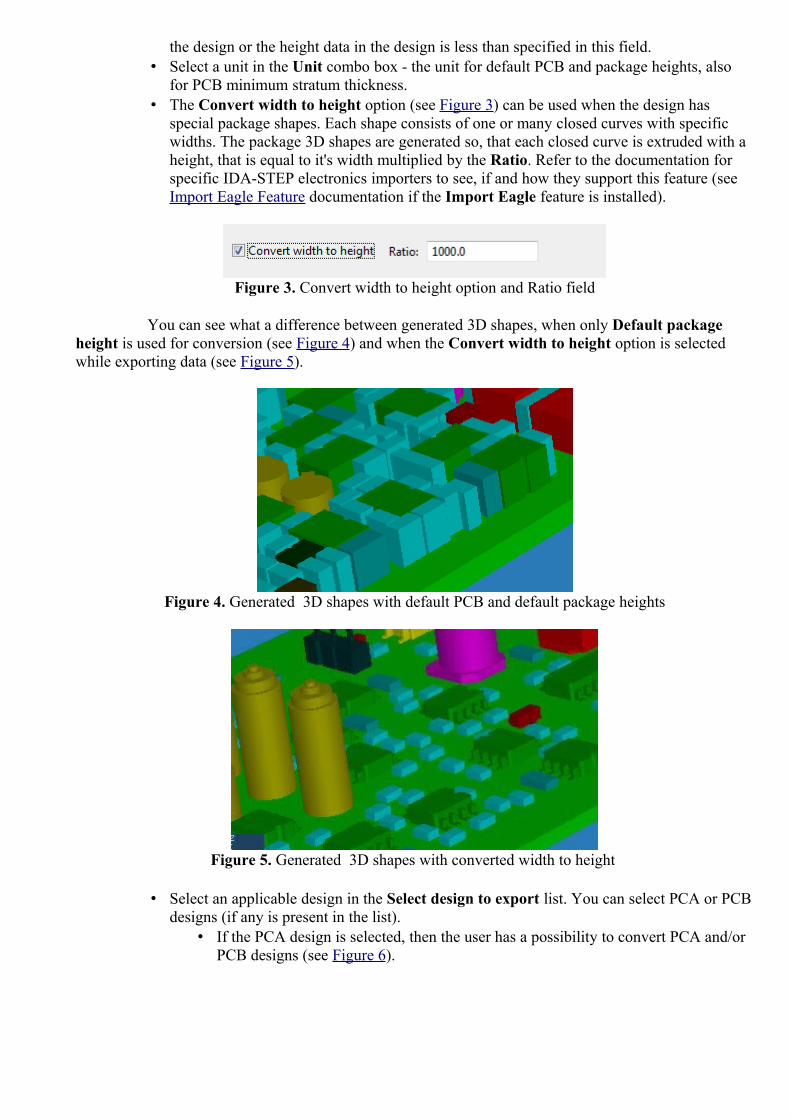
the design or the height data in the design is less than specified in this field.• Select a unit in the Unit combo box - the unit for default PCB and package heights, also
for PCB minimum stratum thickness.• The Convert width to height option (see Figure 3) can be used when the design has
special package shapes. Each shape consists of one or many closed curves with specific widths. The package 3D shapes are generated so, that each closed curve is extruded with a height, that is equal to it's width multiplied by the Ratio. Refer to the documentation for specific IDA-STEP electronics importers to see, if and how they support this feature (see Import Eagle Feature documentation if the Import Eagle feature is installed).
Figure 3. Convert width to height option and Ratio field
You can see what a difference between generated 3D shapes, when only Default package height is used for conversion (see Figure 4) and when the Convert width to height option is selected while exporting data (see Figure 5).
Figure 4. Generated 3D shapes with default PCB and default package heights
Figure 5. Generated 3D shapes with converted width to height
• Select an applicable design in the Select design to export list. You can select PCA or PCB designs (if any is present in the list).
• If the PCA design is selected, then the user has a possibility to convert PCA and/or PCB designs (see Figure 6).

Figure 6. PCA and PCB 3D view
In Figure 2 it is selected the PCA design. You can see the enabled check box Convert PCB details. If this check box is not selected, than only PCA details should be converted (see Figure 7).
Figure 7. PCA design 3D view
• If PCB design is selected - only PCB data will be converted to 3D (see Figure 8):

Figure 8. PCB design 3D view
• The Convert PCB details check box is selected automatically (see Figure 9). Options in the PCB Details layout are enabled for selection. You can select applicable PCB details to be converted:
Figure 9. Convert PCB details
• Select Convert Passages check box to convert passages. • Enter a number value of the minimum stratum thickness that will be used
for 3D shape generation into the Minimum stratum thickness field. This value is used, if no minimum stratum thickness data is present in the selected design or the value in the design is smaller then the currently entered value.
• Select applicable stratums to be converted: • Outer Electrical stratums - the stratums are selected
automatically: outer stratums - with details ( check box icon) and stratums between them - without details ( check box icon).
• Select Stratum option allows to select all available stratums and their representation (see Figure 10). Select this radio button in order

to add more needed stratums to be converted:
Figure 10. Select Stratums
• The list of available stratums is enabled for selection. The representation of each stratum can be selected by clicking on the check box in front of the particular stratum:
• "unselected" check box icon - the stratum is not selected for converting.
• "partially selected"check box icon - a stratum without details (see Figure 11 ).
Figure 11. Converted stratum converted without details
• "fully selected" check box icon - a stratum with details (see Figure 12 - the same stratum as in Figure 11).
Figure 12. Stratum converted with details

• Click Finish to confirm your selections and start export. After the export is completed, the wizard page is closed automatically. The specified target STEP file appears in the specified location.
To top
Copyright © 2009 LKSoftWare GmbH. All Rights Reserved.JSDAI is a registered trade mark of LKSoftWare GmbH.
6.4.4. Exporting STEP (ISO 10303 - part 21)STEP-File is the most widely used data exchange form of STEP (Standard for the Exchange of Product model data). Due to its ASCII structure it is easy to read with typically one instance per line. The format of a STEP-File is defined in ISO 10303-21 Clear Text Encoding of the Exchange Structure.
ISO 10303-21 defines the encoding mechanism on how to represent data according to a given EXPRESS schema, but not the EXPRESS schema itself. STEP-File are also called p21-File and STEP Physical File. The file extensions .stp and .step indicate that the file contain data conforming to STEP Application Protocols. For more information on STEP file reference http://en.wikipedia.org/wiki/ISO_10303-21.
Follow the routine to export STEP data:
• Applicable STEP data have to be loaded in IDA-STEP. • Select in the main menu File -> Export. The Export wizard appears on the screen:
• Select Other -> STEP (ISO 10303 - part 21) item and press Next button. • The Export STEP wizard dialogue window appears on the screen (see Figure 1):
Figure 1. Export STEP dialogue window
• Select an applicable Application Protocol (AP) in the Select export AP layout: • AP203 ed2 Only - export STEP data according AP203 ed2 (Configuration
controlled 3D designs of mechanical parts and assemblies) format; • AP210 Only - export STEP data according AP210 (Electronic assembly,

interconnection, and packaging design) format; • AP214 Only - export STEP data according AP214 (Core data for
automotive mechanical design processes) format; • AP239 Only - export STEP data according AP239 (Product life cycle
support) format; • AP242 Only - export STEP data according AP242 (Managed Model-Based
3D Engineering) format;• Cross-AP - export data as it is, independent of a particular AP.
• Select a destination file by using Browse button next to the File field. • Press Finish button.
To top
Copyright © 2009-2011 LKSoftWare GmbH. All Rights Reserved.JSDAI is a registered trade mark of LKSoftWare GmbH.
6.4.5. Exporting to CSVThe Export to CVS tool generates the CSV (Comma Separated Values) file, which is a format supported by most applications (e.g. Microsoft Excel). Follow the routine to export the currently opened STEP file data to a CSV file:
• A particular data have to be opened/imported into IDA-STEP (see Figure 1).
Figure 1. STEP file with data opened in IDA-STEP

• Select in the main menu File -> Export. The Export wizard appears on the screen. • Select Text -> CSV (Comma Separated Values) item in the list. • The Export view to set export settings and select which view to export appears on the screen (see
Figure 2):
Figure 2. Export to CSV wizard window
• Select the Write header to CSV file check box to add a header for the table to be generated (see Figure 3).
Figure 3. Generated CSV file table with header
• Select an applicable separator character in the Separator layout by selecting a particular radio button:
• Tab - the text in the generated table should be separated by tab character; • Semicolon - the text in the generated table should be separated by column character
(see Figure 4);

Figure 4. The text separator semicolon (';')
• Comma - the text in the generated table should be separated by comma character; • Space - the text in the generated table should be separated by space character; • Other - if this radio button is selected, enter an applicable character into the text
field; • Text delimiter - select an applicable value from the drop down list.
• Select one of available views, which data should be exported to CSV file in the Views layout.
• Click Browse button next to the File field to locate the target CSV file in your file system. • You can select an applicable File encoding value in the drop down list. • Press Finish button to confirm your selections and start export. After the export is
completed, the wizard page is closed automatically. The specified target CSV file appears in the specified location.
To top
Copyright © 2008-2009 LKSoftWare GmbH. All Rights Reserved.JSDAI is a registered trade mark of LKSoftWare GmbH.
6.4.6. Exporting to STLThe Export to STL tool generates binary .stl (stereolitography) file. STL files describe only the surface geometry of a three dimensional object without any representation of colour, texture or other common CAD model attributes.Follow the routine to export the currently opened STEP file data to a STL file:
• The STEP file with an applicable 3D model data has to be opened in IDA-STEP (see Figure 1).

Figure 1. STEP file with 3D model data
• Select in the main menu File -> Export. The Export wizard appears on the screen: • Select Other -> Export STL item. • The Export STL wizard page appears to locate the file to be created (see Figure 2):
Figure 2. Export STL wizard page to locate stl file
• Click Browse button next to the File field to locate the STL file in your file system. After the export is finished, the specified STL file appears in the selected location.
• Click Finish button to confirm your selection and start export. After the export is completed the wizard page is closed automatically. The created STL file is available in the specified location.
To top

Copyright © 2011 LKSoftWare GmbH. All Rights Reserved.JSDAI is a registered trade mark of LKSoftWare GmbH.
6.4.7. Exporting to VRMLThe Export to VRML tool generates .wrl file (virtual world created in VRML (Virtual Reality Modeling Language-97) version 2.0), which can be navigated in three dimensions, contains coordinates and colours that define each object and shape; also includes the viewpoint coordinates for the initial view of the 3D scene.Follow the routine to export the currently opened STEP file data to a WRL file:
• The STEP file with an applicable 3D model data has to be opened in IDA-STEP (see Figure 1).
Figure 1. STEP file with 3D model data
• Select in the main menu File -> Export. The Export wizard appears on the screen: • Select Other -> Export VRML item. • The Export VRML wizard page appears to locate the file to be created (see Figure 2):

Figure 2. Export VRML wizard to locate wrl file
• Click Browse button next to the File field to locate the WRL file in your file system. After the export is finished, the specified WRL file appears in the selected location.
• Click Finish button to confirm your selection and start export. After the export is completed the wizard page is closed automatically. The created WRL file is available in the specified location.
To top
Copyright © 2011 LKSoftWare GmbH. All Rights Reserved.JSDAI is a registered trade mark of LKSoftWare GmbH.
6.4.8. Exporting CircuitCAMComputer Aided Manufacturing (CAM) files, also known as Gerbers or Gerber files, are the standard format for describing your board design.
Follow the routine to export the PCB design data to CAM file:
• The STEP file with the desired PCB data has to be opened in the IDA-STEP (see Figure 1).
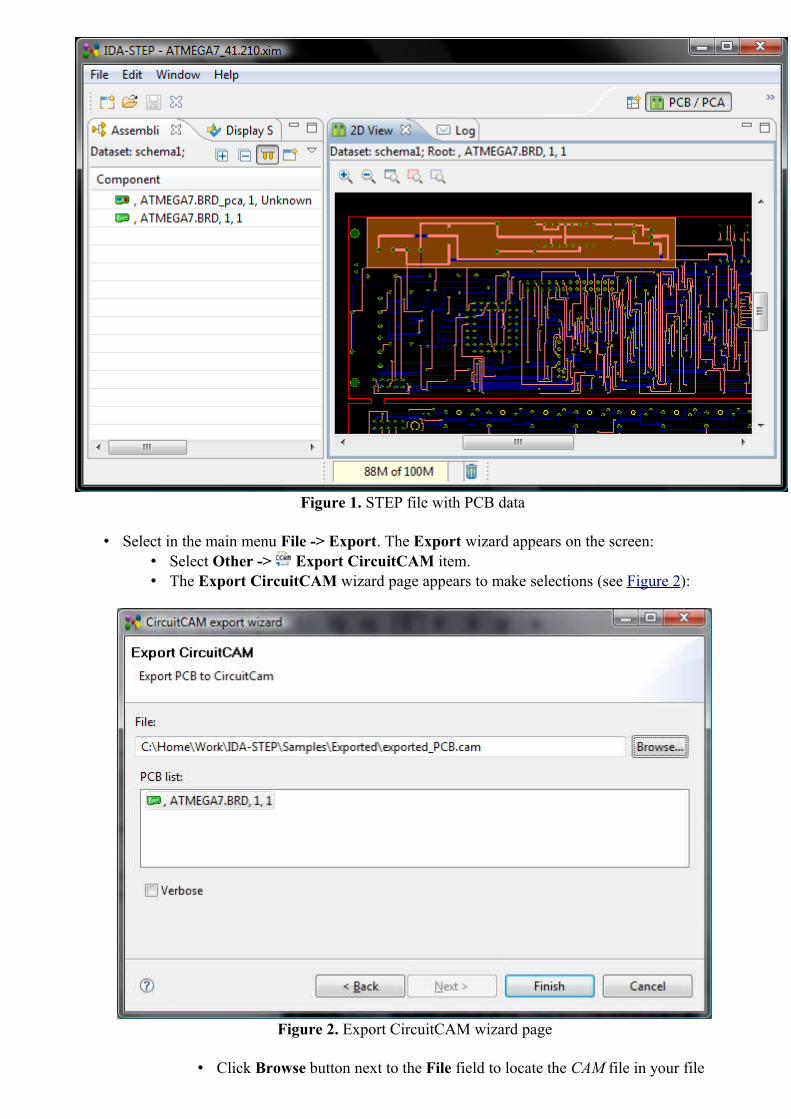
Figure 1. STEP file with PCB data
• Select in the main menu File -> Export. The Export wizard appears on the screen: • Select Other -> Export CircuitCAM item. • The Export CircuitCAM wizard page appears to make selections (see Figure 2):
Figure 2. Export CircuitCAM wizard page
• Click Browse button next to the File field to locate the CAM file in your file
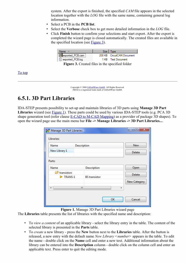
system. After the export is finished, the specified CAM file appears in the selected location together with the LOG file with the same name, containing general log information.
• Select a PCB in the PCB list. • Select the Verbose check box to get more detailed information in the LOG file. • Click Finish button to confirm your selections and start export. After the export is
completed the wizard page is closed automatically. The created files are available in the specified location (see Figure 3).
Figure 3. Created files in the specified folder
To top
Copyright © 2008 LKSoftWare GmbH. All Rights Reserved.JSDAI is a registered trade mark of LKSoftWare GmbH.
6.5.1. 3D Part LibrariesIDA-STEP presents possibility to set-up and maintain libraries of 3D parts using Manage 3D Part Libraries wizard (see Figure 1). These parts could be used by various IDA-STEP tools (e.g. PCA 3D shape generation tool (refer clause E-CAD to M-CAD Mapping) as a provider of package 3D shapes). To open the wizard page use the main menu bar File -> Manage Libraries -> 3D Part Libraries....
Figure 1. Manage 3D Part Libraries wizard pageThe Libraries table presents the list of libraries with the specified name and description:
• To view a content of an applicable library - select the library entry in the table. The content of the selected library is presented in the Parts table.
• To create a new library - press the New button next to the Libraries table. After the button is released, a new entry with the default name New Library <number> appears in the table. To edit the name - double click on the Name cell and enter a new text. Additional information about the library can be entered into the Description column - double click on the column cell and enter an applicable text. Press enter to quit the editing mode.

• To remove a redundant or an incorrect library entry - select a library entry in the table and press Delete button, located next to the table.
The Parts table presents the hierarchy of the selected library - 3D parts, which can be classified into particular categories. Each category and part are defined by a name and a description (optionally). See below, how to manipulate with data, presented in the Parts table:
• To open a 3D part data in a new IDA-STEP window:• Select an applicable part in the Parts table. • Press the Open button next to the table. A new IDA-STEP window appears on the screen
with loaded data of the selected part. • To create a new category - press the New Category button next to the Parts table. The New
Category dialogue window appears on the screen (see Figure 2):
Figure 2. New Category dialogue window with specified category name
• Enter a name, by which the category is known into the Name field. • Press the OK button. The created category appears in the Parts table.
Note. In case the created category appears under the another category node, you can move it to the upper level - press with the mouse on the category entry, hold and drag it to the upper level.
• To delete a redundant or an incorrect category - select a category entry in the table list and press the Delete button next to the table. Note. In case the deleted category was not empty, related parts are moved to the top level.
• To move parts to a category - select a part, press with a mouse button hold and drag to an applicable category.
After all changes are made in the Manage 3D Libraries wizard page, press the OK button to confirm changes and close the window. Note. Press the Cancel button to close the window without saving changes.
How to add parts to the library, see Add 3D Part to Library.
To top
Copyright © 2011 LKSoftWare GmbH. All Rights Reserved.JSDAI is a registered trade mark of LKSoftWare GmbH.
6.5.2. E-CAD to M-CAD MappingTo generate 3D shape for PCA using "real" (not simply extruded) 3D package shapes we need to have a 3D parts library (see 3D Part Libraries) and package library.
IDA-STEP present the Manage E-CAD to M-CAD Mapping wizard, which guides in the population of

package libraries (see Figure 1).
Figure 1. Manage E-CAD to M-CAD Mapping wizard page
The Mapping Sets table presents a list of package libraries (mapping sets), which are defined by Name, Description and associated 3D Part Library:
• To view a content of a mapping set - click with a mouse button on an applicable mapping set entry in the Mapping Sets table. The content of the selected mapping set is displayed in the Mapping table.
• To create a new package library: • Press on the New button next to the table. A New Mapping Set <number> entry appears in
the Name column. You can rename the created library name by double clicking on the Name column cell and entering a new text.
• You can enter additional information about the created mapping set into the Description cell (double click and enter an applicable text).
• Define 3D part library, which parts should be used for mapping: • Double click on the 3D Part Library cell and press the appeared look up button. • Select an applicable 3D part library in the Select 3D Part Library wizard page (see
Figure 2). You can filter out the particular library by entering the text into the filter field. Libraries, which names are close to the entered text, are displayed in the list. After the selection is done, press the OK button to confirm your choice and close the window. The selected 3D part library appears in the 3D Part Library column cell.

Figure 2. Select 3D Part Library wizard page
• To remove an incorrect or redundant mapping set - select a mapping set in the table and press the Delete button next to the table.
The Mapping table presents a list of packages (mappings), assigned for the selected package library (mapping set). The package object in package library should contain following attributes:
1. Package name - name, by which the package is known.2. Alternate name - mandatory and unique identification within the library.3. Height - the length measure with unit specifying the height to be used to generate extruded
package shape, if 3D shape is not provided; 4. 3D shape - the reference to a 3D part in 3D parts library to be used for this package in generated
PCA 3D shape. 5. Transformation - transformation data of the 3D part.
To create a new package object in the selected library:
• Press the New button next to the Mappings table. The New Mapping <number> entry appears in the Package Name column. You can change the created package name by double clicking on the Package Name column cell and entering a new text.
• Add a text into the Alternate Name column cell to define a unique identifier for the package. • Specify the height to be used to generate extruded package shape. Double click on the Height
column cell. Enter the value into the text field, and select the unit in the drop down list, which appears next to the text field.
• Select a 3D part in 3D parts library to be used for this package in generated PCA 3D shape. Double click on the 3D Part column cell. Press on the look up button. The Select 3D Part appears on the screen (see Figure 3):
• Expand branches (if any) and select an applicable part. • Press the OK button to confirm your selection and close the window. The selected 3D part
appears in the 3D Part column cell.
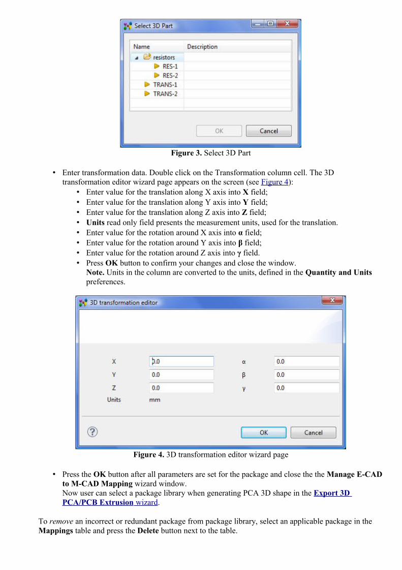
Figure 3. Select 3D Part
• Enter transformation data. Double click on the Transformation column cell. The 3D transformation editor wizard page appears on the screen (see Figure 4):
• Enter value for the translation along X axis into X field; • Enter value for the translation along Y axis into Y field; • Enter value for the translation along Z axis into Z field; • Units read only field presents the measurement units, used for the translation.• Enter value for the rotation around X axis into α field; • Enter value for the rotation around Y axis into β field; • Enter value for the rotation around Z axis into γ field. • Press OK button to confirm your changes and close the window.
Note. Units in the column are converted to the units, defined in the Quantity and Units preferences.
Figure 4. 3D transformation editor wizard page
• Press the OK button after all parameters are set for the package and close the the Manage E-CAD to M-CAD Mapping wizard window. Now user can select a package library when generating PCA 3D shape in the Export 3D PCA/PCB Extrusion wizard .
To remove an incorrect or redundant package from package library, select an applicable package in the Mappings table and press the Delete button next to the table.

To top
Copyright © 2011 LKSoftWare GmbH. All Rights Reserved.JSDAI is a registered trade mark of LKSoftWare GmbH.
6.6. LanguageThis feature is under construction.
There is a possibility to change the default language for data in IDA-STEP. Note. The default language can be selected in the preferences page (refer Clause Preferences -> General -> Language).Follow the routine to switch the language:
• Select in the main menu bar File -> Language. The Language dialogue window appears on the screen (see Figure 1). The currently applied language is displayed next to the label Current language.
Figure 1. Language dialogue window
• Select an applicable language in the Switch to combo box drop down list. • Press Finish button to confirm your sleection.
To top
Copyright © 2011 LKSoftWare GmbH. All Rights Reserved.JSDAI is a registered trade mark of LKSoftWare GmbH.
7. Installed FeaturesFor general information about installed features see the Overview page. Under this clause you will find introductions of all installed features.
The following features are currently installed:
• IDA-STEP Framework • Layer Stack Editor • GD&T Editor

• Import CR-5000 • Viewer Basic • Viewer Pro 3D • Import Allegro • Import Board Station • Import CADIF • Import CircuitCAM • Import EAGLE • Import Expedition • Import PADS • Electronics
To top
Copyright © 2009-2011 LKSoftWare GmbH. All Rights Reserved.JSDAI is a registered trade mark of LKSoftWare GmbH.
7.1. ElectronicsIDA-STEP Electronics focuses on ISO 10303-210 "Electronic Assembly Interconnect and packaging Design" (AP210). While the basic viewer component allows to view all aspects of AP210, the Electronics component has extended capabilities:
• Exporting to CSV File ; • Printing; • Exporting to CircuitCAM ; • Exporting to AP203: 2D PCA/PCB data Extruded to 3D ; • Dynamic columns.
To top
Copyright © 2009 LKSoftWare GmbH. All Rights Reserved.JSDAI is a registered trade mark of LKSoftWare GmbH.
7.2. GD&T EditorThe GD&T (Geometric Dimensioning and Tolerancing) Editor feature allows editing of of geometric dimensions and tolerances, assembly structures and other product information. The following data editing is available in IDA-STEP with installed GD&T Editor feature:
• Basic PDM editing: • Parts view: creating (part version, new version, classification system, classification,
class attribute), editing / copying and pasting data and etc..• Persons and Organizations view: creating new elements (organization, person and
position), copying and pasting, editing person, organization, position, address data and etc. • Document view: creating, editing and removing of document data.
• Product structure editing: • Part Details view: adding new components, editing, copying and pasting, removing
components. • Geometry Details view (geometric model details and editing):
• Construction Geometry Models: create model, style construction geometry elements.

• Geometric Models: style geometric model elements (visibility, colour, transparency), • Style/Annotation Models: create new style/annotation models, style annotations and
annotation occurrences (visibility, colour), • Presentation Models.
• GD&T editing: • shape aspects; • dimensions; • datum features, targets, • geometric tolerances and etc.
• Exporting STEP data. • Saving of XIM files.
To top
Copyright © 2010 LKSoftWare GmbH. All Rights Reserved.JSDAI is a registered trade mark of LKSoftWare GmbH.
7.3. IDA-STEP FrameworkIDA-STEP Framework feature handles the main aspects of the Graphical User Interface (GUI) and all aspects on registration, installation and update.
To top
Copyright © 2007-2009 LKSoftWare GmbH. All Rights Reserved.JSDAI is a registered trade mark of LKSoftWare GmbH.
7.4. Import AllegroCadence® Allegro® PCB Editor is a PCB layout system from Cadence Design Systems for designing Printed Circuit Boards (PCB).
The Import Allegro feature allows to convert Allegro board files (*.brd) into IDA-STEP. This conversion process has two steps. The first step is to run a special extracta command inside Allegro PCB Editor to dump out ASCII files. In the second step these files are then imported into IDA-STEP. Import feature uses the following Allegro design files from indicated Allegro data folder:
• ASCII layers file, • ASCII pads file, • ASCII components file, • ASCII geometry file, • ASCII nets file.
This feature imports the following PCB and Printed Circuit Assembly (PCA) data:
• detailed layout data of the bare PCB (layers, tracks, pads, physical nets, thickness, keep-out areas, board-outline, etc.);
• PCA layout data (assembly components with transformation, networks); • library information (parts, packages, lands, vias, etc.); • technology (Surface Mount Device (SMD), through hole, etc.); • full graphical information (2D).

User can choose whether the complete design PCA and PCB is imported, or Import PCA data only.
See Importing Allegro for details.
To top
Copyright © 2007-2009 LKSoftWare GmbH. All Rights Reserved.JSDAI is a registered trade mark of LKSoftWare GmbH.
7.5. Import BoardStationBoard Station® is a PCB-CAD System from Mentor Graphics for designing Printed Circuit Boards (PCB).
The Import Board Station feature allows to convert Board Station design files into IDA-STEP. This conversion process has two steps. The first step is to get PCB design directory, which is created automatically after a particular project is created in Board Station and also generate geometry ASCII file (*.txt). In the second step the PCB directory content and geometry file are then imported into IDA-STEP.
This feature imports the following PCB and Printed Circuit Assembly (PCA) data:
• detailed layout data of the bare PCB (layers, tracks, pads, physical nets, thickness, keep-out areas, board-outline, etc.);
• PCA layout data (assembly components with transformation, networks); • library information (parts, packages, lands, vias, etc.); • technology (Surface Mount Device (SMD), through hole, etc.); • full graphical information (2D).
See Importing Board Station for details.
To top
Copyright © 2007-2009 LKSoftWare GmbH. All Rights Reserved.JSDAI is a registered trade mark of LKSoftWare GmbH.
7.6. Import CADIFCADIF (*.paf) is an ASCII neutral file, which is used for storing PCB, PCA and other information. This file is used by ECAD systems CR-5000, VISULA and CADSTAR from Zuken.
The Import CADIF feature allows to import design stored in CADIF file into IDA-STEP. It requires only the CADIF (*.paf) file.
This feature imports the following PCB and Printed Circuit Assembly (PCA) data (it is possible to import PCA data only):
• detailed layout data of the bare PCB (layers, tracks, pads, physical nets, thickness, keep-out areas, board-outline, etc.);
• PCA layout data (assembly components with transformation, networks); • library information (parts, packages, lands, vias, etc.); • technology (Surface Mount Device (SMD), through hole, etc.); • full graphical information (2D).

User can choose whether the complete design PCA and PCB is imported, or Import PCA data only. See Importing CADIF for details
To top
Copyright © 2007-2009 LKSoftWare GmbH. All Rights Reserved.JSDAI is a registered trade mark of LKSoftWare GmbH.
7.7. Import CircuitCamLPKF CircuitCAM PCB is a CAM system from LKSoft / LPKF Laser & Electronics AG, which is used for designing Printed Circuit Boards (PCB).
LPKF CircuitCAM PCB software provides the user with a sophisticated CAM station. It can control all production data, modify the design, step and repeat the complete layout, perform different design rule checks, generate ground planes, input text using TrueType fonts, and generate routing data. LPKF CircuitCAM PCB is also a very efficient data converter, such as converting AutoCAD data to Gerber data.
The Import CircuitCAM feature allows to convert CircuitCAM files (*.cam) into IDA-STEP. This conversion process has two steps. The first step is to make an auxiliary XML design file. In the second step these files are then imported into IDA-STEP.
This feature imports the following PCB and Printed Circuit Assembly (PCA) data:
• detailed layout data of the bare PCB (layers, tracks, pads, physical nets, thickness, keep-out areas, board-outline, etc.);
• PCA layout data (assembly components with transformation, networks); • library information (parts, packages, lands, vias, etc.); • technology (Surface Mount Device (SMD), through hole, etc.); • full graphical information (2D).
See Importing CircuitCAM for more details.
To top
Copyright © 2007-2009 LKSoftWare GmbH. All Rights Reserved.JSDAI is a registered trade mark of LKSoftWare GmbH.
7.8. Import CR-5000 FeatureCR-5000 is Zuken's printed circuit board (PCB) and advanced packaging layout suite of customizable tools aimed at the Enterprise market. The Import CR-5000 feature allows to import CR-5000 design into IDA-STEP. It requires the following data from CR-5000:
• PCB ASCII File (PCF extension) - the ASCII file describing the contents of the PCB Database;• Footprint ASCII File (FTF extension) - the ASCII file describing the contents of the Footprint
Library.
This feature imports the following PCB and Printed Circuit Assembly (PCA) data (it is possible to import PCA data only):

• detailed layout data of the bare PCB (layers, tracks, pads, physical nets, thickness, keep-out areas, board-outline, etc.);
• PCA layout data (assembly components with transformation, networks); • library information (parts, packages, lands, vias, etc.); • technology (Surface Mount Device (SMD), through hole, etc.); • full graphical information (2D).
User can choose whether the complete design PCA and PCB is imported, or Import PCA data only. See Importing CR-5000 for more details.
To top
Copyright © 2009 LKSoftWare GmbH. All Rights Reserved.JSDAI is a registered trade mark of LKSoftWare GmbH.
7.9. Import EAGLEEAGLE Layout Editor is a tool from CadSoft for designing Printed Circuit Boards (PCB).The Import EAGLE feature allows to convert EAGLE board files (*.brd) into IDA-STEP. This conversion process has two steps. The first step is to run a special ULP program inside EAGLE to dump out the binary board file into an ASCII file and also to generate a design rule file (*.dru). In the second step these files are then imported into IDA-STEP.
This feature imports the following PCB and Printed Circuit Assembly (PCA) details:
• detailed layout data of the bare PCB (layers, tracks, pads, physical nets, thickness, keep-out areas, board-outline, etc.);
• PCA layout data (assembly components with transformation, networks); • library information (parts, packages, lands, vias, etc.); • technology (Surface Mount Device (SMD), through hole, etc.); • full graphical information (2D).
User can choose whether the complete design PCA and PCB is imported, or Import PCA data only. The EAGLE converter also supports packages with varying height information. In order to generate 3D package shapes it is needed to have data, created according to special rules in Eagle design:
1. Extrusion to 3D uses a line width to calculate a height of a geometrical shape and it is calculated this way:Height = line width of geometrical shape * ratioThe default ratio is 1000 and can be changed in the Export 3D PCA/PCB Extrusion wizard.
2. Each geometrical shape should be closed. 3. Each package may contain many geometrical shapes with different line widths. 4. Each geometrical shape will be extruded from the package placement surface to it's height. 5. Geometrical shapes may intersect or be in other shapes. But take into account that smaller shapes
put into higher ones will not be visible after extrusion. 6. Shapes that should be extruded to the top side from package placement surface must be drawn on
3D top layer, which by default is Layer 57.Shapes that should be extruded to bottom side from package placement surface must be drawn on 3D bottom layer, which by default is Layer 58.The default numbers of layers that contain 3D top and bottom shapes are configurable and stored in configuration file Eagle-AP210.main.xml. This file is located in IDA-STEP installation folder (.../plugins/net.jsdai.xim.ap210.eagle/config).A user can change numbers of layers in the <packShapes/> tag:<packShapes>

<shape layer="57" purpose="3D top"/> <shape layer="58" purpose="3D bottom"/></packShapes>
See Importing EAGLE for details.
To top
Copyright © 2007-2009 LKSoftWare GmbH. All Rights Reserved.JSDAI is a registered trade mark of LKSoftWare GmbH.
7.10. Import ExpeditionExpedition PCB™ is a PCB-CAD System from Mentor Graphics for designing Printed Circuit Boards (PCB). The Import Expedition feature allows to import design from Expedition PCB data files into IDA-STEP. It requires the Expedition PCB data folder with the following files, which can be find in one of the the Expedition PCB project folders:
• Cell.hkp, • JobPrefs.hkp, • Layout.hkp, • NetClass.hkp, • NetProps.hkp, • Padstack.hkp, • PDB.hkp.
This feature imports the following PCB and Printed Circuit Assembly (PCA) data (it is possible to import PCA data only):
• detailed layout data of the bare PCB (layers, tracks, pads, physical nets, thickness, keep-out areas, board-outline, etc.);
• PCA layout data (assembly components with transformation, networks); • library information (parts, packages, lands, vias, etc.); • technology (Surface Mount Device (SMD), through hole, etc.); • full graphical information (2D).
See Importing Expedition for more details.
To top
Copyright © 2007-2009 LKSoftWare GmbH. All Rights Reserved.JSDAI is a registered trade mark of LKSoftWare GmbH.
7.11. Import PADSPADS® is a PCB-CAD System from Mentor Graphics for designing Printed Circuit Boards (PCB). The Import PADS feature allows to import design from PADS data files (*.asc) into IDA-STEP. It requires the PADS ASCII data files (*.asc) to import data.
This feature imports the following PCB and Printed Circuit Assembly (PCA) data:
• detailed layout data of the bare PCB (layers, tracks, pads, physical nets, thickness, keep-out areas,
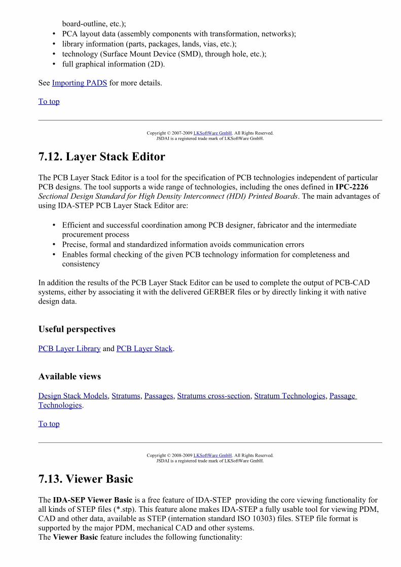
board-outline, etc.); • PCA layout data (assembly components with transformation, networks); • library information (parts, packages, lands, vias, etc.); • technology (Surface Mount Device (SMD), through hole, etc.); • full graphical information (2D).
See Importing PADS for more details.
To top
Copyright © 2007-2009 LKSoftWare GmbH. All Rights Reserved.JSDAI is a registered trade mark of LKSoftWare GmbH.
7.12. Layer Stack EditorThe PCB Layer Stack Editor is a tool for the specification of PCB technologies independent of particular PCB designs. The tool supports a wide range of technologies, including the ones defined in IPC-2226 Sectional Design Standard for High Density Interconnect (HDI) Printed Boards. The main advantages of using IDA-STEP PCB Layer Stack Editor are:
• Efficient and successful coordination among PCB designer, fabricator and the intermediate procurement process
• Precise, formal and standardized information avoids communication errors • Enables formal checking of the given PCB technology information for completeness and
consistency
In addition the results of the PCB Layer Stack Editor can be used to complete the output of PCB-CAD systems, either by associating it with the delivered GERBER files or by directly linking it with native design data.
Useful perspectives
PCB Layer Library and PCB Layer Stack.
Available views
Design Stack Models, Stratums, Passages, Stratums cross-section, Stratum Technologies, Passage Technologies.
To top
Copyright © 2008-2009 LKSoftWare GmbH. All Rights Reserved.JSDAI is a registered trade mark of LKSoftWare GmbH.
7.13. Viewer BasicThe IDA-SEP Viewer Basic is a free feature of IDA-STEP providing the core viewing functionality for all kinds of STEP files (*.stp). This feature alone makes IDA-STEP a fully usable tool for viewing PDM, CAD and other data, available as STEP (internation standard ISO 10303) files. STEP file format is supported by the major PDM, mechanical CAD and other systems. The Viewer Basic feature includes the following functionality:

• opening STEP, XIM files ; • viewing STEP file content. Available views:
• Datasets , • Header ,• Log View , • 2D View , • 3D View , • Display Settings , • Part Details , • Design Stack Models , • Documents , • Parts , • Passage Technologies , • Passages ,• Persons and Organizations , • Stratum Technologies , • Stratums , • Stratums Cross-section ,• Tasks , • Zonal Breakdown .
• manipulating with perspectives: opening, creating, switching, customizing.

Figure 1. IDA-STEP Viewer Basic feature views
To top
Copyright © 2007-2009 LKSoftWare GmbH. All Rights Reserved.JSDAI is a registered trade mark of LKSoftWare GmbH.
7.14. Viewer Pro 3DThe Viewer Pro 3D provides extended viewing capabilities in a 3D area:
• dynamic columns for customization of data displaying tables, • Geometry Details view extension (hide/show components, change colour, change transparency,
editing styling model), • GD&T for managing GD&T elements: tolerances, dimensions, annotations and etc.;
Note. It is not possible to save the created data.• measurement support in the 3D view; • printing the contents of the active view; • exporting of 3D model data to VRML file, STL file.
Figure 1. IDA-STEP Viewer Pro 3D functionality presentation - transparency, changed colour
To top
Copyright © 2007-2011 LKSoftWare GmbH. All Rights Reserved.JSDAI is a registered trade mark of LKSoftWare GmbH.
8. Pre-defined PerspectivesIDA-STEP predefined perspectives are:

• GDT , • Parts 3D ,• PCB/PCA , • PCB Layer Library , • PCB Layer Stack , • Tasks .
See also:
• Perspectives Preferences • Perspectives
To top
Copyright © 2009-2011 LKSoftWare GmbH. All Rights Reserved.JSDAI is a registered trade mark of LKSoftWare GmbH.
8.1. GDT
The GDT perspective (see Figure 1) is optimised for reviewing and creating, resp. modifying GD&T data (Geometrically Dimensioning and Tolerancing). For this purpose it is important to have the full height for the GD&T view available. The perspective consist of the following views:
• GD&T, • Geometry Details, • Parts, • Header, • 3D View, • Log.
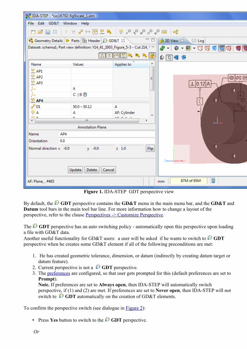
Figure 1. IDA-STEP GDT perspective view
By default, the GDT perspective contains the GD&T menu in the main menu bar, and the GD&T and Datum tool bars in the main tool bar line. For more information how to change a layout of the perspective, refer to the clause Perspectives -> Customize Perspective.
The GDT perspective has an auto switching policy - automatically open this perspective upon loading a file with GD&T data. Another useful functionality for GD&T users: a user will be asked if he wants to switch to GDT perspective when he creates some GD&T element if all of the following preconditions are met:
1. He has created geometric tolerance, dimension, or datum (indirectly by creating datum target or datum feature).
2. Current perspective is not a GDT perspective. 3. The preferences are configured, so that user gets prompted for this (default preferences are set to
Prompt). Note. If preferences are set to Always open, then IDA-STEP will automatically switch perspective, if (1) and (2) are met. If preferences are set to Never open, then IDA-STEP will not switch to GDT automatically on the creation of GD&T elements.
To confirm the perspective switch (see dialogue in Figure 2):
• Press Yes button to switch to the GDT perspective.
Or

• Press No or Cancel button to stay in the currently opened perspective.Note. You can make an application to remember your selection by selecting the Remember my decision option.
Figure 2. Confirm perspective switch dialogue window
The GD&T view in the GDT perspective displays the GD&T data of the part, selected in Parts view. The GD&T elements, selected in the GD&T view are highlighted in the 3D View (in case the
button is pressed) and in the Geometry Details view.
See also: Preferences -> General -> Perspectives Perspectives -> Customize Perspective
To top
Copyright © 2010-2011 LKSoftWare GmbH. All Rights Reserved.JSDAI is a registered trade mark of LKSoftWare GmbH.
8.2. Parts 3D
The Parts 3D perspective is designed to make a work with 3D objects more convenient. The perspective consists of the following views (see Figure 1):
• Parts,• Part Details, • 3D View, • Log, • Header.

Figure 1. 3D View perspective view
The Parts view presents the list of part versions, available in the current dataset. The Part Details view presents a hierarchy of part version definitions which are geometrically presented in the 3D View. The views in this perspective are connected in the following way:
• Selecting a part version in the Parts view, the Part Details view (also the Geometry Details view, which is available in the IDA-STEP Viewer Pro and editors) presents the hierarchy of part version definitions and the selected part version (an assembly or a single part) is geometrically presented in the 3D View (see Figure 2).

Figure 2. Part assembly version ('L_BRACKET_ASSEMBLY') in the Parts view, the hierarchy of part version definitions in the Part Details view and
3D geometrical representation in the 3D View
• Selecting an applicable component node in the Part Details view, highlights the particular component in the 3D View (see Figure 3). Also an applicable component can be selected in the
3D View. After the selection, the particular part version definition is highlighted in the Part Details view.
Figure 3. Selected component (bracket) is highlighted in 3D View
Note. The functionality, described below, is available only in IDA-STEP Viewer Pro.
• Selecting/Unselecting the Show/Hide check box next to an applicable component in the

Geometry Details view, shows/hides the particular component in the 3D View (see Figure 4).Note. The Geometry Details view can be opened by selecting Window -> Show view -> Other -> Geometry -> Geometry Details.
Figure 4. Selected component is hidden in 3D View together with all related components (unselected check boxes in Geometry Details view)
• Changing representation properties (transparency, surface or curve color) in the Geometry Details view (see Figure 5), the changes are reflected in the 3D View.
Figure 5. Changed transparency level value in Transparency column (Geometry Details view) and transparent object in 3D View
• Clicking on an applicable component in the 3D View (being in smart or picking mode), highlights the particular component node in the Geometry Details view (see Figure 6).

Figure 6. Picked component in 3D View is highlighted in Geometry Details view hierarchy
To top
Copyright © 2007-2009 LKSoftWare GmbH. All Rights Reserved.JSDAI is a registered trade mark of LKSoftWare GmbH.
8.3. PCB Layer Library
The PCB Layer Library perspective is optimized for managing stratum and passage technologies. The perspective consist of the following views (see Figure 1):
• Datasets - presents available datasets for the current repository, • Log,• Stratum Technologies - presents available stratum technologies with the defined properties, • Passage Technologies - presents available passage technologies with the defined properties.

Figure 1. PCB Layer Library perspective view
The views in this perspective are connected in the following way:
• Selecting an applicable dataset of type stratum technology in the Datasets view activates the Stratum technologies view (see Figure 1).
• Selecting an applicable dataset of type passage technology in the Datasets view activates the Passage technologies view (see Figure 2).

Figure 2. Selected dataset of type passage technology and activated Passage Technologies view
To top
Copyright © 2008 LKSoftWare GmbH. All Rights Reserved.JSDAI is a registered trade mark of LKSoftWare GmbH.
8.4. PCB Layer Stack
The PCB Layer Stack perspective is optimized for managing layers and other stratums, passages, design stack models and other PCB data. The perspective consist of the following views:
• Datasets - list of available datasets for the current repository, • Design Stack Models - presents a list of design stack models for the selected dataset, • Log, • Stratums - presents a tree table with a hierarchy of layers/stratums, referenced by a particular
design stack model, • Passages - presents a tree table with a hierarchy of passages, referenced by a particular design
stack model, • Stratums Cross-section - presents the visual 2D presentation of objects, defined in
Stratums and Passages view.

Figure 1. PCB Layer Stack perspective view
The views in this perspective are connected in the following way:
• Selecting a dataset of type design stack model in the Datasets view activates the Design Stack Models view. Other views are filled with available data for the first design stack model element (see Figure 2).

Figure 2. Activated Design Stack Model view and other views are shown with data
• Selecting a particular element in the Design Stack Model view shows the referred data in the Stratums, Passages and Stratums Cross-section views.
• Selecting an element in the Stratums view shows the selected element highlighted in the Stratums Cross-section view (see Figure 3).
Figure 3. Selected layer/stratum is highlighted in Stratums Cross-section view
• Selecting an element in the Passages view shows the selected element highlighted in the

Stratums Cross-section view (see Figure 4).
Figure 4. Selected passage is highlighted in Stratums Cross-section view
To top
Copyright © 2008 LKSoftWare GmbH. All Rights Reserved.JSDAI is a registered trade mark of LKSoftWare GmbH.
8.5. PCB/PCA
The PCB/PCA perspective is optimized for viewing PCB/PCA data, it consists of the following views (see Figure 1):
• Parts, • Header, • Part Details,• Display settings,• 2D View, • Log.

Figure 1. PCB/PCA perspective view
The Parts view contains the list of part versions, available in the opened repository. The Part Details view displays the assembly structure of PCA and its information. The content of Part Details view depends on selection in the Parts view. The 2D View provides convenient tools to examine the PCB layout and retrieve information on selected parts. The views in this perspective are connected in the following way:
• Selecting a PCA component in the Part Details view, highlights a particular component in 2D View (see Figure 2).

Figure 2. Selected part is highlighted in 2D View (red color)
• Changing settings in the Display settings view, the 2D View presents, how changes are applied to the design components (see Figure 3).
Figure 3. Changed color in Display settings view is applied to component in 2D View
To top
Copyright © 2007-2009 LKSoftWare GmbH. All Rights Reserved.JSDAI is a registered trade mark of LKSoftWare GmbH.

8.6. Tasks
The Tasks perspective is optimized for maintaining existing PDM data in the STEP files or to create a training system by indicating tasks and the corresponding information. The perspective consist of the following views (see Figure 1):
• Datasets, • Log, • Tasks, • Zonal Breakdowns, • Part Details, • Persons and Organizations, • Parts, • Documents.
Figure 1. Tasks perspective view
The views in this perspective are connected in the following way:
• Double clicking on a dataset in the Datasets view activates a particular view, the selected dataset is assigned to, on the screen.
To top

Copyright © 2009 LKSoftWare GmbH. All Rights Reserved.JSDAI is a registered trade mark of LKSoftWare GmbH.
9.1.1. Opening 2D Data View
Follow the routine to open 2D data view in the 2D View page:
• Open the Part Details view and 2D View in the workbench by using main menu Window -> Show View ->... .
• Open a particular STEP file, containing 2D data.
Or
• Select the PCA/PCB perspective by selecting in the main menu Window -> Open Perspective -> Other -> PCA/PCB.
• Click on the assembly node in the Part Details view to display it in the 2D View page. If the child element of the root assembly is selected in the Part Details view, it is highlighted in the 2D View.
To top
Copyright © 2007-2009 LKSoftWare GmbH. All Rights Reserved.JSDAI is a registered trade mark of LKSoftWare GmbH.
9.1.2. 2D View
The 2D View provides a two-dimensional geometry representation. Currently it includes zooming and scrolling, coloring and highlighting components.
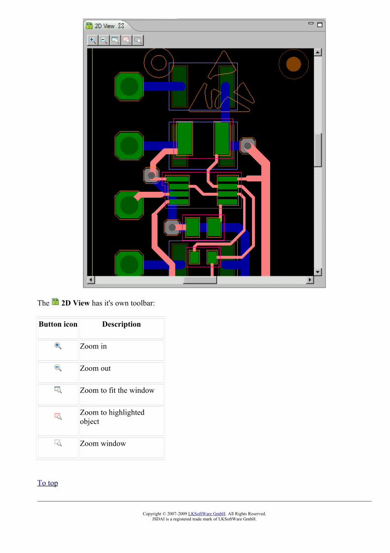
The 2D View has it's own toolbar:
Button icon Description
Zoom in
Zoom out
Zoom to fit the window
Zoom to highlighted object
Zoom window
To top
Copyright © 2007-2009 LKSoftWare GmbH. All Rights Reserved.JSDAI is a registered trade mark of LKSoftWare GmbH.

9.1.3. Zoom In
To increase a graphic view in the 2D View, click button. The graphic view is increased according to your clicking on the button.
Figure 1. Initial view
Figure 2. Zoomed in viewTo top
Copyright © 2007-2009 LKSoftWare GmbH. All Rights Reserved.JSDAI is a registered trade mark of LKSoftWare GmbH.
9.1.4. Zoom Out
To reduce a graphic view in the 2D View, click button. The graphic view is reduced according to your clicking on the button.

Figure 1. Initial view
Figure 2. Zoomed out viewTo top
Copyright © 2007-2009 LKSoftWare GmbH. All Rights Reserved.JSDAI is a registered trade mark of LKSoftWare GmbH.
9.1.5. Zoom to Fit
To apply a graphic view to the 2D View window, click button.

Figure 1. Initial view
Figure 2. Fit to window viewTo top
Copyright © 2007-2009 LKSoftWare GmbH. All Rights Reserved.JSDAI is a registered trade mark of LKSoftWare GmbH.
9.1.6. Zoom to Highlighted
To zoom and center the highlighted graphic object in the 2D View (see Figure 1), click button. The highlighted object is enlarged and centered in the 2D View (see Figure 2).
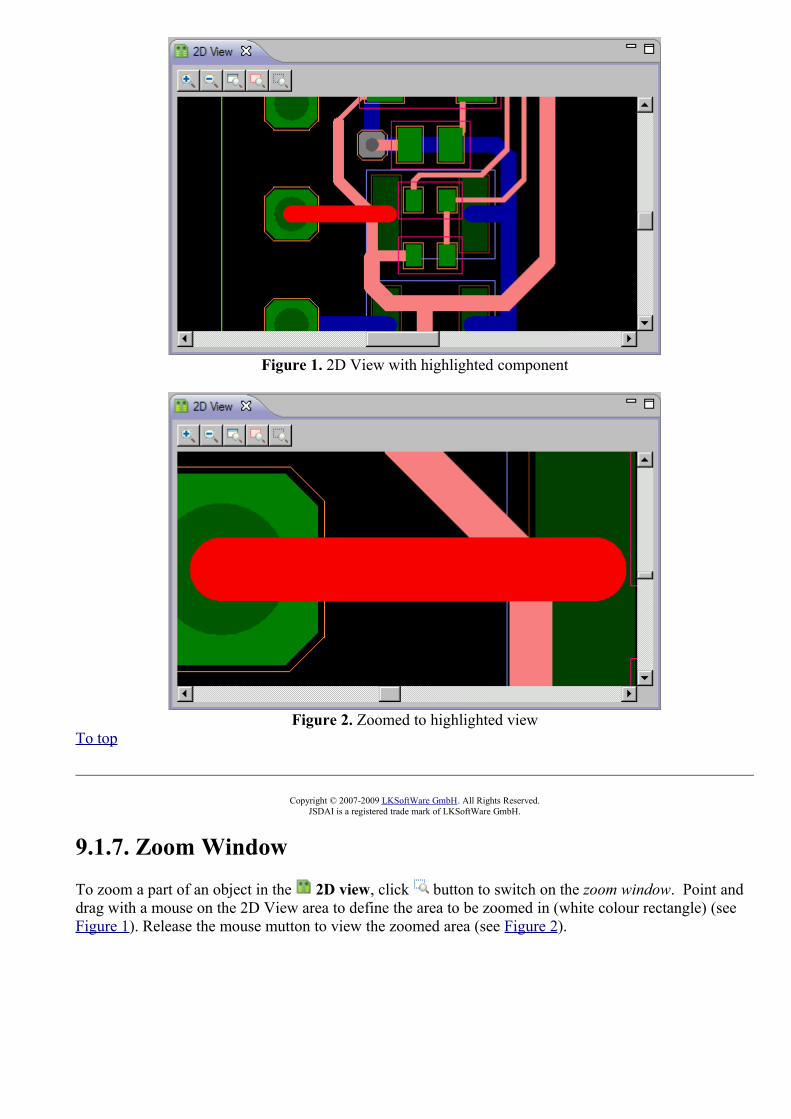
Figure 1. 2D View with highlighted component
Figure 2. Zoomed to highlighted viewTo top
Copyright © 2007-2009 LKSoftWare GmbH. All Rights Reserved.JSDAI is a registered trade mark of LKSoftWare GmbH.
9.1.7. Zoom Window
To zoom a part of an object in the 2D view, click button to switch on the zoom window. Point and drag with a mouse on the 2D View area to define the area to be zoomed in (white colour rectangle) (see Figure 1). Release the mouse mutton to view the zoomed area (see Figure 2).

Figure 1. Selected area (left side) is zoomed in (right side)
Figure 2. Zoomed area viewTo top
Copyright © 2007-2009 LKSoftWare GmbH. All Rights Reserved.JSDAI is a registered trade mark of LKSoftWare GmbH.
9.1.8. Highlight Object
To highlight an object in the 2D View:
• Click on a graphic object in the 2D View area. Note: there can be several objects in the pointed area, therefore a context sensitive menu appears to select a particular object you want to highlight.
• Select an object from the context sensitive menu. The selected object is highlighted (by default, red colour) (see Figure 1). You can change highlighting colour in the Display settings view.

Figure 1. The selected object is highlighted in 2D View directly
To top
Copyright © 2007-2009 LKSoftWare GmbH. All Rights Reserved.JSDAI is a registered trade mark of LKSoftWare GmbH.
9.1.9. Display Settings
The Display settings view provides a possibility to customize colours for the graphical representation in the 2D View (see Figure 1).

Figure 1. Display settings view and 2D View
• Basic settings layout: change the colour of the Background, Selection (zoom window rectangle) and Highlighting.
• Pca (Printed Circuit Board) layout: change the colour, filling visibility modes of the Top and Bottom side of the PCA.
• Pcb (Printed Circuit Board) layout: change the colour, filling visibility modes of the Inter stratum, PCB components in a particular stratum (layer).The PCB components and layers are presented in the table:
• Component name (column header): P (pads), R (Traces), V (vias), T (text), C (copper), F (fiducial).
• Stratum name (row header): T S/M .006, T S/PASTE, 1ST SIGNAL, dielectric 11, bot, B S/M .006, B S/PASTE.
Changing colour
To change colour for a particular component:
• Click the first mouse button on a button with a colour square next to an applicable component. The Color dialog window appears (see Figure 2).
Figure 2. Color dialog window
• Click on an applicable colour in the Basic color or Custom colors layout.Or
• Define your custom colour by clicking on the Define Custom Colors button. The additional part of the dialog window appears (see Figure 3).
Figure 3. Color dialog window to add custom colour
• Select a colour and click Add to Custom Colors button. • A square with a chosen colour appears in the Custom colours layout (on the left). • Click OK button.
• The colour of the selected component is changed.
The Pcb layout contains a table with a possibility to make the same colour for the component in all stratums or for all components in one stratum:

Figure 4. Table view
• Click the first mouse button on the button with the white square icon below the component (P (pads), R (Traces), V (vias), T (text), C (copper), F (fiducial)) to change a colour for a particular component in all stratums.
• Click the first mouse button on the button with the white square icon next to the stratum name (T S/M .006, T S/PASTE, 1ST SIGNAL, dielectric 11, bot, B S/M .006, B S/PASTE) to change a colour for all components in a particular stratum.
Changing filling mode
A button icon next to a particular component indicates, whether the components is filled or outlined:
• - filled; • - outlined.
To change a filling mode of a particular component click the second mouse button on a button with a colour square next to an applicable component.You can change a filling mode for the component in all stratums or for all components in one stratum:
• Click the second mouse button on the button with the white square icon below the component (P (pads), R (Traces), V (vias), T (text), C (copper), F (fiducial)) to change a filling for a particular component in all stratums.
• Click the second mouse button on the button with the white square icon next to the stratum name (T S/M .006, T S/PASTE, 1ST SIGNAL, dielectric 11, bot, B S/M .006, B S/PASTE) to change a filling mode for all components in a particular stratum.
Changing visibility
The icon button indicates, that the current component is not visible in the 2D View.To change visibility of a particular component click the third mouse button on a button next to an applicable component.
To top
Copyright © 2007-2009 LKSoftWare GmbH. All Rights Reserved.JSDAI is a registered trade mark of LKSoftWare GmbH.

9.2.1. Displaying Geometry in 3D View
The 3D View is driven by the Parts view. As long as no part is selected in the Parts view, nothing is displayed in the 3D View. Also nothing is displayed if no 3D geometry is defined for the selected part. IDA-STEP is configured in such a way, that a part from the Parts view is automatically selected and displayed in the 3D View.
STEP data is defined by different kinds of curves (line, circle, spline, etc.) and surfaces (plane, sphere, toroidal, etc.). To be able to display this data by computer, the curves have to be interpolated by short line segments and the surfaces have to be emulated by small triangles. This process,called triangulation or tessellation, is time consuming. During this process a dialog with a process bar shows up (see Figure 1). To avoid repeated tessellations the result is stored together with it's originating STEP data in the XIM file. That is a reason why the Viewer Pro feature, when opening a STEP file is asking on whether or not to create a corresponding XIM file. The Viewer Basic alone will do the tessellation always anew.
Figure 1. Preparing shape for display window with a process bar
Follow the routine to open 3D geometry in the 3D View page:
• Open the Parts view and 3D View in the workbench by using main menu Window -> Show View ->... .
• Open a particular STEP file, containing 3D data.
Or
• Select the Parts 3D perspective by selecting in the main menu Window -> Open Perspective -> Other -> Parts 3D.
• Click on an applicable part version element in the Parts view to display it in the 3D View page (see Figure 2).
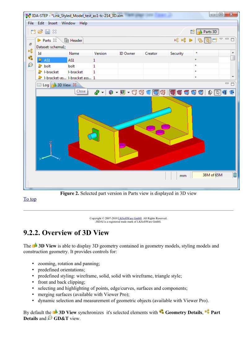
Figure 2. Selected part version in Parts view is displayed in 3D viewTo top
Copyright © 2007-2010 LKSoftWare GmbH. All Rights Reserved.JSDAI is a registered trade mark of LKSoftWare GmbH.
9.2.2. Overview of 3D View
The 3D View is able to display 3D geometry contained in geometry models, styling models and construction geometry. It provides controls for:
• zooming, rotation and panning; • predefined orientations; • predefined styling: wireframe, solid, solid with wireframe, triangle style;• front and back clipping; • selecting and highlighting of points, edge/curves, surfaces and components; • merging surfaces (available with Viewer Pro);• dynamic selection and measurement of geometric objects (available with Viewer Pro).
By default the 3D View synchronizes it's selected elements with Geometry Details, Part Details and GD&T view.

Figure 1. 3D viewer with a 3D geometry
The 3D View has it's own tool bar and context sensitive menu.
Toolbar
Tool bar buttons are provided for changing appearance of 3D geometry, selection of modes, styling, moving, shifting, picking, clipping and etc.:
Button icon Description
Predefined Orientation (Front):
• Overview• Top • Front • Left • Right • Back • Bottom • SW Isometric• SE Isometric • NE Isometric • NW Isometric
Style/Annotation Model
• Unselect active style/annotation model - press the button; • Activate style/annotation model/saved view - select model/saved view
in the drop down list; • Ignore styling - select the Ignore styling item in the list;

• Save current 3D view - select the Save current 3D view item;• Change active and bring to front annotation plane - select an
annotation plane item in the drop down list to make it active and bring to front the underlying annotation plane so that it is aligned in the right reading position to the actual camera position.
Note. This function is available only with 3D Viewer Pro feature.
Styling Preference
Select default styling schema in the drop down list. See also Preferences - > 3D View -> Display Styles
Wireframe with Hidden Line Removal Style
Wireframe Style
Solid Style

Solid with Wireframe Style
Triangle Style
Component/Model Selection Mode
Face/Surface Selection Mode
Note. This function is available only with 3D Viewer Pro feature.

Edge/Curve Selection Mode
Note. This function is available only with 3D Viewer Pro feature.
Annotation Selection Mode
Note. This function is available only with GD&T Editor feature.
Vertex/Point Selection Mode
Note. This function is available only with 3D Viewer Pro feature.
Point on Edge or Face Selection Mode
Note. This function is available only with 3D Viewer Pro feature.
Dynamic Selection Mode
• highlighting - flying by with a mouse pointer• rotating - mouse drag, • zooming - mouse drag up/down with Ctrl key pressed or rolling

forward/backward with mouse wheel, • panning - mouse drag with Alt key or mouse wheel pressed.
Note. This function is available only with 3D Viewer Pro feature.
Normal Selection Mode
• select/highlight - mouse click, • rotating - mouse drag, • zooming - mouse drag up/down with Ctrl key pressed or rolling
forward/backward with mouse wheel,• panning - mouse drag with Alt key or mouse wheel pressed.
Clip front mode Mouse drag up/down
Clip back mode Mouse drag up/down
Context sensitive menu
The context sensitive menu groups functions, which are available in the 3D View (see Figure 2):
Figure 2. Context sensitive menu in 3D ViewFunctions, available with 3D Viewer Pro feature:
• Bring to front - to change orientation of the geometry object according the selected surface.• Select point - to set a point on the geometry object.• Optimize geometry - combine neighbouring faces (cylinders, cones, spheres) when their
underlying surface is the same or equivalent.
Functions, available with GD&T Editor feature:
• Datum Feature - to create an actual surface component to establish a datum. • Datum Target - to create a specified point, line or area on a part that is used in establishing a
datum. This menu item contains a sub menu, where available datum target types are listed: Point Datum Target, Line Datum Target, Circle Datum Target, Circular Curve

Datum Target and Rectangle Datum Target (see Figure 3).
Figure 3. Datum Target sub menu items
• Datum System - to create a group of one or more separate datums used as a combined reference for a toleranced feature.
• Geometric Tolerance - to create a geometrical tolerance for selected geometry component. • Dimension - to add measurement annotation to a geometry object. This menu contains a sub
menu, where available dimensions are listed (see Figure 4): • Angle - to create an angular dimension annotation.• Size - to create a radius, a diameter or a length dimension annotation.• Distance - to create a distance dimension annotation.
Figure 4. Dimension sub menu items
• Annotation Plane - to create a conceptual plane, which contains annotations.• Text Annotation - to create a 3D annotation with a free text, one or several line. • Shape Aspect - to create an element of the shape of a product. • Supplemental Geometry - to create supplemental geometry elements. This menu contains a sub
menu, where available supplemental geometry elements are listed: Apex, Symmetry Axis, Symmetry Plane, Symmetry Point, Common Line, Common Plane, Intersection, Offset, Perpendicular Line, Perpendicular Plane, Extension, Tangent Plane, Line and Plane (see Figure 5). Note. There are enabled only those menu items, which represent functions available for the current selection.
Figure 5. Supplemental Geometry sub menu items

• Align Offset - to align the offset of annotations on the same annotation plan.
To top
Copyright © 2007-2012 LKSoftWare GmbH. All Rights Reserved.JSDAI is a registered trade mark of LKSoftWare GmbH.
9.2.3. Predefined OrientationsThe predefined orientations provide an easy way to set the orientation for the displayed geometry to precise orientation, panning and zooming values. The predefined orthographic and isometric orientations are listed in the drop down list next to the Reset to Front button in the 3D View, they are:
• Overview: switch back from a zoomed-in state to an overview without changing the orientation. • Orthographic orientations: Top (see Figure 1), Front, Left, Right, Back, and Bottom. • Isometric orientations: SW (southwest) Isometric, SE (southeast) Isometric (see Figure 2), NE
(northeast) Isometric, and NW (northwest) Isometric. • Relative 90 degrees rotation around axes:
• RX +90 - 90 degrees clockwise rotation around X axis, • RX -90 - 90 degrees counter-clockwise rotation around X axis, • RY +90 - 90 degrees clockwise rotation around Y axis, • RY -90 - 90 degrees counter-clockwise rotation around Y axis, • RZ +90 - 90 degrees clockwise rotation around Z axis, • RZ -90 - 90 degrees counter-clockwise rotation around Z axis,
Figure 1. Top orientated object view

Figure 2. SE (southeast) isometric oriented object view
Click Reset to Front button to reset default settings of the current 3D object orientation, size and position in the 3D View, if rotation, zooming, panning or clipping was performed.
See also Preferences -> 3D View -> Front side orientation.
To top
Copyright © 2007-2009 LKSoftWare GmbH. All Rights Reserved.JSDAI is a registered trade mark of LKSoftWare GmbH.
9.2.4. Save Current 3D View
The rotated and magnified geometry model view, currently active in the current 3D View, can be saved and used for reviewing in the future.Follow the routine to save the current 3D view:
• Activate the 3D View. • Click on the arrow next to the Styled Model button. • Select Save current 3D view... item in the appeared drop down list (see Figure 1).
Figure 1. 3D View page with Styled model drop down list, selected Save current 3D view... menu item
• The Creation of the saved view dialogue window appears (see Figure 2):

Figure 2. Creation of the saved view dialogue window
• Enter the name of the saved view into the text field. The prompted name is Saved View 1. You can edit this text or enter a new one. If there already exist the saved view with the same name in the parent styled model, a view is overwritten with the last one.
• Click OK button. • The saved view is located under the currently active styling model (see Figure 3). Note. The
parent styled model is activated together with the saved view (both of them are highlighted in the context sensitive menu).
Figure 3. Created Saved View 1 in the drop down list
To activate a saved view, select an applicable item in the Styled Model drop down list. The selected saved view is displayed with the check mark or switched On icon in front of the saved view name. Note. The parent styled model is activated together with the selected saved view. If the rotation or zooming of the geometry model is changed in the 3D View, the check mark in front of the previously selected saved view in the Styled Model drop down list disappears or the switched On icon becomes the normal state icon.
How to rename and remove an applicable saved view, see Saved Views (if Geometry Details view is available).
To top
Copyright © 2010-2011 LKSoftWare GmbH. All Rights Reserved.JSDAI is a registered trade mark of LKSoftWare GmbH.

9.2.5. Appearance Style
Adjust the 3D geometry representation appearance in the 3D View. Use one of the button in the 3D View tool bar (see Figure 1).
Figure 1. Tool bar buttons to change appearance of the 3D geometry representation
In case all appearance mode buttons are Off, the 3D View area is empty, unless some Styling Model is previously selected, then the styled items are displayed.
Note. When starting IDA-STEP anew the default Solid With Wireframe Syle is applied.
Wireframe with Hidden Line Removal
• Click button on the tool bar to view a wireframed 3D object, where lines (or segments of lines) covered by surfaces are not drawn (see Figure 2).
Figure 2. Wire frame without hidden lines viewTo top
Wireframe
• Click button on the tool bar to view wire-framed 3D object view. The “Wireframe” is a graphic view, where 3D body is displayed as a “red” wire frame, consisting of curves only (see Figure 3).

Figure 3. Wireframe view of 3D objectTo top
Solid
• Click button to view a solid 3D object view. The “Solid” is a graphic view, where 3D body is displayed as a coloured solid (see Figure 4).
Figure 4. Solid view of 3D objectTo top
Solid with Wireframe
• Click button to view a solid 3D object view with wire frame lines. “Solid with Wireframe” is a combined graphic view, where 3D body is displayed as both solid and wire frame (see Figure 5).

Figure 5. Solid and wireframe view of 3D objectTo top
Triangle
• Click button to view a 3D object, where surfaces are displayed as wire frame triangles (see Figure 6).
Figure 6. 3D object where surfaces shown as trianglesTo top
Copyright © 2007-2009 LKSoftWare GmbH. All Rights Reserved.JSDAI is a registered trade mark of LKSoftWare GmbH.
9.2.6. Style/Annotation Model
By default a geometry model in the 3D View is displayed by using default styling schema, which is defined in the 3D View -> Display Styles preferences and currently selected in the Styling Preference list.
Style/Annotation Model
There can be several styling models created in STEP file data. There are two different kind of information
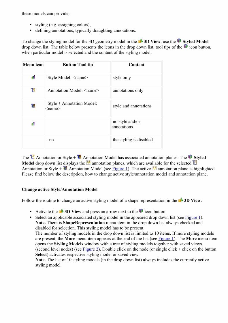
these models can provide:
• styling (e.g. assigning colors),• defining annotations, typically draughting annotations.
To change the styling model for the 3D geometry model in the 3D View, use the Styled Model drop down list. The table below presents the icons in the drop down list, tool tips of the icon button, when particular model is selected and the content of the styling model.
Menu icon Button Tool tip Content
Style Model: <name> style only
Annotation Model: <name> annotations only
Style + Annotation Model: <name> style and annotations
no style and/or annotations
-no- the styling is disabled
The Annotation or Style + Annotation Model has associated annotation planes. The Styled Model drop down list displays the annotation planes, which are available for the selected Annotation or Style + Annotation Model (see Figure 1). The active annotation plane is highlighted.Please find below the description, how to change active style/annotation model and annotation plane.
Change active Style/Annotation Model
Follow the routine to change an active styling model of a shape representation in the 3D View:
• Activate the 3D View and press an arrow next to the icon button. • Select an applicable associated styling model in the appeared drop down list (see Figure 1).
Note. There is ShapeRepresentation menu item in the drop down list always checked and disabled for selection. This styling model has to be present.The number of styling models in the drop down list is limited to 10 items. If more styling models are present, the More menu item appears at the end of the list (see Figure 1). The More menu item opens the Styling Models window with a tree of styling models together with saved views (second level nodes) (see Figure 2). Double click on the node (or single click + click on the button Select) activates respective styling model or saved view. Note. The list of 10 styling models (in the drop down list) always includes the currently active styling model.

Figure 1. 3D View, list of associated models (active style is highlighted (icon) in the list), Ignore styling item, Save current 3D view item and a list of available annotation planes ('Front View.1' and etc.) for the
currently active style and annotation model.
Figure 2. Styling models window, tree of styling models and saved views
The selected styling model is made active for the 3D geometry in the 3D View.
After some styling model is selected, the icon drop down list is extended with one more menu item, i.e. Ignore styling. After this menu item is selected, the style information is ignored and now the 3D View displays geometry model and annotations (if any) without style. The default styling schema is used,

which is currently active (selected in the Styling Preference list).
To disable the active styling model, press icon button.
Change active and bring to front Annotation Plane
The annotations (if any) of the current 3D view are listed at the end of the menu. Any press on an annotation plane make it always both Active and Bring it to front (bring to front the underlying annotation plane so that it is aligned in the right reading position to the actual camera position).
Follow the routine to change active annotation plane nd bring to front in the 3D View:
• Activate the 3D View and press an arrow next to the icon button. • Select an applicable annotation plane in the appeared drop down list (end of the list). Note. The
active Style/Annotation Model should have associated annotation planes. Note. Any press on an annotation plane make it always both active and bring it to front. Pressing the second time on already active annotation plane, just bring it to front.
In case a new annotation plane is created in the 3D View, it becomes the currently active annotation plane.
Styling Preferences
The default active styling schema for the geometry model is set in the preferences 3D View -> Display Styles page. The Styling Preference in the 3D View contains a drop down list with available styling schemas. A user can select an applicable styling schema and make it active directly in the 3D View, without calling preference page. The active schema is marked with a check mark in the drop down list.Note. After a styling schema is selected, it is made as an active schema in preferences 3D View -> Display Styles page.
To top
Copyright © 2007-2011 LKSoftWare GmbH. All Rights Reserved.JSDAI is a registered trade mark of LKSoftWare GmbH.
9.2.7. Selection ModesThe Selection Mode determines which scene elements can be selected and manipulated at a given time. There are some object selection modes available in IDA-STEP 3D View: normal, dynamic, component, face, edge and vertex selection mode. An applicable selection mode can be switched On by pressing a particular button in the 3D View tool bar (see Figure 1).
Figure 1. Buttons to switch selection mode
When starting IDA-STEP anew and displaying STEP file in 3D View the default selection modes are active:
• Component/Model Selection Mode for assemblies and • Face/Surface Selection Mode for a single piece part.

The user has a possibility to switch On several selection modes to be available at once. For example: Face/Surface + Edge/Curve + Annotation + Vertex/Point - user can select everything on the fly with a kind of snapping for vertexes, edges and faces.Note. To switch Off a selection mode - unpress the particular button.
Component/Model
The Component/Model selection mode lets you select a certain component of an object.
To top
Face/Surface
The Face/Surface selection mode lets you select the individual faces (also known as polygons) which comprise an object.
To top
Edge/Curve
The Edge/Curve selection mode lets you select individual edges/curves. Edge/curves are used to define boundaries between neighbouring surfaces or for annotation purposes.
To top
Annotation
The Annotation selection mode lets you select all types of annotations.
To top
Vertex/Point
The Vertex/Point selection mode lets you select the individual vertices (also known as points or control points) which define the faces and edges of a model.
To top
Point on Face or Edge
The Point on Face or Edge selection mode lets you select a point on a face or edge of a geometry:
• to select a point on a face, the Face /Surface selection mode should to be tuned On; • to select a point on an edge, the Edge/Curve selection mode should be turned On.
Note. The above functionality can be achieved if the Component/Model selection mode is turned On, but more convenient is to use the appropriate selection modes (face or edge).
If the Point on Face or Edge selection mode is On together with one of selection modes mentioned

above - both things (component, face, edge + point) are shown and highlighted.The selection of a point can be executed by:
• Left mouse single click, or• Right click and selecting Select point menu item in the appeared context sensitive menu.
After pointing with a mouse on a solid geometry object (face, annotation plane, filled terminator symbol, etc.), the Bring to front context sensitive menu item appears. By selecting this menu item, the geometry object will be oriented according the selected surface.
To top
Normal
The Normal selection mode lets you select an object component by clicking on it with a mouse button.
Cross-highlighting
When selecting some object in the 3D View, the associated data are highlighted in the Geometry Details and GD&T views. Lets' examine, how the Geometry Details and GD&T views are affected after the Annotation Selection Mode is switched On and some annotation is selected in the 3D View (see Figure 2):
1. Ensure the Normal and Annotation Selection Mode are switched On. 2. Pick with a mouse on an applicable annotation in the 3D View. The particular object is
highlighted together with the associated shape feature. 3. The node, which represents the selected object, is highlighted in the Geometry Details view. 4. The GD&T objects, which are related to the selected annotation, are highlighted in the GD&T
view.

Figure 2. Selected annotation in 3D View with cross-highlighted data in 3D View (associated feature), Geometry Details and GD&T view
To top
Dynamic
The Dynamic selection mode lets you to select an object without clicking on it. A particular object is selected while dragging with a released mouse button. Note. In case an annotation is selected in the 3D View, the associated shape feature is highlighted at the same time.
To top
Copyright © 2009-2011 LKSoftWare GmbH. All Rights Reserved.JSDAI is a registered trade mark of LKSoftWare GmbH.
9.2.8. View Control
You can select/highlight, pan, zoom in/out and rotate a 3D object in the 3D View. To control a 3D object you have to switch On the Normal Selection or Dynamic Selection modes by pressing a particular button in the 3D View tool bar.

Select/Highlight
To select/highlight an object in the 3D View, click on an applicable object. The object is highlighted (see Figure 1). Which scene elements can be selected and manipulated at a given time determines the Selection Mode.
Figure 1. Selected/highlighted object (red coloured)
There is another way to highlight an applicable object in the 3D View:
• Select an applicable object in the Part Details view or in the Geometry Details view (if available).
• The selected component is highlighted in the 3D View (see Figure 2).
Figure 2. Selected object (in Part Details view) is highlighted in 3D view and vice versa
Note. To highlight annotation planes, annotation occurrences, construction geometry planes in the 3D View, use Edge/Curve Selection Mode.
To top
Rotate
To move a 3D object into a circular motion around a particular axis:
• Click and hold with any mouse button on the 3D View area.

• Drag to any direction to rotate an object. The object rotates according to the mouse movement.
To top
Zoom In/Out
To enlarge or reduce a 3D object in the 3D View:
• Move the mouse cursor over the feature you are going to zoom in/out.• Rotate the mouse wheel: backward - to enlarge (zoom in) the object; forward - to reduce (zoom
out) the object.
Or
• Press CTRL key and click on the the 3D View area. • Hold and drag upwards to reduce (zoom out) the object.
Or• Hold and drag downwards to enlarge (zoom in) the object.
The object in the 3D View reduces or increases according to the mouse wheel/mouse movement. The center of the zooming area is the area, over which the mouse cursor was set.Note. You can change zooming direction in Preferences -> 3D View.
To top
Pan
To pan an object in the 3D View:
• Press the mouse wheel or ALT key + click on the 3D object. • Hold and drag the 3D object to any direction. The object moves according to the mouse
movement.
To top
Copyright © 2009-2011 LKSoftWare GmbH. All Rights Reserved.JSDAI is a registered trade mark of LKSoftWare GmbH.
9.2.9. Front and Back Clipping PlaneDiving into / Clipping allows studying some details without being disturbed by front and back objects.
• Click button to turn On Clip front Mode. The north - south cursor type appears (see Figure 1).

Figure 1. Clip front mode turned On, north-south cursor type
• Click and drag the mouse upwards to dive into a front clipping plane of the 3D object (see Figure 2).
• Click and drag the mouse downwards to restore an initial shape of a 3D object.
Figure 2. Clipped front plane
• Click button to turn On Clip back mode. he north - south cursor type appears. • Click and drag a mouse downwards to dive into a back clipping plane of the 3D object (see Figure
3). • Click and drag a mouse upwards to restore an initial shape of a 3D object.

Figure 3. Clipped front and back planesTo top
Copyright © 2007-2009 LKSoftWare GmbH. All Rights Reserved.JSDAI is a registered trade mark of LKSoftWare GmbH.
9.2.10. Inspecting Model
IDA-STEP presents a dynamic inspection of a model in the 3D View. When a user is pointing with a mouse on a 3D object in the 3D View, particular information is displayed in the IDA-STEP status bar. This information can be copied to the clipboard and then pasted to any text editor.Note. Dynamic selection mode have to be switched On.
The following information can be displayed in the status bar:
• Component reference designator, when a particular component is selected (see Figure 1);
Figure 1. Status bar information, when component is dynamically selected (i.e. 'PLATE_1' - highlighted in red colour)
• Type of underlying surface (plane, cylinder with radius and etc.), an identifier of entity instance (#number), measurement units (see Figure 2);

Figure 2. Status bar information: type of underlying surface ('Cylinder'), entity instance identifier ('#2043'), radius ('Radius=0,50') and measurement units (cm)
• Type of underlying curve with an absolute coordinates of the Start and End points, measurement units (see Figure 3);
Figure 3. Status bar information: type of underlying curve ('Line'), entity instance identifier ('#1554'), Start point absolute coordinates ('Start=(-2,14; -0,48; 1,00)').
Note. The End point coordinates and measurement units are not visible in the Figure 3, because the window is minimized
• Point coordinates - absolute and relative, distance on the 3D object (see Figure 4). Refer to the Clause Measuring for more details.

Figure 4. Status bar information: Absolute coordinates of blue point ('Abs. 15,80; 14,38; 2,00') and measurement units (cm)
Note. How to select particular object (component, surface, curve or point), please refer Clause Selection Modes. The measurement units are displayed in the status bar according settings, selected in the Preferences page Quantities and Units panel (it can be accessed by selecting Window -> Preferences -> Numbers -> Quantities and Units).
Information in the status bar may be copied (CTRL + C) and pasted in a preferable editor. Follow the routine to copy a dynamic information in the 3D View:
• Press Dynamic selection button in the 3D View tool bar to switch the dynamic selection mode On.
• Press Face/Surface Selection Mode button to set the surface selection mode On (another selection mode can be selected).
• Fly with a mouse pointer by the surface you want to inspect. The particular information is displayed in the status bar (see Figure 2).
• Press CTRL + C keys (Don't move the mouse!). The information, that is displayed in the status bar is copied into the clipboard.
• Now open preferable editor and paste the information from the clipboard.
To top
Copyright © 2009 LKSoftWare GmbH. All Rights Reserved.JSDAI is a registered trade mark of LKSoftWare GmbH.
9.2.11. MeasuringWith a Viewer Pro component of IDA-STEP it is possible to measure distances between points, edges/curves and surfaces in the 3D View. Measurement is done in a Dynamic Selection Mode. First a single object (point, edge/curve or surface) is selected. In the case of a point, it's absolute coordinates are displayed in the statusbar. Then with the dynamic selecting another object is highlighted by moving the mouse over the object and relative coordinates (Rel.) of this object are displayed in the statusbar. The distance between the selected object and the highlighted one under the mouse is visualized by a white air-line. The measured distance together with units is displayed in the statusbar (see Figure 1).

Figure 1. Measuring between two arbitrary points
There is a quite big number of possible combinations (i.e. 36) of what can be measured between. The object type should be selected by switching On a particular selection mode in the 3D View tool bar. The components, which can be measured together with the selection mode combinations:
1. Face - Face/Surface Selection Mode, 2. Edge - Edge/Curve Selection Mode,3. Point - Vertex/Point or Point on Edge or Surface Selection Mode, 4. Point on Component - Component/Model and Point on Edge or Surface Selection Mode,5. Point on Face - Face/Surface and Point on Edge or Surface Selection Mode,6. Point on Edge - Edge/Curve and Point on Edge or Surface Selection Mode.
Follow the routine to measure a distance between two points/edges/faces:
• Ensure the Dynamic Selection Mode is activated.• First of all, you have to decide what object should be a start point and switch a particular selection
mode On in the 3D View tool bar. For example, the start point is a point on the face. So press on the Face/Surface Selection Mode and Point on Edge or Surface buttons in the tool bar.
• Now set a start point on the geometry object in the 3D View by pointing with a mouse on an applicable face. In some cases (for Point on Edge or Surface Selection Mode) you can select a point by mouse right click and selecting Select point menu item in the appeared context sensitive menu. The absolute coordinates of this selected point are displayed in the status bar (string 'Abs' in front of the coordinates). Only when dynamically setting the start point a user will dynamically see absolute coordinates. Otherwise only relative coordinates are displayed in the status bar. To switch back to the dynamic first point selection, press ESC key.Note. When measuring distance between objects (faces, edges) the start point position is not set by the user, it is assumed to be the nearest point of the face or edge to the end object.
• Now it is a time to set an end point. If the end point or object is the same type as a start point, fly by with a mouse over the geometry object and the end point flashes up for all near points, which match the active selection mode. The shortest distance line between the start and end points is displayed and the length message appears in the status bar every time a new end point is highlighted. If the end point type differs from the start point or object, switch an applicable

selection mode On and then fly by with a mouse over the geometry object to measure a distance.For example the end point is an edge, so press on Edge/Curve (available for Solid with Wireframe Style) and fly by with a mouse over the geometry object. The point flashes up for all near points on the wire frames.Note. Right after the mouse pointer is moved, the relative mode is switched On. That means the coordinates in the status bar are displayed with the string 'Rel.'. The coordinates are displayed as delta-x, delta-y, delta-z from the start point to the end point. To switch back to the dynamic start point selection, press ESC key.
Please find some examples below.
Measure distance between two Faces
Let's measure a distance between two faces (see Figure 2):
• Turn On the Dynamic Selection Mode button. • Turn On the Face/Surface Selection Mode button. • Select an applicable face on the geometry model in the 3D View. • Fly by with a mouse over an applicable face/surface. The shortest distance between highlighted
faces is displayed in the statusbar.
Figure 2. Measurement between two faces
Measure distance between Face to Edge
Let's measure the shortest distance between a face and an edge:
• Turn On the Dynamic Selection Mode button. • Turn On the Face/Surface Selection Mode button. • Select an applicable face on the geometry model in the 3D View.• Turn On the Edge/Curve Selection Mode button. • Fly by with a mouse over an applicable edge/curve. The shortest distance is displayed in the
statusbar.

Measure distance between two Points
Let's examine, how to measure distances between two vertex points on components on objects within the 3D View:
• Turn On Dynamic Selection Mode. • Press Vertex/Point Selection Mode button - to select a vertex.• Fly by with a mouse pointer over the 3D object. The point flashes up for all near points. The
absolute coordinates ('Abs.') of these points are displayed in the status bar (see Figure 3). • Click on an object in the 3D View to set an anchor point - the start point of the measuring.
Note. Only when dynamically setting the first point a user will dynamically see absolute coordinates. Otherwise only relative coordinates are displayed in the status bar. To switch back to the dynamic start point selection, press ESC key.
Figure 3. Start point on geometry model, absolute coordinates of the start point in status bar
• Select an end point of the measuring line by flying by with a mouse on a 3D object. The point flashes up for all near vertex points. Right after the mouse pointer is moved, the relative mode is switched On and relative coordinates are displayed in the statusbar. The "air-length" between the start and end points is displayed on the right of the coordinates (see Figure 4).

Figure 4. End point and measuring data in statusbar
The measuring results are presented in the statusbar (see Figure 4):
1. Point coordinates (x, y, z): 1. Abs. - absolute anchor point coordinates; 2. Rel. - relative end point coordinates: delta-x, delta-y, delta-z from the anchor point
(white point) to the end point (blue point);2. Distance between the start and end points; 3. Measure units.
Note. The above measurement numbers and units are displayed according settings, selected in the Preferences page Quantities and Units panel (it can be accessed by selecting Window -> Preferences -> Numbers -> Quantities and Units). The colours of points (start/end point) can be changed in Window -> Preferences -> 3D View -> Display Styles -> Element colors (Highlighted color - for Vertex/Point).
Changing Measure Units
Let's examine, how to switch to another measure units, e.g. "inch" instead of "cm" (you can find measure units in the status bar of IDA-STEP). First of all open preferences page by selecting in the main menu bar Window -> Preferences -> Numbers -> Quantities and Units.
1. Select the length quantity in the table of the Quantities and Units page. 2. Select inch value from the list of available units for the selected quantity, which is located on the
right side of the length settings layout. 3. Press Set As Default button to set the selected unit as default unit. 4. Press OK button to confirm changes.

Figure 5. Quantities and Units page with steps to change measure units form current units (cm) to "inch"
The currently set units are displayed in the status bar of IDA-STEP. All measurements are recalculated (see Figure 6).
Figure 6. Status bar with changed units and recalculated coordinates
For more details see Preferences -> Numbers -> Quantities and Units.
To top
Copyright © 2007-2009 LKSoftWare GmbH. All Rights Reserved.JSDAI is a registered trade mark of LKSoftWare GmbH.
9.2.12. Optimize GeometryOptimize geometry is a tool to combine neighbouring faces (cylinders, cones, spheres) when their underlying surface is the same or equivalent. The faces (i.e. cylinders, cones or spheres) must have the same radius (maybe with some tolerance) and must have the same orientation in space.Optimizing algorithm also converts selected bspline surface to elementary surface (plane, cylinder, etc.) and converts bspline curves to elementary curves (lines, circles, etc.) if possible.The Optimize geometry command works either on the whole 3D model or only on selected faces, curves (multiple selection).

Optimize geometry of a whole 3D model
The Normal + Component/Model Selection Mode should be switched on in the 3D View.Follow the routine to combine all faces that belong together and convert bsplane faces/curves into elementary surfaces/curves:
• Select (highlight) a component in the 3D View. • Right click and select Optimize geometry menu item in the context sensitive menu (see Figure 1). • The Optimize geometry message window appears on the screen, containing information about
number of modified faces and curves (see Figure 2). Click OK button to close the message window.
Figure 1. Whole component highlighted in 3 D View and Optimize geometry menu item selected
Figure 2. Optimize geometry message window with list of modified elements
In case the geometry was previously optimized or there are no faces/curves to optimize, the particular message 'Nothing is modified from the list of curves, faces and surfaces' appears in the Optimize geometry message window (see Figure 3).
Figure 3. Optimize geometry message window informing there were nothing modified from the list of curves, faces and surfaces

Merge selected faces
First of all the Normal + Face/Surface Selection Mode should be switched on in the 3D View. Follow the routine to merge two selected faces:
• Select the first face to be merged on the 3D geometry object in the 3D View (see Figure 4).
Figure 4. Selected surface in 3D view is highlighted in Geometry Details view tree (Cylinder, #1379)
• Select the second face on the 3D geometry object in the 3D View by holding Ctrl key and clicking on the surface (see Figure 5).
Figure 5. Two surfaces are selected in 3D View, the last selected surface is highlighted in Geometry details view tree
• Right click and select Optimize geometry menu item in the appeared context sensitive menu.
The message window Optimize geometry appears on the screen, informing, what number of faces were modified by merging (see Figure 6). Click OK button to close the window.
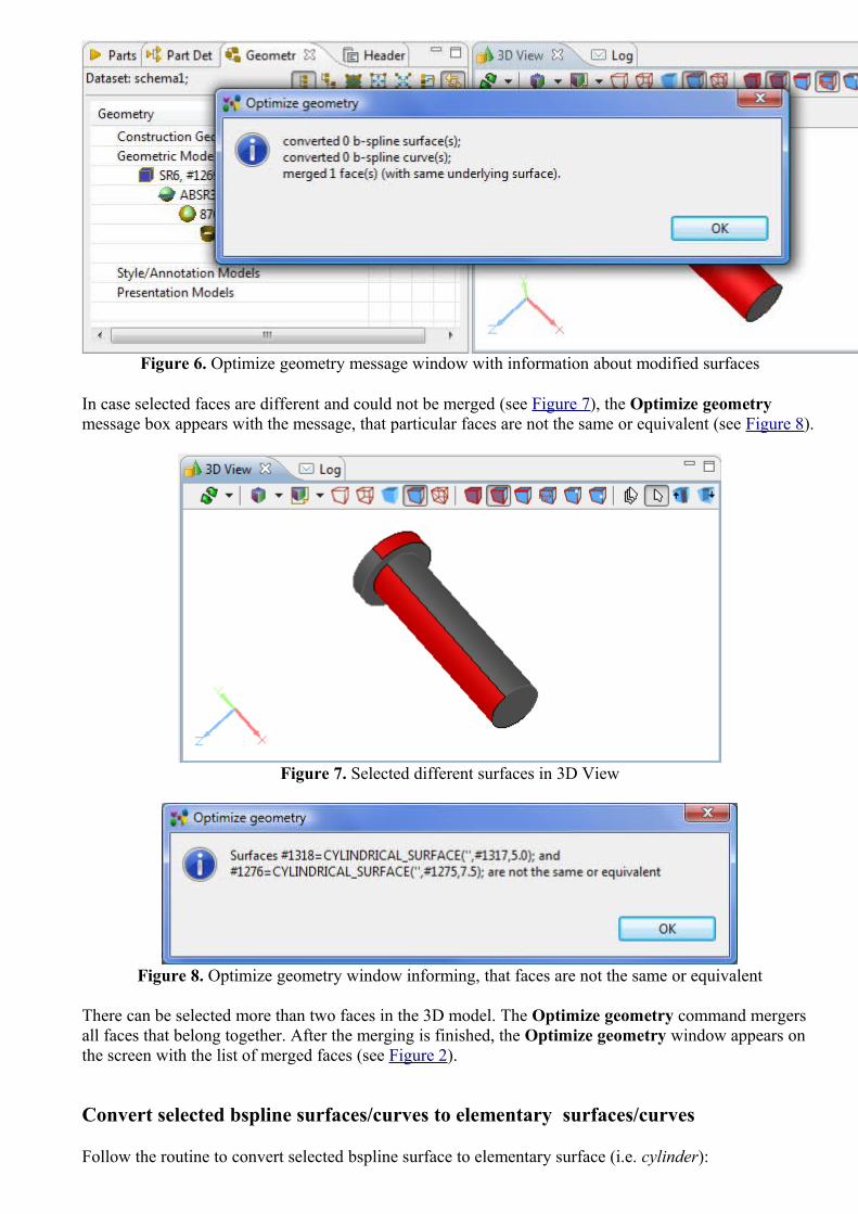
Figure 6. Optimize geometry message window with information about modified surfaces
In case selected faces are different and could not be merged (see Figure 7), the Optimize geometry message box appears with the message, that particular faces are not the same or equivalent (see Figure 8).
Figure 7. Selected different surfaces in 3D View
Figure 8. Optimize geometry window informing, that faces are not the same or equivalent
There can be selected more than two faces in the 3D model. The Optimize geometry command mergers all faces that belong together. After the merging is finished, the Optimize geometry window appears on the screen with the list of merged faces (see Figure 2).
Convert selected bspline surfaces/curves to elementary surfaces/curves
Follow the routine to convert selected bspline surface to elementary surface (i.e. cylinder):

• Ensure the Normal + Face/Surface Selection Mode is turned On. Note. In case the bspline curve, turn On the Edge/Curve Selection Mode.
• Select a bspline surface in the 3D View. The type of selected geometry is visible in the left bottom corner of the page (see Figure 9).
Figure 9. Selected Bspline surface
• Right click and select Optimize geometry menu item in the appeared context sensitive menu. • The message window Optimize geometry appears on the screen, informing, what number of faces
were modified by merging (see Figure 10). Click OK button to close the window.
Figure 10. Optimize geometry message window with information about modified surfaces
• Select the same surface in the 3D View. The current surface type with available data (i.e hash number and radius) is displayed in the left bottom corner of the page (see Figure 11).

Figure 11. Converted surface
To top
Copyright © 2010-2011 LKSoftWare GmbH. All Rights Reserved.JSDAI is a registered trade mark of LKSoftWare GmbH.
9.2.13. Re-triangulateOn the initial opening of a 3D model, the optimized triangulation is applied. It takes less time and is sufficient for reviewing of the hole model in the overview mode. When the user zooms in (moves the viewpoint closer to the model) it is apparent that the features are faceted (see Figure 1 on the left). To get a smooth 3D model view for the current viewpoint, IDA-STEP introduces the Retriangulate command, which can be executed by pressing the Retraingulate button in the 3D View tool bar. Note. If the user zooms in more and the view looks faceted again, the user can repeat the re-triangulation command.

Figure 1. 3D model view before re-triangulation and after
In case of a complex assembly, the triangulation may take more time. During the triangulation process the Progress Information window with a message 'Retriangulate current shape' appears on the screen (see Figure 2).
Figure 2. Progress Information window
To top
Copyright © 2012 LKSoftWare GmbH. All Rights Reserved.JSDAI is a registered trade mark of LKSoftWare GmbH.
9.2.14.1. Datum FeatureA datum feature in IDA-STEP is the actual surface component to establish a datum (points, lines, surfaces, planes, cylinders (see Figure 1) and etc., from which a location or geometric relationships of other features may be established or related).

Figure 1. Datum feature of surface ('A') and feature of size of two cylinders 2 x ('B')
Create datum feature
Follow the routine to create a datum feature:
• Point with a mouse on a surface component in the 3D View. Note. The selected point (even if no point selection mode is switched on) will be assumed as a start point of the leader line of the datum feature to be created.
• Right click and select Datum Feature item in the appeared context sensitive menu. • The Create Datum Feature wizard page appears in the GD&T view area. Enter needed data
in the wizard fields and click Create button. For more information see Create Datum Feature Wizard.
The datum feature is created and the datum feature symbol appears in the 3D View (see Figure 1). The leader line of the created datum feature starts at the point, the user clicked while selecting a surface component.
Move leader line
There is a possibility to move a datum feature leader line with symbol on the selected datum feature surface and modify leader line:
• Click with a mouse on the datum feature symbol. Two points on the leader lines are highlighted.• Click with a mouse on the point:

• which is in contact with the datum feature object (i.e. plane) - to change the datum feature symbol position on the datum feature.
• which is in contact with the block - to modify leader line.• Drag with a mouse to the desired direction. Release the mouse button to set the position.
To top
Copyright © 2010-2012 LKSoftWare GmbH. All Rights Reserved.JSDAI is a registered trade mark of LKSoftWare GmbH.
9.2.14.2. Datum TargetA Datum Target in IDA-STEP is a specified point, line or area on a part that is used in establishing a datum.
Create datum target
Follow the routine to create a datum target in the 3D View:
• Ensure the Vertex/point or Point on Edge or Surface Selection Mode is turned On in the 3D View tool bar.
• Point with a mouse on a geometry model on the area the datum target to be created. • Right click and select Datum Target item in the appeared context sensitive menu. • Select an item in the appeared of sub menu to open a particular datum target creation wizard in the
GD&T view details area: • Point Datum Target - to open the Create Target Point Wizard. The Figure 1 displays,
how the created datum target (point) is presented on the geometry model in the 3D View.
Figure 1. Datum target point with leader line and symbol
• Line Datum Target - to open the Create Target Straight Line Wizard. The Figure 2 displays, how the created datum target (line) is presented on the geometry model in the 3D View.

Figure 2. Datum target straight line with leader line and symbol
• Circle Datum Target - to open the Create Target Circle Wizard). The Figure 3 displays, how the created datum target (circle) is presented on the geometry model in the
3D View.
Figure 3. Datum target circle with leader line and symbol
• Circular Curve Datum Target - to open the Create Target Circular Curve Wizard. The Figure 4 displays, how the created datum target (circular curve) is presented on the geometry model in the 3D View.

Figure 4. Datum target circular curve with leader line and symbol
• Rectangle Datum Target - to open the Create Target Rectangle Wizard. The Figure 5 displays, how the created datum target (rectangle) is presented on the geometry model in the 3D View.
Figure 5. Datum target rectangle with leader line and symbol
Change location of datum target
To change location of a datum target start point (selected point/circle/line/rectangle on a surface, or surface component):
• Click with a mouse on the datum target symbol of an applicable datum target. Two points on the leader lines are highlighted (see Figure 6).
• Click with a mouse on the point, which is located on the datum target referenced surface or edge (the contact point or area).
• Drag with a mouse to the desired direction to change a location of the selected datum target. Release the mouse button to set the location (see Figure 6 b - the location of the datum target (rectangle) is changed).

a) b)
Figure 6. a) Selected datum target leader line and symbol with highlighted dragging points, b) changed location of datum target (rectangle)
Change datum target symbol position
To change position of a datum target symbol (end point of a leader line):
• Click with a mouse on the datum target symbol. Two points on the leader lines are highlighted (see Figure 6b).
• Click with a mouse on the point, which is in contact with the datum target symbol.• Drag with a mouse to the desired direction. Release the mouse button to set the position (see
Figure 7).

Figure 7. Datum target point with leader line and symbol, which position was changed
To top
Copyright © 2010-2011 LKSoftWare GmbH. All Rights Reserved.JSDAI is a registered trade mark of LKSoftWare GmbH.
9.2.14.3. Datum SystemA Datum system in IDA-STEP is a group of two or more separate datums used as a combined reference for a toleranced feature. Note. A datum system may be comprised of a single datum.
Create datum system
In order to create a datum system, at least one datum feature should exist (how to create datum feature, see Datum Feature -> Create datum feature).Follow the routine to create a datum system in the 3D View:
• Right click on the 3D View area. The context sensitive menu appears. • Select Datum System menu item. The Create Datum System wizard appears in the
GD&T view details area. How to manipulate with the wizard, see Clause Create Datum System Wizard.
• After the creation, a new entry of the datum system appears in the GD&T view table. Press on the datum system entry to view presentation in the 3D View (see Figure 1).

Figure 1. Selected datum system entry in GD&T view is highlighted in 3D view (all included datums are highlighted)
To top
Copyright © 2011 LKSoftWare GmbH. All Rights Reserved.JSDAI is a registered trade mark of LKSoftWare GmbH.
9.2.14.4. Geometric Tolerances
In the 3D View geometric tolerance values are displayed in feature control frames, connected with the shape feature with a leader line (see Figure 1). In case the leader line is connected with a surface, the terminator symbol is a dot, in other cases (edge, vertex point), the terminator symbol is an arrow.

Figure 1. Single feature control frame of geometric tolerance (position)
Create Geometric Tolerance
Follow the routine to create a geometrical tolerance for selected geometry component:
• Select an applicable geometry component in the 3D View. Note. To create a geometric tolerance for two or more geometry components, press CTRL key and point with a mouse on appropriate components.
• Right click and select Geometric Tolerance item in the appeared context sensitive menu. • The Create Geometric Tolerance wizard appears in the GD&T view area. • Enter needed parameters into the wizard fields and press the Create button. For more information
see Create Geometric Tolerance Wizard.
The created tolerance feature control frame with the entered data appears in the 3D View (see an example in Figure 1). Note. In case the geometry tolerance annotation is the first annotation for the selected feature, the start point of the leader line of the created feature control frame is the point, which a user points for selecting a component. In case a datum feature is created before or after a geometric tolerance creation, the annotations of a datum feature and a geometric tolerance are grouped (see Figure 2). If a group of geometric tolerances is created for the same feature, annotations of these geometric tolerances are combined (see Figure 3). In case the composite geometric tolerance is created, the first compartment of the tolerance frame is merged (see Figure 4).

Figure 2. Grouped annotations (datum feature and coaxiality tolerance)
Figure 3. Combined annotation (position tolerance for 8 holes) with highlighted related surfaces

Figure 4. Composite geometric tolerance annotation frame with merged first compartment
Move Geometric Tolerance Annotation
When clicking on the feature control frame of a geometric tolerance, the control points are highlighted on the annotation lines (see purple points in Figure 1). The point, which is on the selected feature (edge, surface) can be moved along this feature. Note. If the tolerance is applied to more than one component, this point can be moved along all selected features. Another point, which is located on the feature control frame, can be moved up and down, left and right to adjust an applicable feature control frame position. Note. In case of projected tolerance, the user can drag only on one side/edge, where projection end is specified.
To top
Copyright © 2010-2011 LKSoftWare GmbH. All Rights Reserved.JSDAI is a registered trade mark of LKSoftWare GmbH.
9.2.14.5. DimensionsDimensioning is the process of adding measurement annotation to a geometry object. The dimensions, created in IDA-STEP GD&T view, are presented on a geometry model in the 3D View. The following dimensions can be created in IDA-STEP:
• Size (radius, diameter, length): • Radius dimension (see Figure 1). The letter symbol R precedes the dimension value of a
radius. The single terminator is used for presentation of radius dimension. It is indicated at the intersection of the dimension line and an arc. The arrowed head can be either inside or outside the outline of the feature (see Figure 1 a). In case the radius dimension goes outside of a feature (cylinder, arc, cone, sphere) it is attached to, the extra extension arc is added, which connects a dimension line of radius and closest point on the feature. (see Figure 1 b).

a) b)
Figure 1. Radius dimension presentation in 3D View: a) radius dimension inside outline (i.e. 'R12') and radius limit dimension outside outline (i.e. 'R12 min.'); b) radius dimension with extra extension arc
• Diameter dimension (see Figure 2). The graphical symbol precedes the dimensional∅ value. In case of the Spherical diameter dimension, the S letter precedes the symbol . ∅

a) b)
Figure 2. Diameter dimension presentation in 3D View: a) cylinder/circle diameter dimension, b) spherical diameter dimension
Diameter dimension in IDA-STEP can be presented in two different ways (see Figure 3):
1. with two parallel leader curves, and2. with only one leader curve in line with the diameter axis. Note. In case an annotation plane is in-
line with a centre line of a circle/cylinder, this presentation is not possible, a dimension is presented with projection curves.
The default presentation of a diameter dimension is controlled via GD&T preferences by selecting a particular radio button: always with projection curves or without projection curves when possible (see Preferences -> GD&T -> Annotation Styles ). The instantaneous presentation of the diameter dimension can be changed directly in the 3D View by using CTRL key:
• Press CTRL key. • Select a diameter dimension annotation in the 3D View and drag the annotation using a mouse
button. • Release CTRL key and the mouse button.
Note. The presentation of the diameter dimension annotation will be changed to the default as soon as the
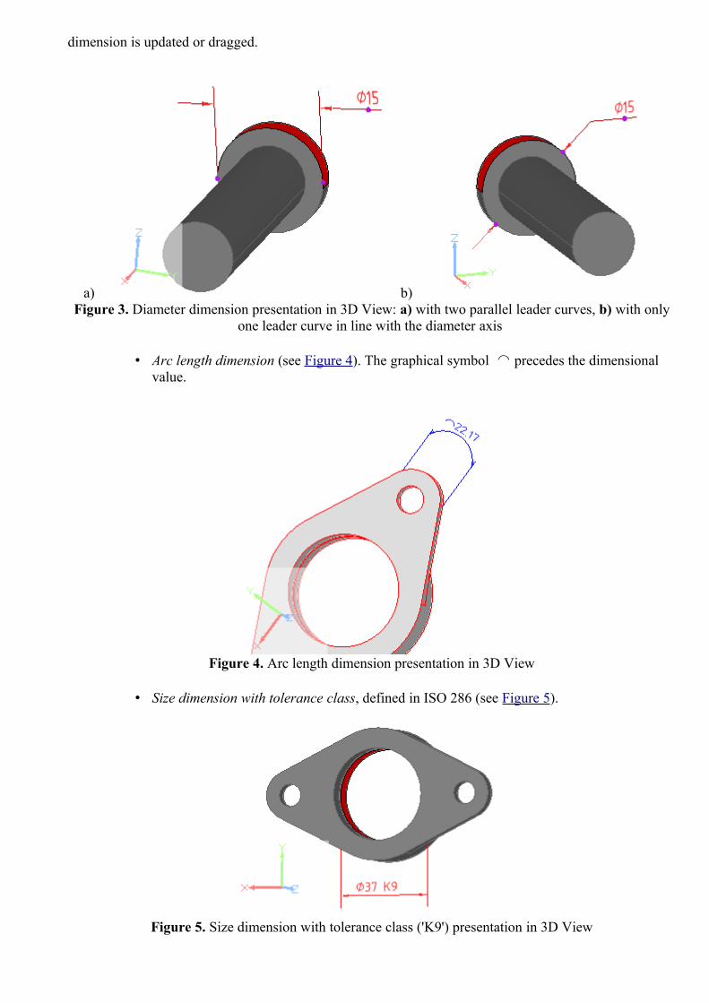
dimension is updated or dragged.
a) b) Figure 3. Diameter dimension presentation in 3D View: a) with two parallel leader curves, b) with only
one leader curve in line with the diameter axis
• Arc length dimension (see Figure 4). The graphical symbol precedes the dimensional⌒ value.
Figure 4. Arc length dimension presentation in 3D View
• Size dimension with tolerance class, defined in ISO 286 (see Figure 5).
Figure 5. Size dimension with tolerance class ('K9') presentation in 3D View

• Distance dimensions (see Figure 6).
a) b)
Figure 6. Presentation of distance dimensions in 3D View: a) between two vertex points and b) between two planes
• Angular: • Angular dimension (see Figure 7). The graphical symbol ° follows the dimensional value.
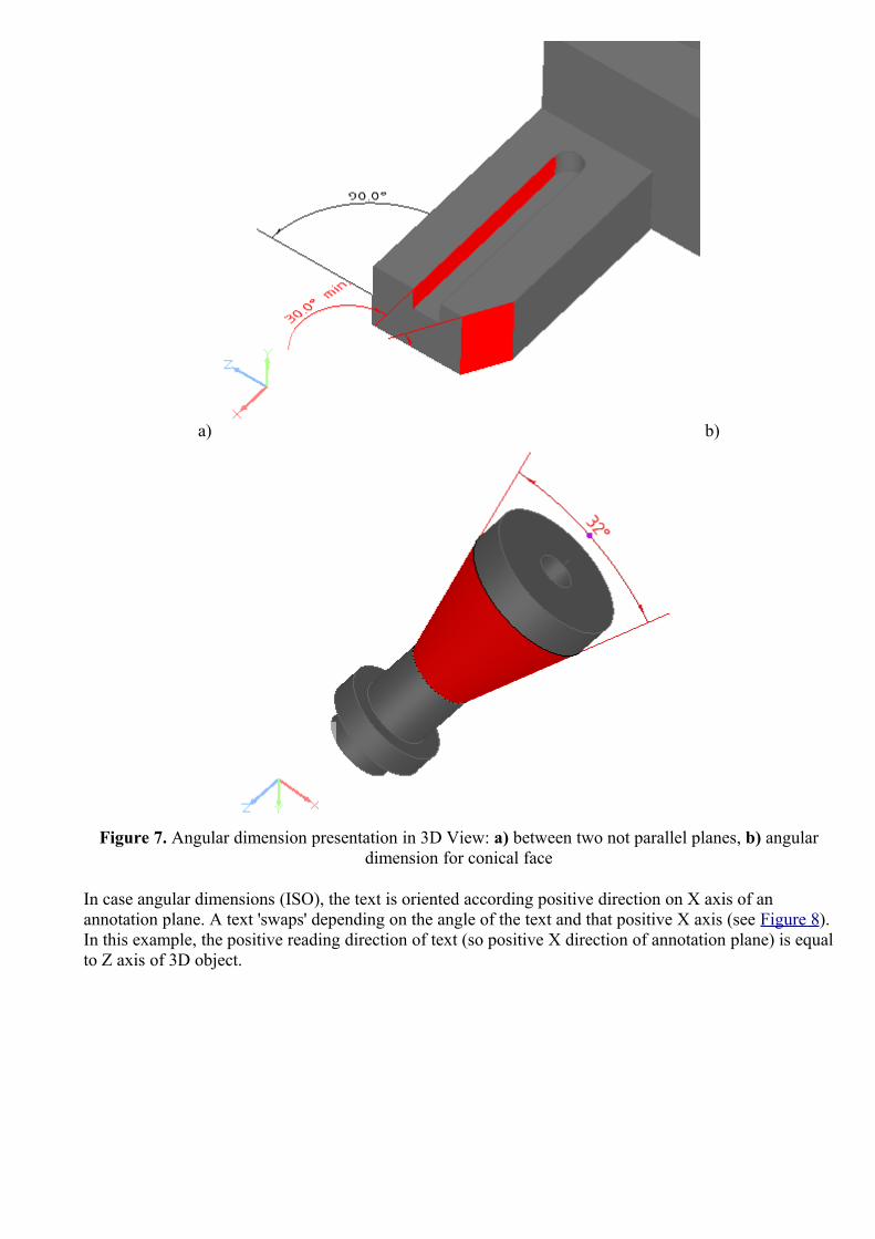
a) b)
Figure 7. Angular dimension presentation in 3D View: a) between two not parallel planes, b) angular dimension for conical face
In case angular dimensions (ISO), the text is oriented according positive direction on X axis of an annotation plane. A text 'swaps' depending on the angle of the text and that positive X axis (see Figure 8). In this example, the positive reading direction of text (so positive X direction of annotation plane) is equal to Z axis of 3D object.

Figure 7. Orientation of angular dimension (ISO)
In case an annotation ends on the feature, the projection lines of this annotation are skipped (see Figure 9).
Figure 9. Annotation with skipped projection line (no projection line on the left side of annotation)
Create Dimension
To create a linear or an angular dimension:
• Select an applicable surface element on a geometry object by pointing with a mouse. • Right click and select the Dimension -> Angle/ Size/ Distance item in the appeared
context menu. Note. In case there is no possibility to create any dimension for the selected geometry element, the New Dimension sub menu items are disabled.
• The Angular/Size Dimension/Distance wizard appears in the GD&T view details area (see Angular/Distance/Size Dimension Wizard).
The created dimension is displayed in the 3D View (dimension text, line and extension line). To move dimension annotation lines:
• Click with a mouse on the annotation text area. Note. To turn annotation into editing mode, the particular selection modes should be switched on:

• In case the Wire Frame and Solid or Solid, or Triangle Style is currently set On, the Face/Surface or Edge/Curve Selection Mode should be switched On.
• In case the Wire Frame or Wire Frame with Hidden Line Remove Style is currently switched On, the Edge/Curve selection mode should be switched On.
• Selection points are highlighted on the annotation lines. To adjust an applicable annotation line position, click with a mouse on a control point and drag the mouse into needed direction.
For more information see GD&T -> Dimensions.
To top
Copyright © 2010-2012 LKSoftWare GmbH. All Rights Reserved.JSDAI is a registered trade mark of LKSoftWare GmbH.
9.2.14.6. Annotation PlaneAn annotation plane in IDA-STEP is a conceptual plane, which contains annotations.Follow the routine to create an annotation plane in the 3D View:
• Select a planar surface in the 3D View to create an annotation plane, which is on the selected surface (see Figure 1). Note. It is not required selection. In case no planar surface is selected, more parameters have to be entered manually.
• Right click and select the New Annotation Plane item in the appeared context sensitive menu . • The Annotation Plane wizard appears in the GD&T view (see Annotation Plane Wizard).
Figure 1. Selected surface on which annotation plane should be created
The created annotation plane is not visible in the 3D View. To view the created annotation plane, select the recently created annotation plane entry in the GD&T view table. The selected annotation plane is highlighted in the 3D View (see Figure 2). Note. An annotation plane is defined by Cartesian point (origin point of annotation plane) and three vectors. Those three axes are shown at the origin point of the annotation plane in the 3D View. The size of axes is determined by the 3D view preference Coordinate system size (refer Clause Preferences -> 3D View). Axes are visible for an annotation plane only when it is selected.

Figure 2. Created annotation plane and coordinate axes at origin point of annotation plane
In most cases the annotation plane is automatically created, while creating some GD&T element, which has an association with an annotation plane and there is no suitable previously created annotation plane. See Figure 3 - where an annotation plane ('AP1') is created for a datum feature ('A' and 'B' reuses the same annotation plane), size dimension and geometric tolerance annotation; and Figure 4, where a new annotation plane ('AP2') is created for a datum feature 'C', size dimension and position tolerance. Note. In these examples the origin point of annotation plane is hidden inside geometry, so the coordinate axes of the selected annotation plane are not visible.
Figure 3. Annotation plane 'AP1' with the related annotation (both highlighted in 3D View)

Figure 4. Active annotation plane 'AP2' with related annotations
See also: GD&T -> Annotation Plane; 3D Viewer -> Style/Annotation Model -> Change active and bring to front Annotation Plane
To top
Copyright © 2010-2011 LKSoftWare GmbH. All Rights Reserved.JSDAI is a registered trade mark of LKSoftWare GmbH.
9.2.14.7. Text AnnotationA Text Annotation in IDA- STEP is a 3D annotation with a free text, one or several lines (see Figure 1).
Figure 1. Text annotations in 3D View (one line and three lines)
Create text annotation
Follow the routine to create a text annotation in the 3D View:
• Point with a mouse on an applicable geometry component in the 3D View. Note. The selected point (even if no point selection mode is switched on) will be assumed as a start point of the leader line of the text annotation to be created.

• Right click and select Text Annotation item in the appeared context sensitive menu. • The Create Text Annotation wizard page appears in the GD&T view area. Enter needed data
in the wizard fields and click Create button. For more information see Create Text Annotation Wizard.
The text annotation is created and appears in the 3D View (see Figure 1). The leader line of the created text annotation starts at the point, the user clicked while selecting a geometry component.
Move leader line
There is a possibility to move a text annotation leader line on the selected feature/entire shape and modify leader line:
• Click with a mouse on the text annotation. Two points on the leader lines are highlighted.• Click with a mouse on the point:
• which is in contact with the feature object the text annotation is applied to (i.e. line) - to change the text annotation position on the feature.
• which is in contact with the text - to modify leader line.• Drag with a mouse to the desired direction. Release the mouse button to set the position.
Note. In case a text annotation is applied to the entire shape, the point of a leader line, which is in a contact with the shape, can be moved all over the entire shape.
To top
Copyright © 2012 LKSoftWare GmbH. All Rights Reserved.JSDAI is a registered trade mark of LKSoftWare GmbH.
9.2.14.8. Shape AspectA shape aspect is an element of the shape of a product. A Composite Shape Aspect in IDA-STEP is a shape aspect, that associates aspects of the product shape for a specific purpose.In the 3D View there is a possibility to create a single shape aspect and a composite shape aspect.
Create single shape aspect
To create a single shape aspect:
• Point with a mouse on any geometry element (point, line, plane and etc). • Right click and select the Shape Aspect item in the appeared context sensitive menu (see
Figure 1).

Figure 1. Selected plane and context sensitive menu item to create a shape aspect
The shape aspect is created for the selected geometry element. It is not visible any changes in the 3D View, but a new entry appears in the GD&T view table. For more information about the shape aspects in the GD&T view, see Clause GD&T -> Shape Aspects.
Create composite shape aspect
To create a composite shape aspect:
• Select two or more geometry elements on the geometry object in the 3D View. • Right click and select the Shape Aspect item in the appeared context sensitive menu (see
Figure 2).
Figure 1. Selected three cylinders and context sensitive menu item to create a composite shape aspect

A new entry of the composite shape aspect (labeled with CS letters and a number) in the GD&T view table. Note. It is additionally created a shape aspect for each selected geometry element, which has no associated shape aspect. For more information about the composite shape aspect, see Clause GD&T -> Composite Shape Aspect.
To top
Copyright © 2010-2011 LKSoftWare GmbH. All Rights Reserved.JSDAI is a registered trade mark of LKSoftWare GmbH.
9.2.14.9. Constructive Geometry Elements
The 3D View displays constructive geometry elements, which are assigned to construction geometry models, displayed in Geometry Details view. IDA-STEP presents possibility to create simple constructive geometry elements, such as line and plane, and derived shape elements (apex, symmetry point, line and plane, common line and plane, intersection, offset, extension, perpendicular line and plane, tangent plane ). Those elements are created by using wizards, which appear in the GD&T view. Created constructive geometry elements are displayed in all above mentioned views:
• 3D View - on the geometry object and highlighted together with the referenced geometry element.
• Geometry Details view - under Construction Geometry Models -> Model branch for the currently active model. In case no active model is selected or there are no models at all, a new model is created under the Construction Geometry Models branch. Selection of the created constructive geometry element initiates a highlighting in the GD&T view and in the 3D View.
• GD&T view - a new entry appears in the table.If this entry is selected, the particular wizard dialog appears in the details area under the table and the element is highlighted in the 3D View together with referenced geometry element, and in the Geometry Details view.
For more information, see Geometry Details -> Construction Geometry Models, GD&T -> Constructive Geometry.
To top
Copyright © 2010 LKSoftWare GmbH. All Rights Reserved.JSDAI is a registered trade mark of LKSoftWare GmbH.
9.2.14.9.1. ApexAn apex in IDA-STEP is the highest vertex of the cone.To create an apex in the 3D View:
• Select a cone surface of the geometry object. • Right click and select the New Constructive Geometry -> Apex item in the appeared context
sensitive menu.
After the menu item is selected the apex is instantly created. Note. The apex can be rather far away from the cone face. In cases the resulting apex is not visible in the
3D View, it is recommended to zoom out the 3D part to view the apex point.

Figure 1. Apex (selection in GD&T view) - highlighted in Geometry Details view under the construction geometry model branch, GD&T view (table and wizard) and 3D View, together with the referenced cone
surface
For more information, see GD&T -> Create Apex.
To top
Copyright © 2010-2011 LKSoftWare GmbH. All Rights Reserved.JSDAI is a registered trade mark of LKSoftWare GmbH.
9.2.14.9.2. Symmetry AxisA symmetry axis in IDA-STEP is a center line of a cylinder, cone, toroid and revolution.To create a symmetry axis in the 3D View:
• Select a cylinder, cone, toroid or revolution. • Right click and select the New Constructive Geometry -> Symmetry Axis item in the appeared
context sensitive menu.
After the menu item is selected the symmetry axis for the selected geometry element is instantly created.

Figure 1. Symmetry axis of cylinder (selection in GD&T view) - highlighted in Geometry Details view under the construction geometry model branch, GD&T view (table and wizard) and 3D View, together
with the referenced cylinder surface
See also GD&T -> Create Symmetry Axis. To top
Copyright © 2010-2011 LKSoftWare GmbH. All Rights Reserved.JSDAI is a registered trade mark of LKSoftWare GmbH.
9.2.14.9.3. Symmetry PlaneA symmetry plane in IDA-STEP is a center plane between two planar surfaces.To create a symmetry plane in the 3D View:
• Select two planar surfaces. • Right click and select the New Constructive Geometry -> Symmetry Plane item in the appeared
context sensitive menu.
After the menu item is selected the symmetry plane of selected planar surfaces is instantly created.

Figure 1. Symmetry plane (selection in GD&T view) - highlighted in Geometry Details view under the construction geometry model branch, GD&T view (table and wizard) and 3D View, together with the
referenced planes
See also GD&T -> Symmetry Plane.
To top
Copyright © 2010-2011 LKSoftWare GmbH. All Rights Reserved.JSDAI is a registered trade mark of LKSoftWare GmbH.
9.2.14.9.4. Symmetry PointA symmetry point in IDA-STEP is a center point of a circle or a sphere.To create a symmetry point in the 3D View:
• Select a circle line or sphere surface. • Right click and select the New Constructive Geometry -> Symmetry Point item in the appeared
context sensitive menu.
After the menu item is selected the symmetry point of the selected circle or sphere is instantly created.

Figure 1. Symmetry point (selection in GD&T view) - highlighted in Geometry Details view under the construction geometry model branch, GD&T view (table and wizard) and 3D View, together with the
referenced circle
See also GD&T -> Create Symmetry Point.
To top
Copyright © 2010-2011 LKSoftWare GmbH. All Rights Reserved.JSDAI is a registered trade mark of LKSoftWare GmbH.
9.2.14.9.5. Common LineA common line in IDA-STEP is a line, which goes through two selected points.To create a common line in the 3D View:
• Select two points on a geometry object. • Right click and select the New Constructive Geometry -> Common Line item in the appeared
context sensitive menu.
After the menu item is selected the common line through the selected points is instantly created.

Figure 1. Common line (selection in GD&T view) - highlighted in Geometry Details view under the construction geometry model branch, GD&T view (table and wizard) and 3D View, together with
referenced points
See also GD&T -> Create Common Line.
To top
Copyright © 2010-2011 LKSoftWare GmbH. All Rights Reserved.JSDAI is a registered trade mark of LKSoftWare GmbH.
9.2.14.9.6. Common PlaneA common plane in IDA-STEP is a plane, which goes through:
• two lines, • a line and a point.
To create a common plane in the 3D View:
• Select two lines or a line and a point on a geometry object. • Right click and select the New Constructive Geometry -> Common Plane item in the appeared
context sensitive menu.
After the menu item is selected the common plane through the selected elements is instantly created.

Figure 1. Common plane (selection in GD&T view) - highlighted in Geometry Details view under the construction geometry model branch, GD&T view (table and wizard) and 3D View, together with
referenced two lines
See also GD&T -> Create Common Plane.
To top
Copyright © 2010-2011 LKSoftWare GmbH. All Rights Reserved.JSDAI is a registered trade mark of LKSoftWare GmbH.
9.2.14.9.7. IntersectionAn intersection in IDA-STEP is an intersection between two elements:
• two lines - the result is a Cartesian point, which is an intersection of two non parallel lines. • two planes - the result is a line, which is an intersection of two non parallel planes. • plane and cylinder -the result is a circle, an ellipse or a line:
• in case the selected plane goes across the cylinder, an intersection is a circle or an ellipse. • in case the selected plane goes along the cylinder, an intersection is a line (the result can be
one or two lines). • plane and line - the result is a Cartesian point, which is an intersection of non parallel objects -
line and plane. • line and cylinder - the result is a Cartesian point, which is an intersection of non parallel objects -
line and cylinder. • line and sphere - the result is a Cartesian point, which is an intersection of line and sphere. • plane and sphere - the result is a circle or a Cartesian point:
• in case the selected plane crosses the sphere, an intersection is a circle. • in case the selected plane is a tangent plane for the selected sphere, an intersection is a
Cartesian point.

To create an intersection in the 3D View:
• Select two elements (see the above list) on a geometry object. • Right click and select the New Constructive Geometry -> Intersection item in the appeared
context sensitive menu.
After the menu item is selected the intersection of selected elements is instantly created.
Figure 1. Intersection line (selection in GD&T view) - highlighted in Geometry Details view under the construction geometry model branch, GD&T view (table and wizard) and 3D View, together with
referenced planes
See also GD&T -> Create Intersection.
To top
Copyright © 2010-2011 LKSoftWare GmbH. All Rights Reserved.JSDAI is a registered trade mark of LKSoftWare GmbH.
9.2.14.9.8. OffsetAn offset in IDA-STEP is an object (plane, line or point) whose shape parallels the shape of the original object. To create an offset in the 3D View:
• Select an applicable object. • Right click and select the New Constructive Geometry -> Offset item in the appeared context
sensitive menu. • Further details, how to set parameters for an offset, see GD&T -> Create Offset.

Figure 1. Offset plane (selection in GD&T view) - highlighted in Geometry Details view under the construction geometry model branch, GD&T view (table and wizard) and 3D View, together with
referenced plane
To top
Copyright © 2010-2011 LKSoftWare GmbH. All Rights Reserved.JSDAI is a registered trade mark of LKSoftWare GmbH.
9.2.14.9.9. Perpendicular LineA perpendicular line in IDA-STEP is a line which maintains a 90-degree angle to a particular object and goes through the specified point. The following input objects can be selected for the creation of a perpendicular line:
• plane and point - to create a line, which is perpendicular to the selected plane and goes through the specified point.
• sphere and point - to create a line, which is a sphere center axis through the specified point.• cylinder ant point - to create a line, which is perpendicular to the center axis of the selected
cylinder and goes through the specified point.• cone and point - to create a line, which is perpendicular to the surface of the selected cone at the
specified point.
To create perpendicular line in the 3D View:
• Select two applicable object (see the list above for available combination). • Right click and select the New Constructive Geometry -> Perpendicular line item in the
appeared context sensitive menu.
After the menu item is selected a perpendicular line is instantly created.
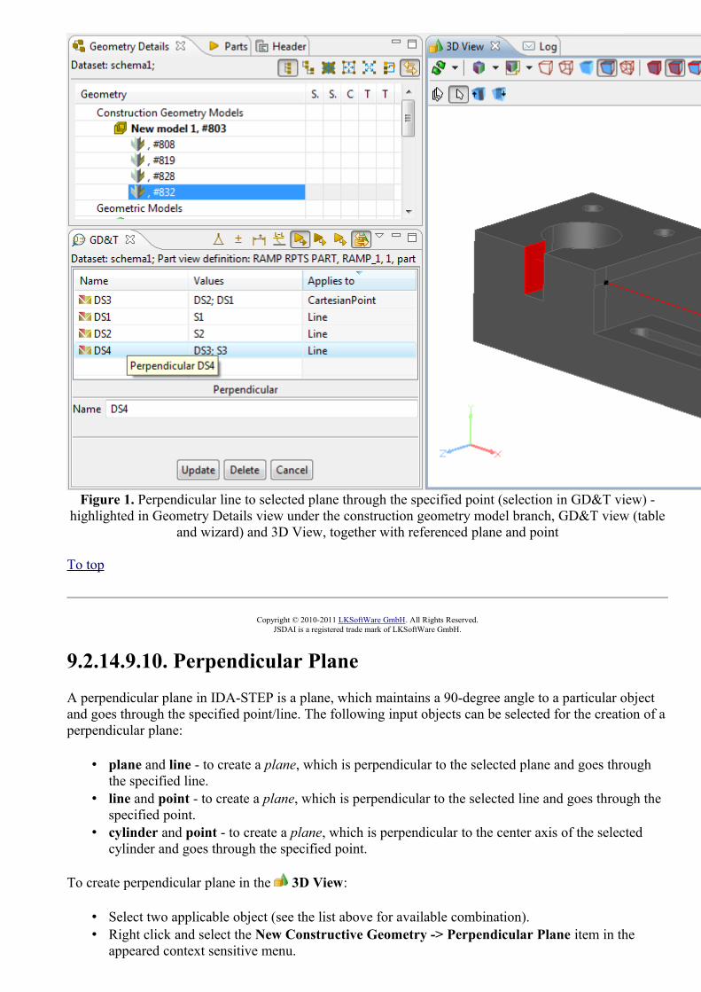
Figure 1. Perpendicular line to selected plane through the specified point (selection in GD&T view) - highlighted in Geometry Details view under the construction geometry model branch, GD&T view (table
and wizard) and 3D View, together with referenced plane and point
To top
Copyright © 2010-2011 LKSoftWare GmbH. All Rights Reserved.JSDAI is a registered trade mark of LKSoftWare GmbH.
9.2.14.9.10. Perpendicular PlaneA perpendicular plane in IDA-STEP is a plane, which maintains a 90-degree angle to a particular object and goes through the specified point/line. The following input objects can be selected for the creation of a perpendicular plane:
• plane and line - to create a plane, which is perpendicular to the selected plane and goes through the specified line.
• line and point - to create a plane, which is perpendicular to the selected line and goes through the specified point.
• cylinder and point - to create a plane, which is perpendicular to the center axis of the selected cylinder and goes through the specified point.
To create perpendicular plane in the 3D View:
• Select two applicable object (see the list above for available combination). • Right click and select the New Constructive Geometry -> Perpendicular Plane item in the
appeared context sensitive menu.

After the menu item is selected a perpendicular plane is instantly created.
Figure 1. Perpendicular plane to plane surface through line (selection in GD&T view) - highlighted in Geometry Details view under the construction geometry model branch, GD&T view (table and wizard)
and 3D View, together with referenced plane and line
To top
Copyright © 2010-2011 LKSoftWare GmbH. All Rights Reserved.JSDAI is a registered trade mark of LKSoftWare GmbH.
9.2.14.9.11. ExtensionAn extension in IDA-STEP is an extension of a plane.To create an extension in the 3D View:
• Select a planar surface on the geometry object. • Right click and select the New Constructive Geometry -> Extension item in the appeared
context sensitive menu.
After the menu item is selected an extension of the selected plane is instantly created.

Figure 1. Plane extension (selection in GD&T view) - highlighted in Geometry Details view under the construction geometry model branch, GD&T view (table and wizard) and 3D View, together with
referenced plane
See also GD&T -> Create Extension.
To top
Copyright © 2010-2011 LKSoftWare GmbH. All Rights Reserved.JSDAI is a registered trade mark of LKSoftWare GmbH.
9.2.14.9.12. Tangent PlaneA tangent plane in IDA-STEP is a plane, that touches the selected object at the specified point. The following input objects can be selected for the creation of a tangent plane:
• cylinder and point - to create a plane that touches the selected cylinder at the specified point.• cone and point - to create a plane that touches the selected cone surface at the specified point. • sphere and point - to create a plane that touches the selected sphere at the specified point.
To create perpendicular plane in the 3D View:
• Select two applicable object (see the list above for available combination). • Right click and select the New Constructive Geometry -> Tangent Plane item in the appeared
context sensitive menu.
After the menu item is selected a tangent plane is instantly created.

Figure 1. Tangent plane of a cylinder at specified point (selection in GD&T view) - highlighted in Geometry Details view under the construction geometry model branch, GD&T view (table and wizard)
and 3D View, together with referenced cylinder and point
See also GD&T -> Create Tangent Plane .
To top
Copyright © 2010-2011 LKSoftWare GmbH. All Rights Reserved.JSDAI is a registered trade mark of LKSoftWare GmbH.
9.2.14.9.13. PointA point in IDA-STEP is a point for a construction geometry model, created using explicit entered geometric values.To create a point in the 3D View:
• Right click on the 3D View area.Or
• Select any point on the 3D surface or edge and right click. Note. The Vertex/Point or Point on Edge or Curve Selection Mode should be switched On.
• Select the Constructive Geometry -> Point item in the appeared context sensitive menu.• Further details, how to set parameters for a point, see GD&T -> Constructive Geometry -> New
Point. Note. In case the point on edge or surface was selected in the 3D View, all parameter values of that point are filled automatically.
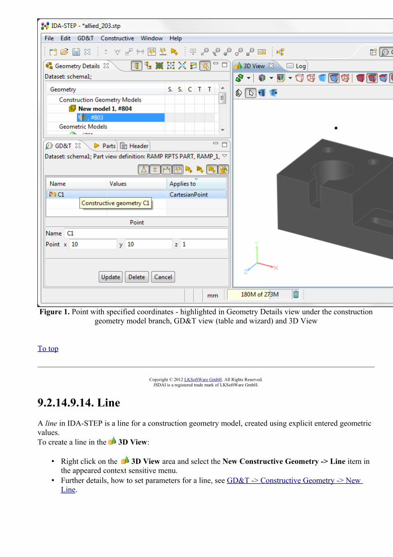
Figure 1. Point with specified coordinates - highlighted in Geometry Details view under the construction geometry model branch, GD&T view (table and wizard) and 3D View
To top
Copyright © 2012 LKSoftWare GmbH. All Rights Reserved.JSDAI is a registered trade mark of LKSoftWare GmbH.
9.2.14.9.14. LineA line in IDA-STEP is a line for a construction geometry model, created using explicit entered geometric values.To create a line in the 3D View:
• Right click on the 3D View area and select the New Constructive Geometry -> Line item in the appeared context sensitive menu.
• Further details, how to set parameters for a line, see GD&T -> Constructive Geometry -> New Line.

Figure 1. Line with specified point and direction (selection in GD&T view) - highlighted in Geometry Details view under the construction geometry model branch, GD&T view (table and wizard) and 3D
View
To top
Copyright © 2010-2011 LKSoftWare GmbH. All Rights Reserved.JSDAI is a registered trade mark of LKSoftWare GmbH.
9.2.14.9.15. PlaneA plane in IDA-STEP is a plane for a construction geometry model, created using explicit entered geometric values.To create a plane in the 3D View:
• Right click on the 3D View area and select the New Constructive Geometry -> Plane item in the appeared context sensitive menu.
• Further details, how to set parameters for a plane, see GD&T -> Constructive Geometry -> New Plane.

Figure 1. Plane through point and normal (selection in GD&T view) - highlighted in Geometry Details view under the construction geometry model branch, GD&T view (table and wizard) and 3D View
To top
Copyright © 2010-2011 LKSoftWare GmbH. All Rights Reserved.JSDAI is a registered trade mark of LKSoftWare GmbH.
9.2.14.10. Align OffsetAlign Offset is a function to align the offset of annotations on the same annotation plane (see Figure 1):
Figure 1. Dimension annotations on the same annotation plane

• Activate the 3D View.• Select the master annotation (see Figure 2a). Then select all the other ones that should use the
same offset as the master one (see Figure 2b).
a) b) Figure 2. a) Selected master annotation b) Selected all annotations to be aligned
• Right click and select Align Offset item in the appeared context sensitive menu (see Figure 3).
Figure 3. Align Offset item selected in context sensitive menu
The offset of annotations is aligned according to the master annotation offset (see Figure 4). The master annotation is highlighted in the 3D View.
Figure 4. Aligned offset of annotations (master annotation is highlighted)To top
Copyright © 2011 LKSoftWare GmbH. All Rights Reserved.JSDAI is a registered trade mark of LKSoftWare GmbH.

9.3.1. Datasets View
The Datasets window presents available datasets in the opened repository (see Figure 1). Datasets may have assigned types and a particular icon indicates a type of the dataset, for example:
• Parts,• / Persons and Organizations, • Tasks, • Zonal Breakdowns, • Part Details, • Product as Individual, • Stratum technology and etc.
Figure 1. Datasets window
To top
Copyright © 2006-2009 LKSoftWare GmbH. All Rights Reserved.JSDAI is a registered trade mark of LKSoftWare GmbH.
9.3.2. Creating Dataset
Follow the routine to create a new dataset in the Datasets window:
• Right click on the root node in the window. The context sensitive menu appears (see Figure 1).
Figure 1. Context sensitive menu, New Dataset menu item
• Select New dataset menu item. The Create New Dataset wizard window appears (see Figure 2):

Figure 2. Create New Dataset wizard window
• Enter a name of the dataset to be created into Name field. • Select a type of the dataset in the Type layout.• Click Finish button to create a dataset of the selected type.
• After the creation of the dataset is completed, the created dataset appears in the Datasets window.
To top
Copyright © 2006-2009 LKSoftWare GmbH. All Rights Reserved.JSDAI is a registered trade mark of LKSoftWare GmbH.
9.3.3. Renaming Dataset
Follow the routine to rename a dataset in the Datasets window:
• Right click on a dataset you want to rename. The context sensitive menu appears. • Select Rename menu item. The name of the dataset is selected:
• Enter new or edit the current dataset name. • Press Enter key.
• The selected dataset is renamed in the Datasets window.
To top

Copyright © 2006-2009 LKSoftWare GmbH. All Rights Reserved.JSDAI is a registered trade mark of LKSoftWare GmbH.
9.3.4. Removing Dataset
Follow the routine to remove an incorrect or redundant dataset from the Datasets window:
• Right click on a dataset you want to remove. The context sensitive menu appears. • Select Delete menu item. The selected dataset disappears from the Datasets window.
To top
Copyright © 2006-2009 LKSoftWare GmbH. All Rights Reserved.JSDAI is a registered trade mark of LKSoftWare GmbH.
9.4.1. Design Stack Models View
The Design Stack Models view (available by selecting in the main menu bar Window -> Show view -> Other then under PCB Layer Stack node) presents a list of design stack models (see Figure 1). The first column presents the row element - design stack model. Other columns contain data of the particular design stack model. The default column perspective contains the following columns:
• Id - an identifier of a design stack model. • Name - specifies the word or group of words by which the design stack model (in the role of
product) is referred to. • Id Owner - the assigned person or organization owns the design stack model (in the role of
product), and has final say over its disposition and any changes to it. • Creator - the design stack model (in the role of product) has been created by the assigned person
or organization. • Conductive layers - the number of conductive layers in the design stack model.• Total Thickness - the total thickness of the layers, which contain the current design stack model.
Figure 1. Design Stack Models view (default columns)
To top
Copyright © 2008-2009 LKSoftWare GmbH. All Rights Reserved.JSDAI is a registered trade mark of LKSoftWare GmbH.

9.4.2. Creating Design Stack Model
Follow the routine to create a new design stack model in the Design Stack Models view table (see Figure 1):
Figure 1. Design Stack Models view (with highlighted autorow)
• Select the autorow in the table (see Figure 1 highlighted cell in Id column). • Click on the selected autorow to enter in to the edit mode. • Enter an identifier for the new design stack model. • Press Enter key. A new record appears in the Design Stack Models view table (see Figure 2).
Figure 2. Created design stack model element in the table.
To top
Copyright © 2008-2009 LKSoftWare GmbH. All Rights Reserved.JSDAI is a registered trade mark of LKSoftWare GmbH.
9.4.3. Editing Design Stack Model Data
Activate the Design Stack Models view. Select an applicable design stack model element in the table. You can edit the following:
• Enter the identifier into the Id column. • Enter the text, which defines the design stack model (in the role of product) name into the Name
column. • Assign an organization in the Id Owner and Creator columns by dragging and dropping an
applicable organization form the Persons and Organizations view.
You can not directly enter the value into the Conductive layers field. This attribute is derived and comes form the Stratums view. The value depends on the number of conductive layers entered in the Stratums

view for the particular design stack model element.Also you can not edit the Total Thickness column value, as it depends on values entered in the Stratums view table (thickness of layers of the particular design stack model).
To top
Copyright © 2008-2009 LKSoftWare GmbH. All Rights Reserved.JSDAI is a registered trade mark of LKSoftWare GmbH.
9.5.1. DocumentsA document is a logical document that serves as the identifier for a container for some product data.The Documents window presents a tree table with a hierarchy of documents, which are available for the selected dataset (see Figure 1). The default perspective contains the following columns:
• Id - an identifier of the document.• Name - specifies the word or group of words by which the document is referred to. • Description - specifies additional information about the document.
Figure 1. Documents window
To top
Copyright © 2006-2009 LKSoftWare GmbH. All Rights Reserved.JSDAI is a registered trade mark of LKSoftWare GmbH.
9.5.2. Document Hierarchy
The Id column in the Documents window presents the hierarchy of documents (see Figure 1):
• Root node - documents, files, file references. • Second level node - document versions. • Third level node - associated files and/or file references.
Figure 1. Document hierarchyTo top

Copyright © 2006-2009 LKSoftWare GmbH. All Rights Reserved.JSDAI is a registered trade mark of LKSoftWare GmbH.
9.5.3. Creating New DocumentFollow the routine to create a new document in the document hierarchy:
• Right click on an empty area of the Documents window. • Select the New Document menu item in the appeared context sensitive menu (see Figure 1).
Figure 1. New document menu item
• The new document appears as the root node in the tree with a new version node (see Figure 2).
Figure 2. New document with versionTo top
Copyright © 2006-2009 LKSoftWare GmbH. All Rights Reserved.JSDAI is a registered trade mark of LKSoftWare GmbH.
9.5.4. Adding VersionTo add a new version of a document:
• Right click on an applicable document node in the tree. • Select the Add Version menu item in the appeared context sensitivie menu (see Figure 1).

Figure 1. Add Version menu item
• The new version node appears under the selected document (see Figure 2).
Figure 2. New version node in the treeTo top
Copyright © 2006-2009 LKSoftWare GmbH. All Rights Reserved.JSDAI is a registered trade mark of LKSoftWare GmbH.
9.5.5. Adding FileThere is a possibility to add a file as a root element in the tree or assign a file to a particular document version.To add a file:
• Right click on the empty area of the Documents window or on an applicable document version.
• Select the Add File menu item in the appeares context sensitive menu (see Figure 1).
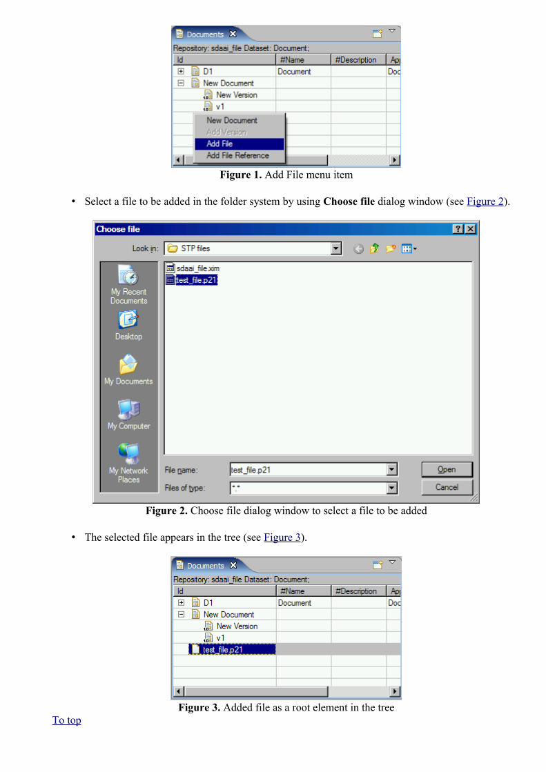
Figure 1. Add File menu item
• Select a file to be added in the folder system by using Choose file dialog window (see Figure 2).
Figure 2. Choose file dialog window to select a file to be added
• The selected file appears in the tree (see Figure 3).
Figure 3. Added file as a root element in the treeTo top

Copyright © 2006-2009 LKSoftWare GmbH. All Rights Reserved.JSDAI is a registered trade mark of LKSoftWare GmbH.
9.5.6. Adding File ReferenceThere is a possibility to add a file reference as a root element in the tree or assign file reference to a particular document version.To add file reference:
• Right click on an empty area of the Documents window or on an applicable document version node.
• Select the Add File Reference menu item in the appeared context sensitive menu (see Figure 1).
Figure 1. Add File Reference menu item
• Select the file to be added as a reference in the folder system by using Choose file dialog window (see Figure 2).

Figure 2. Choose file dialog window
• The associated file refernce appears in the tree (see Figure 3).
Figure 3. Added file refernece under the document version nodeTo top
Copyright © 2006-2009 LKSoftWare GmbH. All Rights Reserved.JSDAI is a registered trade mark of LKSoftWare GmbH.
9.6.1. FMECA View
The Failure mode specifies the manner by which a failure is observed; it generally describes the way the failure occurs.The Failure effect specifies immediate consequences of a failure on operation, function or functionality, or status of some item.The Criticality analysis is used to chart the probability of failure modes against the severity of their consequences.The Failure cause are defects in design, process, quality, or part application, which are the underlying cause of the failure or which initiate a process which leads to failure.
The FMECA (Failure Mode, Effects, and Criticality Analysis) view presents a table which

provides the maintenance of FMECA data (see Figure 1). The first column presents a hierarchy:
• Top node - a product part, for which the failure mode object may be associated as a child. • Second level node - failure mode, which can contain child failure modes and failure
causes. • Third and lower level nodes - associated failure modes and/or failure causes.
Note. The failure cause node can not have any child nodes.
Other table columns contain particular FMECA data for each failure mode and failure cause. The default column perspective contain the following columns:
• Local Effect - specifies the failure effect as it applies to the item under analysis. • Next Higher Assembly Effect - specifies the failure effect as it applies at the next higher
indenture level. • End Effect - specifies the failure effect at the highest indenture level or total system. • Severity - specifies the worst possible consequence of a failure classified by the degree of injury,
property damage, system damage and mission loss that could occur. • Failure Mode Class - specifies the class of the failure mode. Predefined values are 'Human error',
'Disassembly', 'External effect', 'Deterioration' and 'Lubrication failure'. • Failure Cause Class - specifies the classification items of the failure cause. Predefined values are:
'Design failure', 'Weakness failure', 'Manufacturing failure', 'Aging failure', 'Misuse failure' and 'Mishandling failure'.
• Preventive control (design provision) - specifies the actions available or that can be taken to negate or reduce the effect of a failure on a system.
• Probability - specifies a probability of the failure cause.• Detection Rating - specifies the detection of the condition which might lead to the failure. • Detection Method - specifies the method by which a failure can be discovered by the system
operator under normal system operation or by a maintenance crew carrying out a specific diagnostic action. The predefined values are: 'Alarm', 'Built in test', 'Non destructive examination', 'Vibration analysis', 'Particle analysis', 'Chemical analysis', 'Spectographic analysis', 'Visual', 'Audible' and 'Olfcatory'.
• RPN (Risk Priority Number) - provides an alternate evaluation approach to Criticality Analysis. The risk priority number provides a qualitative numerical estimate of design risk. RPN is defined as the product of three independently assessed factors: Probability, Detection Rating and Severity.
Figure 1. FMECA view
To top

Copyright © 2009 LKSoftWare GmbH. All Rights Reserved.JSDAI is a registered trade mark of LKSoftWare GmbH.
9.6.2. Creating Failure Mode
Follow the routine to create a new failure mode object in the FMECA view:
• Right click on a product part node to create a top level failure mode.
Or
• Right click on an applicable failure mode node in the tree to create a child failure mode object.
• Select the New failure mode menu item in the appeared context sensitive menu (see Figure 1).
Figure 1. Context sensitive menu with selected New failure mode menu item
The created failure mode object, named 'New failure mode', appears under the selected node (see Figure 2).
Figure 2. Created failure mode (highlighted)
To top
Copyright © 2009 LKSoftWare GmbH. All Rights Reserved.JSDAI is a registered trade mark of LKSoftWare GmbH.

9.6.3. Creating Failure Cause
Follow the routine to create a new failure cause object in the FMECA view:
• Right click on an applicable failure mode node. • Select the New failure cause menu item in the appeared context sensitive menu (see Figure 1).
Figure 1. Context sensitive menu with selected New failure cause menu item
• The created failure cause object, named 'New failure cause', appears under the selected failure mode node (see Figure 2).
Figure 2. Created failure cause (highlighted)
To top
Copyright © 2009 LKSoftWare GmbH. All Rights Reserved.JSDAI is a registered trade mark of LKSoftWare GmbH.
9.6.4. Editing Failure Mode Data
Activate the FMECA view. Select an applicable failure mode element in the tree table. You can edit the following:
• Enter a new text or edit the present text in the Local effect column text field.• Enter a new text or edit the present text in the Next higher assembly Effect column text field.

• Enter a new text or edit the present text in the End effect column text field.• Select an applicable number value from the combo box list in the Severity column.• Select an applicable classification name value from the combo box list in the Failure Mode Class
column.• Select an applicable number value from the combo box list in the Detection Rating column.
To top
Copyright © 2009 LKSoftWare GmbH. All Rights Reserved.JSDAI is a registered trade mark of LKSoftWare GmbH.
9.6.5. Editing Failure Cause Data
Activate the FMECA view. Select an applicable failure cause element in the tree table. You can edit the following:
• Enter a new text or edit the present text in the Local effect column text field.• Enter a new text or edit the present text in the Next higher assembly Effect column text field.• Enter a new text or edit the present text in the End effect column text field.• Select an applicable classification name from the combo box list in the Failure Cause Class
column. • Enter a new text or edit the present text in the Preventive Control (design provision) column text
field. • Select an applicable number value from the combo box list in the Probability column. • Select an applicable method name from the combo box list in the Detection Method column.
To top
Copyright © 2009 LKSoftWare GmbH. All Rights Reserved.JSDAI is a registered trade mark of LKSoftWare GmbH.
9.6.6. Removing
Follow the routine to remove a redundant or incorrect failure mode and/or failure cause from the FMECA view tree table:
• Right click on an applicable element in the Name column. • Select Delete menu item in the appeared context sensitive menu.
The selected element is removed from the tree table.
Note. If the selected element contains the child elements, they will be removed together with the selected element.
To top
Copyright © 2009 LKSoftWare GmbH. All Rights Reserved.JSDAI is a registered trade mark of LKSoftWare GmbH.

9.7.1. GD&T ViewGD&T stands for geometric dimensioning and tolerancing. The principles of this methodology are defined in:
• ISO 110 Geometrical Product Specifications (GPS) - Geometrical tolerancing - Tolerances of form, orientation, location and run-out;
• ISO 5459 Technical drawings - Geometrical tolerancing - Datums and datum-systems for geometrical tolerances;
• ASME Y14.5 Geometric Dimensioning and Tolerancing; • and others.
ISO and ASME standards are similar, but with specific differences a designer has to take care of. The GD&T view is supporting the functionality defined in the referenced standards on the level of semantic information that is computer sensible. In addition presentation information attached to the 3D model is generated according to either:
• ISO 16792 Technical product documentation - Digital product definition data practices, or • ASME Y14.41 Technical product documentation - Digital product definition data practices.
The initial release of this GD&T functionality does not support all details of referenced standards.
The content of the GD&T view (see Figure 1), like the 3D View, depends on the selection in the Parts view (selected part version). If no part version is selected in the Parts view, the GD&T view shows an empty page with a message "There is no selected part".
Table of GD&T elements
The big table in the middle lists the GD&T elements that contribute to the complete GD&T specification. The following element types are available:
• shape aspect - these are wrapper objects for geometric elements and by default they are not visible.• datum feature - a surface component used to established a datum.• datum target - an element to establish the datum reference plane for manufacturing and inspection
operations.• geometric tolerance - presents acceptable variations (maximum and minimum limits) of size,
form, profile, orientation, location, and runout of a feature. • dimension with or without tolerances.
The content of the lower part of the view depends on selection in the table. In case an element is selected in the table, the detailed information of this element is presented in a kind of a dialogue and a user is enabled to update data. If some item is selected in the context sensitive menu, the particular dialogue appears on the screen to create a new element.

Figure 1. GD&T view table and wizard in details area to update selected entry
Table filters
The upper part of the GD&T view contains a line of filtering buttons that control the kind of elements to be displayed in the table.The following filtering is available for the table elements:
• Datums - show datums, datum features, datum targets and other datum elements;• Tolerances - show tolerances;• Dimensions - show dimensions; • Annotation planes - show annotation planes; • Derived features - show shape aspects, which are derived (for example: centre axis, apex,
offset and etc.);• Integral features - show shape aspects, which are integral.
Note. Some composite shape aspects are displayed under this filter (namely those that are composed only of integral shape aspects).
• Other features - show all shape aspects, that are not derived and not integral; • Follow 3D - switch this button On to follow actions, made in 3D View (selection in 3D
View is represented in GD&T view).
View Menu
The GD&T view menu in the right upper corner of the view contains the menu items to change units, dimensioning standard and settings.

Units
All GD&T specifications have to be done in the same unit. The unit combo box identifies whether the unit is mm or inch. By default units for length dimensions and tolerances are derived from GD&T preferences. All displayed lengths are of the choose unit. Units can be changed directly in the GD&T view by selecting an applicable value from the combo box, which is situated in the upper part of the GD&T view. The selected unit (currently active unit) is saved together with all changes after the file is closed.
GD&T Standard
ISO TC10/213 and ASME have different rules on meaning of GD&T and how to apply it. This combo box specifies to which of these GD&T standard families the design applies (ASME or ISO).
GD&T Settings
The default settings for GD&T are defined in GD&T preferences (see Preferences -> GD&T). The styling related settings are stored together with each annotation. The other settings together with the scaling value are stored with the Part. They can be changed via the GD&T view menu:
• Select the Settings... item in the view menu. The GD&T Settings dialogue window is prompted on the screen (see Figure 2):
• Annotation size scale in the GD&T view is a transformation that enlarges (increases) or shrinks (diminishes) annotation objects (text height, curve width, terminator symbol size and etc.) by a scale factor that is the same in all directions. See Preferences -> GD&T -> Annotation Styles for default values of annotation objects. To scale annotation objects enter an annotation size scale value into the Annotation size scale text field.
• Number of decimal places for GD&T - specify the precision for values of GD&T elements (dimensions and geometric tolerances) by entering an applicable value into the number field.
• Show trailing zeroes for GD&T - select this option to show trailing zeros for values of GD&T elements in the GD&T view table (not in dialogues).
• Number of decimal places for geometry - specify the precision for values of construction geometry elements, by entering an applicable value into the number field.
• Press OK button to confirm your selection.
Figure 2. GD&T Settings wizard

Note. To apply new settings for a particular element, select the element in the table and press Update button in the GD&T view details area. The same result can be achieved by selecting annotation in the
3D View a moving it to any direction.
Table columns
The columns of this table present the following information:
• Name - name GD&T element (flyby text displays the type of the GD&T element); • Values - the content of this column depends on the entry type. There can be present tolerance
information, dimension value, datum and etc.• Applies to - shape aspect to which the GD&T element applies.
Sorting
The sorting of table elements can be performed by clicking on an applicable column title.
Context sensitive menu
In case that one or several GD&T elements are selected in the main table in GD&T the following context menu entries may show up (depending on other constraints):
• Delete - to remove the selected GD&T element from the table.• New Composite Shape Aspect - to create a new composite shape aspect entry. Note. This menu
item is enabled if more than one shape element is selected in the table.• New Constructive Geometry- to create a new constructive geometry entry for the selected shape
aspect. • New Datum Feature - to create a new datum feature for the selected shape aspect.• New Dimension - to create a new dimension for the selected shape aspect.• New Geometric Tolerance - to create a new geometric tolerance entry. • New Text Annotation - to create a 3D annotation with a free text (one or several lines).
If some of the menu entries are no available for the selected element(s), the particular entry is disabled .
Create new GD&T element
To create a new GD&T element:
• Select one or several GD&T elements in the main table. Note. To create a simple construction geometry element (line, plane) there is no need to select an element in the table.
• Right click and select a menu item to invoke particular dialogue. • Enter values into the dialogue fields, which appears in the lower part of the GD&T view, and
press Create button.
Note. IDA-STEP presents possibility to create annotations not only for a single peace part, but also for assemblies.
Update GD&T element
In case some information for a GD&T element is incorrect, select the element from the table and enter

values into the appeared dialogue in the lower part of the GD&T view. After all required fields are filled, press Update button.
Remove GD&T element
There is a possibility to remove an incorrect or redundant GD&T element from the table list. Note. The removal is available only for elements, which have no associations assigned.
• Right click on a GD&T element. • Select Delete menu item in the appeared context sensitive menu.
Note. The Delete menu is disabled for element, which can not be removed - i.e. is used by other elements. The removal is possible only after all users of the selected GD&T element are deleted.
Or
• Select an element in the GD&T view table. The wizard to update the element properties appears in the details area.
• Press Delete button to remove the element.
Precision for values in GD&T
The precision of a value describes the number of digits that are used to express that value. To set an applicable precision for GD&T values, enter number of Decimal places in the GD&T preferences page (see Preferences -> GDT).
To top
Copyright © 2010-2012 LKSoftWare GmbH. All Rights Reserved.JSDAI is a registered trade mark of LKSoftWare GmbH.
9.7.2. Shape Aspects
A shape aspect is an element of the shape of a product. In case some shape aspects exit in GD&T view, the user is enabled to create/update an integral shape aspect, a derived shape aspect (construction geometry elements) and other shape aspects (that are built from appropriate shape aspects).The following data are presented for a shape aspect in the GD&T view table:
• Name - a name of the shape aspect. Note. The fly by text displays a type of a shape aspect (shape aspect, constructive geometry, centre axis and etc.)
• Values - names of shape aspects, the selected shape aspect is associated to (in case of composite or derived shape aspects);
• Applies to - a product shape of which this entry is an aspect.
In case a shape aspect (integral, composite, derived or other shape aspect) entry is selected in the table of the GD&T view, the Shape aspect dialogue appears under the table (see Figure 1). Ensure that a particular filter button is turned On in the GD&T view: Integral features, Derived features and/or Other features.Follow the routine to edit shape aspect data:
• Edit or enter a new name for a shape aspect. • Press Update button to confirm changes.

Note. Use the Cancel button to close the dialogue. Use the Delete button to remove the element. If the selected shape aspect is in use by other GD&T elements, the Delete button is disabled.
Figure 1. Selected shape aspect in table and Shape aspect dialogue under table
To top
Copyright © 2010-2011 LKSoftWare GmbH. All Rights Reserved.JSDAI is a registered trade mark of LKSoftWare GmbH.
9.7.2.1. Composite Shape AspectA Composite Shape Aspect in IDA-STEP is a shape aspect, that associates aspects of the product shape for a specific purpose.
New composite shape aspect
Follow the routine to create a composite shape aspect in the GD&T view table:
• Select two or more shape aspect entries in the table. The message string 'Multiple objects selected' appears under the table.
• Right click and select New Composite Shape Aspect menu item in the appeared context sensitive menu (see Figure 1).
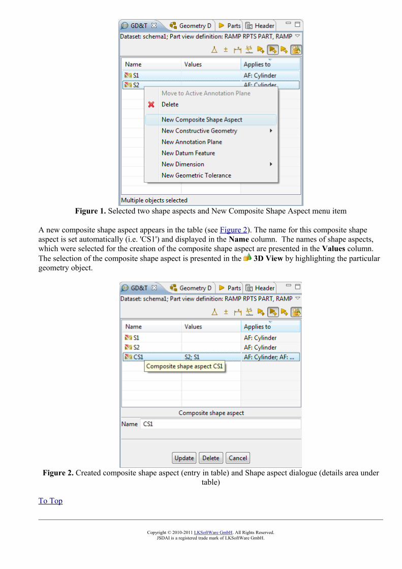
Figure 1. Selected two shape aspects and New Composite Shape Aspect menu item
A new composite shape aspect appears in the table (see Figure 2). The name for this composite shape aspect is set automatically (i.e. 'CS1') and displayed in the Name column. The names of shape aspects, which were selected for the creation of the composite shape aspect are presented in the Values column.The selection of the composite shape aspect is presented in the 3D View by highlighting the particular geometry object.
Figure 2. Created composite shape aspect (entry in table) and Shape aspect dialogue (details area under table)
To Top
Copyright © 2010-2011 LKSoftWare GmbH. All Rights Reserved.JSDAI is a registered trade mark of LKSoftWare GmbH.

9.7.2.2. Constructive GeometryIn this topic you will find a description how to create explicit construction geometry elements (point, line, plane) and derived construction geometry elements for selected shape elements in the GD&T view. Note. To view the created explicit construction geometry element, ensure that the Other features filter button is turned On, in case of derived construction geometry element, the Derived features filtering button should be turned On.When creating a new point/line/plane or a derived shape element in the GD&T view, a new constructive geometry model element is created in the Geometry Details view, under the active construction geometry model (see Figure 1).
Figure 1. Geometry details view with construction geometry model element
New point
Follow the routine to create a point using explicit entered geometric values for a construction geometry model:
• Right click on the GD&T view table area.• Select the New Constructive Geometry -> Point item in the appeared context sensitive menu. • Specify parameters for the point in the Point wizard, which appears under the table (see Figure 2):
Figure 2. Point wizard with specified parameters for construction geometry element - point
• The name for a point (C with a number) is automatically added to the Name field. This default name can be edited by entering a new text into the Name field.
• Enter x, y and z values into the Point text fields to specify coordinates of the point to be created. Note. In case some point on edge or surface was selected in the 3D View, the x, y and z values are filled automatically.
• Press the Create button to confirm choices and create a point.
The created point appears in the table of the GD&T view and under the particular construction geometry model in the Geometry Details view. In case the point element is selected in the table, the Point wizard appears under the table (see Figure 3). The point parameters can be updated by entering new values and pressing the Update button. The point can be removed by pressing Delete button. In case the

point has an association with some other elements, the Delete button is disabled.
Figure 3. Created point ('C1') in table, Point details in wizard under table
New line
Follow the routine to create a line using explicit entered geometric values for a construction geometry model:
• Right click on the GD&T view table area.• Select the New Constructive Geometry -> Line item in the appeared context sensitive menu. • Specify parameters for the line in the Line wizard, which appears under the table (see Figure 4):
Figure 4. Line wizard with specified parameters for construction geometry element - line
• The name for a line (C with a number) is automatically added to the Name field. This default name can be edited by entering a new text into the Name field.
• Specify, how the line is defined by selecting particular radio button: • Select Point and direction to define line by specifying one point and direction:
• Enter x, y and z values into the Point text fields. • Enter x, y and z values into the Direction text fields.
Or
• Select Two points to define the line by specifying two points: • Enter x, y and z values for the First point.

• Enter x, y and z values for the Second point. • Press the Create button to confirm choices and create a line.
The created line appears in the table of the GD&T view and under the particular construction geometry model in the Geometry Details view. In case the line element is selected in the table, the Line wizard appears under the table. The line parameters can be updated by entering new values and pressing the Update button. The line can be removed by pressing Delete button. In case the line has an association with some other elements, the Delete button is disabled.
New plane
Follow the routine to create a plane using explicit entered geometric values for a construction geometry model:
• Right click on the GD&T view table area. • Select the New Construction Geometry -> Plane item in the appeared context sensitive menu. • Specify parameters for the plane in the Plane wizard, which appears under the table (see Figure
5):
Figure 5. Plane wizard
• The name for a plane (C with a number) is automatically added to the Name field. This default name can be edited by entering a new text into the Name field.
• Specify, how the plane is defined by selecting particular radio button: • Select Point and normal to create plane by specifying a point on plane and two vectors:
• Enter x, y and z values for the Point. • Enter x, y and z values for the Normal direction. • Select (optionally) the Reference direction option to specify x, y and z values for
the second vector.
Or
• Select Three points radio button to create a plane by specifying three points: • Enter x, y and z values for the First point. • Enter x, y and z values for the Second point. • Enter x, y and z values for the Third point.
• Press Create button to confirm choices and create a plane.
The created plane appears in the table of the GD&T view and under the particular construction geometry model in the Geometry Details view. In case the plane element is selected in the table, the Plane wizard appears under the table. The plane parameters can be updated by entering new values and pressing the Update button. The plane can be removed by pressing Delete button. In case the plane has

an association with some other elements, the Delete button is disabled.
Create derived shape elements
Follow the routine to create a derived shape aspect in the GD&T view table:
• Ensure that Derived features and Integral features filtering buttons are turned On.• Select an applicable shape aspect in the table. Note. If no shape aspects are available in the table,
the creation of a derived shape aspect is not possible.• Right click and select New Constructive Geometry menu item in the appeared context sensitive
menu. A sub menu appears on the screen, which content depends on the shape aspect was selected previously. Select one of available sub menu entries, such as Apex, Symmetry axis, symmetry plane and etc. Note. In our example the selected shape aspect is cylinder, so the available derived shape aspect is a 'Symmetry axis'. A new derived shape aspect appears in the table (see Figure 6). The name for this derived shape aspect is set automatically (i.e. 'DS1') and displayed in the Category column. A name of a shape aspect, which was selected for the creation of the derived shape aspect is presented in the Values column.
Figure 6. Created derived shape aspect
• Select the derived shape aspect entry in the table ('DS1') to display it highlighted in the 3D View together with the associated shape aspect ('S6') (see Figure 7).

Figure 7. Selected derived shape aspect ('DS1') is highlighted (black line) in 3D View with associated shape aspect ('S6' - highlighted in red colour)
See also: Create Apex Create Symmetry Axis Create Symmetry Plane Create Symmetry Point Create Common Line Create Common Plane Create Intersection Create Offset Create Perpendicular Line Create Perpendicular Plane Create Tangent Plane
To top
Copyright © 2010-2012 LKSoftWare GmbH. All Rights Reserved.JSDAI is a registered trade mark of LKSoftWare GmbH.
9.7.2.2.1. Create Apex
Follow the routine to create an apex element in the GD&T view:
• Select a shape aspect of type cone in the table to create a cartesian point, which is an apex of the selected cone.
• Right click and select New Constructive Geometry -> Apex item in the appeared context sensitive menu (see Figure 1).

Figure 1. Selected cone shape aspect, menu item to create apex and cone geometry presentation in 3D View
The apex shape aspect with the default name DS<number>appears in the table after menu item is selected. Select the created item in the table to view details and highlight it (together with referenced shape aspects) in the 3D View (i.e. 'DS1', see Figure 2).
Figure 2. Created apex entry in GD&T table ('DS1')
To top
Copyright © 2010-2011 LKSoftWare GmbH. All Rights Reserved.JSDAI is a registered trade mark of LKSoftWare GmbH.
9.7.2.2.2. Create Symmetry Axis
Follow the routine to create a symmetry axis in the GD&T view:
• Select a shape aspect:

• cylinder - to create a line, which is a center line of the selected cylinder.• cone - to create a line, which is a center line of the selected cone.• toroid - to create a line, which is a center line of the selected toroid.• revolution - to create a line, which is a center line of the selected revolution.
• Right click and select New Constructive Geometry -> Symmetry axis item in the appeared context sensitive menu (see Figure 1).
Figure 1. Selected cylinder shape aspect, menu item to create symmetry axis and cylinder geometry presentation in 3D View
The centre axis entry with the default name DS<number> (i.e. 'DS1') appears in the table after menu item is selected. Select the created item in the table to view details and highlight it (together with referenced shape aspects) in the 3D View (i.e. 'DS1', see Figure 2).
Figure 2. Created symmetry axis in GD&T view (table and details area) and in 3D View.
To top

Copyright © 2010-2011 LKSoftWare GmbH. All Rights Reserved.JSDAI is a registered trade mark of LKSoftWare GmbH.
9.7.2.2.3. Create Symmetry Plane
Follow the routine to create a symmetry plane in the GD&T view:
• Select two shape aspects of type plane to create a plane, which is a supposed mirror for the selected planes. Each pair of points (one point on one plane, other - on the second) have the symmetrical relationship with a respect to the plane, which is called symmetry plane.
• Right click and select New Constructive Geometry -> Symmetry plane item in the appeared context sensitive menu (see Figure 1).
Figure 1. Selected items: two plane items, menu item to create symmetry axis in GD&T view and two planes in 3D View
The centre plane entry with the default name DS<number> appears in the table after menu item is selected. Select the created item in the table to view details and highlight it (together with referenced shape aspects) in the 3D View (i.e. 'DS1', see Figure 2).
Figure 2. Created symmetry plane in GD&T view (table and details area) and in 3D ViewTo top

Copyright © 2010-2011 LKSoftWare GmbH. All Rights Reserved.JSDAI is a registered trade mark of LKSoftWare GmbH.
9.7.2.2.4. Create Symmetry PointFollow the routine to create a symmetry point:
• Select a shape aspects: • circle - to create a Cartesian point, which is a center point for the selected circle.• sphere - to create a Cartesian point, which is a center point of the selected sphere.
• Right click and select New Constructive Geometry -> Symmetry point item in the appeared context sensitive menu (see Figure 1).
Figure 1. Selected items: circle item, menu item to create symmetry point in GD&T view and circle in 3D View
The centre point entry with the default name DS<number> appears in the table after menu item is selected. Select the created item in the table to view details and highlight it (together with referenced shape aspects) in the 3D View (i.e. 'DS1', see Figure 2).
Figure 2. Created symmetry point in GD&T view (table and details area) and in 3D View. To top
Copyright © 2010-2011 LKSoftWare GmbH. All Rights Reserved.JSDAI is a registered trade mark of LKSoftWare GmbH.

9.7.2.2.5. Create Common Line
Follow the routine to create a common line in the GD&T view:
• Select two shape aspects of type points (vertex point, centre point and etc.) to create a line, which goes through the selected points.
• Right click and select Create Constructive Geometry -> Common Line item in the appeared context sensitive menu (see Figure 1).
Figure 1. Selected items: two vertex point items, menu item to create common line in GD&T view and two points in 3D View
The geometric alignment entry with the default name DS<number> appears in the table after menu item is selected. Select the created item in the table to view details and highlight it (together with referenced shape aspects) in the 3D View (i.e. 'DS1', see Figure 2).
Figure 2. Created common line in GD&T view (table and details area) and in 3D View
To top

Copyright © 2010-2011 LKSoftWare GmbH. All Rights Reserved.JSDAI is a registered trade mark of LKSoftWare GmbH.
9.7.2.2.6. Create Common Plane
Follow the routine to create a common plane in the GD&T view:
• Select two shape aspects: • two lines - to create a plane, which goes through the selected lines. • line and point - to create a plane, which goes through the selected line and the specified
point. • Right click and select Create Constructive Geometry -> Common Plane item in the appeared
context sensitive menu (see Figure 1).
Figure 1. Selected items: two lines, menu item to create common plane in GD&T view and two lines in 3D View
The geometric alignment entry with the default name DS<number> appears in the table after menu item is selected. Select the created item in the table to view details and highlight it (together with referenced shape aspects) in the 3D View (i.e. 'DS1', see Figure 2).

Figure 2. Created common plane in GD&T view (table and details area) and in 3D View
To top
Copyright © 2010-2011 LKSoftWare GmbH. All Rights Reserved.JSDAI is a registered trade mark of LKSoftWare GmbH.
9.7.2.2.7. Create Intersection
Follow the routine to create an intersection of two elements in the GD&T view:
• Select two shape aspects: • two lines - to create a Cartesian point, which is an intersection of two non parallel lines. • two planes - to create a line, which is an intersection of two non parallel planes. • plane and cylinder - to create a circle, an ellipse or a line:
• in case the selected plane goes across the cylinder, an intersection is a circle or an ellipse.
• in case the selected plane goes along the cylinder, an intersection is a line (the result can be one or two lines).
• plane and line - to create a Cartesian point, which is an intersection of non parallel objects - line and plane.
• line and cylinder - to create a Cartesian point, which is an intersection of non parallel objects - line and cylinder.
• line and sphere - to create a Cartesian point, which is an intersection of line and sphere. • plane and sphere - to create a circle or a Cartesian point:
• in case the selected plane crosses the sphere, an intersection is a circle. • in case the selected plane is a tangent plane for the selected sphere, an intersection
is a Cartesian point.• Right click and select Create Constructive Geometry -> Intersection item in the appeared
context sensitive menu (see Figure 1).

Figure 1. Selected items: plane and cylinder, menu item to create intersection in GD&T view and plane and cylinder in 3D View
The intersection entry with the default name DS<number> appears in the table after menu item is selected. Select the created item in the table to view details and highlight it (together with referenced shape aspects) in the 3D View (i.e. 'DS1', see Figure 2).
Figure 2. Created imaginary intersection (Line) in GD&T view (table and details area) and in 3D View
To top
Copyright © 2010-2011 LKSoftWare GmbH. All Rights Reserved.JSDAI is a registered trade mark of LKSoftWare GmbH.
9.7.2.2.8. Create Offset
Follow the routine to create an offset in the GD&T view:

• Select a shape aspect (for example point, line or plane).• Right click and select Create Constructive Geometry -> Offset item in the appeared context
sensitive menu (see Figure 1).
Figure 1. Selected items: line, menu item to create offset in GD&T view and line in 3D View
• The Offset wizard dialogue appears in the details area of the GD&T view. Enter the offset parameters into the wizard fields (see Figure 2):
Figure 2. Offset wizard dialogue
• Name field is filled automatically with the default value for derived shapes (DS and number). You can enter or edit the name of the offset if needed.
• Enter Direction values into the x, y and z fields. • Enter the Magnitude value into the text field. • Press the Create button to confirm your selection.
The offset entry appears in the table with the default name DS<number>. Select the created item in the table to view details and highlight it (together with referenced shape aspects) in the 3D View (i.e. 'DS1', see Figure 3).

Figure 3. Created line offset in GD&T view (table and details area) and in 3D View
To top
Copyright © 2010-2011 LKSoftWare GmbH. All Rights Reserved.JSDAI is a registered trade mark of LKSoftWare GmbH.
9.7.2.2.9. Create Perpendicular Line
Follow the routine to create a perpendicular line in the GD&T view:
• Select two shape aspects: • plane and point - to create a line, which is perpendicular to the selected plane and goes
through the specified point.• sphere and point - to create a line, which is a sphere center axis through the specified
point.• cylinder ant point - to create a line, which is perpendicular to the center axis of the
selected cylinder and goes through the specified point.• cone and point - to create a line, which is perpendicular to the surface of the selected cone
at the specified point.• Right click and select Create Constructive Geometry -> Perpendicular line item in the
appeared context sensitive menu (see Figure 1).

Figure 1. Selected items: plane and point, menu item to create perpendicular line in GD&T view and surface and point in 3D View
The perpendicular entry with the default name DS<number> appears in the table after menu item is selected. Select the created item in the table to view details and highlight it (together with referenced shape aspects) in the 3D View (i.e. 'DS1', see Figure 2).
Figure 2. Created perpendicular line in GD&T view (table and details area) and in 3D View
To top
Copyright © 2010-2011 LKSoftWare GmbH. All Rights Reserved.JSDAI is a registered trade mark of LKSoftWare GmbH.

9.7.2.2.10. Create Perpendicular Plane
Follow the routine to create a perpendicular plane in the GD&T view:
• Select two shape aspects: • plane and line - to create a plane, which is perpendicular to the selected plane and goes
through the specified line. • line and point - to create a plane, which is perpendicular to the selected line and goes
through the specified point. • cylinder and point - to create a plane, which is perpendicular to the center axis of the
selected cylinder and goes through the specified point. • Right click and select Create Constructive Geometry -> Perpendicular plane item in the
appeared context sensitive menu (see Figure 1).
Figure 1. Selected items: plane and line, menu item to create perpendicular plane in GD&T view and surface and line in 3D View
The perpendicular entry with the default name DS<number> appears in the table after menu item is selected. Select the created item in the table to view details and highlight it (together with referenced shape aspects) in the 3D View (i.e. 'DS1', see Figure 2).

Figure 2. Created perpendicular plane in GD&T view (table and details area) and in 3D View
To top
Copyright © 2010-2011 LKSoftWare GmbH. All Rights Reserved.JSDAI is a registered trade mark of LKSoftWare GmbH.
9.7.2.2.11. Create Extension
Follow the routine to create an extension in the GD&T view:
• Select a shape aspect of type plane to create a plane, which is an extension of the selected plane. • Right click and select Create Constructive Geometry -> Extension item in the appeared context
sensitive menu (see Figure 1).
Figure 1. Selected items: plane, menu item to create extension in GD&T view and surface in 3D View

The extension entry with the default name DS<number> appears in the table after menu item is selected. Select the created item in the table to view details and highlight it (together with referenced shape aspects) in the 3D View (i.e. 'DS1', see Figure 2).
Figure 2. Created extension in GD&T view (table and details area) and in 3D View
To top
Copyright © 2010-2011 LKSoftWare GmbH. All Rights Reserved.JSDAI is a registered trade mark of LKSoftWare GmbH.
9.7.2.2.12. Create Tangent PlaneFollow the routine to create a tangent plane:
• Activate the 3D View. Ensure, that need selection mode buttons are switched On.• Select two shape aspects in the 3D View (ensure, if need selection mode buttons are switched
On): • cylinder and point (point on surface) - to create a plane that touches the selected cylinder
at the specified point.• cone and point (point on surface) - to create a plane that touches the selected cone surface
at the specified point. • sphere and point (point on surface) - to create a plane that touches the selected sphere at
the specified point. • Right click and select Create Constructive Geometry -> Tangent plane item in the appeared
context sensitive menu (see Figure 1).

Figure 1. Selected items: cylinder and point, menu item to create tangent plane in GD&T view and cylinder surface and point in 3D View
The tangent entry with the default name DS<number> appears in the table after menu item is selected. Select the created item in the GD&T view table to view details and highlight it in the 3D View (i.e. 'DS1', see Figure 2).
Figure 2. Created tangent plane in GD&T view (table and details area) and in 3D View
To top

Copyright © 2010-2011 LKSoftWare GmbH. All Rights Reserved.JSDAI is a registered trade mark of LKSoftWare GmbH.
9.7.3. Annotation PlaneAn Annotation Plane is a conceptual plane containing annotations.The GD&T view displays annotation planes of active Style/Annotation Model (which can be selected in the Geometry Details view) and they are filtered with a Shape Aspects filter.A user has a possibility to create, modify and delete an annotation plane, move selected annotation items to the active annotation plane.
Create annotation plane
Follow the routine to create an annotation plane in the GD&T view table:
• Select a shape aspect in the table. In our example a planar shape aspect (Plane) is selected.Note. It is not the required selection. In case no shape aspect is selected, more parameters have to be entered manually.
• Right click and select the New Annotation Plane item in the appeared context sensitive menu. • The Annotation Plane wizard dialogue appears in the details area of the GD&T view (see
Annotation Plane Wizard).
The created annotation plane entry appears in the GD&T view table (see Figure 1). The created annotation plane is marked (displayed in bold) as a currently active annotation plane.
Figure 1. Created annotation plane (highlighted entry in GD&T table) and in 3D View
Let's introduce, how the population of an annotation plane depends on the selection:
1. Selection is a single point and any number (zero as well) of faces/edges. In this case the proposed annotation plane is one going through that point with normal (0, 0, 1). In other words Point is set to the selected point, Normal direction is set to (0, 0, 1) and Orientation is set to zero.
2. Selection is three different points not on the same line and any number (zero as well) of faces/edges. In this case the proposed annotation plane goes through all the selected points with

normal being a cross product between two vectors: the first point to the second point, the first point to the third point. In other words Point is set to the first selected point. Normal direction is set to a cross product between two vectors: the first point to the second point, the first point to the third point. Orientation is set to an angle between two vectors: the first point to the second point, the first point to the third point. You could also say that orientation is along a vector from the first point to the second point.
3. Selection is a single advanced face with a plane as an underlying geometry. In this case tan annotation plane will be the same as the selected plane and with the same normal as the selected advanced face.
4. Selection is a single plane. In this case an annotation plane will be the same as the selected plane.
Annotation Plane Wizard
In this topic, you will find a description of the Annotation Plane wizard content (see Figure 2) and how to enter parameters:
Figure 2. Annotation Plane wizard dialogue in GD&T view
• The Name field presents a default name of the annotation plane to be created (i.e., 'AP1', 'AP2' and etc.). Planes, that are used for annotations have unique names within all the Style/Annotation and Geometric Models of one design ( Geometry Details view).To change a default value - enter a new or edit the currently entered name.Note. If a manually entered name already exist in the currently active Style/Annotation Model, the error message appears at the bottom section of the wizard dialogue.
• Select one of the radio buttons to define, how the annotation plane should be defined: • Point and normal, or• Three points.
• In case the Point and normal radio is selected: • Enter coordinates of a Point into x, y and z field. • Enter coordinates of a Normal direction into x, y and z fields.• Enter a value of the annotation plane orientation angle (degrees) into the Orientation field.
The Orientation of the annotation plane defines an orientation of the text of annotation items, associated to this annotation plane. The annotation text reading direction is according X coordinate axis.To apply the changed orientation for annotation item, you have to update each annotation item (i.e. select annotation item in the GD&T view table and press the Update button in the annotation item wizard, which appears in the details area).Note. If a planar surface is selected, then the Point, Normal direction coordinates and Orientation angle value are added automatically.
• In case the Three points radio is selected: • Enter coordinates of a First point into the x, y and z fields. • Enter coordinates of a Second point into the x, y and z fields. • Enter coordinates of a Third point into the x, y and z fields.

Note. If a planar surface is selected, then the First, Second and Third point coordinates are added automatically.
• Press the Create button to create an annotation plane.
Update annotation plane data
To update parameters of an annotation plane:
• Select an annotation plane entry in the GD&T view table. The Annotation Plane wizard dialogue appears under the table in the details area (see Figure 3).
• Update needed annotation plane data: • Edit or enter a new annotation name into the Name field. • Edit or enter a new value of the annotation plane orientation angle (degrees) into the
Orientation field. • The Normal direction fields are disabled for editing. To flip the direction of the
annotation plane, press the Flip button.• Press the Update button to confirm changes.
Figure 3. Annotation plane wizard dialogue to update annotation plane with pressed Flip button
Remove annotation plane
To remove an annotation plane:
• Press Delete button in the Annotation Plane wizard page.
Or
• Select an applicable annotation plane entry in the GD&T view table. • Right click and select the Delete item in the appeared context sensitive menu.
Note. In the case that there are annotations or callous on the annotation plane the user is asked on whether or not proceed with deletion
If some annotation item was situated on the recently removed annotation plane, the warning icon is added to the particular annotation item entry icon (see Figure 4). Fly over the icon with a mouse to see the warning text.

Figure 4. Dimension icon with the warning icon and tool tip with the warning text.
Active annotation plane
The currently active annotation plane entry is displayed by using bold text font in the GD&T view table. To change the active annotation plane:
• Select an applicable annotation plane entry in the GD&T view table. • Right click and select Activate item in the appeared context sensitive menu.
Move to active annotation plane
Annotation items, presented in the GD&T view table can be associated to various annotation planes. There is a possibility to move the annotation item to the active annotation plane:
• Select the annotation item in the GD&T view table. • Right click and select the Move to active annotation plane item in the appeared context sensitive
menu.
To top
Copyright © 2010-2011 LKSoftWare GmbH. All Rights Reserved.JSDAI is a registered trade mark of LKSoftWare GmbH.
9.7.4. Datum FeatureA Datum feature is the actual surface component to establish a datum (points, lines, surfaces, planes and etc., from which a location or geometric relationships of other features may be established or related).
Create datum feature
Follow the routine to create a datum feature entry in the GD&T view table for selected shape aspect (for example plane):
• Right click and select New Datum Feature item in the appeared context sensitive menu (see Figure 1).
• The Create Datum Feature wizard dialogue appears in the GD&T view details area. How to manipulate with the wizard, see Create Datum Feature Wizard.

Figure 1. Shape aspect S1 in GD&T table to be defined as a datum feature A (wizard dialogue) and highlighted surface in 3D View
A new entry of datum feature appears in the GD&T view table (see Figure 2):
• the identification of a datum feature is presented in the Name column, • the shape aspect the datum feature was made from (i.e. S1) is displayed in the Values column, • the geometry element the created shape aspect is applied to (i.e. plane) is defined in the Applies to
column.
Fly over the datum feature icon to view a tool tip, which contains additional information:
• The text Datum feature with the datum feature identification value, and • The annotation plane the created datum feature is currently associated to.
Note. A new annotation plane (i.e. AP1) is created together with a new datum feature (i.e. A), in case no annotation plane were previously created.

Figure 2. Created datum feature A in GD&T view (instead of shape aspect S1) and in 3D view (datum feature symbol)
Create Datum Feature Wizard
The Create Datum Feature wizard helps to create a datum feature for selected element (see Figure 3):
• The default identification label is automatically added into the Identification text field. To change the value - enter a new text, identifying the datum feature.In our example we have selected shape aspect S1 (in the GD&T view table), which will be defined as a datum feature with the identification A.
• Feature of size check box. Select this check box if the datum feature is a feature of size. Note. The Feature of size check box is enabled for selection only if the symmetry element can be created for the selected geometric feature (i.e. for cylinder, cone, circle, two planes and etc.). In case there are selected a few geometric features and each of them are symmetrical, the dialogue still allows user to set a Feature of size flag.
• Press the Create button to create a new datum feature.
Figure 3. Create Datum Feature wizard page
Update datum feature
To update a datum feature:
• Select a datum feature entry in the GD&T view table. The Datum Feature wizard dialogue appears in the details area.
• Enter a new identifier into the Identification text field.

• The Feature of size check box is enabled for edition only if the selected feature can be a feature of size.
• Press the Update button to confirm your changes.
Delete datum feature
To remove a datum feature:
• Select the datum feature element in the GD&T view table. • Press Delete button in the GD&T view details area.
Or
• Right click on the datum feature entry in the GD&T view table. • Select Delete menu item in the appeared context sensitive menu.
To top
Copyright © 2010-2011 LKSoftWare GmbH. All Rights Reserved.JSDAI is a registered trade mark of LKSoftWare GmbH.
9.7.5. Datum TargetA Datum Target is a specified point, line or area on a part that is used in establishing a datum.
The datum targets are displayed in the table list of the GD&T view if the filer button Datums is switched On (see Figure 1):
• Name column displays datum feature identification and number of the datum target. Fly by with a mouse over the Name cell to view a content of the tool tip, which contains an additional information about the selected datum target:
• Full name of the table element - datum target, type of the target (in parenthesis) and a name of the target.
• Annotation plane identification, which the selected target is associated to.• Values column - value of a particular datum target (empty cell for Target Point, line length for
Target Straight Line, diameter for Target Circle and Circular Curve and width x length for Target Rectangle).
• Applies to column - the datum identification, to which the target applies.

Figure 1. List of datum targets with tool tip displaying additional information about the datum target entry and datum target annotations in 3D View
Create Datum Target Wizards
In case some datum target creation was performed in the 3D View, the particular datum target creation wizard is prompted in the GD&T view details area. The following wizards may appear:
• Create Target Point , • Create Target Straight Line , • Create Target Circle , • Create Target Circular Curve , • Create Target Rectangle .
For more information, how the created datum targets are presented on a geometry model in the 3D View, see Datum Target.
Create Target Point Wizard
The Create Target Point wizard dialogue is displayed in case the Datum Target -> Point Datum Target menu item is selected in the 3D View (see Figure 2):
Figure 2. Create Target Point wizard dialogue

• The Datum field presents a default value for the datum the target point is associated to. To change a default value - enter a new datum identifier or select from the drop down list.
• The Target Number field present a default value of the target number. To change this value - enter a new number into the text field.
• The Coordinates x, y, z fields presents default coordinates of the selected point on the 3D View geometry model. The precision for values, displayed in the field can be managed by changing decimal places value in the GD&T preferences (see Preferences -> GD&T). To change the default coordinate values - enter new coordinates into x, y, z fields.
• Press the Create button to create a datum target point.
The created target point appears in the table list of the GD&T (see Figure 1).
Create Target Straight Line Wizard
The Create Target Straight line wizard dialogue is displayed in case the Datum Target -> Line Datum Target menu item is selected (see Figure 3):
Figure 3. Create Target Straight Line wizard
• The Datum field presents a default value for the datum the target straight line is associated to. To change a default value - enter a new datum identifier or select from the drop down list.
• The Target Number field present a default value of the target number. To change this value - enter a new number into the text field.
• The Coordinates x, y, z fields presents default coordinates of the selected point (the start point of a target straight line) on the 3D View geometry model. The precision for values, displayed in the field can be managed by changing decimal places value in the GD&T preferences (see Preferences -> GD&T). To change the default coordinate values - enter new coordinates into x, y, z fields.
• Enter the value of an angel (degrees) into the Orientation field. • Enter the line length value into the Length field.• Press the Create button to create a datum target straight line.
The created target straight line appears in the table list of the GD&T view (see Figure 1).
Create Target Circle Wizard
The Create Target Circle wizard dialogue is displayed in case the Datum Target -> Circle Datum Target menu item is selected (see Figure 4):

Figure 4. Create Target Circle wizard
• The Datum field presents a default value for the datum the target circle is associated to. To change a default value - enter a new datum identifier or select from the drop down list.
• The Target Number field present a default value of the target number. To change this value - enter a new number into the text field.
• The Coordinates x, y, z fields presents default coordinates of the selected point (the center point of a target circle) on the 3D View geometry model. The precision for values, displayed in the field can be managed by changing decimal places value in the GD&T preferences (see Preferences -> GD&T). To change the default coordinate values - enter new coordinates into x, y, z fields.
• Enter the target circle diameter value into the Diameter text field.• Press the Create button to create a datum target circle.
The created target circle appears in the table list of the GD&T view (see Figure 1).
Create Target Circular Curve Wizard
The Create Target Circular Curve wizard dialogue is displayed in case the Datum Target -> Circular Curve Datum Target menu item is selected. The wizard dialogue is identical to the Create Target Circle wizard dialogue. The difference between created datum target is, that the Target Circle is the circle area and the Target Circular Curve - only the curve of a circle.
Create Target Rectangle Wizard
The Create Target Rectangle wizard dialogue is displayed in case the Datum Target -> Rectangle Datum Target menu item is selected (see Figure 5):
Figure 5. Create Target Rectangle wizard

• The Datum field presents a default value for the datum the target rectangle is associated to. To change a default value - enter a new datum identifier or select from the drop down list.
• The Target Number field present a default value of the target number. To change this value - enter a new number into the text field.
• The Coordinates x, y, z fields presents default coordinates of the selected point on the 3D View geometry model. The precision for values, displayed in the field can be managed by changing decimal places value in the GD&T preferences (see Preferences -> GD&T). To change the default coordinate values - enter new coordinates into x, y, z fields.
• Enter the value of an angel (degrees) into the Orientation field. • Enter the rectangle length value into the Length field. • Enter the rectangle width value into the Width field. • Press the Create button to create a datum target rectangle. The created target rectangle appears
in the table list of the GD&T (see Figure 1).
Update datum target
To update parameters of a datum target:
• Select an applicable datum target entry in the GD&T view table. The particular wizard dialogue appears under the table in the details area.
• Update needed datum target data (see Create Datum Target Wizards for details) and press the Update button.
Remove datum target
To delete an incorrect or redundant datum target:
• Select a datum target in the GD&T view table. • Press delete button in the GD&T view details area.
Or
• Right click and select Delete menu item in the appeared context sensitive menu.
To top
Copyright © 2010-2012 LKSoftWare GmbH. All Rights Reserved.JSDAI is a registered trade mark of LKSoftWare GmbH.
9.7.6. Datum SystemA Datum system is a group of two or more separate datums used as a combined reference for a toleranced feature. Note. A datum system in IDA-STEP may be comprised of a single datum.
How to start creation of a datum system, see Clause Create datum system.After the creation, a new entry of the datum system appears in the GD&T view table (see Figure 1):

Figure 1. Created datum system (DRF1) in table and Datum System parameters in details area
• the identification of a datum system is presented in the Name column (i.e. 'DRF1'), • the datum feature or set of datum features with applied modifiers (i.e. A |B - C), which areⓂ Ⓛ
included in the created datum system, is displayed in the Values column.
Fly over the datum system icon to view a tool tip, which contains additional information (Datum system with the datum system identification value). If a datum system entry is selected in the GD&T view table, the Datum System window with the datum system parameters is presented in the details area.
Create Datum System Wizard
The Create Datum System wizard guides in the creation of a new datum system (see Figure 2):
a) b)

Figure 2. Create Datum System wizard page: a) datums not specified b) with specified datums
• The default identification label of the datum system to be created (i.e. 'DRF1') is automatically added into the Name text field. To change the value - enter a new text, identifying the datum system.
• Specify constituents of the datum system by selecting datum features in the Primary, Secondary and/or Tertiary combo boxes:
• Initially you can see only one combo box next to the Primary, Secondary and Tertiary labels (see Figure 2 a). After the value is selected in the first combo box, another one appears next the first one (see Figure 2 b). You can specify datums as many as needed in each constituent line.
• You can specify a modifier for each datum feature by pressing on the small square next to the datum feature combo box. The Modifiers dialogue window appears on the screen (see Figure 3). The dialogue window contains two sections Modifiers supported by ISO and Modifiers not supported by ISO. You can collapse or expand those sections by using double arrows next to the section label or just by clicking on the label. To select an applicable modifiers, set a check mark in front of a needed modifier. Note. In some cases, i.e. Modifiers not supported by ISO, Distance modifier, additionally the number value should be specified in the text field. Press OK button to confirm selections and close the window. Selected modifiers appear next to the particular datum feature field.

Figure 3. Modifiers dialogue window
• The Coordinate system values are entered automatically as soon as constituents of a datum system are selected. To change the coordinate system parameters:
• Enter new location x, y and z values into particular fields next to the Location label. • Enter new orientation values into α, β and γ fields next to the Orientation label.
• Press Create button to create a datum system with specified parameters.
Update datum system
To update a datum feature:
• Select a datum system entry in the GD&T view table. The Datum System dialogue appears in

the details area (see Figure 1).• Enter a new parameters for a datum system (see Create Datum System Wizard for details). • Press Update button to confirm your changes.
Delete datum system
To remove a datum system:
• Select the datum system element in the GD&T view table. • Press Delete button in the GD&T view details area.
Or
• Right click on the datum system entry in the GD&T view table. • Select Delete menu item in the appeared context sensitive menu.
Note. If the selected datum system is used by any GD&T element, the delete action is not available (Delete button and Delete menu item are disabled).
To top
Copyright © 2011 LKSoftWare GmbH. All Rights Reserved.JSDAI is a registered trade mark of LKSoftWare GmbH.
9.7.7. Dimensions
IDA-STEP presents a possibility to define dimensions of selected shape aspects in the GD&T view:
• Size dimension - a specified value of a diameter (spherical diameter), radius, length directly related to the size of an object;
• Distance dimension - measure the distance between two points, measured in the default units;• Angular dimensions - measure the angle between two lines, planes, cones, surfaces sharing a
common end point called the vertex.
Create Dimension
To create a particular dimension (for example for a shape aspect of type Circle):
• Select a shape aspect of type Cylinder in the GD&T view table or a particular geometry element in the 3D View geometry model. Note. In some cases, two shape aspects can be selected for creating a dimension (to measure a distance between two shape aspects)
• Right click and select New Dimension -> Angular/Distance/Size menu item in the appeared context sensitive menu (see Figure 1). Note. In case some dimensioning for the selected shape aspect is not available, the particular sub menu item is disabled.

Figure 1. Selected shape aspect of type Circle, context sensitive menu New Dimension -> Angular/Distance/Size
After the menu item (Angular, Distance, or Size) is selected, the particular wizard dialogue, named according the selected dimension type, appears under the table (see Angular/Distance/Size Dimension Wizard). In our example only Size dimension is available for the selected shape aspect Cylinder.
The created dimension object appears in the table. The name of shape aspect, for which the dimension is created is defined in the Applies to column. In our example the created dimension is size dimension, cylinder diameter with plus minus toleranced value, applies to S1 shape aspect (see Figure 2).In case the dimension object is selected, the wizard is displayed under the table, where the value and other parameters can be updated for the selected dimension by pressing the Update button.
Figure 2. Created size dimension is highlighted in GD&T view table and presented in 3D View (highlighted together with the related cylinder surface)

Note. To view the list of available shape aspects and dimensions, the Shape aspects and Dimensions filter buttons must be switched On (above the table).
Angular/Distance/Size Dimension Wizard
The Angular/Distance/Size Dimension Wizard guides a user, how to create a particular dimension for the selected shape aspect:
a) b)
c) Figure 3. a) Angular Dimension wizard, b) Distance Dimension wizard, c) Size Dimension wizard
• Name text field presents a name of the dimension, which appears in the Name table column after the dimension is created. By default the name is entered automatically D<number>. The default value can be edited or a new text can be added to the Name field.
• Type list presents the types of size dimension, available for the selected shape aspect. For example, in case the Circle shape aspect is created, the Type list contains three predefined values: diameter (to measure diameter of the selected circle), radius (to measure radius of the selected circle) and length (to measure arc length of the selected circle). In case of the Sphere, the Type list contains predefined values: Spherical diameter and Radius. In other cases only one type value may appear in the list. Note. In case distance dimension or the angular dimension, the selection of dimension type is not available as the Type combo box does not appear at all (see Figure 3 a and b). Select an applicable value from the list to define the type of dimension. Note. In our example the Diameter type is selected (Size Dimension wizard dialogue).
• Value indicates the amount a measured distance can vary (dimension with tolerances). Note. Value should not be negative (there are some exceptions for angular dimension). The error message appears in the wizard window bottom section, informing about wrong value. Select the type of the value in the drop down list. Available predefined values are:
• Select Limit to set limits of the dimension value (see Figure 4):

• Enter the lowest value into the Low text field. Note. In case of an angular dimension, the Low value must not be less than -90 degrees.
• Enter the highest value into the High text field. Note. In case of an angular dimension, the High value must not be more than 450 degrees.
Note. In case the dimension in one direction only (only Low or High value is specified for the dimension), the created dimension value is followed by text string min./max. in the GD&T view table 3D View (for example '24 min.' or '24.01 max.' ).
Figure 4. Size Dimension wizard page with selected Limit value in Value drop down list
• Select ± (plus minus) to set the exact value and then the bounds of the dimension (see Figure 5):
• Enter the exact value into the Value text field. • Enter the plus value into the + text field. • Enter the minus value into the - text field.
Figure 5. Size Dimension wizard with selected ± value in the Value drop down list
• Select Class to set the exact value and tolerance class (defined in ISO 286) for the dimension (see Figure 6):
Figure 6. Size dimension wizard with selected Class value in the Value drop down list
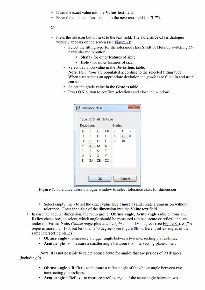
• Enter the exact value into the Value text field. • Enter the tolerance class code into the next text field (i.e "K7").
Or
• Press the icon button next to the text field. The Tolerance Class dialogue window appears on the screen (see Figure 7):
• Select the fitting type for the tolerance class Shaft or Hole by switching On particular radio button:
• Shaft - for outer features of size; • Hole - for inner features of size.
• Select deviation value in the Deviations table. Note. Deviations are populated according to the selected fitting type.When user selects an appropriate deviation the grades are filled in and user can select it.
• Select the grade value in the Grades table. • Press OK button to confirm selections and close the window.
Figure 7. Tolerance Class dialogue window to select tolerance class for dimension
• Select empty line - to set the exact value (see Figure 3) and create a dimension without tolerance . Enter the value of the dimension into the Value text field.
• In case the angular dimension, the radio group (Obtuse angle, Acute angle radio buttons and Reflex check box) to select, which angle should be measured (obtuse, acute or reflex) appears under the Value. Note. Obtuse angle plus Acute angle equals 180 degrees (see Figure 8a). Reflex angle is more than 180, but less than 360 degrees (see Figure 8b - different reflex angles of the same intersecting planes).
• Obtuse angle - to measure a bigger angle between two intersecting planes/lines;• Acute angle - to measure a smaller angle between two intersecting planes/lines;
Note. It is not possible to select obtuse/acute for angles that are periods of 90 degrees (including 0).
• Obtuse angle + Reflex - to measure a reflex angle of the obtuse angle between two intersecting planes/lines;
• Acute angle + Reflex - to measure a reflex angle of the acute angle between two

intersecting planes/lines.
Note. It is not possible to select reflex for angles that are periods of 180 degrees (including 0).
Note. In case the conical face, the Angular Dimension wizard does not contain the above radio group.
a) b)
Figure 8. a) Acute ('60 °') and obtuse ('120 °') angle for same intersecting planes; b) obtuse + reflex ('240
°') and acute + reflex ('300 °') for same intersecting planes
• Directed option appears only in case two shape aspects are selected. Select this option to emphasize that the distance must be measured exactly from the first selected shape aspect to the second one.
• TED (theoretically exact dimensions) option. In ASME they are called basic. For the presentation it is drawn a box around the value. TED is theoretically exact and it can not have a tolerance.Select this option to define the dimension is theoretically exact dimensions.
• Select the Auxiliary (optional) option to define the dimension is auxiliary. • Radio buttons group (select one of the radio buttons):
• Envelope - for ASME the Envelope requirement is default. In ISO it is indicated by .Ⓔ• Independency - this is a default in ISO. In ASME it is indicated by .Ⓘ
• After all required data are entered, press the Create button. Note. If some required data are not specified, the error message is displayed in the wizard page and the Create button is disabled until the mandatory data are entered.
When creating another dimension, the previous choice is pre-set for the following parameters:
• size type (radius, diameter etc.); • value type (+/-, limit etc.);

• directed flag; • TED flag; • auxiliary flag; • envelope flag.
Note. If some remembered value does not apply to a new dimension (e.g. a size type to a distance dimension), then it is simply ignored.
See 3D Viewer > Management of GD&T Elements -> Dimensions for dimension presentation in 3D View.
Update Dimension
To update a dimension:
• Select a dimension entry in the GD&T view table. The Angular/Size Dimension wizard dialogue appears in the details area.
• Enter new or edit parameters for the selected dimension. • Press the Update button to confirm your changes.
Note. If the selected dimension is not supported by IDA-STEP, it is only possible to change a Name of such dimension.
Delete Dimension
To remove a dimension:
• Select the dimension element in the GD&T view table. • Press Delete button in the GD&T view details area.
Or
• Right click on the dimension entry in the GD&T view table. • Select Delete menu item in the appeared context sensitive menu.
To top
Copyright © 2010-2011 LKSoftWare GmbH. All Rights Reserved.JSDAI is a registered trade mark of LKSoftWare GmbH.
9.7.8. Geometric TolerancesGeometric tolerances show acceptable variations (maximum and minimum limits) of size, form, profile, orientation, location, and runout of a feature.
In the GD&T view geometric tolerances are displayed in the table list, when the Tolerances filter button is switched On (see Figure 1):
• Name column contains a symbol that represents the geometric characteristic (type of tolerance) to which a tolerance is being applied (in our example there are flatness and position tolerance symbols). Fly over the Name cell to view the content of the tool tip:
• Type of the geometric tolerance with a name,

• Annotation plane, the selected geometric tolerance is currently associated to.• Values column contains information of the tolerance, for example diameter symbol, tolerance
value, material conditions of the tolerance, projection with value, datum reference, material conditions of datums and etc.
• Applies to column contains the shape aspect, to which the tolerance is applied.
Figure1. GD&T view table with filtered list of tolerances and 3D view with tolerance annotation
Create new geometric tolerance
To create a new geometric tolerance:
• Select a shape aspect in the GD&T view table. Note. To view the list of shape aspects - turn on the Shape aspects button.
• Right click and select New Geometric Tolerance item in the appeared context sensitive menu. • The Create Geometric Tolerance wizard appears under the table (see Figure 2). How to fill the
wizard page with data, see Create Geometric Tolerance Wizard.
The created geometric tolerance entry appears in the GD&T view table (see an example in Figure 1).
Create Geometric Tolerance Wizard
The Create Geometric Tolerance wizard (see Figure 2) helps to create a geometric tolerance for selected shape aspect/surface component:

Figure 2. Create Geometric Tolerance wizard with specified parameters
• Enter a text, by which a geometric tolerance is known, into the Name text field. Note. By default this field is filled automatically with the text 'GT<number>'. You can edit or enter a new name of the geometric tolerance to be created.
• In the Characteristic drop down list select the type of geometric tolerance to be created (see Figure 3). Note. In case an incorrect or not available type of tolerance is selected, the error message appears in the bottom section of the wizard.
Figure 3. List of geometric tolerance characteristics
• In the Applied to drop down list select the element to which the tolerance to be applied. Note. IDA-STEP suggests an element according the selected shape aspect (for example, if the selected shape aspect is of type plane, the Applied to field will be filled with value Selection). Available predefined values are:
• Selection - currently selected shape aspect;• Individual Median Feature(s) - if multiple features are selected, use median features
from each selected geometry individually;

• Single Median Feature - the median feature to construct is between two selected geometrical features (e.g. two parallel planes, two concentric cylinders or in general two equidistant surfaces, or two equidistant curves or a wedge);
• All around - all surfaces connected end-to-end 360 degrees around the part; • All over - surfaces all over the part.
• The Tolerance Value line is split up into three parts: • Combo box - select a type of the tolerance zone:
• none - the tolerance value used for linear dimensions; • ø - the tolerance zone is circular or cylindrical; • Sø- the tolerance zone is spherical.
• Text filed - enter the tolerance value. This parameter is mandatory. If no value is entered, the error message appears on the bottom section of the wizard (i.e., 'Tolerance value is not specified').
• Button next to the text field - select modifier (boundaries of a perfect form). Press the button. The Modifiers dialogue window appears on the screen (see Figure 4). The dialogue window contains two sections Modifiers supported by ISO and Modifiers not supported by ISO. You can collapse or expand those sections by using double arrows next to the section label or just by clicking on the label. To select an applicable modifiers, set a check mark in front of a needed modifier. Note. In some cases, i.e. Modifiers supported by ISO, Unequally disposed modifier, additionally the value should be specified in the text field. The Unequally disposed modifier can be applied to the profile tolerance (both - surface and line) only.Press OK button to confirm selections and close the window. Selected modifiers appear next to the tolerance value field.
Figure 4. Modifiers dialogue window with selected Maximum material requirement modifier

• The Qualifying note text field is the place to enter additional text for a geometric tolerance. Enter an applicable text into the text field. This text appears in the geometric tolerance annotation below the datum reference frame (in 3D View, see Figure 5). In case the composite geometric tolerance is created, the entered text appears on the right side of the particular tolerance.
Figure 5. Geometric tolerance annotation with qualification note ('8 holes')
• The Projection option is to define a projection tolerance zone. The projection option is enabled for positional, angularity, parallelism, perpendicularity, concentricity and symmetry tolerances.
• Select the Projection check mark. • Enter the projection value into the text field. • Select the projection end feature in the combo box drop down list.
• The Affected Plane option - select this option to define the plane to apply the tolerance value. Press the arrow button next to the text field and select a particular plane in the drop down list.
• The Unit size option - select this option to specify the size of a segment. Select an area of the segment in the combo box drop down list. Available values:
• length - in case of the length area, enter a number, which represents a length of the unit.• circular - in case the circular area, enter diameter value into the number field. A round unit
basis area is defined by a diameter symbol followed by the diameter value in the GD&T view table and in the 3D View.
• square - in case the square area, enter a length of the side of the square into the number field. A square unit basis area is defined by a square symbol followed by the length of the square side value (see an example in Figure 6).
• rectangular - in case the rectangular area, enter length and width values into the number fields next to the combo box.

Figure 6. GD&T view (left): created geometric tolerance with defined square unit area; 3D View (right): presentation
• The Datum system layout - select the datum system for a geometric tolerance in the combo box drop down list. Note. The datum system must exist in data or be previously created (how to create datum system refer to clause Create datum system).
• The Composite layout - select this option to create a combination of several tolerance frames. This option is available for line and surface profile, position tolerances. Define tolerance parameters for each line of tolerance frames (tolerance zone, value and material condition symbol).
• Press the Create button to confirm selection and create a geometric tolerance.
See also 3D View -> Management of GD&T Elements -> Geometric Tolerances (in case 3D View is available).
To top
Copyright © 2010-2011 LKSoftWare GmbH. All Rights Reserved.JSDAI is a registered trade mark of LKSoftWare GmbH.
9.7.9. Text AnnotationA Text Annotation in IDA- STEP is a 3D annotation with a free text (one or several lines).A user has a possibility to create, modify, delete a text annotation in the GD&T view. The created text annotation is presented in the 3D View (see Figure 1).

Figure 1. Text annotation in GD&T view and in 3D View
Create text annotation
Follow the routine to create a text annotation in the GD&T view table:
• Select a shape aspect in the table. In our example a Line is selected. • Right click and select the New Text Annotation item in the appeared context sensitive menu.• The Create Text Annotation wizard dialogue appears in the details area of the GD&T view.
Note. The same result can be achieved by pressing the Create Text Annotation button in the main tool bar or selecting in the main manu bar GDT -> Create Text Annotation. How to manipulate with the wizard refer to clause Create Text Annotation Wizard.
The created text annotation entry appears in the GD&T view table (see Figure 1):
• the identification of a text annotation is presented in the Name column, • the shape aspect the text annotation is applied to (i.e. S1) is displayed in the Values column, • the geometry element the created shape aspect is applied to (i.e. Line) is defined in the Applies to
column.
Fly over the text annotation icon to view a tool tip, which contains additional information:
• The text Text Annotation with the text annotation identification value, and • The annotation plane the created text annotation is currently associated to.
Note. A new annotation plane (i.e. AP1) is created together with a new text annotation (i.e. A1), in case no annotation plane were previously created.
Create Text Annotation Wizard
The Create Datum Feature wizard helps to create a datum feature for selected element (see Figure 2):

Figure 2. Create Text Annotation wizard page
• The default identification label is automatically added in the Name text field (in our example 'A1'). To change the value - enter a new text, identifying the text annotation.
• Enter a text (one or several lines) for the text annotation into the Text field. • Choose if the text annotation should apply to a selected geometric feature or to the entire shape by
selecting a particular radio button in the Apply to radio group: • Select the Feature radio button to apply a text annotation to the selected geometric feature,
or• Select the Entire shape radio button to apply a text annotation to the whole entire shape.
• Press the Create button to create a new text annotation.
Update text annotation
To update a text annotation parameters:
• Select a text annotation entry in the GD&T view table. The Text Annotation wizard dialogue appears in the details area.
• Change parameters for the selected annotation in the wizard. How to do this, refer to clause Create Text Annotation Wizard.
• Press the Update button to confirm your changes.
Delete text annotation
To remove a text annotation:
• Select an applicable text annotation entry in the GD&T view table. • Press Delete button in the GD&T view details area.
Or
• Right click on a text annotation entry in the GD&T view table. • Select Delete menu item in the appeared context sensitive menu.
To top
Copyright © 2011-2012 LKSoftWare GmbH. All Rights Reserved.JSDAI is a registered trade mark of LKSoftWare GmbH.
9.8.1. Geometry Details View
The Geometry Details view presents a hierarchy of construction geometry models, shape

representations, related to a particular part version, and style/annotation models with associated objects, such as annotation planes and occurrences (see Figure 1).The content of the Geometry Details view depends on the selection in the Parts view (selected part version). If no part version is selected in the Parts view, the Geometry Details view shows an empty page with a message "There is no selected part".
Figure 1. Geometry Details view
The Geometry Details view space is occupied by a tree table:
• Construction Geometry models - hierarchy of supplementary geometry models and their details plus styling. The node types in a standard view:
• Constructive geometry representation, • Placement, • Curve/Edge, • Surface/Face, • Vertex, • Point.
• Geometric Models - hierarchy of geometry models of the selected part/version/view with details and styling. The node types in a standard view:
• Shape, • Shape relationship, • Solid, • Shell, • Face, • Edge, • Vertex.
• Style/Annotation Models - hierarchy of style/annotation models with their annotation planes with associated annotation occurrences objects (see Styling Models for details). The node types in

a standard view: • Style Model, • Annotation Model, • Style + Annotation Model, • Not styled or annotated model, • Annotation planes, • Annotation occurrences.
• Presentation Models - presentation areas and views.
Data representation for all non-static entries in the first column of the Geometry Details view is organized in the following way:
• an icon, in front of each node is specific to the type and role of the object, • name of representation or representation item (if the name is an empty string, it is displayed just
the separator), • separator "," and• hash-number, e.g. "#1234".
Note. Look to the fly by text to learn more details about each non static node.
The default column perspective contains the following columns (full name of the column is presenetd in tool tips):
• Show/Hide - the check box to specify whether a particular object is visible or not in the 3D view (see Editing Visibility for more details);
• Surface Color - a color for a surface (see Editing Color for more details). The 'square color' indicates explicitly set color, the 'round color' - inherited color.
• Curve Color - a color for an edge (see Editing Color for more details). The 'square color' indicates explicitly set color, the 'round color' - inherited color.Note. The Geometry Details view does not display "default" styling information. All cells that use the actual system defaults are empty.
• Transparency - transparency for a surface (see Editing Transparency for more details);• Transformation - the transformation data of the shape representation object (see Editing
Transformation Data for more details). If the selected element contains transformation data, the T letter symbol appears in the column cell. Detailed transformation data are presented in the fly by text.
Note. The Geometric Details view does not display any default styling information, which can be found in Preferences -> 3D View -> Display Styles page.
To top
Tool Bar
The Geometry Details view contains it's own tool bar, where a preferable view of the geometry details hierarchy can be switched On/Off.
Button Icon Description

Show standard view
Show along STEP data structures
Show Face objects

Show Edge objects
Show Vertice objects
Show geometry with shared context
Link with Views
When this option is turned On, the Geometry Details view is linked with the 3D View and Part Details view. Any selection in one of the views is reflected in the other views.
To top
Copyright © 2009-2010 LKSoftWare GmbH. All Rights Reserved.DJSDAI is a registered trade mark of LKSoftWare GmbH.
9.8.2. Selection
The selection of some geometry element in the Geometry Details view initiates the highlighting of corresponding geometry objects in the 3D View and related shape aspects in the Parts Details view (see Figure 1).

Figure 1. Selection in Geometry Details view initiates highlighting of related objects in 3D View and Part Details view
Note. You can use buttons in the tool bar of the Geometry Details view to switch an applicable view of the geometry details hierarchy. This enable you to select various geometry elements, which are not displayed in the standard view.
To top
Copyright © 2009 LKSoftWare GmbH. All Rights Reserved.DJSDAI is a registered trade mark of LKSoftWare GmbH.
9.8.3. Construction Geometry ModelsThe construction geometry models with elements (lines, planes) are listed under the static node Construction Geometry Models in the Geometry Details view (see Figure 1):
• Root node - construction geometry models; • Child node - simple construction geometry element (line, plane, point).

Figure 1. Geometry Details View, Construction Geometry Models hierarchy
Create new model
Follow the routine to create a new construction geometry model:
• Right click on the Construction Geometry Models static node. • Select Create model menu item in the appeared context sensitive menu.
A new node appears under the Construction Geometry Models static node, named 'New model' (see Figure 2).
Figure 2. Created 'New model' node under Construction Geometry Models static node
How to create lines and planes for a construction geometry model, see Create line, Create plane.
Rename construction geometry model
The initial name of the selected construction geometry model can be changed by:
• Select the construction geometry node (for example 'New model'). • Double click or pres F2 key to enter the cell. • Enter an applicable text, which represents the model.
The entered name appears instead of the previous one under the Construction Geometry Models static node and is updated in the 3D View icon drop down list.
Create annotation plane
It is possible to to create an annotation plane from a plane that is available in Construction Geometry Models:
• Right click on a plane under the Construction Geometry Models branch. • Select Create annotation plane menu item in the appeared context sensitive menu.

In case no style/annotation model is active, a new annotation model is created under the Style/Annotation Models branch, otherwise the active sty;e/annotation model is supplemented with a new annotation plane.
Activate construction geometry model
If there exist only one construction geometry model, it is the default model. In other case, an applicable model should be activated:
• Right click on a construction geometry model and select Activate model menu item in the appeared context sensitive menu.
Or
• Press an arrow next to the button in the 3D View tool bar and select an applicable construction geometry model in the drop down list.
The active construction geometry model is displayed in bold style under the Construction Geometry Models branch.
Style elements
There is a possibility to style construction geometry models and their elements:
• construction geometry model - change visibility, surface and curve colour, transparency; • line, vertex point - change visibility and curve colour; • plane - change visibility, surface colour and transparency.
For more information see Editing Visibility, Editing Colors, Editing Transparency.
To top
Copyright © 2010 LKSoftWare GmbH. All Rights Reserved.DJSDAI is a registered trade mark of LKSoftWare GmbH.
9.8.4. Style/Annotation Models
Models, listed under the Style/Annotation Models static node in the tree table of the Geometry Details view (see Figure 1) are of two kinds: styling (e.g. assigned colours, visibility, transparency) and defined annotations (typically draughting annotations).
• Root node - style/annotation models of the current shape representation. The icon in front of the node name identifies a content of a styled model:
• Style Model - style only;• Annotation Model - annotation only;• Style + Annotation Model - style and annotation;• No Style/Annotation Model
Note. The fly by text in the Style/Annotation Models tree also identifies a content of a styled model (i.e. "DraughtingModel (Style):<name>", "DraughtingModel (Annotation):<name>" and etc.).
• Child nodes - linked style/annotation models, annotation planes with associated annotation
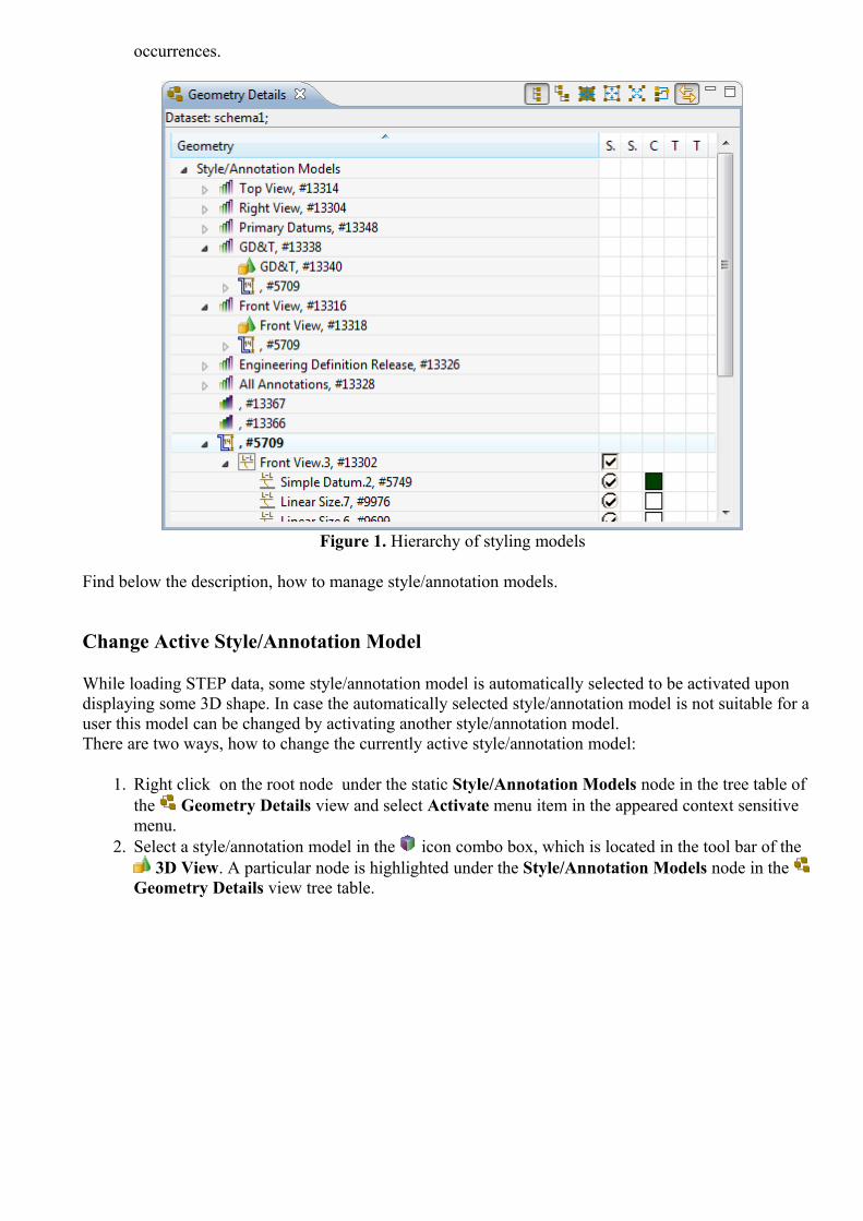
occurrences.
Figure 1. Hierarchy of styling models
Find below the description, how to manage style/annotation models.
Change Active Style/Annotation Model
While loading STEP data, some style/annotation model is automatically selected to be activated upon displaying some 3D shape. In case the automatically selected style/annotation model is not suitable for a user this model can be changed by activating another style/annotation model.There are two ways, how to change the currently active style/annotation model:
1. Right click on the root node under the static Style/Annotation Models node in the tree table of the Geometry Details view and select Activate menu item in the appeared context sensitive menu.
2. Select a style/annotation model in the icon combo box, which is located in the tool bar of the 3D View. A particular node is highlighted under the Style/Annotation Models node in the
Geometry Details view tree table.

Figure 2. Activate Style/Annotation Model ('Rod Assembly' - style model)
Create Style/Annotation Model
The editing of representation properties is performed in the context of the active style/annotation model. If there is no active model selected, a new style/annotation model is created as a root node under the Style/Annotation Models node. A new value of the representation property should be associated with the newly created style/annotation model. Note. The geometry with no style/annotation is available after STEP file is initially opened and no style/annotation model is selected for display or after the icon button is presses in 3D View tool bar.
Create new
This function creates a model with default presentation properties:
• Right click on the Style/Annotation Models node in the tree table of the Geometry Details view.
• Select the Create new menu item in the appeared context sensitive menu (see Figure 3).
Figure 3. Geometry Details view, Create new menu item
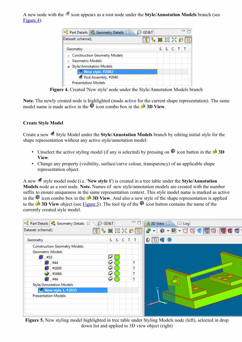
A new node with the icon appears as a root node under the Style/Annotation Models branch (see Figure 4).
Figure 4. Created 'New style' node under the Style/Annotation Models branch
Note. The newly created node is highlighted (made active for the current shape representation). The same model name is made active in the icon combo box in the 3D View.
Create Style Model
Create a new Style Model under the Style/Annotation Models branch by editing initial style for the shape representation without any active style/annotation model:
• Unselect the active styling model (if any is selected) by pressing on icon button in the 3D View.
• Change any property (visibility, surface/curve colour, transparency) of an applicable shape representation object.
A new style model node (i.e. 'New style 1') is created in a tree table under the Style/Annotation Models node as a root node. Note. Names of new style/annotation models are created with the number suffix to ensure uniqueness in the same representation context. This style model name is marked as active in the icon combo box in the 3D View. And also a new style of the shape representation is applied to the 3D View object (see Figure 5). The tool tip of the icon button contains the name of the currently created style model.
Figure 5. New styling model highlighted in tree table under Styling Models node (left), selected in drop down list and applied to 3D view object (right)

Note. The icon identifies, that this model contains styling only (visibility, surface/curve colour or transparency).
Create Annotation Model
The Annotation Model node is identified by the icon .Follow the routine to create a new annotation model:
• Make active an applicable style/annotation model which is marked with icon under the Style/Annotation Models branch in the Geometry Details view.
• Add some annotations in the 3D Viewer (for example a new annotation plane).
The initial icon of the activated model is changed to and the node of newly created annotation plane appears as a child node of the annotation model branch.
Create Style + Annotation Model
The model, which contains styling and annotations is identified by the icon (i.e. + ).The Style and Annotation Model is created if:
• Annotation Model is supplemented with some styling (visibility, colour or transparency), and • Style Model is supplemented with some annotation planes/occurrences.
To top
Rename Style/Annotation Model
There is a possibility to give a new name for a styling model. This will update style/annotation model name in the tree table of the Geometry Details view and icon combo box drop down list of the 3D View.Follow the routine to rename a style/annotation model:
• Select a style/annotation model node in the tree table. • Double click on the node or press F2 key. The editing mode is switched on. • Enter a new word or group of words that represent a new name of a style/annotation model and
press ENTER key.
The style/annotation model new name appears in the tree table and it is updated in the icon combo box drop down list ( 3D View).
To top
Editing Style/Annotation Model
The editing of a style/annotation model is available if this model is active. The following changes can be made in the Geometry Details view:
• Show/hide geometric models, annotation planes and occurrences (see Editing Visibility for details);
• Change surface colour for geometric models;

• Change curve colour for geometric models, annotation planes and occurrences;Note. See Editing Color for more details.
• Change transparency for geometric models (see Editing Transparency for more details).
Note. In case the style/annotation model is changed, the icon is applied automatically (i.e, the style model is supplied with annotations and vice versa, etc.).
To top
Link Style/Annotation Model
There is a possibility to link some style/annotation model with another style/annotation model, especially if the model does not have any style/annotation itself.Follow the routine to link a root styling model with an applicable styling model:
• Select a styling model to be linked with the root styling model. • Right click and select Copy menu item in the appeared context sensitive menu. • Select a root styling model to be linked with a copied to the clipboard model • Right click and select Link styled model menu item in the appeared context sensitive menu.
To top
Delete Style Model
You can delete an incorrect or a redundant style/annotation model with all linked models from the Geometry Details view. This will remove the style/annotation model from the tree and the icon drop down list in the 3D View. Note. If the active style/annotation model is deleted, this will change a selection in icon drop down list.Follow the routine to delete a style model:
• Select an applicable style/annotation model root node in the tree table under the Styling Models branch in the Geometry Details view.
• Right click and select Delete menu item in the appeared context sensitive menu.
Note. You can delete only the root style models. The child styling models can be unlinked only.
To top
Unlink Style/Annotation Model
Follow the routine to unlink the child style/annotation model:
• Select an applicable child node under the Style/Annotation Models branch. • Right click and select Unlink this model menu item in the appeared menu item.
The selected style/annotation model disappears from the tree table of the Geometry Details view.
To top

Clear Annotation Styles
The style for annotation elements can be applied individually or inherited from the parent element. For example, in case the annotation occurrence is not styled individually, it inherits a style from the parent annotation plane. If the style of the parent annotation plane is removed, the same happens with the style of the child annotation occurrence. If the annotation occurrence is styled individually (the coloured square in the Curve colour column), the remove function (Clear styles) of the annotation plane style does not influent the style of this annotation occurrence. The Clear styles recursively function on the parent element removes all styles, even the individually styled annotation occurrences of child elements.Follow the routine to remove styling of the parent element, where some child elements have their own set styles:
• Right click on a parent annotation element in the tree table. The context sensitive menu appears on the screen.
• Select one of:• Clear styles - remove styling for the currently selected element (see Figure 6). After the
parent styling is removed, individual styling is used for the child element, which are individually styled (see Figure 7).
• Clear styles recursively - remove styling for the currently selected element and all child objects recursively (even individually set styles).
Figure 6. Selected annotation occurrence with explicitly defined style (i.e. white colour rectangle), Context sensitive menu

Figure 7. Individually styled annotation occurrences (coloured rectangles)
To top
Copyright © 2009-2011 LKSoftWare GmbH. All Rights Reserved.DJSDAI is a registered trade mark of LKSoftWare GmbH.
9.8.5. Saved ViewsThe Saved view is a stored and retrievable specific orientation and magnification factor of a model. In IDA-STEP the saved view is stored as a child node of the particular styling model under the Styled Model branch in the Geometry Details view (see Figure 1).
Figure 1. Saved view (activated) under styled model branch
Activate Saved View
To retrieve the selected saved view:

• Right click on an applicable saved view node. • Select Activate this view menu item in the appeared context sensitive menu.
The selected saved view is activated together with the parent styled model. Note. The active saved view (and styled model) node fonts are displayed bold (see Figure 1).The particular saved view can be activated by selecting a particular item in the Styled model drop down list in the 3D View.
Rename Saved View
An incorrect name of an applicable saved view can be renamed:
• Select the saved view node. • Double click or press F2 key to turn editing mode On. • Edit the current text or enter a new one and press Enter key.
The new name of the saved view appears in the Styled Models tree.
Delete Saved View
To remove redundant or incorrect saved view:
• Right click on the saved view node. • Select Delete menu item in the appeared context sensitive menu.
The selected saved view node disappears from the Styled Models tree.
To top
Copyright © 2010-2011 LKSoftWare GmbH. All Rights Reserved.DJSDAI is a registered trade mark of LKSoftWare GmbH.
9.8.6. Editing Visibility
An object, selected in the Parts view, can be visible or not in the 3D View. The visibility is controlled by check-box in the tree table Show/Hide column of the Geometry Details view. There can be the following states of the Show/Hide column cell (see Figure 1):
1. Empty cell - there is no explicitly set style data. 2. Square box with a check mark inside - the row object is explicitly styled / visible;3. Square box without a check mark - the row object is explicitly styled / invisible;4. Square box with rounded corners, with a check mark inside - the row object has inherited
styling data / visible;5. Square box with rounded corners, without a check mark - the row object has inherited styling
data /invisible.

Figure 1. States of Show/Hide column cells
After un-checking the check-box, the selected object is made invisible in the 3D View. Note. All child geometry elements, like surfaces of cube are made invisible together with a selected object. There is a possibility to show/hide individual surfaces together with edges (see Figure 2).
Figure 2. Un-checked surface (in Geometry Details view) is hidden in 3D View
The following table shows the visibility state of the particular object, ‘visible’ or ‘invisible’ in the 3D View.
Child object Parent object Show?
False False False
False True False

True False True
True True True
Null Null True
Null False False
Null True True
False Null False
True Null True
- individually set to be invisible, - individually set to be visible, - not individually styled
For example, if a child object is individually set as visible, it is represented in the 3D view, in spite of the parent object is set invisible (see Figure 3).
Figure 3. Child object (highlighted in both views) individually set as visible, parent object ( #1029) is set as invisible
Another example, if child object is not individually styled, then parent styling is used, when deciding if show/hide the child object.
Clear Show/Hide value
The empty cell in the Show/Hide column is displayed right after a STEP file is initially opened and no styling model is selected. There is a possibility to make cells of the Show/Hide column empty
• Click on the empty squared check box on the root node under the Construction Geometry Models/Geometric Models branch.

Or
• Right click on the Show/Hide column cell of the root assembly node and select Clear menu item in the appeared context sensitive menu (see Figure 4).
Note. No other styling should be applied to the child row object. This Clear function is not available for annotation planes/occurrences under the Style/Annotation Models branch.
Figure 4. Clear menu item
The Clear operation can be used to make the state of a child row object from "explicitly set invisible" to "inherited invisible/visible" (the inherited state depends on the state of the parent row object).
Show/Hide Annotations and Annotation planes
The show/hide for annotations under the Styled Models branch works the similar way as written above:
• Show/Hide column for annotations should not be empty (of the activated styling model). • The state of cells should be:
• Square box with a check mark inside - the row object is explicitly styled / visible;• Square box without a check mark - the row object is explicitly styled / invisible. • Square box with rounded corners, with a check mark inside - the row object has
inherited styling data / visible;
If a particular annotation is used in several styling models, the visibility status of this annotation should be reused (i.e. visible/invisible in all styling models).Note. An annotation plane is not visible in the 3D View untill it is highlighted/activated.
To top
Copyright © 2009-2011 LKSoftWare GmbH. All Rights Reserved.DJSDAI is a registered trade mark of LKSoftWare GmbH.
9.8.7. Editing Color
The Geometry Details view tree table contains two columns for editing colour:

• Surface color - to change a surface fill colour;• Curve color - to change a surface edge or a wireframe colour.
Each object may have an inherited or an individually set colour. If the colour of a child object is not individually styled, the child object inherits the colour of a parent object. If the object has an individually styled colour, it does not inherit the colour of the parent element.The following content of the Surface color and Curve color columns is available (see Figure 1):
• Empty cell - there is no infomration about a surface colour for the selected row object. • Squared icon with colour inside - the style data for the row object contains information about a
colour (surface or curve). A colour of the icon matches the colour in data.• Rounded square icon with colour inside - the style data for the row object dos not contain
information about a colour (surface or curve). However, an upper row object has some colour set and that colour is inherited by th elower object (the current row object). A colour of the icon matches the inherited colour of the surface/edge.
Figure 1. Surface color and Curve Color columns with available content
Change colour
To change a colour for an applicable row object:
• Press on the particular column cell. The Color window appears on the screen (see Figure 2).

Figure 2. Color window
• Select an applicable colour by pressing on a colour square and press OK button. The selected colour is applied for the current row object.
To top
Remove colour
To remove a surface or edge colour:
• Right click on the colour cell. Note. Only the explicitly set colour (squared colour icon) can be removed.
• Select the Delete menu item in the appeared context sensitive menu.
The colour value is removed from the cell.
To top
Copyright © 2009-2010 LKSoftWare GmbH. All Rights Reserved.DJSDAI is a registered trade mark of LKSoftWare GmbH.
9.8.8. Editing TransparencyThe transparency of a particular object can be managed by selecting transparency level value from the list in the Transparency column of the Geometry Details view tree table (see Figure 1). Available values of transparency level are:
• Opaque, • 25 %,• 50 %, • 75 %, • 100 %.
Note. The Reset function sets default transparency level.
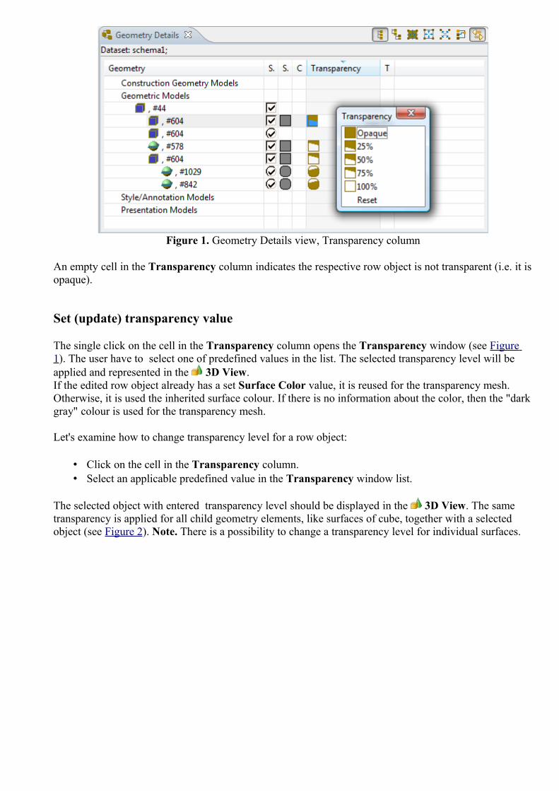
Figure 1. Geometry Details view, Transparency column
An empty cell in the Transparency column indicates the respective row object is not transparent (i.e. it is opaque).
Set (update) transparency value
The single click on the cell in the Transparency column opens the Transparency window (see Figure 1). The user have to select one of predefined values in the list. The selected transparency level will be applied and represented in the 3D View. If the edited row object already has a set Surface Color value, it is reused for the transparency mesh. Otherwise, it is used the inherited surface colour. If there is no information about the color, then the "dark gray" colour is used for the transparency mesh.
Let's examine how to change transparency level for a row object:
• Click on the cell in the Transparency column.• Select an applicable predefined value in the Transparency window list.
The selected object with entered transparency level should be displayed in the 3D View. The same transparency is applied for all child geometry elements, like surfaces of cube, together with a selected object (see Figure 2). Note. There is a possibility to change a transparency level for individual surfaces.
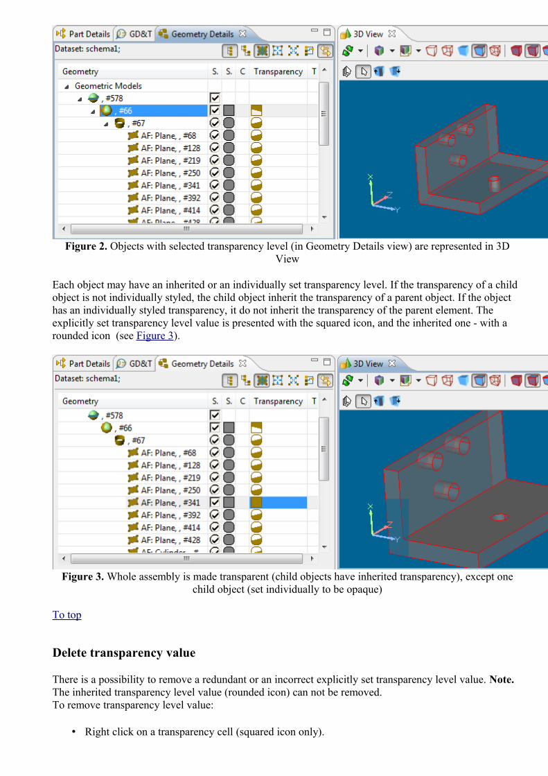
Figure 2. Objects with selected transparency level (in Geometry Details view) are represented in 3D View
Each object may have an inherited or an individually set transparency level. If the transparency of a child object is not individually styled, the child object inherit the transparency of a parent object. If the object has an individually styled transparency, it do not inherit the transparency of the parent element. The explicitly set transparency level value is presented with the squared icon, and the inherited one - with a rounded icon (see Figure 3).
Figure 3. Whole assembly is made transparent (child objects have inherited transparency), except one child object (set individually to be opaque)
To top
Delete transparency value
There is a possibility to remove a redundant or an incorrect explicitly set transparency level value. Note. The inherited transparency level value (rounded icon) can not be removed.To remove transparency level value:
• Right click on a transparency cell (squared icon only).

• Select Delete menu item in the appeared context sensitive menu.
The value from the cell is removed. Note. If there was no surface colour specified in the Surface Color cell, the colour for the transparency mesh is removed.
To top
Copyright © 2009-2010 LKSoftWare GmbH. All Rights Reserved.DJSDAI is a registered trade mark of LKSoftWare GmbH.
9.8.9. Editing Transformation Data
The transformation data for a shape representation are presented in the Transformation column in the Geometry Details view. In case the transformation data exist, the T letter is presented in the Transformation column cell. Detailed information is presented in the tool tips (see Figure 1).
Figure 1. Geometry Details view with Transformation column and tool tip (left side) and highlighted shape representation object (right side)
Follow the routine to change the transformation data for the selected shape representation object:
• Click on the cell in the Transformations column next to the shape representation object, which transformation data should be changed. The selected shape representation object is highlighted in the Geometry Details view tree table (see on the left of Figure 1) and also in the 3D View (see on the right of Figure 1).The 3D Transformation editor appears on the screen to change transformation data (see Figure 2).

Figure 2. 3D transformation editor
• Enter a number value into the X field to change the translation along X axis;• Enter a number value into the Y field to change the translation along Y axis; • Enter a number value into the Z field to change the translation along Z axis;• Enter a number value into the α field to change the rotation around X axis; • Enter a number value into the β field to change the rotation around Y axis; • Enter a number value into the γ field to change the rotation around Z axis.
• Press OK button to confirm your changes.
• The defined transformation data appears in the Transformations column tool tip and the view in the 3D View is updated (see Figure 3). Note. Units in the column are converted to the units, defined in the Quantity and Units preferences (Window -> Preferences -> Numbers -> Quantities and Units).
Figure 3. Transformation are changed (tool tip), new transformations applied in 3D View (right side)
To top
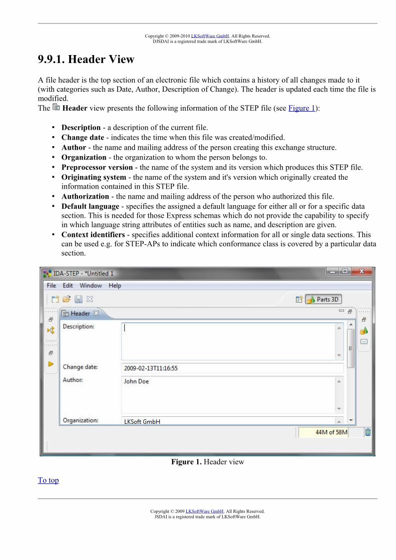
Copyright © 2009-2010 LKSoftWare GmbH. All Rights Reserved.DJSDAI is a registered trade mark of LKSoftWare GmbH.
9.9.1. Header ViewA file header is the top section of an electronic file which contains a history of all changes made to it (with categories such as Date, Author, Description of Change). The header is updated each time the file is modified. The Header view presents the following information of the STEP file (see Figure 1):
• Description - a description of the current file.• Change date - indicates the time when this file was created/modified. • Author - the name and mailing address of the person creating this exchange structure. • Organization - the organization to whom the person belongs to. • Preprocessor version - the name of the system and its version which produces this STEP file. • Originating system - the name of the system and it's version which originally created the
information contained in this STEP file. • Authorization - the name and mailing address of the person who authorized this file. • Default language - specifies the assigned a default language for either all or for a specific data
section. This is needed for those Express schemas which do not provide the capability to specify in which language string attributes of entities such as name, and description are given.
• Context identifiers - specifies additional context information for all or single data sections. This can be used e.g. for STEP-APs to indicate which conformance class is covered by a particular data section.
Figure 1. Header view
To top
Copyright © 2009 LKSoftWare GmbH. All Rights Reserved.JSDAI is a registered trade mark of LKSoftWare GmbH.

9.10.1. Log View
The Log view presents messages of IDA-STEP application which are relevant to the user (see Figure 1). Each message is displayed on a separate row, in date and time order (most recent first). The messages may be selected and copied in the Log view and then pasted to the preferable text editor.
Figure 1. Log view
Open the Log view by selecting in the main menu Window -> Show View -> Other -> General -> Log.
To top
Copyright © 2009 LKSoftWare GmbH. All Rights Reserved.JSDAI is a registered trade mark of LKSoftWare GmbH.
9.11.1. Maintenance Activities ViewAn Activity is the identification of the occurrence of an action that has taken place, is taking place, or is expected to take place in the future. The Maintenance Activities view presents a flat list of maintenance activities (See Figure 1). The first column presents the row element - maintenance activity identifier. Other columns contain data of the particular maintenance activity. The default column perspective contain the following columns:
• Id - specifies an identifier of the maintenance activity.• Name - specifies the word or group of words by which the maintenance activity is referred to. • Description - specifies additional information about the maintenance activity.• Chosen Method - the task method that specifies the procedure selected to carry out the
maintenance activity.• Subject - specifies the product as individual, which Element is under work.• Element - specifies the piece of product data that is under work.• Start Date - specifies the date when the maintenance activity is started.• End Date - specifies the date when the maintenance activity is finished. • Concerned Organization - specifies the organization object that is affected by the result of the
maintenance activity. • Supplying Organization - specifies the person in organization or an organization that carry
out the work. • Requestor - specifies the person in organization or an organization that requested the
maintenance activity.• Related Activity - specifies the related maintenance activity.

Figure 1. Maintenance Activities view (default columns)
To top
Copyright © 2009 LKSoftWare GmbH. All Rights Reserved.JSDAI is a registered trade mark of LKSoftWare GmbH.
9.11.2. Creating Maintenance Activity
Follow the routine to create a new maintenance activity element in the Maintenance Activities view table list (see Figure 1):
Figure 1. Maintenance Activities view with highlighted auto row
• Select the auto row in the table (see Figure 1 highlighted cell in the Id column). • Enter an identifier of the new maintenance activity element. • Press Enter key. A new maintenance activity element appears in the Maintenance Activities
view table (see Figure 2).
Figure 2. Created maintenance activity (highlighted)

To top
Copyright © 2009 LKSoftWare GmbH. All Rights Reserved.JSDAI is a registered trade mark of LKSoftWare GmbH.
9.11.3. Editing Maintenance Activity Data
Activate a Maintenance Activities view. Select an applicable maintenance activity element in the table list. You can edit the following:
• Enter a new or edit the current maintenance activity identifier in the Id column. • Enter the text, which defines the maintenance activity name into the Name column. • Enter additional information about the maintenance activity in the Description column. • The Chosen Method column value can be changed only by copying and pasting a particular
task method from the Tasks view (if available). • Select an applicable product as individual element from the drop down list in the Subject
column or press button to open Select entity dialog window to view the whole list of available product as individual elements. The value can be changed also by copying and pasting a particular
product as individual element from the Products view (if available). • Select an applicable assembly component, which parent assembly is a design of the Subject,
from the drop down list in the Element column or press button to open the Select entity dialog window to get the whole list of available elements. The value can be changed also by copying and pasting a particular assembly component, which parent assembly is a design of the Subject from the Part Details view (if available).
• Enter a new date and time by typing value or select it from the pop up table in the Start Date column.
• Enter a new date and time by typing value or select it from the pop up table in the End Date column.
• The Concerned Organization column value can be changed only by copying and pasting a particular organization from the Persons and Organizations view (if available).
• The Supplying Organization column value can be changed only by copying and pasting a particular person in organization or an organization from the Persons and Organizations view (if available).
• The Requestor column value can be changed only by copying and pasting a particular person in organization or an organization from the Persons and Organizations view (if available).
• Enter a new or edit the current value in the Value column edit box. The units may be changed by using Unit wizard.
To top
Copyright © 2008 LKSoftWare GmbH. All Rights Reserved.JSDAI is a registered trade mark of LKSoftWare GmbH.
9.11.4. Removing Maintenance Activity
Activate the Maintenance Activities view. Follow the routine to remove a particular maintenance activity element form the table:
• Select a maintenance activity element in the table list. • Right click on the Id column. • Select the Delete menu item in the appeared context sensitive menu.

The selected maintenance activity element is removed from the Maintenance Activities view table list.
To top
Copyright © 2009 LKSoftWare GmbH. All Rights Reserved.JSDAI is a registered trade mark of LKSoftWare GmbH.
9.12.1. Part Details View
The Part Details view content is dependent on the selection in the Parts view. The Part Details view presents a hierarchy of part definitions of a part version, selected in the Parts view (see Figure 1). The Part Details view title presents the following information:
• Datasets: the currently opened dataset; • Part version: the part version, selected in the Parts view, details.
Default Part Details view columns:
• Id - part definition/part definition component identifier. The check box in the front of the first column controls visibility and transparency of an assembly component.
• Definition - the definition, which the component is derived from.• Transformations - the transformation data of the part definition component.
Figure 1. Selected part version in the Parts view and it's definitions in the Part Details view

If the opened XIM or STEP file contains PCA design data, the Part Details view may display electronical components with terminals (see Figure 2). By default, Part Details view shows only the flat list of electronical components. To view related electronical component terminals, press Show Shape Aspects button in the view tool bar.
Figure 2. Part Details view with electronical component terminals
The Part Details view is is capable to display following additional element types, if the special Show Shape Aspects button is pressed in the Part Details view tool bar (see Figure 3):
• shape aspect (datums, datum features, composite shape aspects and derived shape aspects); • dimensions (linear distance, diameter size etc.); • geometric tolerances (perpendicularity, position etc.).
Note. This feature is experimental and may be unstable. It can be changed/removed in upcoming releases.
Figure 3. Part Details view with shape aspects
A list of possible node types:
• shape aspect,• angularity tolerance, • circular runout tolerance, • cylindricity tolerance,

• concentricity tolerance, • datum feature object, • datum object, • datum reference, • dimensional size object, • flatness tolerance, • geometric tolerance object, • line profile tolerance object, • linear dimension object, • parallelism tolerance object, • perpendicular object, • position tolerance, • roundness tolerance object, • symmetry tolerance object, • straightness tolerance object, • stratum profile tolerance object, • total runout tolerance.
Tool tips
The Part Details view has a tool tip over each node. Component nodes (and transformations) have a single line tool tip that shows just the text, which appears in the ID column. All other nodes (presumably related to shape aspects) have two-line tool tips:
• the first line shows a type, a name and a hash code; • the second line shows if any geometry is associated with the node (i.e., if clicking on the node
would result in any selection/highlight event in Geometry Details view or 3D view). The second line reads "Has geometry:" and the possible values are "YES" or "NO".
Tool bar
The table below presents the available tool bar buttons in the Part Details view.
Button icon Description
Expand All Expand all tree nodes.
Collapse All Collapse all tree nodes.
Current action
Determine the kind of actions, either to make invisible or to set transparency to some level. The predefined values are: invisible, Transparent by 25 %, Transparent by 50 %, and Transparent by 75 %.The default value is invisible.
Show Shape Aspects see Figure 2
Link with When this option is turned On, the selection in the Part Details view is represented in the 3D View and vice versa.

Other Views.
To top
Copyright © 2006-2010 LKSoftWare GmbH. All Rights Reserved.JSDAI is a registered trade mark of LKSoftWare GmbH.
9.12.2. Selection
The selection of some part or assembly in the Parts Details view initiates the highlighting of corresponding geometry objects in the 3D View and related geometry elements in the Geometry Details view (see Figure 1).
Figure 1. Selected part in Part Details view triggers highlighting of corresponding geometry elements in other views
If a part is modeled by using feature based paradigm, an applicable shape aspects can be selected in the Parts Details view and then cross-highlighted in other views (see Figure 2).

Figure 2. Selected shape aspect in Part details view initiates highlighting of associated geometry element/object in other views
To top
Copyright © 2009 LKSoftWare GmbH. All Rights Reserved.JSDAI is a registered trade mark of LKSoftWare GmbH.
9.12.3. Visibility and TransparencyWith the Viewer Pro 3D feature you can control the visibility and transparency of assembly components. For this a check box shows up in each line of the assembly tree together with a combo box in the tool bar. If the check box is set, the corresponding assembly component is visible. If it is unchecked, the corresponding assembly component get either invisible or transparent dependent on the state of the Visibility combo box (see Figure 1). Note. This capability is only available if the Show Shape Aspect button in the tool bar of the Part Details view is not pressed.

Figure 1. Check box to control visibility and transparency and button to select action type
The Visibility combo box can have one of these states:
• Invisible (this value is the default value), • Transparency by 25%, • Transparency by 50%, • Transparency by 75%.
Changing the value of the Visibility combo box has by itself no effect. Only when un-setting one of the check boxes the actual state of the combo box is copied for the affected assembly component. So it is possible to make some components invisible and have other components on different levels of visibility.In principle visibility and transparency of assembly components can also be controlled in the Geometry Details view, but controlling them directly in the assembly tree is typically much easier.
Figure 2. Example on how to make an assembly component transparent
Figure 2 shows an example on how to make an assembly component transparent. First set the visibility combo box to 50% transparency and then unset the check box of an assembly component.
When making an intermediate assembly component that is itself an assembly invisible or transparent, the whole subtree inherits this information. But you can nevertheless change the state of it's leaves afterwards.

Note. The visibility/transparency is directly coupled with Geometric Details view, independent on whether the user has opened it or not.
To top
Copyright © 2009 LKSoftWare GmbH. All Rights Reserved.JSDAI is a registered trade mark of LKSoftWare GmbH.
9.12.4. Editing Part Details
Activate the Part Details view to edit data. You can make the following actions for the selected object in the tree table:
• Product definition - the root node in the Part details view: • Enter a new or edit the current identifier in the Id column (see Figure 1).
Figure 1. Part Details view, selected root node in Id column
• Product definition component - the component beneath the root node (i.e. second, third and deeper level node):
• Enter a new or edit the current identifier in the Id column. • Select a new definition for the component in the Definition column:
• Select an applicable item from the drop down list.
Or
• Press the button next to the text field. The Select entity dialog window appears on the screen (see Figure 2):

Figure 2. Select entity dialog window
• Select an applicable entity in the list. You can use the filter on the top section of the window to filter out particular entities.
• Press OK button. The selected entity data appears in the Definitions column. The particular 3D object appears in the 3D View.
• Edit component transformation data in the Transformations column: • Click on the cell in the Transformations column. The 3D Transformation editor
appears on the screen to change transformation of a 3D object if needed (see Figure 3):
Figure 3. 3D transformation editor
• Enter a number value into the X field to change the translation along X axis;• Enter a number value into the Y field to change the translation along Y axis; • Enter a number value into the Z field to change the translation along Z axis;• Enter a number value into the α field to change the rotation around X axis; • Enter a number value into the β field to change the rotation around Y axis; • Enter a number value into the γ field to change the rotation around Z axis.

• Press OK button to confirm your changes. The transformation data appears in the Transformations column.Note. Units in the column are converted to the units, defined in the Quantity and Units preferences (Window -> Preferences -> Numbers -> Quantities and Units)
To top
Copyright © 2009 LKSoftWare GmbH. All Rights Reserved.JSDAI is a registered trade mark of LKSoftWare GmbH.
9.12.5. Create Assembly from Parts
IDA-STEP allows user to select multiple parts from the file and then create assembly from them by creating component from each part with zero transformation in the new assembly.
Follow the routine to create an assembly from selected parts:
• Press Create assembly from parts... button in IDA-STEP main tool bar. • The Create assembly dialogue window appears on the screen (see Figure 1):
• Enter an assembly identifier into the Assembly ID text field. By default the text newID is entered into this field.
• Select an applicable parts to be included into the assembly by pressing CTRL + selecting parts. By default all parts are selected.
• Press OK button to create an assembly.
Figure 1. Create assembly page
To top

Copyright © 2011 LKSoftWare GmbH. All Rights Reserved.JSDAI is a registered trade mark of LKSoftWare GmbH.
9.12.6. Adding Component
The Part Details view content is dependent on the selection in the Parts view. If the selected part version in Parts view has a part definition, it is presented as a root node in the Part Details view. In other case, you have to create a part definition as a root node to be able to add new components.Follow the routine to add a root node in the Part Details view:
• Select an autorow in the Part Details view (see Figure 1).
Figure 1. Part Details view, autorow
• Enter an applicable identifier for a part definition into Id column and press Enter key. The root node is created (see Figure 2).
Figure 2. Created root node
Now you can add components to the part definition.
• Right click on the root node. Select Add component menu item in the appeared context sensitive menu (see Figure 3) or select the autorow node under the component you are going to add a new component to.
Figure 3. Context sensitive menu with selected Add component menu item
• Enter an identifier of a new component into Id column (see Figure 4) and press Enter key.

Figure 4. Created new component
• Select a definition for the component in the Definition column: • Select an applicable item from the drop down list.
Or
• Press the button next to the text field. The Select entity dialog window appears on the screen (see Figure 5):
Figure 5. Select entity dialog window
• Select an applicable entity in the list. You can use the filter on the top section of the window to filter out particular entities.
• Press OK button. The selected entity data appears in the Definitions column (see on the left side of Figure 6). The particular 3D object appears in the 3D View (see on the right side of Figure 6).

Figure 6. Selected definition in the definition column
• Edit component transformation data in the Transformations column: • Double click on the cell in the Transformations column. The 3D Transformation
editor appears on the screen to change transformation of a 3D object if needed (see Figure 7):
Figure 7. 3D transformation editor
• X - translation along X axis;• Y- translation along Y axis;• Z - translation along Z axis;• Units - measure units (measure units, assigned in STEP file);• α - rotation around X axis; • β - rotation around Y axis; • γ - rotation around Z axis.
Note. Rotation units are degrees (º).• Press OK button to confirm your changes. The transformation data appears in the
Transformations column.Note. Units in the column are converted to the units, defined in the Quantity and Units preferences (Window -> Preferences -> Numbers -> Quantities and Units).
The Add component function can be used not only for adding components for the root part definition. You can add additional components for an applicable part definition component (see Figure 8).

Figure 8. Assembly component (i.e. 'NUT_BOLT..'), selected in Part Details view and highlighted in 3D View
To top
Copyright © 2009 LKSoftWare GmbH. All Rights Reserved.JSDAI is a registered trade mark of LKSoftWare GmbH.
9.12.7. Add 3D Part to LibraryIDA-STEP presents possibility to add 3D parts to the 3D Parts Library (see Manage 3D Part Libraries).To populate 3D parts library:
• Select a 3D part/assembly entry (top node) in the Part Details view table. • Right click and select the Add 3D Part to Library item in the appeared context sensitive menu.
The Import 3D Part wizard page appears on the screen (see Figure 1) with the 3D Part library hierarchy (libraries with categories, situated beneath):
Figure 1. Import 3D Part wizard page with library hierarchy
• Expand an applicable tree branch, which presents a library (top node). In case the part should not be classified, select library name, otherwise select a category name.
• Press the OK button to confirm the selection and close the wizard page. The selected part is added to the library. To view results use the main menu File -> Manage libraries -> 3D Part Libraries....

See also 3D Part Libraries.
To top
Copyright © 2011 LKSoftWare GmbH. All Rights Reserved.JSDAI is a registered trade mark of LKSoftWare GmbH.
9.12.8. Copying and Pasting
There are the following Copy / Pasting possibilities in the Part Details view:
• Copy/Paste part definition • Copy/Past part definition component.
Note. IDA-STEP presents possibility to copy part definition or component in the Part Details view in one STEP file and paste into another STEP file.
Copy/Paste part definition
Follow the routine to copy/paste the root node in the tree table of the Part Details view:
• Select the root node. • Right click and select Copy menu item in the appeared context sensitive menu or press CTRL +
C keys. • Select the autorow as a root node in the tree table. If the autorow is not in the root branch, right
click on the autorow and select Move to root menu item in the appeared context sensitive menu. • Right click and select Paste menu item in the context sensitive menu or press CTRL + V keys.
The copy of the selected part definition appears in the tree table (see Figure 1).
Figure 1. Copy of part definition in Part Details view
To top
Copy/Paste part definition component
Follow the routine to copy/paste a part definition component in the Part Details view.
• Select an applicable component. • Right click and select Copy menu item in the appeared context sensitive menu or press CTRL +
C keys.

• Right click on the destination object (part definition or part definition component) in the tree table.• Select Paste menu item in the context sensitive menu or press CTRL + V keys. The copy of the
selected component appears in the tree table (see Figure 2).
Figure 2. Copy of part definition component
To top
Copyright © 2009 LKSoftWare GmbH. All Rights Reserved.JSDAI is a registered trade mark of LKSoftWare GmbH.
9.12.9. RemovingTo remove a redundant or incorrect product definition or product definition component from the tree table in the Part Details view:
• Select an object you want to remove. • Right click and select Delete menu item in the context sensitive menu or press Delete key. The
selected object is removed from the tree table.
To top
Copyright © 2009 LKSoftWare GmbH. All Rights Reserved.JSDAI is a registered trade mark of LKSoftWare GmbH.
9.13.1. Parts View
The Parts view presents the table list of part versions, available in the currently opened dataset (see Figure 1). The active dataset name is presented in the Parts view title.The default columns, presented in the Parts view:
• Id - an identifier of a part version;• Name - a word or words by which a part version is designated and distinguished from others; • Version - a part version designation;• ID Owner -an organization which has legal ownership of a part version and has the right to use it
and has full control over it; • Creator - an organization, which is a creator of the part version;• Security - the level of confidentiality that is required in order to protect part version data against
unauthorized usage; • <class attributes> - the columns appears if the list of part versions belong to the classification,
where some class attributes are created.

Figure 1. Parts view
By default, the Parts view presents only the table list of part versions, but if you press Show classifications button, a hierarchy of classifications appears on the left side of the window (see Figure 2).
Figure 2. Parts view with hierarchy of classifications
Tool bar
Button Icon Description
Display only root parts
Display only assembly parts

Display only piece parts
Show classifications
Link with Other Views
When this option is turned On, the Part Details view presents a hierarchy of part definitions of the part version selected in the Parts view.
Open a new window of the active view
To top
Copyright © 2006-2009 LKSoftWare GmbH. All Rights Reserved.JSDAI is a registered trade mark of LKSoftWare GmbH.
9.13.2. Part Classifications
A classification in is a systematic arrangement of parts in groups or categories according to criteria. Each classification may have sub-classification and classification attributes, which appear as an additional column in a table list of parts. Classifications are grouped into a particular classification system.The Parts view presents a hierarchy of part classification on the left side of the window and a table list of available part versions on the right side of the window, after the Show Classifications button is switched On (see Figure 1).

Figure 1. Part Classification windowTo top
Classification Hierarchy
A classification hierarchy presents a classification relationship between class as a member, the specification of all the members of the class (see Figure 1). The classification hierarchy is visible in the
Parts view only if the special button, i.e. Show Classifications is switched On.Click on an applicable classification in the tree to view associated sub-classifications and classified
part versions in the table list:
• Click on a parent classification to view all part versions, associated to this classification and sub-classifications, situated beneath (see Figure 2).
Figure 2. Parent classification 'tools' presents parts 'stick' and 'tip' which belong to 'special' classification
• Click on a "leaf" classification - the table list presents only the list of part versions that are associated to this "leaf" classification.
• You can view the list of all part versions (classified and not classified) after you unselect all nodes in the hierarchy by mouse click on the empty tree area.
To top
Class Attributes
A classification attribute specifies an assignment to product data.The class attributes may be situated under an applicable classification branch in the classification hierarchy:
• Click on an applicable classification to view associated class attributes under the branch. Also you can see all associated class attributes in the table list as separate columns (see Figure 3).

Note 1. The table list shows columns of those class attributes, which are associated to the selected classification. The class attributes of sub classification do not appear in the columns (see Figure 2). Note 2. A sub-classification inherits the class attributes from the parent classification.
• Click on a class attribute to view a page with the class attribute details (see Figure 4).
Figure 3. Class attribute 'weight' as a column 'weight' in the table list
Figure 4. Selected class attribute in a hierarchy (left) and Details of class attribute (right)
To top
List of Parts
The table list on the right side of the Part Classification window presents the list of available parts with their attributes. Each part may have several versions, that are identified in the Version column. The part version is a subject to a part. A new part version will be assigned automatically to the classification the previous version was assigned to. The part is removed from the dataset after all version of this part are removed. If you move one part version to a particular classification - all part versions will be moved together.If you click on a particular part in a table list, the classification (all classifications), for which the
part is assigned to, is highlighted in the tree (see Figure 5). If you click on a particular classification node, you can view the list of parts, associated to this classification.The list of all parts, which are classified and not, appears if no nodes are selected in the tree. If any node is selected, you can unselect it by mouse click on the empty tree area.

Figure 5. Part 'paint' belongs to 'materials' classification
To top
Copyright © 2009 LKSoftWare GmbH. All Rights Reserved.JSDAI is a registered trade mark of LKSoftWare GmbH.
9.13.3. Creating Part Version You have possibility to create:
• unclassified part version , which does not belong to any classification
Or
• classified part version , which is associated to a particular classification while creation process.
Creating Unclassified Part Version
Follow the routine to create a part version:
• Unselect selected nodes in a part classification hierarchy by mouse click on the empty tree area. The list of available part versions appears in the table.
• Find the autorow with an asterisk at the end of the list (see Figure 1). • Enter data into columns: Id, Name, Version and classification attribute if any.
Figure 1. Row with an asteriskTo top

Creating Classified Part Version
Follow the routine to create a part version for the selected classification:
• Click on an applicable classification node in a hierarchy. The table with a list of part versions appears on the right side of the window.
• Find the autorow with asterisk at the end of the list (see Figure 1). • Enter data into columns: Id, Name, Version and classification attribute if any.
To top
Copyright © 2006-2009 LKSoftWare GmbH. All Rights Reserved.JSDAI is a registered trade mark of LKSoftWare GmbH.
9.13.4. Creating New Version
Follow the routine to create a new version of a part version:
• Select a part version in a table list. • Right click on the selected part version to open a context sensitive menu (see Figure 1).
Figure 1. Context sensitive menu to create a new part version
• Select New version menu item. A new line with the same data (Id, Name) appears under the previous part version row. The Version column cell is marked with an asterisk (see Figure 2):
• Enter a number of the version into the Version cell.
Note. A new part version will be assigned automatically to the classification, the previous version was assigned to.
Figure 2. Created new part version row

To top
Copyright © 2006-2009 LKSoftWare GmbH. All Rights Reserved.JSDAI is a registered trade mark of LKSoftWare GmbH.
9.13.5. Copying and Pasting
The following copy / pasting functionality is implemented in the Parts view:
• Copy / paste part version • Copy / paste part classification object: classification system, classification, class attribute
Copy / Paste Part Version
IDA-STEP presents possibility to copy an applicable part version and paste it not only inside the currently opened Parts view, but also into another opened STEP file Parts view.Follow the routine to copy and paste a part version in the Parts view:
• Select an applicable part version. • Right click and select Copy menu item in the appeared context sensitive menu or press CTRL +
C keys. • Right click on the autorow at the bottom of the table.• Select Paste menu item in the context sensitive menu or press CTRL + V keys. The copy of the
selected part version appears in the table list (see Figure 1).
Note. The copied part version contains all data of the initial part version (Name, part definitions, components, shapes and etc. see Figure 1).

Figure 1. Copy of the part version in Parts view
To top
Copy / paste part classification object
First of all, press Show classifications button in the Parts view toolbar to see a part classification hierarchy on the left side of the Parts view.Follow the routine to copy and paste an applicable object in the part classification hierarchy:
• Select an applicable object in the part classification hierarchy ( classification system, classification or class attribute).
• Right click and select Copy menu item in the appeared context sensitive menu or press CTRL + C keys.
• Select a destination place in the part classification hierarchy. • Right click and select Paste menu item in the appeared context sensitive menu or press CTRL +
V keys. The copy of some part classification object is made with all related objects.
Note. If the destination place is selected not correctly, the pasting is not allowed, i.e. Paste menu item is disabled. For example, a classification system can be pasted only as a root node. If you try to paste it on some other object in the hierarchy, simply it is not allowed.
To top
Copyright © 2009 LKSoftWare GmbH. All Rights Reserved.JSDAI is a registered trade mark of LKSoftWare GmbH.
9.13.6. Editing Data
You can edit entered data in the Parts window:
• Classification system data • Classification data • Classification attribute data • Part version data
Edit Classification System Data
Follow the routine to edit a classification system name:
• Double click on a classification system node in the tree. • Edit the current or enter a new name. • Press Enter key to turn off edit mode.
Edit Classification Data
Follow the routine to edit a classification name:
• Double click on a classification node in the tree.

• Edit the current or enter a new name. • Press Enter key to turn off edit mode.
Edit Class Attribute Data
Follow the routine to edit a class attribute name:
• Double click on a classification attribute node in the tree. The class attribute name is selected (see Figure 3).
• Edit the current or enter a new name. • Press Enter key to turn off edit mode. A new name is set for the selected class attribute in the tree
and in the title of class attribute column in the table list.
Or
• Click on a classification attribute node in the tree. The Details of classification attribute page appears on the right side of the Part Classification window:
• Enter the classification attribute identifier into Id field. • Edit or enter a new name in the Name field. • Enter descriptive information about the classification attribute in the Description field.
To top
Edit Part Data
Follow the routine to edit a part version data:
• Double click on an applicable column of the part version you want to edit the current text or just type text to enter new values:
• Id - edit the current or enter new identifier. • Name - edit the current or enter new part name. • Version - edit the current or enter new version identifier. • <class attribute name> - enter or edit the current value in the field and select an
applicable unit from the list. • ID Owner, Creator - select an applicable value from the drop down list or press the
button next to the text field and select an applicable organization from the appeared Select entity dialog window.
• Press Enter key to go down to the next cell.
Note. If you change an identifier and/or a name of the part version, which has several versions, the changes are applied to all versions of that part.
To top
Copyright © 2006-2009 LKSoftWare GmbH. All Rights Reserved.JSDAI is a registered trade mark of LKSoftWare GmbH.
9.13.7. Assigning Part to Classification
Follow the routine to assign a part version to an applicable classification:
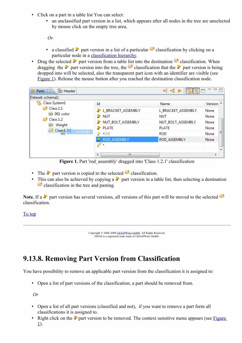
• Click on a part in a table list You can select: • an unclassified part version in a list, which appears after all nodes in the tree are unselected
by mouse click on the empty tree area,
Or
• a classified part version in a list of a particular classification by clicking on a particular node in a classification hierarchy.
• Drag the selected part version from a table list into the destination classification. When dragging the part version into the tree, the classification that the part version is being dropped into will be selected, also the transparent part icon with an identifier are visible (see Figure 1). Release the mouse button after you reached the destination classification node.
Figure 1. Part 'rod_assembly' dragged into 'Class 1.2.1' classification
• The part version is copied to the selected classification. • This can also be achieved by copying a part version in a table list, then selecting a destination
classification in the tree and pasting.
Note. If a part version has several versions, all versions of this part will be moved to the selected classification.
To top
Copyright © 2006-2009 LKSoftWare GmbH. All Rights Reserved.JSDAI is a registered trade mark of LKSoftWare GmbH.
9.13.8. Removing Part Version from ClassificationYou have possibility to remove an applicable part version from the classification it is assigned to:
• Open a list of part versions of the classification, a part should be removed from.
Or
• Open a list of all part versions (classified and not), if you want to remove a part form all classifications it is assigned to.
• Right click on the part version to be removed. The context sensitive menu appears (see Figure 1).
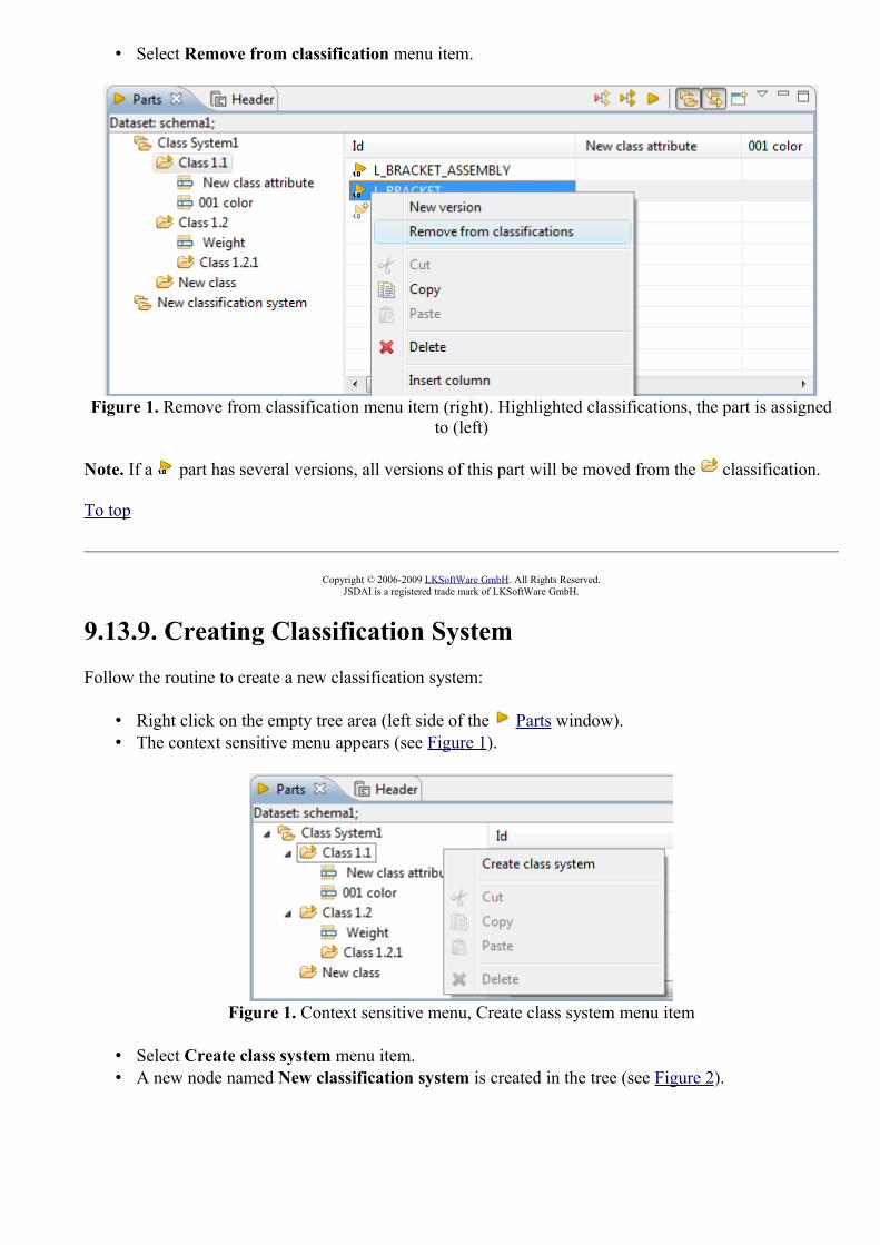
• Select Remove from classification menu item.
Figure 1. Remove from classification menu item (right). Highlighted classifications, the part is assigned to (left)
Note. If a part has several versions, all versions of this part will be moved from the classification.
To top
Copyright © 2006-2009 LKSoftWare GmbH. All Rights Reserved.JSDAI is a registered trade mark of LKSoftWare GmbH.
9.13.9. Creating Classification SystemFollow the routine to create a new classification system:
• Right click on the empty tree area (left side of the Parts window). • The context sensitive menu appears (see Figure 1).
Figure 1. Context sensitive menu, Create class system menu item
• Select Create class system menu item. • A new node named New classification system is created in the tree (see Figure 2).

Figure 2. New classification system, named 'New classification system' in the tree
• To change name of the newly created classification system double click on the node and enter an applicable name.
To top
Copyright © 2006-2009 LKSoftWare GmbH. All Rights Reserved.JSDAI is a registered trade mark of LKSoftWare GmbH.
9.13.10. Creating ClassificationYou can create new top level classification or sub -classification in the part classification hierarchy.
Creating Top Level Classification
Follow the routine to create a top level classification:
• Right click on the classification system node in the tree. The context sensitive menu appears (see Figure 1).
• Select Create class menu item.
Figure 1. Context sensitive menu, invoked from dataset branch
• A new node named New class is created in a hierarchy (see Figure 2).
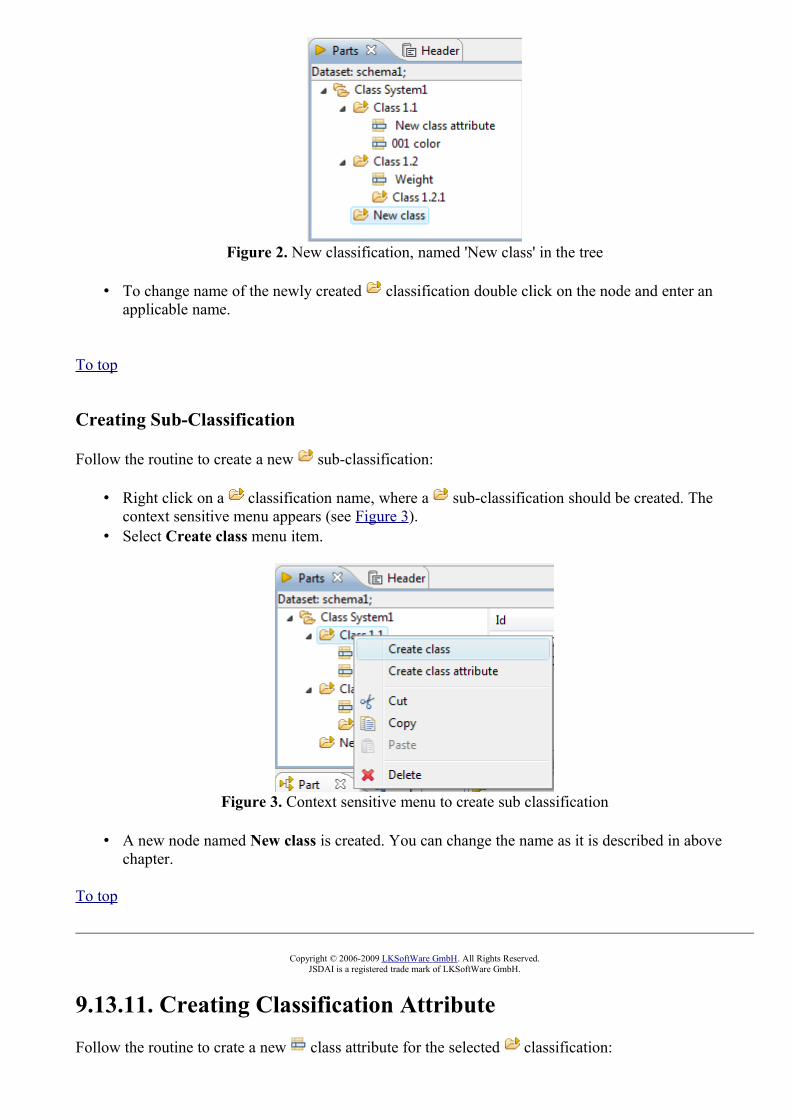
Figure 2. New classification, named 'New class' in the tree
• To change name of the newly created classification double click on the node and enter an applicable name.
To top
Creating Sub-Classification
Follow the routine to create a new sub-classification:
• Right click on a classification name, where a sub-classification should be created. The context sensitive menu appears (see Figure 3).
• Select Create class menu item.
Figure 3. Context sensitive menu to create sub classification
• A new node named New class is created. You can change the name as it is described in above chapter.
To top
Copyright © 2006-2009 LKSoftWare GmbH. All Rights Reserved.JSDAI is a registered trade mark of LKSoftWare GmbH.
9.13.11. Creating Classification Attribute
Follow the routine to crate a new class attribute for the selected classification:

• Right click on an applicable classification node. The context sensitive menu appears (see Figure 1).
• Select Create class attribute menu item.
Figure 1. Context sensitive menu to create new class attribute
• The class attribute, named New class attribute appears in the hierarchy. Also a new column of the created class attribute appears in the table list of the classification the class attribute is assigned to (see Figure 2).
Figure 2. 'New class attribute' in the classification hierarchy (left) and in the table list (right)
• Click on the created class attribute to open the Details of classification attribute page (see Figure 3):
• Enter classification attribute identifier into Id field. • Edit or enter a new name in the Name field. • Enter descriptive information about the classification attribute in the Description field.

Figure 3. Details of classification attribute pageTo top
Copyright © 2006-2009 LKSoftWare GmbH. All Rights Reserved.JSDAI is a registered trade mark of LKSoftWare GmbH.
9.13.12. Deleting
Follow the routine to delete an incorrect or redundant element in the Parts window:
• Right click on the element you want to remove in the tree / table list: • classification system node,• classification node, • classification attribute node, • part in a table list.
• The context sensitive menu appears (see Figure 1). • Select Delete menu item.
Figure 1. Context sensitive menu, Delete menu item
To top
Copyright © 2006-2009 LKSoftWare GmbH. All Rights Reserved.JSDAI is a registered trade mark of LKSoftWare GmbH.
9.13.13. Moving
Moving can be performed by dragging and dropping selected objects in the Parts window:

• Moving classification - to change task location in the hierarchy. • Moving classification attribute - to change the location of the selected classification
attribute. • Move part versions - to assign a part version to a classification or remove a part version form
a classification .
To top
Copyright © 2006-2009 LKSoftWare GmbH. All Rights Reserved.JSDAI is a registered trade mark of LKSoftWare GmbH.
9.14.1. Passage Technologies View
The Passage technologies view (available by selecting in the main menu bar Window -> Show view -> Other then under PCB Layer Stack node) presents a list of passage technologies (see Figure 1). The first column presents the row element - passage technology, other columns contain data of the particular passage technology. The default column perspective contain the following columns:
• Id - specifies an identifier of the passage technology.• Plating - specifies if the passage is plated or not. • Min size - specifies the finished passage extent for the passage technology. • Min Interior - specifies the minimum interior extent for the passage technology. This
characteristic is available only for a passage, which technology type is via. • Terminus - specifies the passage terminus condition for the passage technology. • Deposition thickness - specifies the finished deposition thickness value for the passage
technology. • Deposition Material- specifies the passage deposition material identification.• Electrical conductivity - specifies the passage technology conductivity classification for
deposition material identification for a passage. • Filling Material- specifies the passage filling material identification for the passage technology.• Electrical conductivity - specifies the passage technology conductivity classification for filling
material identification for a passage.
Figure 1. Passage technologies view (default columns)To top
Copyright © 2009 LKSoftWare GmbH. All Rights Reserved.JSDAI is a registered trade mark of LKSoftWare GmbH.
9.14.2. Creating Passage Technology
Follow the routine to create a new passage technology element in the Passage Technologies view tree table (see Figure 1):

Figure 1. Passage technologies view tree table with highlighted auto row
• Select the auto row in the tree table (see Figure 1 highlighted cell in the Id column). • Click on the selected auto row to enter into the edit mode. • Enter an identifier of the new passage technology element. • Press Enter key. A new passage technology element appears in the Passage Technologies
view tree table (see Figure 2). The Type column is filled with a default value automatically. The value can be changed together with other passage technology data.
Figure 2. Created passage technology element (highlighted)
To top
Copyright © 2009 LKSoftWare GmbH. All Rights Reserved.JSDAI is a registered trade mark of LKSoftWare GmbH.
9.14.3. Editing Passage Technology Data
Activate the Passage Technologies view. Select an applicable passage technology element in the tree table. You can edit the following:
• Enter a new or edit the current passage technology identifier in the Id column. • Select an applicable value in the Type combo box. You can not enter a new value. • Click with mouse on the Plated column to set an applicable value. • Enter a new or edit the current value of the finished passage extent in the Min size column. You
can also select a new tolerance value or/and change units. • Enter a new or edit the current value of the minimum interior extent in the Min interior column.
You can also select a new tolerance value or/and change units. • Select a new passage terminus condition value in the Terminus column. • Enter a new or edit the current finished deposition thickness value in the Deposition thickness
column. You can also select a new tolerance value or/and change units. • Select or enter a new value of a deposition material identification in the Deposition Material
column. If the selected deposition material contains the associated electrical conductivity

classification, the Electrical conductivity column cell is filled with a predefined value. • Select an applicable value of the electrical conductivity classification in the Electrical
conductivity column. The selected value is associated to the current deposition material identification, presented in the Deposition Material column.
• Select or enter a new value of a deposition material identification in the Filling Material column. If the selected filling material contains the associated electrical conductivity classification, the Electrical conductivity column cell is filled with a predefined value.
• Select an applicable value of the electrical conductivity classification in the Electrical conductivity column. The selected value is associated to the current filling material identification, presented in the Filling Material column.
To top
Copyright © 2009 LKSoftWare GmbH. All Rights Reserved.JSDAI is a registered trade mark of LKSoftWare GmbH.
9.15.1. Passages View
The Passages view (available by selecting in the main menu bar Window -> Show view -> Other then under PCB Layer Stack node) presents a tree table with a hierarchy of passages, referenced by a particular design stack model, which is identified in the top section of the Passages view window (see Figure 1). Note: The data appears in the Passages view only after an applicable design stack model is selected in the Design Stack Models view.First column presents row element - passage. Other columns contain the assigned data for the particular passage element.The default column perspective contain the following columns:
• Id - an identifier of a passage.• From - specifies the top most stratum the passage is passing trough, if the passage orientation is
top-bottom, and the bottom most stratum otherwise.• To - specifies the top most stratum the passage is passing through, if the passage orientation is
bottom-top, and the top most stratum otherwise.• Connected Ring Size - specifies a size of the connected minimum annular ring of the passage.• Unconnected Ring Size - specifies a size of the unconnected minimum annular ring of the
passage.• Macro - specifies an allocated technology of the passage.• Type - specifies a technology type value of the passage. The available values: border, component
termination, unsupported and via.• Plated - specifies if the passage is plated or not.• Deposition thickness - specifies the finished deposition thickness value for the passage
technology.• Min Size - specifies the finished passage extent for a passage technology.• Min Interior - specifies the minimum interior extent for a passage technology.• Terminus Condition - specifies the passage terminus condition for a passage technology.

Figure 1. Passages viewTo top
Copyright © 2008-2009 LKSoftWare GmbH. All Rights Reserved.JSDAI is a registered trade mark of LKSoftWare GmbH.
9.15.2. Passages HierarchyThe Id column in the Passages view presents the hierarchy of passages (see Figure 1):
• Root node - the passage identifier. • Second level node - the layer name, the particular passage is passing through.
Figure 1. The hierarchy of passagesTo top
Copyright © 2008-2009 LKSoftWare GmbH. All Rights Reserved.JSDAI is a registered trade mark of LKSoftWare GmbH.
9.15.3. Creating Passage
Follow the routine to create a new passage in the Passages view tree table (see Figure 1):

Figure 1. Passages view with highlighted autorow
• Select the autorow in the table (see Figure 1 highlighted cell in Id column). • Click on the selected autorow to enter in to the edit mode. • Enter an identifier for the new passage element. • Press Enter key. A new record appears in the Passages view tree table (see Figure 2).
Figure 2. Created passage element in the tree tableTo top
Copyright © 2008-2009 LKSoftWare GmbH. All Rights Reserved.JSDAI is a registered trade mark of LKSoftWare GmbH.
9.15.4. Editing Passage Data
Activate the Passages view. Select an applicable passage in the tree table. You can edit the following:
• Enter an identifier of a passage into the Id column.• Specify the starting layer the passage is passing through in the From column by dragging an
applicable layer from the Stratums view.• Specify the last layer the passage is passing through in the To column by dragging an applicable
layer from the Stratums view. • Set the orientation value (down or up) of the passage in the Orientation column by clicking with

mouse button.• Enter a size of the connected minimum annular ring of the passage in the Connected ring size
column.• Enter a size of the unconnected minimum annular ring of the passage in the Unconnected ring
size column. • Select an allocated technology of the passage in the Macro column combo box.
Note. If you select an existing value (coming from Passage Technologies view) in the Macro combo box, then some columns are filled with data automatically.
• Select a technology type value of the passage in the Type column combo box. • Specify if the passage is plated or not by clicking with mouse in the Plated b • Enter the finished deposition thickness value for the passage technology into the Deposition
thickness column.• Enter the finished passage extent for a passage technology into the Min size column.• Enter the minimum interior extent for a passage technology into the Min interior column.• Select the passage terminus condition for a passage technology in the Terminus condition
column combo box.
To top
Copyright © 2008-2009 LKSoftWare GmbH. All Rights Reserved.JSDAI is a registered trade mark of LKSoftWare GmbH.
9.16.1. Persons and OrganizationsOrganizations captures information concerning organizations, persons and positions associated with those organizations along with useful relationships to experience and qualifications.The Persons and Organizations window is split into the following areas (see Figure 1):
• Organization Hierarchy • Detailed Information
• Persons • Organizations • Positions • Address Details

Figure 1. Organization Editor view
Organization Hierarchy
The hierarchy (tree) of organizations (see Figure 2), available for the selected dataset, is presented as a tree. The top level organization may have sub organizations, persons and positions situated beneath. Each sub organization also may have their own persons and positions beneath. The same person may be associated to many organizations - the same person may be included into several branches. The position can be assigned only to one organization.
Figure 2. Hierarchy of organizationsTo top

Detailed Information
Detailed and editable information is presented in the special tabbed panels on the right section of the Persons and Organizations window. When you click on an element in the organizations tree, the panels are synchronized to show the selected element (see Figure 3).
Figure 3. Selected person in the organizations tree is highlighted in the Persons tabbed panel
Persons
Click on Persons tab to activate a panel. The Persons panel presents a list of all available persons and their details: first name, last name and identifier. Click on an applicable person in the table to view detailed address information.
Figure 4. Persons tabbed panel
Organizations
Click on Organizations tab to activate a panel. The Organizations panel presents a list of all available organizations and their details: identifier, name and description. Click on an applicable organization in the table to view detailed address information.

Figure 5. Organizations tabbed panel
Positions
Positions present the data that identify an individual's position in an organization and the relationships between positions and organizations. Within an organization individuals hold a discreet position which confers their authority and their place, or rank, in relation to others within that organization.Click on Positions tab to activate a panel. The Positions panel presents a list of all available positions and their details: identifier, name, description and organization the position is assigned to. Click on an applicable position in the table to view detailed address information.
Figure 6. Positions tabbed panel
Address Details
When you click on an element in the panels, described above, the Address details panel is synchronized to show the addresses of the selected element (person, organization or position). The Addresses table presents the list of available addresses (see Figure 7) of the element (person, organization or position) selected in a particular tabbed panel.
Figure 7. Address Details tabbed panelTo top
Copyright © 2006 LKSoftWare GmbH. All Rights Reserved.JSDAI is a registered trade mark of LKSoftWare GmbH.
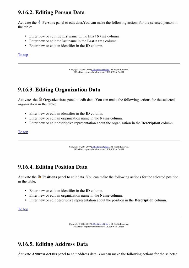
9.16.2. Editing Person Data
Activate the Persons panel to edit data.You can make the following actions for the selected person in the table:
• Enter new or edit the first name in the First Name column. • Enter new or edit the last name in the Last name column. • Enter new or edit an identifier in the ID column.
To top
Copyright © 2006-2009 LKSoftWare GmbH. All Rights Reserved.JSDAI is a registered trade mark of LKSoftWare GmbH.
9.16.3. Editing Organization Data
Activate the Organizations panel to edit data. You can make the following actions for the selected organization in the table:
• Enter new or edit an identifier in the ID column. • Enter new or edit an organization name in the Name column. • Enter new or edit descriptive representation about the organization in the Description column.
To top
Copyright © 2006-2009 LKSoftWare GmbH. All Rights Reserved.JSDAI is a registered trade mark of LKSoftWare GmbH.
9.16.4. Editing Position Data
Activate the Positions panel to edit data. You can make the following actions for the selected position in the table:
• Enter new or edit an identifier in the ID column. • Enter new or edit an organization name in the Name column. • Enter new or edit descriptive representation about the position in the Description column.
To top
Copyright © 2006-2009 LKSoftWare GmbH. All Rights Reserved.JSDAI is a registered trade mark of LKSoftWare GmbH.
9.16.5. Editing Address DataActivate Address details panel to edit address data. You can make the following actions for the selected
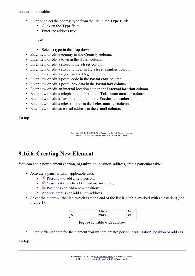
address in the table:
• Enter or select the address type from the list in the Type filed: • Click on the Type field. • Enter the address type.
Or
• Select a type in the drop down list.• Enter new or edit a country in the Country column.• Enter new or edit a town in the Town column. • Enter new or edit a street in the Street column, • Enter new or edit a street number in the Street number column. • Enter new or edit a region in the Region column. • Enter new or edit a postal code in the Postal code column. • Enter new or edit a postal box data in the Postal box column. • Enter new or edit an internal location data in the Internal location column. • Enter new or edit a telephone number in the Telephone number column. • Enter new or edit a facsimile number in the Facsimile number column.• Enter new or edit a telex number in the Telex number column.• Enter new or edit an e-mail address in the e-mail column.
To top
Copyright © 2006-2009 LKSoftWare GmbH. All Rights Reserved.JSDAI is a registered trade mark of LKSoftWare GmbH.
9.16.6. Creating New ElementYou can add a new element (person, organization, position, address) into a particular table:
• Activate a panel with an applicable data: • Persons - to add a new person; • Organizations - to add a new organization; • Positions - to add a new position; • Address details - to add a new address.
• Select the autorow (the line, which is at the end of the list in a table, marked with an asterisk) (see Figure 1).
Figure 1. Table with autorow
• Enter particular data for the element you want to create: person, organization, position or address.
To top
Copyright © 2006-2009 LKSoftWare GmbH. All Rights Reserved.JSDAI is a registered trade mark of LKSoftWare GmbH.

9.16.7. Copying and Pasting
You can copy and paste organizations, persons or positions in the Persons and Organizations window. You can copy elements in the tables, from a table to the Organizations tree, from the tree to table and in the Organizations tree:
• Copy Paste Person • Copy Paste Organization • Copy Paste Position
Copy Paste Person
Follow the routine to copy and paste a person:
• In the table of the Persons panel. • Activate the Persons panel. • Right click on an applicable person in the table list. A context sensitive menu appears (see
Figure 1). • Select Copy Person menu item.
Figure 1. Context sensitive menu in Persons panel, Copy Person
• Right click on the auto row (cell with an asterisk) at the bottom of the table list. A context sensitive menu appears (Figure 2).
• Select Paste Person menu item.
Figure 2. Context sensitive menu in Persons panel, Paste Person
• From the table in the Persons tabbed panel to the Organizations tree: • Right click on an applicable person in the table list. • Select Copy Person menu item. • Right click on an applicable organization node in the Organizations tree. • Select Paste menu item.
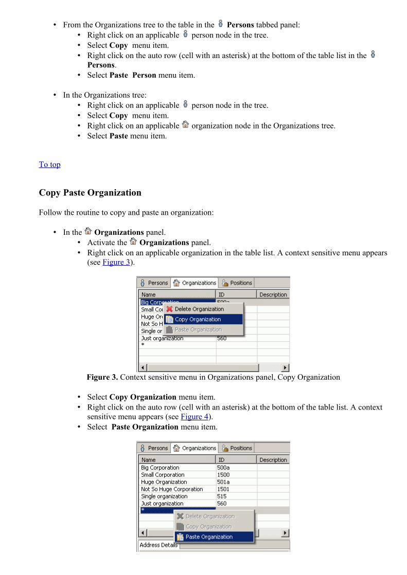
• From the Organizations tree to the table in the Persons tabbed panel: • Right click on an applicable person node in the tree. • Select Copy menu item. • Right click on the auto row (cell with an asterisk) at the bottom of the table list in the
Persons. • Select Paste Person menu item.
• In the Organizations tree: • Right click on an applicable person node in the tree. • Select Copy menu item. • Right click on an applicable organization node in the Organizations tree. • Select Paste menu item.
To top
Copy Paste Organization
Follow the routine to copy and paste an organization:
• In the Organizations panel. • Activate the Organizations panel. • Right click on an applicable organization in the table list. A context sensitive menu appears
(see Figure 3).
Figure 3. Context sensitive menu in Organizations panel, Copy Organization
• Select Copy Organization menu item. • Right click on the auto row (cell with an asterisk) at the bottom of the table list. A context
sensitive menu appears (see Figure 4).• Select Paste Organization menu item.
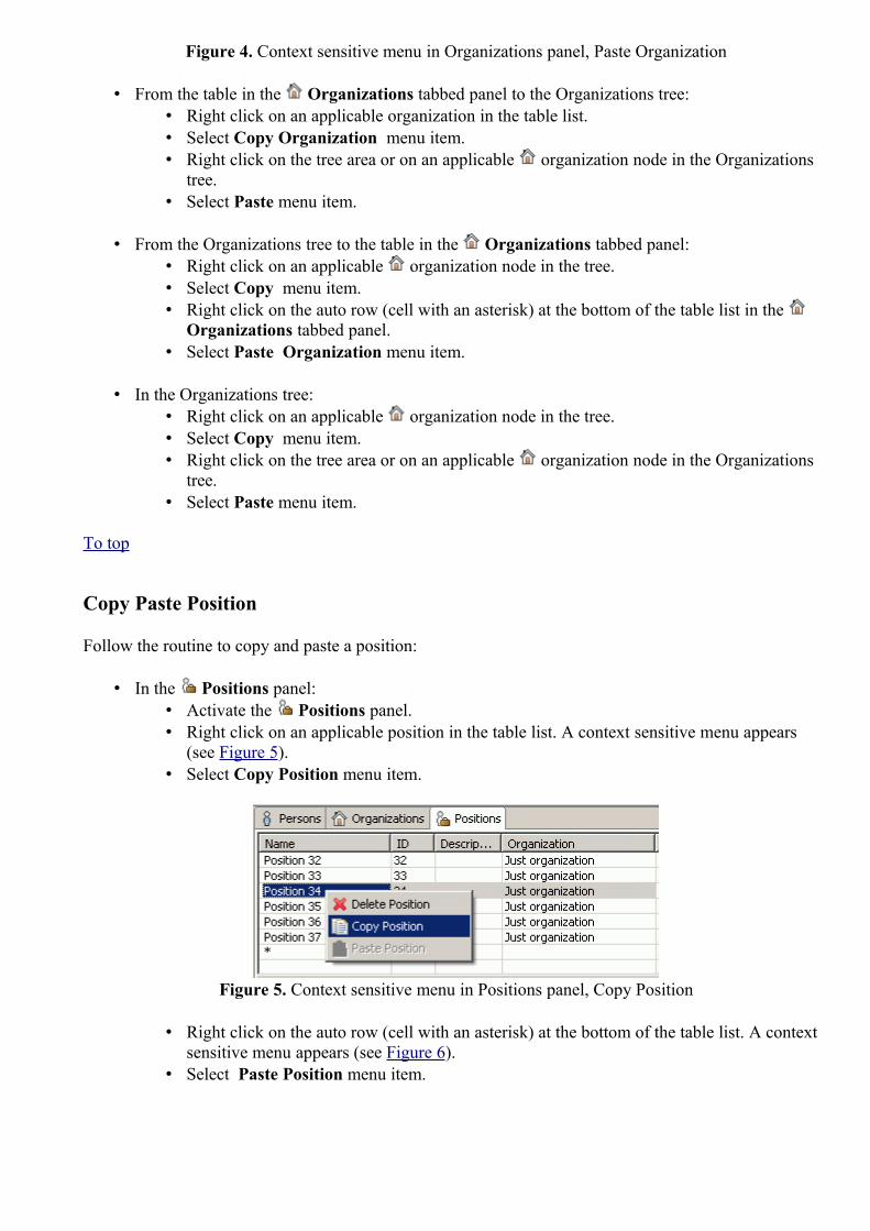
Figure 4. Context sensitive menu in Organizations panel, Paste Organization
• From the table in the Organizations tabbed panel to the Organizations tree: • Right click on an applicable organization in the table list. • Select Copy Organization menu item. • Right click on the tree area or on an applicable organization node in the Organizations
tree. • Select Paste menu item.
• From the Organizations tree to the table in the Organizations tabbed panel: • Right click on an applicable organization node in the tree. • Select Copy menu item. • Right click on the auto row (cell with an asterisk) at the bottom of the table list in the
Organizations tabbed panel. • Select Paste Organization menu item.
• In the Organizations tree: • Right click on an applicable organization node in the tree. • Select Copy menu item. • Right click on the tree area or on an applicable organization node in the Organizations
tree. • Select Paste menu item.
To top
Copy Paste Position
Follow the routine to copy and paste a position:
• In the Positions panel: • Activate the Positions panel. • Right click on an applicable position in the table list. A context sensitive menu appears
(see Figure 5). • Select Copy Position menu item.
Figure 5. Context sensitive menu in Positions panel, Copy Position
• Right click on the auto row (cell with an asterisk) at the bottom of the table list. A context sensitive menu appears (see Figure 6).
• Select Paste Position menu item.

Figure 6. Context sensitive menu in Positions panel, Paste Position
• From the table in the Positions tabbed panel to the Organizations tree: • Right click on an applicable position in the table list. • Select Copy Position menu item. • Right click on an applicable organization node in the Organizations tree. • Select Paste menu item.
• From the Organizations tree to the table in the Positions tabbed panel: • Right click on an applicable position node in the tree. • Select Copy menu item. • Right click on the auto row (cell with an asterisk) at the bottom of the table list in the
Positions tabbed panel. • Select Paste Position menu item.
• In the Organizations tree: • Right click on an applicable position node in the tree. • Select Copy menu item. • Right click on the tree area or on an applicable organization node in the Organizations
tree. • Select Paste menu item.
To top
Copyright © 2006-2009 LKSoftWare GmbH. All Rights Reserved.JSDAI is a registered trade mark of LKSoftWare GmbH.
9.16.8. Deleting
You can delete redundant or incorrect elements from the dataset in the Persons and Organizations window (table list and tree):
• Delete Person • Delete Organization • Delete Position
Delete Person
Follow the routine to delete a person

• From the table list: • Activate Persons panel. • Right click on the person, you want to delete, in the table list. A context sensitive menu
appears (see Figure 1). • Select Delete Person menu item.
Figure 1. Context sensitive menu, Delete Person
• From the Organizations tree: • Right click on a person node in the organizations tree on the left side of the window. • Select Delete menu item.
To top
Delete Organization
Follow the routine to delete an organization
• From the table list: • Activate Organizations panel: • Click on the tab on the right side of the window. • Right click on the organization, you want to delete, in the table list. A context sensitive
menu appears (see Figure 2). • Select Delete Organization menu item.
Figure 2. Context sensitive menu, Delete Organization
• From the Organizations tree: • Right click on a organization node in the organizations tree on the left side of the
window. • Select Delete menu item.
To top

Delete Position
Follow the routine to delete a position
• From the table list: • Activate Positions panel: • Click on the tab on the right side of the window. • Right click on the position, you want to delete, in the table list. A context sensitive
menu appears (see Figure 3). • Select Delete Position menu item.
Figure 3. Context sensitive menu, Delete Position
• From the Organizations tree: • Right click on a position node in the organizations tree on the left side of the window. • Select Delete menu item.
To top
Copyright © 2006-2009 LKSoftWare GmbH. All Rights Reserved.JSDAI is a registered trade mark of LKSoftWare GmbH.
9.16.9. Moving Element
The following movings can be performed by dragging and dropping in the Persons and Organizations window:
• Moving of the selected table element into the organizations tree ; • Moving of nodes in the organizations tree .
Moving Table Element into Tree
Follow the routine to move the table element into the organizations tree:
• Click on an applicable element in a particular tabbed panel: • Persons - to select a person; • Organizations - to select an organization; • Positions - to select a position.
• Drag and drop the element onto the destination node in the organizations tree. The destination node is highlighted on the tree (see Figure 1).

Or
• The same result can be achieved by copying and pasting the selected element.
Figure 1. Position 'Position1' is dragged onto 'F&F corporation' node in the treeTo top
Moving Tree Nodes
You can change an organization hierarchy, by moving nodes into applicable positions:
• Click on the node in the organizations tree. • Drag and drop it in the desired destination place.
Or
• The same result can be achieved by cutting and pasting the selected element.
You can move an applicable organization, a person or a position onto the desired organization node in a hierarchy.
To top
Copyright © 2006-2009 LKSoftWare GmbH. All Rights Reserved.JSDAI is a registered trade mark of LKSoftWare GmbH.
9.16.10. Removing from OrganizationThere is a possibility to remove an element (sub-organization, person or position) from an organization hierarchy:
• Right click on an element node you want to remove ( sub-organization, person or position). A context sensitive menu appears (see Figure 1).
• Select Remove from Organization menu item.

Figure 1. Context sensitive menu, Remove from organization
• The selected element is removed from the organizations hierarchy, but it is still present in the table list of a particular panel ( Organizations, Persons or Positions).
To top
Copyright © 2006-2009 LKSoftWare GmbH. All Rights Reserved.JSDAI is a registered trade mark of LKSoftWare GmbH.
9.17.1. Products ViewA Product as individual records the identification of an existing or potential future artefact - an actual product whose properties can only be known by observation or by derivation from observations.The Products view presents a list of product as individual instances together with assigned properties in the table list (see Figure 1). The default column perspective contains the following columns:
• Id - specifies an identifier of the product as individual version.• Name - specifies the word or group of words by which the product as individual is referred to. • Description - specifies additional information about the product as individual.• Design - specifies a part, which is the design of the product as individual.• In Service Date - specifies a date, when the product as individual was started to use.• Out of Service Date - specifies the expiration date of the product as individual.
Figure 1. Products view (default columns)
To top

Copyright © 2008-2009 LKSoftWare GmbH. All Rights Reserved.JSDAI is a registered trade mark of LKSoftWare GmbH.
9.17.2. Creating Product
Follow the routine to create a new product as individual element in the Products view table list (see Figure 1).
Figure 1. Products view table with highlighted auto row
• Select the auto row in the table (see Figure 1 highlighted cell in the Id column). • Enter an identifier of the new product as individual element. • Press Enter key. A new product as individual element appears in the Products view table (see
Figure 2).
Figure 2. Created product as individual element (highlighted)To top
Copyright © 2009 LKSoftWare GmbH. All Rights Reserved.JSDAI is a registered trade mark of LKSoftWare GmbH.
9.17.3. Editing Product Data
Activate the Products view. Select an applicable product as individual element in the table list. You can edit the following:
• Enter a new or edit the current product as individual identifier in the Id column. • Enter the text, which defines the product as individual name into the Name column. • Enter additional information about the product as individual in the Description column. • The Design column contains the link to a part, which is a design of the current product as
individual. The value of this column can be changed only by copying and pasting a particular

part element form the Part Classification view (if available). • Enter a new date by typing value or select it from the pop up table in the In Service Date column. • Enter a new date by typing value or select it from the pop up table in the Out of Service Date
column.
To top
Copyright © 2009 LKSoftWare GmbH. All Rights Reserved.JSDAI is a registered trade mark of LKSoftWare GmbH.
9.17.4. Removing Product
Activate the Products view. Follow the routine to remove a particular product as individual element form the table:
• Select a product as individual element in the table list. • Right click on the Id column. • Select the Delete menu item in the appeared context sensitive menu.
The selected product as individual element is removed from the Products view table list.
To top
Copyright © 2008-2009 LKSoftWare GmbH. All Rights Reserved.JSDAI is a registered trade mark of LKSoftWare GmbH.
9.18.1. States ViewA State is the mode of being in which something does or could exist or existed for a period of time. The States view presents a hierarchy of assemblies/ components with the applied states (see Figure 1). The state of the parent assembly may contain a sub state, which is the state of the child assembly component (see Figure 1 - State 1 is a state of the parent assembly and State 2 is a state of the child assembly component).The default column perspective contain the following columns:
• Name - presents a hierarchy of assemblies/ components with the applied states. • Description - specifies the word or group of words by which the state is referred to. • State type - the purpose of the association of the state with a product.

Figure 1. States view (default columns)
To top
Copyright © 2008-2009 LKSoftWare GmbH. All Rights Reserved.JSDAI is a registered trade mark of LKSoftWare GmbH.
9.18.2. Creating State
Follow the routine to create a new state for the selected element in the States view:
• Right click on an applicable element ( assembly or assembly component). • Select the New state menu item in the appeared context sensitive menu (see Figure 1).
Figure 1. Context sensitive menu with selected New state menu item
A new node named 'New state' appears under the selected element (see Figure 2).

Figure 2. Created new state
To top
Copyright © 2008-2009 LKSoftWare GmbH. All Rights Reserved.JSDAI is a registered trade mark of LKSoftWare GmbH.
9.18.3. Adding Sub State
Follow the routine to add a sub state for the parent state:
• First of all there should exist a tree of assembly components with their own states (see Figure 1).
Figure 1. The tree with assembly components with their own states (State 1 and State 2)
• Select a lower level state in the tree (e.g. 'State 2' in Figure 1). • Drag it and drop on the higher level state (e.g. 'State 1' in Figure 1). The lower level state
becomes a sub state of the higher level state (see Figure 2).

Figure 2. Sub state (selected)
To top
Copyright © 2008-2009 LKSoftWare GmbH. All Rights Reserved.JSDAI is a registered trade mark of LKSoftWare GmbH.
9.18.4. Editing State Data
Activate the States view. Select an applicable state in the table list. You can edit the following:
• Enter the text, which defines the state name into the Name column. • Enter additional information about the state in the Description column. • Enter a new value or select predefined value from the combo box in the State type column.
To top
Copyright © 2008-2009 LKSoftWare GmbH. All Rights Reserved.JSDAI is a registered trade mark of LKSoftWare GmbH.
9.18.5. Removing
Activate the States view. Follow the routine to remove an applicable element form the tree table:
• Select an element ( assembly/ part/ state) in the tree table. • Right click on the Name column. • Select the Delete menu item in the appeared context sensitive menu.
The selected element is removed from the States view tree table.To top
Copyright © 2008-2009 LKSoftWare GmbH. All Rights Reserved.JSDAI is a registered trade mark of LKSoftWare GmbH.

9.19.1. Stratum Technologies View
The Stratum technologies view (available by selecting in the main menu bar Window -> Show view -> Other then under PCB Layer Stack node) presents a list of stratum technologies (see Figure 1). The first column presents the row element - stratum technology, other columns contain data of the particular stratum technology. The default column perspective contain the following columns:
• Name -specifies the word or group of words by which the stratum technology is referred to. • Purpose - specifies the purpose of the current stratum technology. The predefined values are:
build-up material, coating, core material, embedded passive capacitor dielectric, embedded passive resistor, generic layer, glue, gluemask, lands only, pastemask, power or ground, signal, silkscreen, soldermask or solderpaste.
• Thickness - specifies the stratum technology stratum thickness for a layer. • Min feature - specifies the stratum technology minimum finished feature size for a layer. • Min Spacing - specifies the stratum technology minimum finished feature spacing for a layer.• Material - specifies the stratum technology material designation.• Electrical conductivity - specifies the stratum technology conductivity classification for material
identification for a layer.
Figure 1. Stratum technologies viewTo top
Copyright © 2008-2009 LKSoftWare GmbH. All Rights Reserved.JSDAI is a registered trade mark of LKSoftWare GmbH.
9.19.2. Creating Stratum Technology
Follow the routine to create a new stratum technology in the Stratums Technologies view tree table (see Figure 1):

Figure 1. Stratum Technologies view (with highlighted autorow)
• Select the auto row in the table (see Figure 1 highlighted cell in the Name column). • Click on the selected auto row to enter in to the edit mode. • Enter a name for the new stratum technology. • Press Enter key. A new record appears in the Stratum Technologies view tree table (see
Figure 2). The Purpose column is filled with default value, which you can change by selecting a new value from the list.
Figure 2. Created new stratum technology element (highlighted)
To top
Copyright © 2008-2009 LKSoftWare GmbH. All Rights Reserved.JSDAI is a registered trade mark of LKSoftWare GmbH.
9.19.3. Editing Stratum Technology Data
Activate the Stratum Technologies view. Select an applicable stratum technology element in the tree table. You can edit the following:
• Enter a new or edit the current value in the Name column. • Select another value in a combo box of the Purpose column. You can not enter a new value, just
select an existing one.• Enter a thickness value into the Thickness column. You can also select a new tolerance value
or/and change units. • Enter a value of the minimum finished feature size into the Min Feature column. You can also
change units by selecting a new unit from the combo box. • Enter a value of the minimum finished feature spacing into the Min Spacing column. The units

can be changed by selecting an applicable value in the drop down list. • Select or enter a new value of a material designation into the Material column. • Select an applicable value of the electrical conductivity classification in the Electrical
conductivity column. The selected value is associated to the current material designation, presented in the Material column.
To top
Copyright © 2008-2009 LKSoftWare GmbH. All Rights Reserved.JSDAI is a registered trade mark of LKSoftWare GmbH.
9.20.1. Stratums View
The Stratums view (available by selecting in the main menu bar Window -> Show view -> Other then under PCB Layer Stack node) presents a tree table with a hierarchy of layers, referenced by a particular design stack model, which is identified in the top section of the Stratums view window (see Figure 1). Note: The data appears in the Stratums view only after an applicable design stack model is selected in the Design Stack Models view.The default perspective contains the following columns:
• Name - specifies the word or group of words by which the layer is referred to. • # - specifies the stratum technology occurrence number for the layer. The value depend on the
selected Purpose of the layer.• Based on - specifies the base of stratum technology occurrence for the layer. The possible values
are: down, independent and up.• Macro - specifies the stratum technology occurrence definition for the layer. • Purpose - specifies the purpose of the current layer. The predefined values are: build-up material,
coating, core material, embedded passive capacitor dielectric, embedded passive resistor, generic layer, glue, gluemask, lands only, pastemask, power or ground, signal, silkscreen, soldermask and solderpaste.
• Thickness - specifies the stratum technology stratum thickness for the layer.• Min feature - specifies the stratum technology minimum finished feature size for the layer.• Max feature - specifies the stratum technology maximum feature size requirement for the layer.• Min Spacing - specifies the stratum technology minimum finished feature spacing for the layer.• Electrical conductivity - specifies the stratum technology conductivity classification for material
identification for the layer.
Figure 1. Stratums view
To top

Copyright © 2008-2009 LKSoftWare GmbH. All Rights Reserved.JSDAI is a registered trade mark of LKSoftWare GmbH.
9.20.2. Stratums hierarchy
The Name column in the Stratums view tree table presents the hierarchy of layers (see Figure 1):
• Root node - the layer or sequential group name. • Second and lower level nodes - layers or sequent elements grouped into particular sequential
group.
Figure 1. Stratums hierarchy
To top
Copyright © 2008-2009 LKSoftWare GmbH. All Rights Reserved.JSDAI is a registered trade mark of LKSoftWare GmbH.
9.20.3. Creating Layer
Follow the routine to create a new layer in the Stratums hierarchy (see Figure 1):
Figure 1. Stratums view, hierarchy of layers with highlighted autorow
• Select an autorow (highlighted node in Figure 1). • Click on the selected autorow to enter into the edit mode. • Enter a name for a new layer. • Press Enter key.
If you want to include a new layer into a particular sequential group:

• Right click on a sequential group node. • Select the Insert element menu item in the context sensitive menu (see Figure 2).
Figure 2. Context sensitive menu, selected Insert element menu item
• The autorow appears under the selected sequential group node. Follow the previously described steps to create a new layer.
The created layer node appears in the Startums tree table.
To top
Copyright © 2008-2009 LKSoftWare GmbH. All Rights Reserved.JSDAI is a registered trade mark of LKSoftWare GmbH.
9.20.4. Creating Sequential Group
There are several possibilities to add a new sequential group in the Stratums hierarchy:
• Add sequential group before the selected element (layer, sequential group) ;• Add sequential group after the selected element (layer, sequential group) ; • Insert sequential group as a child for the selected sequential group .
Add sequence before
Follow the routine to add a sequential group before the selected element:
• Select a layer or a sequential group node in the tree table. • Right click and select the Add sequence before menu item in the appeared context sensitive menu
(see Figure 1). • A new node, named 'New group' appears before the selected element node.

Figure 1. Context sensitive menu with selected Add sequence before menu itemTo top
Add sequence after
Follow the routine to add a sequential group after the selected element:
• Select a layer or a sequential group node int the tree table. • Right click and select the Add sequence after menu item in the appeared context sensitive menu
(see Figure 2 ). • A new node, named 'New group' appears after the selected element node.
Figure 2. Context sensitive menu with selected Add sequence after menu itemTo top
Insert sequence
Follow the routine to insert a new sequential group under the selected sequential group node:
• Select a sequential group node in the table tree. • Right click and select the Insert sequence menu item in the appeared context sensitive menu (see
Figure 3). • A new node, named 'New group' appears beneath the selected sequence group node.

Figure 3. Context sensitive menu with selected Insert sequence menu itemTo top
Copyright © 2006-2009 LKSoftWare GmbH. All Rights Reserved.JSDAI is a registered trade mark of LKSoftWare GmbH.
9.20.5. Changing Layer Location
Follow the routine to change the selected layer position in the Stratums hierarchy:
• Select an applicable element (layer or sequential group of layers) node in the table tree. • Drag the selected node and drop it in the desired destination place. The possible destination place
is marked with the horizontal line (see Figure 1). • The selected object appears in the selected destination place.
Figure 1. Selected layer is dragged to the destination place, which is marked as horizontal lineTo top
Copyright © 2008-2009 LKSoftWare GmbH. All Rights Reserved.JSDAI is a registered trade mark of LKSoftWare GmbH.
9.20.6. Moving Autorow to RootAfter inserting an element into a sequential group, the autorow remains under the sequential group node
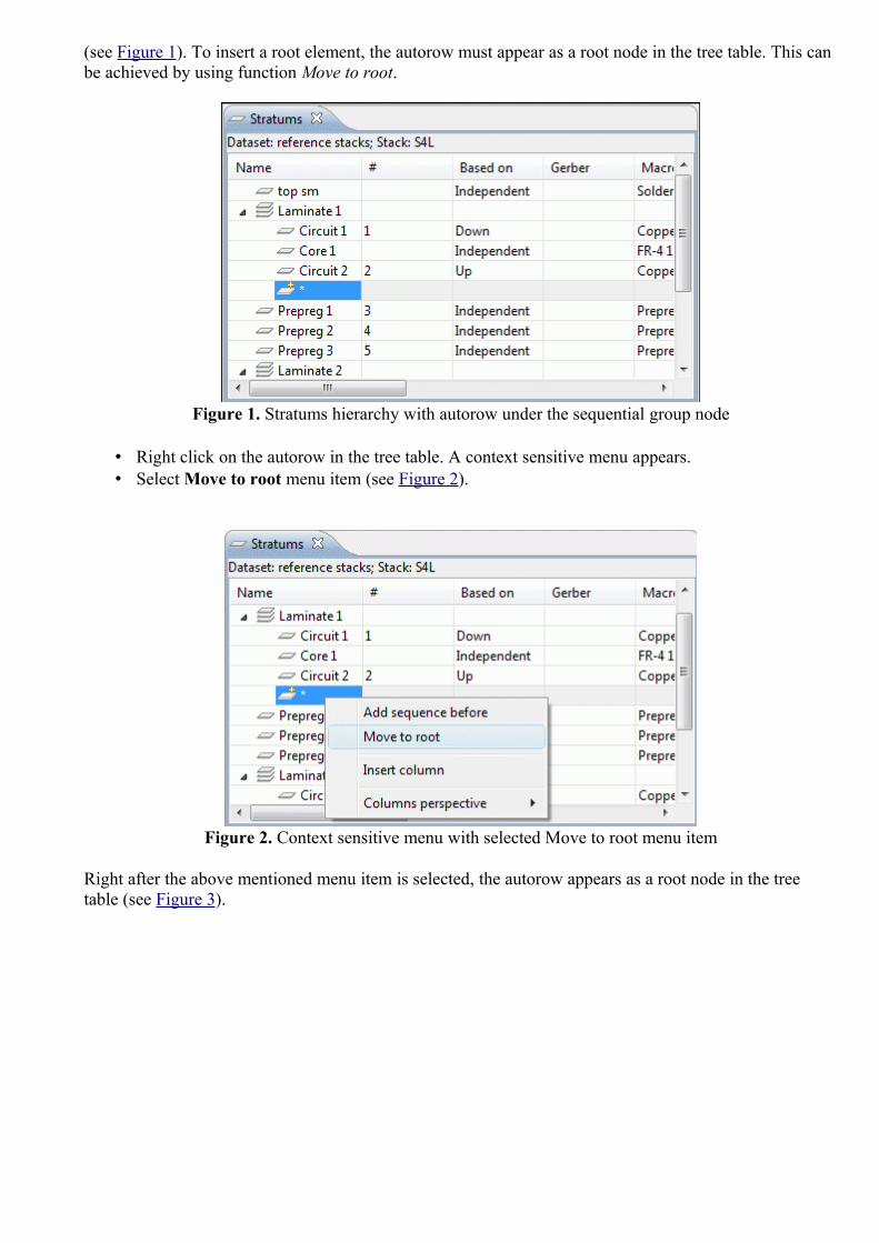
(see Figure 1). To insert a root element, the autorow must appear as a root node in the tree table. This can be achieved by using function Move to root.
Figure 1. Stratums hierarchy with autorow under the sequential group node
• Right click on the autorow in the tree table. A context sensitive menu appears. • Select Move to root menu item (see Figure 2).
Figure 2. Context sensitive menu with selected Move to root menu item
Right after the above mentioned menu item is selected, the autorow appears as a root node in the tree table (see Figure 3).

Figure 3. Autorow as root node in the tree table
To top
Copyright © 2008-2009 LKSoftWare GmbH. All Rights Reserved.JSDAI is a registered trade mark of LKSoftWare GmbH.
9.20.7. Editing Layer Data
Activate the Stratums view. Select and applicable layer in the tree table. You can edit the following:
• Enter the text, which defines the layer name into the Name column.• Select the value of the base of stratum technology occurrence for the layer in the Based on column
r/o combo box.• Select the stratum technology occurrence definition in the Macro column combo box. Also you
can enter a new value into this field. A new stratum technology element will be created.
Note. If you select an existing value (coming from Stratum Technologies view) in the Macro combo box, then some columns are filled with data automatically.
• Select the purpose for the layer in the Purpose column r/o combo box.• Enter the thickness value of the current layer into the Thickness column.• Enter the stratum technology minimum finished feature size value for the layer into the Min
feature column.• Enter the stratum technology maximum feature size requirement value for the layer into the Max
feature column.• Enter the stratum technology minimum finished feature spacing value for the layer Min spacing
column.• Select an applicable electrical conductivity value in the Electrical conductivity column r/o combo
box.
To top
Copyright © 2008-2009 LKSoftWare GmbH. All Rights Reserved.JSDAI is a registered trade mark of LKSoftWare GmbH.

9.21.1. Stratums Cross-section View
The Stratums Cross-section view (available by selecting in the main menu bar Window -> Show view -> Other then under PCB Layer Stack node) presents the visual 2D presentation of objects, defined in Stratums and Passages views for the particular design stack model, selected in the Design Stack Models view (see Figure 1). The referenced design stack model is identified in the top section of the view window. The layers and passages are presented on the left side of the view window.
Figure 1. Stratums cross-section view
The Stratums Cross-section view has it's own tool bar on the top right corner of the page.Button icon Description
Toggle Collapsed/Exploded view
Open menu to select color schema
To top
Menu
There is a possibility to change the color schema for the stratums cross-section view by using Click on the button on the top right corner of the Stratums Cross-section view window.
To top
Copyright © 2008-2009 LKSoftWare GmbH. All Rights Reserved.JSDAI is a registered trade mark of LKSoftWare GmbH.
9.21.2. Toggling Collapsed/Exploded View
By default the objects in the Stratums Cross-section View are presented in exploded view - each

layer is presented separately (see Figure 1).
Figure 1. Stratums Cross-section exploded view
To toggle the collapsed view (see Figure 2) click on the Toggle Collapsed/Exploded view button in the tool bar.
Figure 2. Stratums Cross-section collapsed viewTo top
Copyright © 2008-2009 LKSoftWare GmbH. All Rights Reserved.JSDAI is a registered trade mark of LKSoftWare GmbH.
9.21.3. Changing Color Schema
There is a possibility to change the color of components, text and background for in the Stratums cross-section view. To change the color schema directly in the Stratums Cross-section view click on the button on the top right corner of the Stratums Cross-section view window. The following schemas are available by default: Default (see Figure 1), Red highlighting (see Figure 2), Darklighting (see Figure 3) and Greyscale (see Figure 4). The default colors for each available schema are set in the Color Schemas preferences (select in the main menu Window -> Preferences -> Stratums Cross-section -> Color Schemas). A new color schema can be created in the Color Schemas preferences page.
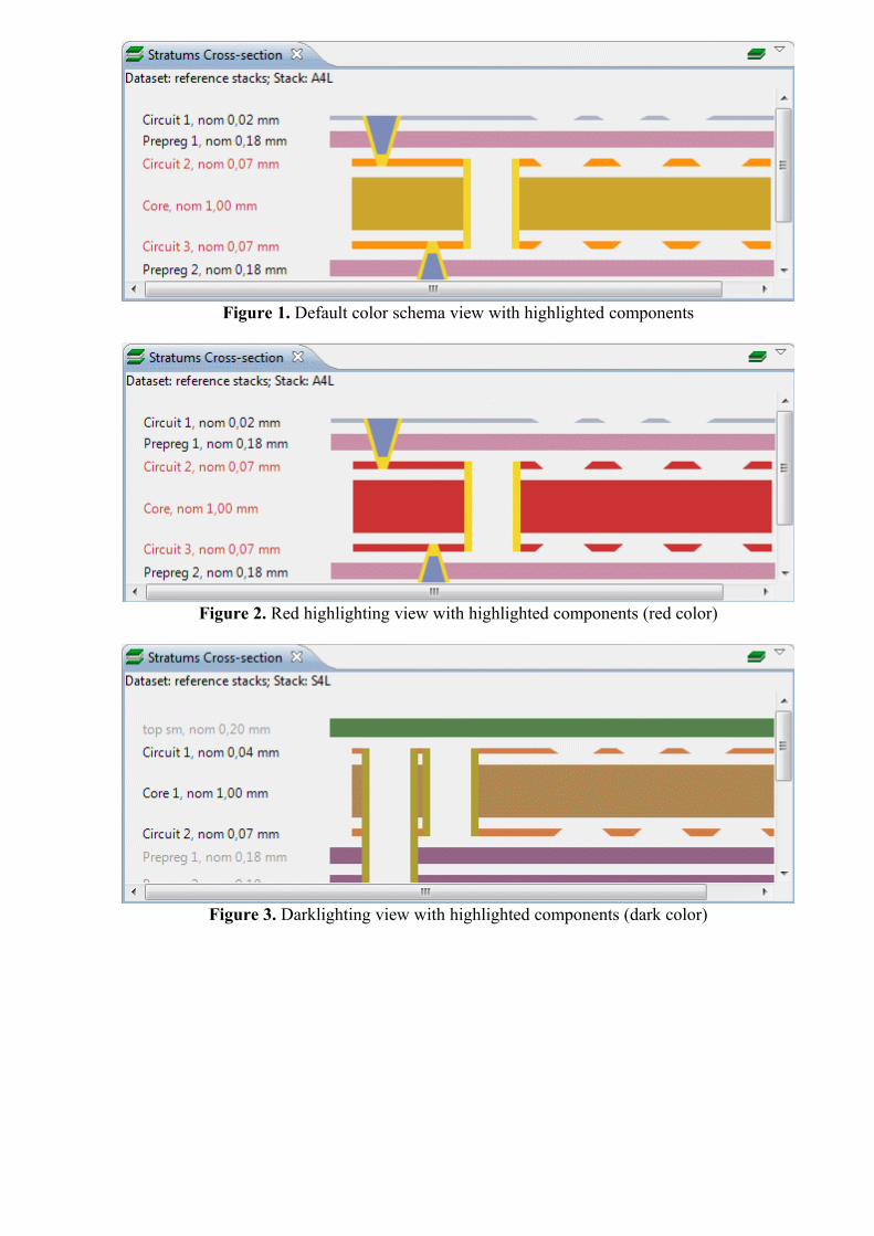
Figure 1. Default color schema view with highlighted components
Figure 2. Red highlighting view with highlighted components (red color)
Figure 3. Darklighting view with highlighted components (dark color)

Figure 4. Greyscale view with highlighted components (black color)
To top
Copyright © 2008-2009 LKSoftWare GmbH. All Rights Reserved.JSDAI is a registered trade mark of LKSoftWare GmbH.
9.21.4. Highlighting Components
You can highlight an applicable layer or a group of layers or a passage in the Stratums Corss-section view (see Figure 1). A name and a thickness parameters of the selected layer are highlighted together a 2D presentation.
Figure 1. Stratums Cross-section view with highlighted group of layers (red color)
To top
Highlighting layer or group of layers
Follow the routine to highlight an applicable layer or group of layers in the Stratums Corss-section view:
• Activate the Stratums view on the screen. • Click on an applicable layer or group of layer row in the tree table. • The particular layer or group of layers is highlighted in the Stratums Cross-section view (see
Figure 2 and Figure 3).

Figure 2. Stratums view with selected layer and Startums Cross-section view with the highlighted layer
Figure 3. Stratums view with selected sequential group of layers and Startums Cross-section view with the highlighted layers
To top
Highlighting passage
Follow the routine to highlight an applicable passage in the Stratums Corss-section view:
• Activate the Passages view on the screen. • Click on an applicable passage row in the tree table. • The particular passage is highlighted in the Stratums Cross-section view (see Figure 4).

Figure 4. Stratums view with selected passage and Startums Cross-section view with the highlighted passage (red color)
To top
Copyright © 2008-2009 LKSoftWare GmbH. All Rights Reserved.JSDAI is a registered trade mark of LKSoftWare GmbH.
9.22.1. TasksA task represents data that specifies task methods, that is the method specified for a particular activity. The task method is the combination of something to be achieved and , optionally, a way to achieve it. The same result can be achieved through more than one method. A task method can be defined as simple text or as a processible structure using repeats, sequences and decision points. A task method can be associated with the resources required to do it.
The Tasks window presents a tree table with a task hierarchy, which is available for the selected dataset (see Figure 1).
Figure 1. Tasks windowTo top

Copyright © 2006-2009 LKSoftWare GmbH. All Rights Reserved.JSDAI is a registered trade mark of LKSoftWare GmbH.
9.22.2. Task Hierarchy
The Task column in the Tasks window presents the hierarchy of tasks (see Figure 1):
• Root nodes - tasks, that are independent from each other. • Second and further level nodes (branches and leaves) - sub tasks, which have be performed in a
particular order. The next task can be started only after the previous one was finished.
Figure 1. Task hierarchy
To top
Copyright © 2006-2009 LKSoftWare GmbH. All Rights Reserved.JSDAI is a registered trade mark of LKSoftWare GmbH.
9.22.3. Editing Task Data
Activate a Tasks window to edit data. Select a task you want to edit in a task hierarchy. You can perform the following editing actions:
• Enter the text, which defines the task name into the Task column. • Enter the text into the Description column. • Assign zonal breakdown in the Location column. • Assign role or position in the Role/Position column. • Assign the referenced task in the Task Invocation column. • Select the documents to be associated with the selected task by using the Browse button in the
Assigned documents column. • <...TBD ...> in the Risk column. • Assign auxiliary materials in the Auxiliary materials column. • Enter the value and select the unit from the combo box in the Duration column. • Assign tools in the Tools column. • Enter the value and select the unit from the combo box in the Adjustment column. • Assign product or part in the Product/Part column.
To top

Copyright © 2006-2009 LKSoftWare GmbH. All Rights Reserved.JSDAI is a registered trade mark of LKSoftWare GmbH.
9.22.4. Creating Task
• Creating Top Level Task • Creating Task Element
• Add Task Before • Add Task After
There is a possibility to create a new task in a Task hierarchy.
Creating Top Level Task
You can create a new top level task by using the autorow:
• Ensure that the autorow is in the right position - the last row in the tree table, if it is not - drag and drop it at the end of the tree table.
• Enter data into the autorow. • Press Enter key. The new task is created as the root node in the tree.
To top
Creating Task Element
You can add an element for a created task:
• Drag and drop the autorow onto the preferable task.
Or
• Right click on a parent task and select Add child menu item in the appeared context sensitive menu.
• Enter data into the autorow. • Press Enter key. The new task is added.
Note. The task will be added at the end of the tree branch list (the same level node).You can add a task into particular position - before or after the selected task
Adding Task Before
Follow the routine to add a task before the selected task:
• Drag and drop the autorow into an applicable position.
Or
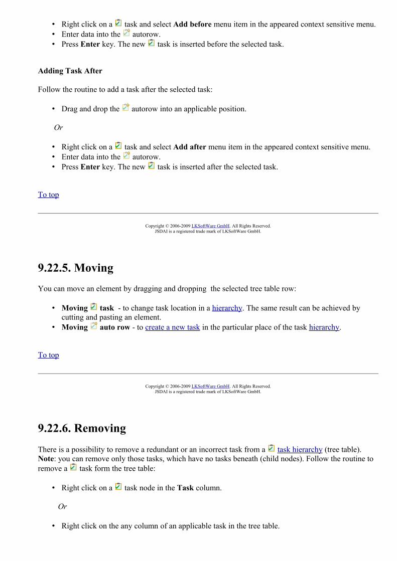
• Right click on a task and select Add before menu item in the appeared context sensitive menu. • Enter data into the autorow. • Press Enter key. The new task is inserted before the selected task.
Adding Task After
Follow the routine to add a task after the selected task:
• Drag and drop the autorow into an applicable position.
Or
• Right click on a task and select Add after menu item in the appeared context sensitive menu. • Enter data into the autorow. • Press Enter key. The new task is inserted after the selected task.
To top
Copyright © 2006-2009 LKSoftWare GmbH. All Rights Reserved.JSDAI is a registered trade mark of LKSoftWare GmbH.
9.22.5. Moving You can move an element by dragging and dropping the selected tree table row:
• Moving task - to change task location in a hierarchy. The same result can be achieved by cutting and pasting an element.
• Moving auto row - to create a new task in the particular place of the task hierarchy.
To top
Copyright © 2006-2009 LKSoftWare GmbH. All Rights Reserved.JSDAI is a registered trade mark of LKSoftWare GmbH.
9.22.6. Removing
There is a possibility to remove a redundant or an incorrect task from a task hierarchy (tree table). Note: you can remove only those tasks, which have no tasks beneath (child nodes). Follow the routine to remove a task form the tree table:
• Right click on a task node in the Task column.
Or
• Right click on the any column of an applicable task in the tree table.

• The context sensitive menu appears. • Select Erase task menu item.
To top
Copyright © 2006-2009 LKSoftWare GmbH. All Rights Reserved.JSDAI is a registered trade mark of LKSoftWare GmbH.
9.22.7. Assigning Task Invocation
There can exist some leaf tasks, which are of the same performance as one of the root tasks in a task hierarchy. To avoid repetition of information, those top level tasks may be referenced by leaf tasks. You can reference a task from the separate Tasks window, if it is opened in the TDE window.Note: You can reference only the top (root) level task. Also you can assign a referenced task only for the task, which is a leaf element. After a task becomes an invocation task, it can not be assigned as a child element to other tasks.Follow the routine to assign the selected top level task to a leaf task:
• Click on the top (root) level task in a task hierarchy. The selected task is highlighted.• Drag the selected task onto the Task Invocation column of an applicable leaf task. A
transparent icon and name of the top level task appears while dragging (see Figure 1).
Figure 1. Top level task 'Task 4' dragged to leaf task 'Task 3.1'
• Release the mouse button when you have the selected task in the desired location. The task you've selected is moved to the Task Invocation column (see Figure 2).
Figure 2. Top level task 'Task 4' assigned to leaf task 'Task 3.1'
You can remove the assigned task from the Task Invocation column:
• Right click on the referenced task name in the Task Invocation column. The context sensitive menu appears.

• Select Delete menu item. The task disappears from the cell.
To top
Copyright © 2006-2009 LKSoftWare GmbH. All Rights Reserved.JSDAI is a registered trade mark of LKSoftWare GmbH.
9.22.8. Assigning Zonal Breakdown
You can set a zonal breakdown for the selected task in the Location column:
• Ensure that Tasks and Zonal Breakdowns windows are opened (see Figure 1).
Figure 1. Tasks and Zonal Breakdowns windows in the TDE
• Click on an applicable zonal breakdown in the Zonal Breakdowns window. The selected zonal breakdown is highlighted.
• Drag the selected zonal breakdown onto the Location column of an applicable task in the Tasks window. A transparent icon and name of the zonal breakdown appears while dragging (see Figure 2).
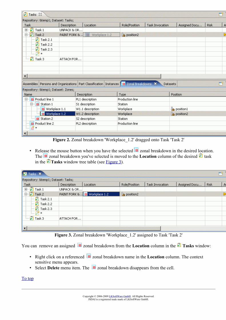
Figure 2. Zonal breakdown 'Workplace_1.2' dragged onto Task 'Task 2'
• Release the mouse button when you have the selected zonal breakdown in the desired location. The zonal breakdown you've selected is moved to the Location column of the desired task in the Tasks window tree table (see Figure 3).
Figure 3. Zonal breakdown 'Workplace_1.2' assigned to Task 'Task 2'
You can remove an assigned zonal breakdown from the Location column in the Tasks window:
• Right click on a referenced zonal breakdown name in the Location column. The context sensitive menu appears.
• Select Delete menu item. The zonal breakdown disappears from the cell.
To top
Copyright © 2006-2009 LKSoftWare GmbH. All Rights Reserved.JSDAI is a registered trade mark of LKSoftWare GmbH.

9.22.9. Assigning Part
You can set a part for the selected task in the Product/Part column:
• Ensure that Tasks and Part Details windows are opened (see Figure 1).
Figure 1. Tasks and Part Details window in TDE
• Click on an applicable object in the Part Details window. The selected object is highlighted. • Drag the selected object onto the Product/Part column of an applicable task in the Tasks
window. A transparent icon and name of the selected object appears while dragging (see Figure 2).
Figure 2. Selected part dragged onto task
• Release the mouse button when you have the selected object in the desired location. The object
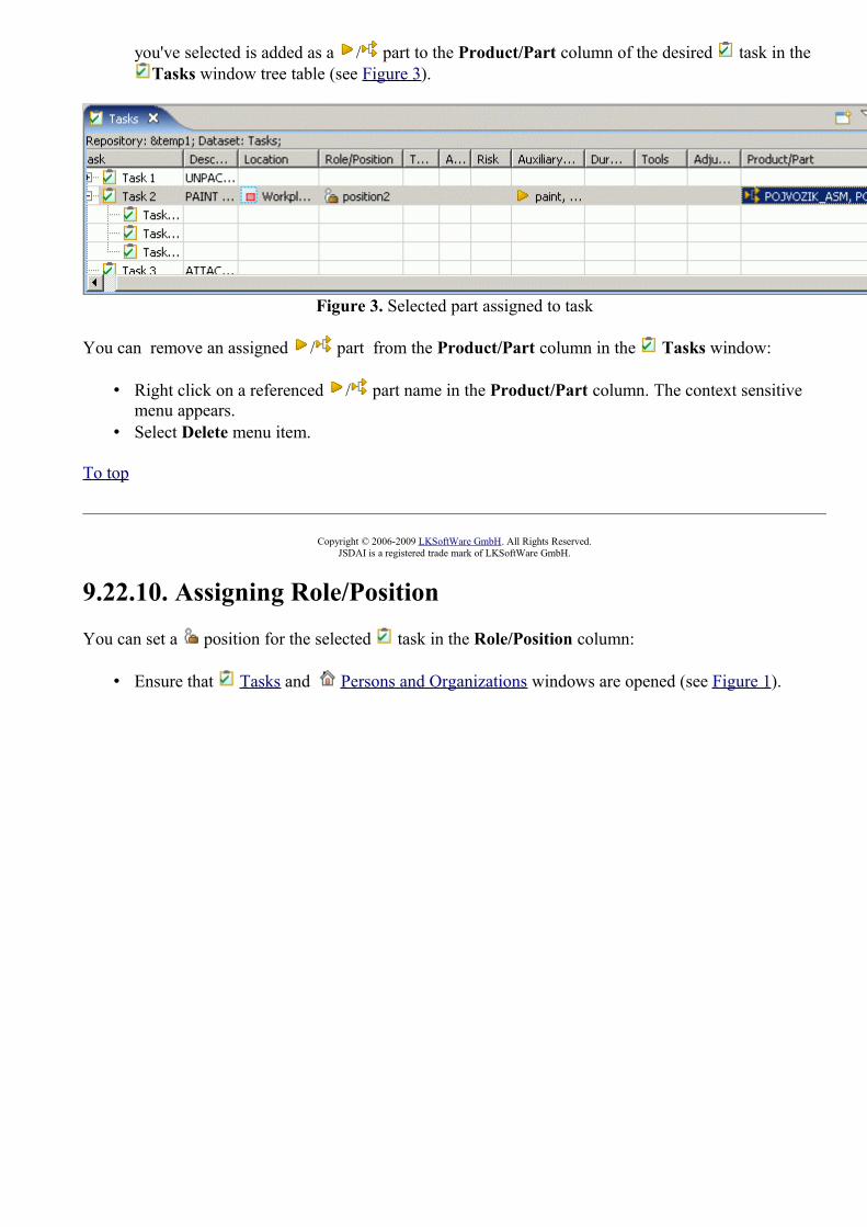
you've selected is added as a / part to the Product/Part column of the desired task in the Tasks window tree table (see Figure 3).
Figure 3. Selected part assigned to task
You can remove an assigned / part from the Product/Part column in the Tasks window:
• Right click on a referenced / part name in the Product/Part column. The context sensitive menu appears.
• Select Delete menu item.
To top
Copyright © 2006-2009 LKSoftWare GmbH. All Rights Reserved.JSDAI is a registered trade mark of LKSoftWare GmbH.
9.22.10. Assigning Role/Position
You can set a position for the selected task in the Role/Position column:
• Ensure that Tasks and Persons and Organizations windows are opened (see Figure 1).

Figure 1. Tasks and Persons and Organizations windows in TDE
• Click on an applicable position in the organizations tree (on the left side of the Persons and Organizations window) or in a table of the Positions tabbed panel (on the right of the Persons and Organizations window). The selected object is highlighted in the tree and in the table list (see Figure 1).
• Drag the selected object onto the Role/Position column of an applicable task in the Tasks window. A transparent icon and name of the selected object appears while dragging (see Figure 2).

Figure 2. Selected position dragged onto task
• Release the mouse button when you have the selected object in the desired location. The object you've selected is added to the Role/Position column of the desired task in the Tasks window tree table (see Figure 3).
Figure 3. Selected position assigned to task
You can remove an assigned position from the Role/Position column in the Tasks window:
• Right click on a referenced position name in the Role/Position column. The context sensitive menu appears.
• Select Delete menu item.
To top
Copyright © 2006-2009 LKSoftWare GmbH. All Rights Reserved.JSDAI is a registered trade mark of LKSoftWare GmbH.

9.22.11. Assigning Auxiliary Materials
You can set an auxiliary material for the selected task in the Auxiliary Materials column:
• Ensure that Tasks and Parts Classification windows are opened (see Figure 1).
Figure 1. Task and Parts Classification windows in TDE
• Click on an applicable part in the table (on the right side of the Parts Classification window), which should be added as an auxiliary material for the selected task. The selected object is highlighted in the table list (see Figure 1).
• Drag the selected object onto the Auxiliary Materials column of an applicable task in the Tasks window. A transparent icon and name of the selected object appear while dragging (see Figure 2).
Figure 2. Selected part dragged onto task
• Release the mouse button when you have the selected object in the desired location. The object

you've selected is added to the Auxiliary Materials column in the Tasks window tree table (see Figure 3).
Figure 3. Selected auxiliary material assigned to taskYou can remove the assigned auxiliary material from the Auxiliary Materials column in the Tasks window:
• Right click on an auxiliary material name in the Auxiliary Materials column. The context sensitive menu appears.
• Select Delete menu item.
To top
Copyright © 2006-2009 LKSoftWare GmbH. All Rights Reserved.JSDAI is a registered trade mark of LKSoftWare GmbH.
9.22.12. Assigning Tools
You can set a tool for the selected task in the Tools column:
• Ensure that Tasks and Parts Classification windows are opened (see Figure 1).

Figure 1. Task and Parts Classification window on the workbench
• Click on an applicable part in the table (on the right of the Parts Classification window), which should be added as a tool for the selected task. The selected object is highlighted in the tree or in the table list (see Figure 1).
• Drag the selected object onto the Tools column of an applicable task in the Tasks window. A transparent icon and name of the selected object appears while dragging (see Figure 2).
Figure 2. Selected part dragged onto task
• Release the mouse button when you have the selected object in the desired location. The object you've selected is added to the Auxiliary Materials column of the desired task in the Tasks window tree table (see Figure 3).
Figure 3. Selected auxiliary material assigned to taskYou can remove an assigned tools from the Tools column in the Tasks window:
• Right click on a referenced tool name in the Tools column. The context sensitive menu appears.
• Select Delete menu item.
To top
Copyright © 2006-2009 LKSoftWare GmbH. All Rights Reserved.JSDAI is a registered trade mark of LKSoftWare GmbH.

9.23.1. Zonal BreakdownsA zonal breakdown is a partitioning of a product into a set of related zonal elements to support engineering, analysis and other activities that may be performed in relation to the product.The Zonal Breakdown Editor presents a tree table with a zonal breakdown hierarchy, which is available for the selected dataset (see Figure 1):
• Name - hierarchy of zonal breakdowns;• Id - zonal breakdown identifier;• Type - zonal breakdown type definition;• Role/Position - associated position.
Figure 1. Zonal Breakdown windowTo top
Copyright © 2006 LKSoftWare GmbH. All Rights Reserved.JSDAI is a registered trade mark of LKSoftWare GmbH.
9.23.2. Zonal Breakdown Hierarchy
The Name column in the Zonal Breakdown window presents a hierarchy of zonal breakdowns (see Figure 1):
• Root nodes - zonal breakdowns, that are independent from each other. The order of those zonal breakdowns is not important, but you can change order by dragging an applicable zonal breakdown row and dropping it at a desired place (if editing is available).
• Second and further level nodes (branches and leaves) - sub-zonal breakdowns.
Figure 1. Zonal breakdown hierarchy
To top
Copyright © 2006 LKSoftWare GmbH. All Rights Reserved.JSDAI is a registered trade mark of LKSoftWare GmbH.

9.23.3. Creating Zonal Breakdown
• Creating Top Level Zonal Breakdown • Creating Zonal Breakdown Element
There is a possibility to add a new zonal breakdowns to a Zonal Breakdown hierarchy.
Creating Top Level Zonal Breakdown
You can add a new top level zonal breakdown by using the autorow:
• Ensure that the autorow is in the right position - the last row in the tree table, if it is not - drag and drop it at the end of the tree table.
• Enter data into the autorow. • Press Enter key. A new zonal breakdown is created as the root node in the tree.
To top
Creating Zonal Breakdown Element
You can add an element for the already created zonal breakdown:
• Drag and drop the autorow onto the preferable zonal breakdown.
Or
• Right click on a parent zonal breakdown and select Add element menu item in the appeared context sensitive menu.
• Enter data into the autorow. • Press Enter key. A new zonal breakdown is added.
Note. A zonal breakdown will be added at the end of the tree branch (the same level node).
To top
Copyright © 2006-2009 LKSoftWare GmbH. All Rights Reserved.JSDAI is a registered trade mark of LKSoftWare GmbH.
9.23.4. Editing Zonal Breakdown Data
Activate the Zonal Breakdowns view to edit data. Select the zonal breakdown you want to edit in a zonal breakdown hierarchy. You can edit the following:
• Enter the text, which defines the zonal breakdown name into the Name column. • Enter the identifier into the Id column.

• Select a type of the zonal breakdown in the Type column: • Double click on the cell to set the editing mode ON. The combo box arrow appears. • Click on the arrow to view the drop down list. • Select an applicable value.
Or
• Enter an applicable value into the text field.• Assign a position in the Position column (see Assigning Position).
To top
Copyright © 2006-2009 LKSoftWare GmbH. All Rights Reserved.JSDAI is a registered trade mark of LKSoftWare GmbH.
9.23.5. Assigning Position
You can set a position for the selected zonal breakdown in the Position column:
• Ensure that Zonal Breakdowns and Persons and Organizations views are opened (see Figure 1).
Figure 1. Zonal Breakdowns and Persons and Organizations views in TDE
• Click on an applicable position in the organizations tree (on the left side of the Persons and Organizations view) or in a table of the Positions tabbed panel (on the right of the Persons and Organizations view). The selected object is highlighted in the tree or in the table list (see Figure 1).

• Drag the selected object onto the Position column of an applicable zonal breakdown in the Zonal Breakdowns view. A transparent icon and name of the selected object appears while dragging.
• Release the mouse button when you have the selected object in the desired location. The object you've selected is added to the Position column of the desired zonal breakdown in the Zonal Breakdowns view tree table (see Figure 2).
Figure 2. Selected position assigned to zonal breakdown
You can remove an assigned position from the Position column in the Zonal Breakdowns view:
• Right click on a referenced position name in the Position column. The context sensitive menu appears.
• Select Delete menu item.
To top
Copyright © 2006-2009 LKSoftWare GmbH. All Rights Reserved.JSDAI is a registered trade mark of LKSoftWare GmbH.
9.23.6. Moving You can move an element by dragging and dropping the selected tree table row:
• Moving zonal breakdown - to change a zonal breakdown location in the hierarchy. The same result can be achieved by cutting and pasting an element.
• Moving autorow - to create a new zonal breakdown in a particular place of a zonal breakdown hierarchy.
To top
Copyright © 2006-2009 LKSoftWare GmbH. All Rights Reserved.JSDAI is a registered trade mark of LKSoftWare GmbH.
9.23.7. Removing
There is a possibility to remove a redundant or an incorrect zonal breakdown from a zonal breakdown hierarchy (tree table). Note, you can remove only those zonal breakdowns, which have no zonal breakdowns beneath (child nodes). Follow the routine to remove a zonal breakdown form the

tree table:
• Right click on a zonal breakdown node. The context sensitive menu appears. • Select Erase zone menu item.
To top
Copyright © 2006-2009 LKSoftWare GmbH. All Rights Reserved.JSDAI is a registered trade mark of LKSoftWare GmbH.
10.1. Customizing Views
IDA-STEP provides capabilities to customize the views, which display structured data. The Parts, Part Details and other views in IDA-STEP display data by using tables or tree-tables. The layout of tables is predefined and the data types they display are set. The most right column in the tree table is marked with an asterisk (*). In case the column cell is empty, no additional data is available for the row element. In other case, a user can review a list of available data, which are not currently included into the tree table, by pressing on the asterisk. The Other data window appears on the screen with the list of available data together with assigned values. The presenting data can be included into the tree table simply by double clicking on an applicable data type and filling required fields in the appeared Insert column wizard dialog window.
The user has full control on the columns in tables - add, remove or configure. When a column is added, the user can define its content by choosing from the predefined data types or use a wizard to specify custom data types using templates.
To top
Copyright © 2007-2009 LKSoftWare GmbH. All Rights Reserved.JSDAI is a registered trade mark of LKSoftWare GmbH.
10.2. Inserting ColumnFollow the routine to insert a new column into the table of the currently active view:
• Right click on the table area - on the element/row. • Select the Insert column menu item in the appeared context sensitive menu. • The Insert column wizard window appears on the screen. Use the wizard to create an applicable
column.• The created column appears in the table.
Or
• Press with a mouse button on the most right column cell with an asterisk. The Other data window appears with available additional data (see Figure 1). Note. If you are in a view, which can be linked with other views, the Other data window can show up only for a short time. To vanish this inconvenience switch Off the Link with views button.

Figure 1. Other data window
• Select an applicable data type in the list and double click on it. • The Insert column wizard dialog window appears on the screen.
By default the Column from data radio button is selected and the previously selected data type is highlighted in the wizard page. You can select another radio button to create new data or press Finish button to include already associated data to the tree table.
To top
Copyright © 2007-2009 LKSoftWare GmbH. All Rights Reserved.JSDAI is a registered trade mark of LKSoftWare GmbH.
10.3. Removing ColumnFollow the routine to remove a redundant column from the table:
• Open an applicable view in the workbench. • Right click on the column you want to remove. • Select the Remove column menu item in the appeared context sensitive menu. • The selected column disappears from the table.
Note. If the removed column contained some data, the type identification and column value can be found in the most right column (labeled '*') of the tree table. To get a list of available columns, which are not currently located in the table, press on the * and examine the appeared Other data window.
To top
Copyright © 2007-2009 LKSoftWare GmbH. All Rights Reserved.JSDAI is a registered trade mark of LKSoftWare GmbH.
10.4. Configuring ColumnYou can configure already created dynamic column:
• Right click on the column you want to configure. A context sensitive menu appears. • Select the Configure Column menu item. The Configure dynamic column wizard dialog
window appears (see Figure 1). The current column parameters are presented in the wizard dialog window.

• You can change a role and a template after the Simple column radio button is selected (see Simple column in Insert column wizard).
Or
• Compose new templates for the column after the Compose column radio button is selected (see Compose column in Insert column wizard).
• Specify new parameters for the column and click Finish button.
Figure 1. Configure column wizard dialog window
To top
Copyright © 2007-2009 LKSoftWare GmbH. All Rights Reserved.JSDAI is a registered trade mark of LKSoftWare GmbH.
10.5. Insert Column WizardThe Insert Column wizard helps the user to add an applicable column to the selected view table (Figure 1). This wizard can be invoked by selecting Insert column menu item in the context sensitive menu or by clicking on a particular element in Other data window list.A new column may be created in three ways, by selecting a particular radio button:
• Column from data - a new column is created with already associated data. • Simple column - a new column is created, by specifying the element object, column type and
other criteria. • Composite column - a new column is composed by the user.

Figure 1. Insert column wizard page
Column from data
After the Column from data radio button is selected, a new wizard page appears on the screen (see Figure 2):
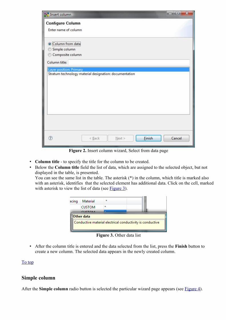
Figure 2. Insert column wizard, Select from data page
• Column title - to specify the title for the column to be created. • Below the Column title field the list of data, which are assigned to the selected object, but not
displayed in the table, is presented. You can see the same list in the table. The asterisk (*) in the column, which title is marked also with an asterisk, identifies that the selected element has additional data. Click on the cell, marked with asterisk to view the list of data (see Figure 3).
Figure 3. Other data list
• After the column title is entered and the data selected from the list, press the Finish button to create a new column. The selected data appears in the newly created column.
To top
Simple column
After the Simple column radio button is selected the particular wizard page appears (see Figure 4).

Figure 4. Wizard page to create a new dynamic column
• Select an object, the column to be related to from the Choose role drop down list. There are presented available objects of the selected view in the drop down list.
• Choose column type by selecting a particular radio button in the Choose column type layout. The list of types is specific for each view.
• Click Next button. • The second page appears, which depends on what selection was made in the previous page. • Enter needed data and click Finish button to create a new dynamic column.
To top
Composite column
After the Composite column radio button is selected, a new wizard page appears on the screen (see Figure 5).

Figure 5. Wizard page to composite new column
• Column title - to specify the title for the column to be created. • The table in the middle section of the page contains a list of column templates. There can be
applied several templates for one column.• Role column specifies a role of the element. • Template column specifies a type of the column to be created.
• Add Template button - create a new template for the column. After this button is pressed a new wizard dialog page appears on the screen (see Figure 6) to choose a role and a template for the column to be created.

Figure 6. Wizard page to choose data role and template for the column
If there are additional parameters for the selected template, press Next button to go to the next wizard page (see Figure 7). After all needed parameters are entered/selected, press Finish button. The created template appears in the table list (wizard page in Figure 5).
Figure 7. Wizard page to select additional parameters for the column to be created
• Remove Template button - remove the selected template from the table. • Edit Template button - edit a particular template after it is selected in the table.
To top
Copyright © 2007-2009 LKSoftWare GmbH. All Rights Reserved.JSDAI is a registered trade mark of LKSoftWare GmbH.
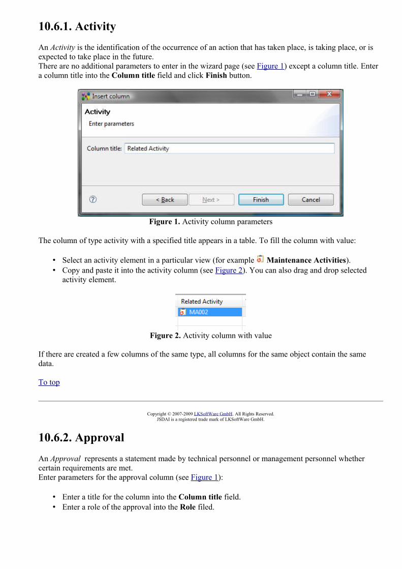
10.6.1. ActivityAn Activity is the identification of the occurrence of an action that has taken place, is taking place, or is expected to take place in the future. There are no additional parameters to enter in the wizard page (see Figure 1) except a column title. Enter a column title into the Column title field and click Finish button.
Figure 1. Activity column parameters
The column of type activity with a specified title appears in a table. To fill the column with value:
• Select an activity element in a particular view (for example Maintenance Activities). • Copy and paste it into the activity column (see Figure 2). You can also drag and drop selected
activity element.
Figure 2. Activity column with value
If there are created a few columns of the same type, all columns for the same object contain the same data.
To top
Copyright © 2007-2009 LKSoftWare GmbH. All Rights Reserved.JSDAI is a registered trade mark of LKSoftWare GmbH.
10.6.2. ApprovalAn Approval represents a statement made by technical personnel or management personnel whether certain requirements are met. Enter parameters for the approval column (see Figure 1):
• Enter a title for the column into the Column title field. • Enter a role of the approval into the Role filed.

Figure 1. Approval parameters
• After all needed parameters are entered, click Finish button to create a column. The column of type approval appears in the table.
Follow the routine to fill an approval column:
• Double click on an approval column cell. The Approval dialog window appears on the screen (see Figure 2):
Figure 2. Approval dialog window
• Enter an applicable value into the Purpose field or select the predefined value from the drop down list:
• disposition - the referenced object is approved for series production; • equipment order - the referenced object has reached a status in which changes are
subject to a defined change process and tools and other equipment required for production may be ordered;
• planning - the referenced object is technically complete and has reached a status sufficiently stable so that other designs may be based on it.
• Enter an applicable value into the Status field or select the predefined value from the drop down list:
• approved - the required authorizations have been obtained for a particular role of approval for a piece of product data;

• disapproved - the required authorizations have been denied for a particular role of approval for a piece of product data;
• not yet approved - the required authorizations have not been obtained for a particular role of approval for a piece of product data.
• Select an organization in the Person organization drop down list or use the button next to the field to get the whole list of available organizations.
• Enter a date of approval or use the button next to the field to get the pop up calendar.
Note. There may be created some columns with the different title and the same role. Data, entered into one of the approval columns, are displayed in all columns with the same role.
To top
Copyright © 2007-2009 LKSoftWare GmbH. All Rights Reserved.JSDAI is a registered trade mark of LKSoftWare GmbH.
10.6.3. Assembly Component DefinitionThe Assembly component definition is a definition of a component, i.e. the part, which is instantiated as a component in an assembly.There are no additional parameters to enter in the wizard page (see Figure 1) except a column title. Enter a column title into the Column title field and click Finish button.
Figure 1. Assembly component definition column parameters
The column of type assembly component definition with a specified title appears in a table. To fill the column with value or edit the existing one:
• Select an applicable value from the drop down list.Or
• Double click on the cell. • The Select entity page appears on the screen (see Figure 2) to select an applicable definition to be
associated with the selected assembly component.• Press OK button after the selection is made.

Figure 2. Select entity page with a list of available definitions
The selected definition appears in the selected cell. The value of the cell is composed of some strings, separated by comma: product name, product id,version id,definition id.
To top
Copyright © 2009 LKSoftWare GmbH. All Rights Reserved.JSDAI is a registered trade mark of LKSoftWare GmbH.
10.6.4. CertificationA Certification is a documentation that asserts facts.Enter parameters for the certification column (see Figure 1):
• Enter a title for the column into the Column title field. • Enter a word or group of words by which the Certification is referred to into the Name filed.
Figure 1. Insert column wizard page to enter certification parameters
After all needed parameters are entered, click Finish button to create a column. The column of type approval appears in the table (see Figure 2).

Figure 2. Certification column
A certification column cell displays a name of the certification if one is present, or nothing - if the certification is not present. Follow the routine to fill a certification column with value:
• If a column cell is empty, click on the cell. The name of the certificate (entered while the certificate column creation) appears in the cell.
• The click on the cell with value removes the value from the cell.
Note. There may be created some columns with the different title and the same name. Data, entered into one of the certification columns, are displayed in all columns with the same name.
To top
Copyright © 2007-2009 LKSoftWare GmbH. All Rights Reserved.JSDAI is a registered trade mark of LKSoftWare GmbH.
10.6.5. ClassificationA Classification association associates a classification with an object.Enter the classification association parameters (see Figure 1):
• Enter a title for the column into the Column title field. • Enter the relationship value between classification and associated object.
Figure 1. Classification association parameters
• After all needed parameters are entered, click Finish button to create a column. The column of type classification is created (see Figure 2).
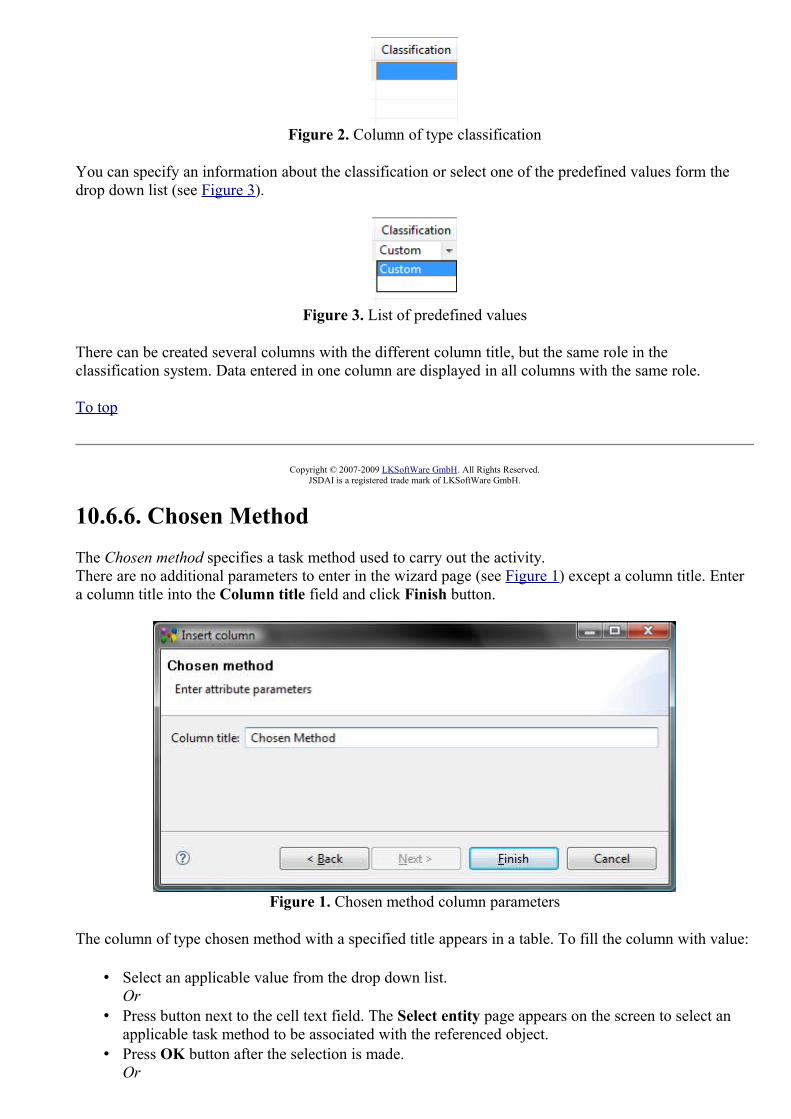
Figure 2. Column of type classification
You can specify an information about the classification or select one of the predefined values form the drop down list (see Figure 3).
Figure 3. List of predefined values
There can be created several columns with the different column title, but the same role in the classification system. Data entered in one column are displayed in all columns with the same role.
To top
Copyright © 2007-2009 LKSoftWare GmbH. All Rights Reserved.JSDAI is a registered trade mark of LKSoftWare GmbH.
10.6.6. Chosen MethodThe Chosen method specifies a task method used to carry out the activity.There are no additional parameters to enter in the wizard page (see Figure 1) except a column title. Enter a column title into the Column title field and click Finish button.
Figure 1. Chosen method column parameters
The column of type chosen method with a specified title appears in a table. To fill the column with value:
• Select an applicable value from the drop down list.Or
• Press button next to the cell text field. The Select entity page appears on the screen to select an applicable task method to be associated with the referenced object.
• Press OK button after the selection is made.Or
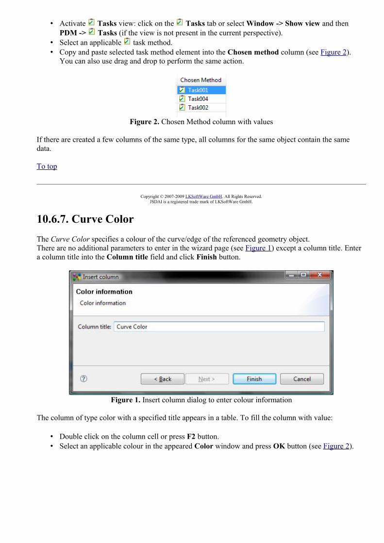
• Activate Tasks view: click on the Tasks tab or select Window -> Show view and then PDM -> Tasks (if the view is not present in the current perspective).
• Select an applicable task method. • Copy and paste selected task method element into the Chosen method column (see Figure 2).
You can also use drag and drop to perform the same action.
Figure 2. Chosen Method column with values
If there are created a few columns of the same type, all columns for the same object contain the same data.
To top
Copyright © 2007-2009 LKSoftWare GmbH. All Rights Reserved.JSDAI is a registered trade mark of LKSoftWare GmbH.
10.6.7. Curve ColorThe Curve Color specifies a colour of the curve/edge of the referenced geometry object.There are no additional parameters to enter in the wizard page (see Figure 1) except a column title. Enter a column title into the Column title field and click Finish button.
Figure 1. Insert column dialog to enter colour information
The column of type color with a specified title appears in a table. To fill the column with value:
• Double click on the column cell or press F2 button. • Select an applicable colour in the appeared Color window and press OK button (see Figure 2).

Figure 2. Color window to select colour
• The specified colour square appears in the selected column cell (see Figure 3).
Figure 3. Curve color column with specified colour
To top
Copyright © 2009 LKSoftWare GmbH. All Rights Reserved.DJSDAI is a registered trade mark of LKSoftWare GmbH.
10.6.8. DescriptionThe Description specifies additional information about the referenced object.Enter parameters of the description column (see Figure 1):
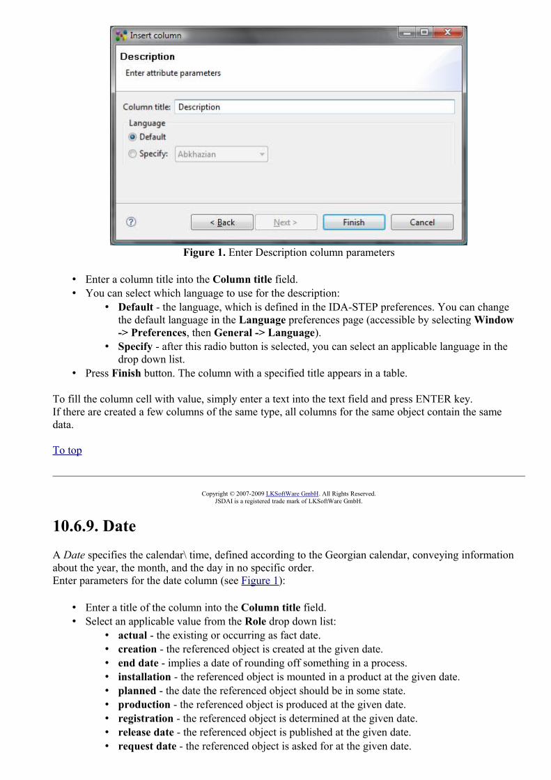
Figure 1. Enter Description column parameters
• Enter a column title into the Column title field. • You can select which language to use for the description:
• Default - the language, which is defined in the IDA-STEP preferences. You can change the default language in the Language preferences page (accessible by selecting Window -> Preferences, then General -> Language).
• Specify - after this radio button is selected, you can select an applicable language in the drop down list.
• Press Finish button. The column with a specified title appears in a table.
To fill the column cell with value, simply enter a text into the text field and press ENTER key.If there are created a few columns of the same type, all columns for the same object contain the same data.
To top
Copyright © 2007-2009 LKSoftWare GmbH. All Rights Reserved.JSDAI is a registered trade mark of LKSoftWare GmbH.
10.6.9. DateA Date specifies the calendar\ time, defined according to the Georgian calendar, conveying information about the year, the month, and the day in no specific order.Enter parameters for the date column (see Figure 1):
• Enter a title of the column into the Column title field. • Select an applicable value from the Role drop down list:
• actual - the existing or occurring as fact date.• creation - the referenced object is created at the given date.• end date - implies a date of rounding off something in a process.• installation - the referenced object is mounted in a product at the given date.• planned - the date the referenced object should be in some state.• production - the referenced object is produced at the given date.• registration - the referenced object is determined at the given date. • release date - the referenced object is published at the given date.• request date - the referenced object is asked for at the given date.

• signoff - the referenced object is withdrawn from some product, process and so on, at the given date.
• start date - the referenced object was included in some process at the given date.• update - the referenced object was altered at the given date.
Figure 1. Date parameters
• After all needed parameters are entered, press Finish button to create a column. The column of type date appears in the table (see Figure 2).
Figure 2. Column of type Date
To fill the column with value:
• Enter an applicable date value into the text box.
Or
• Click on the cell. • Click on the combo box arrow next to the text box. The calendar sheet appears (see Figure 3).
Figure 3. Calendar sheet to select an applicable date

• Select an applicable date from the sheet. • Press Enter key.
If there are created a few columns of the same type, all columns for the same object contain the same data.
To top
Copyright © 2007-2009 LKSoftWare GmbH. All Rights Reserved.JSDAI is a registered trade mark of LKSoftWare GmbH.
10.6.10. Date and TimeA Date and Time represents dates and times based on the Coordinated Universal Time.Enter parameters for the date column (see Figure 1):
• Enter a title of the column into the Column title field. • Select an applicable value from the Role drop down list:
• actual - the existing or occurring as fact date and time.• creation - the referenced object is created at the given date and time.• end date - implies a date and time of rounding off something in a process.• installation - the referenced object is mounted in a product at the given date and time.• planned - the date and time the referenced object should be in some state.• production - the referenced object is produced at the given date and time.• registration - the referenced object is determined at the given date and time. • release date - the referenced object is published at the given date and time.• request date - the referenced object is asked for at the given date and time.• signoff - the referenced object is withdrawn from some product, process and so on, at the
given date and time.• start date - the referenced object was included in some process at the given date and time.• update - the referenced object was altered at the given date and time.
Figure 1. Date and time parameters
• After all needed parameters are entered, click Finish button to create a column. The column of type date and time appears in the table.
To fill the column with value:

• Enter an applicable date value into the text box.
Or
• Click on the cell. • Click on the combo box arrow next to the text box. The date and time sheet appears (see Figure 2).
Figure 2. Date and time sheet
• Select an applicable date and time from the sheet. • Press Enter key.
If there are created a few columns of the same type, all columns for the same object contain the same data.
To top
Copyright © 2007-2009 LKSoftWare GmbH. All Rights Reserved.JSDAI is a registered trade mark of LKSoftWare GmbH.
10.6.11. DesignThe Design column specifies a part, which is a design for a particular product as individual.There are no additional parameters to enter in the wizard page (see Figure 1) except a column title. Enter a column title into the Column title field and click Finish button.

Figure 1. Design column parameters
The column of type design with a specified title appears in a table. To fill the column with value:
• Activate Part Details or Parts view. • Select an applicable element in one of the above mentioned views. • Drag and drop it on the Design column cell (see Figure 2).
Figure 2. Design column with values
If there are created a few columns of the same type, all columns for the same object contain the same data.
To top
Copyright © 2007-2009 LKSoftWare GmbH. All Rights Reserved.JSDAI is a registered trade mark of LKSoftWare GmbH.
10.6.12. DocumentA Document presents an association between a document and an object, where the assigned document provides information about the object it is associated to.Enter the document parameters (see Figure 1):
• Enter a title for the column into the Column title field. • Specify a role of the document to be associated with the selected object into the Document role
field.

Figure 1. Document parameters
• After all needed parameters are entered, click Finish button to create a column. The column of type document appears in the table (see Figure 2).
Figure 2. Column of type Document
To fill the column with value:
• Activate Documents view: click on the Documents tab or select Window -> Show view and then PDM -> Documents (if the view is not present in the current perspective).
• Select an applicable document, document version, file or file reference. • Copy and paste the selected element into the Document column. You can also use drag and drop
functionality to perform the same action.
There may be created some columns with the different title and the same document role. Data, entered into one of the document columns, are displayed in all columns with the same document role.
To top
Copyright © 2007-2009 LKSoftWare GmbH. All Rights Reserved.JSDAI is a registered trade mark of LKSoftWare GmbH.
10.6.13. ElementThe Element specifies a piece of product data that is under work. The element column content is a particular assembly component, which parent assembly is a design of the Subject.There are no additional parameters to enter in the wizard page (see Figure 1) except a column title. Enter a column title into the Column title field and click Finish button. The column with a specified title appears in a table.

Figure 1. Insert column dialog to enter parameters for element column
To fill the column cell with value:
• Select an element in the drop down list.
Or
• Use the button next to the field to get the whole list of available values. Select an applicable element and press OK button.
If there are created a few columns of the same type, all columns for the same object contain the same data.
To top
Copyright © 2009 LKSoftWare GmbH. All Rights Reserved.JSDAI is a registered trade mark of LKSoftWare GmbH.
10.6.14. External Data ExistsThe External Data Exists column indicates whether the external data is available for the referenced digital file or not.There are no additional parameters to enter in the wizard page (see Figure 1) except a column title. Enter a column title into the Column title field and click Finish button.
Figure 1. External data exists column parameters

The column cell is read only. The value 'Yes' in this column appears, only if the external data is available for the currently selected digital file.
To top
Copyright © 2007-2009 LKSoftWare GmbH. All Rights Reserved.JSDAI is a registered trade mark of LKSoftWare GmbH.
10.6.15. External file locationThe External file location specifies the location of a file in an external storage system. Enter parameters for the external file location column (see Figure 1):
• Enter a title for the column into the Column title field. • Specify a document location type in the Location type field or select one of the predefined values:
• URL - an absolute path of the external file in your file system or in the Internet, • filename - a name of the external file, • relative - a relative path of the external document.
• Press Finish button. The column with a specified title appears in the currently selected viewer table.
Figure 1. External file parameters
If the type of external location column is URL, the column cell is filled up automatically. Note: The value appears in the cell only if the file has an external file associated. You can change the location of the external file:
• Click with mouse on a column cell. The button appears next to the text field. • Press the button. The dialog appears to choose the target file. • Select an applicable file and press Open button. The path of the recently selected file appears in
the cell.
In other cases the value should be entered manually by typing the particular text into the text field of the column cell.
If there are created a few columns of the same type, all columns for the same object contain the same data.

To top
Copyright © 2007-2009 LKSoftWare GmbH. All Rights Reserved.JSDAI is a registered trade mark of LKSoftWare GmbH.
10.6.16. IdThe Id specifies an identifier of the referenced object. There are no additional parameters to enter in the wizard page (see Figure 1) except a column title. Enter a column title into the Column title field and click Finish button. The column with a specified title appears in a table.
Figure 1. Enter Id column parameters
To fill the column of type ID:
• Enter an identifier of the referenced object into text field. • Press Enter key.
If there are created a few columns of the same type, all columns for the same object contain the same data.
To top
Copyright © 2007-2009 LKSoftWare GmbH. All Rights Reserved.JSDAI is a registered trade mark of LKSoftWare GmbH.
10.6.17. MagnitudeThe Magnitude is a numerical quantitative measure associated to a referenced object.There are no additional parameters to enter in the wizard dialog page (see Figure 1), except a column title. Enter a column title into the Column title field and click Finish button.

Figure 1. insert column dialog to enter parameters for magnitude
The column cell is read only. The settings of quantities and units, which appear in the column, are defined in the Quantity and Units preferences (Window -> Preferences -> Numbers -> Quantities and Units).
To top
Copyright © 2009 LKSoftWare GmbH. All Rights Reserved.DJSDAI is a registered trade mark of LKSoftWare GmbH.
10.6.18. Material propertyThe Material property is a characteristic that depends on material aspects.Enter parameters for the material property column (see Figure 1):
• Enter a title for the column into the Column title field. • Select a conductivity classification to be associated with a material property from the Attribute
layout by selecting the particular radio button: • Electric conductivity - is a measure of a material's ability to conduct an electric current; • Thermal conductivity - is the property of a material that indicates its ability to conduct
heat; • Magnetic permeability - is the degree of magnetization of a material that responds
linearly to an applied magnetic field ; • Optical insertion loss - is the loss of signal power resulting from the insertion of a device
in an optical fiber; • Dielectric permittivity - is a physical quantity that describes how an electric field affects,
and is affected by a dielectric medium, and is determined by the ability of a material to polarize in response to the field, and thereby reduce the total electric field inside the material.

Figure 1. Enter parameters for material property column
• Click Finish button to create a column. The column of the specified type appears in the table. (see Figure 2).
Figure 2. Created column of type material property
The column contains the predefined list of values, which can be selected by the user. The values in the drop down list depend on the conductivity classification, selected in the wizard window:
• Electrical conductivity classification column contains the predefined values: conductive, non conductive, resistive, semi conductive and super conductive.
• Thermal conductivity classification column contains the predefined values: conductive, non conductive, resistive, semi conductive and super conductive.
• Magnetic permeability classification column contains the predefined values: free space permeability, low permeability, medium permeability and highly permeable.
• Optical insertion loss classification column contains the predefined values: vacuum, very low loss, low loss, medium loss and high loss.
• Dielectric permittivity classification column contains the predefined values: vacuum permittivity, low permittivity, medium permittivity and high permittivity.
There may be created some columns with the different title and the same conductivity classification. Data, entered into one of the material property columns, are displayed in all columns with the same conductivity classification.
To top
Copyright © 2007-2009 LKSoftWare GmbH. All Rights Reserved.JSDAI is a registered trade mark of LKSoftWare GmbH.

10.6.19. NameThe Name specifies the word or group of words by which an object is referred to. Enter parameters of the name column (see Figure 1):
Figure 1. Enter name column parameters
• Enter a column title into the Column title field. • You can select which language to use for the name:
• Default - the language, which is defined in the IDA-STEP preferences. You can change the default language in the Language preferences page (accessible by selecting Window -> Preferences, then General -> Language).
• Specify - after this radio button is selected, you can select an applicable language in the drop down list.
• Press Finish button. The column with a specified title appears in a table.
To fill the column cell with value, simply enter a text into the text field and press ENTER key.If there are created a few columns of the same type, all columns for the same object contain the same data.
To top
Copyright © 2007-2009 LKSoftWare GmbH. All Rights Reserved.JSDAI is a registered trade mark of LKSoftWare GmbH.
10.6.20. Network AssignmentThe Network assignment associates a network with a referenced terminal.There are no additional parameters to enter in the wizard page (see Figure 1) except a column title. Enter a column title into the Column title field and click Finish button.

Figure 1. Network assignment column parameters
The column of type network assignment with a specified title appears in a table. To fill the column with value or edit the existing one:
• Select an applicable value from the drop down list.Or
• Double click on the cell. • The Select entity page appears on the screen (see Figure 2) to select an applicable network to be
associated with the selected terminal.• Press OK button after the selection is made.
Figure 2. Select entity with the list of available networks
If there are created a few columns of the same type, all columns for the same object contain the same data.
To top
Copyright © 2009 LKSoftWare GmbH. All Rights Reserved.

JSDAI is a registered trade mark of LKSoftWare GmbH.
10.6.21. Person/OrganizationThe Person or organization associates a person or organization with the referenced object. Enter the person or organization assignment parameters (see Figure 1):
• Enter a title for the column into the Column title field. • Select a role of a person or organization from the Assignment role drop down list:
• alias scope - the alias of the referenced object is valid in the assigned person or organization;
• author - the referenced object has been created by the assigned person or organization. The author holds the copyright;
• classification officer - the assigned person or organization is formally responsible for the classification of the referenced object;
• concerned organization - the associated person or organization is interested in or affected by the referenced object;
• creator - the referenced object has been created by the assigned person or organization; • custodian - the assigned person or organization is responsible for the existence and
integrity of the referenced object; • customer - the assigned person or organization acts as a purchaser or consumer of the
referenced object; • design supplier - the assigned person or organization is the one who delivers the data
describing the referenced object; • editor - the assigned person or organization is responsible for making any changes to any
attribute of the referenced object; • id owner - the assigned person or organization is the one responsible for the designation of
an identifier; • location - the assigned organization is the place where the referenced object can be found
or where it takes place; • manufacturer - the assigned person or organization is the one who produces the actual
(physical) object; • notified person or organization - the person or organization that shall be informed about
the referenced object;• organization in contract - the organization that participates in the contract, where the
referenced object is the subject of the contract;• owner - the assigned person or organization owns the referenced object, and has final say
over its disposition and any changes to it; • publisher - the referenced object has been published by the assigned person or
organization; • read access - the person or organization that has the read access to the referenced object; • request - the person or organization who issued the referenced object;• scope - the person or organization is the subject to the referenced object;• supplier - the assigned person or organization is the one who delivers the actual (physical)
object (e.g., a dealer); • supplying organization - the assigned organization carries out the work; • wholesaler - the assigned person or organization is the one who is in the sales chain
between the manufacturer and the supplier; • write access - the person or organization that has the write access to the referenced object;

Figure 1. Enter person or organization parameters
• After all needed parameters are entered, click Finish button to create a column. The column of type approval appears in the table (see Figure 2).
Figure 2. Person or organization column
Follow the routine to fill a person or organization column with value:
• Select an organization in the drop down list (see Figure 3).
Or
• Use the button next to the field to get the whole list of available values (see Figure 4).
Or
• Copy and paste an applicable organization from the Persons and Organizations view. You can also use drag and drop functionality to perform the same action.
Figure 3. Drop down list of person or organization column
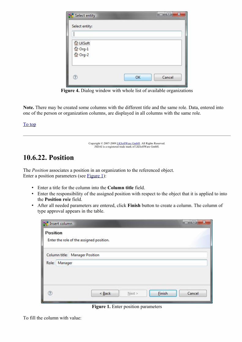
Figure 4. Dialog window with whole list of available organizations
Note. There may be created some columns with the different title and the same role. Data, entered into one of the person or organization columns, are displayed in all columns with the same role.
To top
Copyright © 2007-2009 LKSoftWare GmbH. All Rights Reserved.JSDAI is a registered trade mark of LKSoftWare GmbH.
10.6.22. PositionThe Position associates a position in an organization to the referenced object.Enter a position parameters (see Figure 1):
• Enter a title for the column into the Column title field. • Enter the responsibility of the assigned position with respect to the object that it is applied to into
the Position role field. • After all needed parameters are entered, click Finish button to create a column. The column of
type approval appears in the table.
Figure 1. Enter position parameters
To fill the column with value:

• Activate Persons and Organizations view: click on the Persons and Organizations tab or select Window -> Show view and then PDM -> Persons and Organizations (if the view is not present in the current perspective).
• Select an applicable position in the Positions tabbed panel. • Copy and paste the selected element into the Position column. You can also use drag and drop
functionality to perform the same action.
There may be created some columns with the different title and the same role. Data, entered into one of the position columns, are displayed in all columns with the same role.
To top
Copyright © 2007-2009 LKSoftWare GmbH. All Rights Reserved.JSDAI is a registered trade mark of LKSoftWare GmbH.
10.6.23. Security assignmentThe Security assignment is the level of confidentiality that is required in order to protect product data against unauthorized usage.There are no additional parameters to enter in the wizard page (see Figure 1) except a column title. Enter a column title into the Column title field and click Finish button. The column with a specified title appears in a table (see Figure 2).
Figure 1. Enter parameters of security assignment
Figure 2. Security columnFollow the routine to fill an approval column with data:
• Double click on a security column cell. The Security classification dialog window appears on the screen (see Figure 3):

Figure 3. Security classification dialog window
• Select one of the predefined values from the Level drop down list: • confidential, • proprietary, • secret, • top secret, • unclassified.
• Select an officer (a person, which is associated with some organization) in the Officer drop down list or use the button next to the field to get the whole list of available officers.
• Enter a date of approval or use the button next to the field to get the pop up calendar.
Note. If there are created a few columns of the same type, all columns for the same object contain the same data.
To top
Copyright © 2007-2009 LKSoftWare GmbH. All Rights Reserved.JSDAI is a registered trade mark of LKSoftWare GmbH.
10.6.24. Subject
The Subject specifies a the product as individual, which element is under work.There are no additional parameters to enter in the wizard page (see Figure 1) except a column title. Enter a column title into the Column title field and click Finish button. The column with a specified title appears in a table.

Figure 1. Insert column dialog to enter parameters for subject column
To fill the cell with value:
• Select an applicable product from the drop down list.
Or
• Use the button next to the field to get the whole list of available values. Select an applicable product and press OK button.
Or
• Copy and paste an applicable product from the Products view. You can also use drag and drop functionality to perform the same action.
If there are created a few columns of the same type, all columns for the same object contain the same data.
To top
Copyright © 2009 LKSoftWare GmbH. All Rights Reserved.JSDAI is a registered trade mark of LKSoftWare GmbH.
10.6.25. Surface ColorThe Surface Color specifies a colour of the surface of the referenced geometry object.There are no additional parameters to enter in the wizard page (see Figure 1) except a column title. Enter a column title into the Column title field and click Finish button.

Figure 1. Insert column dialog to enter colour information
The column of type color with a specified title appears in a table. To fill the column with value:
• Double click on the column cell or press F2 button. • Select an applicable colour in the appeared Color window and press OK button (see Figure 2).
Figure 2. Color window to select colour
• The specified colour square appears in the selected column cell (see Figure 3).
Figure 3. Surface color column with specified colour
To top
Copyright © 2009 LKSoftWare GmbH. All Rights Reserved.DJSDAI is a registered trade mark of LKSoftWare GmbH.

10.6.26. Text propertyThe Text property associates a text with a referenced object.Enter the text property parameters (see Figure 1):
• Enter a title for the column into the Column title field. • Enter an identifier of a property into the Property id field or select an applicable identifier from
the drop down list. • Enter the text, by which the text property is known, into the Property name field. • You can select which language to use for the text property:
• None (not translatable) - the content of the column is not translatable.• Default - the language, which is defined in the IDA-STEP preferences. You can change
the default language in the Language preferences page (accessible by selecting Window -> Preferences, then General -> Language).
• Specify - after this radio button is selected, you can select an applicable language in the drop down list.
• After all needed parameters are entered, click Finish button to create a column. The column with the specified column title appears in the table
Figure 1. Enter text property parameters
To fill the column cell with value, simply enter a text into the text field and press ENTER key.There may be created some columns with the different title, property name and the same property identifier. Data, entered into one of the text property columns, are displayed in all columns with the same property identifier.
To top
Copyright © 2007-2009 LKSoftWare GmbH. All Rights Reserved.JSDAI is a registered trade mark of LKSoftWare GmbH.
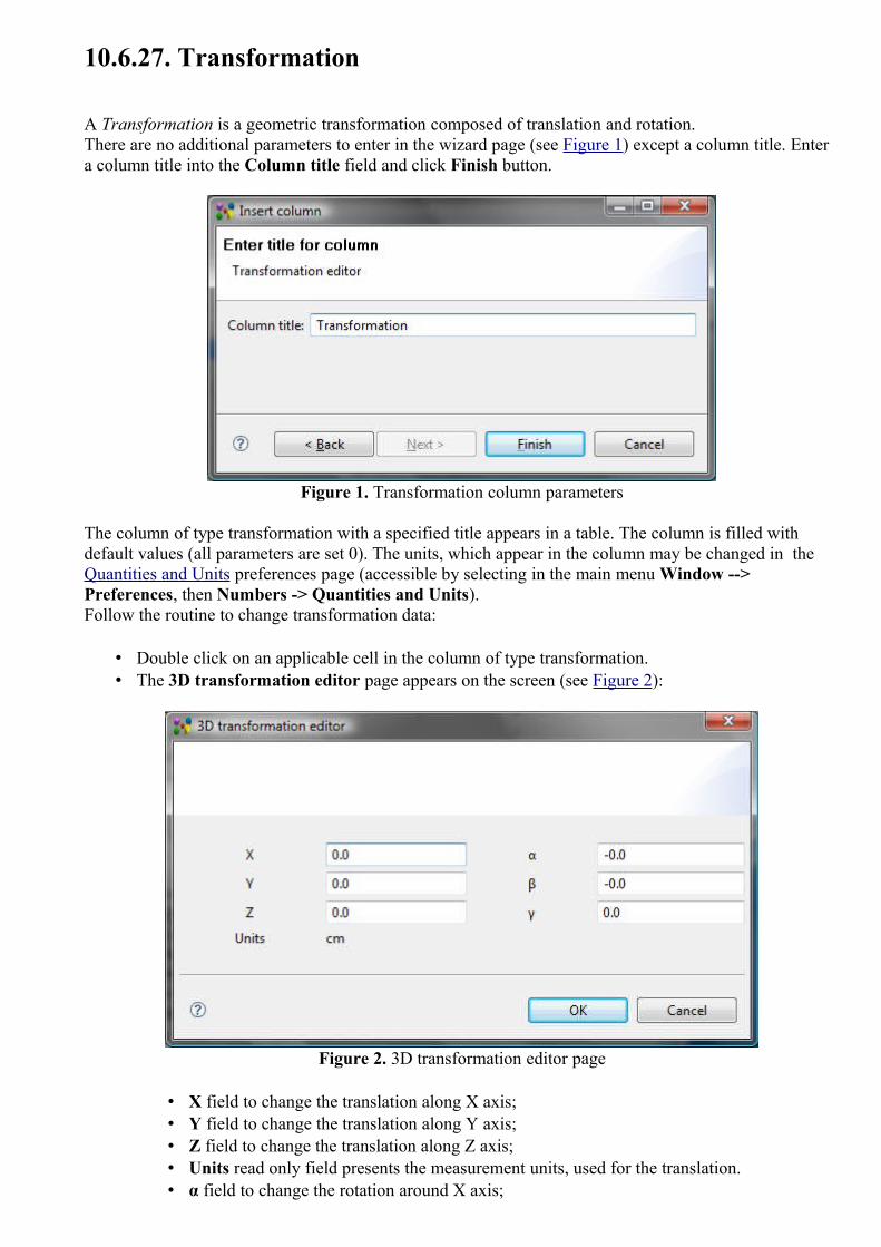
10.6.27. Transformation
A Transformation is a geometric transformation composed of translation and rotation.There are no additional parameters to enter in the wizard page (see Figure 1) except a column title. Enter a column title into the Column title field and click Finish button.
Figure 1. Transformation column parameters
The column of type transformation with a specified title appears in a table. The column is filled with default values (all parameters are set 0). The units, which appear in the column may be changed in the Quantities and Units preferences page (accessible by selecting in the main menu Window --> Preferences, then Numbers -> Quantities and Units).Follow the routine to change transformation data:
• Double click on an applicable cell in the column of type transformation. • The 3D transformation editor page appears on the screen (see Figure 2):
Figure 2. 3D transformation editor page
• X field to change the translation along X axis; • Y field to change the translation along Y axis; • Z field to change the translation along Z axis; • Units read only field presents the measurement units, used for the translation.• α field to change the rotation around X axis;

• β field to change the rotation around Y axis; • γ field to change the rotation around Z axis.
• Press OK button to confirm your changes. Note. Units in the column are converted to the units, defined in the Quantity and Units preferences.
To top
Copyright © 2009 LKSoftWare GmbH. All Rights Reserved.JSDAI is a registered trade mark of LKSoftWare GmbH.
10.6.28. Transparency InformationThe Transparency information specifies the transparency level for the referenced object.There are no additional parameters to enter in the wizard page (see Figure 1) except a column title. Enter a column title into the Column title field and click Finish button.
Figure 1. Insert column dialog to enter transparency information parameters
The column of type transparency information with a specified title appears in a table. To fill the column with value:
• Select an applicable predefined value in the Transparency column drop down list. The predefined values are: opaque, 25 %, 50 % and 75%.Or
• Enter an applicable number value into the Transparency column edit box.
To top
Copyright © 2009 LKSoftWare GmbH. All Rights Reserved.DJSDAI is a registered trade mark of LKSoftWare GmbH.
10.6.29. QuantityThe Quantity presents the quantity of the referenced object (value with unit).Enter parameters for the value with unit column (see Figure 1):
• Enter a title for the column into the Column title field.

• Enter an identifier of the quantity into the Property id field. • Enter a name of the quantity into the Property name field. • Select a quantity type from the Type drop down list. The list values are defined in the Quantities
and Units page (use main menu Windows - > Preferences -> Numbers).
Figure 1. Enter quantity parameters
• After all needed parameters are entered, click Finish button to create a column. The column of the specified type appears in the table.
To fill a column cell with value:
• Enter a number value into the text field. • Select an applicable unit from the drop down list. • Press ENTER key.
The units, and other parameters of the quantity, which appear in the column, are defined in the Quantities and Units page (use main menu Windows - > Preferences -> Numbers).There may be created some columns with the different title and the same property identifier. Data, entered into one of the columns, are displayed in all columns with the same identifier (Property id field value).
To top
Copyright © 2007-2009 LKSoftWare GmbH. All Rights Reserved.JSDAI is a registered trade mark of LKSoftWare GmbH.
10.6.30.1. Enumeration PropertyThe Enumeration Property specifies the worst possible consequence of a failure classified by the degree of injury, property damage, system damage and mission loss that could occur. Enter parameters for the enumeration property column (see Figure 1):
• Specify a title of the column to be created by entering a word or group of words into Column title field.
• Select an identifier of the property from the Property ID drop down list or enter a new value.

• Specify a name of the property by entering a word or group of words into Property name field. • Specify the enumeration in the Enums layout by selecting one of the radio buttons:
• TextEnumerationOneToTen, • FailureModeClasses, • FailureCauseClasses.
Figure 1. Enumeration property column parameters
The column of type enumeration property with a specified title appears in a table. To fill the column cell with value, select an applicable value from the drop down list.
To top
Copyright © 2009 LKSoftWare GmbH. All Rights Reserved.JSDAI is a registered trade mark of LKSoftWare GmbH.
10.6.30.2. Failure Detection MethodThe Failure Detection Method specifies the method by which a failure can be discovered by the system operator under normal system operation or by a maintenance crew carrying out a specific diagnostic action. There are no additional parameters to enter in the wizard page (see Figure 1) except a column title. Enter a column title into the Column title field and click Finish button.

Figure 1. Failure detection method column parameters
The column of type failure detection method with a specified title appears in a table. To fill the column with value or edit the existing one:
• Select an applicable predefined value from the drop down list. The predefined values are: 'Alarm', 'Built in test', 'Non destructive examination', 'Vibration analysis', 'Particle analysis', 'Chemical analysis', 'Spectographic analysis', 'Visual', 'Audible' and 'Olfactory'.Or
• Enter a word or group of words, which describe the failure detection method.
To top
Copyright © 2009 LKSoftWare GmbH. All Rights Reserved.JSDAI is a registered trade mark of LKSoftWare GmbH.
10.6.30.3. Failure EffectThe Failure effect is immediate consequences of a failure on operation, function or functionality, or status of some item.Enter parameters for the failure effect column (see Figure 1):
• Specify a title of the column to be created by entering a word or group of words into Column title field.
• Enter an identifier of the failure effect into the Id_x field. • Specify a name of the failure effect by entering a word or group of words into Name field. • Press Finish button.

Figure 1. Failure effect column parameters
The column of type failure effect with a specified title appears in a table. To fill the cell with value - type a text into the text field.
To top
Copyright © 2009 LKSoftWare GmbH. All Rights Reserved.JSDAI is a registered trade mark of LKSoftWare GmbH.
10.6.31.1. Allocated TechnologyThe Allocated technology column presents a definition of allocated passage technology. There are no additional parameters to enter in the wizard dialog page (see Figure 1), except for a column title. Enter a column title into the Column title field and click Finish button.
Figure 1. Insert column dialog to enter parameters for allocated technology column
The column with a specified title appears in a table. To fill the column with value:
• Click with a mouse or press F2 key on the column of type allocated technology to enter into edit mode.
• Select a passage technology definition from the drop down list, if present, or create a new one by entering a definition into the field.

• Press Enter key.
If there are created a few columns of the same type, all columns for the same object contain the same data.
To top
Copyright © 2009 LKSoftWare GmbH. All Rights Reserved.JSDAI is a registered trade mark of LKSoftWare GmbH.
10.6.31.2. Allowed Component Terminal ExtentThe Allowed component terminal extent property is available only for passages, which technology type is component termination. There are no additional parameters to enter in the wizard dialog window (see Figure 1), except for a column title. Enter a column title into the Column title field and click Finish button.
Figure 1. Insert column to enter parameters for allowed component terminal extent column
The column with a specified title appears in a table. To fill the column with value:
• Click with a mouse or press F2 key on the column of type allowed component terminal extent to enter into edit mode.
• You can change parameters of tolerance and units by pressing the button next to the edit field. The Tolerances wizard window appears, where you can select an applicable tolerance and create new units.
• Enter a number into the edit field. • Press Enter key. If current units are not the same as default units, the entered value is recalculated
and displayed in default units.
If there are created a few columns of the same type, all columns for the same object contain the same data.To top
Copyright © 2009 LKSoftWare GmbH. All Rights Reserved.JSDAI is a registered trade mark of LKSoftWare GmbH.
10.6.31.3. Conductive LayersThe Conductive layers column specifies a summation of the set of conductive layers in a referenced

object. There are no additional parameters to enter in the wizard dialog page (see Figure 1), except for a column title. Enter a column title into the Column title field and click Finish button.
Figure 1. Insert column dialog to enter parameters for conductive layers column
The column with a specified title appears in a table. You can not enter or edit a value in the column. The value is derivable. If there are created a few columns of the same type, all columns for the same object contain the same data.
To top
Copyright © 2009 LKSoftWare GmbH. All Rights Reserved.JSDAI is a registered trade mark of LKSoftWare GmbH.
10.6.31.4. Connected Minimum Annular RingThe Connected minimum annular ring column specifies the size of the connected minimum pad area that remains after a hole is drilled through the pad. There are no additional parameters to enter in the wizard dialog page (see Figure 1), except for a column title. Enter a column title into the Column title field and click Finish button.
Figure 1. Insert column dialog to add parameters for connected minimum annular ring column
The column with a specified title appears in a table. To fill the column with value:
• Click with a mouse or press F2 key on the column of type connected minimum annular ring to

enter into edit mode. • You can select an applicable unit from the list next to the text field. The units, and other
parameters of the quantity, which appear in the column, are defined in the Quantities and Units preferences page (use main menu Windows - > Preferences -> Numbers).
• Enter a number into the edit field. • Press Enter key. If current units are not the same as default units, the entered value is recalculated
and displayed in default units.
If there are created a few columns of the same type, all columns for the same object contain the same data.
To top
Copyright © 2009 LKSoftWare GmbH. All Rights Reserved.JSDAI is a registered trade mark of LKSoftWare GmbH.
10.6.31.5. Finished Deposition ThicknessThe Finished deposition thickness column specifies the finished thickness of a particular deposition material for a passage. There are no additional parameters to enter in the wizard dialog window (see Figure 1), except for a column title. Enter a column title into the Column title field and click Finish button.
Figure 1. Insert column dialog to enter parameters for finished deposition thickness column
The column with a specified title appears in a table. To fill the column with value:
• Click with a mouse or press F2 key on the column of type finished deposition thickness to enter into edit mode.
• You can change parameters of tolerance and units by pressing the button next to the edit field. The Tolerances wizard window appears, where you can select an applicable tolerance and create new units.
• Enter a number into the edit field. • Press Enter key. If current units are not the same as default units, the entered value is recalculated
and displayed in default units.
If there are created a few columns of the same type, all columns for the same object contain the same data.
To top

Copyright © 2009 LKSoftWare GmbH. All Rights Reserved.JSDAI is a registered trade mark of LKSoftWare GmbH.
10.6.31.6. Finished Passage ExtentThe Finished passage extent column specifies a minimal size of the finished passage. There are no additional parameters to enter in the wizard dialog window (see Figure 1), except for a column title. Enter a column title into the Column title field and click Finish button.
Figure 1. Insert column dialog to enter parameters for finished passage extent column
The column with a specified title appears in a table. To fill the column with value:
• Click with a mouse or press F2 key on the column of type finished passage extent to enter into edit mode.
• You can change parameters of tolerance and units by pressing the button next to the edit field. The Tolerances wizard window appears, where you can select an applicable tolerance and create new units.
• Enter a number into the edit field. • Press Enter key. If current units are not the same as default units, the entered value is recalculated
and displayed in default units.
If there are created a few columns of the same type, all columns for the same object contain the same data.To top
Copyright © 2009 LKSoftWare GmbH. All Rights Reserved.JSDAI is a registered trade mark of LKSoftWare GmbH.
10.6.31.7. FromThe From column presents the current passage technology allocation to the stack model - the top most stratum the passage is passing through, if the passage orientation is top-bottom, and the bottom most stratum otherwise.There are no additional parameters to enter in the wizard dialog page (see Figure 1), except for a column title. Enter a column title into the Column title field and click Finish button.

Figure 1. Insert column to enter parameters for passage technology allocation to stack model column
The column with a specified title appears in a table. To fill the column with value:
• Select an applicable layer in the Stratum view tree table. • Drag the selected layer and drop on the destination cell (recently created).
If there are created a few columns of the same type, all columns for the same object contain the same data.
To top
Copyright © 2009 LKSoftWare GmbH. All Rights Reserved.JSDAI is a registered trade mark of LKSoftWare GmbH.
10.6.31.8. Laminate Stiffness ClassThe Laminate Stiffness Class associates the classification of the laminate stiffness to the referenced object.There are no additional parameters to enter in the wizard dialog page (see Figure 1), except a column title. Enter a column title into the Column title field and click Finish button.
Figure 1. Insert column dialog to enter parameters for laminate stiffness class column
The column with a specified title appears in a table. To fill the column with value:
• Click with a mouse or press F2 key on the column of type laminate stiffness class to enter into edit mode.

• Select an applicable value in the r/o combo box. The following values can be selected: • Fluid like with constant thickness - a laminate is a fluid like and the thickness of this
laminate is constant; • Fluid like with varying thickness - a laminate is a fluid like and the thickness of this
laminate is varying; • Stiff laminate - a laminate is stiff.
If there are created a few columns of the same type, all columns for the same object contain the same data.
To top
Copyright © 2009 LKSoftWare GmbH. All Rights Reserved.JSDAI is a registered trade mark of LKSoftWare GmbH.
10.6.31.9. Layer PositionThe Layer position associates a position with a references object. There are no additional parameters to enter in the wizard dialog page (see Figure 1), except a column title. Enter a column title into the Column title field and click Finish button.
Figure 1. Insert column dialog to enter parameters for layer position column
The column with a specified title appears in a table. To fill the column with value:
• Click with a mouse or press F2 key on the column of type layer possition to enter into edit mode. • Select an applicable value in the r/o combo box. The following values can be selected:
• All, • Internal, • External,• Primary, • Secondary.
If there are created a few columns of the same type, all columns for the same object contain the same data.To top
Copyright © 2009 LKSoftWare GmbH. All Rights Reserved.JSDAI is a registered trade mark of LKSoftWare GmbH.

10.6.31.10. Maximum Aspect RatioThe Maximum aspect ratio column specifies a maximum value of the aspect ratio for a particular passage.
There are no additional parameters to enter in the wizard dialog window (see Figure 1), except for a column title. Enter a column title into the Column title field and click Finish button.
Figure 1. Insert column dialog to enter parameters for maximum aspect ratio column
The column with a specified title appears in a table. To fill the column with value:
• Click with a mouse or press F2 key on the column of type maximum aspect ratio to enter into edit mode.
• Enter a number into the edit field. • Press Enter key.
Parameters of the quantity, which appear in the column, are defined in the Quantities and Units preferences page (use main menu Windows - > Preferences -> Numbers).If there are created a few columns of the same type, all columns for the same object contain the same data.
To top
Copyright © 2009 LKSoftWare GmbH. All Rights Reserved.JSDAI is a registered trade mark of LKSoftWare GmbH.
10.6.31.11. Maximum Feature Size RequirementThe Maximum feature size requirement associates a maximum feature size requirement with a referenced object. There are no additional parameters to enter in the wizard dialog page (see Figure 1), except a column title. Enter a column title into the Column title field and click Finish button.

Figure 1. Insert column dialog to enter parameters for maximum feature size requirement column
The column with a specified title appears in a table. To fill the column with value:
• Click with a mouse or press F2 key on the column of type maximum feature size requirement to enter into edit mode.
• You can select an applicable unit in the list next to the text field. The units, and other parameters of the quantity, which appear in the column, are defined in the Quantities and Units page (use main menu Windows - > Preferences -> Numbers).
• Enter a number into the edit field. • Press Enter key. If current units are not the same as default units, the entered value is recalculated
and displayed in default units.
If there are created a few columns of the same type, all columns for the same object contain the same data.
To top
Copyright © 2009 LKSoftWare GmbH. All Rights Reserved.JSDAI is a registered trade mark of LKSoftWare GmbH.
10.6.31.12. Minimum Aspect RatioThe Minimum aspect ratio column specifies a minimum value of the aspect ratio of the referenced object. There are no additional parameters to enter in the wizard page (see Figure 1), except a column title. Enter a column title into the Column title field and click Finish button.
Figure 1. Insert column dialog to enter parameters for minimum aspect ratio column

The column with a specified title appears in a table. To fill the column with value:
• Click with a mouse or press F2 key on the column of type minimum aspect ratio to enter into edit mode.
• Enter a numeric value into the field. • Press Enter key.
Parameters of the quantity, which appear in the column, are defined in the Quantities and Units preferences page (use main menu Windows - > Preferences -> Numbers).If there are created a few columns of the same type, all columns for the same object contain the same data.
To top
Copyright © 2009 LKSoftWare GmbH. All Rights Reserved.JSDAI is a registered trade mark of LKSoftWare GmbH.
10.6.31.13. Minimum Finished Feature SizeThe Minimum finished feature size identifies a minimum finished feature size for the referenced object. There are no additional parameters to enter in the wizard dialog page (see Figure 1), except for a column title. Enter a column title into the Column title field and click Finish button.
Figure 1. Insert column dialog to enter parameters for minimum finished feature size column
The column with a specified title appears in a table. To fill the column with value:
• Click with a mouse or press F2 key on the column of type minimum finished feature size to enter into edit mode.
• You can select an applicable unit in the list next to the text field. The units, and other parameters of the quantity, which appear in the column, are defined in the Quantities and Units preferences page (use main menu Windows - > Preferences -> Numbers).
• Enter a number into the edit field. • Press Enter key. If current units are not the same as default units, the entered value is recalculated
and displayed in default units.
If there are created a few columns of the same type, all columns for the same object contain the same data.
To top

Copyright © 2009 LKSoftWare GmbH. All Rights Reserved.JSDAI is a registered trade mark of LKSoftWare GmbH.
10.6.31.14. Minimum Finished Feature SpacingThe Minimum finished feature spacing identifies a minimum finished feature spacing for the referenced object. There are no additional parameters to enter in the wizard dialog page (see Figure 1), except a column title. Enter a column title into the Column title field and click Finish button.
Figure 1. Insert column dialog to enter parameters for minimum finished feature spacing column
The column with a specified title appears in a table. To fill the column with value:
• Click with a mouse or press F2 key on the column of type minimum finished feature spacing to enter into edit mode.
• You can select an applicable unit from the list next to the text field. The units, and other parameters of the quantity, which appear in the column, are defined in the Quantities and Units preferences page (use main menu Windows - > Preferences -> Numbers).
• Enter a number into the edit field. • Press Enter key. If current units are not the same as default units, the entered value is recalculated
and displayed in default units.
If there are created a few columns of the same type, all columns for the same object contain the same data.
To top
Copyright © 2009 LKSoftWare GmbH. All Rights Reserved.JSDAI is a registered trade mark of LKSoftWare GmbH.
10.6.31.15. Minimum Finished SizeThe Minimum finished size column specifies a minimum size of a passage after all adjacent components are built in. There are no additional parameters to enter in the wizard dialog page (see Figure 1), except for a column title. Enter a column title into the Column title field and click Finish button.

Figure 1. Insert column dialog to enter parameters for minimum finished size column
The column with a specified title appears in a table. To fill the column with value:
• Click with a mouse or press F2 key on the column of type minimum finished size to enter into edit mode.
• You can select an applicable unit from the list next to the text field. The units, and other parameters of the quantity, which appear in the column, are defined in the Quantities and Units preferences page (use main menu Windows - > Preferences -> Numbers).
• Enter a number into the edit field. • Press Enter key. If current units are not the same as default units, the entered value is recalculated
and displayed in default units.
If there are created a few columns of the same type, all columns for the same object contain the same data.To top
Copyright © 2009 LKSoftWare GmbH. All Rights Reserved.JSDAI is a registered trade mark of LKSoftWare GmbH.
10.6.31.16. Minimum Interior ExtentThe Minimum interior extent column specifies the minimal size of the interior for a passage. This characteristic is available only for a passage, which technology type is via. There are no additional parameters to enter in the wizard dialog page (see Figure 1), except for a column title. Enter a column title into the Column title field and click Finish button.

Figure 1. Insert column dialog to enter parameters for minimum interior extent column
The column with a specified title appears in a table. To fill the column with value:
• Click with a mouse or press F2 key on the column of type minimum interior extent to enter into edit mode.
• You can change parameters of tolerance and units by pressing the button next to the edit field. The Tolerances wizard window appears, where you can select an applicable tolerance and create new units.
• Enter a number into the edit field. • Press Enter key. If current units are not the same as default units, the entered value is recalculated
and displayed in default units.
If there are created a few columns of the same type, all columns for the same object contain the same data.
To top
Copyright © 2009 LKSoftWare GmbH. All Rights Reserved.JSDAI is a registered trade mark of LKSoftWare GmbH.
10.6.31.17. Passage Deposition Material AttributeThe Passage deposition material attribute is a characteristic that depends on the deposition material aspects. Enter parameters for a passage deposition material attribute column (see Figure 1):
• Enter a title for the column into the Column title field. • Select a conductivity classification to be associated with a deposition material from the Attribute
layout by selecting the particular radio button: • Electric conductivity - is a measure of a material's ability to conduct an electric current; • Thermal conductivity - is the property of a material that indicates its ability to conduct
heat; • Magnetic permeability - is the degree of magnetization of a material that responds
linearly to an applied magnetic field; • Optical insertion loss - is the loss of signal power resulting from the insertion of a device
in an optical fiber; • Dielectric permittivity - is a physical quantity that describes how an electric field affects,
and is affected by a dielectric medium, and is determined by the ability of a material to polarize in response to the field, and thereby reduce the total electric field inside the material.
• Press Finish button to create a column.

Figure 1. Insert column dialog to enter parameters for passage deposition material attribute column
The column with a specified title appears in a table. To fill the column with value:
• Click with a mouse or press F2 key on the column of type passage deposition material attribute to enter into edit mode.
• Select an applicable value from the combo box. The values in the list depend on the conductivity classification, selected in the wizard window:
• Electrical conductivity classification column contains the predefined values: conductive, non conductive, resistive, semi conductive and super conductive.
• Thermal conductivity classification column contains the predefined values: conductive, non conductive, resistive, semi conductive and super conductive.
• Magnetic permeability classification column contains the predefined values: free space permeability, low permeability, medium permeability and highly permeable.
• Optical insertion loss classification column contains the predefined values: vacuum, very low loss, low loss, medium loss and high loss.
• Dielectric permittivity classification column contains the predefined values: vacuum permittivity, low permittivity, medium permittivity and high permittivity.
• Press Enter key.
If there are created a few columns of the same type, all columns for the same object contain the same data.
To top
Copyright © 2009 LKSoftWare GmbH. All Rights Reserved.JSDAI is a registered trade mark of LKSoftWare GmbH.
10.6.31.18. Passage Deposition Material IdentificationThe Passage deposition material identification column specifies a deposition material of a passage. There are no additional parameters to enter in the wizard dialog page (see Figure 1), except for a column title. Enter a column title into the Column title field and click Finish button.

Figure 1. Insert column dialog to enter parameters for passage deposition material identification column
The column with a specified title appears in a table. To fill the column with value:
• Click with a mouse or press F2 key on the column of type passage deposition material identification to enter into edit mode.
• The 'CUSTOM' material identification appears in the editable combo box. You can select another material identification in the list, if present, or create a new one by entering an identification into the field.
• Press Enter key.
If there are created a few columns of the same type, all columns for the same object contain the same data.
To top
Copyright © 2009 LKSoftWare GmbH. All Rights Reserved.JSDAI is a registered trade mark of LKSoftWare GmbH.
10.6.31.19. Passage Filling Material AttributeThe Passage filling material attribute is a characteristic that depends on the filling material aspects. Enter parameters for a passage filling material attribute column (see Figure 1):
• Enter a title for the column into the Column title field. • Select a conductivity classification to be associated with a filling material from the Attribute
layout by selecting the particular radio button: • Electric conductivity - is a measure of a material's ability to conduct an electric current; • Thermal conductivity - is the property of a material that indicates its ability to conduct
heat; • Magnetic permeability - is the degree of magnetization of a material that responds
linearly to an applied magnetic field; • Optical insertion loss - is the loss of signal power resulting from the insertion of a device
in an optical fiber; • Dielectric permittivity - is a physical quantity that describes how an electric field affects,
and is affected by a dielectric medium, and is determined by the ability of a material to polarize in response to the field, and thereby reduce the total electric field inside the material.
• Press Finish button to create a column.

Figure 1. Insert column dialog to enter parameters for passage filling material attribute column
The column with a specified title appears in a table. To fill the column with value:
• Click with a mouse or press F2 key on the column of type passage filling material attribute to enter into edit mode.
• Select an applicable value from the combo box. The values in the list depend on the conductivity classification, selected in the wizard window:
• Electrical conductivity classification column contains the predefined values: conductive, non conductive, resistive, semi conductive and super conductive.
• Thermal conductivity classification column contains the predefined values: conductive, non conductive, resistive, semi conductive and super conductive.
• Magnetic permeability classification column contains the predefined values: free space permeability, low permeability, medium permeability and highly permeable.
• Optical insertion loss classification column contains the predefined values: vacuum, very low loss, low loss, medium loss and high loss.
• Dielectric permittivity classification column contains the predefined values: vacuum permittivity, low permittivity, medium permittivity and high permittivity.
• Press Enter key.
If there are created a few columns of the same type, all columns for the same object contain the same data.To top
Copyright © 2009 LKSoftWare GmbH. All Rights Reserved.JSDAI is a registered trade mark of LKSoftWare GmbH.
10.6.31.20. Passage Filling Material IdentificationThe Passage filling material identification column specifies a deposition material of a passage. There are no additional parameters to enter in the wizard dialog page (see Figure 1), except for a column title. Enter a column title into the Column title field and click Finish button.

Figure 1. Insert column dialog to enter parameters for passage filling material identification column
The column with a specified title appears in a table. To fill the column with value:
• Click with a mouse or press F2 key on the column of type passage filling material identification to enter into edit mode.
• The 'CUSTOM' material identification appears in the editable combo box. You can select another material identification in the list, if present, or create a new one by entering an identification into the field.
• Press Enter key.
If there are created a few columns of the same type, all columns for the same object contain the same data.
To top
Copyright © 2009 LKSoftWare GmbH. All Rights Reserved.JSDAI is a registered trade mark of LKSoftWare GmbH.
10.6.31.21. Passage Terminus ConditionThe Passage terminus condition column specifies a terminus condition of a passage. There are no additional parameters to enter in the wizard dialog page (see Figure 1), except for a column title. Enter a column title into the Column title field and click Finish button.
Figure 1. Insert column dialog to enter parameters for passage terminus condition column

The column with a specified title appears in a table. To fill the column with value:
• Click with a mouse or press F2 key on the column of type passage terminus condition to enter into edit mode.
• Select an applicable value in the r/o combo box. The following values can be selected: • Bilateral bond;• Bilateral complete removal; • Unilateral bond.
• Press Enter key.
If there are created a few columns of the same type, all columns for the same object contain the same data.
To top
Copyright © 2009 LKSoftWare GmbH. All Rights Reserved.JSDAI is a registered trade mark of LKSoftWare GmbH.
10.6.31.22. Plated PassageThe Plated passage column specifies the plating feature of a passage (whether passage is plated or not). There are no additional parameters to enter in the wizard dialog page (see Figure 1), except for a column title. Enter a column title into the Column title field and click Finish button.
Figure 1. Insert column dialog to enter parameters for plated passage column
The column with a specified title appears in a table. To fill the column with value:
• Click with a mouse or press F2 key on the column of type plated passage to set one of the available values:
• Plated, • Unplated.
• Press Enter key.
If there are created a few columns of the same type, all columns for the same object contain the same data.
To top
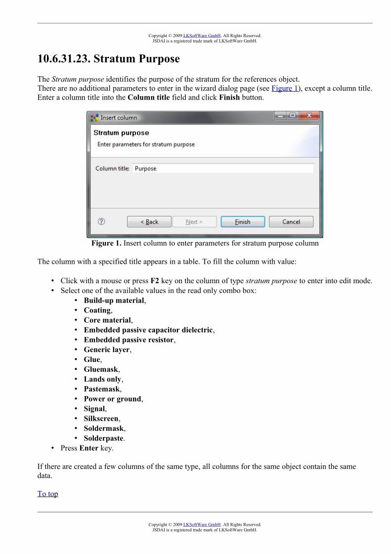
Copyright © 2009 LKSoftWare GmbH. All Rights Reserved.JSDAI is a registered trade mark of LKSoftWare GmbH.
10.6.31.23. Stratum PurposeThe Stratum purpose identifies the purpose of the stratum for the references object. There are no additional parameters to enter in the wizard dialog page (see Figure 1), except a column title. Enter a column title into the Column title field and click Finish button.
Figure 1. Insert column to enter parameters for stratum purpose column
The column with a specified title appears in a table. To fill the column with value:
• Click with a mouse or press F2 key on the column of type stratum purpose to enter into edit mode. • Select one of the available values in the read only combo box:
• Build-up material, • Coating, • Core material, • Embedded passive capacitor dielectric, • Embedded passive resistor, • Generic layer, • Glue, • Gluemask, • Lands only, • Pastemask, • Power or ground, • Signal, • Silkscreen, • Soldermask, • Solderpaste.
• Press Enter key.
If there are created a few columns of the same type, all columns for the same object contain the same data.
To top
Copyright © 2009 LKSoftWare GmbH. All Rights Reserved.JSDAI is a registered trade mark of LKSoftWare GmbH.

10.6.31.24. Stratum Technology Material DesignationThe Stratum technology material designation column specifies a text, that is used in a stratum technology to label a material. There are no additional parameters to enter in the wizard dialog page (see Figure 1), except a column title. Enter a column title into the Column title field and click Finish button.
Figure 1. Insert column dialog to enter parameters for stratum technology material designation column
The column with a specified title appears in a table. To fill the column with value:
• Click with a mouse or press F2 key on the column of type stratum technology material designation to enter into edit mode.
• Enter an applicable material designation text into the edit field. • Press Enter key.
If there are created a few columns of the same type, all columns for the same object contain the same data.
To top
Copyright © 2009 LKSoftWare GmbH. All Rights Reserved.JSDAI is a registered trade mark of LKSoftWare GmbH.
10.6.31.25. Stratum Technology Occurrence BaseThe Stratum Technology Occurrence Base column presents the base value (down, independent or up) of a stratum technology occurrence. One stratum can be based on another stratum. For example stratum A can be based on stratum B, but stratum B can not be based on stratum A at the same time.There are no additional parameters to enter in the wizard dialog page (see Figure 1), except for a column title. Enter a column title into the Column title field and click Finish button.

Figure 1. Insert column dialog to enter parameters for base of stratum technology occurrence column
The column with a specified title appears in a table. To fill the column with value:
• Click with a mouse or press F2 key on the column of type stratum technology occurrence base to enter into edit mode.
• Select an applicable value in the r/o combo box. The following values can be selected: • Down;• Independent; • Up.
• Press Enter key.
If there are created a few columns of the same type, all columns for the same object contain the same data.
To top
Copyright © 2009 LKSoftWare GmbH. All Rights Reserved.JSDAI is a registered trade mark of LKSoftWare GmbH.
10.6.31.26. Stratum Technology Occurrence DefinitionThe Startum technology occurrence definition presents an explanation of the stratum technology occurrence. There are no additional parameters to enter in the wizard dialog page (see Figure 1), except for a column title. Enter a column title into the Column title field and click Finish button.
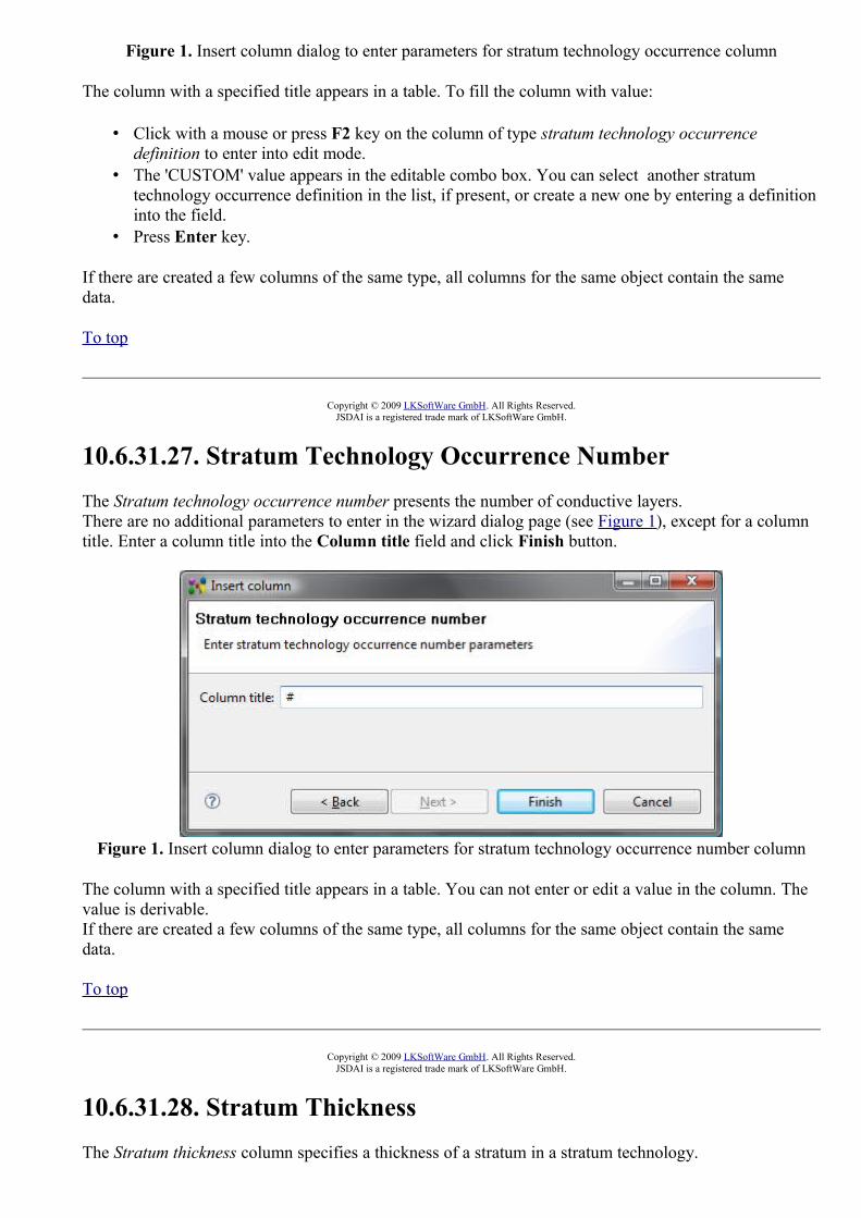
Figure 1. Insert column dialog to enter parameters for stratum technology occurrence column
The column with a specified title appears in a table. To fill the column with value:
• Click with a mouse or press F2 key on the column of type stratum technology occurrence definition to enter into edit mode.
• The 'CUSTOM' value appears in the editable combo box. You can select another stratum technology occurrence definition in the list, if present, or create a new one by entering a definition into the field.
• Press Enter key.
If there are created a few columns of the same type, all columns for the same object contain the same data.
To top
Copyright © 2009 LKSoftWare GmbH. All Rights Reserved.JSDAI is a registered trade mark of LKSoftWare GmbH.
10.6.31.27. Stratum Technology Occurrence NumberThe Stratum technology occurrence number presents the number of conductive layers. There are no additional parameters to enter in the wizard dialog page (see Figure 1), except for a column title. Enter a column title into the Column title field and click Finish button.
Figure 1. Insert column dialog to enter parameters for stratum technology occurrence number column
The column with a specified title appears in a table. You can not enter or edit a value in the column. The value is derivable. If there are created a few columns of the same type, all columns for the same object contain the same data.
To top
Copyright © 2009 LKSoftWare GmbH. All Rights Reserved.JSDAI is a registered trade mark of LKSoftWare GmbH.
10.6.31.28. Stratum ThicknessThe Stratum thickness column specifies a thickness of a stratum in a stratum technology.

There are no additional parameters to enter in the wizard dialog page (see Figure 1), except for a column title. Enter a column title into the Column title field and click Finish button.
Figure 1. Insert column dialog to enter parameters for stratum technology stratum thickness column
The column with a specified title appears in a table. To fill the column with value:
• Click with a mouse or press F2 key on the column of type stratum thickness to enter into edit mode.
• You can change parameters of tolerance and units by pressing the button next to the edit field. The Tolerances wizard window appears, where you can select an applicable tolerance and create new units.
• Enter a number into the edit field. • Press Enter key. If current units are not the same as default units, the entered value is recalculated
and displayed in default units.
If there are created a few columns of the same type, all columns for the same object contain the same data.
To top
Copyright © 2009 LKSoftWare GmbH. All Rights Reserved.JSDAI is a registered trade mark of LKSoftWare GmbH.
10.6.31.29. Technology TypeThe Technology type column specifies a type of technology for a referenced object. There are no additional parameters to enter in the wizard dialog page (see Figure 1), except for a column title. Enter a column title into the Column title field and click Finish button.

Figure 1. Insert column dialog to enter parameters for technology type column
The column with a specified title appears in a table and automatically filled with a particular value, which is associated to the referenced object. You can edit the column value:
• Click with a mouse or press F2 key on the column of type technology type to set one of the available values:
• Border, • Component termination, • Unsupported, • Via.
• Press Enter key.
If there are created a few columns of the same type, all columns for the same object contain the same data.
To top
Copyright © 2009 LKSoftWare GmbH. All Rights Reserved.JSDAI is a registered trade mark of LKSoftWare GmbH.
10.6.31.30. ToThe To column presents the current passage technology allocation to the stack model - the top most stratum the passage is passing through, if the passage orientation is bottom-top, and the bottom most stratum otherwise.There are no additional parameters to enter in the wizard dialog page (see Figure 1), except for a column title. Enter a column title into the Column title field and click Finish button.

Figure 1. Insert column dialog to enter parameters for passage technology allocation to stack model column
The column with a specified title appears in a table. To fill the column with value:
• Select an applicable layer in the Stratum view tree table. • Drag the selected layer and drop on the destination cell (recently created).
If there are created a few columns of the same type, all columns for the same object contain the same data.
To top
Copyright © 2009 LKSoftWare GmbH. All Rights Reserved.JSDAI is a registered trade mark of LKSoftWare GmbH.
10.6.31.31. Total ThicknessThe Total thickness presents the summation of the set of layer thicknesses in the referenced object. There are no additional parameters to enter in the wizard dialog page (see Figure 1), except for a column title. Enter a column title into the Column title field and click Finish button.
Figure 1. Insert column dialog to enter parameters for total thickness column
The column with a specified title appears in a table. You can not enter or edit a value in the column. The value is derivable. It summarizes the thickness of all layers, which are included in the referenced object.If there are created a few columns of the same type, all columns for the same object contain the same

data.
To top
Copyright © 2009 LKSoftWare GmbH. All Rights Reserved.JSDAI is a registered trade mark of LKSoftWare GmbH.
10.6.31.32. Unconnected Minimum Annular RingThe Unconnected minimum annular ring column specifies the size of the unconnected minimum pad area that remains after a hole is drilled through the pad. There are no additional parameters to enter in the wizard dialog page (see Figure 1), except for a column title. Enter a column title into the Column title field and click Finish button.
Figure 1. Insert column dialog to add parameters for unconnected minimum annular ring column
The column with a specified title appears in a table. To fill the column with value:
• Click with a mouse or press F2 key on the column of type unconnected minimum annular ring to enter into edit mode.
• You can select an applicable unit from the list next to the text field. The units, and other parameters of the quantity, which appear in the column, are defined in the Quantities and Units preferences page (use main menu Windows - > Preferences -> Numbers).
• Enter a number into the edit field. • Press Enter key. If current units are not the same as default units, the entered value is recalculated
and displayed in default units.
If there are created a few columns of the same type, all columns for the same object contain the same data.
To top
Copyright © 2009 LKSoftWare GmbH. All Rights Reserved.JSDAI is a registered trade mark of LKSoftWare GmbH.
10.7. Columns PerspectiveA perspective defines the initial set of columns in a table of a particular view. Each view has default perspective of columns. The user can create, select the created one or reset to default perspective.
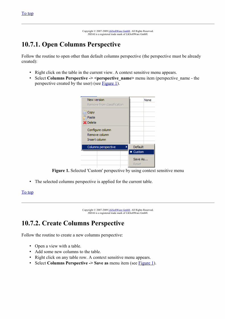
To top
Copyright © 2007-2009 LKSoftWare GmbH. All Rights Reserved.JSDAI is a registered trade mark of LKSoftWare GmbH.
10.7.1. Open Columns PerspectiveFollow the routine to open other than default columns perspective (the perspective must be already created):
• Right click on the table in the current view. A context sensitive menu appears. • Select Columns Perspective -> <perspective_name> menu item (perspective_name - the
perspective created by the user) (see Figure 1).
Figure 1. Selected 'Custom' perspective by using context sensitive menu
• The selected columns perspective is applied for the current table.
To top
Copyright © 2007-2009 LKSoftWare GmbH. All Rights Reserved.JSDAI is a registered trade mark of LKSoftWare GmbH.
10.7.2. Create Columns PerspectiveFollow the routine to create a new columns perspective:
• Open a view with a table. • Add some new columns to the table. • Right click on any table row. A context sensitive menu appears. • Select Columns Perspective -> Save as menu item (see Figure 1).

Figure 1. Selected Save as menu item
• The Save Columns Perspective As dialog window appears on the screen (see Figure 2):
Figure 2. Save Columns Perspective As dialog window
• Enter a name of the columns perspective into the Name field . • Click Ok button. The created perspective appears in the context sensitive menu list,
marked with the bullet.
Or
• Reuse already created perspective name by selecting one from the Existing columns perspectives list:
• The dialog window appears to confirm, whether you want to overwrite the perspective name or not (see Figure 3).

Figure 3. Overwrite columns perspective dialog window
• Click Yes button to overwrite the perspective name. The created perspective appears in the context sensitive menu list, marked with the bullet.Or
• Click No button to go back to the Save Columns Perspective As dialog window.Or
• Click Cancel button to quit the creating of a new columns perspective.
To top
Copyright © 2007-2009 LKSoftWare GmbH. All Rights Reserved.JSDAI is a registered trade mark of LKSoftWare GmbH.
10.7.3. Rearrange ColumnsFollow the routine to rearrange dynamic columns in a columns perspective:
• Right click on a table in a particular view. • Select the Columns perspective -> Rearrange menu item in the appeared context sensitive menu.
The Rearrangement dialog window appears on the screen (see Figure 1):
Figure 1. Rearrangement dialog window
• Select a name of the column you want to change the order in the table. • Use the arrow buttons up or down on the right of the window to move the selected column
up or down the list. • Press OK button to confirm your changes or Cancel button to cancel the rearrangement.
To top
Copyright © 2009 LKSoftWare GmbH. All Rights Reserved.JSDAI is a registered trade mark of LKSoftWare GmbH.

10.7.4. Reset Default Columns PerspectiveFollow the routine to reset the default columns perspective if you have made any changes to it:
• Right click on any table row. A context sensitive menu appears. • Select the Columns Perspective -> Reset menu item. • The initial defalt columns perspective layout appears on the screen.
Note. You can reset only the default columns perspective, for other columns perspectives the Reset menu item is disabled.To top
Copyright © 2007-2009 LKSoftWare GmbH. All Rights Reserved.JSDAI is a registered trade mark of LKSoftWare GmbH.
11. PrintingIDA-STEP provides possibility to print an active view or selected views, which are currently opened in IDA-STEP. You can select an applicable printing option in the main menu bar by selecting:
• File -> Print - this option is enabled if a particular view is activated in IDA-STEP window;• File -> Print views.

Figure 1. IDA-STEP window, File menu items.
After the Print menu item is selected, only the currently activated view appears in the Print preview window (see Figure 2):

Figure 2. Print preview page of the current viewTo top
Print views
If the Print views option is selected in the File menu, the Select views dialogue window to select applicable views appears on the screen (see Figure 3):
Figure 3. Select views dialogue window
• Choose views to be printed by selecting a check box in front of the particular view name in the Select the items list.

• Use Select All button to select all views, presented in the Select the item list. To unselect selected view(s), press Deselect All button.
• Press OK button to confirm your selection.
The Print preview window appears with recently selected views (see Figure 4).
Figure 4. Print preview page with one of selected viewsTo top
Print preview settings
The Print preview page typically uses some default settings such as page size, layout and etc..
• Print button - the Print wizard is invoked to select a printer and change the selected printer settings.
• Previous view button - press the button to review the previous view. • Next view button - press the button to review the next view. • Text field next to the Next view button indicates the number of the current view in the preview
page - you can enter a number of a view to be activated in the preview page. The read only label next to the text field presents the header of the view, which is presented.
• Previous page button - go to the previous page.• Next page button - go to the next page. • Page number text field next to the Next page button indicates the number of the page for the
current view - you can enter the number of the page to be shown in the Print preview window. • Zoom text field - enter an applicable zoom value or select the one from the drop down list. The
preview page should be resized according entered/selected value.• Page Preview: Multiple Pages - select a combination of pages the selected view to be
previewed on. This is useful, if there is a need to preview a single view on multiple pages.• Settings button - press this button to invoke the wizard page to change the printing parameters
(see Figure 5):
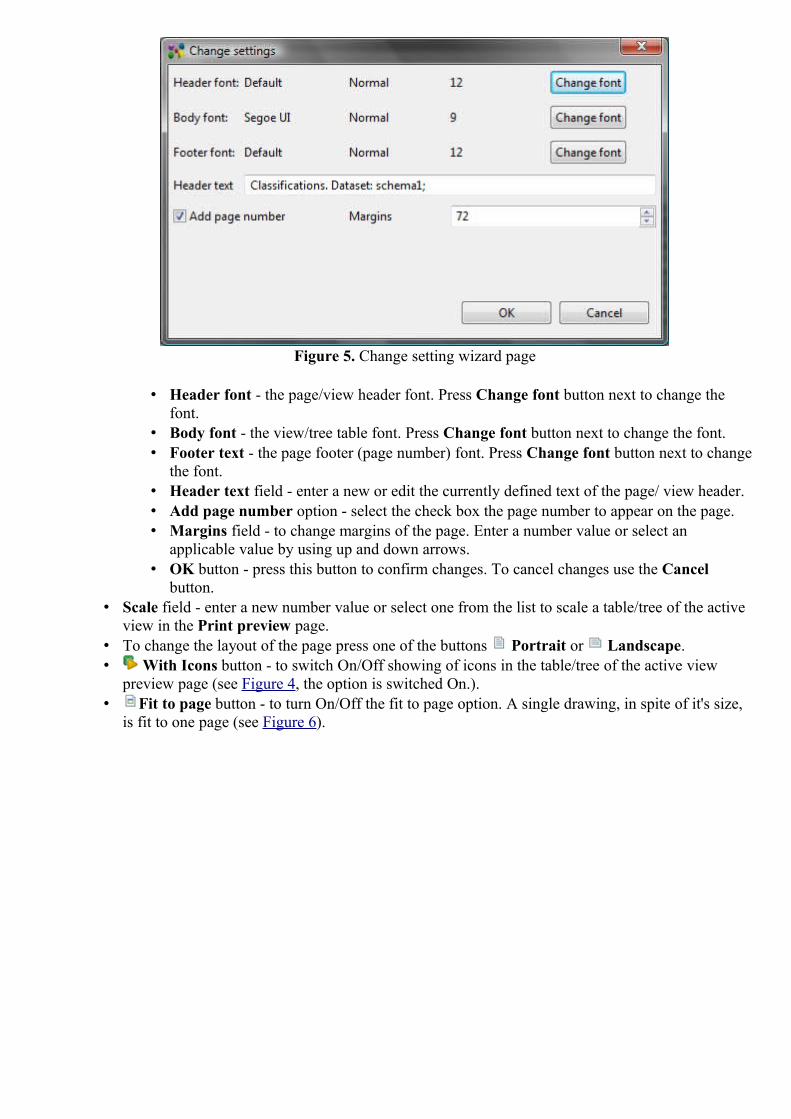
Figure 5. Change setting wizard page
• Header font - the page/view header font. Press Change font button next to change the font.
• Body font - the view/tree table font. Press Change font button next to change the font. • Footer text - the page footer (page number) font. Press Change font button next to change
the font. • Header text field - enter a new or edit the currently defined text of the page/ view header. • Add page number option - select the check box the page number to appear on the page. • Margins field - to change margins of the page. Enter a number value or select an
applicable value by using up and down arrows. • OK button - press this button to confirm changes. To cancel changes use the Cancel
button. • Scale field - enter a new number value or select one from the list to scale a table/tree of the active
view in the Print preview page. • To change the layout of the page press one of the buttons Portrait or Landscape. • With Icons button - to switch On/Off showing of icons in the table/tree of the active view
preview page (see Figure 4, the option is switched On.). • Fit to page button - to turn On/Off the fit to page option. A single drawing, in spite of it's size,
is fit to one page (see Figure 6).
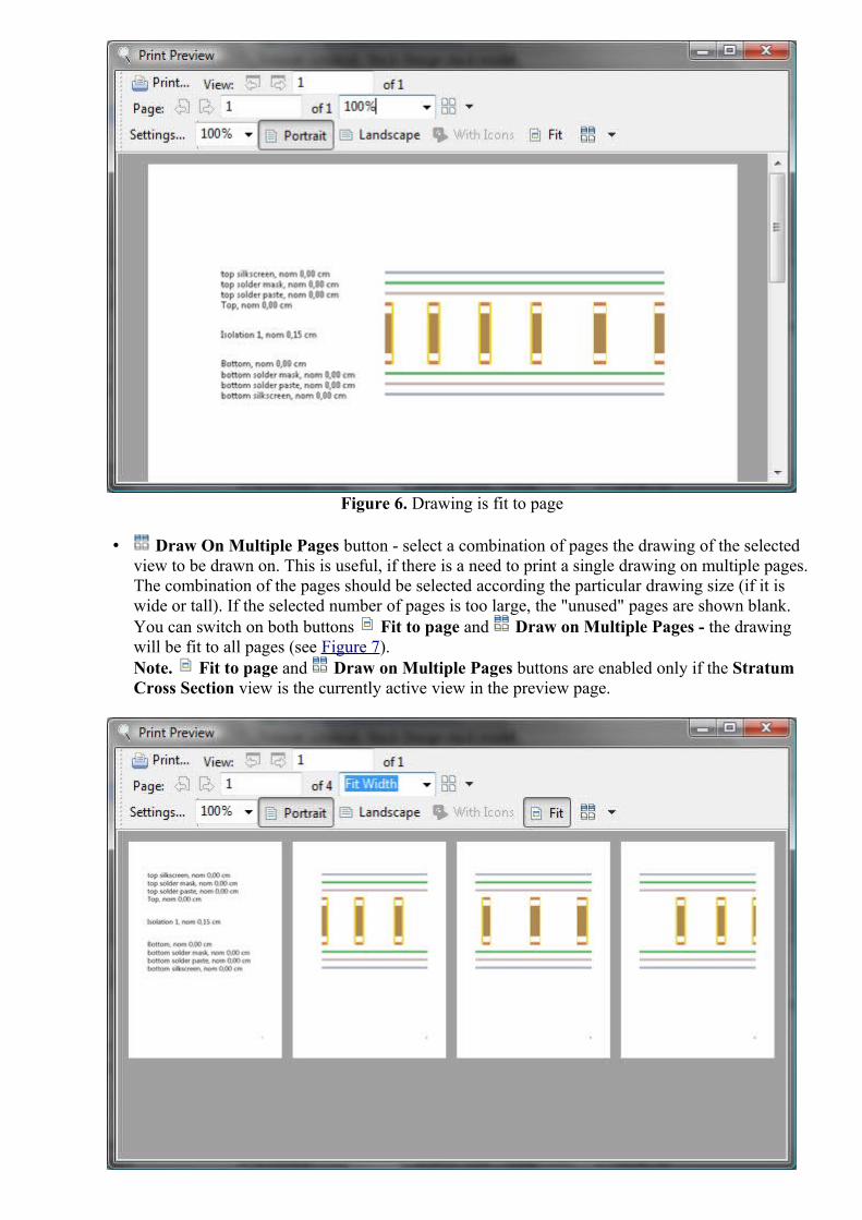
Figure 6. Drawing is fit to page
• Draw On Multiple Pages button - select a combination of pages the drawing of the selected view to be drawn on. This is useful, if there is a need to print a single drawing on multiple pages. The combination of the pages should be selected according the particular drawing size (if it is wide or tall). If the selected number of pages is too large, the "unused" pages are shown blank. You can switch on both buttons Fit to page and Draw on Multiple Pages - the drawing will be fit to all pages (see Figure 7). Note. Fit to page and Draw on Multiple Pages buttons are enabled only if the Stratum Cross Section view is the currently active view in the preview page.

Figure 7. Single drawing is fit to 4 pages
The settings, defined in the Print preview page are applied only for the current printing/previewing. After this page is closed - the manually defined settings are not saved.
To top
Copyright © 2009-2011 LKSoftWare GmbH. All Rights Reserved.JSDAI is a registered trade mark of LKSoftWare GmbH.
12.1. Reporting ErrorsIn case of an error condition please provide LKSoft with detailed information about the actual status of your IDA-STEP installation as described here:
1. Open Log view by selecting Window --> Show View --> Other --> General --> Log menu item.
• The Log view is activated on the screen. • Copy all content by using keyboard Ctrl+A, Ctrl+C or use a context sensitive menu (right
click + Select All, right click+Copy menu item). • Send the copied content to [email protected].
2. Select About IDA-STEP item in the Help menu. The About IDA-STEP dialog window appears (see Figure 1):
Figure 1. About IDA-STEP dialog window
• Click Configuration Details button. The Configuration Details window appears.

Figure 2. Configuration Details window
• Copy the content of the text box by using by Copy to Clipboard button. • Send the content to IDA-STEP developers.
• Click View Error log button. Select the text editor in the appeared dialog window. • Copy all content by using keyboard Ctrl+A, Ctrl+C or use a context sensitive menu
(right click + Select All, right click+Copy menu item) and send it to IDA-STEP developers.
• Close the window after you finish with the error report by using Close button. • Exit the About IDA-STEP dialog window by clicking OK button.
To top
Copyright © 2007-2009 LKSoftWare GmbH. All Rights Reserved.JSDAI is a registered trade mark of LKSoftWare GmbH.
12.2.1. Error: Insufficient disc space on drive C:While IDA-STEP installation is in progress, a message box with the following error appears: "Insufficient disc space on drive C:".
Cause
The installer requires about 100 megabytes of free disk space to expand in order to complete your IDA-STEP installation.
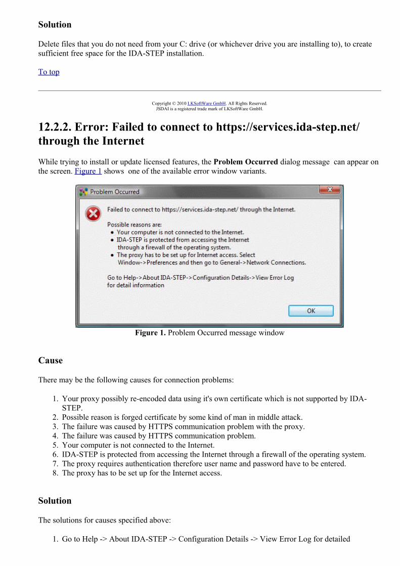
Solution
Delete files that you do not need from your C: drive (or whichever drive you are installing to), to create sufficient free space for the IDA-STEP installation.
To top
Copyright © 2010 LKSoftWare GmbH. All Rights Reserved.JSDAI is a registered trade mark of LKSoftWare GmbH.
12.2.2. Error: Failed to connect to https://services.ida-step.net/ through the InternetWhile trying to install or update licensed features, the Problem Occurred dialog message can appear on the screen. Figure 1 shows one of the available error window variants.
Figure 1. Problem Occurred message window
Cause
There may be the following causes for connection problems:
1. Your proxy possibly re-encoded data using it's own certificate which is not supported by IDA-STEP.
2. Possible reason is forged certificate by some kind of man in middle attack. 3. The failure was caused by HTTPS communication problem with the proxy. 4. The failure was caused by HTTPS communication problem. 5. Your computer is not connected to the Internet. 6. IDA-STEP is protected from accessing the Internet through a firewall of the operating system.7. The proxy requires authentication therefore user name and password have to be entered. 8. The proxy has to be set up for the Internet access.
Solution
The solutions for causes specified above:
1. Go to Help -> About IDA-STEP -> Configuration Details -> View Error Log for detailed

information. 2. Go to Help -> About IDA-STEP -> Configuration Details -> View Error Log for detailed
information. 3. Go to Help -> About IDA-STEP -> Configuration Details -> View Error Log for detailed
information. 4. Go to Help -> About IDA-STEP -> Configuration Details -> View Error Log for detailed
information. 5. Check your Internet connection, cable. 6. Change permission settings for a a firewall of the operating system. 7. Select Window->Preferences and then go to General->Network Connections. Enter a user
name and password in the Network Connections preferences page. 8. Select Window->Preferences and then go to General->Network Connections. Set up the proxy
for the Internet access.
If measures listed in the dialog box does not help, the user should go to Help -> About IDA-STEP -> Configuration Details -> View Error Log for detailed information and email the error log to IDA-STEP support (see Reporting errors).
To top
Copyright © 2009-2010 LKSoftWare GmbH. All Rights Reserved.JSDAI is a registered trade mark of LKSoftWare GmbH.
12.3.1. Error: License ID unknownAfter the license ID is entered in the Register, Update and Install dialog window New license ID field and the Next button is pressed, the Activation Failed message box with the error message 'License ID unknown' may appear on the screen (see Figure 1).
Figure 1. Activation failed dialog with error message "License ID unknown"
Cause
The license identifier is unknown.
Solution
Enter an available license ID or get a new one.
To top
Copyright © 2010 LKSoftWare GmbH. All Rights Reserved.

JSDAI is a registered trade mark of LKSoftWare GmbH.
12.3.2. Error: License is no longer validWhile updating IDA-STEP by using Register, Update and Install dialog window, the Activation Failed message window with the error message 'This license is no longer valid' may appear (see Figure 1).
Figure 1. Activation Failed message box with error message
Cause
The current license is no longer valid (blocked).
Solution
Get a new license to install IDA-STEP.
To top
Copyright © 2010 LKSoftWare GmbH. All Rights Reserved.JSDAI is a registered trade mark of LKSoftWare GmbH.
12.3.3. Error: No rehostings leftWhile the same license is used for the different computer, the error message window appears (see Figure 1):
Figure 1. Activation failed dialog with error message

Cause
IDA-STEP is licensed for a single computer.
Solution
Get a new license to install IDA-STEP on the different computer.
To top
Copyright © 2010 LKSoftWare GmbH. All Rights Reserved.JSDAI is a registered trade mark of LKSoftWare GmbH.
12.4. Internal errorThe Error message window is popped up on the screen (see Figure 1).
Figure 1. Error message window
Solution
Click on the hyper link http://www.ida-step.net/support/troubleshoot and follow instructions, presented in the How to report problems with IDA-STEP page. OrGo to Help -> About IDA-STEP -> Configuration Details -> View Error Log for detailed information and send by e-mail the error log to IDA-STEP support.
To top
Copyright © 2010-2011 LKSoftWare GmbH. All Rights Reserved.JSDAI is a registered trade mark of LKSoftWare GmbH.