5.23.1 + 5.23 - assets.gov.ie
TRANSCRIPT

2021(5) STEEL FRAME
INTRODUCTION
This section shows appropriate details for light steel frame construction. The Introduction document "Limiting Thermal Bridging and Air Infiltration Acceptable Construction Details" provides practical information with regards to implementation of these details onsite. This guide should be read in conjunction with these details. Details are given for junctions with a range of roof, ground floor and internal floor types, as well as at external wall opes.
The details within this section are valid for a range of steel frame wall thicknesses.
With steel frame, some insulation must be placed outside the frame to provide a thermal break and avoid condensation. Warm frame construction is
where all the insulation is outside the frame. Hybrid construction is where insulation is included both outside the steel structure and in between the
steel components. At least 33% of the thermal resistance should be provided outside the steel. Where compressible insulation is installed between studs
in addition to rigid board insulation over, it should be tightly packed and be in direct contact with the rigid board. Take care to ensure compressible
insulation is maintained above dewpoint temperature. With hybrid construction, the system manufacturer should provide a condensation risk analysis
(in accordance with Technical Guidance Document L, Appendix B) to ensure there is no risk of interstitial condensation. An internal vapour control layer is
generally required. The details show warm frame construction but apply equally to hybrid construction.
Insulation thicknesses have not been provided as these depend on the thermal properties of the materials chosen together with the proposed U-value. It is
important to choose appropriate tightly fitting materials. Generally, a rigid insulation material, which acts as an insulated sheathing board, is required
outside the frame.
Details show a masonry outer leaf for simplification. The details are also appropriate for a range of other claddings subject to suitable detailing. Further variables are insulation and sheathing types, and internal lining type and thickness. All external cladding systems should be "proper materials" as defined in
Part D.
These diagrams illustrate good practice for design and construction of interfaces only in respect to ensuring thermal performance and air barrier continuity. Other issues are not considered fully. The guidance must be implemented with due regard to all other Building Regulations requirements. All
materials and workmanship to be installed to Technical Guidance Document D "Materials and Workmanship."
Where these details are used for the Target U-values and constructions described in Table D5 of TGD L 2021 the psi values published in Table D5 may
be used to calculate the actual Thermal Bridging heat loss for the key thermal bridging junctions in that dwelling.
Technical Guidance Document B and Supplementary Guidance to TGD B provides guidance in relation to the provision of cavity barriers in air cavities, cavity barriers within combustible insulation layers and fire protection of structural elements.
The 2021 edition of the ACDs updates the drawings to take account of industry practice. The performance requirements remain the same as for the 2011 edition.

2021
This is an externally supported balcony (the balcony slab is
not a continuation of the floorslab) where the wall insulation
is continuous and not bridged by the balcony slab.
Value of Ψ is applied to each dwelling.
Where two building elements have one U-value above its
target while the other is below its target U-value, the
aggregate percentage change from the respective target
U-values in the table should not exceed +20% for the Psi (ψ)
value to be valid, i.e. if for the 0.15 U-value wall, if the U-value
was increased by 10% above the wall target U-value (from 0.15
to 0.165), then the roof U-value could be at most 10% below
the roof target U-value (from 0.14 to 0.126), because the
aggregate change would then be 20%.
ψ values for a Target U-value for the wall of 0.15 W/m²K can be
used for a range of U-values from of 0.12 W/m²K to 0.17
W/m²K for the construction type specified. The U-values of the
flanking elements to the wall can vary from the flanking element
target U-value as follows: Pitched roof insulation on slope,
insulation on ceiling 0.11 to 0.16 W/m²K; Flat Roof = 0.11 to
0.17 W/m²K; Ground Floor = 0.12 to 0.18W/m²K.
ψ values for a Target U-value for the wall of 0.21 W/m²K can
be used for a range of U-values down to 0.18 W/m²K for the
construction type specified. The U-values of the flanking
elements to the wall can vary from the flanking element target
U-value as follows: Pitched roof insulation on slope, insulation
on ceiling = 0.13 to 0.16 W/m²K;Flat Roof = 0.16 to 0.2 W/m²k;
Ground Floor = 0.16 to 0.21 W/m²K.
1.
2.
3.
4.
5.
(5) STEEL FRAME
5.09.2/5.10.2
5.11.2
5.20
Details
Table D5
Section 5
Section 5 - Steel Frame Construction
5.02
Junction detail
Identifier
5.01
5.06
5.03
Masonry Separating Wall Head – Section
6
5.05
5.04
5.13
Hybrid steel
5.07/5.08
5.11.1
5.12
5.14/5.15
5.16
5.17
5.19
5.18
ψ-value
5.21
Lightweight Intermediate Floor
5.23.1
5.22.1
5.22.2
5.23.2
Ground Floor - Insulation below slab
Ground Floor - Insulation above slab
(W/mK)
Separating Wall (section)
6
Separating Wall (plan)
6
Eaves – Unventilated/Ventilated Attic
Stud Partition Wall
5.09.1/5.10.1 Eaves – Unventilated/Ventilated – Insulation between and under rafters - Dormer
Eaves – Insulation between and over rafters – Unventilated rafter void
Eaves –Insulation between and under rafters – Unventilated/Ventilated void – Pitch
Ceiling Dormer
Eaves – Ventilated – Insulation between and under rafters – Pitched ceiling
Eaves – Ventilated – Insulation between and under rafters – Pitched with flat ceiling
Ventilated and Unventilated Attic
Gable – Insulation between and under rafters – Unventilated/Ventilated rafter void
Flat Roof – Eaves
Gable – Insulation between and over rafters – Unventilated rafter void
Flat Roof – Parapet
Ope – Sill
Ope – Lintel
Ope – Jamb
Steel Separating Wall through ground floor
Corner
Steel Partition Wall through ground floor
G.01.2
Inverted corner
Section G General Details
G.01.1
5.B.2
G.05.1
Other Details
5.B.1 Balcony within dwelling
4
0.038
Masonry Separating Wall Head – Section
6
Balcony between dwellings
4, 5
Solid Masonry Separating Wall through ground floor
6
Target U-values
= 0.18
1, 3
frame U-value
Junction detail (roof U = 0.16)
(floor U = 0.18)
0.033
0.021
0.114
0.141
0.103
0.520
0.026
0.013
0.00
0.030
0.032
0.014
0.011
0.020
0.007
0.111
0.049
0.055
0.054
0.093
0.006
0.023
0.012
0.213
0.125
0.075
-0.045
0.511
0.488
0.201
0.000
0.020
Hybrid steel
frame with
internal
insulation U-
value = 0.15
2, 3
(roof U = 0.14)
(floor U = 0.15)
ψ-value
(W/mK)
0.106
0.055
0.189
0.026
0.00
0.034
0.012
0.009
0.017
0.049
0.037
0.016
0.043
0.029
0.019
0.054
0.021
0.263
0.148
-0.043
0.484
0.458
0.000
0.240
0.020
Psi value is for whole junction. Half the value should be applied to
each dwelling on either side of the junction.
6.

Rigid insulation or board sheathing, or
Internal lining, for example, plasterboard, or
Airtightness membrane and tapes
Ground Floor - Insulation Above Slab
If sole plates are packed to level ensure that a continuous mortar grout is installed
Wall insulation installed below wall DPC must be fit for purpose as regards water absorption
Some thermal bridging is inevitable in this location since robust bearing and holding down
arrangements are normally required between frame and slab. Design should keep bridging
within acceptable limits to reduce condensation risk
Ensure wall insulation is installed at
least 225 mm below top of floor
Install edge insulation with min.
R-value of 0.75 m²K/W to perimeter
of floor screed
AIR BARRIER - OPTIONS
THERMAL PERFORMANCE
(5) STEEL FRAME
Complying with checklist will help achieve design air
permeability and may effect a reduced testing regime.
GENERAL NOTES
DETAIL 5.01, 2021
AIR BARRIER - CONTINUITY
CHECKLIST
(TICK ALL)
CHECKLIST
(TICK ALL)
OPTION
(TICK ONE)
22
5 m
m m
in
.
Seal all penetrations through air
barrier with suitable air tightness
tape, grommets or flexible sealant
Refer to Technical Guidance Document Part C for details on radon protection
Seal between wall and floor air
barriers with suitable airtightness
tape or a flexible sealant
An effective vapour control layer, which may serve as an air barrier, should be provided on
the warm side of the insulation in accordance with Appendix B of Technical Guidance
Document L
Ensure block with a maximum
Thermal Conductivity of 0.20 W/mK
in the direction of heat flow is used
beneath the steel framing to the
floor edge

Rigid insulation or board sheathing, or
Internal lining, for example, plasterboard, or
Airtightness membrane and tapes
Some thermal bridging is inevitable in this location since robust bearing and holding
down arrangements are normally required between frame and slab. Design should
keep bridging within acceptable limits to reduce condensation risk
Ensure wall insulation is installed at
least 225 mm below top of floor
Install edge insulation with min.
R-value of 1.09 m²K/W to perimeter
of floor slab
(5) STEEL FRAME
GENERAL NOTES
OPTION
(TICK ONE)
AIR BARRIER - OPTIONS
THERMAL PERFORMANCE
Complying with checklist will help achieve design air
permeability and may effect a reduced testing regime.
DETAIL 5.02, 2021
AIR BARRIER - CONTINUITY
CHECKLIST
(TICK ALL)
CHECKLIST
(TICK ALL)
Refer to Technical Guidance Document Part C for details on radon protection
Seal all penetrations through air
barrier with suitable air tightness
tape, grommets or flexible sealant
Seal between wall and floor air
barriers with suitable airtightness
tape or a flexible sealant
An effective vapour control layer, which may serve as an air barrier, should be
provided on the warm side of the insulation in accordance with Appendix B of
Technical Guidance Document L
Ground Floor - Insulation Below Slab
22
5 m
m m
in
.

Lightweight Intermediate Floor
Rigid insulation or board sheathing, or
Internal lining, for example, plasterboard, or
Airtightness membrane and tapes
GENERAL NOTES AIR BARRIER - OPTIONS
THERMAL PERFORMANCE
DETAIL 5.03, 2021
AIR BARRIER - CONTINUITY
CHECKLIST
(TICK ALL)
CHECKLIST
(TICK ALL)
(5) STEEL FRAME
OPTION
(TICK ONE)
Seal all penetrations through air
barrier with suitable air tightness
tape, grommets or flexible sealant
If using wall lining to form air barrier,
ensure air barrier continuity between
upper and lower wall linings. A
flexible membrane installed around
floor edge may be used to provide
this continuity. (Dotted blue line is
notional, to depict the air barrier
continuity through floor zone)
An effective vapour control layer, which may serve as an air barrier, should
be provided on the warm side of the insulation in accordance with
Appendix B of Technical Guidance Document L
Complying with checklist will help achieve design air
permeability and may effect a reduced testing regime.
Continue wall insulation across floor
abutment zone
Refer to Part B for fire safety requirements

Rigid insulation or board sheathing, or
Internal lining, for example, plasterboard, or
Airtightness membrane and tapes
Separating Wall (Plan)
GENERAL NOTES AIR BARRIER - OPTIONS
THERMAL PERFORMANCE
DETAIL 5.04, 2021
AIR BARRIER - CONTINUITY
CHECKLIST
(TICK ALL)
CHECKLIST
(TICK ALL)
(5) STEEL FRAME
OPTION
(TICK ONE)
Cavity to be stopped between the
ends of the separating wall and the
outer leaf with a flexible cavity
barrier
Ensure continuity of fire stopping
insulation between separating wall,
and external wall construction
Ensure air barrier continuity
between internal linings at corners
An effective vapour control layer, which may serve as an air barrier, should
be provided on the warm side of the insulation in accordance with
Appendix B of Technical Guidance Document L
Refer to Part E for resistance to sound requirements
Refer to Part B for fire safety requirements
Complying with checklist will help achieve design air
permeability and may effect a reduced testing regime.
Seal all penetrations through air
barrier with suitable air tightness
tape, grommets or flexible sealant
Read this detail in conjunction with detail 5.05, Separating Wall (Section)

Internal lining, for example, plasterboard, or
Airtightness membrane and tapes
GENERAL NOTES AIR BARRIER - OPTIONS
THERMAL PERFORMANCE
DETAIL 5.05, 2021
AIR BARRIER - CONTINUITY
CHECKLIST
(TICK ALL)
CHECKLIST
(TICK ALL)
(5) STEEL FRAME
OPTION
(TICK ONE)
Separating Wall (Section)
Spandrel panel above wall to be
insulated to at least the same height
as the top of attic insulation
Ensure full depth of insulation
between, over (or below) joists
extends to wall face
An effective vapour control layer, which may serve as an air barrier, should
be provided on the warm side of the insulation in accordance with
Appendix B of Technical Guidance Document L
Seal all penetrations through air
barrier with suitable air tightness
tape, grommets or flexible sealant
Ensure air barrier continuity
between ceiling and wall vapour
control layer/air barrier
Complying with checklist will help achieve design air
permeability and may effect a reduced testing regime.
Read this detail in conjunction with detail 5.04, Separating Wall (Plan)
Refer to Part E for resistance to sound requirements
Refer to Part B for fire safety requirements

Continue wall insulation across
abutment zone
Read this detail in conjunction with detail G.04, Metal Stud Partition
Head - Section
Rigid insulation or board sheathing, or
Internal lining, for example, plasterboard, or
Airtightness membrane and tapes
Stud Partition Wall (Plan)
GENERAL NOTES AIR BARRIER - OPTIONS
THERMAL PERFORMANCE
DETAIL 5.06, 2021
AIR BARRIER - CONTINUITY
CHECKLIST
(TICK ALL)
CHECKLIST
(TICK ALL)
(5) STEEL FRAME
Complying with checklist will help achieve design air
permeability and may effect a reduced testing regime.
Seal all penetrations through air
barrier with suitable air tightness
tape, grommets or flexible sealant
Ensure air barrier continuity through
partition wall zone
An effective vapour control layer, which may serve as an air barrier, should
be provided on the warm side of the insulation in accordance with
Appendix B of Technical Guidance Document L

Rigid insulation or board sheathing, or
Internal lining, for example, plasterboard, or
Airtightness membrane and tapes
Eaves - Unventilated Attic
Ensure continuity of insulation
throughout junction
GENERAL NOTES AIR BARRIER - OPTIONS
THERMAL PERFORMANCE
DETAIL 5.07, 2021
AIR BARRIER - CONTINUITY
CHECKLIST
(TICK ALL)
CHECKLIST
(TICK ALL)
(5) STEEL FRAME
Ensure full depth of insulation
between and over joists abuts eaves
insulation
Complying with checklist will help achieve design air
permeability and may effect a reduced testing regime.
Ensure gap between wall plate and
vapour permeable underlay is
completely filled with insulation
having a minimum R-value across the
insulation thickness of 4.50m²K/W
Eaves insulation must not hinder free water drainage below tiling battens
Use of over joist insulation eliminates the cold bridge caused by the joist
Read this detail in conjunction with detail 5.13, Gable - Ventilated and Unventilated Attic
Use vapour permeable roof underlay in accordance with third party certification
Refer to Technical Guidance Document B and Supplementary Guidance to TGD B for
guidance on cavity barriers and fire protection of structures
An effective vapour control layer, which may serve as an air barrier, should be provided on
the warm side of the insulation in accordance with Appendix B of Technical Guidance
Document L
Seal all penetrations through air
barrier with suitable air tightness
tape, grommets or flexible sealant
Ensure air barrier continuity
between ceiling and wall vapour
control layer/air barrier

Rigid insulation or board sheathing, or
Internal lining, for example, plasterboard, or
Airtightness membrane and tapes
Eaves - Ventilated Attic
Ensure continuity of insulation
throughout junction
Ensure full depth of insulation
between and over joists abuts eaves
insulation
Ensure gap between wall plate and
proprietary eaves vent is completely
filled with insulation having a
minimum R-value across the
insulation thickness of 4.50 m²K/W
(5) STEEL FRAME
GENERAL NOTES
OPTION
(TICK ONE)
AIR BARRIER - OPTIONS
THERMAL PERFORMANCE
Complying with checklist will help achieve design air
permeability and may effect a reduced testing regime.
DETAIL 5.08, 2021
AIR BARRIER - CONTINUITY
CHECKLIST
(TICK ALL)
CHECKLIST
(TICK ALL)
Seal all penetrations through air
barrier with suitable air tightness
tape, grommets or flexible sealant
Ensure air barrier continuity
between ceiling and wall vapour
control layer/air barrier
Use of over joist insulation eliminates the cold bridge caused by the joist
Read this detail in conjunction with detail 5.13, Gable - Ventilated and Unventilated Attic
An effective vapour control layer, which may serve as an air barrier, should be provided on
the warm side of the insulation in accordance with Appendix B of Technical Guidance
Document L
Refer to Technical Guidance Document B and Supplementary Guidance to TGD B for
guidance on cavity barriers and fire protection of structures
Use a proprietary eaves ventilator to ensure ventilation in accordance with Technical
Guidance Document F. Installation of eaves ventilator must not prevent free water drainage
below the tiling battens
Thermal performance of junction can be improved by incorporating an eaves wind barrier
(plywood, OSB, softboard or other suitable material)

Rigid insulation or board sheathing, or
Internal lining, for example, plasterboard, or
Airtightness membrane and tapes
Eaves - Insulation Between and Under Rafters -
Unventilated Rafter Void - Dormer
Eaves insulation must not hinder free water drainage below tiling battens
Ensure continuity of insulation
throughout junction
Ensure full depth of insulation
between and over joists abuts eaves
insulation
Ensure insulation is installed tightly
between rafters and is in contact
with under-rafter insulation
Ensure gap between wall plate and
vapour permeable underlay is
completely filled with insulation
having a minimum R-value across the
insulation thickness of 4.58 m²K/W
(5) STEEL FRAME
GENERAL NOTES
OPTION
(TICK ONE)
AIR BARRIER - OPTIONS
THERMAL PERFORMANCE
Complying with checklist will help achieve design air
permeability and may effect a reduced testing regime.
DETAIL 5.09.1 + 5.09.2, 2021
AIR BARRIER - CONTINUITY
CHECKLIST
(TICK ALL)
CHECKLIST
(TICK ALL)
5.09.2
Vapour permeable roof underlay to be used in accordance with approved third party certification
Use of over joist and under rafter insulation eliminates the cold bridge caused by the joist/rafter
An effective vapour control layer, which may serve as an air barrier, should be provided on the warm side
of the insulation in accordance with Appendix B of Technical Guidance Document L
Refer to Technical Guidance Document B and Supplementary Guidance to TGD B for guidance on cavity
barriers and fire protection of structures
Full-depth nogging installed between
ceiling joists to carry air barrier
through ceiling zone, sealed to air
barrier in roof with airtight tape
and/or flexible sealant
Seal all penetrations through air
barrier with suitable air tightness
tape, grommets or flexible sealant
Ensure air barrier continuity
between ceiling and wall vapour
control layer/air barrier
Read this detail in conjunction with details 5.13, Gable - Ventilated and Unventilated Attic and 5.14, Gable
- Insulation Between and Under Rafters - Unventilated Rafter Void
5.09.1

Rigid insulation or board sheathing, or
Internal lining, for example, plasterboard, or
Airtightness membrane and tapes
Eaves - Insulation Between and Under Rafters -
Ventilated Rafter Void - Dormer
(5) STEEL FRAME
GENERAL NOTES
OPTION
(TICK ONE)
AIR BARRIER - OPTIONS
THERMAL PERFORMANCE
Complying with checklist will help achieve design air
permeability and may effect a reduced testing regime.
DETAIL 5.10.1 + 5.10.2, 2021
AIR BARRIER - CONTINUITY
CHECKLIST
(TICK ALL)
CHECKLIST
(TICK ALL)
Ensure continuity of insulation
throughout junction
Ensure full depth of insulation
between and over joists abuts eaves
insulation
Ensure insulation is installed tightly
between rafters and is in contact
with under-rafter insulation
Ensure gap between wall plate and
proprietary eaves vent is completely
filled with insulation having a
minimum R-value across the
insulation thickness of 4.58 m²K/W
Seal all penetrations through air
barrier with suitable air tightness
tape, grommets or flexible sealant
Ensure air barrier continuity
between ceiling and wall vapour
control layer/air barrier
Full-depth nogging installed between
ceiling joists to carry air barrier
through ceiling zone , sealed to air
barrier in roof with airtight tape
and/or flexible sealant
Thermal performance of junction can be improved by incorporating an eaves wind barrier (plywood, OSB,
softboard or other suitable material)
Use of over joist and under rafter insulation eliminates the cold bridge caused by the joist/rafter
Use a proprietary eaves ventilator to ensure ventilation in accordance with Technical Guidance Document F.
Installation of the eaves ventilator must not prevent free water drainage below the tiling battens
An effective vapour control layer, which may serve as an air barrier, should be provided on the warm side
of the insulation in accordance with Appendix B of Technical Guidance Document L
Refer to Technical Guidance Document B and Supplementary Guidance to TGD B for guidance on cavity
barriers and fire protection of structures
5.10.1
5.10.2
Read this detail in conjunction with details 5.13, Gable - Ventilated and Unventilated Attic and 5.15, Gable
- Insulation Between and Under Rafters - Ventilated Rafter Void

Rigid insulation or board sheathing, or
Internal lining, for example, plasterboard, or
Airtightness membrane and tapes
Eaves - Insulation Between and Under Rafters -
Ventilated Rafter Void - Pitched ceiling
(5) STEEL FRAME
GENERAL NOTES
OPTION
(TICK ONE)
AIR BARRIER - OPTIONS
THERMAL PERFORMANCE
Complying with checklist will help achieve design air
permeability and may effect a reduced testing regime.
DETAIL 5.11.1 + 5.11.2, 2021
AIR BARRIER - CONTINUITY
CHECKLIST
(TICK ALL)
CHECKLIST
(TICK ALL)
An effective vapour control layer, which may serve as an air barrier, should be provided on the warm side
of the insulation in accordance with Appendix B of Technical Guidance Document L
Use a proprietary eaves ventilator to ensure ventilation in accordance with Technical Guidance Document F.
Installation of the eaves ventilator must not prevent free water drainage below the tiling battens
Read this detail in conjunction with details 5.13, Gable - Ventilated and Unventilated Attic and 5.15, Gable
- Insulation Between and Under Rafters - Ventilated Rafter Void
Thermal performance of junction can be improved by incorporating an eaves wind barrier (plywood, OSB,
softboard or other suitable material)
Use of over joist and under rafter insulation eliminates the cold bridge caused by the joist/rafter
Refer to Technical Guidance Document B and Supplementary Guidance to TGD B for guidance on cavity
barriers and fire protection of structures
Ensure full depth of insulation
between and over joists abuts eaves
insulation
Ensure continuity of insulation
throughout junction
Ensure gap between wall plate and
proprietary eaves vent is completely
filled with insulation having a
minimum R-value across the
insulation thickness of 4.70 m²K/W
Ensure insulation is installed tightly
between rafters and is in contact
with under-rafter insulation
Seal all penetrations through air
barrier with suitable air tightness
tape, grommets or flexible sealant
Ensure air barrier continuity
between ceiling and wall vapour
control layer/air barrier
5.11.1
5.11.2

Rigid insulation or board sheathing, or
Internal lining, for example, plasterboard, or
Airtightness membrane and tapes
Eaves - Insulation Between and Over Rafters -
Unventilated Rafter Void - Dormer
Read in conjunction with detail 5.16, Gable - Insulation Between and Over Rafters -
Unventilated Rafter Void
(5) STEEL FRAME
GENERAL NOTES
OPTION
(TICK ONE)
AIR BARRIER - OPTIONS
THERMAL PERFORMANCE
Complying with checklist will help achieve design air
permeability and may effect a reduced testing regime.
DETAIL 5.12, 2021
AIR BARRIER - CONTINUITY
CHECKLIST
(TICK ALL)
CHECKLIST
(TICK ALL)
Ensure continuity of insulation
throughout junction
Ensure full depth of insulation
between and over joists abuts eaves
insulation
Ensure insulation is installed tightly
between rafters and is in contact
with over-rafter insulation
Ensure gap between wall plate and
vapour permeable underlay is
completely filled with insulation
having a min. R-value across the
insulation thickness of 4.70 m²K/W
Full-depth nogging installed between
ceiling joists to carry air barrier
through ceiling zone , sealed to air
barrier in roof with airtight tape
and/or flexible sealant
Seal all penetrations through air
barrier with suitable air tightness
tape, grommets or flexible sealant
Ensure air barrier continuity
between ceiling and wall vapour
control layer/air barrier
Vapour permeable roof underlay to be used in accordance with approved third party
certification
Use of over joist and under rafter insulation eliminates the cold bridge caused by the
joist/rafter
An effective vapour control layer, which may serve as an air barrier, should be
provided on the warm side of the insulation in accordance with Appendix B of
Technical Guidance Document L
Refer to Technical Guidance Document B and Supplementary Guidance to TGD B for
guidance on cavity barriers and fire protection of structures

Rigid insulation or board sheathing, or
Internal lining, for example, plasterboard, or
Airtightness membrane and tapes
Gable - Ventilated and Unventilated Attic
Read in conjunction with details 5.07, Eaves - Unventilated Attic, or 5.08,
Eaves - Ventilated Attic, as appropriate
Use of over joist insulation eliminates the cold bridge caused by the joist
Pack compressible insulation
between last truss / joist, and gable
wall insulation
Ensure full depth of insulation between
and over joists extends to inner face of
rigid wall sheathing / insulation
(5) STEEL FRAME
GENERAL NOTES
OPTION
(TICK ONE)
AIR BARRIER - OPTIONS
THERMAL PERFORMANCE
Complying with checklist will help achieve design air
permeability and may effect a reduced testing regime.
DETAIL 5.13, 2021
AIR BARRIER - CONTINUITY
CHECKLIST
(TICK ALL)
CHECKLIST
(TICK ALL)
Seal all penetrations through air
barrier with suitable air tightness
tape, grommets or flexible sealant
Ensure air barrier continuity
between ceiling and wall vapour
control layer/air barrier
An effective vapour control layer, which may serve as an air barrier, should be
provided on the warm side of the insulation in accordance with Appendix B of
Technical Guidance Document L
Refer to Technical Guidance Document B and Supplementary Guidance to TGD B for
guidance on cavity barriers and fire protection of structures

Rigid insulation or board sheathing, or
Internal lining, for example, plasterboard, or
Airtightness membrane and tapes
Gable - Insulation Between and Under Rafters -
Unventilated Rafter Void
Read in conjunction with details 5.09, Eaves - Insulation Between and Under Rafters -
Unventilated Rafter Void
Ensure full depth of insulation between
and under rafters extends to wall.
Fit insulation over top of wall within
gable ladder with a minimum R-value
of 4.35 m²K/W
Ensure insulation continuity
throughout junction
Ensure wall insulation/cavity barrier is
taken up level with top of wall
Ensure insulation is installed tightly
between rafters and is in contact
with under-rafter insulation
(5) STEEL FRAME
GENERAL NOTES
OPTION
(TICK ONE)
AIR BARRIER - OPTIONS
THERMAL PERFORMANCE
Complying with checklist will help achieve design air
permeability and may effect a reduced testing regime.
DETAIL 5.14, 2021
AIR BARRIER - CONTINUITY
CHECKLIST
(TICK ALL)
CHECKLIST
(TICK ALL)
Eaves insulation must not hinder free water drainage below tiling battens
Vapour permeable roof underlay to be used in accordance with approved third party
certification
Use of over joist and under rafter insulation eliminates the cold bridge caused by the
joist/rafter
An effective vapour control layer, which may serve as an air barrier, should be provided on
the warm side of the insulation in accordance with Appendix B of Technical Guidance
Document L
Refer to Technical Guidance Document B and Supplementary Guidance to TGD B for
guidance on cavity barriers and fire protection of structures
Seal all penetrations through air
barrier with suitable air tightness
tape, grommets or flexible sealant
Ensure air barrier continuity
between ceiling and wall vapour
control layer/air barrier

Rigid insulation or board sheathing, or
Internal lining, for example, plasterboard, or
Airtightness membrane and tapes
Gable - Insulation Between and Under Rafters -
Ventilated Rafter Void
Read in conjunction with details 5.10, Eaves - Insulation Between and Under Rafters -
Ventilated Rafter Void
(5) STEEL FRAME
GENERAL NOTES
OPTION
(TICK ONE)
AIR BARRIER - OPTIONS
THERMAL PERFORMANCE
Complying with checklist will help achieve design air
permeability and may effect a reduced testing regime.
DETAIL 5.15, 2021
AIR BARRIER - CONTINUITY
CHECKLIST
(TICK ALL)
CHECKLIST
(TICK ALL)
Ensure full depth of insulation between
and under rafters extends to wall.
Ensure insulation continuity
throughout junction
Ensure wall insulation/cavity barrier is
taken up level with top of wall
Ensure insulation is installed tightly
between rafters and is in contact
with under-rafter insulation
Fit insulation over top of wall within
gable ladder with a minimum R-value
of 4.35 m²K/W
Maintain 50 mm ventilated void
above top of insulation
Use a proprietary eaves ventilator to ensure ventilation in accordance with Technical
Guidance Document F. Installation of the eaves ventilator must not prevent free water
drainage below the tiling battens
Use of over joist and under rafter insulation eliminates the cold bridge caused by the
joist/rafter
Refer to Technical Guidance Document B and Supplementary Guidance to TGD B for
guidance on cavity barriers and fire protection of structures
An effective vapour control layer, which may serve as an air barrier, should be provided on
the warm side of the insulation in accordance with Appendix B of Technical Guidance
Document L
Seal all penetrations through air
barrier with suitable air tightness
tape, grommets or flexible sealant
Ensure air barrier continuity
between ceiling and wall vapour
control layer/air barrier

Rigid insulation or board sheathing, or
Internal lining, for example, plasterboard, or
Airtightness membrane and tapes
Gable - Insulation Between and Over Rafters -
Unventilated Rafter Void
Read in conjunction with details 5.12, Eaves - Insulation Between and Over
Rafters - Unventilated Rafter Void
Fit insulation over top of wall within
gable ladder. Fully fill void between wall
head, and over-rafter insulation with a
minimum R-value of 2.17 m²K/W
Ensure insulation continuity
throughout junction
Ensure insulation is installed tightly
between rafters and is in contact
with over-rafter insulation
Ensure wall insulation/cavity barrier is
taken up level with top of wall
(5) STEEL FRAME
GENERAL NOTES
OPTION
(TICK ONE)
AIR BARRIER - OPTIONS
THERMAL PERFORMANCE
Complying with checklist will help achieve design air
permeability and may effect a reduced testing regime.
DETAIL 5.16, 2021
AIR BARRIER - CONTINUITY
CHECKLIST
(TICK ALL)
CHECKLIST
(TICK ALL)
Vapour permeable roof underlay to be used in accordance with approved third party
certification
Use of over joist and under rafter insulation eliminates the cold bridge caused by the
joist/rafter
An effective vapour control layer, which may serve as an air barrier, should be
provided on the warm side of the insulation in accordance with Appendix B of
Technical Guidance Document L
Refer to Technical Guidance Document B and Supplementary Guidance to TGD B for
guidance on cavity barriers and fire protection of structures
Seal all penetrations through air
barrier with suitable air tightness
tape, grommets or flexible sealant
Ensure air barrier continuity
between ceiling and wall vapour
control layer/air barrier
Rigid insulation or board sheathing, or
Internal lining, for example, plasterboard, or
Airtightness membrane and tapes
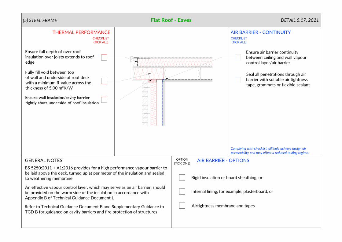
Flat Roof - Eaves
Ensure full depth of over roof
insulation over joists extends to roof
edge
Ensure wall insulation/cavity barrier
tightly abuts underside of roof insulation
(5) STEEL FRAME
GENERAL NOTES
OPTION
(TICK ONE)
AIR BARRIER - OPTIONS
THERMAL PERFORMANCE
Complying with checklist will help achieve design air
permeability and may effect a reduced testing regime.
DETAIL 5.17, 2021
AIR BARRIER - CONTINUITY
CHECKLIST
(TICK ALL)
CHECKLIST
(TICK ALL)
BS 5250:2011 + A1:2016 provides for a high performance vapour barrier to
be laid above the deck, turned up at perimeter of the insulation and sealed
to weathering membrane
An effective vapour control layer, which may serve as an air barrier, should
be provided on the warm side of the insulation in accordance with
Appendix B of Technical Guidance Document L
Refer to Technical Guidance Document B and Supplementary Guidance to
TGD B for guidance on cavity barriers and fire protection of structures
Seal all penetrations through air
barrier with suitable air tightness
tape, grommets or flexible sealant
Ensure air barrier continuity
between ceiling and wall vapour
control layer/air barrier
Fully fill void between top
of wall and underside of roof deck
with a minimum R-value across the
thickness of 5.00 m²K/W
Rigid insulation or board sheathing, or
Internal lining, for example, plasterboard, or
Airtightness membrane and tapes
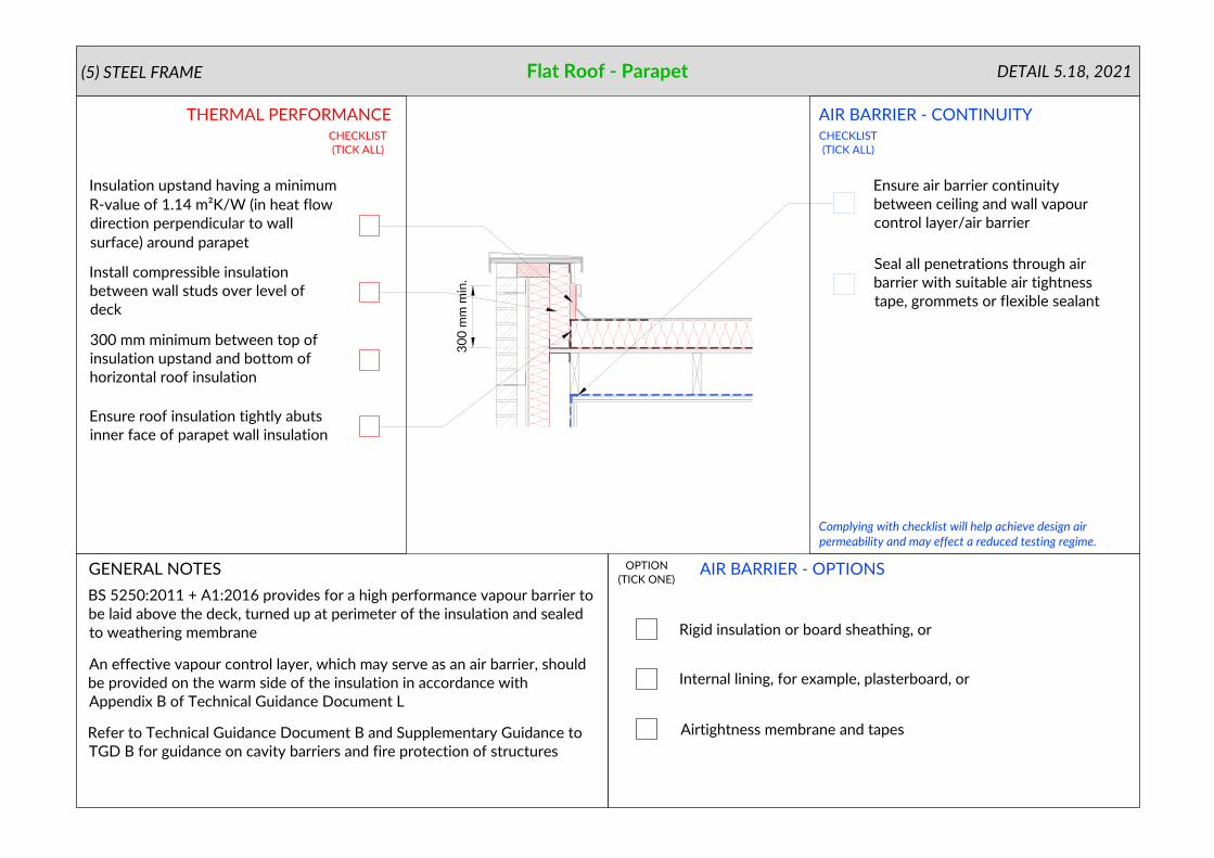
Flat Roof - Parapet
Install compressible insulation
between wall studs over level of
deck
Ensure roof insulation tightly abuts
inner face of parapet wall insulation
300 mm minimum between top of
insulation upstand and bottom of
horizontal roof insulation
Insulation upstand having a minimum
R-value of 1.14 m²K/W (in heat flow
direction perpendicular to wall
surface) around parapet
(5) STEEL FRAME
GENERAL NOTES
OPTION
(TICK ONE)
AIR BARRIER - OPTIONS
THERMAL PERFORMANCE
Complying with checklist will help achieve design air
permeability and may effect a reduced testing regime.
DETAIL 5.18, 2021
AIR BARRIER - CONTINUITY
CHECKLIST
(TICK ALL)
CHECKLIST
(TICK ALL)
30
0 m
m m
in
.
BS 5250:2011 + A1:2016 provides for a high performance vapour barrier to
be laid above the deck, turned up at perimeter of the insulation and sealed
to weathering membrane
An effective vapour control layer, which may serve as an air barrier, should
be provided on the warm side of the insulation in accordance with
Appendix B of Technical Guidance Document L
Refer to Technical Guidance Document B and Supplementary Guidance to
TGD B for guidance on cavity barriers and fire protection of structures
Seal all penetrations through air
barrier with suitable air tightness
tape, grommets or flexible sealant
Ensure air barrier continuity
between ceiling and wall vapour
control layer/air barrier

Rigid insulation or board sheathing, or
Internal lining, for example, plasterboard, or
Airtightness membrane and tapes
Install proprietary cavity closer with
thermal resistance path through
closer of 3.94 m²K/W or better
(Manufacturers' certified data)
Ope - Lintel
Ensure air barrier continuity
between window/door frame and
wall vapour control layer/air barrier
Finish insulation tight to cavity closer
(5) STEEL FRAME
GENERAL NOTES
OPTION
(TICK ONE)
AIR BARRIER - OPTIONS
THERMAL PERFORMANCE
Complying with checklist will help achieve design air
permeability and may effect a reduced testing regime.
DETAIL 5.19, 2021
AIR BARRIER - CONTINUITY
CHECKLIST
(TICK ALL)
CHECKLIST
(TICK ALL)
An effective vapour control layer, which may serve as an air barrier, should
be provided on the warm side of the insulation in accordance with
Appendix B of Technical Guidance Document L
Seal all penetrations through air
barrier with suitable air tightness
tape, grommets or flexible sealant

Rigid insulation or board sheathing, or
Internal lining, for example, plasterboard, or
Airtightness membrane and tapes
Ope - Jamb(5) STEEL FRAME
GENERAL NOTES
OPTION
(TICK ONE)
AIR BARRIER - OPTIONS
THERMAL PERFORMANCE
Complying with checklist will help achieve design air
permeability and may effect a reduced testing regime.
DETAIL 5.20, 2021
AIR BARRIER - CONTINUITY
CHECKLIST
(TICK ALL)
CHECKLIST
(TICK ALL)
Install proprietary cavity closer with
thermal resistance path through
closer of 3.94 m²K/W or better
(Manufacturers' certified data)
Ensure air barrier continuity
between window/door frame and
wall vapour control layer/air barrier
Finish insulation tight to cavity closer
Seal all penetrations through air
barrier with suitable air tightness
tape, grommets or flexible sealant
An effective vapour control layer, which may serve as an air barrier, should
be provided on the warm side of the insulation in accordance with
Appendix B of Technical Guidance Document L

Rigid insulation or board sheathing, or
Internal lining, for example, plasterboard, or
Airtightness membrane and tapes
(5) STEEL FRAME
GENERAL NOTES
OPTION
(TICK ONE)
AIR BARRIER - OPTIONS
THERMAL PERFORMANCE
Complying with checklist will help achieve design air
permeability and may effect a reduced testing regime.
DETAIL 5.21, 2021
AIR BARRIER - CONTINUITY
CHECKLIST
(TICK ALL)
CHECKLIST
(TICK ALL)
Install proprietary cavity closer with
thermal resistance path through
closer of 3.13 m²K/W or better
(Manufacturers' certified data)
Ensure air barrier continuity
between window/door frame and
wall vapour control layer/air barrier
Finish insulation tight to cavity closer
Seal all penetrations through air
barrier with suitable air tightness
tape, grommets or flexible sealant
An effective vapour control layer, which may serve as an air barrier, should
be provided on the warm side of the insulation in accordance with
Appendix B of Technical Guidance Document L

AIR BARRIER - OPTIONS
THERMAL PERFORMANCE
GENERAL NOTES
(TICK ALL)
CHECKLIST
(TICK ALL)
OPTION
(TICK ONE)
Rigid insulation or board sheathing, or
Internal lining, for example, plasterboard, or
Airtightness membrane and tapes
Complying with checklist will help achieve design air
permeability and may effect a reduced testing regime.
DETAIL 5.22.1, 2021
AIR BARRIER - CONTINUITY
CHECKLIST
(5) STEEL FRAMESteel Frame Separating Wall Through Ground Floor
Install edge insulation with min.
R-value of 1.09 m²K/W to perimeter
of floor slab
An effective vapour control layer, which may serve as an air barrier, should
be provided on the warm side of the insulation in accordance with
Appendix B of Technical Guidance Document L
Read this detail in conjunction with detail 5.02, Ground Floor - Insulation
Above Slab
Seal between wall and floor air
barriers with suitable airtightness
tape or a flexible sealant
Refer to Part E for resistance to sound requirements
Refer to Part B for fire safety requirements
Refer to Technical Guidance Document Part C for details on radon
protection

Corner / Inverted Corner
AIR BARRIER - OPTIONS
THERMAL PERFORMANCE
GENERAL NOTES
(TICK ALL)
CHECKLIST
(TICK ALL)
OPTION
(TICK ONE)
5.23.1
5.23.2
Rigid insulation or board sheathing, or
Internal lining, for example, plasterboard, or
Airtightness membrane and tapes
Complying with checklist will help achieve design air
permeability and may effect a reduced testing regime.
DETAIL 5.23.1 + 5.23.2, 2021
AIR BARRIER - CONTINUITY
CHECKLIST
(5) STEEL FRAME
Ensure insulation tightly abuts at
corners
An effective vapour control layer, which may serve as an air barrier, should
be provided on the warm side of the insulation in accordance with
Appendix B of Technical Guidance Document L
Seal all penetrations through air
barrier with suitable air tightness
tape, grommets or flexible sealant