528 na manual package (en) - tennant company · this manual is furnished with each new tennant...
TRANSCRIPT
528
MM193Rev. 08 (3–95)

This manual is furnished with each new TENNANT Model 528. It provides necessary operating and preventivemaintenance instructions. Read this manual completely and understand the machine before operating or servicing it.
This manual covers all machine variations and standard options. The instruction portion of the manual consists ofthe Specification, Operation, Maintenance, and Appendix sections. The parts portion consists of the Standard Model Parts; LPG Parts; Diesel Parts; SRS� Parts; Options; Miscellaneous Components; Hydraulic Components; Engine Parts, Gasoline, LPG; Engine Parts, DIS, Gasoline, LPG; Engine Parts, Diesel;and Cross Reference sections.
All right side and left side references to the machine are determined by facing the direction of forward travel. Allhardware considered to be of a common nature or locally available has been omitted from the parts sections. Beaware that this machine may contain metric hardware. Make sure you use equivalent hardware whenreplacement becomes necessary.
This machine will provide excellent service. However, the best results will be obtained at minimum costs if:
� The machine is operated with reasonable care.� The machine is maintained regularly – per the maintenance instructions provided.� The machine is maintained with Tennant Company supplied or equivalent parts.
Parts and supplies may be ordered by phone or mail from any Tennant Company parts and service center,distributor, or from any of the Tennant Company subsidiaries. Before ordering parts or supplies, be sure to haveyour machine model number and serial number handy. Fill out the data block below for future reference.
MACHINE DATA
Please fill out at time of installation.
Machine Serial Number –
Engine Serial Number –
Sales Representative –
Customer Number –
Date of Installation –
Manual Number – MM193
Revision: 08
Published: 3–95
Trademark Registered in: Austria, Benelux, Denmark, England, France, Germany, Italy, Spain, Switzerland,United States, Argentina, Australia, Canada, Japan, Mexico, Sweden, by TENNANT COMPANY, Minneapolis,Minnesota, U.S.A.
Acknowledgements: Technical information and/or illustrations supplied by Ford Motor Company; Kubota Ltd.;Cessna Fluid Power Division; Eaton Corporation, Hydraulics Division.
Copyright 1988, 1989, 1990, 1992, 1994, 1995 Tennant Company, Printed in U.S.A.

ABOUT THIS MANUAL
528 MM193 (2–92) �
ABOUT THIS MANUAL
The machine manual that you received with yourTENNANT machine contains valuable informationabout the operation and maintenance, andnumerous sections filled with TENNANT partnumbers for the repair of the machine. Pleaseread through this section titled ABOUT THISMANUAL to become familiar with the contents ofthe machine manual, making the information youare looking for easier to find.
The machine manual consists of several sectionsof reference information, and the remaindercontain part number information for orderingrepair parts for the machine. Each section has ashaded bar at the top of the page with the nameof that section. Just as this section has the titleABOUT THIS MANUAL on the top of each page.This way you can tell which section you are in atall times.
REFERENCE SECTIONS
The reference information sections of the manualare; General Information, Specifications,Operation, Maintenance, and Appendix.
GENERAL INFORMATION – The GeneralInformation section of the manual contains thesafety precautions, the location of the safetylabels on the machine, and a table of contents ofthe entire manual. The Safety Precautions are anoverview of the safety measures to be observedwhen operating and maintaining your machine.The location of the safety labels show themounting location of the safety labels for use inthe replacement of the labels. The table ofcontents in this section is a list of all the table ofcontents that appear in the front of each section inthe manual. This can be used for easy referenceto locate information in a particular section of themanual.
SPECIFICATIONS – The Specifications section ofthe manual contains machine specificationinformation useful in the operation andmaintenance of the machine. This section givesyou specification information on the engine,electric motors, brake system, hydraulics, fluidcapacities, and machine weight to mention a few.The section also has a illustration of the top andside view of the machine with the height and widthdimensions displayed.
OPERATION – The Operation section of themanual contains information needed to operatethe machine. This section will list the controls andinstruments on the machine, overview themachine operation, and tell you how to transportand store the machine.
MAINTENANCE – The Maintenance sectioncontains information on the suggestedmaintenance procedures and adjustments to keepyour machine in top operating condition. Thesection includes a Maintenance Chart listing themaintenance schedule and the areas of themachine to be addressed. Each subject ofmaintenance is covered in more detail in suchareas as Lubrication, Hydraulics, Engine, andElectrical System.
APPENDIX – The Appendix contains hardwareand hydraulic information. Standard hardwaretorques and identification information is included,plus hydraulic torques if your machine ishydraulically controlled.
PART SECTIONS
The remaining sections of the manual contain partnumber information for ordering repair parts foryour machine. The manual contains part numberinformation on every type of machine modelavailable in the model size of your particularmachine. Therefore there will be part numberinformation in your manual you will not need torefer to when wanting to place an order.
The main thing you need to know about yourmachine is what type of model is it. Is themachine powered by an engine or batteries? If themachine has an engine, is it fueled from gasoline,LPG, or diesel? If it is a mid-sized or largersweeper, is it multi-level or low dump? For thescrubbers, is it SRS� or standard. Determiningthis information about your machine will helpguide you through the separate parts sections tofind the repair part you need.

ABOUT THIS MANUAL
b 528 MM193 (2–92)
The smaller line of sweeper and scrubbers haveless complicated part section arrangement, andare easier to find your way through the partssections. The larger machines can have quite avariety of model types which significantlyincreases the size to the machine manual.Because of this, on the larger machine we madethe first part section, Section 5, a part sectionwhich contains parts common to all type of themachine. If the machine has an engine, thissection contains parts information on a gasolinepowered machine.
The remaining sections contain only partsinformation which is unique to that particularmachine type, such as unique diesel parts on themachine, or unique SRS� parts. Knowing themachine model type you have is important whensearching for that part information you need forordering repair parts. Start in that unique sectionfirst when looking for a part, then go to the firstparts section, Section 5, if the part can’t be foundin the unique section.
MACHINE SERIAL NUMBERS
When a design change takes place to a machine,the changes are indicated in the parts sectionswith machine serial numbers. Know the serialnumber of your machine which can be found onthe machine data plate mounted on the machine.Record this number on the inside front cover ofyour manual along with your customer number.
Machine number usage is recorded in theMachine Serial Number column of the parts listsin the parts sections of the manual. If the machineserial number column lists zeros on the left side ofthe dash, then this part is used on all machines;such as (000000– ).
If the column lists zeros on the left of the dashand a number on the right of the dash, then thepart is used on machines up to and including thatmachine serial number; such as (00000–002345).
For parts that are used on machines beginning atand continuing on from a certain serial number,the column would list a serial number on the left ofthe dash and have blank spaces on the right sideof the dash; such as (002346– ). This partwould be used on machines starting with thatmachine serial number and greater.
Finally, parts can be used on machines with serialnumbers in a certain block of numbers. In thissituation there is a serial number on the left andright side of the dash. The part is then used on amachine with a serial number starting at thenumber on the left and up to and including thenumber on the right; such as (002346–008900).
PARTS ASSEMBLIES
A part assembly has parts within the assembly,such as a parking brake consisting of othersmaller parts. What parts are contained in a partassembly can be determined by an indentationarrangement in the description column of theparts lists.
Here is an example of a part assembly, in thiscase we will use the parking brake mentionedpreviously:
MachineSerial Number Description Qty.(000000– ) Parking Brake 1(000000– ) Pin, Roll 1(000000– ) Link 1(000000– ) Spring, Compression 1(000000– ) Pin, Roll 1(000000– ) Support 1(000000– ) Lever, Release 1(000000– ) Rod, Parking Brake 1(000000– ) Washer, 0.50” 3
In this example, the parts whose descriptions areindented under the parking brake are all parts ofthe parking brake. When you order the parkingbrake you will receive all the parts listed under it.You also can order any of the individual partslisted under the parking brake if it is the only partyou need.

ABOUT THIS MANUAL
528 MM193 (9–92) �
SUPPLIER COMPONENT BREAKDOWNS
TENNANT purchases certain components of themachine from suppliers. Some of thesecomponents are engines, hydraulic pumps andmotors, electric motors, and solution pumps.
For those purchased components that arerepairable, lists of parts for them appear in thelater part of the parts sections. These are thesupplier breakdowns. The engine breakdowncontains both supplier and TENNANT partsnumbers for repair parts. Breakdowns forhydraulic and electrical components haveTENNANT part numbers for the parts TENNANTsupplies. The serial numbers listed in any of theparts lists in these sections is a serial number themanufacturer uses to identify design changes intheir particular component.
ORDERING REPAIR PARTS
Once you have located a part to order, there areseveral things you need to have to place theorder. At the beginning of each parts section is anOrdering Repair Parts page which lists theinformation you will need to place your order.Review this list before placing the order.

ABOUT THIS MANUAL
d 528 MM193 (9–92)

GENERAL INFORMATION
�528 MM193 (2–92)
SAFETY PRECAUTIONS
The following symbols are used throughout thismanual as indicated in their descriptions:
WARNING: To warn of hazards orunsafe practices which could result in
severe personal injury or death.
FOR SAFETY: To identify actions which mustbe followed for safe operation of equipment.
The following information signals potentiallydangerous conditions to the operator orequipment. Read this manual carefully. Knowwhen these conditions can exist. Locate all safetydevices on the machine. Then, take necessarysteps to train machine operating personnel.Report machine damage or faulty operationimmediately. Do not use the machine if it is not inproper operating condition.
FOR SAFETY:
1. Do Not Operate Machine:– Unless Trained And Authorized.– Unless Operation Manual Is Read And
Understood.– In Flammable Or Explosive Areas
Unless Designed For Use In ThoseAreas.
– In Areas With Possible Falling ObjectsUnless Equipped With OverheadGuard.
2. Before Starting Machine:– Check For Fuel Leaks.– Keep Sparks And Open Flame Away
From Refueling Area.– Make Sure All Safety Devices Are In
Place And Operate Properly.– Check Brakes And Steering For Proper
Operation.
3. When Starting Machine:– Keep Foot On Brake And Directional
Pedal In Neutral.
4. When Using Machine:– Use Brakes To Stop Machine.– Go Slow On Grades And Slippery
Surfaces.– Use Care When Backing Machine.– Do Not Carry Riders On Machine.– Always Follow Safety And Traffic
Rules.
5. Before Leaving Or Servicing Machine:– Stop On Level Surface.– Set Parking Brake.– Turn Off Machine And Remove Key.
6. When Servicing Machine:– Avoid Moving Parts. Do Not Wear
Loose Jackets, Shirts, Or SleevesWhen Working On Machine.
– Block Machine Tires Before JackingMachine Up.
– Jack Machine Up At DesignatedLocations Only. Block Machine UpWith Jack Stands.
– Use Hoist Or Jack Of AdequateCapacity To Lift Machine.
– Wear Eye And Ear Protection WhenUsing Pressurized Air Or Water.
– Disconnect Battery ConnectionsBefore Working On Machine.
– Avoid Contact With Battery Acid.– Avoid Contact With Hot Engine
Coolant.– Allow Engine To Cool.– Keep Flames And Sparks Away From
Fuel System Service Area. Keep AreaWell Ventilated.
– Use Cardboard To Locate LeakingHydraulic Fluid Under Pressure.
– Use TENNANT Supplied Or EquivalentReplacement Parts.
WARNING: Engine Emits Toxic Gases.Severe Respiratory Damage Or
Asphyxiation Can Result. Provide AdequateVentilation. Consult With Your RegulatoryAgency For Exposure Limits. Keep EngineProperly Tuned.
WARNING: Machine Can Emit ExcessiveNoise. Consult With Your Regulatory
Agency For Exposure Limits. Hearing LossCan Result. Wear Hearing Protection.
WARNING: Flammable Materials CanCause An Explosion Or Fire. Do Not
Use Flammable Materials In Tank(s).
WARNING: Flammable Materials OrReactive Metals Can Cause Explosion
Or Fire. Do Not Pick Up.
WARNING: Moving Fan Blades. KeepAway.
GENERAL INFORMATION
528 MM193 (3–95)��
WARNING: Strong Vacuum. Keep AwayFrom Fan Inlet When Fan Is Running.
WARNING: Heavy Bumper. Get Help toHandle.

GENERAL INFORMATION
���528 MM193 (6–94)
The following safety labels are mounted on themachine in the locations indicated. If these or anylabel becomes damaged or illegible, install a newlabel in its place.
SAFETY LABEL –LOCATED ON THE DRIVERCOMPARTMENT PANEL.
04412
04761
04760
ENGINE FAN LABEL – LOCATEDON ENGINE FAN SHROUD
VACUUM FAN LABEL –LOCATED ON THEVACUUM FAN HOUSING.
NO GASOLINE LABEL – LOCATEDON THE REAR DECK OF THEMACHINE.
EMISSIONS LABEL – LOCATED ONTHE DRIVER COMPARTMENT PANEL.
04750
NOISE LABEL – LOCATED ONTHE DRIVER COMPARTMENTPANEL.
HEAVY BUMPER – LOCATED ONTHE SCRUB HEAD COVER SIDES.

GENERAL INFORMATION
528 MM193 (3–95)��
CONTENTS
PageGENERAL INFORMATION i. . . . . . . . . . . . . .
SAFETY PRECAUTIONS i. . . . . . . . . . .
SPECIFICATIONS 1-1. . . . . . . . . . . . . . . . . . . . . MACHINE SPECIFICATIONS 1-3. . . . . . . .
POWER TYPE 1-3. . . . . . . . . . . . . . . . . . POWER TRAIN 1-3. . . . . . . . . . . . . . . . . STEERING 1-3. . . . . . . . . . . . . . . . . . . . . HYDRAULIC SYSTEM 1-3. . . . . . . . . . . BRAKING SYSTEM 1-3. . . . . . . . . . . . . SUSPENSION SYSTEM 1-4. . . . . . . . . SYSTEM FLUID CAPACITIES 1-4. . . . GENERAL MACHINE
DIMENSIONS/CAPACITIES 1-4. . . MACHINE WEIGHTS 1-4. . . . . . . . . . . . GENERAL MACHINE PERFORMANCE 1-4
MACHINE DIMENSIONS 1-5. . . . . . . . . . . .
OPERATION 2-1. . . . . . . . . . . . . . . . . . . . . . . . . . PREPARATION FOR OPERATION 2-3. . .
AFTER UNLOADING AND BEFORE OPERATING THE MACHINE: 2-3. .
OPERATION OF CONTROLS 2-4. . . . . . . MACHINE COMPONENTS 2-4. . . . . . . INSTRUMENT PANEL SYMBOLS 2-5. INSTRUMENTS AND CONTROLS 2-6BRAKE PEDAL 2-7. . . . . . . . . . . . . . . . . DIRECTIONAL PEDAL 2-7. . . . . . . . . . . PARKING BRAKE LEVER 2-7. . . . . . . . OPERATOR SEAT 2-7. . . . . . . . . . . . . . . SEAT BELT 2-7. . . . . . . . . . . . . . . . . . . . . SOLUTION FLOW LEVER – MAIN
BRUSHES 2-7. . . . . . . . . . . . . . . . . . . SOLUTION FLOW LEVER – SIDE
BRUSH 2-7. . . . . . . . . . . . . . . . . . . . . SRS� LAMP 2-7. . . . . . . . . . . . . . . . . . . . CLEANING SOLUTION
FLOW SWITCH 2-8. . . . . . . . . . . . . . THROTTLE SWITCH 2-8. . . . . . . . . . . . CLEANING SWITCH 2-8. . . . . . . . . . . . . SCRUB HEAD SWITCH 2-8. . . . . . . . . . SIDE BRUSH SWITCH 2-8. . . . . . . . . . . OPERATIONAL LAMPS SWITCH 2-8. SOLUTION TANK LOW LAMP 2-8. . . . RECOVERY TANK FULL LAMP 2-8. . . IGNITION SWITCH 2-9. . . . . . . . . . . . . . HOUR METER 2-9. . . . . . . . . . . . . . . . . . VOLTAGE GAUGE 2-9. . . . . . . . . . . . . . ENGINE COOLANT TEMPERATURE
GAUGE 2-9. . . . . . . . . . . . . . . . . . . . . ENGINE OIL PRESSURE GAUGE 2-9CIRCUIT BREAKERS 2-9. . . . . . . . . . . . STEERING WHEEL 2-9. . . . . . . . . . . . . FUEL LEVEL GAUGE 2-10. . . . . . . . . . . .
PageENGINE CHOKE KNOB 2-10. . . . . . . . . . DIESEL PREHEAT PUSH BUTTON 2-10DIESEL THROTTLE KNOB 2-10. . . . . . .
MACHINE OPERATION 2-11. . . . . . . . . . . . . NORMAL SCRUBBING OPERATION 2-11
PRE–START CHECKLIST 2-11. . . . . TO START MACHINE 2-11. . . . . . . . . TO FILL SOLUTION TANK 2-12. . . . . TO SCRUB 2-13. . . . . . . . . . . . . . . . . . TO DRAIN RECOVERY TANK AND
EMPTY HOPPER 2-13. . . . . . . . . . POST OPERATION CHECKLIST –
ENGINE OPERATING 2-14. . . . . . TO STOP MACHINE 2-14. . . . . . . . . . POST OPERATION CHECKLIST –
ENGINE STOPPED 2-15. . . . . . . . DOUBLE SCRUBBING OPERATION 2-15OPERATION ON GRADES 2-15. . . . . . . SOLUTION TANK 2-16. . . . . . . . . . . . . . . DETERGENT RECOMMENDATIONS 2-16RECOVERY TANK 2-16. . . . . . . . . . . . . . DEBRIS HOPPER 2-17. . . . . . . . . . . . . . . SRS� CLEANING SOLUTION TANK 2-17SRS� SOLUTION TANK 2-18. . . . . . . . . . MACHINE TROUBLESHOOTING 2-19.
OPTIONS OPERATION 2-21. . . . . . . . . . . . . VACUUM WAND 2-21. . . . . . . . . . . . . . . .
TO OPERATE VACUUM WAND 2-21TRANSPORTING MACHINE 2-22. . . . . . . . .
PUSHING OR TOWING MACHINE 2-22MACHINE JACKING 2-22. . . . . . . . . . . . .
TO JACK UP MACHINE 2-22. . . . . . . MACHINE TIE–DOWNS 2-23. . . . . . . . . .
MACHINE STORAGE 2-24. . . . . . . . . . . . . . . STORING MACHINE 2-24. . . . . . . . . . . .
MAINTENANCE 3-1. . . . . . . . . . . . . . . . . . . . . . . . . RECOMMENDED FIRST 50–HOUR
MACHINE INSPECTION 3-3. . . . . . . . . . . . MAINTENANCE CHART 3-4. . . . . . . . . . . . LUBRICATION 3-6. . . . . . . . . . . . . . . . . . . . .
ENGINE 3-6. . . . . . . . . . . . . . . . . . . . . . . . GASOLINE AND LPG POWERED
ENGINES 3-6. . . . . . . . . . . . . . . . . DIESEL POWERED ENGINES 3-6.
REAR SQUEEGEE ROLLER (For machines below serial number 033056) 3-6. . . . . . . . .
SCRUB HEAD PIVOTS 3-7. . . . . . . . . . FRONT CASTER AND
WHEEL BEARING 3-7. . . . . . . . . . . . STEERING ARM ROD ENDS 3-8. . . . . STEERING GEAR 3-8. . . . . . . . . . . . . . .

GENERAL INFORMATION
�528 MM193 (2–92)
PageHYDRAULICS 3-9. . . . . . . . . . . . . . . . . . . . .
HYDRAULIC FLUID 3-9. . . . . . . . . . . . . HYDRAULIC FLUID RESERVOIR 3-9.
TO DRAIN THE HYDRAULIC FLUID RESERVOIR 3-10. . . . . . . . . . . . . .
TO FILL THE HYDRAULIC FLUID RESERVOIR 3-10. . . . . . . . . . . . . .
HYDRAULIC FLUID RESERVOIR BREATHER 3-11. . . . . . . . . . . . . . . . . .
HYDRAULIC FLUID FILTER 3-11. . . . . . TO REPLACE HYDRAULIC FLUID
FILTER ELEMENT 3-11. . . . . . . . . HYDRAULIC PUMPS 3-12. . . . . . . . . . . .
TO START AND BREAK–IN HYDRAULIC PUMP 3-12. . . . . . . .
DIRECTIONAL PEDAL 3-12. . . . . . . . . . . TO ADJUST DIRECTIONAL
CONTROL PEDAL LINKAGE 3-13HYDRAULIC FLUID LEAKS 3-13. . . . . . HYDRAULIC SYSTEM
TROUBLESHOOTING 3-14. . . . . . . . HYDRAULIC COMPONENTS
TROUBLESHOOTING 3-17. . . . . . . . HYDRAULIC SCHEMATIC (For machines
below serial number 030366) 3-18. . . HYDRAULIC SCHEMATIC, WITH SIDE
BRUSH OPTION (For machines below serial number 030366) 3-19. . .
HYDRAULIC SCHEMATIC (For machines serial number 030366 and above) 3-20
HYDRAULIC SCHEMATIC, WITH SIDE BRUSH OPTION (For machines serial number 030366 and above) 3-21. . . .
ENGINE 3-22. . . . . . . . . . . . . . . . . . . . . . . . . . ENGINE LUBRICATION 3-22. . . . . . . . . .
GASOLINE AND LPG POWERED ENGINES 3-22. . . . . . . . . . . . . . . . .
DIESEL POWERED ENGINES 3-22. COOLING SYSTEM 3-22. . . . . . . . . . . . . AIR INTAKE SYSTEM 3-23. . . . . . . . . . .
AIR FILTER RESTRICTION INDICATOR 3-23. . . . . . . . . . . . . . .
AIR FILTER 3-23. . . . . . . . . . . . . . . . . . TO REPLACE AIR
FILTER ELEMENT 3-24. . . . . . . . . FUEL SYSTEM – GASOLINE 3-25. . . . .
FUEL FILTER 3-25. . . . . . . . . . . . . . . . CARBURETOR 3-25. . . . . . . . . . . . . . .
FUEL SYSTEM – LPG 3-26. . . . . . . . . . . LPG FUEL SYSTEM 3-26. . . . . . . . . . FUEL TANKS 3-27. . . . . . . . . . . . . . . . TO CHANGE AN LPG
FUEL TANK 3-27. . . . . . . . . . . . . . . FUEL FILTER LOCK 3-28. . . . . . . . . . VAPORIZER–REGULATOR 3-28. . . . CARBURETOR 3-28. . . . . . . . . . . . . . . OIL PRESSURE SWITCH 3-28. . . . . LPG FUEL TROUBLESHOOTING 3-29
PageFUEL SYSTEM – DIESEL 3-30. . . . . . . .
DIESEL FUEL SYSTEM 3-30. . . . . . . FUEL WATER TRAP FILTER 3-30. . . TO REPLACE FUEL FILTER
ELEMENT 3-30. . . . . . . . . . . . . . . . PRIMING FUEL SYSTEM 3-30. . . . . TO PRIME FUEL SYSTEM 3-31. . . .
GOVERNOR – GASOLINE, LPG 3-31. . IGNITION SYSTEM –
GASOLINE, LPG 3-31SPARK PLUGS 3-31. . . . . . . . . . . . . . DISTRIBUTOR (For machines below
serial number 031000) 3-32. . . . . . ENGINE IGNITION TIMING
(For machines below serial number 031000) 3-32. . . . . . . . . . .
TO CHECK AND ADJUST IGNITION TIMING (For machines below serial number 031000) 3-32. . . . . .
ENGINE IGNITION TIMING (For machines serial number 031000 and above) 3-33. . . . . . . . .
CYLINDER HEAD – GASOLINE, LPG 3-33. . . . . . . . . . . . . CYLINDER HEAD 3-33. . . . . . . . . . . . VALVE TAPPET CLEARANCE 3-34.
CYLINDER HEAD – DIESEL 3-34. . . . . . CYLINDER HEAD 3-34. . . . . . . . . . . . VALVE CLEARANCE 3-34. . . . . . . . . .
CRANKCASE VENTILATION SYSTEM 3-34. . . . . . . . . . . . . . . . . . . .
TUNE–UP CHART – GASOLINE, LPG 3-34. . . . . . . . . . . . .
ELECTRICAL SYSTEM 3-35. . . . . . . . . . . . . BATTERY 3-35. . . . . . . . . . . . . . . . . . . . . . . . ELECTRICAL SCHEMATIC,
GASOLINE, LPG (For machines below serial number 031000) 3-36. . .
ELECTRICAL SCHEMATIC, GASOLINE, LPG (For machines serial number 031000 and above) 3-38
ELECTRICAL SCHEMATIC, DIESEL 3-40BELTS AND CHAINS 3-42. . . . . . . . . . . . . . .
ENGINE FAN BELT 3-42. . . . . . . . . . . . . . STATIC DRAG CHAIN 3-42. . . . . . . . . . .
SCRUB HEAD 3-43. . . . . . . . . . . . . . . . . . . . . SCRUB HEAD 3-43. . . . . . . . . . . . . . . . . .
TO LEVEL SCRUB HEAD 3-43. . . . . BRUSHES 3-46. . . . . . . . . . . . . . . . . . . . . . . . .
MAIN BRUSHES 3-46. . . . . . . . . . . . . . . . TO REPLACE MAIN BRUSHES 3-46TO CHECK AND ADJUST MAIN
BRUSH PATTERN 3-48. . . . . . . . . SIDE BRUSH 3-50. . . . . . . . . . . . . . . . . . .
TO REMOVE SIDE BRUSH 3-50. . . . TO INSTALL SIDE BRUSH 3-50. . . . TO ADJUST DOWN PRESSURE 3-51

GENERAL INFORMATION
528 MM193 (2–92)��
PageSQUEEGEES 3-52. . . . . . . . . . . . . . . . . . . . . . . .
SIDE SQUEEGEES 3-52. . . . . . . . . . . . . TO REPLACE SIDE SQUEEGEE
BLADES 3-52. . . . . . . . . . . . . . . . . . TO ADJUST SIDE SQUEEGEES 3-52
SIDE SQUEEGEE LATCHES 3-53. . . . . REAR SQUEEGEE 3-53. . . . . . . . . . . . . .
TO REPLACE OR ROTATE REAR BLADE 3-53. . . . . . . . . . . . . . . . . . .
TO REPLACE FRONT BLADE 3-54. TO ADJUST REAR SQUEEGEE 3-55
REAR SQUEEGEE RETAINING BAND CLAMPS 3-56. . . . . . . . . . . . . .
SIDE BRUSH SQUEEGEE 3-56. . . . . . . TO REPLACE SIDE BRUSH
SQUEEGEE 3-56. . . . . . . . . . . . . . SOLUTION AND RECOVERY TANKS 3-58
SOLUTION TANK 3-58. . . . . . . . . . . . . . . SOLUTION VALVE(S) 3-58. . . . . . . . . . . . SOLUTION SPREADER TUBE 3-58. . . . RECOVERY TANK 3-59. . . . . . . . . . . . . . DEBRIS HOPPER 3-60. . . . . . . . . . . . . . . SRS� SOLUTION TANK 3-60. . . . . . . . . . SRS� SOLUTION SPRAY NOZZLE 3-62
BRAKES AND TIRES 3-63. . . . . . . . . . . . . . . SERVICE BRAKES 3-63. . . . . . . . . . . . . .
TO BLEED BRAKES 3-63. . . . . . . . . . PARKING BRAKES 3-63. . . . . . . . . . . . . . TIRES 3-63. . . . . . . . . . . . . . . . . . . . . . . . .
APPENDIX 4-1. . . . . . . . . . . . . . . . . . . . . . . . . . . . HARDWARE INFORMATION 4-3. . . . . . . .
STANDARD BOLT TORQUE CHART 4-3METRIC BOLT TORQUE CHART 4-3. BOLT IDENTIFICATION 4-3. . . . . . . . . . THREAD SEALANT AND
LOCKING COMPOUNDS 4-3. . . . . . HYDRAULIC FITTING INFORMATION 4-4
HYDRAULIC TAPERED PIPE FITTING (NPT) TORQUE CHART 4-4. . . . . . .
HYDRAULIC TAPERED SEAT FITTING (JIC) TORQUE CHART 4-4. . . . . . . .
HYDRAULIC O–RING FITTING TORQUE CHART 4-4. . . . . . . . . . . . . . . . . . . . . .
STANDARD MODEL PARTS 5-1. . . . . . . . . . . . ORDERING REPAIR PARTS 5-3. . . . . . . . Fig. 1 – Recommended General
Maintenance Items 5-4. . . . . . Fig. 2 – Replacement Brushes 5-5. . . . . . . Fig. 3 – Main Frame Group 5-6. . . . . . . . . . Fig. 4 – Engine Hood Group 5-8. . . . . . . . . Fig. 5 – Overhead Guard Group 5-9. . . . . Fig. 6 – Seat Group 5-10. . . . . . . . . . . . . . . . Fig. 7 – Brake Pedal and Cylinder Group 5-11
PageFig. 8 – Directional Pedal Group 5-12. . . . . Fig. 9 – Right Side Brake Group 5-14. . . . . Fig. 10 – Left Side Brake Group 5-16. . . . . . Fig. 11 – Drive Motors Group 5-18. . . . . . . . . Fig. 12 – Pump Group 5-19. . . . . . . . . . . . . . . Fig. 13 – Engine Flywheel and
Mount Group 5-20. . . . . . . . . . . Fig. 14 – Engine Group 5-21. . . . . . . . . . . . . . Fig. 15 – Engine Group,
Distributorless (DIS) 5-22. . . . . Fig. 16 – Carburetor Group 5-24. . . . . . . . . . Fig. 17 – Carburetor Group,
Distributorless (DIS) 5-26. . . . . Fig. 18 – Air Cleaner Group 5-28. . . . . . . . . . Fig. 19 – Engine Fan and
Alternator Group 5-30. . . . . . . . Fig. 20 – Radiator Group 5-32. . . . . . . . . . . . Fig. 21 – Radiator Group,
Distributorless (DIS) 5-34. . . . . Fig. 22 – Muffler Group 5-36. . . . . . . . . . . . . . Fig. 23 – Muffler Group,
Distributorless (DIS) 5-37. . . . . Fig. 24 – Muffler Group,
Distributorless (DIS) 5-38. . . . . Fig. 25 – Battery Group 5-39. . . . . . . . . . . . . Fig. 26 – Fuel Tank and Shrouds Group 5-40Fig. 27 – Fuel Tank and Shrouds Group 5-42Fig. 28 – Steering Column Assembly 5-44. . Fig. 29 – Front Instrument Panel Group 5-46Fig. 30 – Side Instrument Panel Group 5-47Fig. 31 – Wire Harness Group 5-48. . . . . . . . Fig. 32 – Wire Harness Group,
Distributorless (DIS) 5-50. . . . . Fig. 33 – Solution Supply Group 5-52. . . . . . Fig. 34 – Vacuum Fan Assembly 5-53. . . . . Fig. 35 – Solution and Recovery
Tank Group 5-54. . . . . . . . . . . . Fig. 36 – Hydraulic Hose Group 5-56. . . . . . Fig. 37 – Hydraulic Reservoir Group 5-58. . Fig. 38 – Front Solenoid Valve Group 5-59. Fig. 39 – Scrub Head Frame Group 5-60. . . Fig. 40 – Scrub Head Lift Group 5-62. . . . . . Fig. 41 – Scrub Head Cover Group 5-64. . . Fig. 42 – Pick–Up Trough Assembly 5-65. . Fig. 43 – Rear Hydraulic Solenoid
Valve Group 5-66. . . . . . . . . . . . Fig. 44 – Rear Hydraulic Solenoid
Valve Group 5-67. . . . . . . . . . . . Fig. 45 – Brush Drive Motor Group 5-68. . . . Fig. 46 – Label Group 5-69. . . . . . . . . . . . . . . Fig. 47 – Left Side Squeegee Assembly 5-70Fig. 48 – Right Side Squeegee Assembly 5-71Fig. 49 – Rear Squeegee Assembly 5-72. . .

GENERAL INFORMATION
���528 MM193 (3–95)
PageLPG PARTS 6-1. . . . . . . . . . . . . . . . . . . . . . . . . . .
ORDERING REPAIR PARTS 6-3. . . . . . . . Fig. 1 – Engine Group, LPG 6-4. . . . . . . . . Fig. 2 – Engine Group,
Distributorless (DIS), LPG 6-6Fig. 3 – Fuel Tank Group, LPG 6-8. . . . . .
DIESEL PARTS 7-1. . . . . . . . . . . . . . . . . . . . . . . . ORDERING REPAIR PARTS 7-3. . . . . . . . Fig. 1 – Engine Group, Diesel 7-4. . . . . . . . Fig. 2 – Engine Fuel Line Group, Diesel 7-6Fig. 3 – Fuel Tank Group, Diesel 7-8. . . . . . Fig. 4 – Radiator Group, Diesel 7-10. . . . . . . Fig. 5 – Throttle Linkage Group, Diesel 7-11Fig. 6 – Alternator Group, Diesel 7-12. . . . . . Fig. 7 – Muffler Group, Diesel 7-14. . . . . . . . Fig. 8 – Battery Group, Diesel 7-15. . . . . . . . Fig. 9 – Wire Harness Group, Diesel 7-16. . Fig. 10 – Instrument Panel Group, Diesel 7-18Fig. 11 – Foam Insulation Group 7-19. . . . . .
SRS� MODEL PARTS 8-1. . . . . . . . . . . . . . . . . . ORDERING REPAIR PARTS 8-3. . . . . . . . Fig. 1 – Solution Supply Group, SRS� 8-4Fig. 2 – Solution Tank Group, SRS� 8-6. . Fig. 3 – Instrument Panel Group, SRS� 8-8
OPTIONS 9-1. . . . . . . . . . . . . . . . . . . . . . . . . . . . . . . ORDERING REPAIR PARTS 9-3. . . . . . . . Fig. 1 – Flashing Light Kit 9-4. . . . . . . . . . . Fig. 2 – Revolving Light Kit 9-5. . . . . . . . . . Fig. 3 – Headlight and Taillight Kit 9-6. . . . Fig. 4 – Side Guard Group 9-7. . . . . . . . . . Fig. 5 – Fuel Gauge Kit 9-8. . . . . . . . . . . . . Fig. 6 – Protectoseal Fuel Tank Cap Kit 9-8Fig. 7 – Level Sensing Plug Group 9-9. . . Fig. 8 – Vent Plug Kit, SRS� 9-9. . . . . . . . . Fig. 9 – Solution Tank Drain Kit 9-10. . . . . . Fig. 10 – Fire Extinguisher Kit 9-10. . . . . . . . Fig. 11 – Seat Belt Kit 9-11. . . . . . . . . . . . . . . Fig. 12 – Demo Kit 9-11. . . . . . . . . . . . . . . . . . Fig. 13 – Vacuum Wand Kit 9-12. . . . . . . . . . Fig. 14 – LPG Fuel Tanks Group 9-13. . . . . . Fig. 15 – Side Brush Lift Group 9-14. . . . . . . Fig. 16 – Side Brush Pivot Group 9-16. . . . . Fig. 17 – Side Brush Water Valve Group 9-17Fig. 18 – Side Brush Solution
Pump Group 9-18. . . . . . . . . . . Fig. 19 – Side Brush Solution Restrictor
and Fitting Group, SRS� 9-19. Fig. 20 – Side Brush Hydraulic Hose
Group 9-20. . . . . . . . . . . . . . . . . Fig. 21 – Side Brush Solenoid Valve
Group 9-22. . . . . . . . . . . . . . . . . Fig. 22 – Side Brush Switch Group 9-23. . . . Fig. 23 – Urethane Squeegee Blade
Group 9-24. . . . . . . . . . . . . . . . .
PageMISCELLANEOUS COMPONENTS 10-1. . . . . .
ORDERING REPAIR PARTS 10-3. . . . . . . . Fig. 1 – Solution Pump Breakdown,
03838 10-4. . . . . . . . . . . . . . . . . Fig. 2 – Solution Pump Breakdown,
33327 10-5. . . . . . . . . . . . . . . . . Fig. 3 – Solution Pump Breakdown,
16485 10-6. . . . . . . . . . . . . . . . . Fig. 4 – Water Pump Breakdown,
10915 10-7. . . . . . . . . . . . . . . . .
HYDRAULIC COMPONENTS 11-1. . . . . . . . . . . . ORDERING REPAIR PARTS 11-3. . . . . . . . Fig. 1 – Hydraulic Pump Breakdown,
02704 11-4. . . . . . . . . . . . . . . . . Fig. 2 – Hydraulic Pump Breakdown,
16840 11-6. . . . . . . . . . . . . . . . . Fig. 3 – Hydraulic Motor Breakdown,
03517 11-7. . . . . . . . . . . . . . . . . Fig. 4 – Hydraulic Motor Breakdown,
13106 11-8. . . . . . . . . . . . . . . . . Fig. 5 – Hydraulic Motor Breakdown,
27800 11-9. . . . . . . . . . . . . . . . . Fig. 6 – Hydraulic Solenoid Valve
Breakdown, 82754 11-10. . . . . . Fig. 7 – Hydraulic Solenoid Valve
Breakdown, 65389 11-11. . . . . . Fig. 8 – Hydraulic Solenoid Valve
Breakdown, 19456 11-12. . . . . . Fig. 9 – Hydraulic Solenoid Valve
Breakdown, 19455 11-13. . . . . . Fig. 10 – Hydraulic Solenoid Valve
Breakdown, 65377 11-14. . . . . . Fig. 11 – Hydraulic Solenoid Valve
Breakdown, 65376 11-15. . . . . . Fig. 12 – Hydraulic Solenoid Valve
Breakdown, 19767 11-16. . . . . . Fig. 13 – Hydraulic Motor Breakdown,
19117 11-17. . . . . . . . . . . . . . . . . Fig. 14 – Hydraulic Motor Breakdown,
19349 11-18. . . . . . . . . . . . . . . . . Fig. 15 – Flow Switch Breakdown,
31556 11-19. . . . . . . . . . . . . . . . .
ENGINE PARTS, GASOLINE, LPG 12-1. . . . . . . ORDERING REPAIR PARTS 12-3. . . . . . . . Fig. 1 – Cylinder Head Group 12-4. . . . . . . . Fig. 2 – Cylinder Block Group 12-6. . . . . . . . Fig. 3 – Camshaft Group 12-8. . . . . . . . . . . . Fig. 4 – Crankshaft and Piston Group 12-10. Fig. 5 – Oil Pump and Oil Pan Group 12-12. Fig. 6 – Intake and Exhaust
Manifold Group 12-14. . . . . . . . . Fig. 7 – Front Cover Group 12-15. . . . . . . . . . Fig. 8 – Water Pump Group 12-16. . . . . . . . . Fig. 9 – Distributor Group 12-18. . . . . . . . . . . Fig. 10 – Gaskets Group 12-20. . . . . . . . . . . . Fig. 11 – Flywheel Group 12-22. . . . . . . . . . . .

GENERAL INFORMATION
528 MM193 (2–92)����
PageENGINE PARTS, DIS, GASOLINE, LPG 13-1. .
ORDERING REPAIR PARTS 13-3. . . . . . . . Fig. 1 – Cylinder Head, Valves Group 13-4. Fig. 2 – Cylinder Block Group 13-6. . . . . . . . Fig. 3 – Camshaft and Valve
Control Group 13-8. . . . . . . . . . Fig. 4 – Crankshaft and Piston Group 13-10. Fig. 5 – Oil Pump and Oil Pan Group 13-12. Fig. 6 – Intake Manifold Group 13-14. . . . . . . Fig. 7 – Front Cover Assembly Group 13-15. Fig. 8 – Water Pump Group 13-16. . . . . . . . . Fig. 9 – Distributorless Ignition Group 13-17. Fig. 10 – Gaskets Group 13-18. . . . . . . . . . . . Fig. 11 – Flywheel Group 13-19. . . . . . . . . . . .
ENGINE PARTS, DIESEL 14-1. . . . . . . . . . . . . . . ORDERING REPAIR PARTS 14-3. . . . . . . . Fig. 1 – Crankcase Group 14-4. . . . . . . . . . . Fig. 2 – Oil Pan Group 14-6. . . . . . . . . . . . . . Fig. 3 – Cylinder Head Group 14-7. . . . . . . . Fig. 4 – Gear Case Group 14-8. . . . . . . . . . . . . Fig. 5 – Main Bearing Case Group 14-10. . . Fig. 6 – Manifold Group 14-11. . . . . . . . . . . . . Fig. 7 – Valve, Rocker Arm Group 14-12. . . . Fig. 8 – Head Cover Group 14-14. . . . . . . . . . Fig. 9 – Piston and Crankshaft Group 14-16. Fig. 10 – Camshaft Group 14-18. . . . . . . . . . . Fig. 11 – Flywheel Group 14-19. . . . . . . . . . . . Fig. 12 – Nozzle Group 14-20. . . . . . . . . . . . . . Fig. 13 – Fuel Camshaft Group 14-22. . . . . . . Fig. 14 – Governor Group 14-24. . . . . . . . . . . Fig. 15 – Speed Control Plate Group 14-25. . Fig. 16 – Stop Lever Group 14-26. . . . . . . . . . Fig. 17 – Thermostat Group 14-27. . . . . . . . . . Fig. 18 – Water Pump Group 14-28. . . . . . . . . Fig. 19 – Starter Breakdown 14-29. . . . . . . . .
CROSS REFERENCE 15-1. . . . . . . . . . . . . . . . . . PART NUMBER TO PAGE NUMBER
CROSS REFERENCE LIST 15-3. . . . . . .

SPECIFICATIONS
���528 MM193 (1–89)
SECTION 1CONTENTS
PageMACHINE SPECIFICATIONS 1-3. . . . . . . . . . . .
POWER TYPE 1-3. . . . . . . . . . . . . . . . . . . . . . POWER TRAIN 1-3. . . . . . . . . . . . . . . . . . . . . STEERING 1-3. . . . . . . . . . . . . . . . . . . . . . . . . HYDRAULIC SYSTEM 1-3. . . . . . . . . . . . . . . BRAKING SYSTEM 1-4. . . . . . . . . . . . . . . . . SUSPENSION SYSTEM 1-4. . . . . . . . . . . . . SYSTEM FLUID CAPACITIES 1-4. . . . . . . . GENERAL MACHINE
DIMENSIONS/CAPACITIES 1-4. . . . . . . MACHINE WEIGHTS 1-4. . . . . . . . . . . . . . . . GENERAL MACHINE PERFORMANCE 1-4
MACHINE DIMENSIONS 1-5. . . . . . . . . . . . . . . .

SPECIFICATIONS
528 MM193 (9–88)���

SPECIFICATIONS
���528 MM193 (6–94)
MACHINE SPECIFICATIONS
POWER TYPE
Engine type – pistonIgnition – breakerless–type sparkCycle – 4Aspiration – naturalCylinders – 4Bore – 2.91 in (74 mm)Stroke – 2.97 in (75 mm)Displacement – 79 cu in (1300 cc)Net power – 29 hp (21.6 kw) @ 2400 rpm
governedNet power – 53.7 hp (40 kw) @ 4000 rpm
maximumFuel – gasoline, 87 octane minimum, unleaded
or LPGCooling system – water/ethylene glycol
antifreezeElectrical system – 12 V nominal, 50 A alternator
Engine type – pistonIgnition – dieselCycle – 4Aspiration – naturalCylinders – 3Bore – 3.25 in (85 mm)Stroke – 3.23 in (82 mm)Displacement – 85 cu in (1395 cc)Net power – 27 hp (20 kw) @ 2200 rpm
governedNet power – 31 hp (23 kw) @ 2650 rpm
governedNet power – 32 hp (24 kw) @ 3600 rpm
maximumFuel – diesel, No. 1 or No. 2Cooling system – water/ethylene glycol
antifreezeElectrical system – 12 V nominal, 37 A alternator
POWER TRAIN
Propelling – hydraulic drive motors (2)Scrub brush – hydraulic drive motors (2)Vacuum fan – hydraulic drive motorSide Brush – hydraulic drive motor
STEERING
Type – front wheel controlled, worm and sectorgear
Power source – manual
HYDRAULIC SYSTEM
Function – operates propelling, scrub head lift,squeegee lift, main brush drive, side brushoperation, vacuum fan.
Control valve, vacuum fan drive – open centertype, single spool, solenoid operated.
Control valve, side brush and vacuum fan drive –open center type, four spool, solenoidoperated.
Control valve, squeegee lift, scrub brushes drive,scrub head lift – open center type, fourspool, solenoid operated.
Pump, propelling – variable displacement pistontype, 1.24 cu in (20 cc) maximumdisplacement per revolution, 11.4 gpm (43 L/min) @ 2400 rpm.
Propelling system relief pressure – 4000 psi (27,850 kPa)
Pump accessories – gear type, 0.84 cu in (14 cc) displacement, 8 gpm (30 L/min) @ 2400 rpm.
Scrub brush system relief pressure – 2200 psi (15,170 kPa).
Vacuum fan system relief pressure – 2000 psi (13,790 kPa).
Motor, propelling – internal gear type, 6.2 cu in(100 cc) displacement per revolution, 4500 psi (31,028 kPa) maximum ratedpressure.
Motor, main brush – internal gear type, 4.5 cu in (75 cc) displacement perrevolution, 2500 psi (17,240 kPa) maximum rated pressure.
Motor, side brush – internal gear type, 5.9 cu in (95 cc) displacement per revolution, 2500 psi (17,240 kPa) maximum ratedpressure.
Cylinder, scrub head lift – single action type, 2 in (50 mm) bore x 4 in (100 mm) stroke, 1 in (25 mm) diameter rod, 2500 psi (17,240 kPa) maximum rated.
Cylinder, squeegee lift – single action type, 2 in (50 mm) bore x 4 in (100 mm) stroke, 1 in (25 mm) diameter rod, 2500 psi (17,240 kPa) maximum rated pressure.

SPECIFICATIONS
528 MM193 (1–89)��
Cylinder, side brush lift – single action type, 2 in (50 mm) bore x 4 in (100 mm) stroke, 1 in (25 mm) diameter rod, 2500 psi (17,240 kPa) maximum rated pressure.
Cylinder, side brush swing – single action type, 2 in (50 mm) bore x 4 in (100 mm) stroke, 1 in (25 mm) diameter rod, 2500 psi (17,240 kPa) maximum rated pressure.
BRAKING SYSTEM
Service brakes – hydraulic drum brakes (2), oneeach rear wheel, master cylinder foot brakeactuated.
Parking brake – utilizes service brakes, cableactuated.
SUSPENSION SYSTEM
Front – one 12 in (305 mm) x 4 in (100 mm) solid tire
Rear – two 12 in (305 mm) x 5 in (125 mm) solid tires
SYSTEM FLUID CAPACITIES
Engine cooling system, gasoline, LPG radiator – N/A qt (N/A L)
Engine cooling system, gasoline, LPG total – N/A qt (N/A L)
Engine cooling system, diesel radiator – N/A qt (N/A L)
Engine cooling system, diesel total – N/A qt ( N/A L)
Engine lubricating oil, gasoline, LPG – 3.5 qt (3.3 L) with filter
Engine lubricating oil, diesel – 7 qt (6.7 L) withfilter
Fuel tank, gasoline, diesel – 8 gal (30 L)Fuel tank, LPG – 33 lb (15 kg)
Hydraulic system – reservoir 10 gal (38 L)Hydraulic system – total system N/A gal (N/A L)
Standard solution tank – 65 gal (245 L)
Standard recovery tank – 68 gal (260 L)
SRS� solution tank – 122 gal (465 L)
SRS� cleaning solution tank – 4.9 gal (18.5 L)
GENERAL MACHINEDIMENSIONS/CAPACITIES
Length – 108.5 in (2755 mm)Length with side brush – 114.5 in (2910 mm)
Width – 51.4 in (1305 mm)Width with side brush – 56 in (1420 mm)
Height – 54.0 in (1370 mm)Height with overhead guard – 84 in (2135 mm)
with overhead guard and warning lamp – 91.2 in (2315 mm)
Track – 40.5 in (1030 mm)
Wheelbase – 36.75 in (925 mm)
Main Scrub brush – diameter 11 in (280 mm)Main Scrub brush – length 43 in (1090 mm)Side Brush – diameter 13 in (330 mm)
Rear squeegee width – 45 in (115 mm)
Debris hopper capacity – 1.5 cu ft (43 L)
MACHINE WEIGHTS
Net GVWR – 4500 lb (2040 kg)
GENERAL MACHINE PERFORMANCE
Maximum forward speed – 7.5 mph (12 km/h)
Maximum reverse speed – 4 mph (6.4 km/h)
Turning radius – right, 64.5 in (1640 mm)Turning radius – left, 66.3 in (1685 mm)Turning radius with side brush – left,
71.75 in (1825 mm)
Minimum aisle turn width – 129 in (3275 mm)Minimum aisle turn width with side brush –
143.5 in (3645 mm)

SPECIFICATIONS
��528 MM193 (9–88)
MACHINE DIMENSIONS
��
����
����
����
�����
����
���
�����������
���
����
����
���
�������
����
���
���
�����
���
02417

SPECIFICATIONS
528 MM193 (9–88)���

OPERATION
���528 MM193 (2–92)
SECTION 2CONTENTS
PagePREPARATION FOR OPERATION 2-3. . . . . . .
AFTER UNLOADING AND BEFORE OPERATING THE MACHINE: 2-3. . . . . .
OPERATION OF CONTROLS 2-4. . . . . . . . . . . MACHINE COMPONENTS 2-4. . . . . . . . . . . INSTRUMENT PANEL SYMBOLS 2-5. . . . . INSTRUMENTS AND CONTROLS 2-6. . . . BRAKE PEDAL 2-7. . . . . . . . . . . . . . . . . . . . . DIRECTIONAL PEDAL 2-7. . . . . . . . . . . . . . . PARKING BRAKE LEVER 2-7. . . . . . . . . . . . OPERATOR SEAT 2-7. . . . . . . . . . . . . . . . . . SEAT BELT 2-7. . . . . . . . . . . . . . . . . . . . . . . . . SOLUTION FLOW LEVER – MAIN
BRUSHES 2-7. . . . . . . . . . . . . . . . . . . . . . . SOLUTION FLOW LEVER – SIDE
BRUSH 2-7. . . . . . . . . . . . . . . . . . . . . . . . . SRS� LAMP 2-7. . . . . . . . . . . . . . . . . . . . . . . . CLEANING SOLUTION FLOW SWITCH 2-8THROTTLE SWITCH 2-8. . . . . . . . . . . . . . . . CLEANING SWITCH 2-8. . . . . . . . . . . . . . . . SCRUB HEAD SWITCH 2-8. . . . . . . . . . . . . . SIDE BRUSH SWITCH 2-8. . . . . . . . . . . . . . OPERATIONAL LAMPS SWITCH 2-8. . . . . SOLUTION TANK LOW LAMP 2-8. . . . . . . . RECOVERY TANK FULL LAMP 2-8. . . . . . . IGNITION SWITCH 2-9. . . . . . . . . . . . . . . . . . HOUR METER 2-9. . . . . . . . . . . . . . . . . . . . . . VOLTAGE GAUGE 2-9. . . . . . . . . . . . . . . . . . ENGINE COOLANT TEMPERATURE
GAUGE 2-9. . . . . . . . . . . . . . . . . . . . . . . . . ENGINE OIL PRESSURE GAUGE 2-9. . . . CIRCUIT BREAKERS 2-9. . . . . . . . . . . . . . . . STEERING WHEEL 2-9. . . . . . . . . . . . . . . . . FUEL LEVEL GAUGE 2-10. . . . . . . . . . . . . . . ENGINE CHOKE KNOB 2-10. . . . . . . . . . . . . . DIESEL PREHEAT PUSH BUTTON 2-10. . . DIESEL THROTTLE KNOB 2-10. . . . . . . . . . .
MACHINE OPERATION 2-11. . . . . . . . . . . . . . . . . NORMAL SCRUBBING OPERATION 2-11. .
PRE–START CHECKLIST 2-11. . . . . . . . . TO START MACHINE 2-11. . . . . . . . . . . . . TO FILL SOLUTION TANK 2-12. . . . . . . . TO SCRUB 2-13. . . . . . . . . . . . . . . . . . . . . . TO DRAIN RECOVERY TANK AND
EMPTY HOPPER 2-13. . . . . . . . . . . . . . POST OPERATION CHECKLIST –
ENGINE OPERATING 2-14. . . . . . . . . . TO STOP MACHINE 2-14. . . . . . . . . . . . . . POST OPERATION CHECKLIST –
ENGINE STOPPED 2-15. . . . . . . . . . . .
PageDOUBLE SCRUBBING OPERATION 2-15. . OPERATION ON GRADES 2-15. . . . . . . . . . . SOLUTION TANK 2-16. . . . . . . . . . . . . . . . . . . DETERGENT RECOMMENDATIONS 2-16. . RECOVERY TANK 2-16. . . . . . . . . . . . . . . . . . DEBRIS HOPPER 2-17. . . . . . . . . . . . . . . . . . . SRS� CLEANING SOLUTION TANK 2-17. . . SRS� SOLUTION TANK 2-18. . . . . . . . . . . . . MACHINE TROUBLESHOOTING 2-19. . . . .
OPTIONS OPERATION 2-21. . . . . . . . . . . . . . . . . VACUUM WAND 2-21. . . . . . . . . . . . . . . . . . . .
TO OPERATE VACUUM WAND 2-21. . . . TRANSPORTING MACHINE 2-22. . . . . . . . . . . .
PUSHING OR TOWING MACHINE 2-22. . . . MACHINE JACKING 2-22. . . . . . . . . . . . . . . . .
TO JACK UP MACHINE 2-22. . . . . . . . . . . MACHINE TIE–DOWNS 2-23. . . . . . . . . . . . .
MACHINE STORAGE 2-24. . . . . . . . . . . . . . . . . . STORING MACHINE 2-24. . . . . . . . . . . . . . . .

OPERATION
528 MM193 (9–88)���
OPERATION
���528 MM193 (2–92)
PREPARATION FOR OPERATION
AFTER UNLOADING AND BEFOREOPERATING THE MACHINE:
1. Check the machine for shipping damage.
2. Read this manual carefully before operatingor servicing the machine.
FOR SAFETY: Do Not Operate The MachineUnless Operation Manual Is Read AndUnderstood.
3. Check the hydraulic fluid level in thehydraulic fluid reservoir, using the dipstickprovided. TENNANT hydraulic fluid isrecommended. If TENNANT hydraulic fluidis not available, use only new, approvedhydraulic fluid. See HYDRAULICS in theMAINTENANCE section.
4. Check the engine oil level.
5. Check the radiator coolant level.
FOR SAFETY: When Servicing Machine, AvoidContact With Hot Engine Coolant. AllowEngine To Cool.
6. Check the scrub brush adjustment, asdescribed in SCRUB HEAD in theMAINTENANCE section.
7. Check the squeegee adjustment asdescribed in SIDE SQUEEGEE and REARSQUEEGEE in the MAINTENANCE section.
8. Fill the fuel tank, or install an LPG fuel tankon the machine.
FOR SAFETY: Before Starting Machine, KeepSparks And Open Flame Away From RefuelingArea.

OPERATION
528 MM193 (9–88)��
OPERATION OF CONTROLS
�
!
"
�
�
#
$
04750
MACHINE COMPONENTS
A. Overhead Guard E. Parking Brake LeverB. Recovery Tank Cover F. Scrub Head CoverC. Engine Hood G. Operator SeatD. Lower Access Door H. Side Brush

OPERATION
��528 MM193 (9–88)
INSTRUMENT PANEL SYMBOLS
The symbols are used to identify controls anddisplays on the machine:
Recovery Tank Full
Solution Tank Low
Operational Lights
Side Brush Down and On
Side Brush Up and Off
Scrub Head Up and Brushes Off
Scrub Head Down and Brushes On
Squeegee down
Vacuum Wand
Squeegee Up
Fast
Idle
Engine Start
Cleaning Solution Flow
Key Start
Circuit Breaker No. 1
Circuit Breaker No. 2
Circuit Breaker No. 3
Circuit Breaker No. 4
Circuit Breaker No. 5
Circuit Breaker No. 6
SRS�
Main Brushes
Side Brushes
Solution Flow On
Variable Rate

OPERATION
528 MM193 (1–89)���
%
&
�
'
(
#
"
$
�
!
�
� � �
)
*
+
,
�
-
.
/
�
�
!!
04751
INSTRUMENTS AND CONTROLS
A. Brake Pedal O. Solution Tank Low LampB. Directional Pedal P. Recovery Tank Full LampC. Parking Brake Lever Q. Ignition SwitchD. Operator Seat R. Circuit BreakersE. Seat Belt S. Hour MeterF. Solution Flow Lever – Side Brush T. Voltage GaugeG. Solution Flow Lever – Main U. Fuel Level Gauge
Brushes V. Engine Coolant Temperature GaugeH. SRS� Lamp W. Engine Oil Pressure GaugeI. Cleaning Solution Flow Switch X. Steering WheelJ. Throttle Control Switch Y. Horn ButtonK. Cleaning Switch Z. Engine Choke KnobL. Scrub Head Switch AA.Diesel Preheat Push ButtonM. Side Scrub Brush Switch BB.Diesel Throttle KnobN. Operational Lamps Switch

OPERATION
���528 MM193 (2–92)
BRAKE PEDAL
The brake pedal operates the hydraulic drumbrakes on the two rear wheels.
To stop the machine, return the directional controlpedal to neutral; then apply pressure to the brakepedal.
DIRECTIONAL PEDAL
A single foot pedal controls the hydraulicpropelling drive. The foot pedal is used to selectthe direction of travel and the propelling speed ofthe machine.
!
�
00116
DIRECTIONAL PEDAL
A. “Reverse” PositionB. “Neutral” PositionC. “Forward” Position
To travel forward, press the “toe” portion of thepedal; to travel backward, press the “heel” portionof the pedal. The propelling speed of the machineis regulated by varying the pressure on the pedal.
PARKING BRAKE LEVER
The parking brake lever operates the rear wheelbrakes. To engage the parking brake, pull theparking brake handle up. To disengage theparking brake, push the handle down. Alwayspark on a level surface, engage the parking brake,and stop the engine before leaving the machineunattended and before working on the machine.
FOR SAFETY: Before Leaving Or ServicingMachine; Stop On Level Surface, Set ParkingBrake, Turn Off Machine And Remove Key.
OPERATOR SEAT
The operator seat is of a fixed–back style with aforward–backward adjustment. To adjust the seat,loosen the seat mounting bolts, slide the seat tothe position desired, and tighten the bolts. Theseat tilts forward to allow access to the solutiontank.
SEAT BELT
An automotive–type seat belt option is provided tosecure the machine operator in the operator’sseat. To lock the seat belt, insert the belt tongueinto the belt buckle. To adjust seat belt, pull on thebelt tail until the seat belt is snug. To release theseat belt, pull the seat belt buckle up.
SOLUTION FLOW LEVER – MAIN BRUSHES
The solution flow lever – main brushes controls the solution flow to the main brushes inthe scrub head. The lever also controls thesolution pumps on the SRS�. The flow of solutionto the floor is variable. To start solution flow, pushthe solution flow lever slightly forward. To increaseto full flow, push the lever all the way forward. Tostop solution flow, pull the lever all the way back.
SOLUTION FLOW LEVER – SIDE BRUSH
The solution flow lever – side brush controlsthe solution flow to the side brush option. The flowof solution to the floor is variable. To start solutionflow, push the solution flow lever slightly forward.To increase to full flow, push the lever all the wayforward. To stop solution flow, pull the lever all theway back.
NOTE: The solution flow to the side brush will notoperate if the scrub solution flow control lever –main brushes is not on.
SRS� LAMP
The SRS� lamp lights when the SRS� pumpis working.
OPERATION
528 MM193 (2–92)���
CLEANING SOLUTION FLOW SWITCH
The cleaning solution flow switch meterscleaning solution into the scrub solution on theSRS� machine. The switch has three settings.The middle (0) position is no cleaning solutionflow; the top (1) position is low cleaning solutionflow for normal scrubbing operation; and thebottom (2) position in high solution flow for heavyduty scrubbing operation.
THROTTLE SWITCH
The throttle switch controls the gasoline and LPGengine speed. To start the engine, place the
switch in the bottom (Engine Start) position.To slow the engine before stopping it, place theswitch in the middle (Idle) position. To speedup the engine to operating speed, place theswitch in the top (Fast) position.
CLEANING SWITCH
The cleaning switch controls the position of thesqueegee and turns on the main scrub brushesduring scrubbing operation. The cleaning switchhas three positions: squeegee down and brusheson; squeegee up and brushes on; and vacuumwand with brushes off.
The squeegee down position is for normalscrubbing operation. The squeegee up positionallows cleaning solution to soak on the surface.The vacuum wand position is operational onmachines with a vacuum wand option.
To clean, place the switch in the top (Squeegee Down) position.
To soak, place switch the in the bottom (Squeegee Up) position.
To use the vacuum wand, place the switch in themiddle (Vacuum Wand) position.
NOTE: The main scrub brushes will not operate ifthe cleaning switch is in the middle (VacuumWand) position. When normal scrubbing or duringsoak operation, make sure the cleaning switch isnot in the middle (Vacuum Wand) position.
SCRUB HEAD SWITCH
The scrub head switch controls the position of thescrub head. To lower the scrub head, place theswitch in the top (Scrub Head Down andBrushes On) position. To raise and lock the scrubhead up; press the bottom (Scrub Head Upand Brushes Off) position of the switch and holdfor 3 to 4 seconds to raise the head fully, then letgo of the switch.
SIDE BRUSH SWITCH
The side brush switch controls the side brushoption position and operation. To lower and startthe the side brush, place the switch in the top
(Side Brush Down And On) position. Toraise and turn off the side brush, place the switchin the bottom (Side Brush Up and Off)position.
NOTE: The side brush will not operate if the scrubhead is in the raised position.
OPERATIONAL LAMPS SWITCH
The operational lamps switch controls the hazardlamp, headlight, and taillight options. To turn onthe operational lamps, place the switch in the top
(Operational Lights) position. To turn theoperational lamps off, place the switch in thebottom position.
SOLUTION TANK LOW LAMP
The solution tank low lamp lights when thesolution tank is nearly empty. Depending on thescrubbing conditions, there may be 10 to 20minutes of scrubbing time remaining before thesolution tank is empty. Plan to return to themachine filling/dumping site when the solutiontank low lamp lights.
RECOVERY TANK FULL LAMP
The recovery tank full lamp lights when therecovery tank is nearly full. Depending on thescrubbing conditions, there may be 10 to 15minutes of scrubbing time left before the vacuumshut–off ball float stops the water vacuum.

OPERATION
���528 MM193 (2–92)
IGNITION SWITCH
The key–operated ignition switch starts theengine. To start the engine, turn the keyclockwise. To turn the ignition off, turn the keycounter-clockwise.
NOTE: Do not operate the starter motor for more10 seconds at a time or after the engine hasstarted. Allow the starter to cool between startingattempts. The starter motor may be damaged if itis operated incorrectly.
FOR SAFETY: Before Starting Machine, MakeSure All Safety Devices Are In Place AndOperate Properly.
HOUR METER
The hour meter records the number of hours themachine has been operated. This information isuseful in determining when to service themachine.
VOLTAGE GAUGE
The voltage gauge indicates the present voltagepotential of the battery when the engine is notoperating. Normal battery voltage is 10 to 14volts. When the engine is operating, the gaugeregisters alternator output voltage. If the voltageexceeds 14 volts, it may be overcharging. If thevoltage falls below 10 volts, it may not beaccepting or getting a charge from the alternator.Overcharging and undercharging are indicationsthat one or more electrical components are inneed of repair.
ENGINE COOLANT TEMPERATURE GAUGE
The engine coolant temperature gauge registersthe engine coolant temperature. Normal enginecoolant temperatures range up to 200� F (93� C).Temperatures above this level indicate anover–heating engine. This condition may arisedue to a low coolant level, a clogged radiator, aloose fan belt, a defective thermostat, or otherengine malfunctions. Engine over–heating willalways cause a coolant loss. If coolant loss doesnot occur, check for malfunction of thetemperature sending unit.
ENGINE OIL PRESSURE GAUGE
The engine oil pressure gauge registers theengine oil pressure. Normal engine oil pressureranges from 20 to 35 psi (140 to 240 kPa) ongasoline and LPG powered machines, and 30 to65 psi (205 to 450 kPa) on diesel powered machines at fullengine throttle. If the gauge registers an oilpressure reading below 7 psi (50 kPa), stop theengine immediately and determine the cause.Failure to stop the engine will result in enginedamage.
NOTE: The engine is equipped with an oilpressure switch that will stop the engine if oilpressure drops below 5 psi (35 kPa).
CIRCUIT BREAKERS
Circuit breakers are resetable circuit protectiondevices designed to stop the flow of current in theevent of a circuit overload. Once tripped, circuitbreakers must be manually reset by pushing theoverload button in. If the overload which causedthe circuit breaker to trip is still present in thecircuit, the circuit breaker will continue to stopcurrent flow until the overload is corrected.
The circuit breakers are located below thesteering console.
The following chart shows the various circuitbreakers and the electrical components theyprotect.
PROTECTIVE CIRCUITDEVICE RATING PROTECTED
CB–1 15 A Horn
CB–2 15 A Gauges, Engine
CB–3 15 A Squeegee, Side Brush
CB–4 15 A Scrub Head
CB–5 15 A Solution System
CB–6 15 A Operational Lights
STEERING WHEEL
The steering wheel operates a steering gearassembly which controls the front caster wheelthrough an arm and tie rod. The machine is veryresponsive to steering wheel movements. Usecare until you become more experienced inguiding the machine. A horn button is located inthe center of the steering wheel.
OPERATION
528 MM193 (7–89)����
FUEL LEVEL GAUGE
The fuel level gauge is present on gasoline anddiesel powered machines. The gauge indicateshow much fuel is left in the fuel tank.
ENGINE CHOKE KNOB
The engine choke knob controls the gasolineengine choke. To close the choke for cold starting,pull the choke knob out. To open the choke, pushthe knob in. It is not necessary to choke a warmengine.
DIESEL PREHEAT PUSH BUTTON
The diesel preheat push button is present ondiesel powered machines. The push buttoncontrols the engine preheaters.
To use the engine preheaters, push and hold inthe preheat push button for 15 to 20 seconds.Start the engine. If the engine doesn’t start in 10 seconds, push and hold in the preheat buttonfor 10 seconds more and try to start the engineagain.
DIESEL THROTTLE KNOB
The diesel throttle is present on diesel poweredmachines. The throttle knob controls the enginespeed.
Before starting the engine, push the throttle knobin half way. Once the engine is warm, push thethrottle knob all the way in for operating speed ofthe engine. To stop the engine, pull the throttle allthe way out.

OPERATION
����528 MM193 (2–92)
MACHINE OPERATION
NORMAL SCRUBBING OPERATION
A normal scrubbing operation consists of eighttypical operations: pre–start checklist, startingmachine, filling solution tank, scrubbing, drainingrecovery tank and emptying hopper, postoperation checklist – engine operating, stoppingmachine, and post operation checklist – enginestopped.
PRE–START CHECKLIST lists things to checkbefore starting the machine.
TO START MACHINE lists the steps required tostart the machine.
TO FILL SOLUTION TANK lists the stepsrequired to fill the solution tank and the cleaningsolution tank on the SRS� model machines.
TO SCRUB lists things to keep in mind before andduring the scrubbing operation.
TO DRAIN RECOVERY TANK AND EMPTYHOPPER lists the steps required to empty thedebris hopper and the recovery tank.
POST OPERATION CHECKLIST – ENGINEOPERATING lists things to check before stoppingthe machine engine.
TO STOP MACHINE lists the steps required tostop the machine.
POST OPERATION CHECKLIST – ENGINESTOPPED lists things to check after stopping themachine engine.
PRE–START CHECKLIST
Check under the machine for leak spots.
Empty the engine air filter dust cap and check theair filter restriction indicator.
Check the engine radiator for debris and clean ifneeded.
Check the engine lubricating oil level.
Check the fuel level.
Check for LPG odor or frosting on hoses orcomponents indicating LPG fuel leak.
Check the brakes and controls for properoperation.
Check service records to determine servicerequirements.
TO START MACHINE
1. LPG powered machines: Slowly open theliquid service valve.
NOTE: Opening the service valve too quickly maycause the service valve check valve to stop theflow of LPG fuel. If the check valve stops the flowof fuel, close the valve, wait a few seconds, andslowly open the valve once again.
2. The machine operator must be in theoperator’s seat with the directional controlpedal in the “neutral” position and with a footon the brake pedal or with the parking brakeengaged.
FOR SAFETY: Before Starting Machine MakeSure All Safety Devices Are In Place AndOperate Properly.
3. Gasoline powered machines: When theengine is cold, pull out the choke buttonabout three–fourths of the way. Push chokein after the engine has started and is runningsmoothly.
LPG powered machines: When the engine iscold and exposed to cold temperatures,open the engine hood, press the primerbutton on the LPG vaporizer, close theengine hood.
Diesel powered machines: Hold in theengine preheat push button for 15 to 20seconds.
4. Gasoline and LPG powered machines:Press the throttle control switch to the startposition.
Diesel powered machines: Push the throttleknob in half way.

OPERATION
528 MM193 (2–92)����
5. Turn the ignition switch key on until theengine starts. Do not operate the starter formore than a few seconds at a time or afterthe engine has started.
NOTE: Do not operate the starter motor for more10 seconds at a time or after the engine hasstarted. Allow the starter to cool between startingattempts. The starter motor may be damaged if itis operated incorrectly.
6. Allow the engine and hydraulic system towarm up three to five minutes.
7. Gasoline and LPG powered machines:Place the throttle switch in the top (Fast)position.
Diesel powered machines: Push the throttleknob all the way in.
8. Disengage the machine parking brake.
9. Drive the machine to the solution filling site.
TO FILL SOLUTION TANK
1. Stop the engine and engage the parkingbrake.
FOR SAFETY: Before Leaving Or ServicingMachine; Stop On Level Surface, Set ParkingBrake, Turn Off Machine And Remove Key.
2. Lift the operator seat forward.
3. Standard model machines: Pour therequired amount of detergent into the tank.Fill the tank with water to 1 in (25 mm)below the tank opening.
00025
ADDING DETERGENT TO SOLUTION TANK
SRS� model machines: Fill the tank withwater up to the “full” mark. Fill the cleaningsolution tank with cleaning solution. Thewater must not be hotter than 130� F (54�C) or solution system damage may occur.
NOTE: Do not use bleach in solution tank or tankdamage will result.
WARNING: Flammable Materials CanCause An Explosion Or Fire. Do Not
Use Flammable Materials In Tank(s).
00040
SOLUTION TANK FULL INDICATOR
SRS� model machines: When operating themachine with the cross–over door removed,the solution tank must not be filled withwater above the two cross–over tubeslocated under the cross–over door.
!
00057
FOAM CROSS–OVER DOOR
A. Foam Cross–Over DoorB. Laminar Filter Cover
4. Lower the seat.

OPERATION
����528 MM193 (2–92)
TO SCRUB
Plan the scrubbing in advance. Try to arrangelong runs with minimum stopping and starting. Doan entire floor or section at one time.
Pick up oversize debris before scrubbing.Remove bulky debris from aisles beforescrubbing. Pick up pieces of wire, twine, string,etc., which could become entangled in brush orbrush plugs.
Allow a few inches overlap of brush paths.
Do not turn steering wheel too sharply when themachine is in motion. It is very responsive to themovement of the steering wheel. Avoid suddenturns, except in emergencies.
Try to scrub as straight a path as possible. Avoidbumping into posts or scraping the sides of themachine.
1. Drive the machine to the area to bescrubbed.
3. Place the scrub head switch in the top(Scrub Head Down and Brushes On)position.
4. Place the cleaning switch in the top(Squeegee Down) position.
NOTE: The main scrub brushes will not operate ifthe cleaning switch is in the middle (VacuumWand) position. When scrubbing make sure thecleaning switch is not in the middle (VacuumWand) position. The scrub head will not lower tothe ground if the switch is in the middle (VacuumWand) position.
5. Place the side brush switch, if present onthe machine, in the top (Side Brush Downand On) position.
6. Move the solution flow lever(s) to thedesired position. For SRS� machines: placethe cleaning solution flow switch to thedesired flow rate position.
7. Scrub as required. When the ball float shutsoff machine vacuum, or the solution tank lowlamp lights, return to the solution dump/fillingsite. Drain the recovery tank, empty thehopper, and refill the solution tank.
WARNING: Flammable Materials OrReactive Metals Can Cause Explosion
Or Fire. Do Not Pick Up.
TO DRAIN RECOVERY TANK AND EMPTYHOPPER
1. Stop the engine, and engage the parkingbrake.
FOR SAFETY: Before Leaving Or ServicingMachine; Stop On Level Surface, Set ParkingBrake, Turn Off Machine And Remove Key.
2. Open the lower left access door, both loweraccess doors on SRS� model machines.
3. Remove and unplug the drain hose(s) nextto a floor drain.
�
!
00067
DRAINING RECOVERY TANK
A. Drain HoseB. Hose Retaining ClipC. Hose Plug
4. Open the scrub head cover.
5. Disconnect the squeegee and debris screenvacuum hoses.
6. Lift the hopper out of the machine.

OPERATION
528 MM193 (2–92)���
!
�
�
�
02424
REMOVING DEBRIS HOPPER
A. Scrub Head CoverB. Squeegee Suction HoseC. Debris HopperD. Debris ScreenE. Screen Suction Hose
7. Remove and clean the debris screen.
!
00027
REMOVING DEBRIS SCREEN
A. Debris Screen RetainerB. Debris Screen
8. Reinstall the debris screen in the hopper.
9. Reinstall the hopper in the scrub head.Close the scrub head cover.
10. Plug and secure the drain hose(s) to themachine.
11. Close the access door(s).
12. SRS� model machines: Flush the solutiontank outlet screens. Then fill the solutiontank with enough clean water to cover thesolution outlet screens. Run the SRS� pumpfor a few minutes to flush the system.
POST OPERATION CHECKLIST – ENGINEOPERATING
Check scrub brush pattern for width andevenness. See MAINTENANCE section.
Check squeegees for proper deflection.
TO STOP MACHINE
1. Return the directional control pedal to the“neutral” position. Apply the brake.
2. Move the solution flow lever(s) all the wayback to the off position.
3. Hold the scrub head switch in the bottom(Scrub Head Up) position for 3 to 4 secondsto raise the scrub head all the way up.
4. Place the side brush switch, if present onthe machine, in the bottom (Side Brush Upand Off) position.
5. Turn the operating lamps off if used.
6. Gasoline and LPG powered machines:Place the throttle switch in the middle (Idle)position.
Diesel powered machines: Pull the throttleknob all the way out.
7. Engage the machine parking brake.
8. Turn the ignition key switch off. Remove thekey from the ignition switch.
9. LPG powered machines: Close the LPGtank liquid service valve.
FOR SAFETY: Before Leaving Or ServicingMachine; Stop On Level Surface, Set ParkingBrake, Turn Off Machine And Remove Key.

OPERATION
���528 MM193 (2–92)
POST OPERATION CHECKLIST – ENGINESTOPPED
Check for wire or string tangled on the scrubbrushes.
Check the squeegees for wear or damage.
Empty and clean debris hopper.
Drain and clean the recovery tank.
Check the vacuum hoses for debris orobstructions.
Check to make sure the LPG tank service valve isclosed.
Check for LPG odor indicating a fuel leak.
Fill the fuel tank.
Check under the machine for leaks spots.
DOUBLE SCRUBBING OPERATION
Double scrubbing is a method of removing heavyaccumulations of soilage, dirt, wax, or spills. Itinvolves making two passes over the area to becleaned. To double scrub, make a single passover the surface being cleaned with the cleaningswitch in the bottom (Squeegee Up) position. Thisdispenses solution and allows both brushes torotate with the rear squeegee up. Allow thesolution to soak on the floor for 15 to 20 minutes.Then make a second scrubbing pass in thenormal manner with the clean switch in the top(Squeegee Down) position.
NOTE: The main scrub brushes will not operate ifthe cleaning switch is in the middle (VacuumWand) position. When normal scrubbing or duringsoak operation, make sure the cleaning switch isnot in the middle (Vacuum Wand) position.
FOR SAFETY: When Using Machine, Go SlowOn Grades And Slippery Surfaces.
OPERATION ON GRADES
Drive the machine slowly on grades. Use thebrake to control machine speed.
FOR SAFETY: When Using Machine, Go SlowOn Grades And Slippery Surfaces.
The maximum rated ramp climb and descentangle is 10� with empty solution and recoverytanks, and 8� with full solution and recoverytanks.

OPERATION
528 MM193 (2–92)����
SOLUTION TANK
The machine solution tank supplies the scrubbrushes with a water and detergent solution. Thesolution tank on standard machines is located onthe right side of the machine under the operatorseat.
Access to the solution tank is through the openingin the top of the tank under the operator seat. Tofill the tank, lift the operator seat forward, pour inthe required amount of detergent and fill the tankwith water to 1 in (25 mm) below the tankopening.
00025
ADDING DETERGENT TO SOLUTION TANK
DETERGENT RECOMMENDATIONS
Floor conditions, amount of soilage, type ofsoilage, brush action, and squeegee action allplay an important role in determining the type andconcentration of detergent to be used. Forspecific recommendations, consult the localTennant Company Representative.
WARNING: Flammable Materials CanCause An Explosion Or Fire. Do Not
Use Flammable Materials InTank(s).
RECOVERY TANK
The machine recovery tank stores the watersolution picked up by the machine squeegee andvacuum fan. The recovery tank on standardmachines is located to the left of the operatorseat.
The recovery tank should be drained after thesolution tank is empty or whenever the ball floatrises and stops water vacuum. The recovery tankmay fill before the solution tank empties ifstanding water is picked up in addition to thesolution put down by the machine.
To drain the recovery tank, stop the engine,engage the parking brake, open the lower accessdoor, and remove and unplug the drain hose nextto a floor drain. The tank will not empty with thevacuum fan operating. Shut off the vacuum fan byplacing the cleaning switch in the bottom(Squeegee Up) position. Clean the recovery tankafter every work shift.
�
!
00067
DRAINING RECOVERY TANK
A. Drain HoseB. Hose Retaining ClipC. Hose Plug

OPERATION
����528 MM193 (2–92)
DEBRIS HOPPER
The debris hopper collects debris picked up bythe scrub brushes. It is located behind the scrubbrushes.
A vacuumized debris screen is located on thebottom of the debris hopper to draw water solutionout of the debris collected in the hopper.
The debris hopper should be emptied and cleanedwhenever the recovery tank is drained. To emptyand clean the debris hopper, stop the engine,engage the parking brake, open the scrub headcover, disconnect the vacuum hoses, and lift thehopper out of the machine. Remove and clean thedebris screen from the hopper. Reinstall thedebris screen, debris hopper, and vacuum hoseswhen finished.
!
02473
DEBRIS HOPPER
A. Debris HopperB. Debris Screen
SRS� CLEANING SOLUTION TANK
The SRS� cleaning solution tank supplies thescrub brushes with cleaning solution. The tank ismounted behind and to the left of the operatorseat.
To fill the tank, open the tank cap, pour the liquidcleaning solution in and replace the cap. Do notuse powdered detergent or any other detergentnot designed for the SRS� application.
WARNING: Flammable Materials CanCause An Explosion Or Fire. Do Not
Use Flammable Materials In Tank(s).
02415
CLEANING SOLUTION TANK CAP

OPERATION
528 MM193 (1–89)����
SRS� SOLUTION TANK
The SRS� machine solution tank supplies thescrub brushes with a water and cleaning solutionmixture. It also stores water picked up by themachine squeegees and vacuum fan.
Access to the SRS� solution tank is through theopening in the top of the tank under the operator’sseat. To fill the tank, lift the operator seat forwardand fill the tank with water up to the “full” mark.
00040
SOLUTION TANK FULL INDICATOR
NOTE: If standing water is to be picked up inaddition to the solution put down by the machine,do not fill the tank up to the “full” mark. This willallow more water to be picked up before the ballfloat shut–off is actuated.
Do not put detergent or cleaning solution directlyinto the SRS� solution tank. The cleaning solutionshould be put in the cleaning solution tank.
The SRS� solution tank should be drained andcleaned after every work shift. To drain the tank,stop the engine, engage the parking brake, openthe lower access doors, and unplug the drainhoses next to a floor drain. The tank will notempty with the vacuum fan operating. Shut off thevacuum fan by placing the cleaning switch in thebottom (Squeegee Up) position.
�
!
00067
DRAINING TANK
A. Drain HoseB. Hose Retaining ClipC. Hose Plug

OPERATION
����528 MM193 (1–89)
MACHINE TROUBLESHOOTING
Problem Cause Remedy
Trailing water – poor no waterpickup
Worn rear squeegee Rotate or replace rear squeegeeor blade
Rear squeegee out of adjustment Adjust rear squeegee
Worn side squeegee Replace side squeegee blade
Side squeegee out of adjustment Adjust side squeegee
Vacuum hose clogged Flush vacuum hoses
Recovery tank full Drain tank
Ball float stuck shutting offvacuum
Clean ball float and float guide
Engine not operating at governedspeed
Speed up engine to “full” speedand readjust governor
Debris caught on squeegee Remove debris
Debris hopper full Empty hopper
Foam filling recovery tank Empty recovery tank; changedetergent
Vacuum hose to rear squeegeehose disconnected or damaged
Reconnect or replace vacuum
Vacuum fan to recovery tank hosedamaged
Replace hose
SRS� models: Operator seat tankseal not sealing
Remove obstruction or replaceseal
Little or no solution flow to Solution tank empty Fill solution tankfloor Solution control cable broken or
out of adjustmentReplace and/or adjust cable
Solution supply lines, spreadertube or spray nozzle clogged
Flush solution supply lines,spreader tube, or spray nozzle
SRS� models: Solution outletscreen clogged
Spray screens clean
SRS� models: Solution pumpclogged, broken, or lost prime
Flush, inspect, and prime pump
SRS� models: Electrical problempreventing solution pump fromoperating
Trace electrical circuits for opencontacts or broken components
Side scrub brush models: Solution pump clogged, broken, orlost prime
Flush, inspect, and prime pump
Side scrub brush models:Electrical problem preventingsolution pump from operating
Trace electrical circuits for opencontacts or broken components

OPERATION
528 MM193 (2–92)����
Problem Cause Remedy
Poor scrubbing performance Debris caught on scrub brushes Remove debris
Improper detergent or brushesused
Check with TENNANTrepresentative for advice
Worn scrub brushes Replace scrub brushes
Scrub brushes out of adjustment Adjust scrub brushes
Scrub head out of adjustment Adjust scrub head
SRS� models: Cleaning solutionpump failure
Repair or replace cleaning solutionpump
SRS� models: Electrical problempreventing solution pump fromoperating
Trace electrical circuits for opencontacts or broken components
Side scrub brush models:Cleaning solution pump failure
Repair or replace cleaning solutionpump
Side scrub brush models:Electrical problem preventingsolution pump from operating
Trace electrical circuits for opencontacts or broken components
Debris hopper full Empty hopper
Cleaning switch in Vacuum Wandposition
Place cleaning switch inSqueegee Up or Squeegee Downposition
OPERATION
����528 MM193 (2–92)
OPTIONS OPERATION
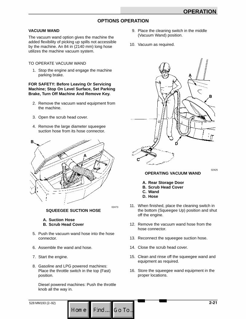
VACUUM WAND
The vacuum wand option gives the machine theadded flexibility of picking up spills not accessibleby the machine. An 84 in (2140 mm) long hoseutilizes the machine vacuum system.
TO OPERATE VACUUM WAND
1. Stop the engine and engage the machineparking brake.
FOR SAFETY: Before Leaving Or ServicingMachine; Stop On Level Surface, Set ParkingBrake, Turn Off Machine And Remove Key.
2. Remove the vacuum wand equipment fromthe machine.
3. Open the scrub head cover.
4. Remove the large diameter squeegeesuction hose from its hose connector.
!
02473
SQUEEGEE SUCTION HOSE
A. Suction HoseB. Scrub Head Cover
5. Push the vacuum wand hose into the hoseconnector.
6. Assemble the wand and hose.
7. Start the engine.
8. Gasoline and LPG powered machines:Place the throttle switch in the top (Fast)position.
Diesel powered machines: Push the throttleknob all the way in.
9. Place the cleaning switch in the middle(Vacuum Wand) position.
10. Vacuum as required.
!
�
�
02425
OPERATING VACUUM WAND
A. Rear Storage DoorB. Scrub Head CoverC. WandD. Hose
11. When finished, place the cleaning switch inthe bottom (Squeegee Up) position and shutoff the engine.
12. Remove the vacuum wand hose from thehose connector.
13. Reconnect the squeegee suction hose.
14. Close the scrub head cover.
15. Clean and rinse off the squeegee wand andequipment as required.
16. Store the squeegee wand equipment in theproper locations.

OPERATION
528 MM193 (2–92)����
TRANSPORTING MACHINE
PUSHING OR TOWING MACHINE
The machine may be pushed or towed from thefront or the rear, using the bumpers provided,over short distances up to 1 mph (2 km/h).
Place a dolly under the rear wheels to traveldistances greater than 1 mile (1 km) or speedsover 1 mph (2 km/h).
MACHINE JACKING
The machine may be jacked up for service at thedesignated locations. Use a jack of adequatecapacity and good working condition. Always stopthe machine on a flat, level surface and block thetires before jacking the machine up. The frontjacking location is in the middle of the flat bottomedge of the machine frame.
The rear jacking locations are next to the rearwheels. Open the access doors to allow the jackto contact the bottom of the bumper.
TO JACK UP MACHINE
1. Drain the solution and recovery tanks.
2. Stop the engine and engage the machineparking brake.
FOR SAFETY: Before Leaving Or ServicingMachine; Stop On Level Surface, Set ParkingBrake, Turn Off Machine And Remove Key.
3. Block the tires, which are not being jackedup, in order to secure the machine position.
FOR SAFETY: When Servicing Machine, BlockMachine Tires Before Jacking Machine Up.
4. Use a jack of adequate capacity to raise themachine. Jack up the machine only at thedesignated locations.
04758
FRONT JACKING LOCATION
5. Block machine up with jack stands or similardevices near the designated jackinglocations to secure the machine.
FOR SAFETY: When Servicing Machine, JackMachine Up At Designated Locations Only.Block Machine Up With Jack Stands. UseHoist Or Jack Of Adequate Capacity To LiftMachine.
6. Lower the machine onto the jack stands.
7. Check to make sure the machine is secure.
8. Service the machine as required.
9. When finished servicing the machine, raisethe machine off the jack stands.
10. Remove the jack stands from under themachine.
11. Lower the machine.
12. Remove the blocks from the tires.

OPERATION
����528 MM193 (1–89)
MACHINE TIE–DOWNS
The machine may be tied down at each of thefour corners of the machine at the locationsspecified.
To tie the front of the machine down, use thetie–down slots provided. The front tie–down slotsare located in the front corner of the machineframe.
!
04759
FRONT LEFT TIE–DOWN SLOT
A. Tie–Down SlotB. Machine Bumper
To tie the rear of the machine down, wrap chainsaround each corner of the rear bumper. Thensecure the other end of the chain to the trailer ortruck bed tie–downs.
When transporting the machine on a trailer or in atruck, be sure to engage the machine parkingbrake and block the machine tires to prevent themachine from rolling.

OPERATION
528 MM193 (6–94)���
MACHINE STORAGE
STORING MACHINE
When storing the machine for extended periods oftime, these procedures must be followed to lessenthe chance of rust, sludge, and other undesirabledeposits from forming:
1. Drain and clean the solution and recoverytanks.
2. Change engine oil.
3. Place the scrub head switch in the bottom(Scrub Head Up) position.
4. Park the machine in a cool and dry area.
5. Stop the engine and engage parking brake.
6. Block scrub head up.
7. Fill the hydraulic reservoir with hydraulic fluidto the full mark to prevent excessivecondensation from forming in the reservoir.
8A. Gasoline and LPG powered machines: Tostore the machine 30 to 90 days:
1. Remove the spark plugs.
2. Pour 3 oz (90 cc) of clean engine oilinto each spark plug hole.
3. Remove the ignition coil high tensionwire on machines below serial number031000. Operate the engine startermotor for at least a dozen revolutions.This distributes the oil over the cylinderwalls.
NOTE: Before preparing the engine for storage,allow it to cool down to the surroundingtemperature. Oil adheres to cold metal surfacesmuch better than hot surfaces.
4. Replace the high tension coil wire, onmachines below serial number 031000,and spark plugs.
5. Drain the gasoline from the carburetor.
6. LPG powered machines: Close theliquid service valve.
8B. Gasoline and LPG powered machines: Tostore the machine over 90 days:
1. Remove the spark plugs.
2. Pour 3 oz (90 cc) of clean engine oilinto each spark plug hole.
3. Remove the ignition coil high tensionwire on machines below serial number031000. Operate the engine startermotor for at least a dozen revolutions.This distributes the oil over the cylinderwalls.
NOTE: Before preparing the engine for storage,allow it to cool down to the surroundingtemperature. Oil adheres to cold metal surfacesmuch better than hot surfaces.
4. Replace the high tension coil wire, onmachines below serial number 031000,and spark plugs.
5. Drain the engine oil from the engine oilpan.
6. Drain the coolant from the radiator andengine block.
7. Close the engine cooling system draincocks.
8. Drain gasoline from the carburetor, fueltank, and the fuel lines.
9. Seal the air cleaner inlet and theexhaust outlet with weatherproofmasking tape.
10. Tighten the engine oil filler cap, the fueltank cap, and the radiator cap to makecertain they are securely in place.
11. LPG powered machines: Close theliquid service valve.
8C. Diesel powered machines: To storemachine:
1. Drain the coolant from the radiator andengine block.
2. Close the engine cooling system draincocks.

MAINTENANCE
���528 MM193 (3–95)
SECTION 3CONTENTS
PageRECOMMENDED FIRST 50–HOUR MACHINE
INSPECTION 3-3. . . . . . . . . . . . . . . . . . . . . . . MAINTENANCE CHART 3-4. . . . . . . . . . . . . . . . LUBRICATION 3-6. . . . . . . . . . . . . . . . . . . . . . . . .
ENGINE 3-6. . . . . . . . . . . . . . . . . . . . . . . . . . . GASOLINE AND LPG
POWERED ENGINES 3-6. . . . . . . . . . DIESEL POWERED ENGINES 3-6. . . . .
REAR SQUEEGEE ROLLER (For machines below serial number 033056) 3-6. . . . . . .
SCRUB HEAD PIVOTS 3-7. . . . . . . . . . . . . . FRONT CASTER AND
WHEEL BEARING 3-7. . . . . . . . . . . . . . . . STEERING ARM ROD ENDS 3-8. . . . . . . . . STEERING GEAR 3-8. . . . . . . . . . . . . . . . . . .
HYDRAULICS 3-9. . . . . . . . . . . . . . . . . . . . . . . . . HYDRAULIC FLUID 3-9. . . . . . . . . . . . . . . . . HYDRAULIC FLUID RESERVOIR 3-9. . . . .
TO DRAIN THE HYDRAULIC FLUID RESERVOIR 3-10. . . . . . . . . . . . . . . . . .
TO FILL THE HYDRAULIC FLUID RESERVOIR 3-10. . . . . . . . . . . . . . . . . .
HYDRAULIC FLUID RESERVOIR BREATHER 3-11. . . . . . . . . . . . . . . . . . . . . .
HYDRAULIC FLUID FILTER 3-11. . . . . . . . . . TO REPLACE HYDRAULIC FLUID
FILTER ELEMENT 3-11. . . . . . . . . . . . . HYDRAULIC PUMPS 3-12. . . . . . . . . . . . . . . .
TO START AND BREAK–IN HYDRAULIC PUMP 3-12. . . . . . . . . . . .
DIRECTIONAL PEDAL 3-12. . . . . . . . . . . . . . . TO ADJUST DIRECTIONAL CONTROL
PEDAL LINKAGE 3-13. . . . . . . . . . . HYDRAULIC FLUID LEAKS 3-13. . . . . . . . . . HYDRAULIC SYSTEM
TROUBLESHOOTING 3-14. . . . . . . . . . . . HYDRAULIC COMPONENTS
TROUBLESHOOTING 3-17. . . . . . . . . . . . HYDRAULIC SCHEMATIC (For machines
below serial number 030366) 3-18. . . . . . . HYDRAULIC SCHEMATIC, WITH SIDE
BRUSH OPTION (For machines below serial number 030366) 3-19. . . . . . .
HYDRAULIC SCHEMATIC (For machines serial number 030366 and above) 3-20. . .
HYDRAULIC SCHEMATIC, WITH SIDE BRUSH OPTION (For machines serial number 030366 and above) 3-21. . . . . . . .
PageENGINE 3-22. . . . . . . . . . . . . . . . . . . . . . . . . . . . . .
ENGINE LUBRICATION 3-22. . . . . . . . . . . . . . GASOLINE AND LPG POWERED
ENGINES 3-22. . . . . . . . . . . . . . . . . . . . DIESEL POWERED ENGINES 3-22. . . . .
COOLING SYSTEM 3-22. . . . . . . . . . . . . . . . . AIR INTAKE SYSTEM 3-23. . . . . . . . . . . . . . .
AIR FILTER RESTRICTION INDICATOR 3-23. . . . . . . . . . . . . . . . . . .
AIR FILTER 3-23. . . . . . . . . . . . . . . . . . . . . . TO REPLACE AIR
FILTER ELEMENT 3-24. . . . . . . . . . . . . FUEL SYSTEM – GASOLINE 3-25. . . . . . . . .
FUEL FILTER 3-25. . . . . . . . . . . . . . . . . . . . CARBURETOR 3-25. . . . . . . . . . . . . . . . . .
FUEL SYSTEM – LPG 3-26. . . . . . . . . . . . . . . LPG FUEL SYSTEM 3-26. . . . . . . . . . . . . . FUEL TANKS 3-27. . . . . . . . . . . . . . . . . . . . TO CHANGE AN LPG FUEL TANK 3-27. FUEL FILTER LOCK 3-28. . . . . . . . . . . . . . VAPORIZER–REGULATOR 3-28. . . . . . . . CARBURETOR 3-28. . . . . . . . . . . . . . . . . . OIL PRESSURE SWITCH 3-28. . . . . . . . . LPG FUEL TROUBLESHOOTING 3-29. .
FUEL SYSTEM – DIESEL 3-30. . . . . . . . . . . . DIESEL FUEL SYSTEM 3-30. . . . . . . . . . . FUEL WATER TRAP FILTER 3-30. . . . . . TO REPLACE FUEL
FILTER ELEMENT 3-30. . . . . . . . . . . . . PRIMING FUEL SYSTEM 3-30. . . . . . . . . TO PRIME FUEL SYSTEM 3-31. . . . . . . .
GOVERNOR – GASOLINE, LPG 3-31. . . . . . IGNITION SYSTEM – GASOLINE, LPG 3-31
SPARK PLUGS 3-31. . . . . . . . . . . . . . . . . . DISTRIBUTOR (For machines below
serial number 031000) 3-32. . . . . . . . . . ENGINE IGNITION TIMING (For machines
below serial number 031000) 3-32. . . . TO CHECK AND ADJUST IGNITION
TIMING (For machines below serial number 031000) 3-32. . . . . . . . . .
ENGINE IGNITION TIMING (For machinesserial number 031000 and above) 3-33
CYLINDER HEAD – GASOLINE, LPG 3-33. CYLINDER HEAD 3-33. . . . . . . . . . . . . . . . VALVE TAPPET CLEARANCE 3-34. . . . .
CYLINDER HEAD – DIESEL 3-34. . . . . . . . . . CYLINDER HEAD 3-34. . . . . . . . . . . . . . . . VALVE CLEARANCE 3-34. . . . . . . . . . . . .
CRANKCASE VENTILATION SYSTEM 3-34TUNE–UP CHART – GASOLINE, LPG 3-34.

MAINTENANCE
528 MM193 (10–89)���
PageELECTRICAL SYSTEM 3-35. . . . . . . . . . . . . . . . .
BATTERY 3-35. . . . . . . . . . . . . . . . . . . . . . . . . . . ELECTRICAL SCHEMATIC,
GASOLINE, LPG (For machines below serial number 031000) 3-36. . . . . . .
ELECTRICAL SCHEMATIC, GASOLINE, LPG (For machines serial number 031000 and above) 3-38. . .
ELECTRICAL SCHEMATIC, DIESEL 3-40. . BELTS AND CHAINS 3-42. . . . . . . . . . . . . . . . . . .
ENGINE FAN BELT 3-42. . . . . . . . . . . . . . . . . . STATIC DRAG CHAIN 3-42. . . . . . . . . . . . . . .
SCRUB HEAD 3-43. . . . . . . . . . . . . . . . . . . . . . . . . SCRUB HEAD 3-43. . . . . . . . . . . . . . . . . . . . . .
TO LEVEL SCRUB HEAD 3-43. . . . . . . . . BRUSHES 3-46. . . . . . . . . . . . . . . . . . . . . . . . . . . .
MAIN BRUSHES 3-46. . . . . . . . . . . . . . . . . . . . TO REPLACE MAIN BRUSHES 3-46. . . . TO CHECK AND ADJUST MAIN
BRUSH PATTERN 3-48. . . . . . . . . . . . . SIDE BRUSH 3-50. . . . . . . . . . . . . . . . . . . . . . .
TO REMOVE SIDE BRUSH 3-50. . . . . . . . TO INSTALL SIDE BRUSH 3-50. . . . . . . . TO ADJUST DOWN PRESSURE 3-51. . .
SQUEEGEES 3-52. . . . . . . . . . . . . . . . . . . . . . . . . SIDE SQUEEGEES 3-52. . . . . . . . . . . . . . . . .
TO REPLACE SIDE SQUEEGEE BLADES 3-52. . . . . . . . . .
TO ADJUST SIDE SQUEEGEES 3-52. . . SIDE SQUEEGEE LATCHES 3-53. . . . . . . . . REAR SQUEEGEE 3-53. . . . . . . . . . . . . . . . . .
TO REPLACE OR ROTATE REAR BLADE 3-53. . . . . . . . . . . . . . . . .
TO REPLACE FRONT BLADE 3-54. . . . . TO ADJUST REAR SQUEEGEE 3-55. . .
REAR SQUEEGEE RETAINING BAND CLAMPS 3-56. . . . . . . . . . . . . . . . . . . . . . . .
SIDE BRUSH SQUEEGEE 3-56. . . . . . . . . . . TO REPLACE SIDE BRUSH
SQUEEGEE 3-56. . . . . . . . . . . . . . . . . . SOLUTION AND RECOVERY TANKS 3-58. . . .
SOLUTION TANK 3-58. . . . . . . . . . . . . . . . . . . SOLUTION VALVE(S) 3-58. . . . . . . . . . . . . . . . SOLUTION SPREADER TUBE 3-58. . . . . . . RECOVERY TANK 3-59. . . . . . . . . . . . . . . . . . DEBRIS HOPPER 3-60. . . . . . . . . . . . . . . . . . . SRS� SOLUTION TANK 3-60. . . . . . . . . . . . . SRS� SOLUTION SPRAY NOZZLE 3-62. . .
BRAKES AND TIRES 3-63. . . . . . . . . . . . . . . . . . . SERVICE BRAKES 3-63. . . . . . . . . . . . . . . . . .
TO BLEED BRAKES 3-63. . . . . . . . . . . . . . PARKING BRAKES 3-63. . . . . . . . . . . . . . . . . . TIRES 3-63. . . . . . . . . . . . . . . . . . . . . . . . . . . . .

MAINTENANCE
���528 MM193 (6–94)
RECOMMENDED FIRST 50–HOUR MACHINE INSPECTION
After the first 50 hours of operation, the followingprocedures are recommended:
1. Perform the brush pattern test to check forcorrect brush adjustment.
2. Check the scrub head side squeegee bladesfor wear or damage.
3. Check the rear squeegee for worn ordamaged blades or for incorrect adjustment.
4. Check the vacuum hoses for damage orloose connections.
5. Gasoline and LPG powered machines belowserial number 031000: Check engine ignitiontiming.
6. Gasoline and LPG powered machines belowserial number 031000: Torque cylinder headbolts to the proper specification.
7. Replace the hydraulic fluid filter element.
8. Gasoline powered machines: Replace thefuel filter element.
9. Perform all remaining 50-hour lubricationand maintenance procedures listed in theMAINTENANCE CHART.

MAINTENANCE
528 MM193 (6–94)��
MAINTENANCE CHART
��
�
�
�
�
���
��������
��
�
��
��
�� �� �� ����
��
��
04752
No. ofService
Interval Key Description Procedure Lubricant Points
Daily 3 Engine crankcase Check oil level EO 19 Brushes Check for damage, wear and
adjustment – 210 Squeegees Check for damage, wear, and
adjustment – 419 Recovery tank Clean out – 117 Vacuum hoses Clean out – 320 Laminar tube set Flush – 114 SRS� tank screen filters Clean – 21 Radiator core exterior Check for debris and clean – 17 Engine air filter Check restriction indicator – 1
Empty dust cap – 122 Fuel water trap filter, Drain water – 1
diesel
50 Hours 3 Engine crankcase, diesel Change oil and filter element EO 118 Scrub head pivots Lubricate SPL 316 Rear squeegee roller Lubricate SPL 112 Steering arm rod ends Lubricate SPL 25 Front caster Lubricate SPL 16 Front wheel bearing Lubricate SPL 1
100 Hours 3 Engine crankcase, Change oil and filter element EO 1 gasoline, LPG
1 Radiator Check coolant level WG 121 Hydraulic fluid reservoir Check fluid level HYDO 12 Engine fan belt Check tension – 115 Parking brake Check adjustment – 1

MAINTENANCE
��528 MM193 (2–92)
No. ofService
Interval Key Description Procedure Lubricant Points
400 Hours 11 Brake master cylinder Check brake fluid level BF 14 Engine, gasoline, LPG, Check and adjust valve
for machines below clearances – 8 serial number 031000 Check and adjust idle speed – 1
Check and adjust idle mixture – 1Clean or replace and adjust spark plugs – 4Clean or replace and adjust distributor points – 1Clean and inspect distributor cap and rotor – 1Check and adjust ignition timing – 1Replace PCV valve – –Clean PCV hoses, tubes and fittings
4 Engine, gasoline, LPG, Check and adjust valve for machines serial clearances – 8 number 031000 and Check and adjust idle speed – 1 above Check and adjust idle mixture – 1
Clean or replace and adjust spark plugs – 4Replace PCV valve – –Clean PCV hoses, tubes and fittings
21 Hydraulic fluid reservoir Change hydraulic fluid HYDO 18 Hydraulic fluid filter Change filter element – 113 Steering gear Check grease level MPG 122 Fuel filter, diesel Replace element – 1
800 Hours 4 Engine Torque intake manifold bolts – 41 Cooling system Flush WG 121 Hydraulic reservoir
breather Replace – 121 Hydraulic reservoir
strainer Replace – 1
BF – Brake fluidEO – Engine oilHYDO – Tennant Company or approved hydraulic fluidMPG – Multi–purpose calcium soap base greaseSPL – Special lubricant, Lubriplate EMB grease (TENNANT Part No. 01433-1)WG – Water and permanent–type ethylene glycol anti–freeze, one–to–one ratio
NOTE: More frequent intervals may be required in extremely dusty conditions.

MAINTENANCE
528 MM193 (3–95)���
LUBRICATION
ENGINE
Check the engine oil level daily.
GASOLINE AND LPG POWERED ENGINES
Gasoline and LPG powered engines should belubricated with SAE–SG/SH rated engine oil.Change the engine oil and oil filter after every 100hours of operation.
The following oil grades are recommended forengines operating in the ambient temperatureslisted.
MULTI–VISCOSITY OILSBelow 32�F –10� to 90�F –10� to above 90�F Above 10�F
(Below 0�C) (–23� to 32�C) (–23 to above 32�C) (Above –12�C)5W 30 10W 30 10W 40 20W 40
SINGLE VISCOSITY OILS–10� to 32�F 10� to 60�F 32� to 90�F Above 60�F
(–23� to 0�C) (–12� to 16�C) (0� to 32�C) (Above 16�C)10W 20W 20 30 40
The engine oil capacity is 3.5 qt (3.3 L) includingthe oil filter.
DIESEL POWERED ENGINES
Diesel powered engines should be lubricated withSAE–CC/CD rated engine oil. Change the engineoil and oil filter after every 50 hours of operation.
The following oil grades are recommended forengines operating in the ambient temperatureslisted.
SINGLE AND MULTI–VISCOSITY OILSBelow 32�F 32� to 77� F Above 77� F(Below 0�C) (0� to 25� C) (Above 25� C)
10W 20 3010W 30
The engine oil capacity is 7 qt (6.7 L) including theoil filter.
REAR SQUEEGEE ROLLER (For machinesbelow serial number 033056)
The rear squeegee roller supports the rearsqueegee assembly. A grease fitting has beenprovided on the roller shaft for lubricationpurposes. Lubricate the roller bearing withLubriplate EMB grease (TENNANT Part No.01433–1) after every 50 hours of operation. Spinthe roller to distribute the grease.
!
00022
REAR SQUEEGEE ROLLER
A. CasterB. Caster Grease Fitting

MAINTENANCE
���528 MM193 (2–92)
SCRUB HEAD PIVOTS
The scrub head pivots when it is raised andlowered. Three grease fittings have been providedto lubricate the pivot points. Lubricate the pivotswith Lubriplate EMB grease (TENNANT Part No.01433–1) after every 50 hours of operation.
!
!00089
SCRUB HEAD PIVOT
A. Grease Fittings
FRONT CASTER AND WHEEL BEARING
The front caster wheel supports the weight of thefront of the machine. A grease fitting has beenprovided on the wheel to lubricate the wheelbearings and on the front of the caster for itslubrication. Lubricate the front wheel bearings andcaster with Lubriplate EMB grease (TENNANTPart No. 01433–1) after every 50 hours ofoperation.
�
!
�
�
02474
FRONT CASTER AND STEERING ARM
A. Front WheelB. Wheel Bearing Grease FittingC. Steering Arm Grease FittingD. Steering ArmE. Caster Grease Fitting
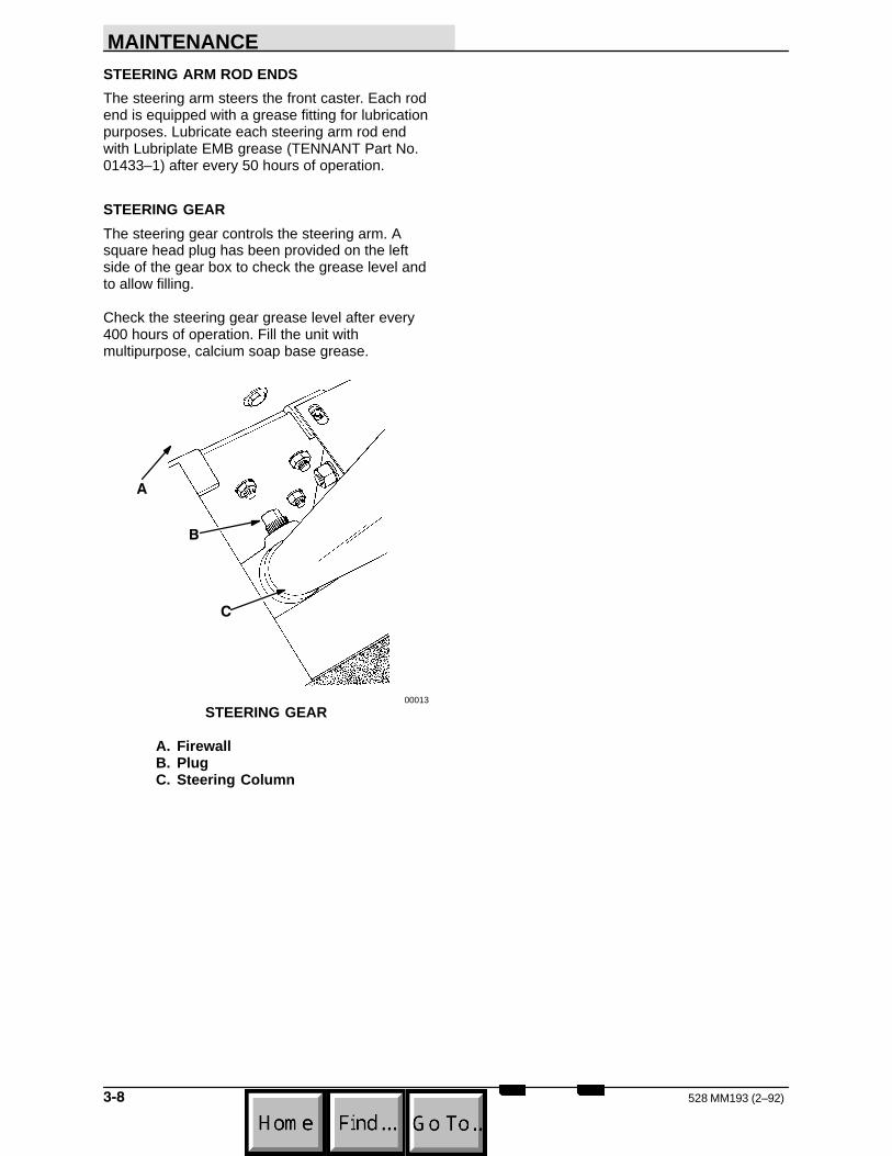
MAINTENANCE
528 MM193 (2–92)���
STEERING ARM ROD ENDS
The steering arm steers the front caster. Each rodend is equipped with a grease fitting for lubricationpurposes. Lubricate each steering arm rod endwith Lubriplate EMB grease (TENNANT Part No.01433–1) after every 50 hours of operation.
STEERING GEAR
The steering gear controls the steering arm. Asquare head plug has been provided on the leftside of the gear box to check the grease level andto allow filling.
Check the steering gear grease level after every400 hours of operation. Fill the unit withmultipurpose, calcium soap base grease.
!
�
00013
STEERING GEAR
A. FirewallB. PlugC. Steering Column

MAINTENANCE
���528 MM193 (2–92)
HYDRAULICS
HYDRAULIC FLUID
The quality and condition of the hydraulic fluidplays a very important role in how well themachine operates. TENNANT’s hydraulic fluid isdesigned to meet the special needs of itsmachines.
TENNANT’s hydraulic fluids provide longer life ofthe hydraulic components. There are two fluidsavailable for two different temperature ranges:
TENNANT part no. Ambient Temperatures65869 above 45� F (7� C)65870 below 45� F (7� C)
The higher temperature fluid is designed with ahigher viscosity and should not be used at thelower temperatures. Possible damage to thehydraulic pumps may occur because of improperlubrication.
The lower temperature fluid is a thinner fluiddesigned for colder temperatures.
If a locally-available hydraulic fluid is preferred, orif products of only one oil company are used,contact TENNANT Technical Customer Service tocheck the specifications of the substitute fluid.Using substitute fluids can cause prematurefailure of hydraulic components.
ATTENTION! Hydraulic components dependon system hydraulic fluid for internallubrication. If dirt or other contaminants areallowed to enter the hydraulic system,malfunctions, accelerated wear, and damagewill result.
HYDRAULIC FLUID RESERVOIR
Hydraulic fluid is stored in the hydraulic fluidreservoir. The reservoir holds 10 gal (38 L) ofhydraulic fluid. The reservoir is located under thebattery.
The reservoir is equipped with a breather–fillercap and fluid level dipstick mounted on thereservoir. See HYDRAULIC FLUID RESERVOIRBREATHER for breather service information.
!
04747
HYDRAULIC FLUID RESERVOIR
A. Hydraulic Reservoir
The hydraulic fluid level dipstick is built into thebreather–filler cap. The end of the dipstick ismarked with “full” and “add” levels. This indicatesthe level of hydraulic fluid in the reservoir.

MAINTENANCE
528 MM193 (6–94)����
Check the hydraulic fluid level after every 100hours of operation. It should be above the “add”marks on the dipstick, but not above the “full”mark when the hydraulic fluid is warm.
���������� ��
!
�
02430
HYDRAULIC FLUID LEVEL DIPSTICK
A. DipstickB. Full RangeC. Add Range
Do not overfill the hydraulic fluid reservoir.Hydraulic fluid expands as it heats to its normaloperating temperature. Always allow forexpansion when filling the reservoir.
ATTENTION! Do not overfill the hydraulic fluidreservoir or operate the machine with a lowlevel of hydraulic fluid in the reservoir.Damage to the machine hydraulic system mayresult.
Drain, flush, and refill the hydraulic fluid reservoirwith hydraulic fluid after every 400 hours ofoperation.
TO DRAIN THE HYDRAULIC FLUIDRESERVOIR
1. Stop the engine and engage the machineparking brake.
FOR SAFETY: Before Leaving Or ServicingMachine; Stop On Level Surface, Set ParkingBrake, Turn Off Machine And Remove Key.
2. Allow the hydraulic fluid to cool.
3. Open the side door.
4. Loosen the breather-filler cap. Remove thereservoir drain plug at the end of the drainhose located on the bottom of the reservoirto drain the hydraulic fluid. Discard the usedhydraulic fluid.
NOTE: Always change the hydraulic fluid filterwhen draining the hydraulic fluid reservoir.
5. Flush the reservoir with clean hydraulic fluidor suitable solvent. Do not use gasoline,kerosene, or diesel fuel.
6. Reinstall the reservoir drain plug.
7. Close the side door.
TO FILL THE HYDRAULIC FLUID RESERVOIR
1. Open the side door.
2. Remove the reservoir breather–filler cap.
3. Pour 10 gal (38 L) of new, approvedhydraulic fluid through a 200 mesh screenedfunnel and into the reservoir filler neck.
ATTENTION! Use only new, approvedhydraulic fluid to fill the hydraulic fluidreservoir.
4. Check the hydraulic fluid level in thereservoir with the reservoir dipstick.
5. Add hydraulic fluid until the level in thereservoir is between the “add” and the “full”range. Do not overfill.
NOTE: Do not overfill the hydraulic fluid reservoir.As hydraulic fluid heats to its normal operatingtemperature, it expands. Always allow for thisexpansion when filling the hydraulic fluid reservoir.
6. Lubricate the reservoir breather filler capwith a film of hydraulic fluid.
7. Place the reservoir breather–filler capsecurely on the reservoir.
8. Close the side door.
9. Start engine and operate all of the hydrauliccomponents. Then recheck the hydraulicfluid level.
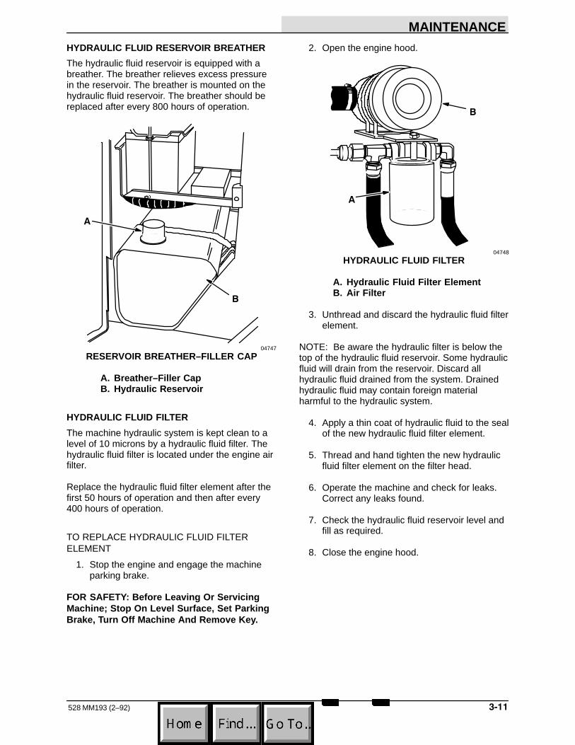
MAINTENANCE
����528 MM193 (2–92)
HYDRAULIC FLUID RESERVOIR BREATHER
The hydraulic fluid reservoir is equipped with abreather. The breather relieves excess pressurein the reservoir. The breather is mounted on thehydraulic fluid reservoir. The breather should bereplaced after every 800 hours of operation.
!
04747
RESERVOIR BREATHER–FILLER CAP
A. Breather–Filler CapB. Hydraulic Reservoir
HYDRAULIC FLUID FILTER
The machine hydraulic system is kept clean to alevel of 10 microns by a hydraulic fluid filter. Thehydraulic fluid filter is located under the engine airfilter.
Replace the hydraulic fluid filter element after thefirst 50 hours of operation and then after every400 hours of operation.
TO REPLACE HYDRAULIC FLUID FILTERELEMENT
1. Stop the engine and engage the machineparking brake.
FOR SAFETY: Before Leaving Or ServicingMachine; Stop On Level Surface, Set ParkingBrake, Turn Off Machine And Remove Key.
2. Open the engine hood.
!
04748
HYDRAULIC FLUID FILTER
A. Hydraulic Fluid Filter ElementB. Air Filter
3. Unthread and discard the hydraulic fluid filterelement.
NOTE: Be aware the hydraulic filter is below thetop of the hydraulic fluid reservoir. Some hydraulicfluid will drain from the reservoir. Discard allhydraulic fluid drained from the system. Drainedhydraulic fluid may contain foreign materialharmful to the hydraulic system.
4. Apply a thin coat of hydraulic fluid to the sealof the new hydraulic fluid filter element.
5. Thread and hand tighten the new hydraulicfluid filter element on the filter head.
6. Operate the machine and check for leaks.Correct any leaks found.
7. Check the hydraulic fluid reservoir level andfill as required.
8. Close the engine hood.

MAINTENANCE
528 MM193 (2–92)����
HYDRAULIC PUMPS
The machine propelling pump is a variabledisplacement hydraulic piston pump. It is drivenby the engine via a splined coupling.
The machine accessories pump is a hydraulicgear pump. It is tandem mounted to the hydraulicpiston pump.
After repairing or replacing a hydraulic pump, orwhen system contamination is likely, change thehydraulic fluid in the reservoir and the hydraulicfluid filter. Then the proper start and break–inprocedure must be followed to prevent possibledamage to the pump. TO START ANDBREAK–IN HYDRAULIC PUMP outlines theprocedure.
TO START AND BREAK–IN HYDRAULIC PUMP
1. Engage the machine parking brake andblock the front tire of the machine.
FOR SAFETY: Before Leaving Or ServicingMachine; Stop On Level Surface, Set ParkingBrake, Turn Off Machine And Remove Key.Block Machine Tires Before Jacking MachineUp.
2. Jack up the rear of the machine at thedesignated locations.
FOR SAFETY: When Servicing Machine, JackMachine Up At Designated Locations Only.Block Machine Up With Jack Stands.
3. Block up the machine with jack stands in thedesignated locations. Make sure the reartires clear the floor by 2 in (50 mm) and thefloor is cleared of all obstacles within a 24 in(610 mm) radius.
FOR SAFETY: When Servicing Machine, UseHoist Or Jack Of Adequate Capacity To LiftMachine.
4. Fill the hydraulic fluid reservoir with 10 gal (38 L) of new, approved hydraulic fluid.
5. Fill the hydraulic pump through the casedrain port with hydraulic fluid.
6. Remove the engine coil wire from the enginedistributor.
7. Operate the engine starter motor for three 10 second periods.
8. Replace the engine coil wire.
9. Start the engine and operate it at a low idlefor two minutes.
10. Press the directional control pedal one–halfof its travel in the “forward” direction whilealso operating the scrub brushes for oneminute.
11. Stop the engine.
12. Raise the rear of the machine, remove thejack stands, and lower the machine.
13. Fill the hydraulic fluid reservoir with new,approved hydraulic fluid.
14. Check the hose routings to be sure thehoses do not contact any moving, hot, orsharp surfaces.
15. Replace the hydraulic fluid filter after the firsthour of operation.
DIRECTIONAL PEDAL
The directional pedal controls the flow of hydraulicfluid to the hydraulic drive motors. The pedal hasthree positions – “forward,” “neutral,” and“reverse.” The “forward” and “reverse” positionssend hydraulic fluid to the drive motors to propelthe machine.
The “neutral” position is the position in which thepropelling pump sends no hydraulic fluid to thepropelling motors. The machine should not creepwhen the “neutral” position is correctly adjusted.Adjust the control pedal linkages whenever themachine creeps or after replacing the hydraulicpropelling pump or pump linkages.
FOR SAFETY: Before Leaving Or ServicingMachine; Stop On Level Surface, Set ParkingBrake, Turn Off Machine And Remove Key.

MAINTENANCE
����528 MM193 (2–92)
TO ADJUST DIRECTIONAL CONTROL PEDALLINKAGE
1. Stop the engine and engage the machineparking brake.
FOR SAFETY: Before Leaving Or ServicingMachine; Stop On Level Surface, Set ParkingBrake, Turn Off Machine And Remove Key.
2. Hold the directional control pedal in the“reverse” position. Adjust the pedal rodbetween the pedal and the bell crank sothere is 0.38 in (10 mm) between the bellcrank and the side of the machine frame.
!
�
�
�
02490
PUMP LINKAGE
A. Pedal RodB. Machine FrameC. Bell CrankD. Pump RodE. Pintle Arm
3. Adjust the pump rod and rod ball joints sothe machine travels 4 mph (6.4 km/h) in“reverse.” Make sure the adjustment alsogives a full stroke in the forward speed.
4. Adjust the pump pintle arm centering springsso the machine will not creep when thepedal is in the “neutral” position.
HYDRAULIC FLUID LEAKS
Fluid escaping from a very small hole can bealmost invisible. Use a piece of cardboard orwood, rather than hands, to search for suspectedleaks.
!
�
00002
HYDRAULIC PINHOLE LEAK
A. CardboardB. Pinhole LeakC. Magnifying Glass
If injured by escaping hydraulic fluid, see a doctorat once. Serious infection or reaction can developif proper medical treatment is not administeredimmediately.
FOR SAFETY: When Servicing Machine, UseCardboard To Locate Leaking Hydraulic FluidUnder Pressure.

MAINTENANCE
528 MM193 (7–89)���
HYDRAULIC SYSTEM TROUBLESHOOTING
SYMPTOM CAUSE REMEDY
Side brush won’t turn, or turns Bad coil at “SV4”. Replace coil.slowly. Everything else worksfine. Cartridge stuck open at “SV4”. Clean or replace cartridge.fine.
Bad seal at “SV4”. Replace seal.
Bad motor. Service or replace motor.
Bad rocker switch S7. Replace switch.
Bad rocker switch S8. Replace switch.
Bad relay M3. Replace relay.
Bad electrical connections. Remake connection.
Vacuum fan won’t turn, or Bad coil at “SV5”. Replace coil.turns too slowly. Everythingelse works fine. Cartridge stuck open at “SV5”. Clean or replace cartridge.else works fine.
Bad seal at “SV5”. Replace seal.
Bad motor. Service or replace motor.
Bad rocker switch S8. Replace switch.
Bad electrical connection at rockerswitch or solenoid valve.
Remake connection.
Side brush and vacuum fan Relief valve is stuck open. Clean or replace relief valve.won’t turn or turns slowly. Bad accessory pump. Service or replace pump.
Side brush won’t retract in Bad coil at “SV6”. Replace coil.reverse. Cartridge valve spool stuck Clean or replace cartridge.
closed at “SV6”.
Bad relay M3. Replace relay.
Bad electrical connection at relayor solenoid valve.
Remake connection.
Flow switch not working properly. Service or replace flow switch.
Side brush stays retracted. Cartridge valve spool stuck openat “SV6”.
Clean or replace cartridge.
Bad relay M3. Replace relay.
Flow switch stuck closed. Service or replace flow switch.
Side brush won’t go down. Bad coil at “SV7”. Replace coil.
Cartridge valve spool stuck closedat “SV7”.
Clean or replace cartridge.
Fixed pressure reducing valvestuck open.
Clean or replace cartridge.
Adjustable pressure reducingvalve stuck closed.
Clean or replace cartridge.
Bad rocker switch S–7 or S–8. Replace rocker switch.
Bad electrical connection at rockerswitch or solenoid valve.
Remake connection.
Side brush stays down, won’tcome up.
Cartridge valve spool is stuck inshifted position at “SV7”.
Clean or replace cartridge.
Bad rocker switch at S7. Replace switch.

MAINTENANCE
���528 MM193 (7–89)
SYMPTOM CAUSE REMEDY
Too much down force on sidebrush.
Pressure setting of adjustablepressure reducing valve is toohigh.
Turn adjustment knob counter–clockwise and lock in place withlock knob.
Fixed pressure reducing valvemalfunctioning, spool stuck in re-lieving mode.
Replace cartridge.
Adjustable pressure reducingvalve malfunctioning, spool stuckin spring held position.
Replace cartridge.
Not enough down force onside brush.
Pressure setting of adjustablepressure reducing valve is too low.
Turn adjustment knob clockwiseand lock in place with lock knob.
Fixed pressure reducing valvemalfunctioning.
Replace cartridge.
Adjustable pressure reducingvalve malfunctioning.
Replace cartridge.
Main brush motors won’t turn Bad coil at “SV1”. Replace coil.either direction. Cartridge stuck open at “SV1”. Clean or replace cartridge.
Relief valve stuck open. Clean or replace relief valve.
Bad seal on SV1. Replace seal.
Bad electrical connection at rockerswitch or solenoid valve.
Remake connection.
Bad rocker switch at S8 or S9. Replace switch.
Circuit breaker CB4 tripped. Reset circuit breaker CB4. Lookfor short circuit.
Bad accessory pump. Service or replace pump.
Main brush motors won’t turn *Bad coil at “SV9”. Replace coil.in clean mode. *Valve spool stuck at 4–way,
3–position valve.Manually shift valve with manualoverride to free binding spool.Clean or replace if necessary.
Bad rocker switch S9. Replace switch.
*Blown diode assembly at 45A/BRN wire.
Replace diode assembly.
Main brush motors won’t turn *Bad coil at “SV8”. Replace coil.in soak mode. *Valve spool stuck at 4–way,
3–position valve.Manually shift valve with manualoverrides to free binding spool,clean or replace if necessary.
Bad rocker switch S9. Replace switch.
*Blown diode assembly at 43A/GRN wire.
Replace diode assembly.
* Applies to machines below serial number 030366.

MAINTENANCE
528 MM193 (7–89)����
SYMPTOM CAUSE REMEDY
Squeegee won’t go up. Bad coil at “SV3”. Replace coil.
Cartridge valve spool stuck at“SV3”.
Clean or replace cartridge.
Bad electrical connection at SV3. Remake connection.
Bad relay M3. Replace relay M3.
Circuit breaker CB3 tripped. Reset circuit breaker CB–3. Lookfor short circuit.
Flow switch S6 not workingproperly.
Service or replace flow switch.
Scrub head won’t go down. Bad coil at “SV10”. Replace coil.
Cartridge valve spool stuck at“SV10”.
Clean or replace cartridge.
Cartridge valve spool stuck inshifted position at “SV2”.
Clean or replace cartridge.
Bad rocker switch S8. Replace switch.
Bad electrical connection at rockerswitch or solenoid valve SV10.
Remake Connection
Scrub head won’t go up. Bad coil at “SV2”. Replace coil.
Cartridge valve spool stuck at“SV2”.
Clean or replace cartridge.
Check valve stuck. Clean or replace check valve.
Relief valve stuck open. Clean or replace relief valve.
Bad rocker switch S–8. Replace switch.
Bad coil at SV1. Replace coil.
Cartridge valve spool stuck atSV1.
Clean or replace cartridge.
Blown diode assembly at 44/BLU. Replace diode assembly.
Bad electrical connection. Remake connection.
Scrub head lowers slowly withmachine turned off.
Pilot check valve seat damaged,allowing leakage.
Replace pilot check valve.
Main brush motors turn too Bad seal at “SV1”. Replace seal.slowly. Bad seal at “SV2”. Replace seal.
Bad seal at “SV10”. Replace seal.
Bad seal at “SV3”. Replace seal.
*Spool not shifting fully on 4–way,3 position directional valve.
Manually shift valve with manualoverrides to free binding spool.Clean or replace if necessary.
Relief valve stuck partially open. Clean or replace cartridge.
Cartridge at “SV1” stuck partiallyopen when shifted.
Clean or replace cartridge.
Pump flow is low. Service or replace gear pump.
Bad motors. Service or replace motors.
* Applies to machines below serial number 030366.

MAINTENANCE
����528 MM193 (7–89)
HYDRAULIC COMPONENTS TROUBLESHOOTING
Problem Cause Remedy
Hydraulic cylinder failure. Piston seals leaking. Replace cylinder.
Barrel worn or rod bent. Replace cylinder.
Hydraulic control valve failure. Valve seals leaking. Install seal kit.
Check valve sticking. Replace check valve.
Relief valve stuck open (leaking). Clean or replace relief valve.
Hydraulic solenoid valve Valve seals leaking. Install seal kit.failure. Solenoid coil failure. Replace solenoid coil or valve.
Solenoid spool sticking. Replace valve.
Flow sensing switch failure. Repair or replace flow sensingswitch.
Hydraulic motor failure. Motor leaking. Install seal kit.
Drive link failure. Replace drive link.
Gerotor worn. Replace gerotor set.
Output shaft failure. Replace output shaft andbearings.
Hydraulic gear pump failure. Pump leaking. Install seal kit.
Gear set failure. Replace gear set.
Relief valve stuck. Replace back plate assembly.
Engine–to–pump coupling failure. Replace coupling.
Hydraulic piston pump. Pump leaking. Install seal kit.
Relief valve stuck. Clean or replace relief valve.
Integral charge pump failure. Replace charge pump.
Rotating group worn. Replace rotating group.
Shaft failure. Replace shaft.
Backplate worn. Replace backplate.
Engine–to–pump coupling failure. Replace coupling.

MAINTENANCE
528 MM193 (6–94)����
04754
HYDRAULIC SCHEMATIC(For machines below serial number 030366)

MAINTENANCE
����528 MM193 (6–94)
04753
HYDRAULIC SCHEMATIC, WITH SIDE BRUSH OPTION(For machines below serial number 030366)

MAINTENANCE
528 MM193 (6–94)����
04754
HYDRAULIC SCHEMATIC(For machines serial number 030366 and above)
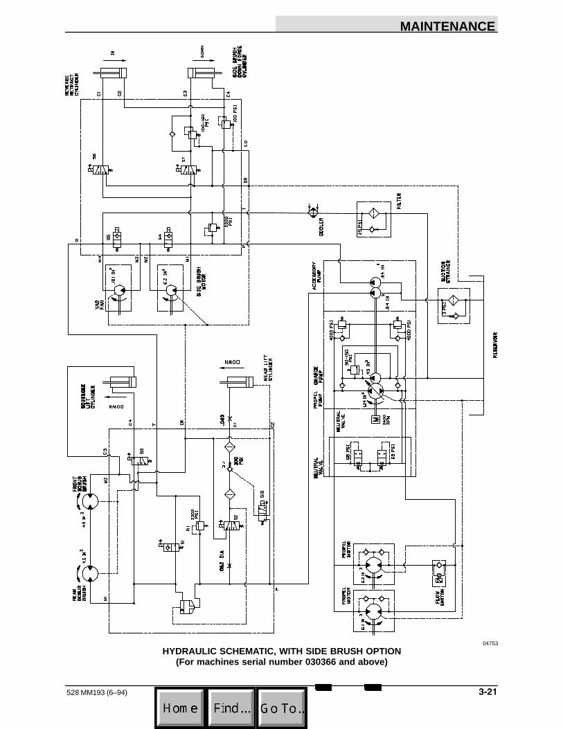
MAINTENANCE
����528 MM193 (6–94)
04753
HYDRAULIC SCHEMATIC, WITH SIDE BRUSH OPTION(For machines serial number 030366 and above)

MAINTENANCE
528 MM193 (6–94)����
ENGINE
ENGINE LUBRICATION
Check the engine oil level daily.
GASOLINE AND LPG POWERED ENGINES
Gasoline and LPG powered engines should belubricated with SAE–SG/SH rated engine oil.Change the engine oil and oil filter after every 100hours of operation.
The following oil grades are recommended forengines operating in the ambient temperatureslisted.
MULTI–VISCOSITY OILSBelow 32�F –10� to 90�F –10� to above 90�F Above 10�F
(Below 0�C) (–23� to 32�C) (–23 to above 32�C) (Above –12�C)5W 30 10W 30 10W 40 20W 40
SINGLE VISCOSITY OILS–10� to 32�F 10� to 60�F 32� to 90�F Above 60�F
(–23� to 0�C) (–12� to 16�C) (0� to 32�C) (Above 16�C)10W 20W 20 30 40
The engine oil capacity is 3.5 qt (3.3 L) includingthe oil filter.
DIESEL POWERED ENGINES
Diesel powered engines should be lubricated withSAE–CC/CD rated engine oil. Change the engineoil and oil filter after every 50 hours of operation.
The following oil grades are recommended forengines operating in the ambient temperatureslisted.
SINGLE AND MULTI–VISCOSITY OILSBelow 32�F 32� to 77� F Above 77� F(Below 0�C) (0� to 25� C) (Above 25� C)
10W 20 3010W 30
The engine oil capacity is 7 qt (6.7 L) including theoil filter.
COOLING SYSTEM
Maintaining cooling system efficiency is important.Engine temperatures must be brought up to andmaintained within the satisfactory range forefficient operation. However, the engine must bekept from overheating in order to prevent damageto the valves, pistons, and bearings. Check theradiator coolant level after every 100 hours ofoperation.
Use soft, clean water mixed with permanent–type,ethylene glycol antifreeze in a one–to–one ratio tofill the cooling system. Deposits of sludge, scale,and rust prevent normal heat transfer. Flush theradiator and the cooling system after every 800hours of operation, using a dependable cleaningcompound. Follow the mixing procedurerecommended by the compound manufacturer.This is important because of the difference inconcentration and composition of the cleaningcompounds. After cleaning, flush the system withclean water.
Whenever a cooling system is badly rust–clogged,as indicated by overflow loss or abnormally highoperating temperatures, corrective cleaning byreverse flow flushing will most effectively removethe heavy deposits of sludge, rust, and scale. Thereverse flow flushing should be performedimmediately after draining the cleaning solution.Flush the radiator first, then the engine, to allowthe engine to cool as much as possible.
Engine overheating may also be caused by dirtyradiator fins. The exterior fins of the radiator canbe cleaned with an air or water hose. Check theradiator core exterior daily for debris.
FOR SAFETY: When Servicing Machine, WearEye And Ear Protection When UsingPressurized Air Or Water.
Blow or rinse all dust, which may have collectedon the radiator, in through the grill and radiatorfins, opposite the direction of normal air flow. Thegrill and hydraulic cooler may be tilted back foreasier cleaning. Use care not to bend the coolingfins when cleaning. Clean thoroughly to preventcaking dust. Clean the radiator and cooler onlyafter the radiator has cooled to avoid cracking.
The engine is equipped with a 180� F (82� C)thermostat. Normal engine temperature is 200� F(93� C). Temperatures up to 220� F (104� C) areallowable. Temperatures over 220� F (104� C)indicate a problem exists.
NOTE: Overheating is always accompanied byloss of coolant water. If in doubt, check.

MAINTENANCE
����528 MM193 (3–95)
A pressure cap is used on the radiator to preventoverflow loss of water during normal operation.The spring–loaded valve in the cap closes theoutlet to the overflow pipe of the radiator and thusseals the system. Pressure developing within thesystem raises the boiling point of the coolant andallows higher temperatures without overflow lossfrom boiling. The pressure valve opens at 15 psi (100 kPa), allowing steam and water to pass outthe overflow pipe.
FOR SAFETY: When Servicing Machine, AvoidContact With Hot Engine Coolant. AllowEngine To Cool.
ATTENTION! Never pour cold water or coldantifreeze into the radiator of an overheatedengine. Allow the engine to cool and avoidthe danger of cracking the cylinder head orblock. Keep the engine running while addingwater.
AIR INTAKE SYSTEM
The importance of maintaining an air filter cannotbe overemphasized. Dirt ingested throughimproperly installed, improperly serviced, orinadequate air filter elements wears out moreengines than long hours of operation. Even asmall amount of dirt will wear out a set of pistonrings in just a few hours. Operating with a cloggedair filter element also causes the fuel mixture tobe richer, which can lead to formation of harmfulsludge deposits in the engine. Always cover theair intake when the air filter is removed forservicing. Do not neglect servicing the air filter.Use only correct parts for replacement. Keep allother air intake components such as hoses andclamps secure and in good condition to prevententrance of unfiltered air.
Overmaintenance can cause more damage thangood. Removing the air filter element more oftenthan is needed allows contaminants to enter theengine unnecessarily. Clean or replace the airfilter element only when the restriction indicatorindicates excessive restriction in the system.
AIR FILTER RESTRICTION INDICATOR
The air filter restriction indicator signals when toclean or replace the air filter element. Check therestriction indicator daily. The indicator’s red linewill move as the air filter element fills with dirt. Donot clean or replace the air filter element until thered line reaches 5 kPa and the “SERVICE WHENRED” window is filled with red. The serviceindicator red line may return to a lower reading onthe scale when the engine is shut off. The red linewill return to a correct reading when the engine isstarted.
Clean or replace the filter element when theservice indicator reads 5 kPa. After cleaning orservicing the air filter element, reset the serviceindicator by pushing the reset button on the end ofthe indicator.
!
�
02172
AIR FILTER RESTRICTION INDICATOR
A. Restriction IndicatorB. Indicator WindowC. Indicator Reset Button
AIR FILTER
The engine air filter housing includes a dust capand a dry cartridge–type air filter element. Thedust cap must be emptied of dirt daily. The airfilter element must be cleaned and inspected orreplaced whenever the yellow indicator of the airfilter restriction indicator reads 20 in (500 mm).The filter element must be replaced if it isdamaged or has been cleaned three times.

MAINTENANCE
528 MM193 (2–92)���
Service the air filter element only when therestriction indicator indicates excessive restrictionin the system. Do not remove the air filter elementunless it is restricting air flow.
TO REPLACE AIR FILTER ELEMENT
1. Stop the engine and engage the machineparking brake.
FOR SAFETY: Before Leaving Or ServicingMachine; Stop On Level Surface, Set ParkingBrake, Turn Off Machine And Remove Key.
2. Open the engine hood.
3. Unscrew the clamp ring on the filter.
4. Remove the dust cap.
5. Empty the dust cap by removing the rubberinsert.
!
02491
EMPTYING DUST CAP
A. Rubber InsertB. Dust Cap
6. Remove the filter wing nut.
7. Gently pull the filter element out of the filterhousing.
!
�
�
�
00044
REMOVING AIR FILTER ELEMENT
A. Filter HousingB. Clamp RingC. Filter ElementD. Wing NutE. Dust Cap
8. Clean the interior of the air cleaner housingwith a damp cloth. Clean the elementhousing sealing surfaces.
9. Using an air hose, direct dry, clean airmaximum 30 psi (205 kPa) up and downpleats on the inside of the filter. Do not rap,tap, or pound dust out of the element.
FOR SAFETY: When Servicing Machine, WearEye And Ear Protection When UsingPressurized Air Or Water.
!
00051
CLEANING AIR FILTER ELEMENT
A. Air HoseB. Filter Element

MAINTENANCE
���528 MM193 (6–94)
10. After cleaning the air filter element, inspect itfor damage by placing a bright light inside.The slightest rupture requires replacementof the filter. Clean and inspect the seals onthe ends of the element. They should beunbroken and flexible. Remember, theelement must be replaced after it has beencleaned three times.
!
03500
INSPECTING AIR FILTER ELEMENT
A. Bright LightB. Filter Element
11. Install the new or cleaned filter element sothat the fins on the element are at the intakeend of the air cleaner. Use care so that thefins are not damaged. Make sure theelement is seated evenly. Tighten theelement wing nut.
12. Install the dust cap with the arrows pointingup. Tighten the clamp ring to hold it in place.Check all intake hose connections for leaksor abrasion.
!
02492
DUST CAP
A. Dust Cap
13. Reset the air filter restriction indicator.
14. Close the engine hood.
FUEL SYSTEM – GASOLINE
FUEL FILTER
The fuel filters trap fuel impurities. One is locatedunder the fuel tank, the other is located on thecarburetor. Replace the filter elements after thefirst 50 hours of operation and then as required.
CARBURETOR
The carburetor has two basic adjustments. Thoseadjustments are idle fuel mixture and idle speed.Check and adjust idle fuel mixture and idle speedafter every 400 hours of operation. The idle fuelmixture is controlled by a screw located on thefront of the carburetor. Turning the screwclockwise, leans the fuel mixture. Turning thescrew counterclockwise, richens the fuel mixture.
FOR SAFETY: When Servicing Machine, AvoidMoving Parts. Do Not Wear Loose Jackets,Shirts, Or Sleeves When Working On Machine.
The idle speed is controlled by a screw located onthe side of the carburetor next to the throttlelinkage. Turning the screw clockwise increasesengine speed. Turning the screwcounterclockwise, decreases engine speed.Proper idle speed is 950 + 50 rpm with all optionsin the “off” position.
!
05509
CARBURETOR ADJUSTING SCREWS
A. Idle Fuel Mixture Adjusting ScrewB. Idle Speed Adjusting Screw
FOR SAFETY: When Servicing Machine, KeepFlames And Sparks Away From Fuel SystemService Area. Keep Area Well Ventilated.
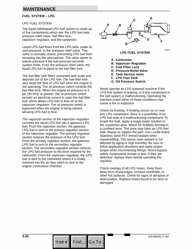
MAINTENANCE
528 MM193 (7–89)����
FUEL SYSTEM – LPG
LPG FUEL SYSTEM
The liquid withdrawal LPG fuel system is made upof five components which are: the LPG fuel tank,pressure relief valve, fuel filter lock,vaporizer–regulator, and the carburetor.
Liquid LPG fuel flows from the LPG tank, under itsown pressure, to the pressure relief valve. Thisvalve is normally closed, preventing LPG fuel fromescaping into the atmosphere. The valve opens torelieve pressure if the fuel pressure exceedssystem limits. From the pressure relief valve, theliquid LPG fuel is piped to the fuel filter lock.
The fuel filter lock filters unwanted tank scale anddeposits out of the LPG fuel. The fuel filter lockalso stops the flow of LPG fuel when the engine isnot operating. The oil pressure switch controls thefuel filter lock. When the engine oil pressure is 4psi (30 kPa) or greater, the oil pressure switchpermits an electrical current to open the fuel filterlock which allows LPG fuel to flow on to thevaporizer–regulator. The oil pressure switch isbypassed when the engine is being started,allowing LPG fuel to flow.
The vaporizer section of the vaporizer–regulatorconverts the liquid LPG fuel into a gaseous LPGfuel. From the vaporizer section, the gaseousLPG fuel is sent to the primary regulator sectionof the vaporizer–regulator. The primary regulatorsection reduces the pressure of the LPG fuel.From the primary regulator section, the gaseousLPG fuel is sent to the secondary regulatorsection. The secondary regulator section reducesthe LPG fuel pressure to the level required by thecarburetor. From the vaporizer–regulator, the LPGfuel is sent to the carburetor where it is finallymetered into the air flow which is sent to theengine combustion chamber.
!
��
"�
$
03511
LPG FUEL SYSTEM
A. CarburetorB. Vaporizer–RegulatorC. Fuel Filter LockD. Pressure Relief ValveE. Tank Service ValveF. LPG Fuel TankG. Oil Pressure Switch
Never operate an LPG powered machine if theLPG fuel system is leaking, or if any component inthe fuel system is malfunctioning. Operating themachine under either of these conditions maycause a fire or explosion.
Check for frosting. If frosting occurs on or nearany LPG component, there is a possibility of anLPG fuel leak or a malfunctioning component. Tolocate the leak, apply a soapy water solution tothe suspected area. Watch for bubbles forming ina confined area. This area may have an LPG fuelleak. Repair or replace the part. Use Loctite brandStainless Steel PST thread sealant whenreassembling. This epoxy–type sealant is notaffected by aging or high humidity. Be sure tofollow application directions and apply propertorque when reconnecting fittings. Never bypasssafety components except to test. If they aredefective, replace them before operating themachine.
Check routings of all LPG hoses. Keep themaway from sharp edges, exhaust manifolds, orother hot surfaces. Check for signs of abrasion ordeterioration. Replace hoses found to be worn ordamaged.

MAINTENANCE
����528 MM193 (2–92)
FUEL TANKS
The LPG fuel tanks should be inspected for sharpdents, gouges, leaks, and broken protecting ringswhenever the tanks are refilled. All tank valvesmust be inspected for leaks using a soap solution.Valves must also be checked for dirt, paint, orother debris in the valve openings. The followingspecific checks must also be made:
Filler Valve – Check for proper functioning and thepresence of the handwheel. Valve must be closedexcept during filling.
Vapor and Liquid Service Valves – Check forproper functioning and presence of thehandwheel. The valve must be closed exceptwhen in service.
Tank Service Valve Coupling – Check for properfunctioning, thread condition, and damaged ormissing washers or o–rings.
Safety Relief Valve – Check for damage. Checkfor the presence of the relief valve elbow and theproper direction of the elbow. If the rain cap ismissing, check for foreign matter and replace cap.Do not tamper with the relief valve setting.
Magnetic Liquid Level Gauge – Check operationagainst the maximum filling point as determinedby weight.
!
�
�
�
03485
TYPICAL LPG LIQUID WITHDRAWAL FUELTANK
A. Filler ValveB. Safety Relief ValveC. Liquid Service ValveD. Magnetic Liquid Level GaugeE. Tank Service Valve Coupling
An LPG fuel tank with any of the stated defectsmust be removed from service and be repaired ordestroyed accordingly.
If an LPG fuel tank is damaged or leaking, itshould be removed to a designated safe area,and the proper personnel should be notified. Donot attempt to make repairs to the tank,regardless of condition. Repairs or disposal mustonly be made by qualified personnel.
The care an LPG fuel tank receives has a directbearing on how long that tank can be used safely.LPG fuel tanks must not be dropped or draggedacross any surface. To move LPG fuel tanks, usea hand truck or roll the tank on its foot ring while itis being held in a position slightly off vertical.
Whether the storage is inside or outside, fueltanks should not be stored in the vicinity ofcombustible materials or high temperaturesources such as ovens and furnaces, since theheat may raise the pressure of the fuel to a pointwhere the safety relief valves would function.Care should be taken to insure that the tanks arestored in such a manner that if the safety reliefvalves do function, they will relieve vapor, ratherthan liquid.
Valves on empty tanks must be closed duringstorage and transportation.
Similar precautions should be taken in storingmachines fitted with LPG fuel tanks. They may bestored or serviced inside buildings, provided thereare no leaks in the fuel system and the tanks arenot overfilled. While machines are being repairedinside a building, the shut–off valve on the tankmust be closed, except when the engine must beoperated.
The tank changing operation presents anopportunity for the machine operator to carefullyobserve the tank, fittings, and fuel lines. Ifabnormal wear is detected, the operator shouldreport the findings to the appropriate personnel foraction.
TO CHANGE AN LPG FUEL TANK
1. Park the machine in a designated safe area.
FOR SAFETY: When Servicing Machine, KeepFlames And Sparks Away From Fuel SystemService Area. Keep Area Well Ventilated.
2. Close the tank service valve.

MAINTENANCE
528 MM193 (2–92)����
3. Operate the engine until it stops from lack offuel, then engage the machine parkingbrake.
FOR SAFETY: Before Leaving Or ServicingMachine; Stop On Level Surface, Set ParkingBrake, Turn Off Machine And Remove Key.
4. Put on gloves and remove thequick–disconnect tank coupling.
5. Inspect the LPG fuel lines for wear ordamage.
6. Disconnect the tank hold–down clamp andremove the empty LPG fuel tank from themachine.
7. Check the tank for damage or wear.
8. Store the tank in a designated safe area.
9. Select a filled LPG fuel tank and inspect itfor damage or leaks.
NOTE: Make sure the LPG fuel tank matches thefuel system (liquid tank with liquid system).
10. Carefully place the LPG tank in the machineso that the tank centering pin enters thealigning hole in the tank collar.
NOTE: If the pin cannot be engaged, make sureyou have the correct LPG fuel tank and thenadjust the pin locator in or out.
11. Fasten the tank hold–down clamp to lock thetank in position.
12. Connect the LPG fuel line to the tankservice coupling. Make sure the servicecoupling is clean and free of damage. Alsomake sure it matches the machine servicecoupling.
13. Open the tank service valve slowly andcheck for leaks. If an LPG leak is found,close the service valve immediately andnotify the appropriate personnel.
14. If no leaks are found, the engine is ready tostart.
FUEL FILTER LOCK
The fuel filter lock filters the LPG fuel. It alsostops the flow of LPG fuel to the engine when theengine is not operating or when the engine oilpressure is less than 4 psi (30 kPa).
Replace the filter pack with the filter packreplacement kit if diminished gas flow indicatesthe filter is clogged. A drain plug is provided forpurging the filter bowl. Clean out the bowl whenreplacing the filter pack.
VAPORIZER–REGULATOR
If any malfunction is noted, completelydisassemble the vaporizer–regulator. Clean all ofthe parts in alcohol. Inspect all of the parts andreplace where needed. Carefully reassemble thevaporizer–regulator with the seal repair kit. Checkfor proper operation.
CARBURETOR
If any malfunction is noted, completelydisassemble the carburetor. Clean all of the partsin alcohol.
Inspect all of the parts and replace when needed.Carefully reassemble the carburetor with the sealrepair kit.
FOR SAFETY: When Servicing Machine, KeepFlames And Sparks Away From Fuel SystemService Area. Keep Area Well Ventilated.
OIL PRESSURE SWITCH
The engine oil pressure switch requires no regularmaintenance. Never bypass the oil pressureswitch as this is a safety feature which preventsLPG fuel from flowing when the engine is notoperating properly.

MAINTENANCE
����528 MM193 (7–89)
LPG FUEL TROUBLESHOOTING
Problem Cause Remedy
Engine will not start Out of fuel Replace fuel tank with full one
Service valve opened too quickly -engaging safety valve
Close valve and reopen slowly
Plugged fuel filter Replace filter
Kinked or restricted fuel line Straighten or replace fuel line
Engine out of tune Tune-up engine
Oil pressure switch failure Replace oil pressure switch
Fuel lock valve failure Repair or replace fuel filter lock
Vaporizer-regulator failure Repair or replace vaporize -regulator
Engine runs unevenly or lackspower
Wrong type of fuel tank - vapor withdrawal tank
Replace vapor withdrawal tankwith liquid withdrawal tank
Plugged fuel filter Replace filter
Kinked or restricted fuel line Straighten or replace fuel line
Engine out of tune Tune-up engine
Restricted air filter Clean or replace air filter element
Vaporizer - regulator maladjusted Adjust vaporizer - regulator

MAINTENANCE
528 MM193 (2–92)����
",�%��*���(�0������%
DIESEL FUEL SYSTEM
The diesel fuel system is made up of five basiccomponents which are: fuel tank, fuel water trapfilter, fuel pump, injection pump, and injectors.
Fuel flows from the fuel tank through the fuelwater trap filter. The water trap filter separateswater and impurities from the fuel. From the fuelwater trap filter, fuel is drawn through the electricfuel pump and pumped to the injection pump.The injection pump pressurizes and sends fuel tothe injectors. The injectors atomize and injectproper amounts of fuel into the combustionchamber at the proper times. Excess fuel isreturned to the fuel tank through an overflow pipe.
FUEL WATER TRAP FILTER
The fuel water trap filter separates water andimpurities from the fuel. It is located next to theengine bellhousing. The bottom portion of the unitis the water trap. The middle portion is the filterelement.
Drain the water trap of water daily. To drain thewater trap, loosen the drain knob on the bottom ofthe unit. First water, then diesel fuel will drain.Tighten the drain knob when diesel fuel appears.
Replace the fuel filter element and clean the watertrap after every 400 hours of operation.
TO REPLACE FUEL FILTER ELEMENT
1. Stop the engine and engage the machineparking brake.
FOR SAFETY: Before Leaving Or ServicingMachine; Stop On Level Surface, Set ParkingBrake, Turn Off Machine And Remove Key.
2. Open the side and top engine access doors.
3. Loosen the vent plug and open the watertrap drain to drain diesel fuel.
FOR SAFETY: When Servicing Machine, KeepFlames And Sparks Away From Fuel SystemService Area. Keep Area Well Ventilated.
!
�
�
02765
FUEL WATER TRAP FILTER
A. Filter HeadB. Vent PlugC. Filter ElementD. Water Trap Bowl
4. Remove the filter element and the water trapfrom the filter head.
5. Remove the water trap bowl from the filterelement.
6. Clean the water trap bowl.
7. Lubricate the o–ring and spin the water trapbowl onto the new filter element.
8. Lubricate the o–ring and spin the filterelement and water trap onto the filter headand tighten the vent plug.
9. Bleed the fuel lines of air as described in TO PRIME FUEL SYSTEM.
10. Close the side and top engine access doors.
PRIMING FUEL SYSTEM
Priming the fuel system removes pockets of air inthe fuel lines and fuel components. Air in the fuelsystem will prevent smooth engine operation.
Prime the fuel system after running out of fuel,changing fuel filter elements or repairing a fuelsystem component.

MAINTENANCE
����528 MM193 (2–92)
TO PRIME FUEL SYSTEM
1. Stop the engine and engage the machineparking brake.
FOR SAFETY: Before Leaving Or ServicingMachine; Stop On Level Surface, Set ParkingBrake, Turn Off Machine And Remove Key.
2. Fill the fuel tank.
FOR SAFETY: When Servicing Machine, KeepFlames And Sparks Away From Fuel SystemService Area. Keep Area Well Ventilated.
3. Open the side and top engine access doors.
4. Open the air vent on top of the fuel injectionpump.
!
02766
FUEL INJECTION PUMP
A. Injection PumpB. Air Vent
5. Start the engine, operate it for one minute,then stop it; or operate the starter motor inten–second intervals until a steady stream offuel flows from the vent.
6. Close the air vent.
7. Close the access doors.
GOVERNOR – GASOLINE, LPG
The electronic governor controls engine speed. Itconsists of a control box located behind thebattery, and an actuator mounted on the engine.The control box regulates the actuator, which inturn controls the throttle.
The electronic governor is factory set and is notuser serviceable.
IGNITION SYSTEM – GASOLINE, LPG
SPARK PLUGS
Clean or replace and adjust spark plugs afterevery 400 hours of operation. Spark plug gaps arebest checked with a wire gauge unless the plug isdressed to obtain a correct reading with a flatgauge. The adjustment should always be madeon the side electrode and never on the centerelectrode, which may cause a broken porcelain.
“Gapping” the electrode tip is more easily donewith the proper tools.
!
�
�
01471
GAPPING SPARK PLUG
A. Spark PlugB. Gapping ToolC. Side ElectrodeD. Center Electrode
The proper spark plug gap is 0.035 in (0.9 mm)for machines below serial number 031000. Theproper spark plug gap is 0.039 in (1 mm) formachines serial number 031000 and above.

MAINTENANCE
528 MM193 (2–92)����
Spark plugs must be correctly installed in order toobtain good performance. It is a simple butimportant matter to follow these procedures wheninstalling plugs:
1. Clean the spark plug seat in the cylinderhead.
2. Use a new seat gasket and screw the plugin by hand.
3. Tighten the spark plugs to 22 to 28 ft lb (30 to 40 Nm) with a socket wrench of thecorrect size.
DISTRIBUTOR (For machines below serialnumber 031000)
The distributor operation is vital to the operation ofthe engine. The following items should becarefully inspected after every 400 hours ofnormal operation; however, dirt, dust, water, andhigh speed operation may cause more rapid wearand necessitate more frequent inspections:
1. Remove the distributor cap. Clean the capand examine for cracks, carbon runners, orcorroded terminals. If the vertical faces ofthe inserts are burned, install a new cap. Ifthe horizontal faces of the inserts areburned, replace the cap and the rotor as thiscondition is caused by the rotor being tooshort. Inspect cap to distributor seal and thedistributor housing breather.
2. Check the centrifugal advance mechanismfor “freeness” by turning the breaker cam inthe direction of rotation and then releasing it.The advance springs should return the camto its original position.
ENGINE IGNITION TIMING (For machines belowserial number 031000)
The engine ignition timing must be checked with atiming light, using the timing points located on thefront of the engine and the timing marks locatedon the crankshaft pulley. Distributor ignition timingshould be checked after the first 50 hours ofoperation and after every 400 hours of operationthereafter.
To check and adjust the ignition timing with ascope, refer to the scope manufacturer’sinstructions. To check and adjust the timing with atiming light, see TO CHECK AND ADJUSTIGNITION TIMING.
TO CHECK AND ADJUST IGNITION TIMING(For machines below serial number 031000)
NOTE: Dwell angle must be correct or timing willnot be accurate.
1. Stop the engine and engage the machineparking brake.
FOR SAFETY: Before Leaving Or ServicingMachine; Stop On Level Surface, Set ParkingBrake, Turn Off Machine And Remove Key.
2. Clean and mark the timing marks.
NOTE: Painting a white line on the front pulleytiming marks will make them more visible underthe timing light.
3. Disconnect and plug the vacuum hose fromthe distributor.
!
00696
ENGINE TIMING MARKS
A. Timing PointerB. Crankshaft Pulley
4. Connect the timing light to the No. 1 cylinderspark plug wire. Connect a tachometer tothe engine.
FOR SAFETY: When Servicing Machine, AvoidMoving Parts. Do Not Wear Loose Jackets,Shirts, Or Sleeves When Working On Machine.
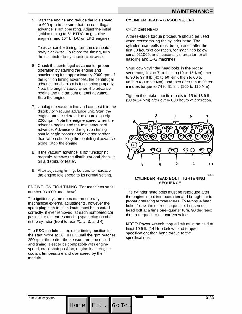
MAINTENANCE
����528 MM193 (2–92)
5. Start the engine and reduce the idle speedto 600 rpm to be sure that the centrifugaladvance is not operating. Adjust the initialignition timing to 6� BTDC on gasolineengines, and 10� BTDC on LPG engines.
To advance the timing, turn the distributorbody clockwise. To retard the timing, turnthe distributor body counterclockwise.
6. Check the centrifugal advance for properoperation by starting the engine andaccelerating it to approximately 2000 rpm. Ifthe ignition timing advances, the centrifugaladvance mechanism is functioning properly.Note the engine speed when the advancebegins and the amount of total advance.Stop the engine.
7. Unplug the vacuum line and connect it to thedistributor vacuum advance unit. Start theengine and accelerate it to approximately2000 rpm. Note the engine speed when theadvance begins and the total amount ofadvance. Advance of the ignition timingshould begin sooner and advance fartherthan when checking the centrifugal advancealone. Stop the engine.
8. If the vacuum advance is not functioningproperly, remove the distributor and check iton a distributor tester.
9. After adjusting timing, be sure to increasethe engine idle speed to its normal setting.
ENGINE IGNITION TIMING (For machines serialnumber 031000 and above)
The ignition system does not require anymechanical external adjustments, however thespark plug high tension leads must be insertedcorrectly, if ever removed, at each numbered coilposition to the corresponding spark plug numberin the cylinder (front to rear #1, 2, 3, and 4).
The ESC module controls the timing position inthe start mode at 10� BTDC until the rpm reaches250 rpm, thereafter the sensors are processedand timing is set to be compatible with enginespeed, crankshaft position, engine load, enginecoolant temperature and overspeed by themodule.
CYLINDER HEAD – GASOLINE, LPG
CYLINDER HEAD
A three-stage torque procedure should be usedwhen reassembling the cylinder head. Thecylinder head bolts must be tightened after thefirst 50 hours of operation, for machines belowserial 031000, and seasonally thereafter for allgasoline and LPG machines.
Snug down cylinder head bolts in the propersequence; first to 7 to 11 ft lb (10 to 15 Nm), thento 30 to 37 ft lb (40 to 50 Nm), then to 60 to 66 ft lb (80 to 90 Nm), and then after ten to fifteenminutes torque to 74 to 81 ft lb (100 to 110 Nm).
Tighten the intake manifold bolts to 15 to 18 ft lb (20 to 24 Nm) after every 800 hours of operation.
ÇÇ
Ç ÇÇ
ÇÇÇÇÇÇ
ÇÇ
ÇÇÇ
ÇÇÇÇ
�
�
�
�
�
�
�
��
03532
CYLINDER HEAD BOLT TIGHTENINGSEQUENCE
The cylinder head bolts must be retorqued afterthe engine is put into operation and brought up toproper operating temperatures. To retorque headbolts, follow the correct sequence. Loosen onehead bolt at a time one–quarter turn, 90 degrees;then retorque it to the correct value.
NOTE: Power wrench torque limit must be held atleast 10 ft lb (14 Nm) below hand torquespecification; then hand torque to thespecifications.

MAINTENANCE
528 MM193 (7–89)���
VALVE TAPPET CLEARANCE
The valve tappet clearance must be checked andadjusted if necessary after every 400 hours ofoperation.
To set the valve clearance without the engineoperating, rotate the crankshaft until No. 1cylinder is at the top of the compression stroke.Check the timing marks. It should read 0 or TDC.Both valves on No. 1 cylinder are now closed. Setthe valve clearance on both valves. Next, rotatethe crankshaft 180�, and set the valve lash onboth valves on No. 2 cylinder. Again rotate thecrankshaft 180�, and set the valve lash on bothvalves on No. 4 cylinder. Rotate the crankshaftanother 180�, and set the valve lash on bothvalves on No. 3 cylinder.
Check and adjust, for machines below serialnumber 031000, the intake valve clearance from0.009 in (0.22 mm), and the exhaust valveclearance from 0.023 in (0.59 mm) while theengine is cold.
Check and adjust, for machines serial number031000 and above, the intake valve clearancefrom 0.009 in (0.22 mm), and the exhaust valveclearance from 0.013 in (0.32 mm) while theengine is cold.
CYLINDER HEAD – DIESEL
CYLINDER HEAD
The cylinder head must be properly torqued afterservicing to ensure proper operation. Athree–stage torque procedure should be used.Snug down the cylinder head bolts and nuts in theproper sequence; first to one–third, thentwo–thirds, and then to the full torque specificationof 55 to 60 ft lb (75 to 80 Nm). Retighten thebolts and nuts after the first 30 minutes ofoperating the engine.
NOTE: Power wrench torque limit must be heldat least 10 ft lb (15 Nm) below torquespecification. Hand tighten to specification.
02767
CYLINDER HEAD BOLT TIGHTENING SEQUENCE
VALVE CLEARANCE
The valve clearance must be properly adjustedafter servicing or retorquing the cylinder headbolts to ensure proper operation. Measure valveclearance with a feeler gauge after aligning eachcylinder on the compression top dead centerstroke.
Adjust them with the engine cool to 0.0071 to0.0087 in (0.18 to 0.22 mm) in the firing order1–2–3.
CRANKCASE VENTILATION SYSTEM
Clean the crankcase ventilation hoses, tubes, andfittings and replace the PCV valve after every 400hours of operation.
TUNE–UP CHART – GASOLINE, LPG
Idle speed, no load 950 + 50 rpm
Maximum governedspeed, under load
2400 + 50 rpm
Spark plug gap (for machines belowserial number 031000)
0.035 in (0.9 mm)
Spark plug gap (for machines serialnumber 031000 andabove)
0.039 in (1 mm)
Timing (for machines below serial number
6� BTDC @ 600 rpm,gasoline
031000) 10� BTDC @ 600rpm, LPG
Firing order 1–2–4–3,counterclockwiserotation
Valve clearance, cold (for machines below
0.009 in (0.22 mm)intake
serial number031000)
0.023 in (0.59 mm)exhaust
Valve clearance, cold (for machines serial
0.009 in (0.22 mm)intake
number 031000 and above)
0.013 in (0.32 mm)exhaust

MAINTENANCE
���528 MM193 (2–92)
ELECTRICAL SYSTEM
BATTERY
The battery used in the machine is a lowmaintenance battery. It has been constructed withspecial materials and has extra electrolyte toreduce or eliminate maintenance. Its designreduces electrolyte loss and contamination. Donot add water, remove the battery vent plugs, orcheck the battery specific gravity.
The battery is rated at 12 V, 475 ccA. It is locatedunder the battery cover. When removing batterycables, remove the negative (–) cable before thepositive (+) cable.
Do not allow the battery to remain in dischargedcondition for any length of time.
Do not operate the machine if the battery is inpoor condition or with only 25% of the charge left.
Clean the top surface and the terminals of thebattery periodically. Use a strong solution ofbaking soda and water. Brush the solutionsparingly over the battery top, terminals, andcable clamps. Do not allow any baking sodasolution to enter the battery. Use a wire brush toclean the terminal posts and the cableconnectors. After cleaning, apply a coating ofclear petroleum jelly to the terminals and thecable connectors. Keep the top of the batteryclean and dry.
Keep all metallic objects off the top of the battery,as they may cause a short circuit. Replace wornor damaged wires.
The electrolyte level in regular non-sealedbatteries can be checked. It must always beabove the battery plates. Add distilled water tomaintain solution at the correct level above theplates, but do not overfill. Never add acid tobatteries, only distilled water. Keep vent plugsfirmly in place at all times, except when addingwater or taking hydrometer readings.
FOR SAFETY: When Servicing Machine, AvoidContact With Battery Acid.
If when checking battery specific gravity, one ormore battery cells tests lower than the otherbattery cells, (0.050 or more) the cell is damaged,shorted, or is about to fail.
NOTE: Do not take readings immediately afteradding water—if the water and acid are notthoroughly mixed, the readings may not beaccurate. Check the hydrometer readings againstthis chart:
SPECIFIC GRAVITY BATTERYat 80� F (27� C) CONDITION
1.260 – 1.280 100% charged1.230 – 1.250 75% charged1.200 – 1.220 50% charged1.170 – 1.190 25% charged1.110 – 1.160 Discharged
NOTE: If the readings are taken when the batteryelectrolyte is any temperature other than 80� F (26.6� C), the reading must be temperaturecorrected.
To determine the corrected specific gravityreading when the temperature of the batteryelectrolyte is other than 80� F (26.6� C):
Add to the specific gravity reading 0.004 (4 points)for each 10� F (5.5� C) above 80� F (26.6� C).
Subtract from the specific gravity reading 0.004 (4 points) for each 10� F (5.5� C) below 80� F (26.6� C).
!
04747
BATTERY
A. Battery

MAINTENANCE
528 MM193 (7–89)����
04756
ELECTRICAL SCHEMATIC, GASOLINE, LPG(For machines below serial number 031000)

MAINTENANCE
����528 MM193 (7–89)
04756
ELECTRICAL SCHEMATIC, GASOLINE, LPG(For machines below serial number 031000)

MAINTENANCE
528 MM193 (2–92)����
04756
ELECTRICAL SCHEMATIC, GASOLINE, LPG(For machines serial number 031000 and above)

MAINTENANCE
����528 MM193 (2–92)
04756
ELECTRICAL SCHEMATIC, GASOLINE, LPG(For machines serial number 031000 and above)

MAINTENANCE
528 MM193 (2–92)���
05173
ELECTRICAL SCHEMATIC, DIESEL

MAINTENANCE
���528 MM193 (2–92)
05173
ELECTRICAL SCHEMATIC, DIESEL

MAINTENANCE
528 MM193 (2–92)���
BELTS AND CHAINS
ENGINE FAN BELT
The engine fan belt is driven by the enginecrankshaft sheave and drives the engine fan andalternator. Check and adjust belt tension afterevery 100 hours of operation.
WARNING: Moving Fan Blades. KeepAway.
To adjust belt tension, loosen the alternatormounting bolts and pull the alternator away fromthe engine until the belt is snug; then tighten thebolts. Do not use a pry bar on the alternator as itwill damage the alternator. Proper belt tension isobtained when the belt deflects 0.5 in (13 mm)from a force of 8 to 10 lb (4 to 5 kg) applied atmidpoint of the longest span.
STATIC DRAG CHAIN
A static drag chain is provided to prevent thebuildup of static electricity in the machine. Thechain is attached on the rear of the machineframe and drags on the floor. Make sure that is ismaking contact with the floor at all times.
!
00033
STATIC DRAG CHAIN
A. Static Drag ChainB. Machine Frame

MAINTENANCE
���528 MM193 (2–92)
SCRUB HEAD
SCRUB HEAD
The scrub head houses the two scrub brushes,their drive mechanisms, and the side and rearsqueegee assemblies. The scrub head has oneadjustment—scrub head leveling. The scrub headleveling adjustment levels the scrub head. It isfactory set and should not be changed unless,due to a major parts replacement or machinedamage, the head adjustment may have beenaltered. If the scrub head is not level, the brusheswill bounce. There will also be excessive wear onthe brush drive plugs and bearings.
TO LEVEL SCRUB HEAD
1. Park the machine on a smooth level floor.
2. Lower the scrub head.
3. Stop the engine and engage the machineparking brake.
FOR SAFETY: Before Leaving Or ServicingMachine; Stop On Level Surface, Set ParkingBrake, Turn Off Machine And Remove Key.
NOTE: The scrub head must be adjusted withnew side and rear squeegees, and new scrubbrushes.
4. Center the rear squeegee tip adjusting blockbolts in their slots.
!
�
�
�
00011
ADJUSTING BLOCK BOLTS
A. Parallel ArmsB. SlotC. Tip Adjusting BlockD. Block BoltE. Squeegee
5. Check to make sure the rear squeegee linkpivots and lift pivot rotate freely.
6. Loosen the rear squeegee frame lift stud balljoint jam nuts.
7. Thread the two ball joints onto the stud asfar as possible.

MAINTENANCE
528 MM193 (2–92)��
8. The front blade of the rear squeegee shouldbe 0.25 + 0.06 in (6 + 2 mm) off the floorwhen the rear blade is resting on the flooruncurled.
9. Adjust the side squeegee adjusting bolts sothat the dimensions from the top of the boltto the top of the squeegee frame is 1.5 +0.06 in (38 + 2 mm).
!
00084
SQUEEGEE ADJUSTING BOLT
A. Adjusting BoltB. Side Squeegee Frame
10. Adjust the spray deflector upward until itcontacts the scrub head.
11. Loosen the four brush idler plate mountingbolts.
��
!
00049
BRUSH IDLER PLATE
A. Brush Idler PlateB. Mounting BoltsC. Adjusting Cams
12. Set both of the brush adjusting cams to thecenter position (rectangular portion of camhorizontal).
13. Tighten the four brush idler plate bolts.
14. Start the engine.
15. Raise and then lower the scrub head to thefloor so the rear squeegee rests on the floorbut is not curled.
16. Stop the engine.
FOR SAFETY: Before Leaving Or ServicingMachine; Stop On Level Surface, Set ParkingBrake, Turn Off Machine And Remove Key.
17. Adjust the rear squeegee caster down to thefloor with the caster adjustment screw. Makesure it is squarely positioned on the floor,then tighten the locking screws.
!
�
00022
REAR SQUEEGEE CASTER
A. Caster WheelB. Caster Adjustment ScrewC. Locking Screw
18. Start the engine, release the parking brake,and move the machine forward to deflect thesqueegee blades.
19. Stop the engine and engage the parkingbrake.
FOR SAFETY: Before Leaving Or ServicingMachine; Stop On Level Surface, Set ParkingBrake, Turn Off Machine And Remove Key.
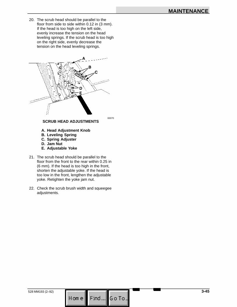
MAINTENANCE
��528 MM193 (2–92)
20. The scrub head should be parallel to thefloor from side to side within 0.12 in (3 mm).If the head is too high on the left side,evenly increase the tension on the headleveling springs. If the scrub head is too highon the right side, evenly decrease thetension on the head leveling springs.
�
�
!
�
00070
SCRUB HEAD ADJUSTMENTS
A. Head Adjustment KnobB. Leveling SpringC. Spring AdjusterD. Jam NutE. Adjustable Yoke
21. The scrub head should be parallel to thefloor from the front to the rear within 0.25 in (6 mm). If the head is too high in the front,shorten the adjustable yoke. If the head istoo low in the front, lengthen the adjustableyoke. Retighten the yoke jam nut.
22. Check the scrub brush width and squeegeeadjustments.

MAINTENANCE
528 MM193 (6–94)���
BRUSHES
MAIN BRUSHES
The main brushes are tubular and span the widthof the scrub head, sweeping debris into the debristrough while they scrub the floor. The brushesshould be inspected daily for damage or wear.Remove any string or wire found tangled on thescrub brushes, drive, or idler hubs.
The main brushes may be rotated front–to–rear toincrease brush life. Replace the main brusheswhen there is 0.5 in (13 mm) of brush bristle left.
The main brush patterns should be checked daily.They should be 2 to 3 in (50 to 75 mm) wide. Themain brush pattern is adjusted by turning theadjustment knob on top of the scrub head or theadjustment cams on the brush idler plate. See TOCHECK AND ADJUST MAIN BRUSH PATTERN.
TO REPLACE MAIN BRUSHES
1. Raise scrub head.
2. Stop engine and engage parking brake.
FOR SAFETY: Before Leaving Or ServicingMachine; Stop On Level Surface, Set ParkingBrake, Turn Off Machine And Remove Key.
3. Block scrub head up.
4. Raise and chain up the rear bumper.
WARNING: Heavy Bumper. Get Help ToHandle.
5. Open the lower left access door and the leftscrub head access door with a Allen wrench.The door fastener has a socket head.
�
!
00048
OPENING LEFT SCRUB HEAD ACCESS DOOR
A. Door FastenerB. Side Squeegee CoverC. Allen Wrench
6. Remove the four brush idler plate bolts.
!
�
�
��
00049
BRUSH IDLER PLATE
A. Rear BumperB. Left Side Access DoorC. BrushD. Brush Idler PlateE. Plate Bolts
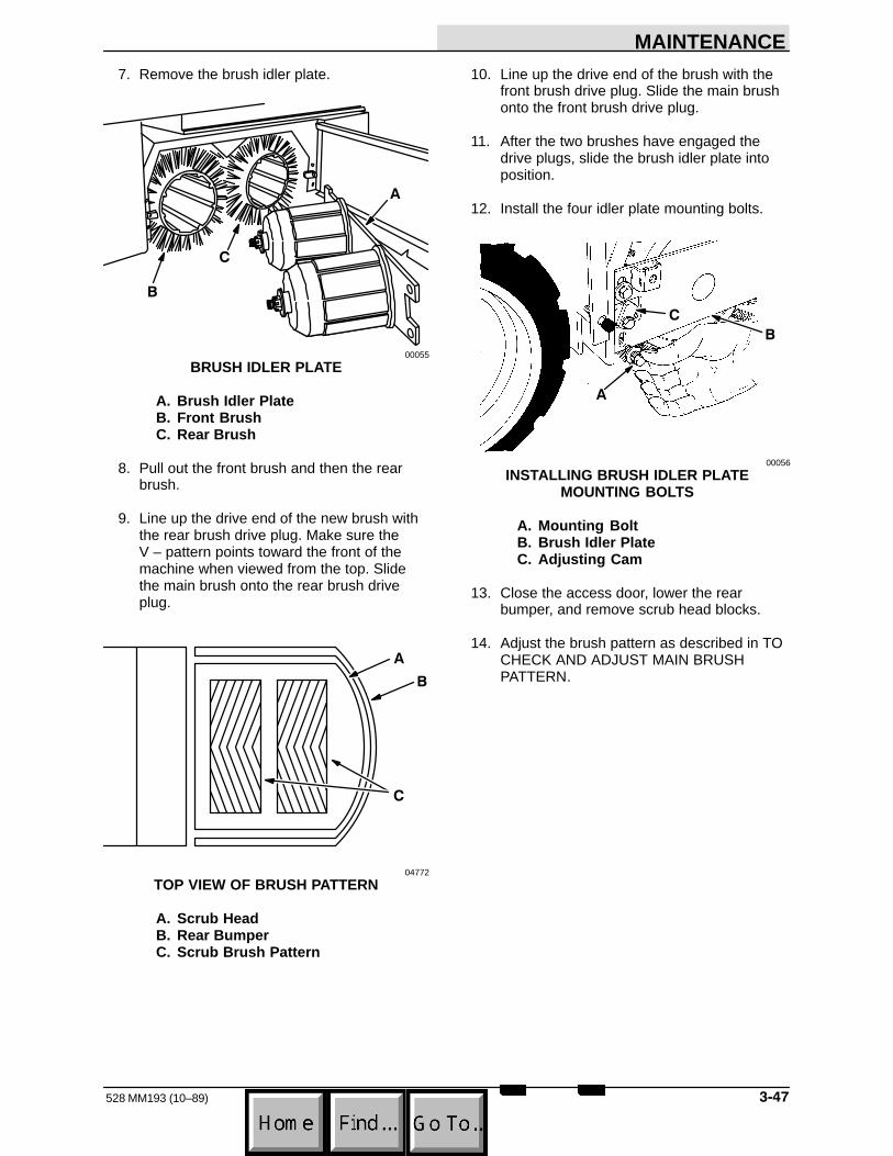
MAINTENANCE
���528 MM193 (10–89)
7. Remove the brush idler plate.
!
�
00055
BRUSH IDLER PLATE
A. Brush Idler PlateB. Front BrushC. Rear Brush
8. Pull out the front brush and then the rearbrush.
9. Line up the drive end of the new brush withthe rear brush drive plug. Make sure theV – pattern points toward the front of themachine when viewed from the top. Slidethe main brush onto the rear brush driveplug.
!
�
04772
TOP VIEW OF BRUSH PATTERN
A. Scrub HeadB. Rear BumperC. Scrub Brush Pattern
10. Line up the drive end of the brush with thefront brush drive plug. Slide the main brushonto the front brush drive plug.
11. After the two brushes have engaged thedrive plugs, slide the brush idler plate intoposition.
12. Install the four idler plate mounting bolts.
!
�
00056
INSTALLING BRUSH IDLER PLATEMOUNTING BOLTS
A. Mounting BoltB. Brush Idler PlateC. Adjusting Cam
13. Close the access door, lower the rearbumper, and remove scrub head blocks.
14. Adjust the brush pattern as described in TOCHECK AND ADJUST MAIN BRUSHPATTERN.
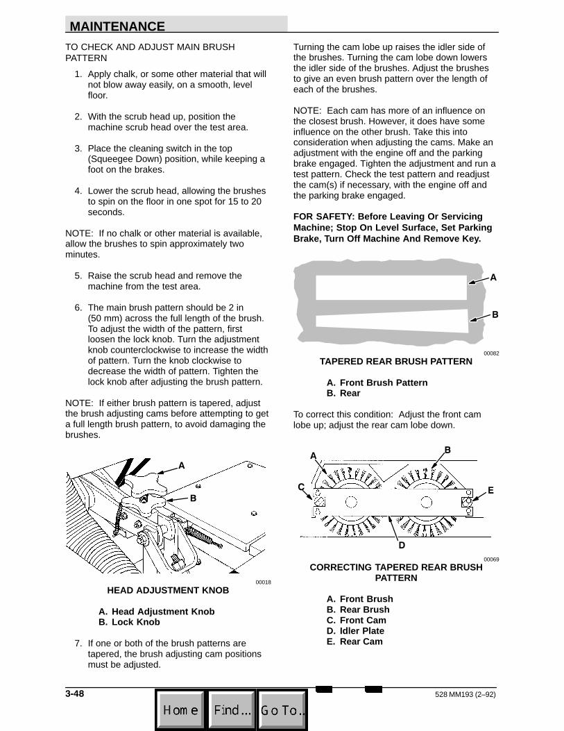
MAINTENANCE
528 MM193 (2–92)���
TO CHECK AND ADJUST MAIN BRUSHPATTERN
1. Apply chalk, or some other material that willnot blow away easily, on a smooth, levelfloor.
2. With the scrub head up, position themachine scrub head over the test area.
3. Place the cleaning switch in the top(Squeegee Down) position, while keeping afoot on the brakes.
4. Lower the scrub head, allowing the brushesto spin on the floor in one spot for 15 to 20seconds.
NOTE: If no chalk or other material is available,allow the brushes to spin approximately twominutes.
5. Raise the scrub head and remove themachine from the test area.
6. The main brush pattern should be 2 in (50 mm) across the full length of the brush.To adjust the width of the pattern, firstloosen the lock knob. Turn the adjustmentknob counterclockwise to increase the widthof pattern. Turn the knob clockwise todecrease the width of pattern. Tighten thelock knob after adjusting the brush pattern.
NOTE: If either brush pattern is tapered, adjustthe brush adjusting cams before attempting to geta full length brush pattern, to avoid damaging thebrushes.
!
00018
HEAD ADJUSTMENT KNOB
A. Head Adjustment KnobB. Lock Knob
7. If one or both of the brush patterns aretapered, the brush adjusting cam positionsmust be adjusted.
Turning the cam lobe up raises the idler side ofthe brushes. Turning the cam lobe down lowersthe idler side of the brushes. Adjust the brushesto give an even brush pattern over the length ofeach of the brushes.
NOTE: Each cam has more of an influence onthe closest brush. However, it does have someinfluence on the other brush. Take this intoconsideration when adjusting the cams. Make anadjustment with the engine off and the parkingbrake engaged. Tighten the adjustment and run atest pattern. Check the test pattern and readjustthe cam(s) if necessary, with the engine off andthe parking brake engaged.
FOR SAFETY: Before Leaving Or ServicingMachine; Stop On Level Surface, Set ParkingBrake, Turn Off Machine And Remove Key.
!
00082
TAPERED REAR BRUSH PATTERN
A. Front Brush PatternB. Rear
To correct this condition: Adjust the front camlobe up; adjust the rear cam lobe down.
�
!
�
�
00069
CORRECTING TAPERED REAR BRUSHPATTERN
A. Front BrushB. Rear BrushC. Front CamD. Idler PlateE. Rear Cam

MAINTENANCE
���528 MM193 (7–89)
!
00082
TAPERED FRONT BRUSH PATTERN
A. Front Brush PatternB. Rear Brush Pattern
To correct this condition: Adjust the front camlobe down; adjust the rear cam lobe up.
!
�
�
�
00069
CORRECTING TAPERED FRONT BRUSHPATTERN
A. Front BrushB. Rear BrushC. Front CamD. Idler PlateE. Rear Cam
!
00082
TAPERED BRUSH PATTERNS
A. Front Brush PatternB. Rear Brush Pattern
To correct this condition: Adjust both brush camlobes down.
!
�
�
�
00069
CORRECTING TAPERED BRUSH PATTERNS
A. Front BrushB. Rear BrushC. Front CamD. Idler PlateE. Rear Cam

MAINTENANCE
528 MM193 (2–92)���
!
00082
TAPERED BRUSH PATTERNS
A. Front Brush PatternB. Rear Brush Pattern
To correct this condition: Adjust both cam lobesup.
!
�
�
�
00068
CORRECTING TAPERED BRUSH PATTERNS
A. Front BrushB. Rear BrushC. Front CamD. Idler PlateE. Rear Cam
NOTE: If the front and rear brush patterns arenot equal in width, the head must be readjustedas described in To Level Scrub Head.
SIDE BRUSH
The side brush option scrubs debris from edgesinto the path of the main brushes. It should beinspected daily for wear or damage. Remove anystring or wire found tangled on the side brush orside brush drive hub.
The side brush should be replaced when theremaining brush bristle measures 0.5 in (15 mm)in length.
The down pressure of the side brush option isadjustable. The brush pressure can be adjusted toincrease cleaning performance of the side brush.
TO REMOVE SIDE BRUSH
1. Place the side brush switch in the bottom(Side Brush Up) position.
2. Stop engine and engage parking brake.
FOR SAFETY: Before Leaving Or ServicingMachine; Stop On Level Surface, Set ParkingBrake, Turn Off Machine And Remove Key.
3. Press the brush spring clip together with athumb and index finger, and apply downwardpressure to the scrub brush to release itfrom the brush drive hub.
TO INSTALL SIDE BRUSH
1. Slide the side brush under the drive hub.
2. Line up the hex socket of the scrub brushwith the hex on the drive hub.
3. Press the brush spring clip together and liftthe scrub brush into place over the brushdrive hub. Release the spring clip when thebrush is in place.
!
�
04755
SIDE BRUSH
A. Side BrushB. Spring ClipC. Drive Hub

MAINTENANCE
���528 MM193 (2–92)
TO ADJUST DOWN PRESSURE
1. Stop engine and engage parking brake.
FOR SAFETY: Before Leaving Or ServicingMachine; Stop On Level Surface, Set ParkingBrake, Turn Off Machine And Remove Key.
2. Open the engine hood.
3. Locate the hydraulic valve mounted on thefirewall.
4. To decrease the down pressure of the sidebrush, turn the adjustment knobcounter-clockwise on the hydraulic valve.Turn the adjustment knob clockwise toincrease the down pressure of the sidebrush.
!
04757
SIDE BRUSH DOWN PRESSUREADJUSTMENT
A. Hydraulic ValveB. Down Pressure Adjustment Knob
5. Close the engine hood.
6. Scrub with the side brush and readjust downpressure if necessary.

MAINTENANCE
528 MM193 (6–94)���
SQUEEGEES
SIDE SQUEEGEES
The side squeegees control water spray andchannel water into the path of the rear squeegee.Check the side squeegees for damage, wear, andadjustment daily. Replace the side squeegeeblades and back–up strips whenever they becomedamaged or lose their shape or resiliency.
TO REPLACE SIDE SQUEEGEE BLADES
1. Raise the scrub head.
2. Place the squeegee switch in the “up”position.
3. Stop the engine and engage the machineparking brake.
FOR SAFETY: Before Leaving Or ServicingMachine; Stop On Level Surface, Set ParkingBrake, Turn Off Machine And Remove Key.
4. Block scrub head up.
5. Open the side squeegee latch and removethe side squeegee band, bridge, back–upstrip, and blade.
6. Place the back-up strip over the pins of thesqueegee frame.
7. Place the new side squeegee blade on thepins over the back–up strip.
8. Position the blade bridge on the squeegeeframe pins. Be sure the tapered edge isfacing the front of the machine.
9. Clip the rear of the retaining band over therear of the squeegee and the blade bridge.
10. Latch the side squeegee latch.
NOTE: Make sure the band is snug to thesqueegee, the back-up strip, and the bladebridge—adjust if necessary.
11. Adjust the side squeegee as described inTO ADJUST SIDE SQUEEGEES.
TO ADJUST SIDE SQUEEGEES
1. Lower the scrub head and move themachine forward.
2. Stop the engine and engage the machineparking brake.
FOR SAFETY: Before Leaving Or ServicingMachine; Stop On Level Surface, Set ParkingBrake, Turn Off Machine And Remove Key.
3. Check the squeegee blade deflection. Itshould deflect 0.5 in (13 mm). Adjust thesqueegees as needed.
4. To adjust squeegee blade deflection, firstloosen the lock nut. To increase squeegeeblade deflection, thread the down pressureadjustment screw into the assembly.
To decrease squeegee blade deflection,unthread the down pressure adjustmentscrew from the assembly.
Tighten lock nut to set the adjustment.
!
�
00084
SIDE SQUEEGEE BLADE ADJUSTMENTSCREW
A. Adjustment ScrewB. Side Squeegee FrameC. Lock Nut
NOTE: A side squeegee benchmark adjustmentis as follows: Adjust the down pressureadjustment screw so that the distance from thetop of the screw to the top of the side squeegeeframe is 1.5 + 0.06 in (38 + 2 mm). The sidesqueegees can be adjusted as required after theinitial setting.

MAINTENANCE
���528 MM193 (6–94)
SIDE SQUEEGEE LATCHES
The side squeegee latches hold the sidesqueegee blade assembly in place. Adjust thelatches when the squeegee band does not holdthe squeegee blade assembly snug or if the latchwill not latch completely.
To tighten the side squeegee band, thread thelatch hook into the latch pivot.
To loosen the side squeegee band, unthread thelatch hook out of the latch pivot.
!
�
00065
SIDE SQUEEGEE LATCH
A. Squeegee BandB. Latch HookC. Latch Pivot
REAR SQUEEGEE
The rear squeegee assembly channels water intothe vacuum fan suction. The front squeegee bladechannels the water, and the rear blade wipes thefloor. Check the rear squeegee assembly fordamage, wear, and adjustment daily.
Replace the front blade of the rear squeegeewhenever the blade has become damaged orwhen the blade no longer contacts the floor.
Rotate or replace the rear blade of the rearsqueegee if its leading edge is worn half–waythrough the thickness of the blade.
Each rear blade has four wiping edges. To usethem all, start with one wiping edge. To use thenext wiping edge, rotate the squeegeeend-for-end. To use the next wiping edge, rotatethe top edges down, bottom edges up. To use thelast edge, rotate the squeegee end-for-end.Replace the back-up strips if they becomedamaged or if they lose their resiliency.
TO REPLACE OR ROTATE REAR BLADE
1. Lower the rear squeegee.
2. Raise the scrub head.
3. Stop the engine and engage the machineparking brake.
FOR SAFETY: Before Leaving Or ServicingMachine; Stop On Level Surface, Set ParkingBrake, Turn Off Machine And Remove Key.
4. Block scrub head up.
5. Open the rear band clamp and remove thetwo squeegee back–up strips and thesqueegee blade.
6. Replace or rotate the rear blade to allow anew edge of the blade to face the front ofthe machine.
7. Place the squeegee blade over the pins ofthe squeegee frame.
8. Place the squeegee back-up strips on thepins; inner strip using top holes, outer stripusing lower holes.
!
��
�
00020
INSTALLING REAR SQUEEGEE BLADE
A. Squeegee FrameB. Rear Squeegee BladeC. Inner Back–up StripD. Outer Back–up StripE. Retaining Band Clamp
9. Position the squeegee retaining band overthe outer back-up strip.

MAINTENANCE
528 MM193 (2–92)��
10. Latch the retaining band clamp.
NOTE: Make sure the band is snug to thesqueegee and the back-up strips-adjust ifnecessary.
11. Adjust the rear squeegee as described inTO ADJUST REAR SQUEEGEE.
TO REPLACE FRONT BLADE
1. Lower the rear squeegee.
2. Lower the scrub head so the rear squeegeeis just off the floor.
3. Stop the engine and engage the machineparking brake.
FOR SAFETY: Before Leaving Or ServicingMachine; Stop On Level Surface, Set ParkingBrake, Turn Off Machine And Remove Key.
4. Disconnect the rear squeegee and debrisscreen suction hoses from the scrub headframe vacuum connections.
5. Remove the debris hopper.
!
�
��
02424
REMOVING DEBRIS HOPPER
A. Scrub Head CoverB. Vacuum ConnectionC. Squeegee Suction HoseD. Debris HopperE. Debris Screen Suction Hose
6. Open the front band clamp and remove thefront squeegee band and blade.
!
�
00011
FRONT BAND CLAMP
A. Band ClampB. Front BladeC. Squeegee Frame
7. Place the new squeegee blade over the pinsof the squeegee frame.
8. Position the squeegee retaining band overthe squeegee on the pins of the squeegeeframe.
!
�
�
00017
INSTALLING FRONT SQUEEGEE BLADE
A. Retaining BandB. Front BladeC. Band ClampD. Squeegee Frame

MAINTENANCE
��528 MM193 (2–92)
9. Engage the retaining band clamp.
NOTE: Make sure the band is snug to thesqueegee––adjust if necessary.
10. Adjust the rear squeegee as described inTO ADJUST REAR SQUEEGEE.
TO ADJUST REAR SQUEEGEE
1. Lower the scrub head and the rearsqueegee.
2. Stop the engine and engage the machineparking brake.
FOR SAFETY: Before Leaving Or ServicingMachine; Stop On Level Surface, Set ParkingBrake, Turn Off Machine And Remove Key.
3. Loosen the four squeegee tip adjuster locknuts and the squeegee caster adjustmentscrews.
!
�
�
00011
REAR SQUEEGEE LINKAGE
A. Parallel ArmsB. Tip Adjusting ScrewC. Tip Adjuster Lock NutD. Squeegee Frame
4. Position the squeegee so the blade justtouches the floor from end to end. To dothis, adjust the squeegee tip adjustingscrews to raise or lower the squeegee tips;tightening the screws brings the tips down,loosening the screws brings the tips up.
5. Tighten the four squeegee tip adjustinglocknuts.
6. Slide a 0.50 in (13 mm) thick block under thesqueegee caster.
7. Position the squeegee so the rear blade justtouches the floor. Tighten the squeegeecaster locking screws.
!
�
00022
REAR SQUEEGEE CASTER
A. Caster WheelB. Caster Adjustment ScrewC. Locking Screw
8. Remove the block from under the squeegeecaster.
9. Start the engine and disengage the parkingbrake.
10. Move the machine forward with the rearsqueegee down, the brushes on, and thescrub head down.
11. Stop the engine with the scrub head down.
12. Engage the machine parking brake.
FOR SAFETY: Before Leaving Or ServicingMachine; Stop On Level Surface, Set ParkingBrake, Turn Off Machine And Remove Key.
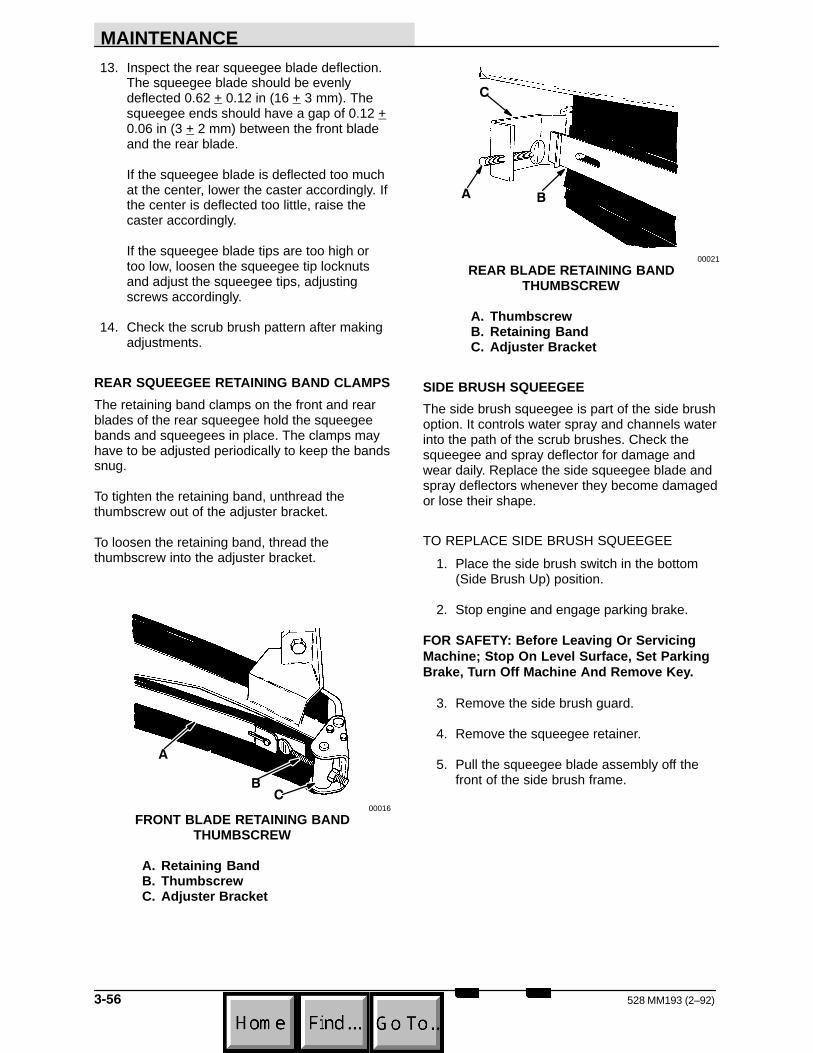
MAINTENANCE
528 MM193 (2–92)���
13. Inspect the rear squeegee blade deflection.The squeegee blade should be evenlydeflected 0.62 + 0.12 in (16 + 3 mm). Thesqueegee ends should have a gap of 0.12 +0.06 in (3 + 2 mm) between the front bladeand the rear blade.
If the squeegee blade is deflected too muchat the center, lower the caster accordingly. Ifthe center is deflected too little, raise thecaster accordingly.
If the squeegee blade tips are too high ortoo low, loosen the squeegee tip locknutsand adjust the squeegee tips, adjustingscrews accordingly.
14. Check the scrub brush pattern after makingadjustments.
REAR SQUEEGEE RETAINING BAND CLAMPS
The retaining band clamps on the front and rearblades of the rear squeegee hold the squeegeebands and squeegees in place. The clamps mayhave to be adjusted periodically to keep the bandssnug.
To tighten the retaining band, unthread thethumbscrew out of the adjuster bracket.
To loosen the retaining band, thread thethumbscrew into the adjuster bracket.
!
�
00016
FRONT BLADE RETAINING BANDTHUMBSCREW
A. Retaining BandB. ThumbscrewC. Adjuster Bracket
!
�
00021
REAR BLADE RETAINING BANDTHUMBSCREW
A. ThumbscrewB. Retaining BandC. Adjuster Bracket
SIDE BRUSH SQUEEGEE
The side brush squeegee is part of the side brushoption. It controls water spray and channels waterinto the path of the scrub brushes. Check thesqueegee and spray deflector for damage andwear daily. Replace the side squeegee blade andspray deflectors whenever they become damagedor lose their shape.
TO REPLACE SIDE BRUSH SQUEEGEE
1. Place the side brush switch in the bottom(Side Brush Up) position.
2. Stop engine and engage parking brake.
FOR SAFETY: Before Leaving Or ServicingMachine; Stop On Level Surface, Set ParkingBrake, Turn Off Machine And Remove Key.
3. Remove the side brush guard.
4. Remove the squeegee retainer.
5. Pull the squeegee blade assembly off thefront of the side brush frame.

MAINTENANCE
���528 MM193 (7–89)
6. Slide the new squeegee blade assemblyonto the side brush frame.
!
�
�
04755
SIDE BRUSH SQUEEGEE
A. Side Brush GuardB. Squeegee RetainerC. Squeegee Blade AssemblyD. Side Brush Frame
NOTE: Lubricating the side brush frame wherethe squeegee makes contact will make it easier toinstall the squeegee blade assembly.
7. Replace the squeegee retainer.
8. Remount the side brush guard.

MAINTENANCE
528 MM193 (7–89)���
SOLUTION AND RECOVERY TANKS
SOLUTION TANK
The machine solution tank supplies the scrubbrushes with a water and detergent solution. Thesolution tank on standard machines is located onthe right side of the machine under the operatorseat.
Access to the solution tank is through the openingin the top of the tank, under the operator seat.
The solution tank requires no regularmaintenance. If detergent cakes on the bottom ofthe tank, remove the deposits with a strong blastof water.
SOLUTION VALVE(S)
The solution valve(s) control the flow of solution tothe scrub brushes. The valve linkage should beadjusted to provide full flow and no flow to thescrub brushes.
SOLUTION SPREADER TUBE
The solution spreader tubes distribute scrubsolution to the scrub brushes. They may beflushed out if they become clogged with soap orother debris. A drain plug is located on each endof the spreader tube.
Before cleaning the solution spreader tube, makesure that the solution valve is opening fully whenthe scrub solution flow lever is moved all the wayforward.
A brush and hot water may be needed to removestubborn clogs. A sharp instrument may be usedto clear the small distribution holes in thespreader tube.
!
�
00033
SOLUTION SPREADER TUBE
A. Spreader TubeB. Tube PlugC. Distribution Holes

MAINTENANCE
���528 MM193 (2–92)
RECOVERY TANK
The machine recovery tank stores the watersolution picked up by the machine squeegee andvacuum fan. The recovery tank on standardmachines is located to the left of the operatorseat.
The recovery tank should be drained after thesolution tank is empty or whenever the ball floatrises and stops the water vacuum.
To drain the recovery tank, stop the engine,engage the parking brake, open the lower accessdoor, and unplug the drain hose next to a floordrain. The tank will not empty with the vacuum fanoperating. Shut off the vacuum fan by placing thecleaning switch in the bottom (Squeegee Up)position. Clean the recovery tank after every workshift.
�
!
�
00067
DRAINING RECOVERY TANK
A. Drain HoseB. Hose Retaining ClipC. Hose PlugD. Cleanout Door
Two doors have been provided to make the tankcleaning job easier. One door is located on top ofthe recovery tank. The other door is locatedbehind the lower left side access door.
Spray the inside of the tank with clean water.Remove all sludge and debris from the bottom ofthe tank, out the lower cleanout door.
FOR SAFETY: When Servicing Machine, WearEye And Ear Protection When UsingPressurized Air Or Water.
Spray the ball float. Make sure the float guidesare free of dirt and debris which may cause thefloat to stick.
!
�
02476
RECOVERY TANK BALLFLOAT
A. Vacuum Fan InletB. Ball Float GuideC. Ball Float
Keep vacuum hoses and nozzles clean. Cloggedhoses are a common cause of poor water pickup.

MAINTENANCE
528 MM193 (7–89)����
DEBRIS HOPPER
The debris hopper collects debris picked up bythe scrub brushes. It is located behind the scrubbrushes.
A vacuumized debris screen is located on thebottom of the debris hopper to draw water solutionout of the debris collected in the hopper.
The debris hopper should be emptied and cleanedwhenever the recovery tank is drained. To emptyand clean the debris hopper, stop the engine,engage the parking brake, open the scrub headcover, disconnect the vacuum hoses, and lift thehopper out of the machine. Remove and clean thedebris screen from the hopper. Reinstall thedebris screen, debris hopper, and vacuum hoseswhen finished.
!
�
�
� "
02424
REMOVING DEBRIS HOPPER
A. Scrub Head CoverB. Suction TubeC. Squeegee Suction HoseD. Debris HopperE. Debris ScreenF. Debris Screen Suction Hose
!
00027
REMOVING DEBRIS SCREEN
A. Debris Screen RetainerB. Debris Screen
SRS� SOLUTION TANK
The SRS� machine solution tank supplies thescrub brushes with a water and cleaning solutionmixture. It also stores water picked up by themachine squeegees and vacuum fan.
Access to the SRS� solution tank is through theopening in the top of the tank, under theoperator’s seat.

MAINTENANCE
����528 MM193 (2–92)
The SRS� solution tank should be drained andcleaned after every work shift. To drain the tank,stop the engine, engage the parking brake, openthe lower access doors, and unplug the drainhoses next to a floor drain. The tank will notempty with the vacuum fan operating. Shut off thevacuum fan by placing the cleaning switch in thebottom (Squeegee Up) position.
�
!
�
00067
DRAINING TANK
A. Drain HoseB. Hose Retaining ClipC. Hose PlugD. Cleanout Door
Four doors have been provided to make thecleaning job easier. One door is located under theseat; this is also the water fill door. The seconddoor is located on top of the tank next to themachine operator. The third door is locatedbehind the bottom left side access door. Thefourth door is located behind the bottom right sideaccess door.
FOR SAFETY: When Servicing Machine, WearEye And Ear Protection When UsingPressurized Air Or Water.
Spray the inside of the tank with clean water.Remove all sludge and debris from the bottom ofthe tank. Remove the laminar filter cover andspray the screen and filters clean.
NOTE: The laminar filter may be removed fromthe tank by removing the thumbscrew holding thefilter cover in place. Then lift the filter straight up.
!
00066
REMOVING LAMINAR FILTER COVERTHUMBSCREW
A. ThumbscrewB. Laminar Filter Cover
!
�
00031
REMOVING LAMINAR FILTER COVER
A. Laminar Filter CoverB. Laminar Filter TubesC. Screen

MAINTENANCE
528 MM193 (2–92)����
Spray the solution outlet screens with clean waterto remove all dirt and debris. Then fill the solutiontank with enough clean water to cover the solutionoutlet screens. Run the SRS� pump for a fewminutes to flush the system.
!
00001
SOLUTION OUTLET SCREENS
A. Outlet ScreensB. Lower Right Access Door Opening
FOR SAFETY: When Servicing Machine, WearEye And Ear Protection When UsingPressurized Air Or Water.
Spray the ball float clean. Make sure the floatguides are free of dirt and debris which maycause the float to stick. Check the vacuum hosesfor clogging or damage.
!
02476
RECOVERY TANK BALL FLOAT
A. Ball FloatB. Ball Float Guide
The SRS� solution tank has also been equippedwith a foam cross–over door. It has been providedin case a large amount of foaming regularlyoccurs, and flows out of the vacuum fan. With thefoam cross–over door removed, this foam willdissipate into the tank.
When operating the machine with the cross–overdoor removed, the solution tank must not be filledwith water above the two cross–over tubeslocated under the cross–over door.
!
00057
FOAM CROSS–OVER DOOR
A. Foam Cross–Over DoorB. Laminar Filter Cover
SRS� SOLUTION SPRAY NOZZLE
The SRS� solution spray nozzle distributes scrubsolution to the scrub brushes. It requires noregular maintenance. The spray nozzle should beadjusted so that the spray is centered across thefront brush.
!
00012
SOLUTION SPRAY NOZZLE
A. Solution Spray NozzleB. Machine Frame

MAINTENANCE
����528 MM193 (7–89)
BRAKES AND TIRES
SERVICE BRAKES
The service brakes are hydraulically activated bya master brake cylinder. Check the master brakecylinder fluid level after every 400 hours ofoperation and add brake fluid as needed. Themaster brake cylinder is located in front of theoperator in the engine compartment.
If necessary, adjust the brake clevis on the mastercylinder push rod so that the brake pedal is in ahorizontal position when the cylinder push rodstarts to engage the master cylinder piston.
!
04749
MASTER CYLINDER
A. Master Cylinder
Brakes require bleeding whenever air enters thesystem. Air can enter when the master cylinder orwheel cylinders are serviced or if the fluid in thereservoir runs dry. Air can also enter through aleaky brake line or hose. Find the leaking line andreplace it before bleeding the system.
Whenever handling brake fluid, do not get any onthe brake shoes, drums, or body paint. Brakepads will be permanently damaged, requiringreplacement. Body paint can also be damagedunless the area is wiped with a clean cloth andwashed with a soapy solution immediately.
TO BLEED BRAKES
1. Make sure that the brake fluid reservoir isfull and that the vent in the cap is open.
2. Connect a plastic or rubber tube to thebleeder valve on the left rear wheel.Suspend the other end of the tube in a jar orbottle filled with a few inches of brake fluid.During the remaining steps, keep this endsubmerged at all times and never let thelevel in the brake fluid reservoir drop belowone half full. This is to keep air from beingdrawn into the system.
3. Open the bleeder valve on the left rearwheel about one turn. Have an assistantpress the brake pedal slowly to the floor. Assoon as the pedal is all the way down, closethe bleeder valve and let the pedal up.Repeat this step as many times asnecessary, until fluid free of air bubblesflows from the tube.
4. Bleed the right rear wheel in the samemanner as described in the steps above.Keep checking the brake fluid reservoir to besure it doesn’t run out of fluid.
5. When all wheels are bled, discard the brakefluid in the jar or bottle; never reuse suchfluid.
6. Fill the brake fluid reservoir with clean fluid.
7. Check the brakes for proper operation.
PARKING BRAKES
The parking brakes are mechanically activated bythe parking brake lever and two cables.
The parking brakes should be adjusted wheneverit becomes very easy to engage the parkingbrake, when the machine rolls after engaging theparking brake, and after every 100 hours ofoperation. The parking brake may be tightened byturning the knurled knob on the end of the parkingbrake clockwise.
TIRES
The machine tires are solid. Periodically, wash offthe tires to remove built–up detergent and floorgrime.

MAINTENANCE
528 MM193 (7–89)���

APPENDIX
��528 MM193 (2–92)
SECTION 4CONTENTS
PageHARDWARE INFORMATION 4-3. . . . . . . . . . . .
STANDARD BOLT TORQUE CHART 4-3. . METRIC BOLT TORQUE CHART 4-3. . . . . BOLT IDENTIFICATION 4-3. . . . . . . . . . . . . . THREAD SEALANT AND LOCKING
COMPOUNDS 4-3. . . . . . . . . . . . . . . . . . . HYDRAULIC FITTING INFORMATION 4-4. . . .
HYDRAULIC TAPERED PIPE FITTING (NPT) TORQUE CHART 4-4. . . . . . . . . .
HYDRAULIC TAPERED SEAT FITTING (JIC) TORQUE CHART 4-4. . . . . . . . . . .
HYDRAULIC O-RING FITTING TORQUE CHART 4-4. . . . . . . . . . . . . . . . . . . . . . . . .

APPENDIX
528 MM193 (2–92)��

APPENDIX
��528 MM193 (2–92)
HARDWARE INFORMATION
The following charts state standard platedhardware tightening ranges for normal assemblyapplications. Decrease the specified torque by20% when using a thread lubricant. Do notsubstitute lower grade hardware for higher gradehardware. If higher grade hardware than specifiedis substituted, tighten only to the specifiedhardware torque value to avoid damaging thethreads of the part being threaded into, as whenthreading into speed nuts or weldments.
STANDARD BOLT TORQUE CHART
Thread SAE Grade 5 SAE Grade 8Size Torque ft lb (Nm) Torque ft lb (Nm)
0.25 in 7–10 (9–14) 10–13 (14–38)0.31 in 15–20 (20–27) 20–26 (27–35)0.38 in 27–35 (37–47) 36–47 (49–64)0.44 in 43–56 (58–76) 53–76 (72–103)0.50 in 65–85 (88–115) 89–116 (121–157)0.62 in 130–170 (176–231) 117–265 (159–359)0.75 in 215–280 (291–380) 313–407 (424–552)1.00 in 500–650 (678–881) 757–984 (1026–1334)
NOTE: Decrease torque by 20% when using athread lubricant.
METRIC BOLT TORQUE CHART
Thread Class 8.8 Class 10.9Size Torque ft lb (Nm) Torque ft lb (Nm)
M4 2 (3) 3 (4)M5 4 (5) 6 (8)M6 7 (9) 10 (14)M8 18 (24) 25 (34)M10 32 (43) 47 (64)M12 58 (79) 83 (112)M14 94 (127) 133 (180)M16 144 (195) 196 (265)M20 260 (352) 336 (455)M24 470 (637) 664 (900)
NOTE: Decrease torque by 20% when using athread lubricant.
Exceptions to the above chart:
Rear wheel hub nut – 175 ft lb (240 Nm)
BOLT IDENTIFICATION
Identification SpecificationGrade Marking and Grade
SAE–Grade 5
SAE–Grade 8
ISO–Grade 8.8
ISO–Grade 10.9
01395
THREAD SEALANT AND LOCKINGCOMPOUNDS
Thread sealants and locking compounds may beused on this machine. They include the following:
Locktite 515 sealant – gasket formingmaterial. TENNANT Part No. 75567,15 oz(440 ml) cartridge.
Locktite 242 blue – medium strength threadlocking compound. TENNANT Part No.32676, 0.5 ml tube.
Locktite 271 red – high strength threadlocking compound. TENNANT Part No.19857, 0.5 ml tube.

APPENDIX
528 MM193 (2–92)�
HYDRAULIC FITTING INFORMATION
HYDRAULIC TAPERED PIPE FITTING (NPT)TORQUE CHART
NOTE: Ratings listed are when using teflonthread seal.
Minimum MaximumSize Torque Torque
1/4 NPT 10 ft lb (14 Nm) 30 ft lb (41 Nm)1/2 NPT 25 ft lb (34 Nm) 50 ft lb (68 Nm)3/4 NPT 50 ft lb (68 Nm) 100 ft lb (136 Nm)
HYDRAULIC TAPERED SEAT FITTING (JIC)TORQUE CHART
Tube Thread MaximumO.D. (in) Size Torque
0.25 0.44–20 9 ft lb (12 Nm)0.38 0.56–18 20 ft lb (27 Nm)0.50 0.75–16 30 ft lb (41 Nm)0.62 0.88–14 40 ft lb (54 Nm)0.75 1.12–12 70 ft lb (95 Nm)1.0 1.31–12 90 ft lb (122 Nm)
HYDRAULIC O–RING FITTING TORQUECHART
Tube Thread Minimum MaximumO.D.(in) Size Torque Torque
0.25 0.44–20 6 ft lb (8 Nm) 9 ft lb (12 Nm)0.38 0.56–18 13 ft lb (18 Nm) 20 ft lb (27 Nm)
*10 ft lb (14 Nm) 12 ft lb (16 Nm)0.50 0.75–16 20 ft lb (27 Nm) 30 ft lb (41 Nm)
*21 ft lb (28 Nm) 24 ft lb (33 Nm)0.62 0.88–14 25 ft lb (34 Nm) 40 ft lb (54 Nm)0.75 1.12–12 45 ft lb (61 Nm) 70 ft lb (95 Nm)1.0 1.31–12 60 ft lb (81 Nm) 90 ft lb (122 Nm)
NOTE: Do not use sealant on o–ring threads.
*Aluminum bodied components