53 asee 2015 il-in section final draft
TRANSCRIPT

An Educational Platform for Electric Machines and Drives Simulation for Power and Energy Systems Programs
Constantin Apostoaia1 and Donald L. Gray2
1 Purdue University Calumet, Hammond, Indiana; Email [email protected]
2 Purdue University Calumet, Hammond, Indiana; Email: [email protected]
ABSTRACT
The instructional laboratories for the electric power engineering curricula are using equipment for simulation and emulation of the real-world applications with electric machines and drives. The need to improve the models of the electric machines and drives for a better simulation and correlation with the measured data in the laboratories experiments led to the work presented in this proposed paper. This paper presents a simulation platform development of electric drives with synchronous machines. The electric machine model is developed using two different approaches: the first, and simpler model is using MATLAB/Simulink-Simscape programming environment, while the second model is more accurate and built based on ANSYS/MaxwellTM software via finite element analysis (FEA). In this second approach, the synchronous machine FEA model is then exported to a co-simulation platform which integrates the machine model with the associated power electronics converter model prebuilt using SimplorerTM of the same ANSYS software. The goal of the simulation platform is to achieve a more realistic and accurate model of the overall electric drive control system that can be used to perform normal operation, as well as failure modes simulation, of the two main electric drive's subsystems, namely the power electronic converter and the synchronous motor. The results from this work will be used directly for instruction and demonstration in the electrical engineering courses, such as electric drives, power systems, power electronics, and advanced electric drives. The goal is to integrate the co-simulation platform into the existing undergraduate and graduate curricula of Power and Energy Systems program at our university. The development of new instructional materials will be performed based on the presented simulation platform for electric machines and drives controls and electric power systems curricula, and to address the industry’s needs for continuing education.
1. INTRODUCTION Electrical Engineering curriculum prepares engineering students to address current and future problems critical to the national infrastructure by developing their knowledge, skills and ability. Although laboratories typically serve the critical role of allowing students to apply theory and develop skills such as creativity, autonomy, teamwork, and self-learning to solve real-life problems[1,2], they have not kept pace with recent developments and increase of computational power that have made the application of finite element analysis (FEA) a must for modeling, analysis and design of electric machines and drives[3]. New electrical engineering laboratory modules are needed to improve students’ understanding of and experience with electric

machines and drives relevant to the emerging areas such as electric transportation and renewable energies. This paper presents two co-simulation platforms, that will enable electrical engineering students to increase the quality of their education and improve the efficiency of their learning and research investigations in the area of electric machines and drives. In this study, the chosen application of the educational platforms is the faults detection in three-phase synchronous motor drives. This will allow users first to perform the modeling and simulation of the 3-phase synchronous motor in normal operation mode, whose field winding is fed through a brushless exciter and via a three-phase full wave diode bridge rectifier. Second, the effects of various failure modes, due to either faults of the rectifier diodes or of the synchronous motor itself, are simulated using the platform. The objective is to provide users a convenient and affordable way to learn about faults detection of ac drives based on signal waveforms specific signatures. The key parts of an electric drive system are the electric machine, the power electronic converter and the mechanical load. These components are usually modeled using different dedicated software packages and they are simulated in these separate programming environments. There is a need to consider the coupled operation of all parts of the electric drives in an unique integrated programming environment for more accurate and realistic co-simulation. Our initial work related to faults monitoring and detection, was based on the voltage and current waveform distortion extraction[4], caused by failing electronic components in the field excitation of a high power synchronous motor. In addition, in our preliminary studies[5,6], realistic FEA advanced machine models have been utilized to prove that faults of the AC machines can be also revealed by the magnetic field pattern variation. In this paper, the development of the 3-phase synchronous drive simulation platform is based on two different approaches, one suited for undergraduate and the second one for the graduate curriculum of the power and energy systems engineering programs. In our first approach, the development of the synchronous motor model is based on the state space equations governing the motor dynamic operation. The following software products are adopted in this study and are required to build and simulate the overall model of the motor drive: MATLAB®, Simulink®, and Simscape [7] . The SimPowerSystems™, a product of Simscape toolbox, is first employed to model the three-phase full wave diode bridge rectifier needed for the main field winding, and MATLAB/Simulink is used to implement the state space model of the 3-phase synchronous motor and mechanical load. The second approach, adopted here, is suited for graduate level courses, such as advanced electric machines and drives. In this case, the linear simple machine models, used in the first approach, are not anymore sufficient in the analysis of electric drives with high dynamic performances. It is well known that the motors’ behavior becomes more nonlinear depending on the drive changing conditions, and the effects of spatial harmonics and magnetic saturation should be taken into account. In order to include these effects, advanced simulation tools for the electric machines are needed such as those centered on the FEA. The use of FEA offers unlimited flexibility in the geometrical shape, material properties, and boundary conditions in different regions of the machine[3]. In our second approach, the following products of the ANSYS commercial available software are adopted: the ANSYS/RMxprt-Maxwell[8], required to build a more realistic and accurate FEA model of the synchronous motor, and ANSYS/Simplorer[9] needed to implement the three-phase diode bridge.
The case study presented in the first approach is a conventional three-phase synchronous motor whose field winding is excited by a diode bridge rectifier. The paper is organized in five sections. In Introduction, the motivation of an educational platform development for electric drives laboratories is presented, and the work in progress elsewhere is discussed. In section-2, the two modeling approaches of the IM drive are presented. In section-3, the simulation results are displayed and analyzed. In section-4, the use of simulation platforms as teaching tools for the electric power engineering curriculum is discussed. Section-5 outlines the concluding remarks and future work considerations.
2. MODELING APPROACHES OF THE SYNCHRONOUS MOTOR DRIVE 2.1 The Drive Model in MATLAB/Simulink-Simscape In this section, a brief description of the state-space model of the synchronous motor drive is presented along with the corresponding block diagram realization in the Simulink-Simscape environment. The dynamic mathematical d-q model of the synchronous motor with damping circuits is based on the general equations written in the stator reference frame[11, 12]. The following assumptions are made: three-phase symmetrical stator windings similar to the induction machines, salient pole machine, magnetic field space harmonics neglected, machine operation in the linear region of the B-H curve (magnetic saturation neglected), and constant motor parameters. The exciting and damper windings are referred to the armature (stator) winding, and the core losses are neglected. A sixth order dynamic model of the synchronous machine[12] is based on flux space vectors and the angular speed as state variables. This general state space model can be conveniently used in studies of vector control and dynamics of drives with synchronous motors. The best way to implement the machine mathematical model is based on Simulink block diagrams. The advantage is the easy access to all machine's state and output variables available in the internal structure of the built block diagram. Fig.1 illustrates the Simulink-SimPowerSystems block diagram realization of the open loop induction motor drive. The SimPowerSystems blocks are employed to model the stator three-phase voltage source of the main motor, the three-phase voltage source of the exciter machine, the diode bridge rectifier, the output LC filter, the direct current (dc) voltage and current measurements, and the three-phase stator voltage measurements. The exciter subsystem is modeled by the three-phase source block, the six diodes bridge rectifier, and the breaker Sw1 (an ideal switch) which is used to simulate a short diode failure of the synchronous motor excitation subsystem. The Simulink blocks are mainly utilized in the linear part of the diagram in Fig.1, for the state space synchronous motor and mechanical load models, and the abc-dq and dq-abc transformation blocks realization. The Powergui block on top of the diagram in Fig.1 is necessary for simulation of any Simulink model containing SimPowerSystems blocks. The Powergui block also allows to perform a FFT analysis of recorded signals to obtain the frequency spectrum signatures of the current waveforms for different types of faults. The Current and Voltage Measurement blocks are used in the dc output of the rectifier and in the three-phase set of motor's stator voltages to interface the SimPowerSystems blocks and the Simulink blocks.

Notice that the Voltage Measurement block feature both, electrical input ports (⊡ ) to connect the special electrical connection lines, and normal Simulink output ports (⊳) to connect directional signal lines.
Fig. 1: Synchronous motor drive block diagram implementation in Simulink-SimPowerSystems
The normal operation of the synchronous motor drive is simulated with the switches Sw1 and Sw3 normally opened, and Sw2 normally closed in Fig.1. These switches are implemented with the Breaker blocks from SimPowerSystems library, and their opening and closing times are controlled by an internal control mode. Various faults can occur in the three-phase synchronous motor drives. Several failure modes can be simulated using switching operations in the drive's block diagram shown in Fig.1: (1) a short diode fault-with the switch Sw1 closing, (2) an open diode fault-with Sw1 opening when initially is normally closed and is mounted in series with any of the six bridge diodes, (3) a one phase-to-ground fault at the machine's terminals-with switch Sw2 opening and SW3 closing. The synchronous drive faults simulation results are presented in section-3.

2.2 The Model Realization of the Synchronous Motor Drive in Simplorer/RMxprt-Maxwell In this section, the synchronous motor advanced model development is briefly discussed and the block diagram structure of the drive is presented using the ANSYS RMxprt-Maxwell 2D software components. The Maxwell specific features for the co-simulation platform are shortly presented. 2.2.1 FEA Model of the Synchronous Motor Created in Maxwell The investigation of using Maxwell software for the co-simulation platform in this study was possible based on the existent licenses for ANSYS software at our university. The renewal of the license includes Maxwell, Simplorer, and RMxprt software components. The license allows five concurrent tasks (five users) to run programs simultaneously. The ANSYS software components provide multiple methods to create the geometry and to perform detailed finite element calculations of the machine models. Maxwell can import geometry files from various external sources, or the machine models are can be created by using the Maxwell’s own geometry utilities. A convenient way is the use of ANSYS RMxprt, which is a template-based electric machine design tool and is fully integrated into ANSYS Maxwell to further perform a detailed motor design and analysis based on FEA (method applied in this paper). The geometry of the simulated three-phase synchronous motor based on the provided template is shown in Fig. 2.
(a) (b)
(c) (d)
Fig. 2: Synchronous motor: (a) RMxprt predefined template and (b) Maxwell 2D design Settings for Maxwell design: (c) Motion setup (d) Main field excitation.
RMxprt can also help the user to calculate initial machine performances, make first sizing decisions, and perform multiple analyses variants in a short simulation time. The Maxwell 2D design (Fig.2b) is created from the RMxprt environment. In the next step, the required settings for FEA are specified, which are: (1) the motion setup of the motor shaft and rotor (Fig.2c), (2) the appropriate excitations (Fig.2d) for electromagnetic transient analysis,
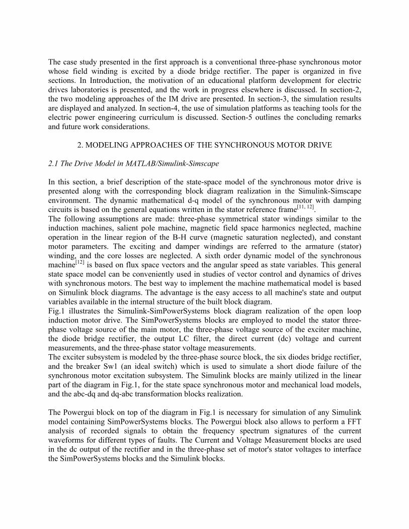
(3) the assigned materials, and (4) the boundary conditions. Once these settings are completed, the mesh is generated and the analysis is completed. The synchronous motor drive simulation results, using the FEA model, are presented in section-3. 2.2.2 Simplorer Implementation of the Synchronous Motor Drive Simulator The electric machines and drives represent complex multi-domain dynamic systems. In this study, the modeling and co-simulation of the overall synchronous motor drive require tools from distinct programming environments. Thus, the ANSYS Maxwell software is employed for the FEA machine model, and ANSYS Simplorer specialized circuit simulator is used to model the exciter's three-phase set of voltages, the power diode bridge rectifier, the three-phase set of voltages feeding the main machine stator windings, and the drive's mechanical load model. Fig.3 illustrates the block diagram realization of the open loop synchronous motor drive for co-simulation in Simplorer-Maxwell (see Fig.1 for comparison, in the first modeling approach).
Fig. 3: Synchronous motor drive block diagram realization in Simplorer/RMxprt-Maxwell

First, the machine model created in RMxprt is exported to Maxwell for a rigorous finite element analysis to generate the expected results. Second, an RMxprt dynamic coupling link allows the FEA machine model created in Maxwell to be imported in Simplorer for co-simulation, and finally, a two way interface is established between Simplorer and Maxwell for the overall electric drive control system implementation and simulation. The drive's normal conditions operation and different failure modes, are similar to those performed using the first approach (Fig.1), and the simulation results are presented in section-3.
3. SIMULATION RESULTS The synchronous motor drive circuit model, contains nonlinear elements such as the circuit breakers and the power electronics components. For this reason the model requires stiff solvers for more accurate numerical simulation using Simulink-SimPowerSystems. In order to achieve the best accuracy and fastest simulation speed the use of the ode23tb solver is recommended to be set in the Simulation Configuration Parameters, with a relative tolerance 10-4, and the Solver reset method set to 'robust', in Simulink. 3.1 Synchronous Motor Drive Model in MATLAB/Simulink-Simscape 3.1.1 Normal Operating Conditions The case study presented in the first modeling approach (section 2.1) is a conventional three-phase synchronous motor whose field winding is excited by a diode bridge rectifier. The motor parameters are given in the reference[10], and the nominal values of this test machine are: Sn = 75 kVA, Vn = 400 V (rms, line-to-line), In = 108 A, nn = 1500 rpm, fn = 50 Hz, 4 poles, and power factor 0.8. The time waveforms of the phase current in amperes, the motor shaft speed in rpm, and the main field excitation flux in Wb, obtained with the simulation platform in MATLAB/Simulink-SimPowerSystems (see Fig.1), are shown in Fig. 4 (a), (b), and (c).
Fig. 4a: Phase current, for drive's normal operating conditions
Fig. 4b: Motor speed, for drive's normal operating conditions

Fig. 4c: Excitation flux, for drive's normal operating conditions
Next, two type of faults are presented and discussed: one fault is due to a faulty power diode of the exciter' s rectifier, and the second one is occurring at the machine terminals.
3.1.2 Diode Bridge Short Circuited The simulation of a fault, due to the short circuit of one of the power diodes, is done in the following way: the synchronous drive is first started under a rated load until it reaches the steady state operation. Then at t=0.5 s, closing the switch Sw1 (see Fig.1), the top diode of the first leg of the bridge rectifier is short circuited. In Fig.5a the waveform of the motor's stator phase current is shown, and in Fig.5b the excitation flux is depicted. The linear state space model of the synchronous drive in Simulink is able to capture the distortion of both waveforms due to the fault occurring after t = 0.5s.
(a)
(b)
Fig. 5: Short circuit of a power diode, at t = 0.5 s, with Simulink-SimPowerSystems (see Fig.1): (a) Phase current; (b) Excitation flux

3.1.3 One Phase To Ground Fault of the Synchronous Motor Fig.6 illustrates the faulted machine's stator phase voltages, currents, and the motor speed, with phase A short-circuited to ground. This simulation is done by starting the drive under rated load. Then, with the motor already running in steady state, at t = 1 s, the switch 2 is opened and the switch Sw3 is simultaneously closed (Fig.1).
(a)
(b)
(c)
Fig. 6: Phase A shorted to ground at the motor's stator terminals: (a) Stator phase voltages, (b) Stator phase currents, (c) Motor speed, with Simulink-SimPowerSystems (see Fig.1)
In this fault condition, with Va = 0, and the increased unbalanced motor currents, the machine cannot operate, the speed is slowing fast and reversing as Fig.6 depicts. 3.2 Synchronous Motor Drive Model using Simplorer/RMxprt-Maxwell The case study presented in this second modeling approach (section 2.2) is a three-phase synchronous motor with field winding. The motor parameters are given in the Solution Data of
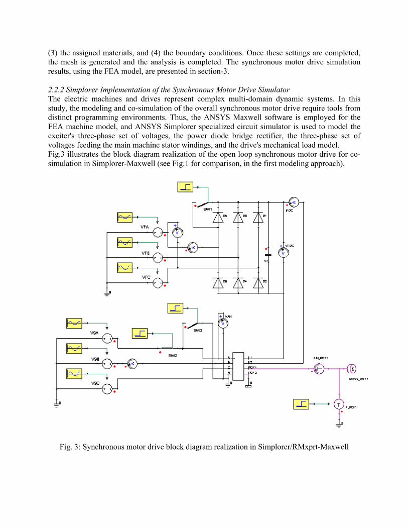
the template example synm3 in the ANSYS-RMxprt motor library. The nominal values of this test machine are: Pn = 538 kW, Vn = 400 V (rms, line-to-line), In = 1.027 kA, nn = 1000 rpm, fn = 50 Hz, 6 poles, and the power factor 0.8. 3.2.1 Normal Operating Conditions The waveforms of the phase and dc excitation currents in amperes, and the motor shaft speed in rad/s, obtained with the co-simulation platform in Simplorer/RMxprt-Maxwell (Fig.3), are shown in Fig. 7.
(a) (b)
(c)
Fig. 7: Normal operating conditions, using Simplorer/RMxprt-Maxwell (see Fig.3): (a) Phase current, in A; (b) DC field current, in A; (c) Speed, in rad/s
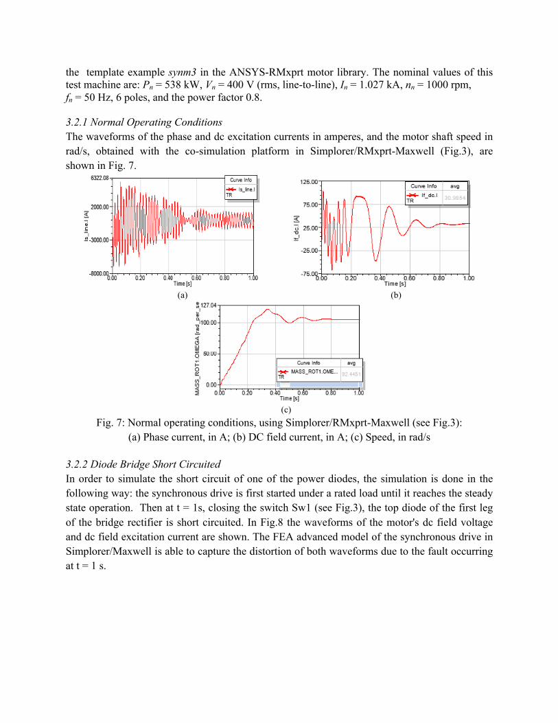
3.2.2 Diode Bridge Short Circuited In order to simulate the short circuit of one of the power diodes, the simulation is done in the following way: the synchronous drive is first started under a rated load until it reaches the steady state operation. Then at t = 1s, closing the switch Sw1 (see Fig.3), the top diode of the first leg of the bridge rectifier is short circuited. In Fig.8 the waveforms of the motor's dc field voltage and dc field excitation current are shown. The FEA advanced model of the synchronous drive in Simplorer/Maxwell is able to capture the distortion of both waveforms due to the fault occurring at t = 1 s.
(a) (b)
Fig. 8: Short circuit of a power diode in Simplorer/RMxprt-Maxwell: (a) Rectifier’s output DC voltage, in kV; (b) DC field current, in A
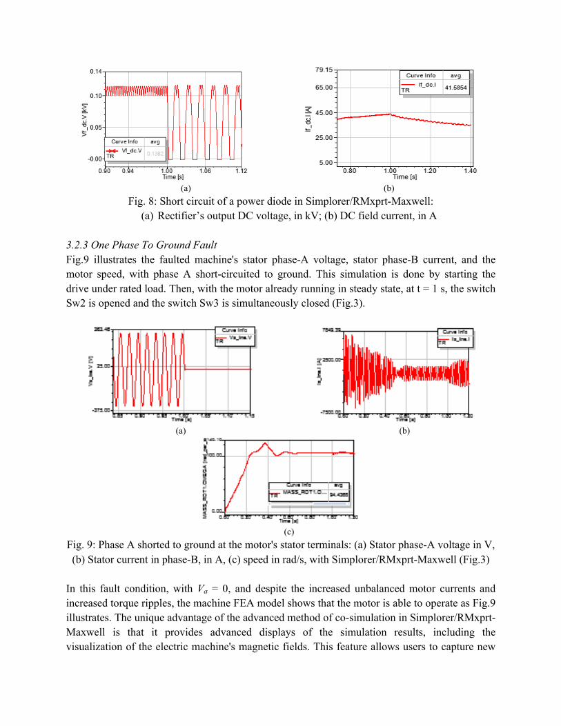
3.2.3 One Phase To Ground Fault Fig.9 illustrates the faulted machine's stator phase-A voltage, stator phase-B current, and the motor speed, with phase A short-circuited to ground. This simulation is done by starting the drive under rated load. Then, with the motor already running in steady state, at t = 1 s, the switch Sw2 is opened and the switch Sw3 is simultaneously closed (Fig.3).
(a) (b)
(c) Fig. 9: Phase A shorted to ground at the motor's stator terminals: (a) Stator phase-A voltage in V, (b) Stator current in phase-B, in A, (c) speed in rad/s, with Simplorer/RMxprt-Maxwell (Fig.3)
In this fault condition, with Va = 0, and despite the increased unbalanced motor currents and increased torque ripples, the machine FEA model shows that the motor is able to operate as Fig.9 illustrates. The unique advantage of the advanced method of co-simulation in Simplorer/RMxprt-Maxwell is that it provides advanced displays of the simulation results, including the visualization of the electric machine's magnetic fields. This feature allows users to capture new

phenomena, including the faults effects on the machine's fields distribution. This would be very difficult to be modeled with the linear simple models. Fig.10 illustrates the magnetic field lines distribution and the magnetic flux density contour plots of the simulated synchronous motor under normal operating conditions.
(a) (b)
Fig. 10: Synchronous motor Maxwell design: (a) Field lines, A [Wb/m], (b) Magnetic flux density, B [T]
4. THE INTEGRATION OF THE SIMULATION PLATFORM
IN POWER ENGINEERING CURRICULUM The proposed simulation platform of the synchronous motor drive will be extended to other ac machines and drives, with the final goal to integrate all into the existent undergraduate and graduate curricula of the Power and Energy Systems program in our university. The simulation platforms will be used for education and training materials in courses such as Electric Drives, and Advanced Electric Drives which are currently taught within the Electric Power and Energy Systems program in our ECE department. 4.1 Integration in Power Systems Undergraduate Curriculum Electric Machines and Drives The Electric Drives course was redesigned during the spring 2012 semester in a new format as a hybrid course (60% face-to-face, 40% online) entitled Electric Machines and Drives. New instructional materials were created based on lecture capturing enhanced technology using the ECHO 360 tool. The simulation platform proposed in this paper, and using Simulink-SimPowerSystems software, will be directly used for teaching and learning models of the three-phase synchronous machines and drives. A new project for the analysis and design of synchronous motor drives is also proposed for the undergraduate Electric Drives course, and based on this simulation platform. In the new project, the students will apply the lectures' theory in an easier and more attractive way to design a scalar control of the synchronous motor drive with enhanced dynamic performance. 4.2 Integration in Power Systems Graduate Curriculum Advanced Electric Drives The simulation platform will be integrated in two stages in the graduate curriculum of the Power and Energy Systems program at our university.
In the first stage, the Maxwell 2D designs of the AC machines FEA models will be directly included in an existent project required within the Advanced Electric Drives course. In addition, the study of possible interactions of Maxwell-Simplorer-Simulink platform with the real-time simulators, such as dSPACE[14], will be performed for electric vehicle applications. In the second stage of the simulation platform integration, 3D Maxwell designs will be generated using the already created 2D designs of the AC machines. The goal, in this case, is to develop the students' necessary skills for high performance electric machine modeling and design. The 3D visualization of the magnetic fields will allow electrical engineering students and professionals to capture new phenomena unseen in the 2D world. Other emerging electric machines and drives can be studied using the simulation platform based on the instructional materials adjusted in accord to the industry’s needs for continuing education. For example, the brushless DC motors (BLDC) and switched reluctance motors (SRM) are two candidates of interest in industry of modern applications such as electric drives for electric vehicles. FEA models developed in Maxwell and coupled with Simplorer will be used to design and analyze these machines. The simulation platform will be extended to include a complete ac-dc-ac back-to-back configuration of the power converters. A new project is proposed, in power quality area, using the co-simulation Maxwell-Simplorer and MATLAB, to model, simulate, and analyze the failures of the exciter's monitoring system of a large power three-phase synchronous motor.
5. CONCLUSION AND FUTURE WORK In this paper, two variants of a simulation platform development for education in the area of ac electric machines and drives were presented. The electrical engineering students and professionals in electric power and energy system fields can build the proposed simulation platforms of the electric machines and drives based on the assumption that the Matlab/Simulink and ANSYS/Maxwell-Simplorer software are available. The main objective of this work is to provide a basis for developing new instructional materials to enhance teaching and learning effectiveness of power engineering courses in educational institutes. The case studies are referring to conventional three-phase large power synchronous motor drives with the main field windings supplied by exciter machines via diode bridge rectifiers. Normal operation, as well as various failure modes, were modeled, and simulation results were presented. One objective in the near future is to post-process the data generated with both simulation platforms presented in this paper, in order to develop online detection algorithms for various faults of power electronics components and of the electric machines as parts of the overall ac drives. Another future research goal is to post-process the data generated by the simulation platforms using the advanced virtual reality visualization and simulation technologies installed in the Center for Innovation through Visualization and Simulation (CIVS) at our university. On this basis, virtual labs will be created for more effective and attractive undergraduate and graduate education in Electric Drives and Power Systems programs.

REFERENCES
[1] Feisel, L. D. and A. J. Rosa, The role of the laboratory in undergraduate engineering education, J. Eng. Educ.,
vol. 94, pp. 121–130, 2005 [2] Magdalena, R., A. J. Serrano, J. D. Martin-Guerrero, A. Rosado, and M. Martinez, A teaching laboratory in
analog electronics: Changes to address the bologna requirements, IEEE Trans. Educ., vol. 51, no. 4, pp. 456–460, Nov. 2008
[3] Lipo, Th. A, Introduction To AC Machine Design, WPERC, University of Wisconsin-Madison, 2007, ISBN 0-9745470-2-6
[4] Gray, D.L, Zhang, Ziang, Apostoaia, C.M., Xu Chang, A Neural Network based Approach for the Detection of Faults in the Brushless Excitation of a Synchronous Motor, 2009 IEEE International Conference on Electro/Information Technology, June 7-9, 2009, University of Windsor, Ontario, Canada.
[5] Apostoaia, C.M. Co-Simulation Platform for AC Drives Control Systems, WASET 2012-ICEMDS International Conference on Electric Machines and Drive Systems, Issue 71, pp.1879-1886, Paris, France, November 28-29, 2012
[6] Apostoaia, C.M., AC Machines and Drives Simulation Platform, IEMDC 2013 - IEEE International Electric Machines and Drives Conference, Chicago, IL, May 12-15, 2013
[7] MATLAB®/Simulink® are registered trademarks of the Mathworks, Inc. [8] ANSYS-RMxprt and ANSYS-Maxwell, components of ANSYS (Ansoft) software, USA, ANSYS Maxwell 2D
User’s Guide, v.15 [9] ANSYS-Simplorer, software component of ANSYS (Ansoft), USA, User’s Guide, v.10 [10] Barakat, A., Tnani, S., Champenois, G., and Mouni, E., Analysis of synchronous machine modeling for
simulation and industrial applications, Elsevier, Simulation Modelling Practice and Theory 18 (2010), pp.1382-1396.
[11] Kelemen, A. and Maria Imecs, Vector Control of AC Drives, OMIKK, Budapest, vol.2, 1992, ISBN 963-593-140-9
[12] Maria Imecs,Szabo, C., and Incze, J.J., Stator-Field-oriented Control of the Variable-excited Synchronous Motor: Numerical Simulation, 7thInternational Symposium of Hungarian Researchers on Computational Intelligence, pp.95-105, 2010
[13] Boldea, I. and Tutelea, L., Electric Machines-Steady State, Transients, and Design with MATLAB, C.R.C. Press, 2010, ISBN 978-1-4200-5572-6
[14] dSPACE, manufacturer of tools for the development of mechatronic controls. Website: http://www.dspace.com/en/inc/home.cfm.