54312282 design report team mustangs 25920
DESCRIPTION
baja design reportTRANSCRIPT
BAJA SAEINDIA 2011 Design Report
Team Registration ID: 25920
Author: Team mustangs Co-Author: Prof. D.B.jani
Author E-Mail: [email protected]
2 | P a g e
Introduction
The designing considerations of our buggy were dependent on, the actual task to be carried out by the vehicle (i.e. it’s off road capability), the rules to be followed during making it and the most important point- it should be a competitive product easily manufacturable, value for money and pleasing to the costumers. As with any engineering design project teams must also place a large emphasis on gaining financial support and managing that project within the budget.
Technical Specifications
Engine LOMBARDINI LGA 340-11HP, 44Ah, four stroke air cooled,
1300+/- 100 RPM
Dimensions
Overall length, width, height
105 in, 63 in, 60.5 in
Wheelbase & Track
63 in, 58.26 in
Drive Train
Transmission Mahindra Alfa Champion
Gear Ratio High speed – 7.35:1, Low speed – 31.48:1
Suspension & Wheel
Front Rear
Suspension Type
Double wishbone SLA type
Double wishbone SLA type
Rims 12 inch diameter
Tyre Size 5.00X12 5.00X12
Brakes Hydraulic operated disc
brakes
Hydraulic operated disc
brakes
Steering Rack and pinion type
Mass Sprung Unsprung
Approx. 280 kg 64 kg
Target Vehicle Performance
Max Speed 50.37 kmph
Gradiability 49.75%(26.45 deg)
Acceleration 1.38 m/s2
Stopping dist. 21.32 m
Deceleration 5.89 m/s2
Turning Radius 3.8 m
Ground Clearance 280 mm
Fuel Consumption 10 kmpl
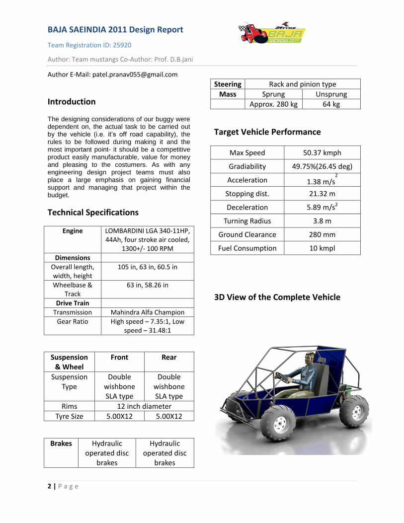
3D View of the Complete Vehicle
Page | 3
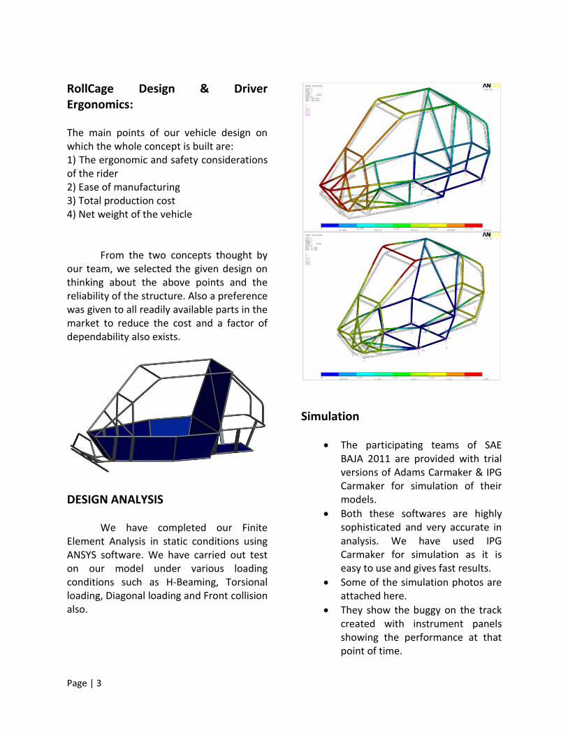
RollCage Design & Driver Ergonomics: The main points of our vehicle design on which the whole concept is built are: 1) The ergonomic and safety considerations of the rider 2) Ease of manufacturing 3) Total production cost 4) Net weight of the vehicle
From the two concepts thought by our team, we selected the given design on thinking about the above points and the reliability of the structure. Also a preference was given to all readily available parts in the market to reduce the cost and a factor of dependability also exists.
DESIGN ANALYSIS We have completed our Finite
Element Analysis in static conditions using ANSYS software. We have carried out test on our model under various loading conditions such as H-Beaming, Torsional loading, Diagonal loading and Front collision also.
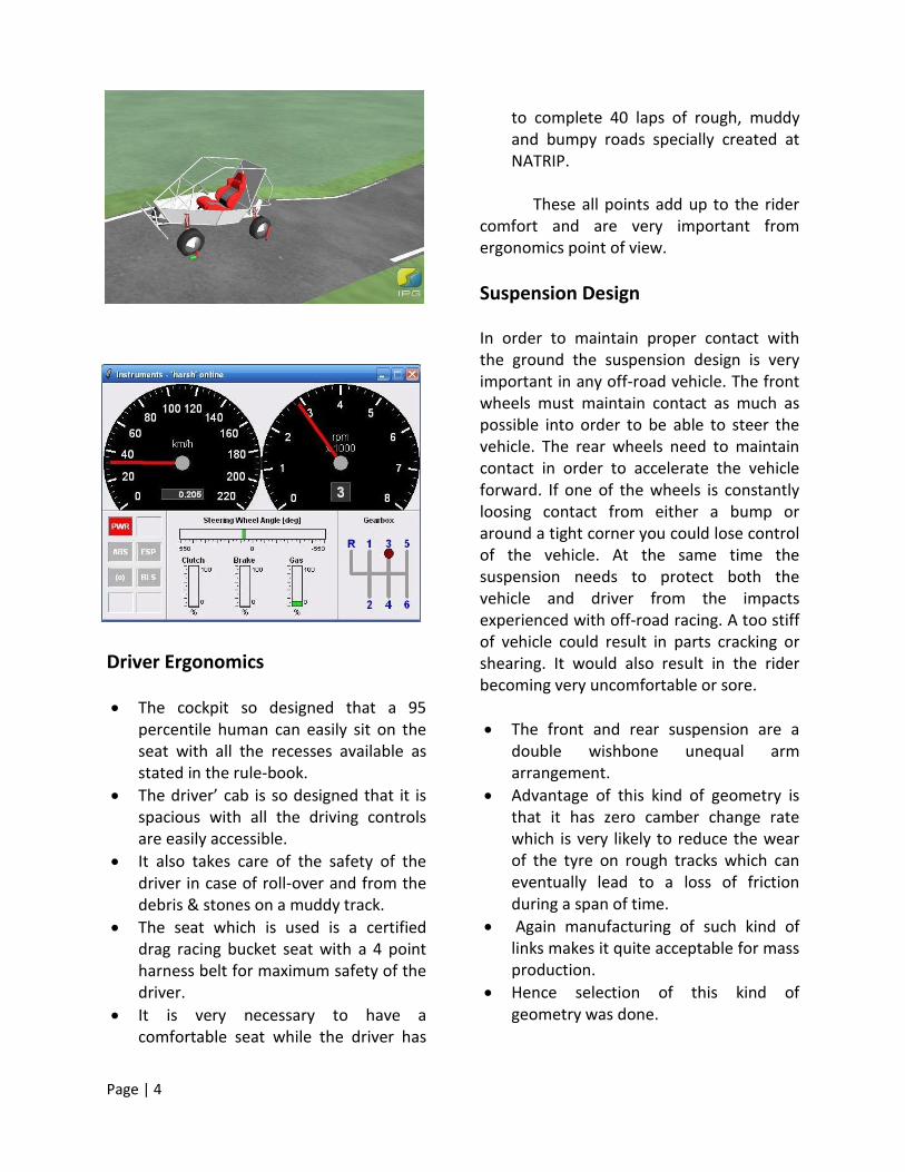
Simulation
The participating teams of SAE BAJA 2011 are provided with trial versions of Adams Carmaker & IPG Carmaker for simulation of their models.
Both these softwares are highly sophisticated and very accurate in analysis. We have used IPG Carmaker for simulation as it is easy to use and gives fast results.
Some of the simulation photos are attached here.
They show the buggy on the track created with instrument panels showing the performance at that point of time.
Page | 4
Driver Ergonomics
The cockpit so designed that a 95 percentile human can easily sit on the seat with all the recesses available as stated in the rule-book.
The driver’ cab is so designed that it is spacious with all the driving controls are easily accessible.
It also takes care of the safety of the driver in case of roll-over and from the debris & stones on a muddy track.
The seat which is used is a certified drag racing bucket seat with a 4 point harness belt for maximum safety of the driver.
It is very necessary to have a comfortable seat while the driver has
to complete 40 laps of rough, muddy and bumpy roads specially created at NATRIP.
These all points add up to the rider
comfort and are very important from ergonomics point of view.
Suspension Design In order to maintain proper contact with the ground the suspension design is very important in any off-road vehicle. The front wheels must maintain contact as much as possible into order to be able to steer the vehicle. The rear wheels need to maintain contact in order to accelerate the vehicle forward. If one of the wheels is constantly loosing contact from either a bump or around a tight corner you could lose control of the vehicle. At the same time the suspension needs to protect both the vehicle and driver from the impacts experienced with off-road racing. A too stiff of vehicle could result in parts cracking or shearing. It would also result in the rider becoming very uncomfortable or sore.
The front and rear suspension are a double wishbone unequal arm arrangement.
Advantage of this kind of geometry is that it has zero camber change rate which is very likely to reduce the wear of the tyre on rough tracks which can eventually lead to a loss of friction during a span of time.
Again manufacturing of such kind of links makes it quite acceptable for mass production.
Hence selection of this kind of geometry was done.
Page | 5
Generally in cars camber and toe setting are adjustable.
But in our vehicle caster setting is also adjustable including camber and toe in-out.
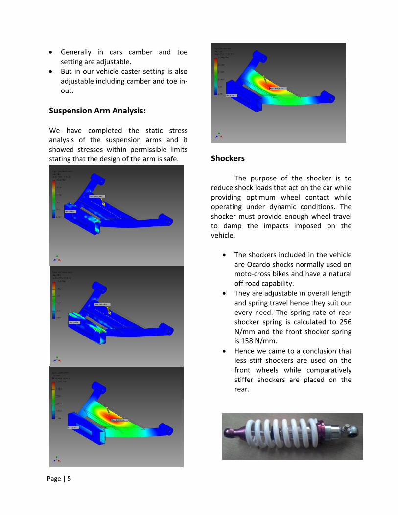
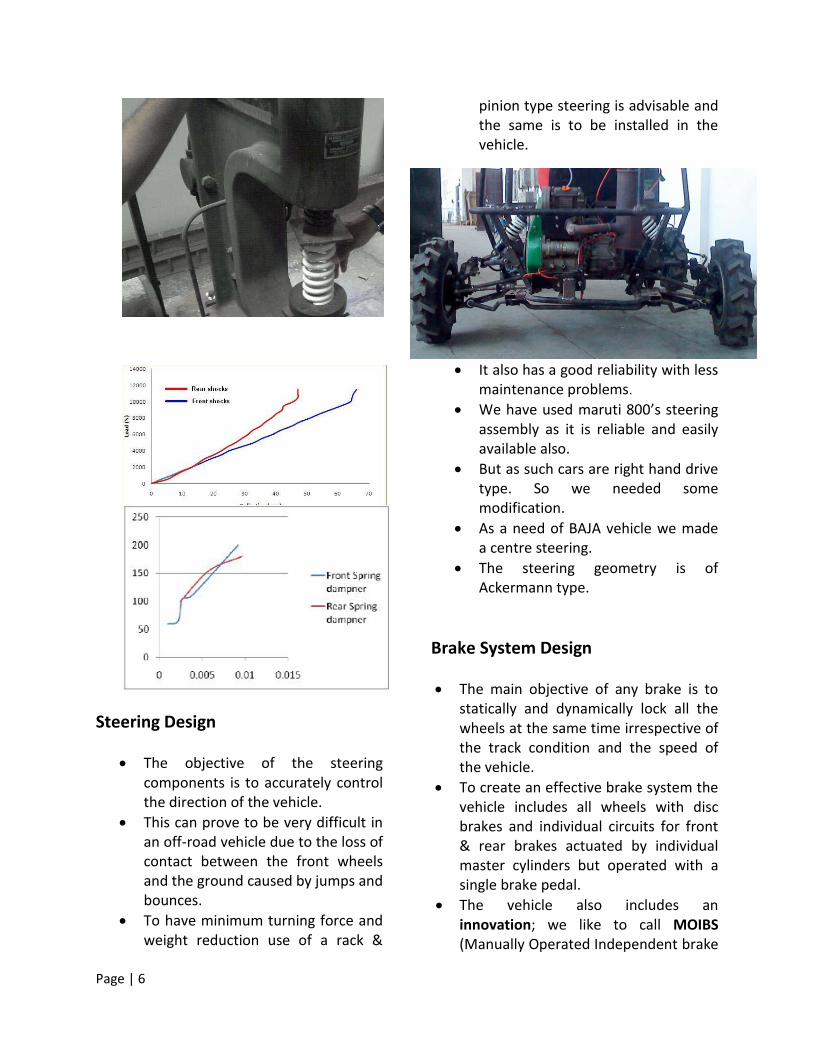
Suspension Arm Analysis: We have completed the static stress analysis of the suspension arms and it showed stresses within permissible limits stating that the design of the arm is safe.
Shockers
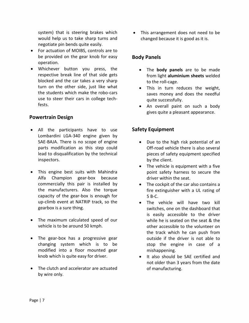
The purpose of the shocker is to reduce shock loads that act on the car while providing optimum wheel contact while operating under dynamic conditions. The shocker must provide enough wheel travel to damp the impacts imposed on the vehicle.
The shockers included in the vehicle are Ocardo shocks normally used on moto-cross bikes and have a natural off road capability.
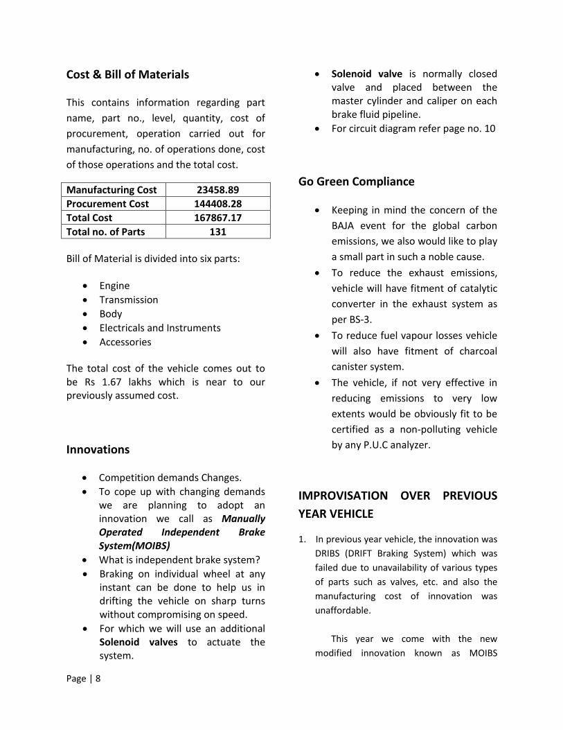
They are adjustable in overall length and spring travel hence they suit our every need. The spring rate of rear shocker spring is calculated to 256 N/mm and the front shocker spring is 158 N/mm.
Hence we came to a conclusion that less stiff shockers are used on the front wheels while comparatively stiffer shockers are placed on the rear.
Page | 6
Steering Design
The objective of the steering components is to accurately control the direction of the vehicle.
This can prove to be very difficult in an off-road vehicle due to the loss of contact between the front wheels and the ground caused by jumps and bounces.
To have minimum turning force and weight reduction use of a rack &
pinion type steering is advisable and the same is to be installed in the vehicle.
It also has a good reliability with less maintenance problems.
We have used maruti 800’s steering assembly as it is reliable and easily available also.
But as such cars are right hand drive type. So we needed some modification.
As a need of BAJA vehicle we made a centre steering.
The steering geometry is of Ackermann type.
Brake System Design
The main objective of any brake is to statically and dynamically lock all the wheels at the same time irrespective of the track condition and the speed of the vehicle.
To create an effective brake system the vehicle includes all wheels with disc brakes and individual circuits for front & rear brakes actuated by individual master cylinders but operated with a single brake pedal.
The vehicle also includes an innovation; we like to call MOIBS (Manually Operated Independent brake
Page | 7
system) that is steering brakes which would help us to take sharp turns and negotiate pin bends quite easily.
For actuation of MOIBS, controls are to be provided on the gear knob for easy operation.
Whichever button you press, the respective break line of that side gets blocked and the car takes a very sharp turn on the other side, just like what the students which make the robo-cars use to steer their cars in college tech-fests.
Powertrain Design
All the participants have to use Lombardini LGA-340 engine given by SAE-BAJA. There is no scope of engine parts modification as this step could lead to disqualification by the technical inspectors.
This engine best suits with Mahindra Alfa Champion gear-box because commercially this pair is installed by the manufacturers. Also the torque capacity of the gear-box is enough for up-climb event at NATRIP track, so the gearbox is a sure thing.
The maximum calculated speed of our vehicle is to be around 50 kmph.
The gear-box has a progressive gear changing system which is to be modified into a floor mounted gear knob which is quite easy for driver.
The clutch and accelerator are actuated by wire only.
This arrangement does not need to be changed because it is good as it is.
Body Panels
The body panels are to be made from light aluminium sheets welded to the roll-cage.
This in turn reduces the weight, saves money and does the needful quite successfully.
An overall paint on such a body gives quite a pleasant appearance.
Safety Equipment
Due to the high risk potential of an Off-road vehicle there is also several pieces of safety equipment specified by the client.
The vehicle is equipment with a five point safety harness to secure the driver within the seat.
The cockpit of the car also contains a fire extinguisher with a UL rating of 5 B-C.
The vehicle will have two kill switches, one on the dashboard that is easily accessible to the driver while he is seated on the seat & the other accessible to the volunteer on the track which he can push from outside if the driver is not able to stop the engine in case of a mishappening.
It also should be SAE certified and not older than 3 years from the date of manufacturing.
Page | 8
Cost & Bill of Materials This contains information regarding part
name, part no., level, quantity, cost of
procurement, operation carried out for
manufacturing, no. of operations done, cost
of those operations and the total cost.
Manufacturing Cost 23458.89
Procurement Cost 144408.28
Total Cost 167867.17
Total no. of Parts 131
Bill of Material is divided into six parts:
Engine
Transmission
Body
Electricals and Instruments
Accessories
The total cost of the vehicle comes out to be Rs 1.67 lakhs which is near to our previously assumed cost.
Innovations
Competition demands Changes.
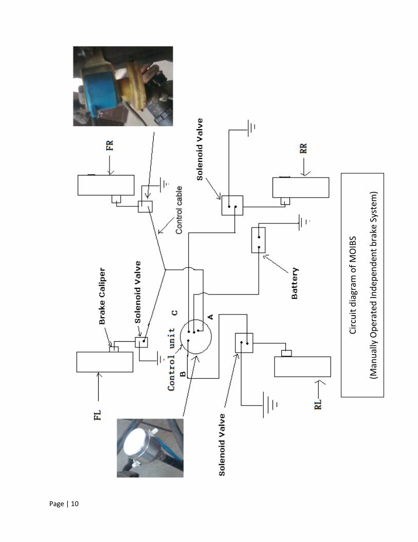
To cope up with changing demands we are planning to adopt an innovation we call as Manually Operated Independent Brake System(MOIBS)
What is independent brake system?
Braking on individual wheel at any instant can be done to help us in drifting the vehicle on sharp turns without compromising on speed.
For which we will use an additional Solenoid valves to actuate the system.
Solenoid valve is normally closed valve and placed between the master cylinder and caliper on each brake fluid pipeline.
For circuit diagram refer page no. 10
Go Green Compliance
Keeping in mind the concern of the
BAJA event for the global carbon
emissions, we also would like to play
a small part in such a noble cause.
To reduce the exhaust emissions,
vehicle will have fitment of catalytic
converter in the exhaust system as
per BS-3.
To reduce fuel vapour losses vehicle
will also have fitment of charcoal
canister system.
The vehicle, if not very effective in
reducing emissions to very low
extents would be obviously fit to be
certified as a non-polluting vehicle
by any P.U.C analyzer.
IMPROVISATION OVER PREVIOUS
YEAR VEHICLE
1. In previous year vehicle, the innovation was
DRIBS (DRIFT Braking System) which was
failed due to unavailability of various types
of parts such as valves, etc. and also the
manufacturing cost of innovation was
unaffordable.
This year we come with the new
modified innovation known as MOIBS
Page | 9
(Manually Operated Independent Brake
System) which is successfully mounted on
our vehicle and works accurately and the
most exciting thing is that it is easily
available in the market with affordable
price.
2. In previous year vehicle, the wheel
alignment parameters were fixed and after
some experiment we concluded that it must
be adjustable to enhance the performance
of steering geometry.
This time these parameter are fully
adjustable (including caster adjustment) to
increase the stability, direction control
consideration of a vehicle.
3. In the previous year vehicle, there was
some problem with top gear, it was not
working because our tyre selection was not
good and as well as loss of more power in
the engine.
This year we completely change the
gear shifting mechanism as well as choice of
proper tyre size which suits the torque-
speed curve of the engine considering
transmission ratio. So, the trouble with the
fourth gear is eliminated.
4. In the last year, the output shaft angle with
the horizontal axis was greater than 20’,
this caused a lot of power loss of the engine.
Thus, its overall efficiency was reduced.
Here, we achieved an angle less than
20’(app 17) with the horizontal axis. Thus
overall power loss is reduced and we
obtained a desired output.
5. In previous year vehicle, we used 2
different dimensions for tyres in front and
rear. The configuration of wheel tyres were
21” 7-10 and 22” 11-10 for front & rear
respectively and it was imported from China
that increased the overall cost of the
vehicle and the most important thing is that
the configuration of tyre was not suitable to
the brake disc-caliper assembly and also its
modification was quite tough.
This year we come with the MRF
SHAKTI-TF type that does not require any
modification on it and it successfully fitted
to the wheel. The dimensions of our type
are 22” 5-12 here the dimension of all the
four wheels is analogous.
6. In previous year vehicle, the placement of
the cables of clutch and acceleration was
not proper. So, cables got broke on the
track due to shearing failure.
This time we have done proper
placement of these cables.
7. In previous year vehicle, the band radius
exhaust pipe was quite large, it caused
more heating to the surface and made the
exhaust pipe broke.
This year we modified the bend radius of
exhaust pipe as per the requirement. Hence,
it is under the factor of safety.
References & Acknowledgment
Vehicle Dynamics, By Thomas D. Gillespie
Race Car Vehicle Dynamics , By Milliken & Milliken
SAE lecture notes, by Richard B. Hathaway
Page | 10
Cir
cuit
dia
gram
of
MO
IBS
(Man
ual
ly O
per
ated
Ind
epen
den
t b
rake
Sys
tem
)