5.5 plc programming - freetwanclik.free.fr/electricity/iepopdf/1081ch5_5.pdf · plc is an acronym...
TRANSCRIPT

944
5.5 PLC Programming
V. A. BHAVSAR (2005)
Costs of Programming: PLC programming cost depends on the complexity and the length of the project. Thehourly rate of programming is between $40 and $80. Typically, the programming costis 50 to 100% or more of the hardware cost depending on the size and complexityof the PLC system.
Partial List of Suppliers: Most PLC manufacturers also do programming for their clients or they have systemsintegrators who can do the programming for them. Listed below are some of themajor PLC manufacturers:
ABB (www.abb.com)Allen-Bradley (www.ab.com)GE Fanuc (www.gefanuc.com) Klockner-Moeller (www.km-medialab.com) Mitsubishi (www.mitsubishielectric.com) Modicon (www.modicon.com) Omron (www.omron.com) Siemens (www.siemens.com) Triconex (www.triconex.com)
INTRODUCTION
This section covers the basics of PLC programming. It pro-vides the readers with enough information about PLC systemhardware and programming techniques to enable them towrite simple programs and understand complex programs. Itstarts with a basic understanding of PLC, followed by anintroduction to major hardware components and operation ofPLC system, and various programming languages available.
The main focus of this section is on ladder logic, whichis the most widely used PLC language. The rest of the sectiongives details about basic ladder logic instructions, program-ming devices used to write ladder logic, ladder logic struc-ture, how to develop ladder logic and program a PLC, pro-gramming considerations, and documentation. The sectionconcludes with a typical ladder logic program example andrecent developments in PLC programming.
What Is a PLC?
PLC is an acronym for programmable logic controller. It isalso known by such other names as programmable controlleror logic controller. Basically, a PLC is an electronic devicethat was invented to replace the electro-mechanical relaylogic circuits used for machine automation in the automobileindustry. It was first introduced in late 1960s by BedfordAssociates as Modular Digital Controller (MODICON) to a
major U.S. car manufacturer. Modern definition of PLCs:They are small computers, dedicated to automation tasks inan industrial environment.
There are three major kinds of PLCs:
Compact PLC: Monolithic construction, monoproces-sor, fixed number of I/Os
Modular PLC: Modular construction, one or multipro-cessor, expandable I/Os
Soft-PLC: Windows NT- or CE-based, direct use ofCPU or coprocessors
Today, PLCs are used in many industries includingmachining, packaging, material handling, automated assembly,and countless others. Usually PLC manufacturers provide theircustomers with various applications of their products. Otheruseful sources to learn more about existing and new PLCapplications are technical journals, magazines, and papers pub-lished on control and automation.
SYSTEM HARDWARE AND OPERATION1
A modular PLC system consists of the following major com-ponents:
• Rack• Power supply module
© 2006 by Béla Lipták

5.5 PLC Programming 945
• CPU (processor/memory)• I/O modules• Programming device
Figure 5.5a shows a typical modular PLC system.A PLC is a sequential device; i.e., it performs one task
after another. Figure 5.5b shows how a conventional PLCsystem operates. There are three major tasks that a PLCperforms, in the following order:
• Task 1: Read inputs. PLC checks status of its inputsto see if they are on or off and updates its memorywith their current value.
• Task 2: Program execution. PLC executes programinstructions one by one sequentially and stores theresults of program execution in the memory for uselater in task 3.
• Task 3: Write outputs. PLC updates status of its out-puts based on the results of program execution storedin task 2.
After PLC executes task 3 it goes back to execute task 1again. The total time taken by a PLC to perform these threetasks is called the PLC scan time. Scan time depends on CPUclock speed, user program length, and number of I/Os. Typ-ically scan time is in milliseconds. The smaller the scan time,the faster the updates of the I/O and the program execution.
FIG. 5.5aModular PLC system.
CPUDigitalinput
module
Digitaloutputmodule
Analoginput
module
110 VACor
220 VACPush buttons,switches etc.
Relays, lights,solenoids etc.
5-Slot rack
Programming device
Analogoutputmodule
Transmitteretc.
Controlvalve etc.
Powersupplymodule
FIG. 5.5bPLC operation.
Inputmemory
Outputmemory
PROGRAM
Inputmodule
(field inputs)
CPU
Task 1 Task 2 Task 3
Outputmodule
(field outputs)
Task 2Execute program
Task 3Write output status
Scan time
Task 1Read input status
© 2006 by Béla Lipták

946 PLCs and Other Logic Devices
As a general guide, PLC scan time should be less than halfthe time it takes the fastest changing input signal to changein the system.
The following are the functions of a PLC:
Measure: Measure process values, both discrete andcontinuous
Command: Execute logic and control programsRegulation: Control field devicesCommunication: Communicate with other PLCs,
remote I/Os, MMIs, and other network peripherals
PROGRAMMING LANGUAGES
The two forms of PLC programming languages are text andgraphic languages:
Text languages are the instruction list (IL) and the struc-tured text (ST) types. The graphic languages are the sequen-tial function charts (SFCs), function block diagrams (FBDs),and the ladder logic types.
Different PLCs support one or more of the above lan-guages for programming. These languages have their advan-tages and limitations, and they complement one another toprovide programmers with more programming power. A briefunderstanding of these languages is given below, followedby a detailed understanding of ladder logic.
Instruction List
Instruction list is a low-level language. It is mainly used forsmaller applications or for optimizing parts of an application.IL is one of the languages for the description of the actionswithin the steps and conditions attached to the transitions ofthe SFC language (this is discussed in more detail later).Instructions always relate to the current result (or IL registervalue). The operator indicates the operation that must be per-formed on the current value of the IL register and the operand.The result of the operation is stored again in the IL register.
An IL program is a list of instructions. Each instructionmust begin on a new line and must contain an operator and,if necessary, for the specific operation, one or more operands,separated with commas (,). A label followed by a colon (:) mayprecede the instruction. If a comment is attached to the instruc-tion, it must be the last component of the line. Commentsalways begin with (* and end with *). Empty lines may beentered between instructions. Comments may be put on emptylines. Listed below are examples of instruction lines:
Structured Text
Structured text is a high-level structured language designed forautomation processes. This language is mainly used to imple-ment complex procedures that cannot be easily expressed withgraphic languages. ST is one of the languages for the descrip-tion of the actions within the steps and conditions attached tothe transitions of the SFC language (this is discussed in moredetail later). An ST program is a list of ST statements. Eachstatement ends with a semicolon (;) separator. Comments maybe freely inserted into the text. A comment must begin with(* and end with *). The basic types of ST statements are
• Assignment statement (variable := expression;)• Subprogram or function call• Function block call• Selection statements (IF, THEN, ELSE, CASE ...)• Iteration statements (FOR, WHILE, REPEAT ...)• Control statements (RETURN, EXIT ...)• Special statements for links with other languages such
as SFC
Sequential Function Charts
Sequential function chart is a language used to graphicallydescribe sequential operations. The process is represented asa set of well-defined steps, linked by transitions. A sequenceof steps is called a task, and many such tasks make up thewhole process. Figure 5.5c shows basic components (graphic
Label Operator Operand Comments
Start: LD IN1 (* start pushbutton *)
AND MD1 (* mode is manual *)
ST Q2 (* start motor *)
LD-Load, ST-StoveFIG. 5.5cBasic components of SFC language.
Stepnumber
Step comment
Actions within thestep
(IL, ST, call to otherSFC, functions and
function blocks)
Stepnumber
Conditions fortransition
(IL, ST or LD)
Initial stepindicator
Steps
Transition number
1
2
Step comment
Actions within thestep
(IL, ST, call to otherSFC, functions and
function blocks)
© 2006 by Béla Lipták

5.5 PLC Programming 947
symbols) of the SFC language: steps and initial steps, tran-sitions, and links between steps and transitions.
An SFC program is activated by the system when theapplication starts. At run time, the step that is active is high-lighted. When program execution starts, the initial stepbecomes the current step by default. When the conditions fortransition become true, the sequence advances to the next stepin the sequence. Actions within the step can be Boolean, STor IL statements, calls to other SFCs, or function blocks orfunctions. A Boolean condition is attached to each transitionusing other languages, such as ST, IL, or ladder logic (LD).
Function Block Diagrams
The functional block diagram (FBD) is a language used tographically build complex procedures by taking existingfunctions and wiring them together. Figure 5.5d shows basiccomponents (graphic symbols) of the FBD language. An FBDdiagram describes a function between input variables andoutput variables. A function is described as a set of elemen-tary function blocks. Input and output variables are connectedto blocks by connection lines. An output of a function blockmay also be connected to an input of another block.
Each function block has a fixed number of input connec-tion points and a fixed number of output connection points.A function block is represented by a single rectangle. Theinputs are connected on its left border. The outputs are con-nected on its right border. An elementary function blockperforms a single function between its inputs and its outputs.The name of the function to be performed by the block iswritten in its rectangle symbol. Each input or output of ablock has a well-defined type. Input variables of an FBDprogram must be connected to input connection points offunction blocks.
The type of each variable must be the same as the typeexpected for the associated input. An input for an FBD
diagram can be a constant expression, any internal or inputvariable, or an output variable. Output variables of an FBDprogram must be connected to output connection points offunction blocks. The type of each variable must be the sameas the type expected for the associated block output. Anoutput for an FBD diagram can be any internal or outputvariable, or the name of the program (for subprograms only).When an output is the name of the currently edited subpro-gram, it represents the assignment of the return value for thesubprogram (returned to the calling program).
LADDER LOGIC PROGRAMMING
Ladder logic is one of the most popular and widely usedprogramming languages by electricians and programmers,since it emulates the old relay-based ladder logic structure.For this reason, the rest of this section discusses ladder logicprogramming in greater detail.
Ladder Logic Structure
As ladder logic is an extension of the relay logic, it makessense to see how the ladder logic and relay logic structuresare analogous to each other. Also, a basic understanding ofBoolean logic will help in writing ladder logic, since manytimes a control scheme is first developed using Boolean logicand then converted into a ladder logic in PLC. Figure 5.5eshows three different representations of a simple logic forstarting/stopping a motor.
In relay logic, the lines L1 and L2 represent the powerapplied to the relay circuit. Start pushbutton is normally opentype and stop pushbutton is normally closed type. When thestart pushbutton is pressed, the start pushbutton’s contactcloses, the current flows through start and stop pushbuttons’contacts to the relay coil, and it energizes the relay coil. Thecontact of the relay coil gets closed and provides an alternatecurrent path to the relay coil, thus keeping it energized. Whenthe stop pushbutton is pressed, the stop pushbutton’s contactopens, the current path to the relay is opened, the relay getsde-energized, and the relay contact opens. The motor runs aslong as the motor relay stays energized.
In Boolean logic, the start pushbutton and motor relaycontact are represented as inputs to the OR logic block, outputof the OR logic block and stop pushbutton are representedas inputs to the AND logic block, and motor relay coil isrepresented as output of the AND logic block. Normallyclosed stop pushbutton is shown by inverting the stop input(logical 1). When the start pushbutton is pressed (logical 1),output of the OR block becomes logical 1. With both inputsof the AND block being logical 1, output of the AND blockbecomes logical 1 and turns the motor relay on. Status ofmotor relay is fed back to the OR block to keep its outputon. Motor relay turns off as soon as the stop button is pressed.
In PLC ladder logic, two vertical lines represent virtualpower lines, and the actual electrical current is replaced by
FIG. 5.5dBasic components of FBD language.
Function
Inputs
Outputs
Elementaryfunction blocks
Name ofthe
function(e.g. OR)
Name ofthe
function(e.g. XOR)
Name ofthe
function(e.g. AND)
© 2006 by Béla Lipták

948 PLCs and Other Logic Devices
logical path. A horizontal line represents a logical rung.Inputs are shown near the left vertical line and outputs areshown near the right vertical line on a rung. When the inputshave logical 1 or TRUE state, logical path to the outputscompletes, and outputs get logical 1 or TRUE state.
In this example, start and stop pushbutton contacts areshown as inputs that represent the physical pushbuttons con-nected to the PLC input module. Inputs have their PLC mem-ory addresses where their current values are stored (here theyare 001 and 002). As the pushbuttons are operated, the PLCmemory is updated with their current status. An open contactrepresents logical 0 or FALSE, and a closed contact repre-sents logical 1 or TRUE in PLC memory. In this example therelay coil is shown as an internal coil (PLC memory address017) that represents a physical relay connected to the PLCoutput module. As the internal coil’s status changes based onthe pushbuttons status, PLC memory is updated with theinternal coil’s current status.
An energized internal coil represents logical 1 and a de-energized internal coil represents logical 0 in PLC memory.
The physical relay coil gets energized when the PLC internalcoil is energized (logical 1) and de-energized when the PLCinternal coil is de-energized (logical 0). The internal coil hasa large number of virtual contacts limited only by the PLCmemory capacity.
Ladder Logic Programming Basic Instructions
Figure 5.5f and Figure 5.5g show graphical symbols of ladderlogic basic instructions discussed below.
Contact This is an input instruction. It can be used torepresent an external digital input or a contact of internal(soft) relay. There are two basic types of contacts:
1. Normally open contact (NO) is used to represent aninput signal that is normally off and will become onwhen operated, e.g., a physically connected pushbut-ton with normally open contact. For an NO contact,logical 0 represents OFF or FALSE condition andlogical 1 represents ON or TRUE condition.
2. Normally closed contact (NC) is used to represent aninput signal that is normally on and will become offwhen operated, e.g. a normally closed contact of aninternal (soft) relay coil. For an NC contact, logical 0represents ON or TRUE condition and logical 1 rep-resents OFF or FALSE condition.
Coil This is an output instruction. It can be used to repre-sent an external digital output or an internal (soft) relay. Thereare two basic types of coils:
1. Normally de-energized coil is used to represent anoutput signal that is normally off or de-energized andwill become on or energized when all inputs on a rungpreceding this coil are TRUE.
2. Normally energized coil is used to represent an outputsignal that is normally on or energized and willbecome off or de-energized when all inputs on a rungpreceding this coil are TRUE.
Timer This is a timing instruction. Timer is used to delay anevent or to time an event. Generally, a timer instruction hasenable input, preset time value, elapsed time value, and anoutput signal. Preset and elapsed times are stored in PLC mem-ory registers. There are two basic types of timers. Figure 5.5hshows the timing diagram for these timers.
1. On-delay timer is used to delay turning on an output.When the enable condition becomes true, timer startstiming, its current time value starts to go up, and afterits current time reaches the preset time value, outputof the timer is turned on. Output stays on as long asthe enable input signal is on. As soon as the enablesignal becomes false or logical 0, the output goes off
FIG. 5.5eThree types of logic representation.
Boolean logic
Start
Stop
Outputto motorOR
AND
PLC internalcoil
017
Start001
Stop002
PLC virtual powerlines
017
PLC logic
Relay logic
Motor relaycoil
Startpush button
Stoppush button
Motor relaycontact
M
110 V AC OR220 VAC
L1 L2
M
© 2006 by Béla Lipták

5.5 PLC Programming 949
and the timer current value becomes 0. There are othervariations of timers that have a reset input connectionto reset the timer current value.
2. Off-delay timer is used to delay turning off an output.As soon as the enable condition becomes true, outputof the timer turns on. When the enable conditionbecomes false or logical 0, timer starts timing and itscurrent time value starts to go up. Timer output stayson until its current time reaches the preset time value.As soon as the timer current time reaches the presettime, its output goes off and the timer stops timingand its current value stops increasing. When enableinput becomes true the next time, timer current valueis reset to 0.
Counter This is a counting instruction. Counter is used tocount the number of occurrences of an event. Generally, acounter instruction has enable input, preset count value, accu-mulated count value, reset input, and an output signal. Preset
and accumulated counts are stored in PLC memory registers.There are two basic types of counters. Figure 5.5i shows atiming diagram for these counters.
1. Up-counter is used to count up. When the enable con-dition becomes true, i.e., transitions from logical 0 tological 1, the counter accumulated value is incrementedby 1. Every time this transition takes place, the counteraccumulated value increases by 1. When the accumu-lated value reaches the preset value, the counter outputturns on. Output stays on until the counter is reset.
2. Down-counter is used to count down. Counter accu-mulated is set at the preset value. When the enablecondition becomes true, i.e., transitions from logical0 to logical 1, the counter accumulated value is dec-remented by 1. Every time this transition takes place,the counter accumulated value decreases by 1. Whenthe accumulated value reaches 0, counter output turnson. Output stays on until the counter is reset.
FIG. 5.5fPLC ladder logic instruction symbols.
Mathematics
Normally opencontact
Normally closedcontact
Contacts
CoilsNormally
de-energizedcoil
Normallyenergized
coil
OutputEnable OutputEnable
Reset
Timer Counter
Timer
Preset
Current
Counter
Preset
Accumulated
Enable
Input 1
Input 2
Output
SUB
Enable
Input 1
Input 2
Output
MUL
Enable
Input 1
Input 2
Output
DIV
Enable
Input 1
Input 2
Output
ADD
© 2006 by Béla Lipták

950 PLCs and Other Logic Devices
Mathematics Math instructions are used for data manipu-lations. Generally, a math instruction has enable input, twodata inputs, and one output. Data inputs are register locationsor constants and output is a register location where the resultof the math operation is stored. There are four basic types ofmath instructions:
1. ADD is used to perform addition. When the enablecondition becomes true, input 2 data are added to input1 data and the result is stored in output.
2. SUB is used to perform subtraction. When the enablecondition becomes true, input 2 data are subtractedfrom input 1 data and the result is stored in output.
3. MUL is used to perform multiplication. When theenable condition becomes true, input 1 data are multi-plied with input 2 data and the result is stored in output.
4. DIV is used to perform division. When the enablecondition becomes true, input 1 data are divided byinput 2 data and the result is stored in output.
Although most advanced PLCs support real math, somePLCs only support integer math, i.e., math performed oninteger numbers. Hence, when you perform division on inte-gers, the result is an integer and loose remainder (fraction partof the result). To deal with this, you must first multiply thenumber being divided with 10 for one decimal digit accuracyand then perform the division in PLC. Thus, the result is aninteger number with one implied decimal digit. To displaythis number on a man-machine interface (MMI), which hasonly one decimal digit, you have to read the integer valuefrom PLC and display it after dividing it by 10 in the MMI.
Compare Compare instructions are used for comparingdata. Generally, a compare instruction has enable input, twodata inputs, and one output. Data inputs are register locationsor constants. There are six basic types of compare instructions:
1. EQ is used to check if input 1 and input 2 are equal.When the enable condition becomes true, input 1 data
FIG. 5.5gPLC ladder logic instruction symbols.
Compare
GT
Enable
Input 1
Input 2
Output
GE
Enable
Input 1
Input 2
Output
LT
Enable
Input 1
Input 2
Output
LE
Enable
Input 1
Input 2
Output
EQ
Enable
Input 1
Input 2
Output
NEQ
Enable
Input 1
Input 2
Output
Data transfer
MOV
Enable
Source
Destination
© 2006 by Béla Lipták

5.5 PLC Programming 951
are compared with input 2 data to see if they are equaland if so, output of EQ instruction becomes on.
2. NEQ is used to check if input 1 and input 2 are not equal.When the enable condition becomes true, input 1 dataare compared with input 2 data to see if they are notequal and if so, output of NEQ instruction becomes on.
3. GT is used to check if input 1 is greater than input 2.When the enable condition becomes true, input 1 dataare compared with input 2 data to see if input 1 isgreater than input 2 and if so, output of GT instructionbecomes on.
4. GE is used to check if input 1 is greater than or equalto input 2. When the enable condition becomes true,
input 1 data are compared with input 2 data to see ifinput 1 is greater than or equal to input 2 and if so,output of GE instruction becomes on.
5. LT is used to check if input 1 is less than input 2.When the enable condition becomes true, input 1 dataare compared with input 2 data to see if input 1 is lessthan input 2 and if so, output of LT instructionbecomes on.
6. LE is used to check if input 1 is less than or equal toinput 2. When the enable condition becomes true,input 1 data are compared with input 2 data to see ifinput 1 is less than or equal to input 2 and if so, outputof LE instruction becomes on.
FIG. 5.5hTiming diagram for PLC timers instruction.
1 7Time
Value
Enableinput
Timertiming
Output
On-delay timerpreset = 3 sec
Time
Value
Enableinput
Timertiming
Output
Off-delay timerpreset = 2 sec
Time delay 3 sec
Time delay 2 sec
1 2 3 4 5 6 7
2 3 4 5 6
© 2006 by Béla Lipták

952 PLCs and Other Logic Devices
Data Transfer This instruction is used for moving data. Ithas enable input, a source input, and a destination output.MOVE is a basic data transfer instruction. MOVE is used totransfer data from a source memory location to a destinationmemory location. When the enable condition becomes true,source data are transferred to destination.
Memory Structure
PLC memory is embedded in CPU. The following types ofmemory are used in CPU:
1. Read-only memory (ROM) is used to store the firm-ware or operating system of the PLC. It is not availableto the user for data or user program storage.
2. Random access memory (RAM) is used to store userprogram, data, and results of various arithmetic and
logical operations performed by the CPU. RAM isbattery-backed to prevent data loss in the event of apower failure.
3. Erasable programmable read-only memory (EPROM)is similar to ROM, but can be erased with ultravioletlight and reprogrammed.
4. Electrically erasable programmable read-only memory(EEPROM) is similar to ROM, but can be erased withvoltage and reprogrammed. Newer types of EEPROM,such as Flash memory, are becoming available.
When we refer to the PLC memory structure, we are talkingabout the user memory, i.e., RAM.
PLC user memory is specified in bytes. One byte represents8 bits of data. One register represents two bytes or 16 bits ofdata. If a PLC has 1K memory, it means it has 1056 bytes or528 registers of memory available for the user. PLC memory
FIG. 5.5iTiming diagram for PLC counters instruction.
Time
Value
Enableinput
Accumulatedvalue
Output
Up-counterpreset = 2
Time
Value
Enableinput
Output
Down-counterpreset = 2
1
2
0
Reset
87654321
2
1
0Accumulated
value
Reset
1 2 6 7 8543
© 2006 by Béla Lipták

5.5 PLC Programming 953
is divided in the following major areas and is referenced byregister number/bit number in a register by user program:
1. User program memory: This memory stores user lad-der logic or any other form of user program.
2. Input status memory: This memory stores the statusof inputs physically connected to the PLC. Each digitalfield input takes 1 bit of input memory. Each analogfield input takes 8, 12, or 16 bits of input memorydepending on the resolution of analog input module.
3. Output status memory: This memory stores status ofoutputs physically connected to the PLC. Each digitalfield output takes 1 bit of output memory. Each analogfield output takes 8, 12, or 16 bits of output memorydepending on the resolution of analog output module.
4. Timer status memory: This memory stores the status,preset, and elapsed time values of timers in the PLC.
5. Counter status memory: This memory stores status,preset, and accumulated values of counters in the PLC.
6. Numeric data memory: This memory stores numericdata in the PLC. It is used to store data for manipulationby user program and the results of data manipulation.
Ladder Logic Programming Devices
Programming devices are required to write, edit, and monitoruser programs, to download them into the PLC through theprogramming port on the CPU, and to monitor and force I/Ostatus. It is also used for debugging PLC programs and toview PLC diagnostics. There are hand-held programmers andpersonal computer-based programmers available for PLCprogramming.
A hand-held programmer is a dedicated programmingdevice manufactured and supplied by a PLC manufacturerfor its PLCs. It has a keypad and an LCD display. You canconnect the programmer to the PLC using the programmingcable that comes with the programmer and do online pro-gramming or make program changes. You cannot store pro-grams in this type of programmer.
A personal computer-based programmer needs the fol-lowing to write PLC ladder logic:
1. PC with DOS or Windows operating system2. Serial port or interface card 3. PLC programming software supplied by the PLC man-
ufacturer4. Programming cable supplied by the PLC manufacturer
Personal computer-based programmers are very popularfor the following reasons.
1. Off-line programming can be done and programs canbe stored on hard disk.
2. Program documentation becomes easier.3. Big screen makes it easier to see large ladder rungs.4. Program printouts can be easily made for permanent
records.
5. Some programmers even allow logic simulation byexecuting the program in a PC as if it were beingexecuted in the PLC.
In the industrial environment today, laptops are used foron-line programming and program changes.
Programming Considerations
The following are some of the major considerations whilewriting any PLC program:
1. Program scan time: This is a very important factor inany PLC program. As explained earlier, scan time istime taken by PLC to complete its three main tasks:read input status, execute PLC program, and writeoutput status. PLC repeats these three tasks continu-ously. If the total scan time of a program is not lessthan half the time at which the fastest input changesin the system, there is a possibility that PLC will notbe able to detect a change in that input and will failto respond to the change. The following are ways toreduce the scan time in a PLC system:• Use faster CPU• Use interrupt routine• Make program compact by logic optimization (Ref-
erence 1) and simplification• Organize program in such a way so that for ele-
ments in parallel, the one most likely to be true ishighest in the ladder and so on, and for elementsin series, the one least likely to be true is leftmostin the ladder and so on. This way, when one of theparallel elements is found true, the rest of the par-allel elements are not required to be solved andprogram execution progresses to the next rung. Thesame is true for elements in series.
2. Program scan direction: It is very important in PLCprogramming to know how the PLC program scan isdone. Some PLCs, e.g., Allen-Bradley PLCs, scan pro-grams left to right (called rung scanning), whereasothers, e.g., Modicon PLCs, scan programs top to bot-tom (called column scanning). Both methods areappropriate; however, a programmer should be awareof the scan method used by the PLC because it has animpact on whether a coil gets energized or de-energizedin the same scan or the next scan after input conditionsbecome true.
3. Fail-safe programming: A program should be writtenin such a way that it always puts the process it iscontrolling in safe mode when any of the critical sys-tem components fails. This is called fail-safe program-ming. In the system, first define fail-safe conditionsand then determine what outputs are required to beturned off or turned on to achieve those conditions. Thereare many components in a PLC system, like I/O mod-ules, power supply module, and cables. The program
© 2006 by Béla Lipták

954 PLCs and Other Logic Devices
should be written in such a way that if there is a lossof input signal due to power loss or cabling problemsor failure of the input module itself, then the outputswill go to a state that is safe. Also, programs shouldbe designed so that they check for problems, and shutdown in safe ways. Use modular well-designed pre-dictable programs and PLC’s built-in functions forerror and failure detection.
4. Emergency shutdown: There should be a hardwiredrelay, called master control relay (MCR), and a nor-mally closed (NC) emergency stop button wired inseries in the system. MCR is normally kept energizedthrough emergency stop button by the PLC systempower. Power to the physical outputs is suppliedthrough the contacts of this MCR. In case of emer-gency, the emergency stop button is activated and thepower to all the outputs is removed.
5. PLC fault handling and diagnostics: A program shouldalso have the ability to use various diagnostics avail-able in the CPU and generate alarms for any faultcondition in the system or failure of any hardware thatmight create unsafe operating conditions. There arestatus registers in the PLC that can be used to generatealarms or messages to help diagnose the problems andindicate prompt corrective actions.
6. Program structure and memory allocation: Programshould be divided into smaller separate blocks by func-tion. This will help in troubleshooting the code. Eachfunctional block should be allocated its own block ofmemory so that there are no conflicts with sharedmemory.
Program Documentation
Program documentation is a very important aspect of PLCprogramming, though many times it is overlooked or givenless importance. These days, programming software is avail-able with good program documentation capabilities. Goodprogram documentation has the following advantages:
• Helps in program debugging• Helps program users understand and maintain/modify
the logic• Provides on-line information about field connections,
thus in so many cases it eliminates the need to havethe wiring diagrams handy in troubleshooting
Program documentation involves the following main areas:
• I/O names and descriptors: These are the short user-defined meaningful names given to field inputs and out-puts with a more detailed description of the I/O signals.The name is usually a shortened field tag name, and thedescriptor is a short explanation about the signal.
• Internal memory names and descriptors: These are theshort user-defined meaningful names given to internal
coils and registers with a more detailed description oftheir function. The name is usually a shortened iden-tifier and the descriptor is a short explanation aboutthe function.
• Program comments: Rung titles and comments areinserted between the logic rungs in the program toexplain the purpose of a block of logic and how thatpiece of logic works.
Program documentation is a continuous process duringPLC programming. The following are the commonly usedsteps for program documentation:
• Define all the I/O names and descriptors• Define all the internal memory names and descriptors• Write comments before writing a piece of logic• Keep adding/editing comments and other descrip-
tors/names as you write the program
There are utilities available in programming software toimport/export names, descriptors, and comments from/toword processors and spreadsheets. Use of Excel spreadsheetsin creating PLC documentation saves a lot of time.
A PLC program documentation printout consists of thefollowing:
• List of I/O names and descriptors• List of internal memory names and descriptors• Cross-reference list for I/Os and internal memory• Usage list of I/Os and internal memory• Total PLC memory used and available• PLC ladder logic listing• PLC system configuration
PLC Hardware Configuration
PLC programming also involves hardware configuration.Hardware configuration lets the CPU know what componentsmake up the whole PLC system and their addresses. PLC hasto be configured first before it can be programmed with logic.PLC hardware configuration involves the following:
1. Select type of rack (chassis) used (5- or 10-slot)2. Select type of card that is installed in each slot (digital
input/output or analog input/output)3. CPU configuration for memory allocation of various
types of user memory4. CPU configuration for communication ports (pro-
gramming port and so on)5. Address allocation for physical I/Os connected to I/O
modules
PLC programming software is used to develop and down-load PLC configuration into CPU. A typical PLC systemhardware and CPU configuration for GE Fanuc PLC is dis-cussed next.
© 2006 by Béla Lipták

5.5 PLC Programming 955
LADDER PROGRAM STRUCTURE
Typical GE Fanuc PLC
Figure 5.5j shows a typical GE Fanuc program structure.A program is contained in a folder and can be divided intovarious logic blocks. When you start to write a program,
first you create a folder with an appropriate name, e.g.,TEST. There is a main program block where you writeladder logic and also make calls to other logic blocks. Theseother logic blocks are declared in the main logic block andare called subroutines. In this example, the main programblock is divided in three sections or subroutines (ANALOG,ALARMS, and OUTPUT) and makes calls to these
FIG. 5.5jGE Fanuc PLC program structure.
© 2006 by Béla Lipták

956 PLCs and Other Logic Devices
subroutines. These subroutines contain specific logic asexplained below.
• ANALOG subroutine handles analog input signals andconverts the raw analog value into engineering unitsfor alarming purpose. This value in engineering unitscan also be displayed on any operator interface (MMI).
• ALARMS subroutine generates alarms with dead-band.
• OUTPUT subroutine generates physical outputs forannunciator alarms.
This block structure makes it easier to understand andtroubleshoot the program.
Table 5.5k shows various types of memory identifiers forPLC addressing.
Table 5.5l shows a typical variable declaration table.Figure 5.5m shows a typical PLC system hardware and
CPU configuration.Figure 5.5n shows a typical PLC logic for analog input
scaling.Figure 5.5o shows a typical PLC logic for alarming with
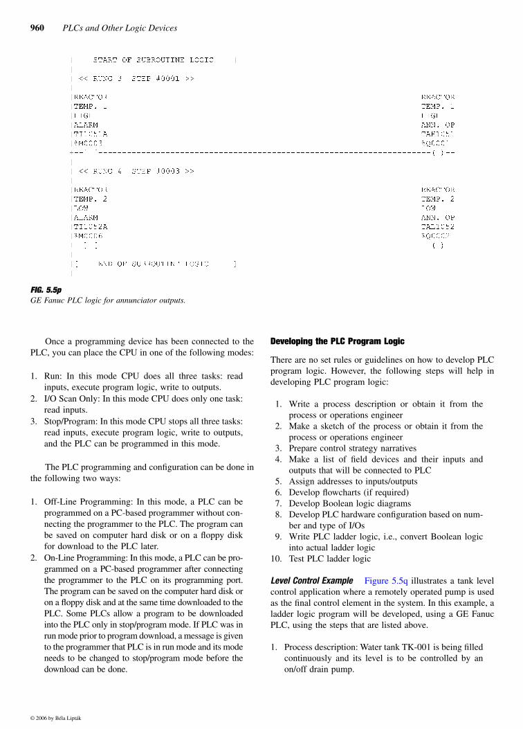
deadband.Figure 5.5p shows a typical PLC logic for annunciator
outputs.
Typical Allen-Bradley PLCs
A program in Allen-Bradley PLC-5 is organized in a filestructure. First, you create a project with an appropriatename. In the project, there are program files as explainedbelow:
In a typical project, there are different types of data files,such as:
Data files O0 (output) and I1 (input) are physical I/Ostatus files.
Data file S2 (status) is a general status file.Data files B3 (binary), T4 (timers), C5 (counters), R6
(control word), N7 (integer), F8 (floating) arereserved for the main program file. Other data filescan be designated for subroutines as needed.
Addressing is done in the following format:
XY:WW:ZZ
whereX is the file identifier such as I for input, O for output, S
for status, B for binary, T for timers, C for counters, R for real, N for integer, and F for floating point
Y is the file number (in decimal) such as 0 for output, 1 for input
WW is the word number (in decimal) in file such as 00 for word #1
ZZ is the bit number (in octal) in a word such as 00 for bit #1
A program in Allen-Bradley’s ControlLogix PLC is orga-nized by tasks. First, you should identify a project with anappropriate name and controller type. In the project, thereare a variety of tasks, programs, and routines. For example,the controller contains controller tags, controller fault han-dler, and power-up handler. The controller tags are globaltags that can be used by all programs.
Controller supports 31 separate tasks. Each task can con-tain multiple programs, status information, and configurationinformation.
There is always a main task, which is created when youcreate the project and is by default a continuous task. Other(up to 30) tasks are user-defined and are periodic tasks. There
TABLE 5.5kGE Fanuc PLC Memory Identifiers and Address Format
Type of MemoryMemoryIdentifier Address Format
DIGITAL INPUT %I %I0001
DIGITAL OUTPUT %Q %Q0001
ANALOG INPUT %AI %AI001
ANALOG OUTPUT %AQ %AQ001
INTERNAL COIL %M %M0001
REGISTER %R %R0001
SYSTEM %S %S0001
TEMPORARY %T %T0001
GLOBAL %G %G0001
TABLE 5.5lGE Fanuc PLC Variable Declaration Table
Reference Nickname Description
%I0001 PSL001 TANK TK-1 LOW PRESSURE
%Q0001 SV001 TANK TK-1 AIR SOLENOID
%AI001 PT001 TANK TK-1 PRESSURE TX
%AQ001 PCV001 TANK TK-1 PRESSURE CONTROL VALVE
%M0001 TK1PLTD TANK TK-1 LOW PRESSURE FOR10 SEC TIMER DONE
%R0001 TK1PLTMR TANK TK-1 LOW PRESSURE 10 SEC TIMER
File # Name Description
0 System PLC operating system, unavailable to programmers
1 Undefined PLC operating system, unavailable to programmers
2 Main program Main program code and subroutine calls
3–999 Subroutines Subroutine code, called by main program
© 2006 by Béla Lipták

5.5 PLC Programming 957
can be up to 32 programs in a task. The program containsprogram tags and routines. Program tags are local tags thatcan be used by routines within an individual program. Thereis a main routine, which gets executed first in each program.The main routine is used to make calls to other routines.
A program can be scheduled or unscheduled for exe-cution. Scheduled programs are executed and unscheduled
programs are not executed. Data types for tags can be user-defined or predefined. There are module-defined data types,as well. There are no physical or internal addresses assignedto tags. Tags are referenced in the programs by their names.Tags have various parameters depending on their data type.I/O configuration is used to configure the physical I/Omodules.
FIG. 5.5mGE Fanuc PLC rack and CPU configuration.
© 2006 by Béla Lipták

958 PLCs and Other Logic Devices
Typical Modicon PLC 984
A program in Modicon PLC is organized in networks. First,you create a program file. In the program file, there aresegments that are made up of logic networks. In PLC 984,there are 1–32 segments, and you can write logic networksin each of these segments. Network numbers start from 1 andare continuous for the program. Addressing is done in thefollowing format for data tables:
XYYYY
where X is data type identifier such as 0 for discrete o/p orcoil (used to drive real outputs through output module or toset internal coils), 1 for discrete input (used to drive contactsin the logic program, controlled by input module), 3 for inputregister (holds numeric input from external source like analog
or high-speed counter input module), and 4 for output holdingregisters (used to store numeric data for internal use or analogoutput module).
YYYY is reference number in decimal such as 1, 2, etc.,with upper limit as configured.
Total memory for all data types should not exceed pro-cessor user memory.
Access and Programming Modes
The following are a few ways of connecting a programmingdevice with a PLC:
1. Serial connection 2. Ethernet3. Data Highway Plus (DH+)
FIG. 5.5nGE Fanuc PLC logic for analog inputs.
© 2006 by Béla Lipták

5.5 PLC Programming 959
FIG. 5.5oGE Fanuc PLC logic for alarm with deadband.
© 2006 by Béla Lipták
960 PLCs and Other Logic Devices
Once a programming device has been connected to thePLC, you can place the CPU in one of the following modes:
1. Run: In this mode CPU does all three tasks: readinputs, execute program logic, write to outputs.
2. I/O Scan Only: In this mode CPU does only one task:read inputs.
3. Stop/Program: In this mode CPU stops all three tasks:read inputs, execute program logic, write to outputs,and the PLC can be programmed in this mode.
The PLC programming and configuration can be done inthe following two ways:
1. Off-Line Programming: In this mode, a PLC can beprogrammed on a PC-based programmer without con-necting the programmer to the PLC. The program canbe saved on computer hard disk or on a floppy diskfor download to the PLC later.
2. On-Line Programming: In this mode, a PLC can be pro-grammed on a PC-based programmer after connectingthe programmer to the PLC on its programming port.The program can be saved on the computer hard disk oron a floppy disk and at the same time downloaded to thePLC. Some PLCs allow a program to be downloadedinto the PLC only in stop/program mode. If PLC was inrun mode prior to program download, a message is givento the programmer that PLC is in run mode and its modeneeds to be changed to stop/program mode before thedownload can be done.
Developing the PLC Program Logic
There are no set rules or guidelines on how to develop PLCprogram logic. However, the following steps will help indeveloping PLC program logic:
1. Write a process description or obtain it from theprocess or operations engineer
2. Make a sketch of the process or obtain it from theprocess or operations engineer
3. Prepare control strategy narratives4. Make a list of field devices and their inputs and
outputs that will be connected to PLC5. Assign addresses to inputs/outputs6. Develop flowcharts (if required)7. Develop Boolean logic diagrams8. Develop PLC hardware configuration based on num-
ber and type of I/Os9. Write PLC ladder logic, i.e., convert Boolean logic
into actual ladder logic10. Test PLC ladder logic
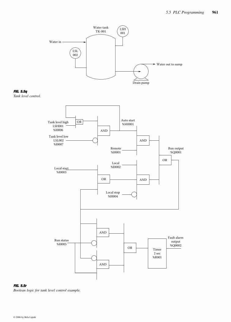
Level Control Example Figure 5.5q illustrates a tank levelcontrol application where a remotely operated pump is usedas the final control element in the system. In this example, aladder logic program will be developed, using a GE FanucPLC, using the steps that are listed above.
1. Process description: Water tank TK-001 is being filledcontinuously and its level is to be controlled by anon/off drain pump.
FIG. 5.5pGE Fanuc PLC logic for annunciator outputs.
© 2006 by Béla Lipták
5.5 PLC Programming 961
FIG. 5.5qTank level control.
FIG. 5.5rBoolean logic for tank level control example.
Water tankTK-001
Drain pump
Water in
Water out to sump
LSH001
LSL002
Tank level highLSH001%I0006
Auto start%M0001
OR
AND
Tank level lowLSL002%I0007
OR
AND
Remote%I0001
AND
Local%I0002
Local stop%I0004
Local start%I0003
OR
Run output%Q0001
AND
Run status%I0005
AND
OR Timer2 sec
%R001
Fault alarmoutput
%Q0002
© 2006 by Béla Lipták

962 PLCs and Other Logic Devices
2. Make a sketch of the process: Make a sketch as shownin Figure 5.5q.
3. Prepare control strategy narrative for this pump, whichhas two modes of operation:• Remote mode: In this mode, its operation is con-
trolled automatically by the level in the tank. Whenthe level rises to its high limit (say 90%), the waterpump should start to drain the water to the sump.Pump will continue to drain water until the leveldrops to its low limit (say 10%) in TK-001.
• Local mode: In this mode, the pump operation iscontrolled by the operator out in the field, and theautomatic level control logic is bypassed.
4. Make a list of field devices (sensors and so on) and theirinputs and outputs that will be connected to the PLC.
5. Assign addresses to inputs/outputs.
6. Develop Boolean logic diagram as shown in Figure 5.5r.7. Develop PLC hardware configuration as shown in Fig-
ure 5.5m without the analog modules in slots 4 and 5.8. Write PLC ladder logic, i.e., convert Boolean logic
developed in previous step into ladder logic as shownin Figure 5.5s.
9. Download program in PLC and test the program asexplained below.
TESTING AND SIMULATION
Once the logic is entered in the PLC, the next step is to debugthe program to make sure that the logic works the way it issupposed to and to correct any errors made while developingand writing the PLC program.
Input modules with switches to simulate the input signalsare used. Such a simulation module is installed to simulatethe digital inputs to the PLC. The PLC is placed in the runmode, and its inputs are simulated by operating the corre-sponding switches. The logic outputs are checked to see ifthe program properly carries out the required logic. The statusof the internal coils is determined by using the PLC datatable.
Instead of using simulation modules, it is also possibleto use the FORCE I/O function in the PLC to enable ordisable inputs in order to simulate field inputs. FORCE ONcan be used to turn input on and FORCE OFF can be usedto turn input off. Once the inputs are forced on or off youwould proceed to check if the program has turned the various
Field Device Input Output Remarks
Local/remote switch 02 — For pump operation control
Local start pushbutton 01 — To start pump in localmode
Local stop pushbutton 01 — To stop pump in local mode
Water pump 01 01 Input = Run status,Output = Run command
Motor fault alarm — 01 For annunciation
LSH001 01 — High-level switch
LSL002 01 — Low-level switch
Field Device Input Output PLC Address
Local/remote switch 02 — %I0001 (Remote),%10002 (Local)
Local start pushbutton 01 — %I0003
Local stop pushbutton 01 — %I0004
Water pump 01 01 %I0005 (Run status), %Q0001 (Run command)
Motor fault alarm — 01 %Q0002
LSH001 01 — %I0006
LSL002 01 — %I0007
FIG. 5.5sPLC logic for tank level control example.
Run output%Q0001
Remote%I0001
Auto start%M0001
Local%I0002
Local start%I0003
Local stop%I0004
Run output%Q0001
Fault alarm output%Q0002
Timer2 sec
%R001
Run output%Q0001
Run output%Q0001
Run status%I0005
Run status%I0005
Auto start%M0001
Water tank TK-001Level highLSH001%I0006
Water tank TK-001Level lowLSL002%I0007
Auto start%M0001
© 2006 by Béla Lipták

5.5 PLC Programming 963
FIG. 5.5tPLC system with ASCII basic module for weigh scale interface.
FIG. 5.5uGE Fanuc PLC rack and ASCII basic module configuration.
Powersupplymodule
CPUASCIIbasic
module
Digitaloutputmodule
Analoginput
module
110 VACor
220 VAC
Weigh scalewith RS-232 ASCII
communication
Analogoutputmodule
Programming device
Programming port #1(RS-232)
Data port #2(RS-232)
5-Slot rack
© 2006 by Béla Lipták

964 PLCs and Other Logic Devices
outputs on or off per the logic. Again, the status of the internalcoils is determined by using the PLC data table.
In case of large PLC systems with a lot of I/Os, you shoulduse a graphical process simulator package, which can be devel-oped by using MMI packages. As was discussed in Section4.13 in Chapter 4, processes can be displayed graphically onthe screen and respond to the PLC signals in the same manneras the actual process would. Equipment can be operated fromthe screen, and their status can be seen on the screen. Naturally,interface cards are needed to connect PLC to computer runningsimulator programs.
ADVANCES IN PROGRAMMING
Until recently, most of the PLC programming softwares avail-able in the market were DOS-based for ladder logic program-ming. Recently, as Windows-based laptop computers are
becoming inexpensive and popular, PLC manufacturers arecoming out with Windows-based programming software.
The advantages of Windows-based programming soft-ware include ease of programming, the ability to use multiplewindows to do both the programming and the troubleshoot-ing, and an improvement in the on-line help available forprogramming.
Another significant advancement is the PLC’s ability tocommunicate with intelligent devices using interface cardsthat are programmable in the Basic language. This interfacemodule is called ASCII Basic module and is physicallyinstalled in the PLC rack like any other module; it is pro-grammed using a serial port on the module.
One such system used for weigh scale interfacing isshown in Figure 5.5t. In this system, ASCII Basic module isprogrammed in Basic language to read the measured weightfrom the weigh scale using RS-232 serial communication.
Figure 5.5u shows the PLC configuration, andFigure 5.5v shows the Basic code for an ASCII module. This
This basic module code reads the weigh scale data string from port #2 and stores the crate weight and tare weight values inPLC memory. Weigh scale data string format is <STX>xxxx yyyy<CR> where xxxx is crate weight and yyyy is tare weight.Programming PC is to be connected at port #1 for programming/debugging.
10 REM DATALINK TO WEIGH SCALE -- remark
20 STRING 1026,40 -- allocates string memory
30 SETCOM 9600 -- sets communication parameters for programming (port #1)
40 SETCOM #9600,E,7,1,N,0 -- sets communication parameters for weigh scale (port #2)
50 SETINPUT 1,1,13,17,10,10 -- input statement configuration
60 INPUT # $(1) -- inputs data from weigh scale (port #2)
70 PRINT “WEIGH SCALE RESPONSE IS : “, $(1) -- prints weigh scale data string on port #1
80 $(2) = LEFT$ ($(1),1) -- assigns 1st character of data string to $(2)
90 $(3) = MID$ ($(1),2,4) -- assigns crate weight data string to $(3)
100 $(4) = MID$ ($(1)7,4) -- assigns tare weight data string to $(4)
110 IF $(2) = CHR$ (02) THEN GOTO 160 ELSE GOTO 120 -- if 1st character is <STX> then valid data
120 OUT(2,0) = 1 -- sets bad value flag in PLC memory (bit 1 of AI011)
130 WEIGHT = 0 -- sets crate weight to 0
140 TWEIGHT = 0 -- sets tare weight to 0
150 GOTO 190
160 WEIGHT = VAL ($(3)) -- sets crate weight to value read from weigh scale
170 TWEIGHT = VAL ($(4)) -- sets tare weight to value read from weigh scale
180 OUT(2,0) = 0 -- resets bad value flag in PLC memory (bit 1 of AI011)
190 PRINT “WEIGHT IS : “, WEIGHT -- prints crate weight on port #1
200 PRINT “TARE WEIGHT IS : “, TWEIGHT -- prints tare weight on port #1
210 OUT (0) = WEIGHT -- stores crate weight in PLC memory (AI009)
220 OUT (1) = TWEIGHT -- stores tare weight in PLC memory (AI010)
230 GOTO 50
240 RETURN
FIG. 5.6vBasic program for ASCII basic module.
© 2006 by Béla Lipták
5.5 PLC Programming 965
type of application can be used to connect the PLC to anyintelligent device that supports ASCII serial communication.Some typical applications include RF tag readers and labelingstations.
As PC costs keep dropping, personal computers are usedmore and more in place of conventional PLCs. PCs can solveladder logic, scan I/Os, and communicate with other networkdevices, if the appropriate software is loaded into them. How-ever, there are safety considerations to be resolved if the PCis shared among several applications. Yet there already are anumber of small-scale PC-based control systems in use today,in areas such as data acquisition, process monitoring, andbatch control.
An alternative to relay ladder logic (RLL) is state logic.It is a language that forces the user to build the program withfinite states. It uses a natural language, known as EnglishControl Language Programming Software (ECLiPS), whichallows the programmers to write their control commands intheir own words. State logic was created to reduce the pro-gram development and modification time.
Reference
1. Lipták, B. G., Instrument Engineers’ Handbook, 4th edition, ProcessControl, Section 5.4 and other sections in Chapter 5, Boca Raton, FL:CRC Press, 2005.
Bibliography
Allen-Bradley, Logix5000 Controllers Programming Documentation Refer-ence Guide.
Allen-Bradley, PLC-5 Programming Software, Instruction Set Reference,Release 4.4.
Allen-Bradley, PLC-5 Programming Software, Software Configuration andMaintenance.
Carrow, R. A., Soft Logic: A Guide to Using a PC as a Programmable LogicController, New York: McGraw-Hill, 1997.
Cox, R. D., Technician’s Guide to Programmable Controllers, New York:Delmar, 1995.
GE Fanuc, Logic Master 90-70 Programming Software User’s Manual,August 1992.
GE Fanuc, Series 90-70 Programmable Controller Reference Manual, July1992.
GE Fanuc, MegaBasic Language Reference and Programmer’s Guide,September 1994.
Horner Electric, ASCII Basic Module User’s Guide, May 1995.IEC 61131-3, “Programming Languages,” IEC, 1993.Lewis, R. W., Programming Industrial Control Systems using IEC 61131-
3, U.K.: British Institute of Electrical Engineers (IEE), 1998. Modicon, Ladder Logic Block Library User Guide, 1994.Modicon, 984 Controller Loadable Function Block Programming Guide,
February 1992.Parr, E. A., Programmable Controllers, Butterworth-Heinemann, 1999. Petruzelka, F. D., Programmable Logic Controllers, New York: Glencoe, 1998.Simpson, C., Programmable Logic Controllers, Englewood Cliffs, NJ: Pren-
tice Hall, 1994.Webb, J. W. and Reis, R. A., Programmable Logic Controllers Principles
and Applications, Englewood Cliffs, NJ: Prentice Hall, 1999.
© 2006 by Béla Lipták