550 autogo - ezmobilitybattery ultralight 550... · 2013-11-04 · autogo 550 vehicle owner’s...
TRANSCRIPT

A Division of Electric Mobility Corp.1 Mobility Plaza • Sewell, NJ 08080
AutoGo™ 550Owners ManualPatents Pending
19285600 Rev.03.FC 9/15/04, 4:59 PM1

AutoGo 550 Vehicle Owner’s Manual
EMC Part: 19285600 • Rev. 03 • 09/15/04i
Please read this entire manual before operating the vehicle. Failure to do
so may result in damage to the vehicle or serious injury.
Electric Mobility wishes to thank you for choosing the revolutionary AutoGo™ 550 vehicle for fun and convenience. As theWorld’s leader in the design and production of personal mobility vehicles, we take great pride in our ability to improve thequality of life for people desiring more mobility. Your AutoGo 550 has been thoroughly tested and will give you years of goodservice and pleasure, providing you follow the instructions and precautions in this manual. Please review this manual in itsentirety prior to first using your equipment and direct any questions you might have to your authorized provider or write/call:
Electric Mobility Corp.
USA Canada United Kingdom1 Mobility Plaza 1535 Meyerside Drive, Unit #13-14 Canal WaySewell, NJ 08080 Mississauga, ON L5T 1M9 Ilminster, Somerset, England TA19 9DL1-(800) 257-7955 (905) 565-1988 01460-258100
International: 1-(856) 468-1000
Please keep this manual handy for easy reference.Please record your vehicle information for future reference:
AutoGo 550
Serial Number:
Date of Purchase:
19285600 Rev.03.FM 10/12/04, 1:11 PM1

AutoGo 550 Vehicle Owner’s Manual
EMC Part: 19285600 • Rev. 03 • 09/15/04ii
CONTENTSTitle Page
Safety Information .................................................................................. 1
Getting to Know Your AutoGo 550 .................................................. 5Illustration 1 — AutoGo 550 Components ............................................... 6Initial Set-up .............................................................................................. 7
Unfolding ............................................................................................... 7Charging Batteries ............................................................................... 8
Illustration 2 — Battery Charging .................................................... 9Installing the Battery Pack ................................................................ 11
Illustration 3 — Battery Pack Installation ...................................... 11Adjusting Tiller Position .................................................................... 12
Illustration 4 — Tiller Adjustment Lever ......................................... 12Installing & Setting the Dashboard Clock ..................................... 13
Controls .................................................................................................. 14Illustration 5 — Controls ..................................................................... 14
Operating the AutoGo 550 ............................................................... 19Daily Use ................................................................................................. 19
Transferring On or Off the Vehicle ................................................. 20Driving ................................................................................................. 20
Speed Settings ............................................................................... 22Inclines ............................................................................................ 22Cornering & Turning ..................................................................... 22
Title Page
Curbs and Small Obstacles ........................................................... 23Freewheel Operation ..................................................................... 23
Automatic Folding and Unfolding .......................................................... 24Folding Instructions ............................................................................. 24
Illustration 6 — Folding Seatback Down ......................................... 24Illustration 7 — Dash Release Lever ............................................... 25Illustration 8 — Foot Release & Frame Lock .................................. 25Illustration 9 — Folding Operation ................................................... 27
Unfolding Information ........................................................................ 28Flat Folding and Unfolding .................................................................. 29
Illustration 10 — Flat Fold ................................................................ 29Illustration 11 — Unfolding Flat Folded Vehicle ............................... 30
Disassembly & Re-Assembly .................................................................. 31Taking the AutoGo 550 Apart ........................................................... 31
Illustration 12 — Seat Removal ....................................................... 31Illustration 13 — Battery Pack Removal ......................................... 32Illustration 14 — Flattening Seat Frame ......................................... 33Illustration 15 — Unplugging Drivetrain .......................................... 33
Re-assembling the AutoGo 550 ........................................................ 34Illustration 16 — Drivetrain Connection .......................................... 34
Transporting the AutoGo 550 ............................................................... 36
19285600 Rev.03.FM 10/12/04, 1:11 PM2

AutoGo 550 Vehicle Owner’s Manual
EMC Part: 19285600 • Rev. 03 • 09/15/04iii
Title Page
Maintenance .............................................................................................. 38Preventative Maintenance ....................................................................... 38
Frame Inspection ................................................................................. 38Headlight ............................................................................................... 39Lubrication ............................................................................................ 39Tires ....................................................................................................... 40Electrical Connections ....................................................................... 40Hardware Inspection .......................................................................... 40Cleaning Instructions .......................................................................... 40Polishing ................................................................................................ 41Cable Adjustment ................................................................................ 41
Title Page
Illustration 17 — Cable Turnbuckle Adjustment .............................. 42Drivetrain ............................................................................................. 43Seat Frame Cams ................................................................................ 43Replacing Clock Battery ..................................................................... 44
Illustration 18 — Replacing Clock Battery ...................................... 44Troubleshooting Guide ........................................................................... 46Controller Fault Codes .......................................................................... 48Parts Ordering Procedures .................................................................... 49Accessories ............................................................................................... 50
Specifications ............................................................................................. 51
Warranty ..................................................................................................... 52
19285600 Rev.03.FM 10/12/04, 1:11 PM3

AutoGo 550 Vehicle Owner’s Manual
EMC Part: 19285600 • Rev. 03 • 09/15/04iv
ILLUSTRATIONSNumber Title Page
1 AutoGo 550 Components ................................................ 62 Battery Charging ................................................................. 93 Battery Pack Installation ................................................... 114 Tiller Adjustment Lever ................................................... 125 Controls .............................................................................. 146 Folding Seatback Down .................................................... 247 Dash Release Lever ........................................................... 258 Foot Release & Frame Lock ............................................ 259 Folding Operation ............................................................. 27
Number Title Page
10 Flat Fold .............................................................................. 2911 Unfolding Flat Folded Vehicle ........................................... 3012 Seat Removal ..................................................................... 3113 Battery Pack Removal ...................................................... 3214 Flattening Seat Frame ....................................................... 3315 Unplugging Drivetrain ....................................................... 3316 Drivetrain Connection ..................................................... 3417 Cable Turnbuckle Adjustment ......................................... 4218 Replacing Clock Battery .................................................. 44
© 2003 Electric Mobilty Corp.AutoGo™ 550 is a trademark of Electric Mobilty Corp.Patents Pending
No liability is assumed with respect to the use of any information contained in this publication. While every precaution has been taken in the preparation of this publication, ElectricMobilty Corp., assumes no responsibility for errors or omissions nor is any liability assumed for damages resulting from the use of information contained in this publication. Thispublication, as well as operational details described herein, are subject to change without notice.
19285600 Rev.03.FM 10/12/04, 1:11 PM4

AutoGo 550 Vehicle Owner’s Manual
EMC Part: 19285600 • Rev. 03 • 09/15/041
Safety Information
Read and understand these Warnings and the entire manual before using your AutoGo 550. Failure to follow theseinstructions may result in damage to the vehicle or serious injury.
IMPORTANT!
1. DO NOT exceed the specifications of this unit, modifythis unit in anyway, or use the unit for a purpose otherthan as intended.
2. DO NOT operate this unit if your health ormedications you are taking cause you to feel dizzy, affectyour vision, or in any way impact your thought process,coordination, or ability to safely operate the unit. Checkwith your physician should you experience any of thesesymptoms.
3. DO NOT operate this unit after consuming anyalcoholic beverages.
4. DO NOT transfer “on” or “off” the unit until it isturned “OFF”, completely stopped, and when it is on astable and level surface.
5. DO NOT attempt to ride over curbs or otherobstruction higher than 1 inch.
6. DO NOT stop when going up an incline. If you mustdo so, always lean forward to shift the center of gravityand prevent the unit from tipping.
7. DO NOT climb inclines that pose a concern forstability.
19285600 Rev.03.OM 9/15/04, 5:34 PM1

AutoGo 550 Vehicle Owner’s Manual
EMC Part: 19285600 • Rev. 03 • 09/15/042
8. DO NOT drive across an incline or attempt to turnwhile on an incline.
9. DO NOT back down an incline or allow the unit to bebacked down an incline.
10. DO NOT turn off the power while the unit is moving.
11. ALWAYS remember vehicle capacity is limited to oneperson only. This unit is not approved for towing or forweights in excess of the published maximum.
12. ALWAYS drive straight up and down inclines.
13. ALWAYS turn the power off when the unit is not inuse. This will not only extend the life of the charge inthe battery but will keep the unit from beingaccidentally moved.
14. ALWAYS use a grounded receptacle. Use of a non-grounded receptacle could result in an electrical shock.
15. ALWAYS reduce speed when making a turn.
16. ALWAYS keep arms and legs within the confines ofthe unit.
17. USE EXTRA CAUTION when climbing inclines(ramps, hills, driveways, etc.).
18. USE CAUTION when braking on an incline or wet orslippery surfaces as the unit may take longer to come toa complete stop.
19. USE CAUTION when operating the unit in badweather or driving through water as moisture couldaffect the control system or other parts of the uniteither temporarily or permanently.
20. OPERATOR must remain seated when the unit ismoving.
21. NEVER hose off your vehicle.
22. NEVER use your unit in a shower or steam room.
23. NEVER charge batteries that may be frozen.
19285600 Rev.03.OM 9/15/04, 5:34 PM2

AutoGo 550 Vehicle Owner’s Manual
EMC Part: 19285600 • Rev. 03 • 09/15/043
Important Information Regarding Electromagnetic Interference (EMI)It is very important that you read this information regarding the possible effects of electromagnetic interference (EMI) onyour vehicle.
Electromagnetic interference (EMI) refers to the effects that outside sources of electromagnetic energy (radio andtelevision broadcasts, CB radios, garage door openers, etc.) might have on the control systems of your vehicle. Theinterference from these sources could cause the vehicle to release its brakes, move by itself, or to move in an unintendeddirection. EMI could also result in permanent damage to the control system.
The sources of electromagnetic energy can be broadly classified into three types:
• Hand held short-range portable transceivers — These are transmitter/receivers with the antenna mounteddirectly on the unit. Examples include: citizen band (CB) radios, “walkie-talkies”, security, fire and police transceivers,and devices that transmit signals even when not in use.
• Medium range mobile transceivers — These usually have the antenna mounted outside of a vehicle or building.Examples include police, fire, and ambulance and taxi transceivers.
• Long range transmitters and receivers — These usually have the antenna mounted on a tower. Examplesinclude commercial radio and television broadcasts and amateur (HAM) radios.
19285600 Rev.03.OM 9/15/04, 5:34 PM3

AutoGo 550 Vehicle Owner’s Manual
EMC Part: 19285600 • Rev. 03 • 09/15/044
Other types of hand-held devices like cellular telephones, laptop computers, AM/FM radios, and small appliances like hairdryers or electric shavers may also generate electromagnetic energy, but it is such a small amount that, as far as we know,no EMI problems should occur with these devices.
The intensity of interference from electromagnetic energy is measured in volts per meter (v/m), which refers to thestrength of the electrical source (voltage) as it relates to the distance away from the object being considered (in meters).Resistance of a vehicle to a certain EMI intensity is commonly called its “immunity level.” A level of 20 volts/meter is agenerally achievable and useful immunity level against interference from radio wave sources (the higher the immunity level,the greater the protection).
Your vehicle has been tested and found to meet the required immunity level for Electromagnetic Interference (20 v/m).
Report all incidents of unintended movement or unexpected brake releases to Electric Mobility’s customer servicedepartment.
WARNING!
Even with an immunity level of 20 volt/meter, certain precautions must be
followed to ensure that your vehicle will not be affected by outside
electromagnetic sources.
19285600 Rev.03.OM 9/15/04, 5:34 PM4

AutoGo 550 Vehicle Owner’s Manual
EMC Part: 19285600 • Rev. 03 • 09/15/045
Getting to Know Your AutoGo 550
Dash & Controls — The AutoGo 550 is operated from the controls located on the dashboard and the Forward/Reverselever which controls the power folding/unfolding feature. Detailed descriptions of these controls are presented in aseparate part of this section (see “Controls” on page 14).
Serial Number — Each AutoGo 550 is identified by a unique, 8-character Serial Number located on a label on the insideof the tiller, behind the Battery Pack. When you first get your vehicle, remove the Battery Pack and write down thevehicle’s Serial Number in the front of this manual (see page i) for future reference.
Tiller & Battery Pack — The front, steerable tiller directs the AutoGo 550 into your desired direction of movement. Aremovable Battery Pack is mounted on the front of the Tiller. This Battery Pack also contains the integral Battery Charger.A separate Charger Power Cord is used to recharge the batteries from any 3-prong wall electrical outlet.
Seat — A removable, adjustable, padded seat provides riding comfort when using your AutoGo 550. Folding backrest andarmrests allow for compact storage.
Folding Chassis — The hinged, articulated chassis of the AutoGo 550 allows it to automatically fold and unfold for useand storage.
Drivetrain — A removable Drivetrain mounted at the rear of the chassis provides power to drive the AutoGo 550vehicle and to power fold it. A self-contained parking brake has a manual release which allows the vehicle to be manuallypushed without operating the motor.
19285600 Rev.03.OM 9/15/04, 5:34 PM5

AutoGo 550 Vehicle Owner’s Manual
EMC Part: 19285600 • Rev. 03 • 09/15/046
Illustration 1 — AutoGo 550 Components
DASH
&
CONTROLS
TILLER
&
BATTERY PACK
SEAT
FOLDING
CHASSIS
DRIVETRAIN
19285600/1
SERIAL
NUMBER
19285600 Rev.03.OM 9/15/04, 5:34 PM6

AutoGo 550 Vehicle Owner’s Manual
EMC Part: 19285600 • Rev. 03 • 09/15/047
Initial Set-up
After receiving and unpacking your AutoGo 550 use the following to initially set-up the vehicle. Set-up consists ofunfolding it from the flat-fold configuration, installing the Battery Pack, installing/setting the dashboard clock, and chargingthe batteries.
Unfolding
The AutoGo 550 is initially shipped in the flat fold configuration and must be unfolded for use. Unfold the AutoGo 550according to the following:
• Raise tiller and dash to upright position
• Raise seat frame and lock into position using the Seat Frame Cams
• Install seat onto frame
• Raise seat backrest to driving position
19285600 Rev.03.OM 9/15/04, 5:34 PM7
AutoGo 550 Vehicle Owner’s Manual
EMC Part: 19285600 • Rev. 03 • 09/15/048
Charging Batteries
The AutoGo 550 is equipped with two maintenance-free, airline approved, sealed 12V/12A batteries with an integralautomatic battery charger mounted in a detachable Battery Pack installed onto the front of the tiller. Because yourbatteries may only have a partial charge when you first receive your vehicle, you may not experience full riding time untilyou have fully charged them. Charging your batteries as specified in the following instructions will ensure maximum life,power, and range.
It is recommended to charge your batteries:
• Upon initial receipt of your AutoGo 550
• For 6-8 hours (overnight) after extended use during the day
• Whenever the fuel gauge indicator goes into the red area (see page 17)
• The battery’s life expectancy may be shortened if batteries are left fully discharged for more than a day.
Battery Pack and power cord connections are shown in Illustration 2.
19285600 Rev.03.OM 9/15/04, 5:34 PM8

AutoGo 550 Vehicle Owner’s Manual
EMC Part: 19285600 • Rev. 03 • 09/15/049
Illustration 2 — Battery Charging
CHARGER
CORD
CONNECTION
CIRCUIT
BREAKER
"CHARGING"
LED
INDICATOR
19285600/2
(REAR VIEW OF TILLER)
19285600 Rev.03.OM 9/15/04, 5:34 PM9
AutoGo 550 Vehicle Owner’s Manual
EMC Part: 19285600 • Rev. 03 • 09/15/0410
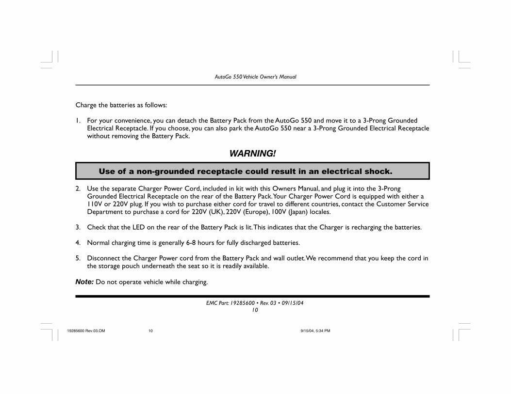
Charge the batteries as follows:
1. For your convenience, you can detach the Battery Pack from the AutoGo 550 and move it to a 3-Prong GroundedElectrical Receptacle. If you choose, you can also park the AutoGo 550 near a 3-Prong Grounded Electrical Receptaclewithout removing the Battery Pack.
WARNING!
Use of a non-grounded receptacle could result in an electrical shock.
2. Use the separate Charger Power Cord, included in kit with this Owners Manual, and plug it into the 3-ProngGrounded Electrical Receptacle on the rear of the Battery Pack. Your Charger Power Cord is equipped with either a110V or 220V plug. If you wish to purchase either cord for travel to different countries, contact the Customer ServiceDepartment to purchase a cord for 220V (UK), 220V (Europe), 100V (Japan) locales.
3. Check that the LED on the rear of the Battery Pack is lit. This indicates that the Charger is recharging the batteries.
4. Normal charging time is generally 6-8 hours for fully discharged batteries.
5. Disconnect the Charger Power cord from the Battery Pack and wall outlet. We recommend that you keep the cord inthe storage pouch underneath the seat so it is readily available.
Note: Do not operate vehicle while charging.
19285600 Rev.03.OM 9/15/04, 5:34 PM10

AutoGo 550 Vehicle Owner’s Manual
EMC Part: 19285600 • Rev. 03 • 09/15/0411
Installing the Battery Pack
After the batteries have been fully charged, you’ll be ready to install the Battery Pack into the Tiller. Install the batterypack as follows (see Illustration 3).
TIP BOTTOM
INTO TILLER
PUSH TOP OF BATTERY PACK
FIRMLY IN PLACE
19285600/3
SLOT ENGAGES
BAR ON TILLER
LOCK BATTERY
PACK HANDLE
CORRECT INCORRECT
1. Lift the Battery Pack by the handle and insert thebottom of the Battery Pack into the bottom of the Tiller.Line up the slot under the pack with the bar on lowershelf of tiller.
2. Firmly push the top front of the Battery Pack into thetiller until it “snaps” in place. Ensure that the (5) pintiller connector mates tightly with the connector of theBattery Pack.
3. Make sure the handle on the battery pack is fullyreturned to its seated position to lock the Battery Packin place.
Illustration 3 — Battery Pack Installation
19285600 Rev.03.OM 9/15/04, 5:34 PM11

AutoGo 550 Vehicle Owner’s Manual
EMC Part: 19285600 • Rev. 03 • 09/15/0412
Adjusting Tiller Position
For your riding comfort, the AutoGo 550 tiller can be usedin two positions.
To adjust tiller position:
• Lift Tiller Position Adjustment Knob to release tillerlock
• Adjust tiller to preferred position
• Release knob to lock in place
This adjustment lever is shown in Illustration 4
Illustration 4 — Tiller Adjustment Lever
TILLER
POSITION
ADJUSTMENT
KNOB
19285600/4
19285600 Rev.03.OM 9/15/04, 5:35 PM12

AutoGo 550 Vehicle Owner’s Manual
EMC Part: 19285600 • Rev. 03 • 09/15/0413
Installing & Setting the Dashboard Clock
Your AutoGo 550 comes with a removable, battery-powered, quartz clock that mounts directly in the dash. This clock ispacked separately to allow you to set it to your local time before installing in the dash.
Setting the Clock — Locate the bag containing items packed separately with the vehicle. Unwrap the clock from itsprotective packing. If clock includes a small, plastic collar around stem, remove collar and push stem “in” to start clock.
Set clock to your local time by pulling stem out and turning to adjust hour/minute hands. Push stem in to start clock.
Installing the Clock — When you have set the clock to your correct, local time, you can install it in the dash of yourvehicle. Install the clock into the location adjacent to the Speed Control. The rubber gasket is sufficient to secure theclock in place. Make sure the “12” faces “up.”
19285600 Rev.03.OM 9/15/04, 5:35 PM13

AutoGo 550 Vehicle Owner’s Manual
EMC Part: 19285600 • Rev. 03 • 09/15/0414
Controls
The AutoGo 550 includes the following controls (Illustration 5) used to operate the vehicle. Individual descriptions ofeach control are presented in pages 15-18.
12
39
6
CLOCK
DIAL-A-SPEED
BATTERY
GAUGE
HORN
LIGHT
SWITCH
KEYSWITCH
19285600/5
Illustration 5 — Controls
19285600 Rev.03.OM 9/15/04, 5:35 PM14

AutoGo 550 Vehicle Owner’s Manual
EMC Part: 19285600 • Rev. 03 • 09/15/0415
Keyswitch
To turn power on, turn the key to the “On” position(indicated by a solid black circle). To turn power off, turnkey to “Off” position (indicated by an open circle). TheBattery Gauge (Fuel Gauge) should be lit when the key is inthe “On” position.
Use of a key to turn the AutoGo 550 on and off alsoprotects against unauthorized use of your AutoGo 550.
Battery Power Save Feature
The AutoGo 550 is equipped with a power save feature and,will shut down automatically in order to conserve batterypower when not operated for 10 minutes or more. Thevehicle can be turned on again by cycling the ON/OFFkeyswitch from ON to OFF and then ON again.
"OFF"
POSITION
"ON"
POSITION
19285600 Rev.03.OM 9/15/04, 5:35 PM15
AutoGo 550 Vehicle Owner’s Manual
EMC Part: 19285600 • Rev. 03 • 09/15/0416
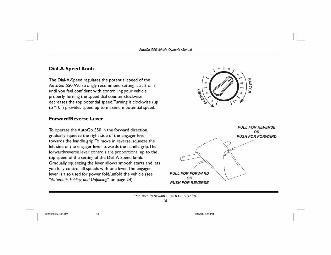
Dial-A-Speed Knob
The Dial-A-Speed regulates the potential speed of theAutoGo 550. We strongly recommend setting it at 2 or 3until you feel confident with controlling your vehicleproperly. Turning the speed dial counter-clockwisedecreases the top potential speed. Turning it clockwise (upto “10”) provides speed up to maximum potential speed.
Forward/Reverse Lever
To operate the AutoGo 550 in the forward direction,gradually squeeze the right side of the engager levertowards the handle grip. To move in reverse, squeeze theleft side of the engager lever towards the handle grip. Theforward/reverse lever controls are proportional up to thetop speed of the setting of the Dial-A-Speed knob.Gradually squeezing the lever allows smooth starts and letsyou fully control all speeds with one lever. The engagerlever is also used for power fold/unfold the vehicle (see“Automatic Folding and Unfolding“ on page 24).
SLO
WE
R
FA
ST
ER
PULL FOR FORWARD
OR
PUSH FOR REVERSE
PULL FOR REVERSE
OR
PUSH FOR FORWARD
19285600 Rev.03.OM 9/15/04, 5:35 PM16

AutoGo 550 Vehicle Owner’s Manual
EMC Part: 19285600 • Rev. 03 • 09/15/0417
Battery Gauge (Fuel Gauge)
The AutoGo 550 includes an illuminated Battery Gauge thatprovides a visual indication of the electrical charge in theBattery Pack. It consists of 10 different LED bars (3 red, 4amber and 3 green), that are lit in accordance with the stateof battery charge.
• If all bars are lit — indicates Battery Pack is fullycharged
• If only red and amber bars are lit — indicates BatteryPack charge is low
• If only red bars are lit or flashing — indicates BatteryPack requires immediate recharging
The Battery Gauge also functions as a Status Indicator totroubleshoot and identify problems with the AutoGo 550or controller. If Battery Gauge is flashing, see “Controller FaultCodes” on page 48.
RED
AMBER
GREEN
19285600 Rev.03.OM 9/15/04, 5:35 PM17

AutoGo 550 Vehicle Owner’s Manual
EMC Part: 19285600 • Rev. 03 • 09/15/0418
Horn
Pressing the horn button on the dash sounds the horn toalert pedestrians of your approach. You may also find ithelpful to use it when rounding blind corners or going inreverse.
Light Switch
Depress the switch button to turn the headlight ON.Depress the switch button again to turn the headlight OFF.
Clock
For convenience, the dash of the AutoGo 550 includes abattery-powered, analog clock displaying the current timeof day. Instructions to set the time and install the clock areprovided in the “Initial Set-up” section of this manual (seepage 13). Instructions to replace the clock battery areprovided in the “Maintenance” section of this manual (seepage 38).
12
39
6
19285600 Rev.03.OM 9/15/04, 5:35 PM18

AutoGo 550 Vehicle Owner’s Manual
EMC Part: 19285600 • Rev. 03 • 09/15/0419
Operating the AutoGo 550
Once you’ve become familiar with the AutoGo 550 components, controls, and have charged the Battery Pack, you can usethe following section to operate it. This section presents instructions for getting on and off your vehicle, as well as drivingit. It also details pushing it in freewheel mode and pulling it in freewheel mode.
If you are unsure of how to operate your AutoGo 550 vehicle, go back to the previous section before attempting any use.
Daily Use
The following describes using your AutoGo 550 during general, daily operation, including:
• Transferring On & Off• Driving• Freewheel Operation
Additional information, including automatic folding/unfolding and disassembling the AutoGo 550 for transport and storageis presented in a subsequent section (see page 24).
19285600 Rev.03.OM 9/15/04, 5:35 PM19

AutoGo 550 Vehicle Owner’s Manual
EMC Part: 19285600 • Rev. 03 • 09/15/0420
Transferring On or Off the Vehicle
Your AutoGo 550 has been designed to make transferring on and off the vehicle as easy as possible.
WARNING!
Make sure key switch is either in the OFF position or the key is removed before
transferring ON or OFF the vehicle.
Use the following recommendations to assist you in making a more comfortable transfer.
• The Dash can be lifted up away from the tiller for greater clearance when getting on or off.
• Use the Tiller Adjustment Knob to move Tiller away from seat for ease of transfer.
• Lift the folding armrests of the seat up and out of your way. Be sure to move them down into the riding positionbefore operating the AutoGo 550.
Driving
Once seated on your AutoGo 550 vehicle, driving is as simple as using the Engager Lever to move forward or reverse andsteering in the desired direction. Before driving the AutoGo 550 vehicle, however, you should keep in mind the followingrecommendations.
19285600 Rev.03.OM 9/15/04, 5:35 PM20

AutoGo 550 Vehicle Owner’s Manual
EMC Part: 19285600 • Rev. 03 • 09/15/0421
1. Tiller and dash are locked in position, facing theoperator.
2. Frame Pivot Lock is engaged.
3. Seat is locked onto frame. Check latching lever.
4. Drivetrain is properly plugged-in at connection.
5. Drivetrain mounting knobs are secure.
6. Parking brake engaged. Check Brake Lever. Should be in“UP” position.
7. Armrests are lowered into driving position.
1
2
3
4
5
6
7
WARNING!
If any of these items are questionable, DO NOT OPERATE! Check before driving.
Adverse conditions may cause accidents or injuries.
19285600 Rev.03.OM 9/15/04, 5:35 PM21

AutoGo 550 Vehicle Owner’s Manual
EMC Part: 19285600 • Rev. 03 • 09/15/0422
Speed Settings
The overall forward/reverse speed range of the vehicle is selectedfrom the Speed Control knob on the dash. Lower settings result inslower speeds. Higher settings provide faster speeds.
When first operating your vehicle, select slower settings until you feelcomfortable.
Inclines
ALWAYS lean forward when traveling up inclines for greaterstability.
If vehicle stops on an incline, DO NOT attempt to continue climbing.
We do not recommend stopping on an incline.
If vehicle stalls on an incline, back down with the speed set at “slow”and in one continuous movement. DO NOT start and stop.
Cornering & Turning
ALWAYS reduce speed when making a sharp turn or going around acorner.
LOWER
SPEEDS
(SLOWER)
HIGHER
SPEEDS
(FASTER)
12°
12° MAXIMUM INCLINE
19285600 Rev.03.OM 9/15/04, 5:35 PM22

AutoGo 550 Vehicle Owner’s Manual
EMC Part: 19285600 • Rev. 03 • 09/15/0423
Curbs and Small Obstacles
ALWAYS climb or go down small obstacles slowly to avoid damage tothe vehicle.
DO NOT attempt to ride over curbs or any other obstructionshigher than 1 inch (2.54 cm).
Freewheel Operation
The AutoGo 550 features a “freewheel” mode to allow it to be pushedby hand (manual operation). To activate manually, turn the key switchOFF and locate the brake release lever under the rear cover on theright side. Push lever down to disengage the brake release. Move leverup to reengage the brake. When your vehicle is in manual mode,brakes will not operate.
WARNING!
Never sit in vehicle if it is in “freewheel”
mode on an incline.
1" CURB HEIGHT
LOWERED
POSITION
(PUSH)
RAISED
POSITION
(DRIVE)
BRAKE
RELEASE LEVER
19285600 Rev.03.OM 9/15/04, 5:35 PM23

AutoGo 550 Vehicle Owner’s Manual
EMC Part: 19285600 • Rev. 03 • 09/15/0424
Automatic Folding and Unfolding
A key feature of the AutoGo 550 is the ability to automatically fold and unfold it for ease of transport, storage, and use.The benefit is one can fold their vehicle without any bending or lifting. Instructions to automatically fold and unfold theAutoGo 550 are provided in this section.
Illustration 6 — Folding Seatback Down
FOLD
SEAT BACK
DOWN
19285600/6
Folding Instructions
The AutoGo 550 can be folded to a compact, verticalpackage when not in use for transport, or storage. Underits own power, the AutoGo 550 can be moved out of theway. Use the following procedure to quickly fold theAutoGo 550 into its vertical folded position. Folding isillustrated in Illustrations 6-8.
1. While standing on the side of the unit, fold seatbackdown, as shown in Illustration 6.
WARNING!
DO NOT attempt to Power Fold your
vehicle while seated on it.
19285600 Rev.03.OM 9/15/04, 5:35 PM24

AutoGo 550 Vehicle Owner’s Manual
EMC Part: 19285600 • Rev. 03 • 09/15/0425
2. Pull Dash Release up and lift dash to upright position to engage wheel locks onto front wheels.
RAISE
DASH
RELEASE HANDLE
TO LOCK WHEELS
19285600/7
Illustration 7 — Dash Release Lever Illustration 8 — Foot Release & Frame Lock
PRESS
FOOT LEVER
19285600/8
FRAME
LOCKED
FRAME
UNLOCKED
3. Position yourself on the right side of the AutoGo 550. Press the foot lever, as shown in Illustration 8, to retract theframe lock.
19285600 Rev.03.OM 9/15/04, 5:36 PM25

AutoGo 550 Vehicle Owner’s Manual
EMC Part: 19285600 • Rev. 03 • 09/15/0426
4. Before releasing the foot release lever, lean the tiller forward slightly to start the folding sequence. Remove your footfrom foot release lever. Make sure the main frame is above the pivot lock and you are ready to automatically powerfold the vehicle.
5. Pull the right side Engager lever to activate drive motor and initiate fold. The AutoGo 550 will automatically foldunder its own power and stop.
WARNING!
Folding the vehicle presents a pinch hazard! Be sure to keep hands, body,
clothing, jewelry, etc., free from pinch points to avoid accidents or injuries.
19285600 Rev.03.OM 9/15/04, 5:36 PM26

AutoGo 550 Vehicle Owner’s Manual
EMC Part: 19285600 • Rev. 03 • 09/15/0427
6. When fully folded, latch the frame and tiller together by pressing the tiller back against the main frame.
7. When folded, lower the dash to release the front wheel locks.
8. Using engager levers, you can operate the AutoGo 550 forward/backward, as needed.
Illustration 9 — Folding Operation19285600/9
LATCHED
POSITION
UNLATCHED
POSITION
19285600 Rev.03.OM 9/15/04, 5:36 PM27

AutoGo 550 Vehicle Owner’s Manual
EMC Part: 19285600 • Rev. 03 • 09/15/0428
WARNING!
When moving vehicle in power folded position, use extreme care to avoid
tripping or colliding with yourself, others, or other vehicles.
Unfolding Information
Follow these instructions and refer back to illustrations 6-9 to unfold the vehicle using the power unfold feature:
IMPORTANT!
Before attempting to unfold, make sure there is adequate clearance to the
rear of the vehicle to accommodate unfolding.
1. Use keyswitch to turn vehicle “On” and position dash into upright, vertical position by pulling the dash release up andlifting dash to upright position.
2. Release tiller and frame latch, as shown in Illustration 9.
3. Push right side engager lever to activate motor to automatically unfold the vehicle.
4. Pull Dash Release to lower dash to driving position. Raise seat back to driving position.
19285600 Rev.03.OM 9/15/04, 5:36 PM28

AutoGo 550 Vehicle Owner’s Manual
EMC Part: 19285600 • Rev. 03 • 09/15/0429
Flat Folding and Unfolding
As an added convenience, the AutoGo 550 can be manuallyfolded flat for storage or transport. When folded flat, theAutoGo 550 can be easily stored in a car trunk, under yourbed, or in a storage compartment.
To flat fold the AutoGo 550:
• Turn power “OFF.” If desired, seat can be removed formore compact storage.
• Flatten seat frame by:— Rotating Seat Frame Cams by pushing cam handles
down until they lock,— Lifting the seat frame up,— Pulling seat frame and lifting crossover strap up until
seat frame collapses to the rear. Rear cams willreturn to original position
• Pull Dash Release lever and lift dash to upright position.Then, lower tiller onto frame, as shown in Illustration 10.
• Unit can be secured by engaging frame straps located oneither side of bag
19285600/10
Illustration 10 — Flat Fold (shown with seat on)
19285600 Rev.03.OM 9/15/04, 5:36 PM29

AutoGo 550 Vehicle Owner’s Manual
EMC Part: 19285600 • Rev. 03 • 09/15/0430
To unfold the AutoGo 550 after being folded flat:
• Raise tiller and dash to upright position
• Pull dash release lever and return dash to drivingposition
• Raise seat frame and lock into position using the SeatFrame Cams
• Re-install seat (if removed)
Unfolding is shown in Illustration 11. Make sure to testbefore riding.
Illustration 11 — Unfolding Flat Folded Vehicle
19285600/11
19285600 Rev.03.OM 9/15/04, 5:37 PM30

AutoGo 550 Vehicle Owner’s Manual
EMC Part: 19285600 • Rev. 03 • 09/15/0431
Disassembly & Re-Assembly
In addition to easily folding and unfolding, the AutoGo 550 can be quickly and easily disassembled for storage or transport,then re-assembled when needed. Instructions to take your AutoGo 550 apart and put it back together are presented inthis section.
Taking the AutoGo 550 Apart
Taking the AutoGo 550 apart involves removing the seatand Battery Pack, flattening the seat frame, and removingthe drivetrain. Instructions to disassemble the AutoGo 550appear in the following.
1. Turn power “OFF.” Fold seat back down.
2. Pull seat latch bar on rear underside of seat. Lift rear ofseat, and slide seat forward to disengage from the frame(see Illustration 12).
Illustration 12 — Seat Removal19285600/12
19285600 Rev.03.OM 9/15/04, 5:37 PM31

AutoGo 550 Vehicle Owner’s Manual
EMC Part: 19285600 • Rev. 03 • 09/15/0432
3. Lift Battery Pack handle up and pull forward to removeBattery Pack from tiller, as shown in Illustration 13.
19285600/13
PULL UP FIRST
Illustration 13 — Battery Pack Removal
19285600 Rev.03.OM 9/15/04, 5:37 PM32

AutoGo 550 Vehicle Owner’s Manual
EMC Part: 19285600 • Rev. 03 • 09/15/0433
4. Flatten seat frame as shown in Illustration 14, by:
— Rotating seat Frame Cams by pushing cam handlesdown until they lock,
— Lifting the rear of seat frame up,
5. Pull Rear Frame back and lift crossover strap up untilseat frame collapses to the rear.
6. Rear cams will return to original positionIllustration 14 — Flattening Seat Frame
7. Lift Dash Release and lower tiller onto frame.
8. Unplug drivetrain motor from connection beneathframe by squeezing plug sides inward and pulling todisconnect, as shown in Illustration 15.
19285600/14
19285600/15
Illustration 15 — Unplugging Drivetrain
19285600 Rev.03.OM 9/15/04, 5:38 PM33

AutoGo 550 Vehicle Owner’s Manual
EMC Part: 19285600 • Rev. 03 • 09/15/0434
9. Loosen and remove the two Drivetrain Attachment Knobs onthe back of the folding chassis.
10. Lift rear of folding chassis to remove drivetrain.
If you are disassembling the AutoGo 550 for shipping or transport,refer to “Transporting the AutoGo 550” on page 36 forrecommendations and procedures suggested for easy transport.
Re-assembling the AutoGo 550
Putting the AutoGo 550 back together involves re-attaching and re-connecting the drivetrain, installing the seat, raising & locking the seatframe, and re-positioning the tiller and dash for driving operation.Instructions to re-assemble the AutoGo 550 are provided in thissection.
1. Place drivetrain on firm, level surface with drivetrain kickstandfacing the front of the AutoGo 550.
2. Position rear of frame over top of drivetrain so that slots in therear of the frame align with struts of the drivetrain, as shown inIllustration 16. Drop frame onto drivetrain. Install drivetrainknobs and tighten fully.
Illustration 16 — Drivetrain Connection
19285600/16
19285600 Rev.03.OM 9/15/04, 5:38 PM34

AutoGo 550 Vehicle Owner’s Manual
EMC Part: 19285600 • Rev. 03 • 09/15/0435
3. Plug drivetrain into connection of frame.
4. Make sure brake lever is in drive mode (Fuel Gauge will flash on & off if Brake is in push mode and key is “On”).
5. Pull seat frame up into position, making sure crossover bar seats onto folding chassis. Seat Frame Cams will rotate upto lock in position.
6. Install Battery Pack into front of tiller (see “Installing the Battery Pack” on page 11).
7. Replace seat onto frame, making sure latch locks in place.
8. Position tiller into one of two preferred driving positions.
9. Lower dash to driving position.
10. Turn key to “ON” position. If no power or fuel gauge is flashing, check connection at drivetrain harness or confirmthat brake lever is in drive mode.
19285600 Rev.03.OM 9/15/04, 5:38 PM35
AutoGo 550 Vehicle Owner’s Manual
EMC Part: 19285600 • Rev. 03 • 09/15/0436
Transporting the AutoGo 550
By Car — To transport your disassembled AutoGo 550 by car, place each of the components into the trunk, being carefulnot to scratch or mark any of the finished surfaces. If you need assistance lifting weights, consider asking Electric Mobility’sCustomer Service Department or your authorized service center about the Power Trunk Lift. This device will assist you intransporting your AutoGo 550 by transferring these components in and out of your trunk with very little effort. (See“Specifications” for more information on weights).
By Airplane — To transport your AutoGo 550 on an airplane, we recommend that you notify your airline of yourmobility vehicle at least 24 hours prior to departure through your travel agent or in person. Ask your airline or yourtravel agent whether they will need to disassemble the AutoGo 550 or whether they plan to load and store it on theplane without disassembly. Ask specifically where and with whom you should drop the unit off and where and with whomyou should retrieve it at your destination.
Note: Your AutoGo 550 is equipped with sealed lead acid batteries. These batteries are approved by the Federal AviationAuthority (FAA) for air travel.
Remember to bring this manual with you as a reference on your trip. Your manual will assist you in disassembling and re-assembling your AutoGo 550 if required.
Prior to leaving the airport, remember to test the AutoGo 550 when first getting on it. Direct any questions to the airlinepersonnel if the unit does not work as it did prior to transportation.
19285600 Rev.03.OM 9/15/04, 5:38 PM36
AutoGo 550 Vehicle Owner’s Manual
EMC Part: 19285600 • Rev. 03 • 09/15/0437
If traveling outside of the United States, you may require a different charger power cord for your battery pack. ContactCustomer Service or your authorized service center can help you answer these questions and supply you with theappropriate charger cord you may require.
By Bus, Van or Truck without Disassembly — If transporting your AutoGo 550 fully assembled in a van, bus, or truck,secure it to the floor of the vehicle using a four point tie-down system.
The operator should then be seated in an approved seat somewhere in the transporting vehicle.
WARNING!
This vehicle does not meet Federal Safety Standards for motor vehicle seating.
Do not sit, nor permit anyone else to sit, in the seat of the AutoGo 550 during
transportation in a motor vehicle as this poses a significant risk of bodily injury
or even death.
19285600 Rev.03.OM 9/15/04, 5:38 PM37

AutoGo 550 Vehicle Owner’s Manual
EMC Part: 19285600 • Rev. 03 • 09/15/0438
Maintenance
This section presents information to keep your AutoGo 550 in peak operating condition, including:
• Preventative Maintenance• Troubleshooting• Parts Ordering Procedure
Your AutoGo 550 requires only minimal maintenance and by setting time aside each month for careful inspection andchecking items included in this section, you can be assured of a long, useful life of your AutoGo 550 vehicle.
Preventative Maintenance
Performing periodic preventative maintenance on your AutoGo 550 will ensure long, useful operational life as well asidentifying any potential problems that may occur that might effect safe use and operation of the vehicle. Maintenancetopics are presented in the following.
Frame Inspection Periodically inspect the folding frame of the vehicle for cracks, fractures, or otherdamage. Any cracks/fissures should be noted and the vehicle removed fromservice.
19285600 Rev.03.OM 9/15/04, 5:38 PM38

AutoGo 550 Vehicle Owner’s Manual
EMC Part: 19285600 • Rev. 03 • 09/15/0439
WARNING!
DO NOT use vehicle if frame damage is present. Severe personal injury may result.
Additionally, check conditions of reflectors mounted on frame. Replace anymissing or damaged reflectors to maintain proper visibility.
Headlight Although the headlight of the dash uses a long-life halogen bulb, it may burn out,especially if left on for a long period of time, and require replacement.Replacement involves removing top cover of the dash, removing the burned-outbulb, installing the replacement, and replacing the dash cover. Replacement bulbsare available directly from Electric Mobility Corp., or from your authorizedservice center.
Note: Headlight is a 24V 5W unit and is generally not available at local supplystores.
Lubrication Under normal operating conditions, the AutoGo 550 requires no speciallubrication or grease. The drivetrain gearbox is a sealed unit. Bearings, joints,fasteners and other moving parts are protected by self-lubricating components soperiodic lubrication is generally not necessary.
19285600 Rev.03.OM 9/15/04, 5:38 PM39

AutoGo 550 Vehicle Owner’s Manual
EMC Part: 19285600 • Rev. 03 • 09/15/0440
Due to environmental conditions, movement may become stiff and difficult. Ifmovement becomes difficult, use of a spray lubricant can be used to restore easymovement. Use a spray lubricant such as WD-40. Use lubricant sparingly and avoidcontact with vinyl or painted surfaces.
Tires Front and rear tires of the AutoGo 550 are foam-filled and do not require airpressure. Tires should, however be checked periodically for damage, cuts, flat-spots, or excessive tread wear. Damaged tires should be replaced.
Electrical Connections Check wiring connector at the drivetrain to make sure that a tight connection ismade. If Battery Pack terminals (both terminals within tiller and recharger plugterminals) are corroded, disconnect Battery Pack and clean all connections with asoft wire brush. Re-connect leads and apply a protective coating (e.g., petroleumjelly, etc.) to prevent corrosion.
Hardware Inspection Check and make sure all fasteners are present and secure.
Cleaning Instructions Wash your AutoGo 550 with a sponge using household detergent diluted in warmwater to clean all components. Wipe excess soapy water from the vehicle using aclean damp cloth. Avoid getting any water on the electrical components (i.e.,connectors, switches, Battery Pack terminals, etc.).
19285600 Rev.03.OM 9/15/04, 5:38 PM40

AutoGo 550 Vehicle Owner’s Manual
EMC Part: 19285600 • Rev. 03 • 09/15/0441
Polishing Polish all plastic components to help protect them from scratches and a dull finish.This can be done by using a non-abrasive auto polishing material available at yourlocal automotive parts dealer or local department store (automotive section).Make sure to clean the surface first with an auto body cleaner using a soft cottoncloth and dry before polishing. To bring out the shine, follow the manufacturer’sinstruction on the polishing material.
Cable Adjustment The cable that actuates the front wheel lock used in folding up the vehicleincludes an adjustment to keep cable under proper tensioning. This adjustment isshown in Illustration 17. Turn counter-clockwise to loosen and clockwise totighten.
19285600 Rev.03.OM 9/15/04, 5:38 PM41

AutoGo 550 Vehicle Owner’s Manual
EMC Part: 19285600 • Rev. 03 • 09/15/0442
Illustration 17 — Cable Turnbuckle Adjustment
ADJUSTMENTS
19285600/17
19285600 Rev.03.OM 9/15/04, 5:38 PM42

AutoGo 550 Vehicle Owner’s Manual
EMC Part: 19285600 • Rev. 03 • 09/15/0443
When dash pivoting and/or front wheel lock operation is too tight or too loose,adjust cable tension accordingly. A small, open-ended hex wrench can be used onthe turnbuckle.
Drivetrain The parking brake of the drivetrain includes an adjustment setscrew for the brakepad.
If brake starts to squeal, tighten setscrew. Brake nut should be set 1/6" (1.5 mm)from brake pad. Periodically clean dirt in brake pad by blowing dirt out with airpressure hose.
If brake release lever becomes difficult to move, lubricate with a light oil or spraylubricant. Be careful not to get oil onto the brake pad.
Seat Frame Cams The two cams on the seat frame may require periodic tightening to ensurepositive, locking action. Adjustment is from beneath using a slotted ball detent.
19285600 Rev.03.OM 9/15/04, 5:38 PM43

AutoGo 550 Vehicle Owner’s Manual
EMC Part: 19285600 • Rev. 03 • 09/15/0444
Illustration 18 — Replacing Clock Battery
+
BATTERY
POSITIVE (+) POLE
"UP"
19285600/18
Replacing Clock Battery After time, the dash clock may begin to lose time, or stop, when the battery runsdown. The battery is easily replaced by removing the clock from the dash, pryingopen the clock’s case, and inserting a new battery. Battery location is shown inIllustration 18. Use the following to replace the clock battery.
19285600 Rev.03.OM 9/15/04, 5:38 PM44

AutoGo 550 Vehicle Owner’s Manual
EMC Part: 19285600 • Rev. 03 • 09/15/0445
Battery Types: SR626SW, UCC 377, Ray-O-Vac RW329
1. Remove clock from the dash by gently prying the edge of the clock from thedash.
2. Use a small screwdriver to open the case by inserting the screwdriver bladeinto the notch on the back cover. Gently twist blade so that the back covercomes off.
3. Slide the metal battery cover plate aside and remove battery.
4. Install new battery with positive pole (+) facing outwards. Slide battery coverback in place over new battery.
After replacing battery, make sure time setting is correct before replacing clockinto dash.
19285600 Rev.03.OM 9/15/04, 5:38 PM45

AutoGo 550 Vehicle Owner’s Manual
EMC Part: 19285600 • Rev. 03 • 09/15/0446
Troubleshooting Guide
This table is only a guide to aid you in getting your vehicle operating, should you have any problems. If you are unable toget your vehicle operating, call either Electric Mobility Customer Service toll free number located at the front of thismanual or your local Authorized Service Center.
Symptom Possible Cause Solution
Unit does not move 1. Keyswitch not “ON” 1. Turn keyswitch to “ON”2. Manual release in ‘Push Mode’ 2. Lift brake lever to ‘Ride Mode’3. Battery power low 3. Recharge batteries4. Power harness loose or unplugged 4. Plug harness into connector5. Vehicle shuts down to conserve battery 5. Cycle keyswitch
Vehicle feels wobblywhen driven 1. Tire damaged 1. Replace tire
2. Seat is loose 2. Check seat for loose hardware ordamage and assure latch is closedaround seat frame.
Range less thanexpected 1. Charging too infrequently 1. Charge unit more often
2. Defective or worn out battery 2. Load test batteries. If necessary
19285600 Rev.03.OM 9/15/04, 5:38 PM46

AutoGo 550 Vehicle Owner’s Manual
EMC Part: 19285600 • Rev. 03 • 09/15/0447
replace3. Cold weather reduces battery life 3. Allow batteries to reach room
temperature and then fully recharge4. Defective charger 4. Contact Electric Mobility or your
Authorized Service Center
Erratic behavior whenengager operated 1. Faulty engager 1. Contact Electric Mobility or your
Authorized Service Center2. Defective wiring harness 2. Replace harness
Battery Pack LED not lit 1. Cord not properly plugged-in 1. Verify cord correctly plugged-in atboth Battery Pack and electricaloutlet
2. Faulty charger 2. Contact Electric Mobility or yourAuthorized Service Center
Brake squeals 1. Setscrew loose 1. Tighten setscrew - Brake nut shouldbe set 1/6" from brake pad
2. Dirt in brake pad 2. Blow dirt out with air pressure hose
19285600 Rev.03.OM 9/15/04, 5:38 PM47

AutoGo 550 Vehicle Owner’s Manual
EMC Part: 19285600 • Rev. 03 • 09/15/0448
Brake release leversticks 1. Rust and corrosion 1. Spray ball detent area with lubrication
oil. Be careful not to get oil onto thebrake pad
Stiffness in steering 1. Possible grime build up 1. Lubricate bearings2. Bearings in head tube worn 2. Replace bearings
Controller Fault Codes
In addition to the troubleshooting information in the previous section, the controller used in the AutoGo 550 providesdiagnostic information through means of a Fault Code Display that appears on the Battery Gauge. When a fault isdetected, selected segments of the Battery Gauge will light to indicate the faults. Codes and faults are listed in thefollowing.
Battery Gauge LED Segment Lit Meaning and What To Do
1 Battery needs recharging or bad connection with battery. Check connections,recharge battery.
2 Bad motor connection. Check all connections between controller and motor.3 Short circuit between motor and battery connection. Contact authorized service
facility.
19285600 Rev.03.OM 9/15/04, 5:38 PM48

AutoGo 550 Vehicle Owner’s Manual
EMC Part: 19285600 • Rev. 03 • 09/15/0449
4 & 5 (not used)6 Controller inhibited from operation. Disconnect battery charger.7 Throttle fault. Engager levers must be in neutral (centered) position before vehicle
is turned on. Switch vehicle off, center levers, and switch back on.8 Controller fault. Check all connections.9 Bad parking brake connection. Check parking brake and motor connections.
10 Excessive voltage detected at controller. Check battery connections.
Parts Ordering Procedures
To help us serve you as quickly as possible have your phone number, vehicle serial number or your order number readywhen you call.
When ordering parts, please have your method of payment ready (i.e., credit card number and expiration date, check,etc.). All parts are shipped UPS Ground. Alternate shipping arrangements may be made for an additional charge based onweight and destination (i.e. UPS Next Day, UPS 2nd Day, etc.).
19285600 Rev.03.OM 9/15/04, 5:38 PM49

AutoGo 550 Vehicle Owner’s Manual
EMC Part: 19285600 • Rev. 03 • 09/15/0450
Accessories
Your AutoGo 550 can include several useful accessories to make your riding experience more enjoyable, convenient, andeasier. These accessories can include:
• Electric Trunk Lift• Trunk Lift Bracket• Beverage Holder• AutoRack - Vehicle Carrier• Storage Bags• Vehicle Cable Lock• Portable Ramps• Rearview Mirror
• Rear Basket• Cane, Crutch, and Oxygen Tank Holders• Threshold Ramps• Safety Flag & Holder• Taillights• Seat Belts• Recharger Cords for Different Countries• Weather Cover
These accessories are available separately and come with complete instructions for installation and use with your vehicle.Contact your Customer Service representative for further information.
19285600 Rev.03.OM 9/15/04, 5:38 PM50

AutoGo 550 Vehicle Owner’s Manual
EMC Part: 19285600 • Rev. 03 • 09/15/0451
Specifications1
Dimensions:Length 41-42” (104-106 cm)Width 21” (53.3 cm)Height 37” (94 cm)Folded, Vertical 38” (96.5 cm) H x 21” (53.3 cm) W x 22” (55.8 cm) LFolded, Horiz., w/Seat 23” (58.4 cm) H x 21” (53.3 cm) W x 38” (96.5 cm) LFolded, Horiz., w/o Seat 21” (53.3 cm) H x 21” (53.3 cm) W x 38” (96.5 cm) LWheelbase 30.5” (77.4 cm)Ground Clearance 2” (5 cm)Footroom 15” 38.1 cm) L x 5” 12.7 cm) WWeights:Frame 45 lb. (20.4 kg)Battery Pack 22 lb. (9.9 kg)Drivetrain 24 lb. (10.8 kg)Seat 15 lb. (6.8 kg)Performance:Speed 2 4.2 mph (6.75 km/h)Range 2 Up to 10 miles (16 km)Turning Radius 35” (89 cm)Hill Climbing 12°Weight Capacity 300 lb. (136 kg)
Electrical:Batteries Two: 12V/12AhBattery Charger 2ACharger Cord Length 3’ (91.4 cm)Controller Digital with programmable slow modeConstruction:Frame Two Piece, die-cast aluminum (chassis and footplate)Dash Aluminum with internal controller and dash wiringDrivetrain Single motor, rear wheel differential drive with
automatic parking brakeFront Wheels Two 7” (17.7 cm) x 1 3/4” (4.4 cm) Foam FilledRear Wheels Two 9” (22.8 cm) x 3” (7.6 cm( Foam FilledSeat Lightweight, detachable folding padded seat with vinyl
upholsterySeat Height 21 1/4” (52 cm)Seat Width 18” (45.7 cm)
1 Due to continuous efforts to improve product design, specificationsmay change and products may vary slightly from photos throughoutthis manual.
2 Range and speed vary with driving circumstances
19285600 Rev.03.OM 9/15/04, 5:38 PM51
AutoGo 550 Vehicle Owner’s Manual
EMC Part: 19285600 • Rev. 03 • 09/15/0452
Warranty
Electric Mobility Corp., warrants the vehicle, other than its component battery or batteries, to be free from defects inmaterials and workmanship for a period of one (1) year from the date of purchase. If, within such warranty period, anysuch product shall be proven to Electric Mobility Corp., satisfaction to be defective, such product shall, at option, berepaired or replaced. Sole obligation and your exclusive remedy under this warranty shall be limited to such repair and/orreplacement. This warranty includes parts and labor for one year and travel for 30 days. For warranty service, pleasecontact Electric Mobility Corp., at: 1-800-743-1302.
LIMITATIONS AND EXCLUSIONS
The foregoing warranty shall not apply to products subjected to negligence, accidents, improper operation, maintenanceor storage, commercial, institutional, or service use other than normal application, or to products damaged by reason ofrepairs or modifications made to any product without the specific written consent of Electric Mobility Corp., or productsdamaged by circumstances beyond Electric Mobility Corp., control. The foregoing warranty is exclusive and in lieu of allother express warranties, implied warranties, if any, including but not limited to the implied warranties of merchant abilityand fitness for a particular purpose. The warranty shall not extend beyond the duration of the express warranty providedherein. Electric Mobility Corp., shall not be liable for any consequential or incidental damages whatsoever.
19285600 Rev.03.OM 9/15/04, 5:38 PM52

AutoGo 550 Vehicle Owner’s Manual
EMC Part: 19285600 • Rev. 03 • 09/15/0453
19285600 Rev.03.OM 9/15/04, 5:38 PM53

AutoGo 550 Vehicle Owner’s Manual
EMC Part: 19285600 • Rev. 03 • 09/15/0454
19285600 Rev.03.OM 9/15/04, 5:38 PM54