550 manual
TRANSCRIPT
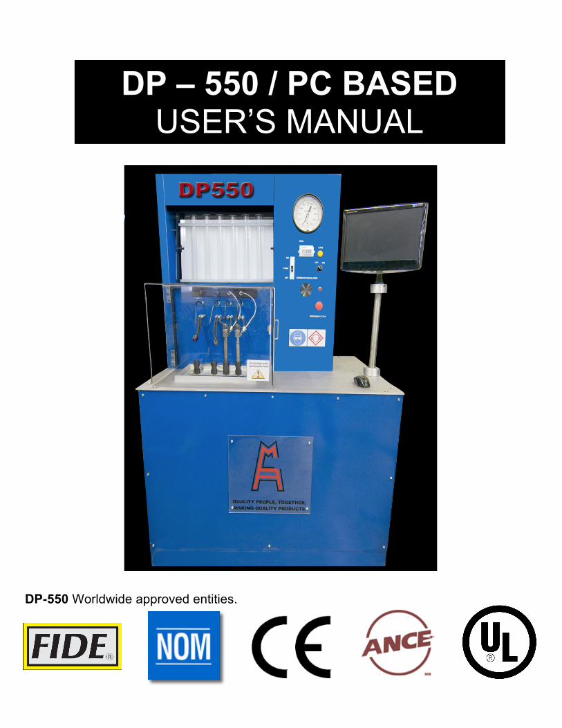
DP-550 Worldwide approved entities.
DP – 550 / PC BASED USER’S MANUAL
M MANUAL

DIESEL PARTS OF AMERICA 13150 Leadwell Street, N. Hollywood, California, 91605 U.S.A.
2
TABLE OF CONTENTS INTRODUCTION……………………………………………………………………PAGE 3 GENERAL INFORMATION……………………………………………………..…PAGE 4 TESTING PARAMETER BLOCK DIAGRAM…………………………………….PAGE 5 INSTALLATION……………………………………………………………………..PAGE 6 PC LINK INFORMATION……………………………………………………..……PAGE 9 TESTING METHOD AND PARTS……………………………………………...…PAGE 10 PC PROGRAMS…………………………………………………………………….PAGE 12 CR INJECTOR TESTS……………………………………………………………..PAGE 14 INJECTOR TESTING RECOMMENDATIONS…………………………………..PAGE 25 TROUBLESHOOTING……………………………………………………………...PAGE 26 MANTEINANCE……………………………………………………………………..PAGE 29 MAJOR TROUBLESHOOTING…………………………………………….……..PAGE 30 NOTES……………………………………………………………………………….PAGE 31
DIESEL PARTS OF AMERICA 13150 Leadwell Street, N. Hollywood, California, 91605 U.S.A.
3
Introduction Thank you for your recent DP-550 purchase. We appreciate your business and are pleased to add your name to our growing list of customers. You have invested in the highest quality equipment available. Now, please take a few minutes and read this booklet. This will familiarize you with the benefits you will receive from the equipment you just purchased and help you understand the testing routine that will be required. This manual has been prepared specially for use in familiarizing personnel with the design, installation and operation of this equipment. All information presented herein should be given careful consideration to assure optimum performance of this equipment. All information, illustrations, photographs and specifications contained in this manual are based on the latest product information available at the time of publication. Due to improvements or other changes, there will be some discrepancies in this manual. We reserve the right to make product changes at any time, without notice and without incurring any obligation to make the same or similar changes to the tester previously built or sold.
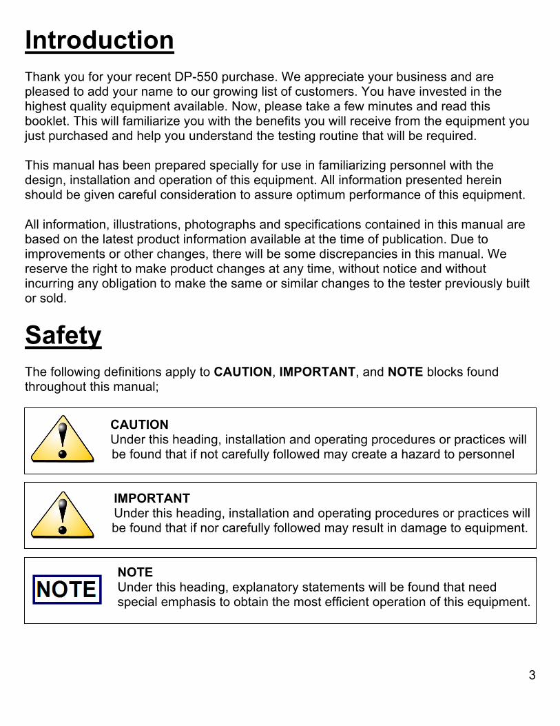
Safety The following definitions apply to CAUTION, IMPORTANT, and NOTE blocks found throughout this manual;
CAUTION Under this heading, installation and operating procedures or practices will sssssssssssss be found that if not carefully followed may create a hazard to personnel IMPORTANT Under this heading, installation and operating procedures or practices will sssssssssssss be found that if nor carefully followed may result in damage to equipment. NOTE Under this heading, explanatory statements will be found that need dddddddddddddspecial emphasis to obtain the most efficient operation of this equipment.
DIESEL PARTS OF AMERICA 13150 Leadwell Street, N. Hollywood, California, 91605 U.S.A.
4
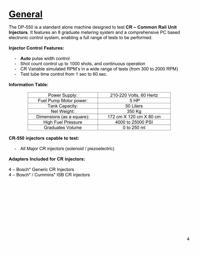
General The DP-550 is a standard alone machine designed to test CR – Common Rail Unit Injectors. It features an 8 graduate metering system and a comprehensive PC based electronic control system, enabling a full range of tests to be performed. Injector Control Features:
- Auto pulse width control - Shot count control up to 1000 shots, and continuous operation - CR Variable simulated RPM’s in a wide range of tests (from 300 to 2000 RPM) - Test tube time control from 1 sec to 60 sec.
Information Table:
Power Supply: 210-220 Volts, 60 Hertz Fuel Pump Motor power: 5 HP
Tank Capacity: 50 Liters Net Weight: 350 Kg
Dimensions (as a square): 172 cm X 120 cm X 80 cm High Fuel Pressure 4000 to 25000 PSI Graduates Volume 0 to 250 ml
CR-550 injectors capable to test:
- All Major CR injectors (solenoid / piezoelectric) Adapters Included for CR injectors: 4 – Bosch* Generic CR Injectors 4 – Bosch* / Cummins* ISB CR injectors
DIESEL PARTS OF AMERICA 13150 Leadwell Street, N. Hollywood, California, 91605 U.S.A.
5
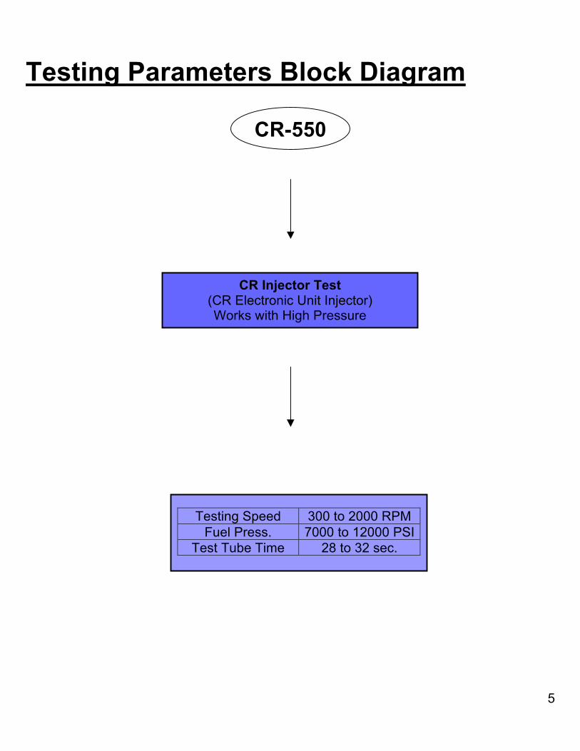
Testing Parameters Block Diagram
CR-550
CR Injector Test (CR Electronic Unit Injector) Works with High Pressure
Testing Speed 300 to 2000 RPM Fuel Press. 7000 to 12000 PSI
Test Tube Time 28 to 32 sec.
DIESEL PARTS OF AMERICA 13150 Leadwell Street, N. Hollywood, California, 91605 U.S.A.
6
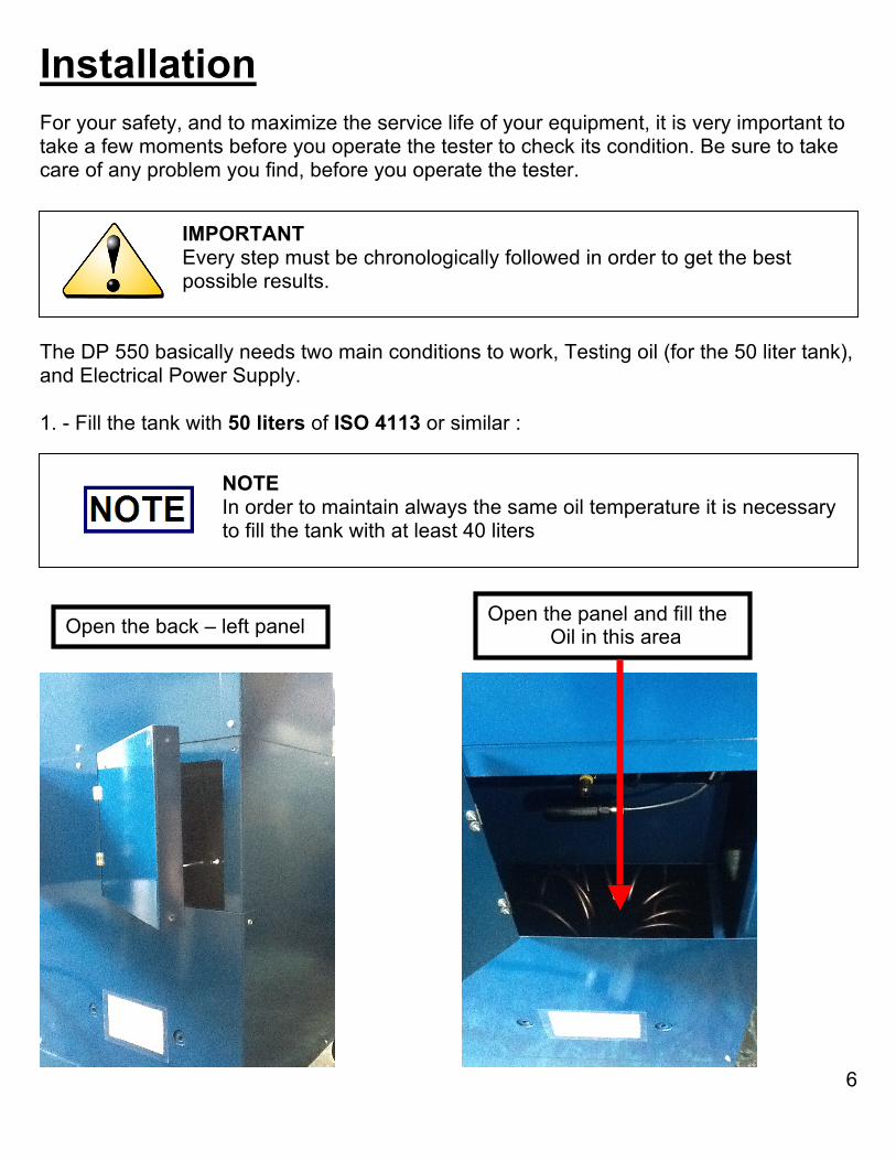
Installation For your safety, and to maximize the service life of your equipment, it is very important to take a few moments before you operate the tester to check its condition. Be sure to take care of any problem you find, before you operate the tester. IMPORTANT Every step must be chronologically followed in order to get the best ddddddddddd possible results. The DP 550 basically needs two main conditions to work, Testing oil (for the 50 liter tank), and Electrical Power Supply. 1. - Fill the tank with 50 liters of ISO 4113 or similar :
NOTE In order to maintain always the same oil temperature it is necessary ddddddddddddddddto fill the tank with at least 40 liters
Fill the oil in this area Open the panel and fill the Oil in this area Open the back – left panel
DIESEL PARTS OF AMERICA 13150 Leadwell Street, N. Hollywood, California, 91605 U.S.A.
7
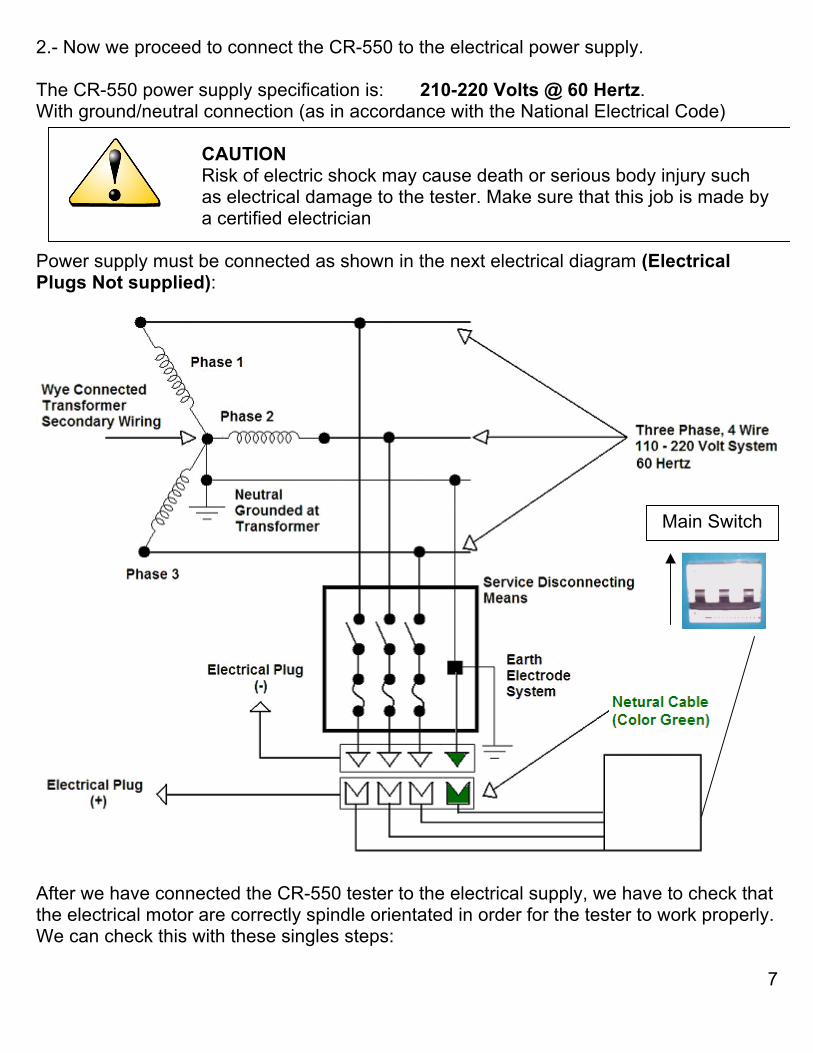
2.- Now we proceed to connect the CR-550 to the electrical power supply. The CR-550 power supply specification is: 210-220 Volts @ 60 Hertz. With ground/neutral connection (as in accordance with the National Electrical Code) CAUTION Risk of electric shock may cause death or serious body injury such ddddddddddddddddas electrical damage to the tester. Make sure that this job is made by ................................a certified electrician Power supply must be connected as shown in the next electrical diagram (Electrical Plugs Not supplied):
After we have connected the CR-550 tester to the electrical supply, we have to check that the electrical motor are correctly spindle orientated in order for the tester to work properly. We can check this with these singles steps:
Main Switch
DIESEL PARTS OF AMERICA 13150 Leadwell Street, N. Hollywood, California, 91605 U.S.A.
8
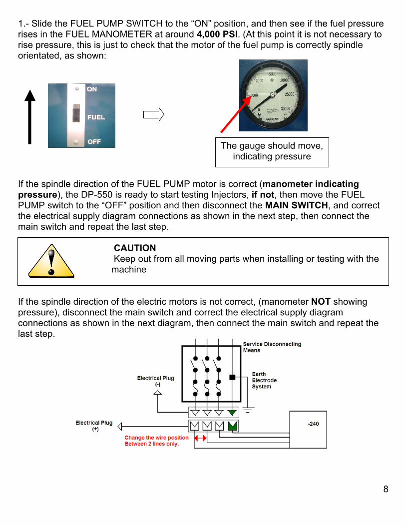
1.- Slide the FUEL PUMP SWITCH to the “ON” position, and then see if the fuel pressure rises in the FUEL MANOMETER at around 4,000 PSI. (At this point it is not necessary to rise pressure, this is just to check that the motor of the fuel pump is correctly spindle orientated, as shown: If the spindle direction of the FUEL PUMP motor is correct (manometer indicating pressure), the DP-550 is ready to start testing Injectors, if not, then move the FUEL PUMP switch to the “OFF” position and then disconnect the MAIN SWITCH, and correct the electrical supply diagram connections as shown in the next step, then connect the main switch and repeat the last step.
CAUTION Keep out from all moving parts when installing or testing with the ddddddddddddd machine
If the spindle direction of the electric motors is not correct, (manometer NOT showing pressure), disconnect the main switch and correct the electrical supply diagram connections as shown in the next diagram, then connect the main switch and repeat the last step.
The gauge should move, indicating pressure
DIESEL PARTS OF AMERICA 13150 Leadwell Street, N. Hollywood, California, 91605 U.S.A.
9
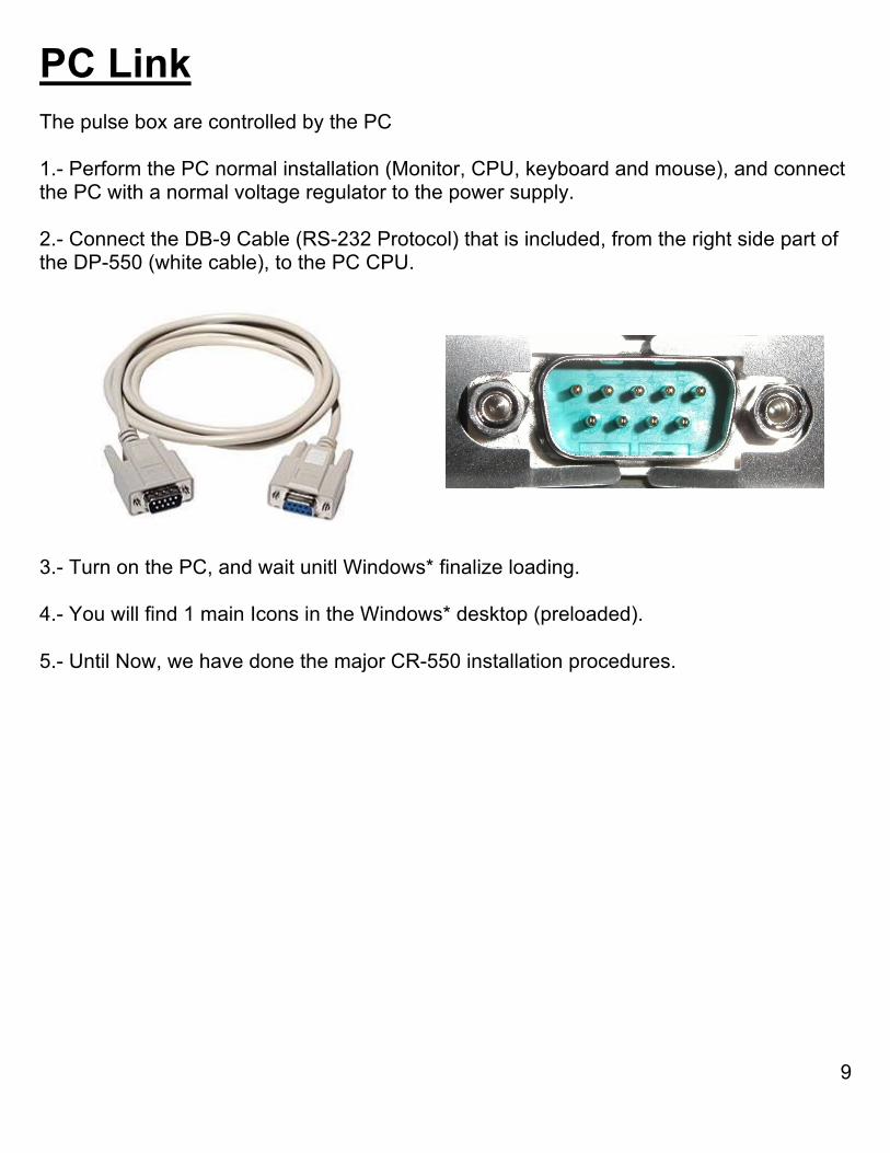
PC Link The pulse box are controlled by the PC 1.- Perform the PC normal installation (Monitor, CPU, keyboard and mouse), and connect the PC with a normal voltage regulator to the power supply. 2.- Connect the DB-9 Cable (RS-232 Protocol) that is included, from the right side part of the DP-550 (white cable), to the PC CPU.
3.- Turn on the PC, and wait unitl Windows* finalize loading. 4.- You will find 1 main Icons in the Windows* desktop (preloaded). 5.- Until Now, we have done the major CR-550 installation procedures.
DIESEL PARTS OF AMERICA 13150 Leadwell Street, N. Hollywood, California, 91605 U.S.A.
10
DP-550 testing method and Parts For testing CR injectors, this is the main methodology: IMPORTANT Every step must be chronologically followed in order to get the best ddddddddddd possible results.
1.- Clean the injector / injectors in its internal / external parts, before testing, to avoid oil / filter contamination.
2.- Place the injector / injectors in its testing places with its accessories (High pressure piping, adapters, etc) and connect the wiring harnesses provided
3.- Turn on the Pulse Generator Box and run the PC based program 4.- Turn on the fuel pump, and rise to the desired pressure value.
5.- Check the fuel delivery in the test tubes. 7.- After finishing the test / tests, turn off the fuel pump 9.- Turn off the Pulse Generator Box, PC and Main Switch after all the testing has ........ been performed 10.- Place their accessories / protective case
DIESEL PARTS OF AMERICA 13150 Leadwell Street, N. Hollywood, California, 91605 U.S.A.
11
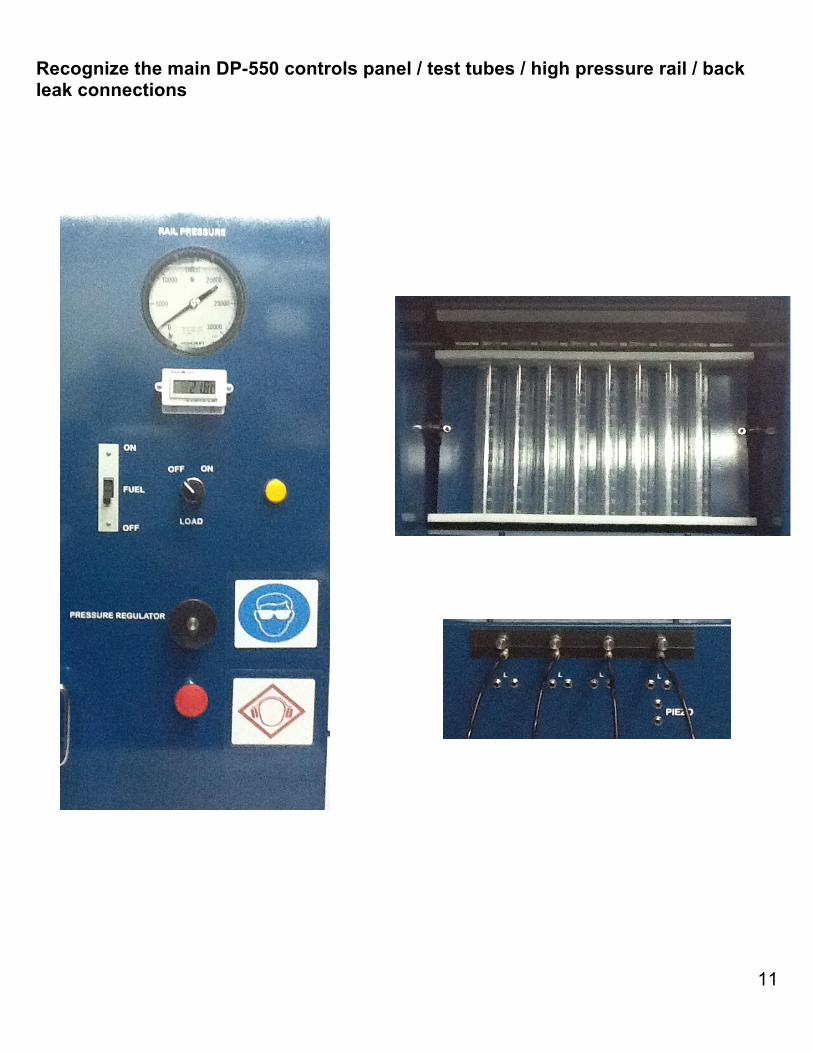
Recognize the main DP-550 controls panel / test tubes / high pressure rail / back leak connections
DIESEL PARTS OF AMERICA 13150 Leadwell Street, N. Hollywood, California, 91605 U.S.A.
12
PC Programs. (CR) description These descriptions will explain how to use the programs for testing CR injectors in the DP-550. These explanations should be taken in consideration on later testing procedures posted on this user’s manual. CR Program 1.- Once the PC Link Installation is complete (page 9), now we proceed to open the CR program located in the windows* desktop from the PC provided with the DP-550, giving “double clic” in the “DP-550” icon 2.- A “Port 1 was open” legend should appear, then we give “one clic” to the “ok” button.
DIESEL PARTS OF AMERICA 13150 Leadwell Street, N. Hollywood, California, 91605 U.S.A.
13
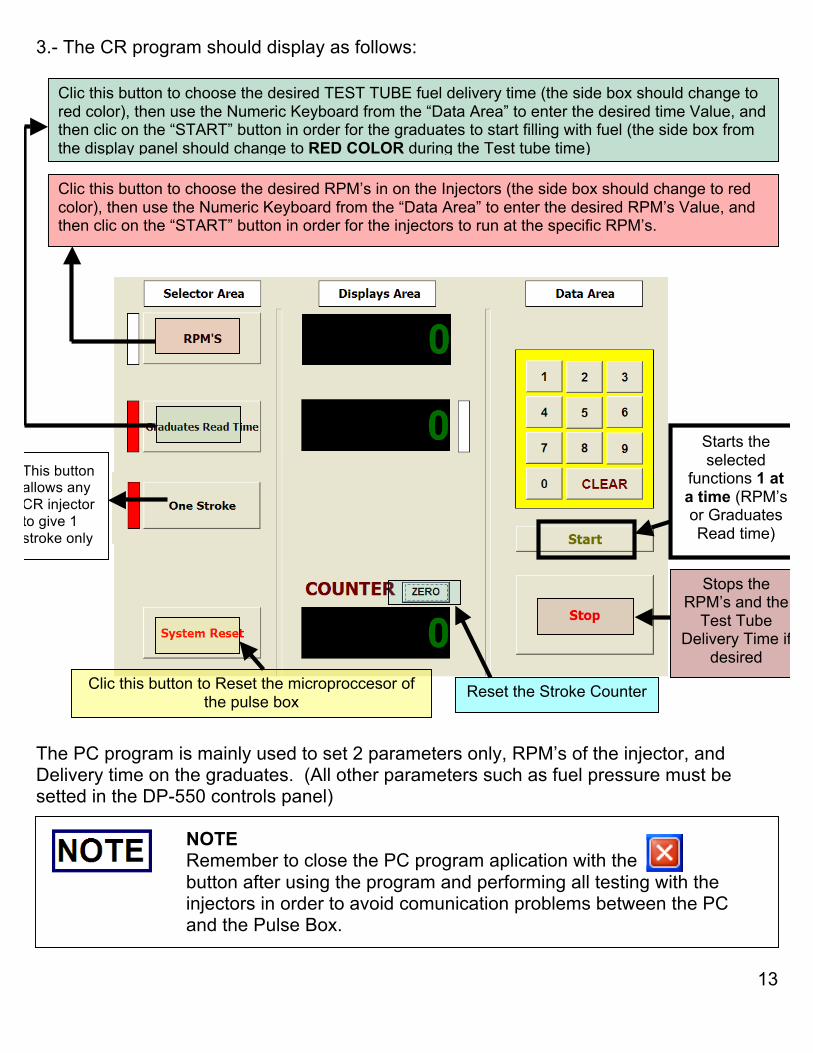
3.- The CR program should display as follows:
The PC program is mainly used to set 2 parameters only, RPM’s of the injector, and Delivery time on the graduates. (All other parameters such as fuel pressure must be setted in the DP-550 controls panel)
NOTE Remember to close the PC program aplication with the button after using the program and performing all testing with the injectors in order to avoid comunication problems between the PC and the Pulse Box.
Clic this button to choose the desired RPM’s in on the Injectors (the side box should change to red color), then use the Numeric Keyboard from the “Data Area” to enter the desired RPM’s Value, and then clic on the “START” button in order for the injectors to run at the specific RPM’s.
Clic this button to choose the desired TEST TUBE fuel delivery time (the side box should change to red color), then use the Numeric Keyboard from the “Data Area” to enter the desired time Value, and then clic on the “START” button in order for the graduates to start filling with fuel (the side box from the display panel should change to RED COLOR during the Test tube time)
Clic this button to Reset the microproccesor of the pulse box Reset the Stroke Counter
Stops the RPM’s and the
Test Tube Delivery Time if
desired
Starts the selected
functions 1 at a time (RPM’s or Graduates Read time)
This button allows any CR injector to give 1 stroke only
DIESEL PARTS OF AMERICA 13150 Leadwell Street, N. Hollywood, California, 91605 U.S.A.
14
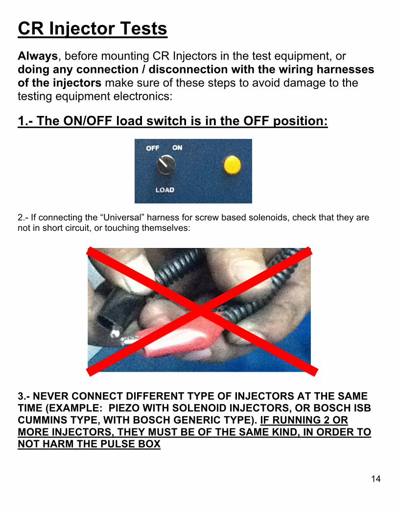
CR Injector Tests Always, before mounting CR Injectors in the test equipment, or doing any connection / disconnection with the wiring harnesses of the injectors make sure of these steps to avoid damage to the testing equipment electronics: 1.- The ON/OFF load switch is in the OFF position: 2.- If connecting the “Universal” harness for screw based solenoids, check that they are not in short circuit, or touching themselves: 3.- NEVER CONNECT DIFFERENT TYPE OF INJECTORS AT THE SAME TIME (EXAMPLE: PIEZO WITH SOLENOID INJECTORS, OR BOSCH ISB CUMMINS TYPE, WITH BOSCH GENERIC TYPE). IF RUNNING 2 OR MORE INJECTORS, THEY MUST BE OF THE SAME KIND, IN ORDER TO NOT HARM THE PULSE BOX
DIESEL PARTS OF AMERICA 13150 Leadwell Street, N. Hollywood, California, 91605 U.S.A.
15
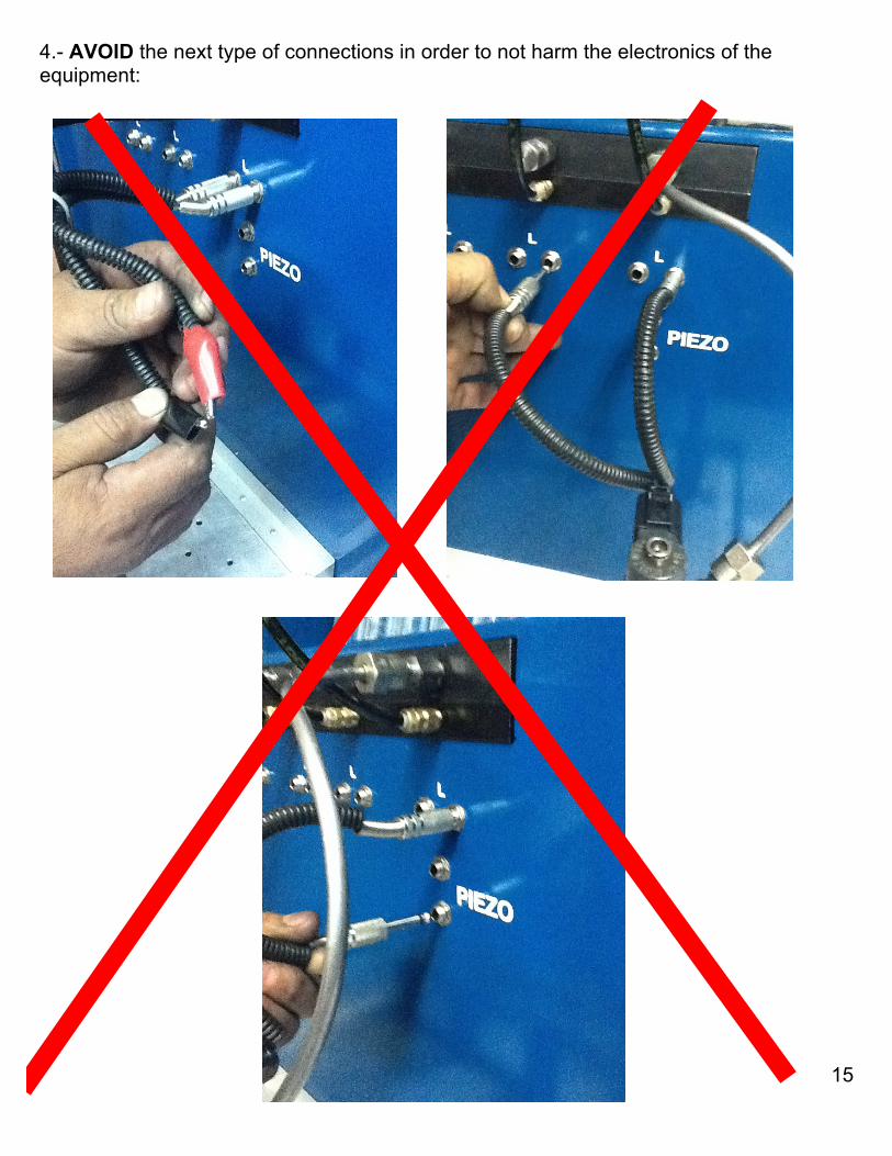
4.- AVOID the next type of connections in order to not harm the electronics of the equipment:
DIESEL PARTS OF AMERICA 13150 Leadwell Street, N. Hollywood, California, 91605 U.S.A.
16
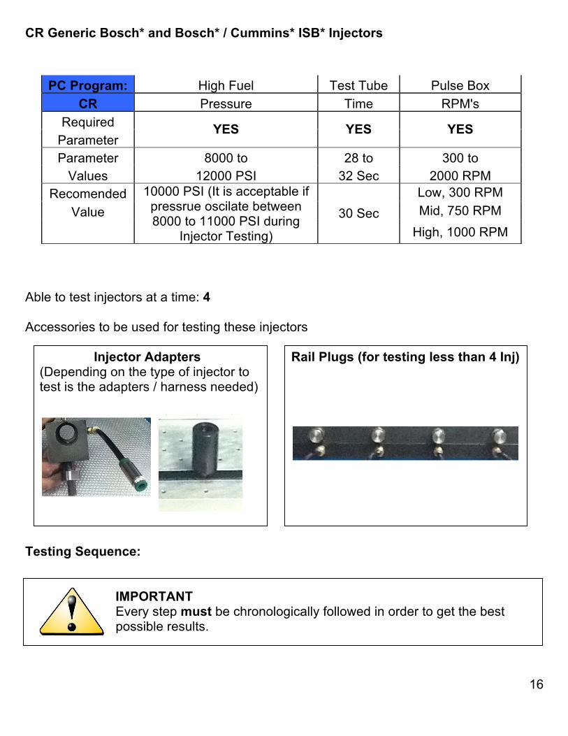
CR Generic Bosch* and Bosch* / Cummins* ISB* Injectors
Able to test injectors at a time: 4 Accessories to be used for testing these injectors Injector Adapters Rail Plugs (for testing less than 4 Inj) (Depending on the type of injector to test is the adapters / harness needed) Testing Sequence: IMPORTANT Every step must be chronologically followed in order to get the best ddddddddddd possible results.
PC Program: High Fuel Test Tube Pulse Box CR Pressure Time RPM's
Required Parameter
YES YES YES
Parameter 8000 to 28 to 300 to Values 12000 PSI 32 Sec 2000 RPM
Recomended Low, 300 RPM Value Mid, 750 RPM
10000 PSI (It is acceptable if pressrue oscilate between 8000 to 11000 PSI during
Injector Testing)
30 Sec High, 1000 RPM
DIESEL PARTS OF AMERICA 13150 Leadwell Street, N. Hollywood, California, 91605 U.S.A.
17
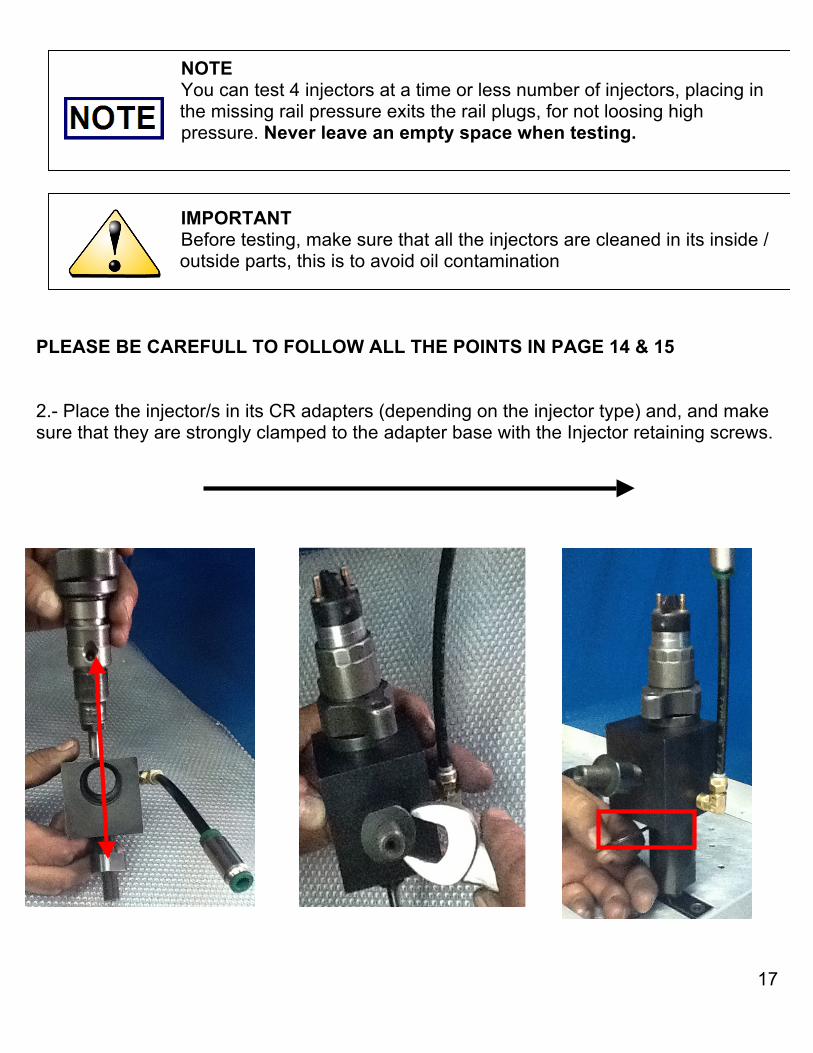
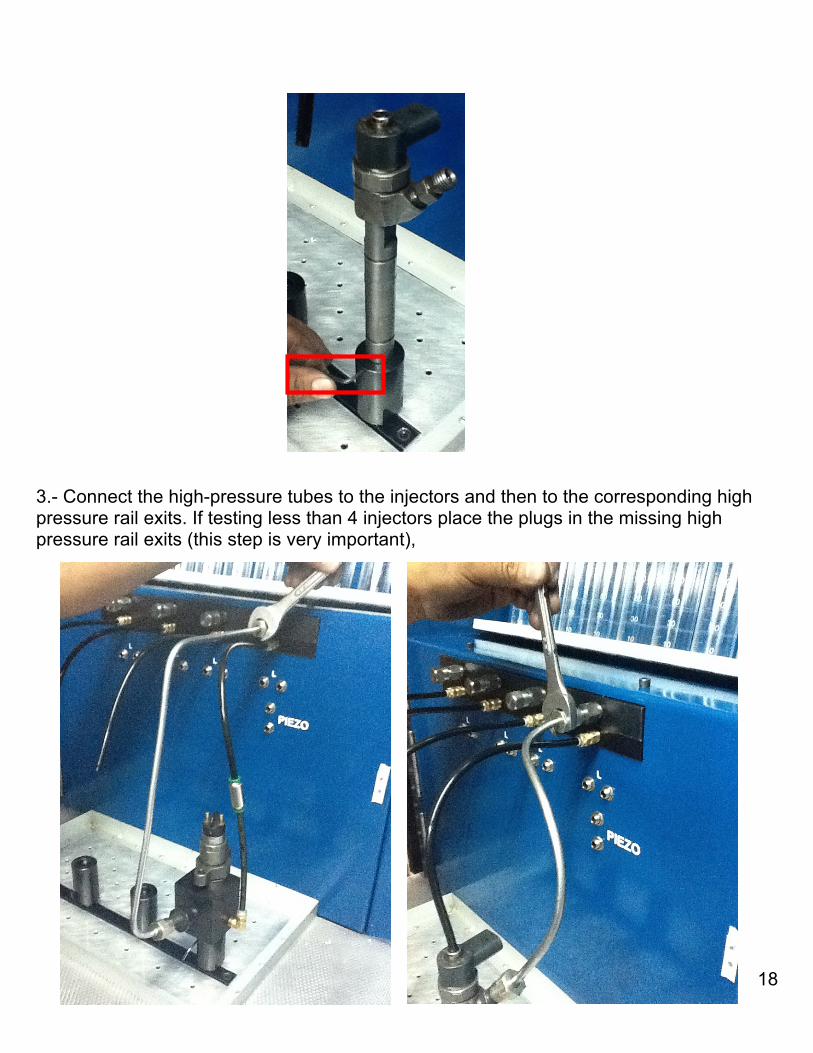
NOTE You can test 4 injectors at a time or less number of injectors, placing in sssssssssssssssithe missing rail pressure exits the rail plugs, for not loosing high ddddddddddddddpressure. Never leave an empty space when testing. IMPORTANT Before testing, make sure that all the injectors are cleaned in its inside / sssssssssssssssioutside parts, this is to avoid oil contamination PLEASE BE CAREFULL TO FOLLOW ALL THE POINTS IN PAGE 14 & 15 2.- Place the injector/s in its CR adapters (depending on the injector type) and, and make sure that they are strongly clamped to the adapter base with the Injector retaining screws.
DIESEL PARTS OF AMERICA 13150 Leadwell Street, N. Hollywood, California, 91605 U.S.A.
18
3.- Connect the high-pressure tubes to the injectors and then to the corresponding high pressure rail exits. If testing less than 4 injectors place the plugs in the missing high pressure rail exits (this step is very important),
DIESEL PARTS OF AMERICA 13150 Leadwell Street, N. Hollywood, California, 91605 U.S.A.
19
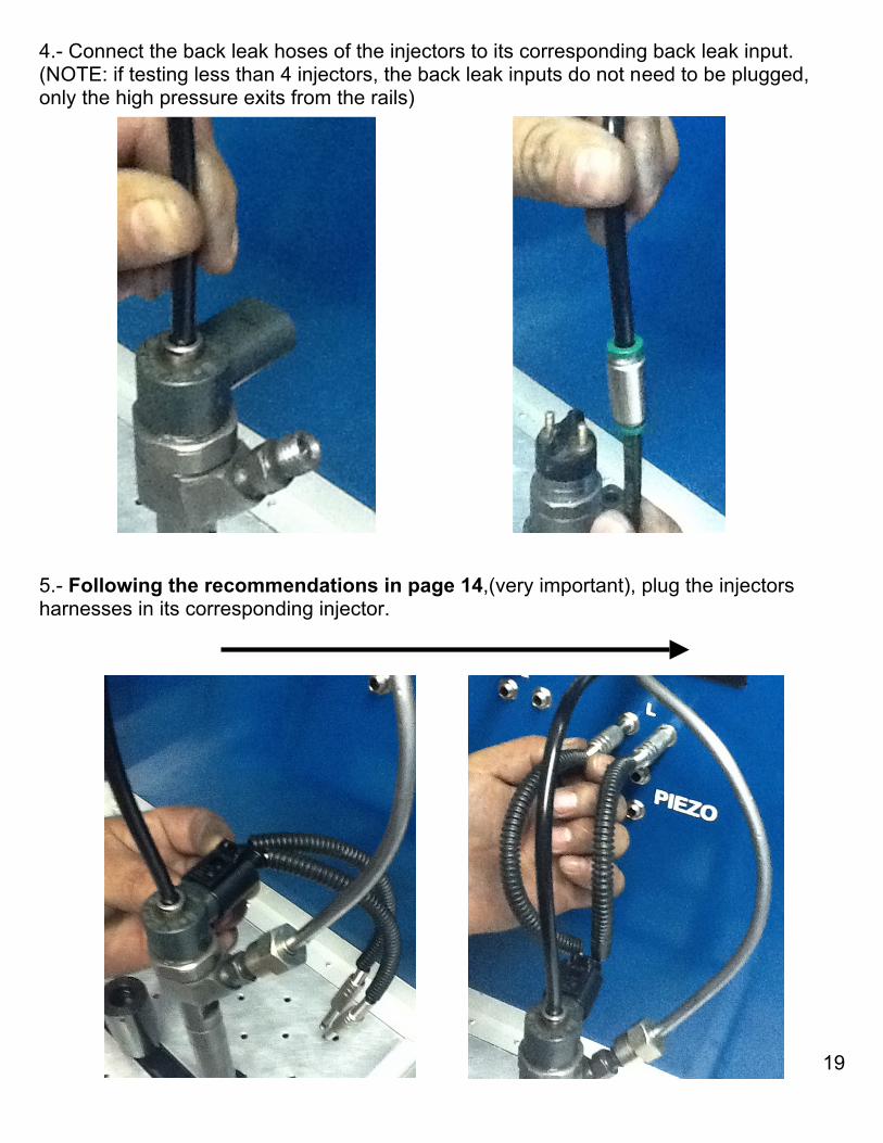
4.- Connect the back leak hoses of the injectors to its corresponding back leak input. (NOTE: if testing less than 4 injectors, the back leak inputs do not need to be plugged, only the high pressure exits from the rails) 5.- Following the recommendations in page 14,(very important), plug the injectors harnesses in its corresponding injector.

DIESEL PARTS OF AMERICA 13150 Leadwell Street, N. Hollywood, California, 91605 U.S.A.
20
6.- Close the protective case where the injectors are located IN ORDER TO AVOID ANY INJURY IN CASE OF EMERGENCY (PLEASE LOCATE THE EMERGENCY BUTTON IN THE FRONT PANEL IN CASE OF EMERGENY). 7.- Move the Fuel Pressure switch to “ON” position, and rise the fuel pressure with the fuel pressure valve (moving clockwise) to the desired fuel pressure (we recommend 10000 PSI) as shown in picture.
DIESEL PARTS OF AMERICA 13150 Leadwell Street, N. Hollywood, California, 91605 U.S.A.
21
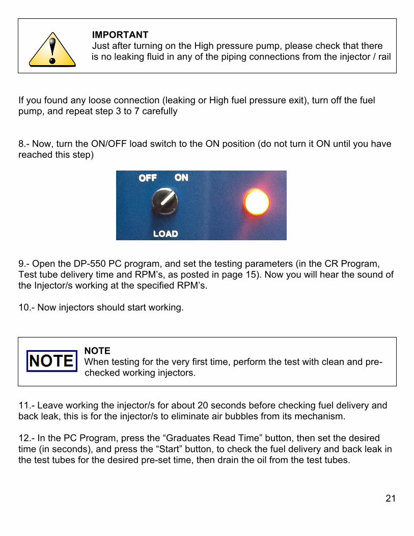
IMPORTANT Just after turning on the High pressure pump, please check that there sssssssssssssssiis no leaking fluid in any of the piping connections from the injector / rail If you found any loose connection (leaking or High fuel pressure exit), turn off the fuel pump, and repeat step 3 to 7 carefully 8.- Now, turn the ON/OFF load switch to the ON position (do not turn it ON until you have reached this step) 9.- Open the DP-550 PC program, and set the testing parameters (in the CR Program, Test tube delivery time and RPM’s, as posted in page 15). Now you will hear the sound of the Injector/s working at the specified RPM’s. 10.- Now injectors should start working. NOTE When testing for the very first time, perform the test with clean and pre-cssssssssssssi checked working injectors. 11.- Leave working the injector/s for about 20 seconds before checking fuel delivery and back leak, this is for the injector/s to eliminate air bubbles from its mechanism. 12.- In the PC Program, press the “Graduates Read Time” button, then set the desired time (in seconds), and press the “Start” button, to check the fuel delivery and back leak in the test tubes for the desired pre-set time, then drain the oil from the test tubes.
DIESEL PARTS OF AMERICA 13150 Leadwell Street, N. Hollywood, California, 91605 U.S.A.
22
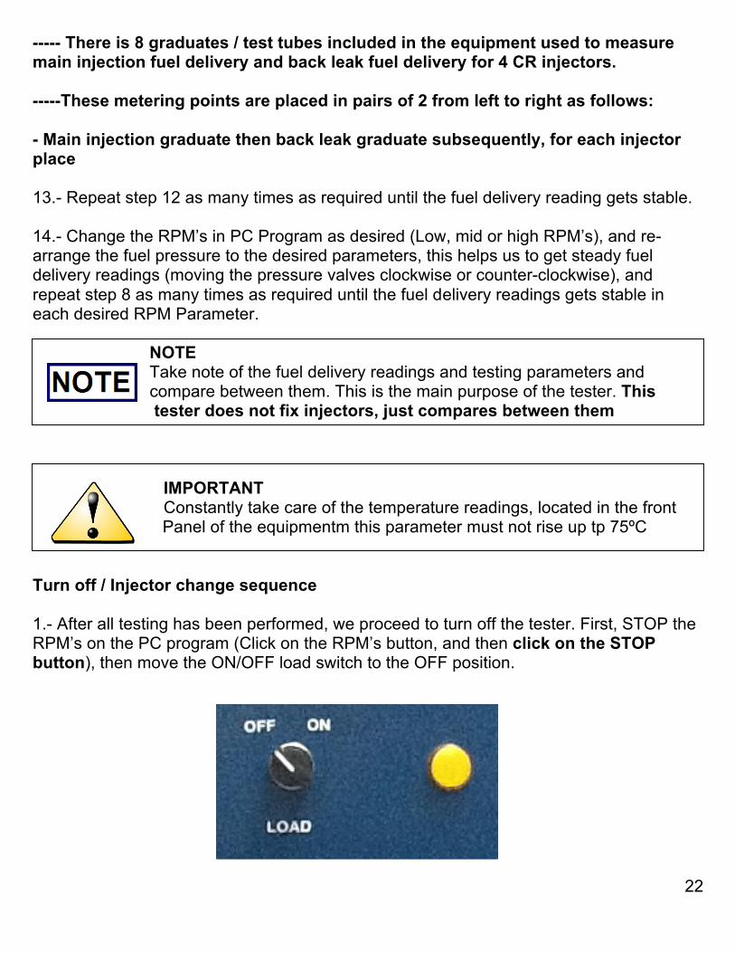
----- There is 8 graduates / test tubes included in the equipment used to measure main injection fuel delivery and back leak fuel delivery for 4 CR injectors. -----These metering points are placed in pairs of 2 from left to right as follows: - Main injection graduate then back leak graduate subsequently, for each injector place 13.- Repeat step 12 as many times as required until the fuel delivery reading gets stable. 14.- Change the RPM’s in PC Program as desired (Low, mid or high RPM’s), and re-arrange the fuel pressure to the desired parameters, this helps us to get steady fuel delivery readings (moving the pressure valves clockwise or counter-clockwise), and repeat step 8 as many times as required until the fuel delivery readings gets stable in each desired RPM Parameter. NOTE Take note of the fuel delivery readings and testing parameters and dddddddddddd compare between them. This is the main purpose of the tester. This itester does not fix injectors, just compares between them IMPORTANT Constantly take care of the temperature readings, located in the front sssssssssssssssiPanel of the equipmentm this parameter must not rise up tp 75ºC Turn off / Injector change sequence 1.- After all testing has been performed, we proceed to turn off the tester. First, STOP the RPM’s on the PC program (Click on the RPM’s button, and then click on the STOP button), then move the ON/OFF load switch to the OFF position.
DIESEL PARTS OF AMERICA 13150 Leadwell Street, N. Hollywood, California, 91605 U.S.A.
23
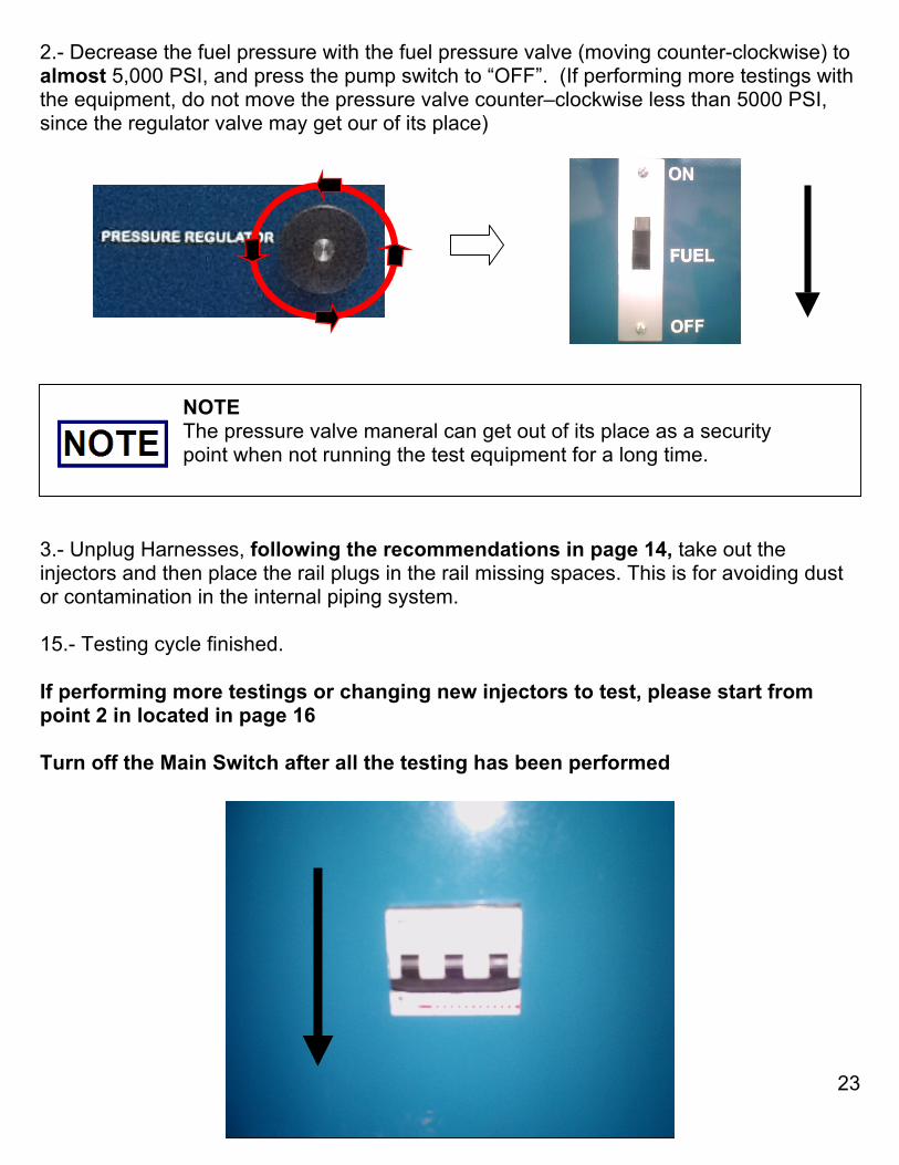
2.- Decrease the fuel pressure with the fuel pressure valve (moving counter-clockwise) to almost 5,000 PSI, and press the pump switch to “OFF”. (If performing more testings with the equipment, do not move the pressure valve counter–clockwise less than 5000 PSI, since the regulator valve may get our of its place) NOTE The pressure valve maneral can get out of its place as a security dddddddddddd point when not running the test equipment for a long time. 3.- Unplug Harnesses, following the recommendations in page 14, take out the injectors and then place the rail plugs in the rail missing spaces. This is for avoiding dust or contamination in the internal piping system. 15.- Testing cycle finished. If performing more testings or changing new injectors to test, please start from point 2 in located in page 16 Turn off the Main Switch after all the testing has been performed
DIESEL PARTS OF AMERICA 13150 Leadwell Street, N. Hollywood, California, 91605 U.S.A.
24
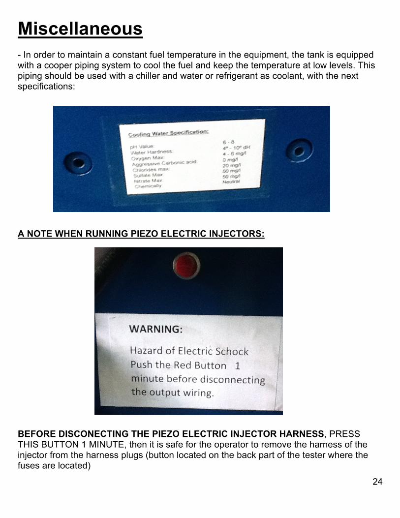
Miscellaneous - In order to maintain a constant fuel temperature in the equipment, the tank is equipped with a cooper piping system to cool the fuel and keep the temperature at low levels. This piping should be used with a chiller and water or refrigerant as coolant, with the next specifications:
A NOTE WHEN RUNNING PIEZO ELECTRIC INJECTORS: BEFORE DISCONECTING THE PIEZO ELECTRIC INJECTOR HARNESS, PRESS THIS BUTTON 1 MINUTE, then it is safe for the operator to remove the harness of the injector from the harness plugs (button located on the back part of the tester where the fuses are located)
DIESEL PARTS OF AMERICA 13150 Leadwell Street, N. Hollywood, California, 91605 U.S.A.
25
Injector Testing Please, take care of the next following recommendations: - Please check the “Auto Pulse Width Techonlogy.pdf” and the “PW vs RPM Table.xls” files, in order for the operator to understand the relation of the Pulse width and the RPM’s (this file is valid for CR injectors in this DP-550 tester only). 1.- The general purpose of the DP-550 Injector Tester is to obtain a fuel delivery and back leak metering parameter of an injector in a certain amount of time with a set of parameters (fuel pressure, oil pressure, test tube time, etc), in order to compare them with other injectors of the same type or to check the performance of its internal parts. Remember that this tester does not fix injectors, IT ONLY COMPARE BETWEEN THEM, that is why we recommend to follow the next steps in order to be successful in repairing, rebuilding / reconstructing these injectors:
- From the beginning, do not vary the user’s established main parameters of the tester (these parameters can be obtained by the every day’s operator experience with the tester, or the ones we recommend in the original manual.) For example: If the user (that has already experience with the tester), determines that a certain Injector (can be any of the fuel systems posted in the original manual) has a fuel delivery of 60 ml, with a certain amount of fuel pressure, etc. We recommend the operator not to vary these parameters, in order for him to always get the same STEADY fuel reading to determine if an injector is really performing as desired or not. If the operator finds that with its parameters (fuel pressure, test tube time, etc) the injectors deliver more o less fuel, this is indicating him that the injector has something wrong with it.
- The information of fuel delivery and testing parameters for these electronic injectors
is not available for any diesel shop, or aftermarket equipment manufacturer, so this is why we recommend to perform a testing parameter / fuel delivery table with a “Master Injector” (a master injector can be a new injector, or an injector that the user knows of its correct performance). The way we recommend to develop a “Master Table” with a “Master injector”, is to gather the fuel delivery information of a NEW injector that has the same characteristics of the ones the user wants to rebuild / reconstruct / repair, at different parameters (Fuel Pressure, RPM’s, test tube time, etc)
- The key for making a successful injector repair / rebuild / reconstruction, is to
simulate the same performance of a “Master Injector” in its parameters (Fuel Delivery, RPM’s, Fuel Pressure, test tube time, etc)
DIESEL PARTS OF AMERICA 13150 Leadwell Street, N. Hollywood, California, 91605 U.S.A.
26
Troubleshooting If the operator finds something wrong with the DP-550 tester when working, (for example: Fuel delivery pan does not returns to its initial place after the test tubes delivery times has ended or when pressing the “Start test” button the fuel pan does not react) usually what the operator only has to do is to press the System Reset Button located in the PC Program panel (page 13), and everything should be corrected. In order to keep save the manometer from excessive pressures values that may harm the equipment pressure metering system. It is recommendable NOT to take the tester to its parameter limits (excessive fuel pressure during long operation time) If one or several injectors has short circuited coils (bad coils / solenoids), this may cause the injector fuses to brake (located in the back part of the pulse box), not allowing to perform more test in future. So it is STRONGLY RECOMMENDABLE to check the continuity of the fuses if an injector is not working. If you find any breaked fuse, please REPLACE IT WITH A FUSE OF THE SAME AMPERAGE VALUE.
CAUTION If a fuse is broken, ALWAYS REPLACE IT WITH A SAME VALUE dddddd ddd FUSE, never change the fuses values since the pulse box is designed to work with no more amperage than the prestablished in the fuses. A NOT ALLOWED FUSE AMPERAGE VALUE REPLACED IN THE PULSE BOX, MAY CAUSE THE PERMANENT DAMAGE OF THE PULSE BOX MICROPROCCESSOR
DIESEL PARTS OF AMERICA 13150 Leadwell Street, N. Hollywood, California, 91605 U.S.A.
27
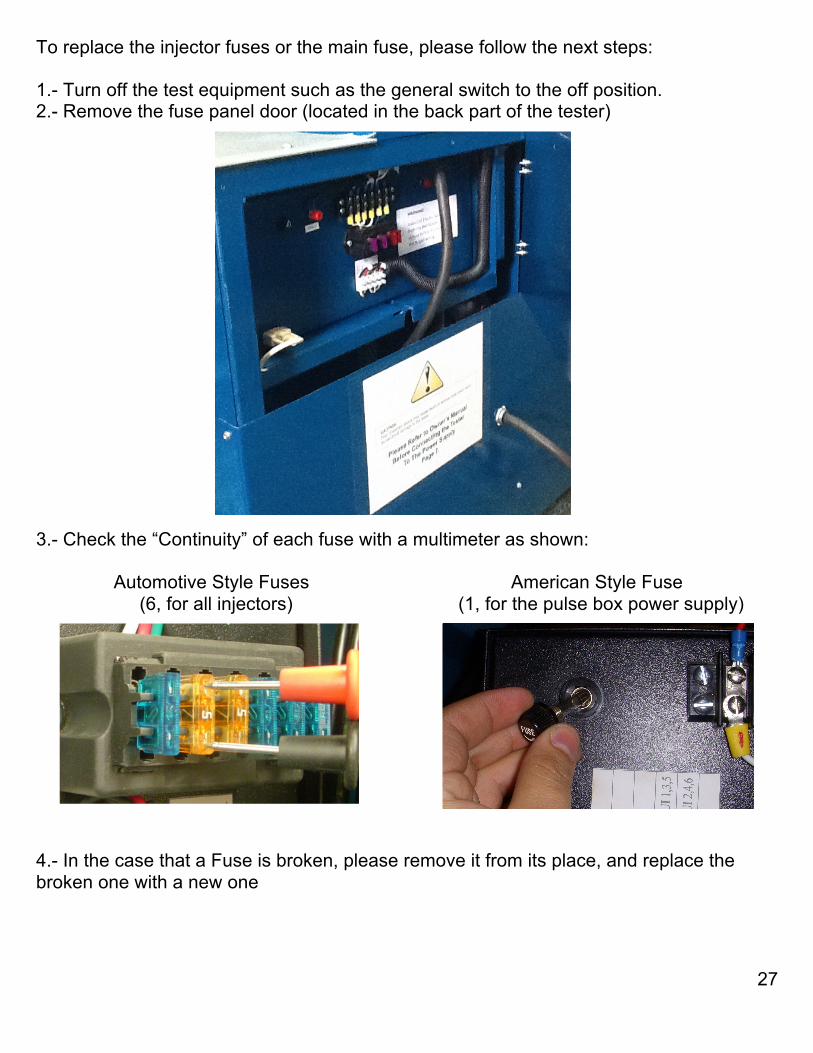
To replace the injector fuses or the main fuse, please follow the next steps: 1.- Turn off the test equipment such as the general switch to the off position. 2.- Remove the fuse panel door (located in the back part of the tester) 3.- Check the “Continuity” of each fuse with a multimeter as shown: Automotive Style Fuses American Style Fuse (6, for all injectors) (1, for the pulse box power supply) 4.- In the case that a Fuse is broken, please remove it from its place, and replace the broken one with a new one
DIESEL PARTS OF AMERICA 13150 Leadwell Street, N. Hollywood, California, 91605 U.S.A.
28
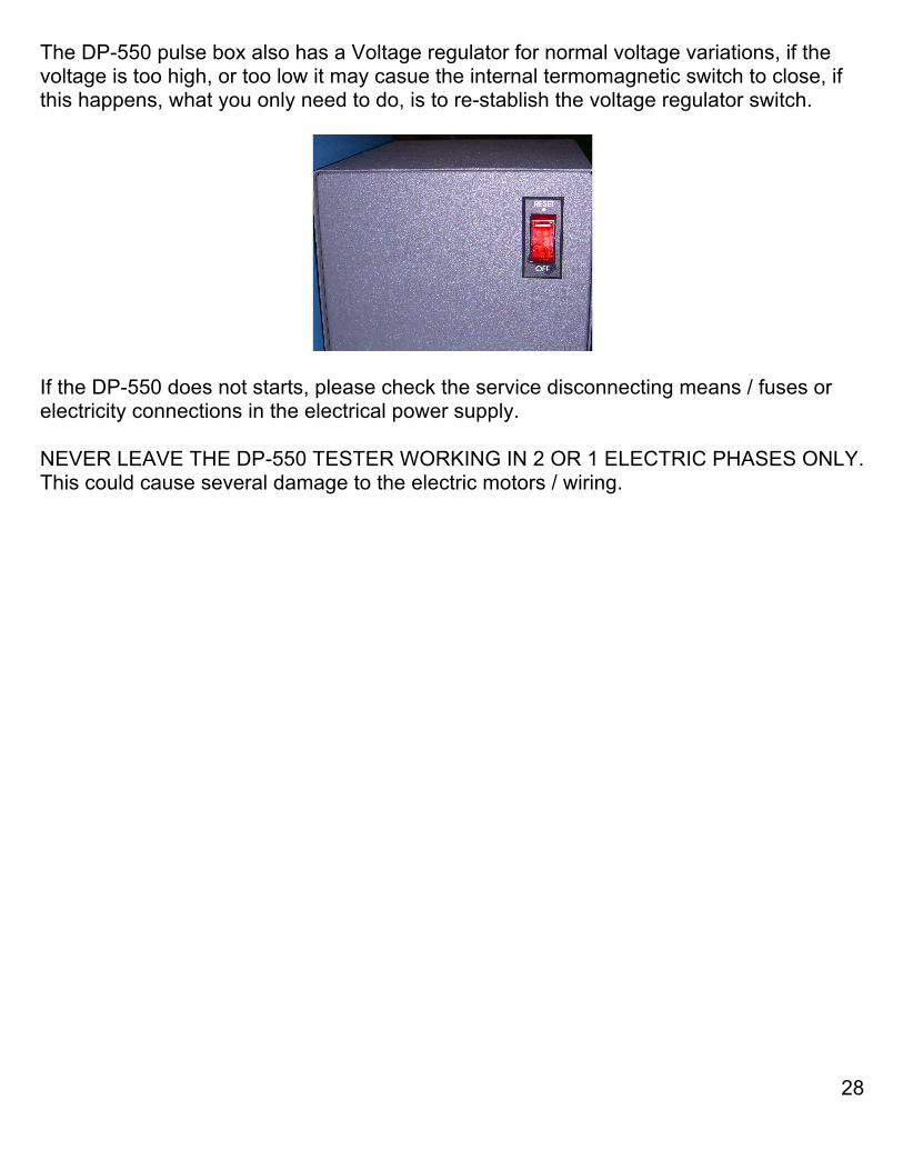
The DP-550 pulse box also has a Voltage regulator for normal voltage variations, if the voltage is too high, or too low it may casue the internal termomagnetic switch to close, if this happens, what you only need to do, is to re-stablish the voltage regulator switch.
If the DP-550 does not starts, please check the service disconnecting means / fuses or electricity connections in the electrical power supply. NEVER LEAVE THE DP-550 TESTER WORKING IN 2 OR 1 ELECTRIC PHASES ONLY. This could cause several damage to the electric motors / wiring.
DIESEL PARTS OF AMERICA 13150 Leadwell Street, N. Hollywood, California, 91605 U.S.A.
29
Maintenance It is recommendable to change the ISO 4113 or similar oil and the oil filters from the tank every 300 hours of operation (about 1 year). In order to proceed with the manteinance service, we must follow the next steps: Oil, and oil Filters change. 1.- Remove the back panel door where the tank is located 2.- Remove the oil from the 50 liter tank 3.- Disassembly the oil filter protection, and remove the filter
DIESEL PARTS OF AMERICA 13150 Leadwell Street, N. Hollywood, California, 91605 U.S.A.
30
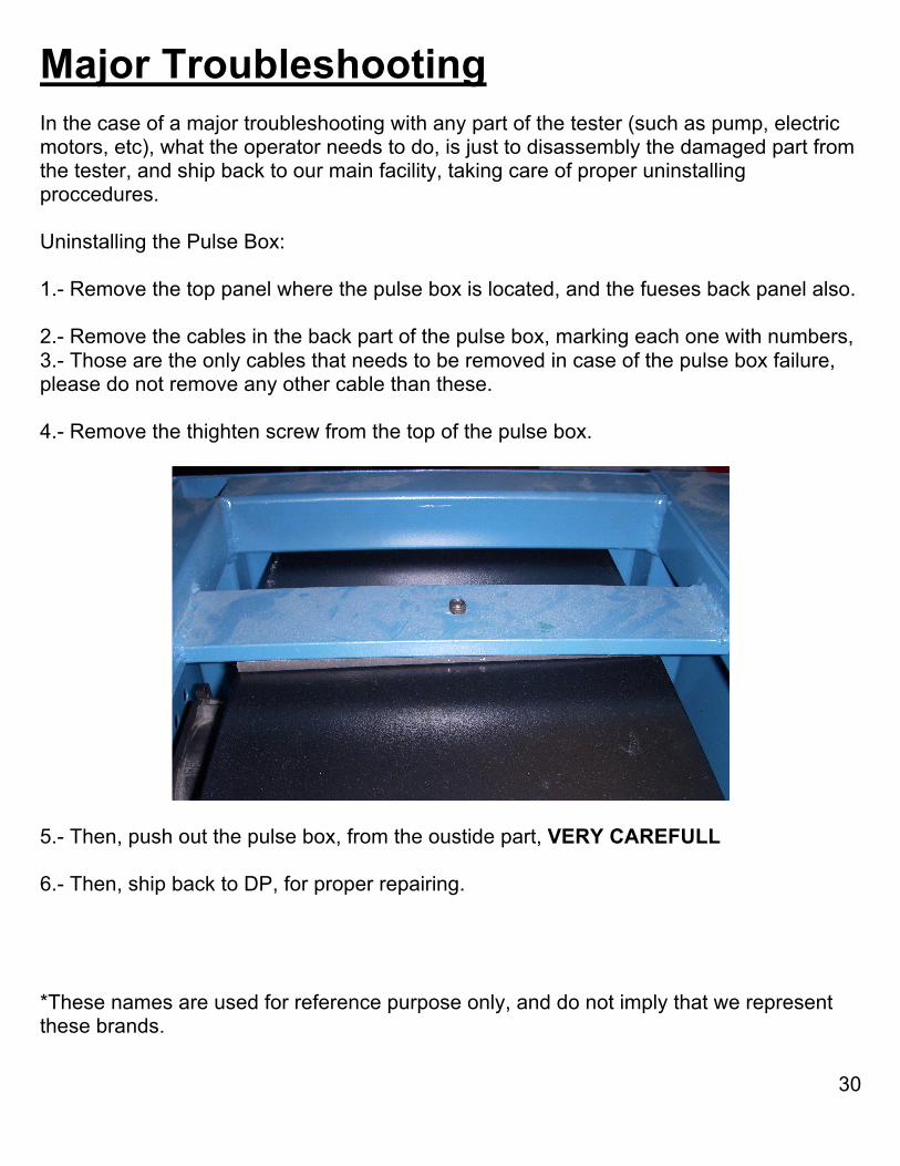
Major Troubleshooting In the case of a major troubleshooting with any part of the tester (such as pump, electric motors, etc), what the operator needs to do, is just to disassembly the damaged part from the tester, and ship back to our main facility, taking care of proper uninstalling proccedures. Uninstalling the Pulse Box: 1.- Remove the top panel where the pulse box is located, and the fueses back panel also. 2.- Remove the cables in the back part of the pulse box, marking each one with numbers, 3.- Those are the only cables that needs to be removed in case of the pulse box failure, please do not remove any other cable than these. 4.- Remove the thighten screw from the top of the pulse box.
5.- Then, push out the pulse box, from the oustide part, VERY CAREFULL 6.- Then, ship back to DP, for proper repairing.
*These names are used for reference purpose only, and do not imply that we represent these brands.

DIESEL PARTS OF AMERICA 13150 Leadwell Street, N. Hollywood, California, 91605 U.S.A.
31
NOTES