57-2556 installation instructions 11. lift the throttle body from the intake manifold and disconnect...
TRANSCRIPT
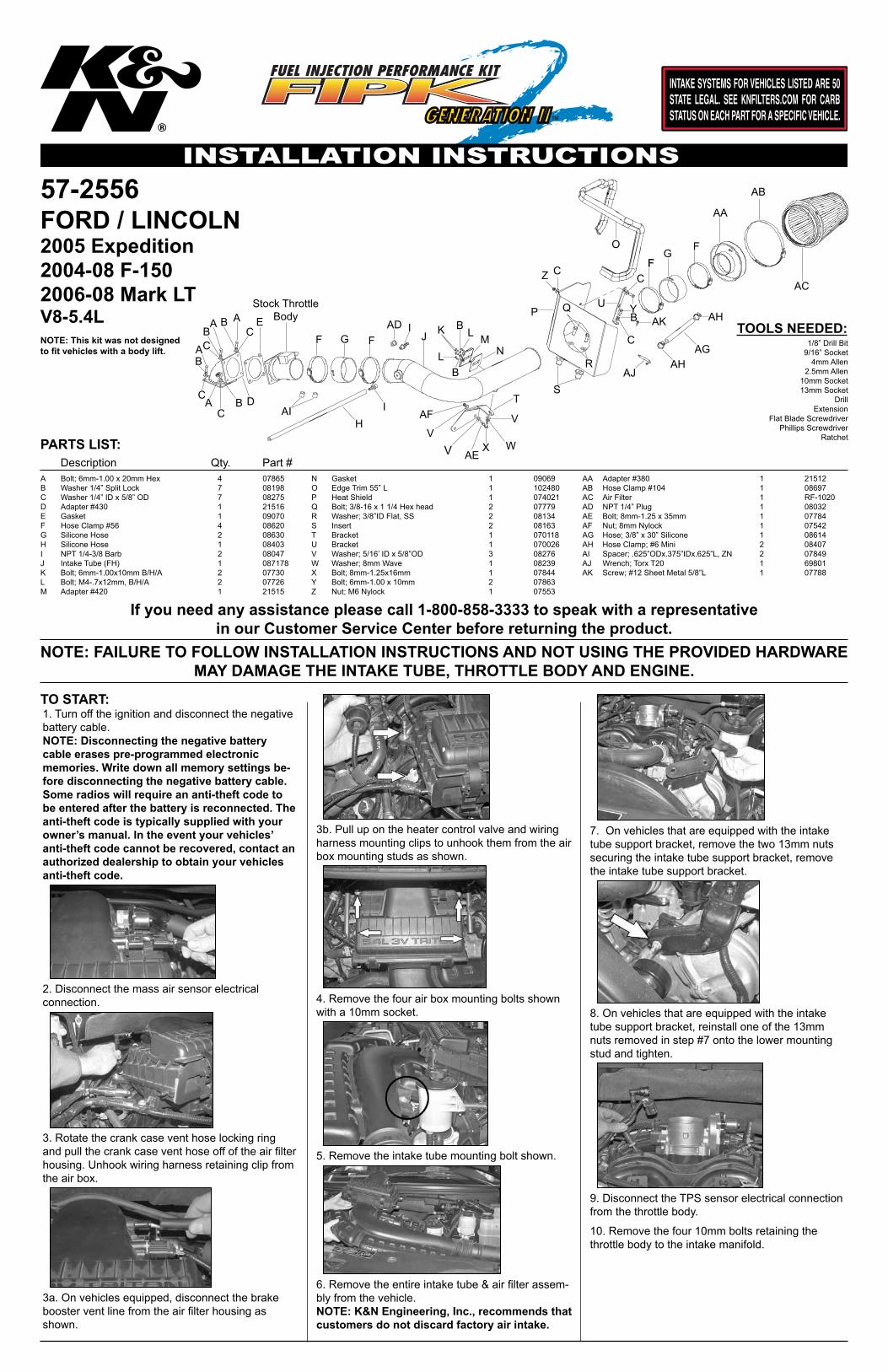
57-2556
TOOLS NEEDED:
PARTS LIST: Description Qty. Part #
NOTE: This kit was not designed to fit vehicles with a body lift.
TO START:
FORD / LINCOLN2005 Expedition2004-08 F-1502006-08 Mark LTV8-5.4L
1/8” Drill Bit9/16” Socket
4mm Allen2.5mm Allen
10mm Socket13mm Socket
DrillExtension
Flat Blade ScrewdriverPhillips Screwdriver
Ratchet
A Bolt; 6mm-1.00 x 20mm Hex 4 07865B Washer 1/4” Split Lock 7 08198C Washer 1/4” ID x 5/8” OD 7 08275D Adapter #430 1 21516E Gasket 1 09070F Hose Clamp #56 4 08620G Silicone Hose 2 08630H Silicone Hose 1 08403I NPT 1/4-3/8 Barb 2 08047J Intake Tube (FH) 1 087178K Bolt; 6mm-1.00x10mm B/H/A 2 07730L Bolt; M4-.7x12mm, B/H/A 2 07726M Adapter #420 1 21515
N Gasket 1 09069O Edge Trim 55” L 1 102480P Heat Shield 1 074021Q Bolt; 3/8-16 x 1 1/4 Hex head 2 07779R Washer; 3/8”ID Flat, SS 2 08134S Insert 2 08163T Bracket 1 070118U Bracket 1 070026V Washer; 5/16’ ID x 5/8”OD 3 08276W Washer; 8mm Wave 1 08239X Bolt; 8mm-1.25x16mm 1 07844Y Bolt; 6mm-1.00 x 10mm 2 07863Z Nut; M6 Nylock 1 07553
AA Adapter #380 1 21512AB Hose Clamp #104 1 08697AC Air Filter 1 RF-1020AD NPT 1/4” Plug 1 08032AE Bolt; 8mm-1.25 x 35mm 1 07784AF Nut; 8mm Nylock 1 07542AG Hose; 3/8” x 30” Silicone 1 08614AH Hose Clamp; #6 Mini 2 08407AI Spacer; .625”ODx.375”IDx.625”L, ZN 2 07849AJ Wrench; Torx T20 1 69801AK Screw; #12 Sheet Metal 5/8”L 1 07788
2. Disconnect the mass air sensor electricalconnection.
3. Rotate the crank case vent hose locking ring and pull the crank case vent hose off of the air filter housing. Unhook wiring harness retaining clip from the air box.
3a. On vehicles equipped, disconnect the brake booster vent line from the air filter housing as shown.
3b. Pull up on the heater control valve and wiring harness mounting clips to unhook them from the air box mounting studs as shown.
4. Remove the four air box mounting bolts shown with a 10mm socket.
6. Remove the entire intake tube & air filter assem-bly from the vehicle.NOTE: K&N Engineering, Inc., recommends that customers do not discard factory air intake.
7. On vehicles that are equipped with the intake tube support bracket, remove the two 13mm nuts securing the intake tube support bracket, remove the intake tube support bracket.
8. On vehicles that are equipped with the intake tube support bracket, reinstall one of the 13mm nuts removed in step #7 onto the lower mounting stud and tighten.
5. Remove the intake tube mounting bolt shown.
A
B
C D
EF G
HI
J K L MN
O
P Q
R
ST
U
VWX
Y
Z
AA
AB
AC
AD
AE
AF
AG
AH
AI
AJ
AKA A
A
B
B
B
CC
C
FI
L
B
B
V
V
C
C
B
FFG
AH
C
Stock Throttle Body
1. Turn off the ignition and disconnect the negative battery cable.NOTE: Disconnecting the negative battery cable erases pre-programmed electronic memories. Write down all memory settings be-fore disconnecting the negative battery cable. Some radios will require an anti-theft code to be entered after the battery is reconnected. The anti-theft code is typically supplied with your owner’s manual. In the event your vehicles’ anti-theft code cannot be recovered, contact an authorized dealership to obtain your vehicles anti-theft code.
9. Disconnect the TPS sensor electrical connection from the throttle body.
10. Remove the four 10mm bolts retaining the throttle body to the intake manifold.
NOTE: FAILURE TO FOLLOW INSTALLATION INSTRUCTIONS AND NOT USING THE PROVIDED HARDWARE MAY DAMAGE THE INTAKE TUBE, THROTTLE BODY AND ENGINE.
If you need any assistance please call 1-800-858-3333 to speak with a representative in our Customer Service Center before returning the product.
INSTALLATION INSTRUCTIONSContinued
11. Lift the throttle body from the intake manifold and disconnect throttle body motor electrical con-nection.NOTE: Use caution to avoid dropping debris down the intake manifold throat.
12. Using the bolts removed in step #10, secure the throttle body to the K&N® throttle body adapter with the gasket as shown.
13. Install the throttle body assembly onto the intake manifold with the hardware provided as shown.
14. Reconnect the throttle body motor and the TPS electrical connection.
15. Install the “L” bracket (#070026) onto the heat-shield with the provided hardware as shown.
16. Install the edge trim onto the heatshield as shown.NOTE: Some trimming of the edge trim may be necessary.
17. Install the provided nut inserts into the air box mounting holes as shown.
17a. Loosen the coolant recovery hose, hose clamps, and then remove the factory recovery hose shown. Be sure to catch any coolant, which flows out of the radiator during hose removal.NOTE: Be sure to let the engine cool complete-ly before removing the overflow hose or hot coolant will escape from the radiator and injury or damage may result.
17b. Install the supplied coolant recovery hose and secure with the provided hose clamps.NOTE: Be sure to replace the coolant that was recovered during hose removal by replenishing it in the coolant recovery tank.
18. Install the heatshield as shown and secure with the provided hardware.NOTE: Due to manufacture inconsistencies, some vehicles may not be equipped with the threaded hole in the factory filter mounting plate. It will be necessary to drill a 1/8” hole in the air filter mounting plate and attach the heat shield bracket with the provided sheet metal screw.
19. Remove the two screws that secure the mass air sensor to the air box with the provided wrench, then remove the mass air sensor.
20. Install the provided gasket onto the K&N® mass air adapter as shown; sticky side down.
21. Install the mass air sensor into the K&N® mass air adapter as shown and secure with the provided hardware.
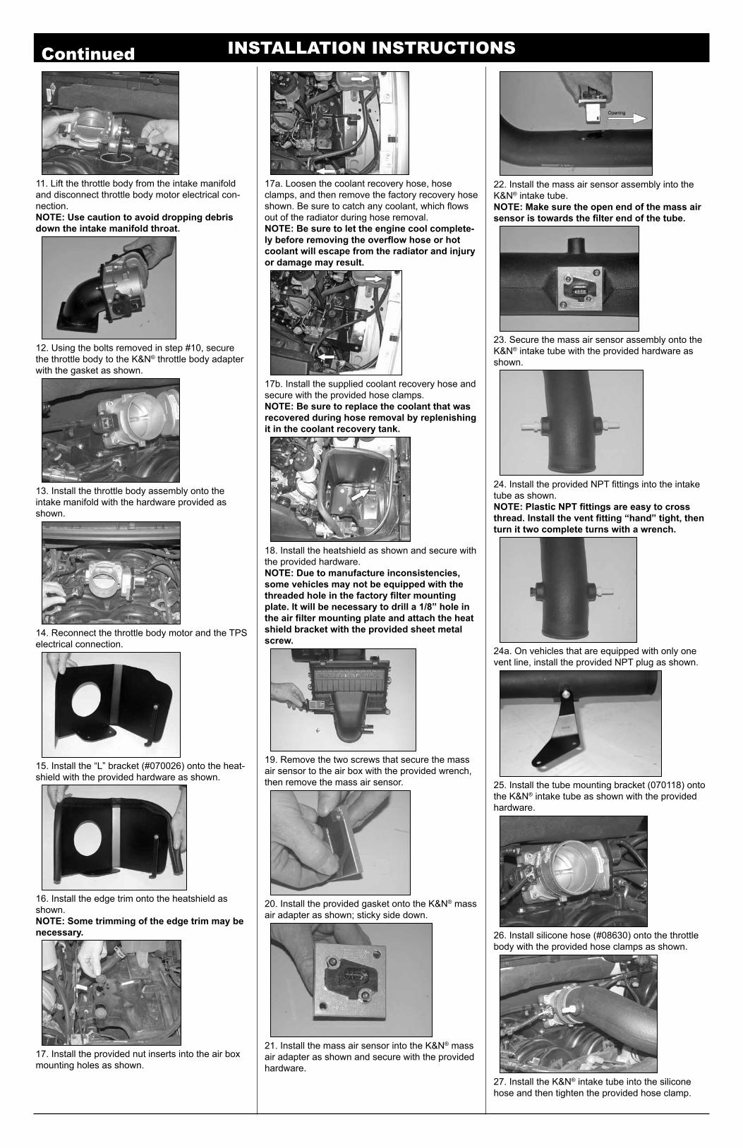
22. Install the mass air sensor assembly into the K&N® intake tube.NOTE: Make sure the open end of the mass air sensor is towards the filter end of the tube.
23. Secure the mass air sensor assembly onto the K&N® intake tube with the provided hardware as shown.
24. Install the provided NPT fittings into the intake tube as shown.NOTE: Plastic NPT fittings are easy to cross thread. Install the vent fitting “hand” tight, then turn it two complete turns with a wrench.
25. Install the tube mounting bracket (070118) onto the K&N® intake tube as shown with the provided hardware.
26. Install silicone hose (#08630) onto the throttle body with the provided hose clamps as shown.
24a. On vehicles that are equipped with only one vent line, install the provided NPT plug as shown.
27. Install the K&N® intake tube into the silicone hose and then tighten the provided hose clamp.
INSTALLATION INSTRUCTIONSContinued
1. Start the engine with the transmission in neutral or park, and the parking brake engaged. Listen for air leaks or odd noises. For air leaks secure hoses and connections. For odd noises, find cause and repair before proceeding. This kit will function iden-tically to the factory system except for being louder and much more responsive.
2. Test drive the vehicle. Listen for odd noises or rattles and fix as necessary.
3. If road test is fine, you can now enjoy the added power and performance from your kit.
4. K&N Engineering, Inc., requires cleaning the intake system’s air filter element every 100,000miles. When used in dusty or off-road environ-ments, our filters will require cleaning moreoften. We recommend that you visually inspect your filter once every 25,000 miles to determine if the screen is still visible. When the screen is no longer visible some place on the filter element, it is time to clean it. To clean and re-oil, purchase our filter Recharger® service kit, part number 99-5050 or 99-5000 and follow the easy instructions.
ROAD TESTING:
37. It will be necessary for all K&N® high flow intake systems to be checked periodically for realignment, clearance and tightening of all connections. Failure to follow the above instructions or proper mainte-nance may void warranty.
35. Reconnect the vehicle’s negative battery cable. Double check to make sure everything is tight and properly positioned before starting the vehicle.
* FREE K&N® decal To register your warranty, please see us online at knfilters.com/register. FREE K&N® decal *• 1455 CITRUS ST., P.O. BOX 1329, RIVERSIDE, CA., U.S.A. 92502 • TECH SERVICE 800-858-3333 • FAX 951-826-4001
• e-mail: [email protected]® • WWW: http://www.knfilters.com®
36. The C.A.R.B. exemption sticker, (attached), must be visible under the hood, so the emissions inspector can see it when the vehicle is required to be tested for emissions. California requires testing every two years, other states may vary.
170060X9/23/16
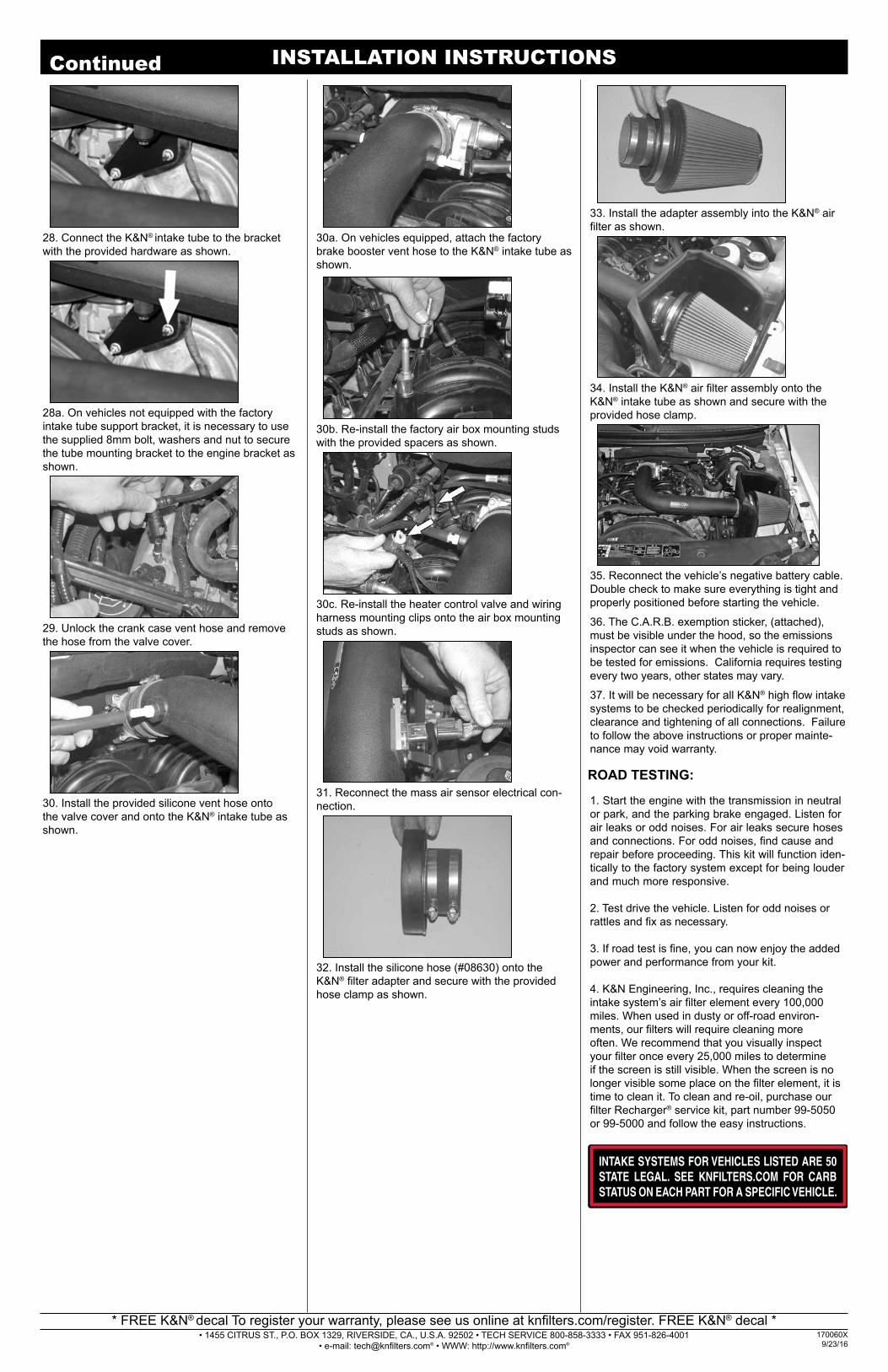
28. Connect the K&N® intake tube to the bracket with the provided hardware as shown.
28a. On vehicles not equipped with the factory intake tube support bracket, it is necessary to use the supplied 8mm bolt, washers and nut to secure the tube mounting bracket to the engine bracket as shown.
29. Unlock the crank case vent hose and remove the hose from the valve cover.
30. Install the provided silicone vent hose onto the valve cover and onto the K&N® intake tube as shown.
30a. On vehicles equipped, attach the factory brake booster vent hose to the K&N® intake tube as shown.
30b. Re-install the factory air box mounting studs with the provided spacers as shown.
30c. Re-install the heater control valve and wiring harness mounting clips onto the air box mounting studs as shown.
31. Reconnect the mass air sensor electrical con-nection.
32. Install the silicone hose (#08630) onto the K&N® filter adapter and secure with the provided hose clamp as shown.
33. Install the adapter assembly into the K&N® air filter as shown.
34. Install the K&N® air filter assembly onto the K&N® intake tube as shown and secure with the provided hose clamp.