5g-flow: a unified multi-rat ran architecture for beyond 5g
TRANSCRIPT
5G-Flow: A Unified Multi-RAT RAN Architecture for Beyond 5G Networks
Meghna Khaturiaa, Pranav Jhaa, Abhay Karandikara,b
aDepartment of Electrical Engineering, Indian Institute of Technology Bombay, Mumbai, IndiabDirector, Indian Institute of Technology Kanpur, India
Abstract
Convergence of multiple access technologies is one of the key enablers in providing diverse set of services to the Fifth Generation(5G) users. Though 3rd Generation Partnership Project (3GPP) 5G standard defines a common core supporting multiple RadioAccess Technologies (RATs), Radio Access Network (RAN) level decisions are taken separately across individual RATs as theexisting 5G architecture lacks a unified control and management framework for a multi-RAT network. A unified access networkis likely to utilize RAN resources more efficiently and provide an improved performance. In order to achieve a unified Multi-RATRAN, we supplement the existing 3GPP 5G RAN architecture with OpenFlow. We refer to the proposed architecture as 5G-Flow.The proposed architecture can be viewed as a step towards further evolution of mobile networks beyond 5G. With minimal changesin the 3GPP 5G RAN and none in the core network, we are able to realize a unified and integrated multi-access 5G-Flow RAN. Wesimplify the existing 5G RAN by replacing RAN nodes with OpenFlow switches and a software-defined controller. The proposedarchitecture also allows us to completely decouple User Equipment’s (UE’s) communication with Core Network (CN) from itscommunication with RAN enabling a UE to use any RAT to connect to any CN (say, use 5G New Radio access to connect to 4GCN, which is not possible in the 3GPP architecture) or to directly connect to Internet from RAN without going via the CN. Wehave developed an evaluation platform to compare the performance of our proposal with the standard 3GPP architecture. Resultsdemonstrate significant gains in the network performance of 5G-Flow RAN over the existing 3GPP 5G network.
1. Introduction
The Fifth Generation (5G) cellular standard envisions to sup-port various use-cases, i.e., enhanced mobile broadband, ultra-reliable low latency communications, and massive machine-type communications [1]. These new requirements have ledto several innovations and a redesign of the cellular network aspart of 3rd Generation Partnership Project (3GPP) 5G standard-ization, such as service-based architecture, virtualized networkfunctions, control and user planes separation, and network slic-ing. One of the major advancements is the unification of mul-tiple access technologies in 5G Core Network (5GC), which isan essential step towards enhancing network efficiency. The3GPP 5G access network incorporates heterogeneous accesstechnologies, i.e., 3GPP access (e.g., New Radio(NR) basednext-generation NodeB (gNB), and Long Term Evolution(LTE)based evolved NodeB (eNB)) and non-3GPP access (e.g., Wi-Fiand wireline access). Towards this, 5G standard has introduceda common interface between 5GC and 5G Radio Access Net-work (RAN), to integrate multiple access networks at the corenetwork. However, there are certain gaps in the current 3GPP5G architecture that we discuss next.
Even though 5GC exposes a common interface towards RANirrespective of the Radio Access Technology (RAT) being used,i.e., N2 interface for control signaling and N3 interface for userdata transfer, 5G standard defines different inter-working enti-ties (between RAN and 5GC) for different RATs [1]. For in-stance, a network entity called Non-3GPP Inter-Working Func-tion (N3IWF) has been introduced for untrusted non-3GPP ac-cess (e.g., Wi-Fi), which incorporates N2/N3 protocol stack. Incontrast, for 5G NR based access, N2/N3 protocol stack is in-
corporated within gNB, a new node providing NR data and con-trol planes protocol terminations towards the UE. RAT-specificinter-working entities and associated interfaces result in a com-plex RAN architecture. Complexity also increases at 5GC, asregistration state per RAT is maintained at 5GC if a User Equip-ment (UE) is connected to more than one RAT. 5GC also con-trols traffic steering and switching across RATs for UEs con-currently connected to multiple RATs [1, 2]. However, 5GCmay be unable to optimally manage the traffic across RATs asit has limited RAN level information. Another feature of the3GPP 5G architecture is the tight coupling between RAN andCN which results in an inflexible architecture. For instance, it isnot possible to use 5G NR based gNB with Fourth Generation(4G) Core Network (CN) in the 3GPP 5G network. The cur-rent 5G Non-Standalone (NSA) architecture can be viewed asan implication of this feature, wherein 4G eNB has to deployedalongside gNB to utilize the existing 4G CN infrastructure.
Taking into consideration the above-mentioned limitations,we re-architect the 3GPP 5G RAN to realize a unified, in-tegrated, software-defined multi-RAT RAN using OpenFlowProtocol [3]. We refer to the proposed RAN architecture as5G-Flow. It employs OpenFlow switches (network switchesbased on OpenFlow protocol) and a light-weight OpenFlowcontroller (also called 5G-Flow controller). Unlike 3GPP 5GRAN design, we propose a unified inter-working interface to-wards 5GC. To realize this entity, we split the protocol stack atRAN nodes (i.e., gNB, N3IWF, etc.), separating the radio proto-col stack from the N2/N3 protocol stack. We bring together theradio protocol stack of different RATs and N2/N3 protocol stackas different interfaces of an OpenFlow switch in the multi-RAT
Preprint submitted to Journal of Computer Networks June 6, 2021
network. Similarly, OpenFlow switch at UE decouples Non-Access Stratum (NAS) and IP layers from the underlying ra-dio interface stack at the UE. In essence, the proposed protocolsplit at UE and RAN nodes along with the usage of OpenFlowswitches (to connect the protocol stacks of these entities) de-couples UE’s communication with CN from its communicationwith RAN. This feature allows a UE to flexibly use any radiointerface to connect to any CN. For instance, a UE can use 5GNR based radio interface to connect to 4G CN or directly con-nect to Internet bypassing the CN, which is not possible in theexisting 3GPP 5G network. We summarize some of the novelcontributions of the work presented in this paper —
• One of the key innovations is to integrate multiple RATs andrealize a unified inter-working interface towards 5GC using anOpenFlow switch.• A light-weight 5G-Flow controller enables RAN level man-agement of downlink as well as uplink dataflows, in turn, uti-lizing the multi-RAT resources efficiently. Existing OpenFlowabstractions, such as, logical ports and flows are used to controlthe user traffic flowing through the OpenFlow interfaces.• 5G-Flow controller manages multiple RATs through Open-Flow protocol messages. The interfaces at OpenFlow switchesare responsible for translating these messages to interface-specific action messages.• UE’s connectivity to RAN is fully decoupled from its con-nectivity to CN. This brings immense flexibility and enables aUE to interface with 5GC, 4G CN, Internet, or any other datanetwork via any 4G/5G/Wi-Fi based RAN.• Decoupling of radio and CN protocol stacks at RAN allowsus to support the 5G non-standalone architecture in a simplifiedmanner wherein a UE need not be dual connected to gNB andeNB. It can connect to 4G CN via gNB.• We have developed a 5G simulator with Multi-RAT support(for NR and Wi-Fi) since an open source 5G simulator is not yetavailable. The source code of the 5G multi-RAT simulator hasbeen released under MIT License for the benefit of the researchcommunity.• We have also designed a heuristic algorithms for data flowmanagement for performance evaluation of the proposed 5GFlow network.
As would become clear later, we do not propose to replacethe existing protocols and interfaces defined by the 3GPP 5Gstandards. Instead, the proposal intends to supplement the ex-isting 5G standards to achieve a unified multi-RAT RAN bystandardizing those interfaces which are typically deemed pro-prietary by 3GPP. The proposal requires minimal changes inRAN and none in CN.
The rest of the paper is organized as follows. In Section IIand III, we discuss the literature and background related to theproposed work. In Section IV and V, we discuss the proposednetwork architecture and its working. We discuss the perfor-mance analysis and applications of our proposal in Section VIand VII, respectively. We conclude our work in Section VIII.
2. Related Work
Several efforts in the literature deal with the applicationof SDN in cellular networks to make the network more pro-grammable and in turn, more manageable. Research workssuch as SoftRAN [4], SoftMobile [5], FlexRAN [6], SoftNet [7]and Software-Defined Wireless Network (SDWN) [8] aim atmaking RAN more programmable, flexible and specifically, useresources efficiently. SoftAir [9] uses SDN paradigm and hard-ware abstraction to enable a scalable network architecture for5G. SoftCell [10] aims to introduce scalability and flexibilityin cellular core networks. To support rapid protocol evolution,OpenRadio uses SDN paradigm to decouple the wireless pro-tocol into processing and decision planes and provide a pro-grammable interface between the two planes [11]. However,none of the above works consider multi-RAT integration in theaccess network.
We now discuss some research works that propose SDNbased network architecture to manage heterogeneous RATs. In[12], the authors introduce a virtual MAC layer at networknodes and users in order to manage heterogeneous RATs in atechnology independent manner. In [13, 14], the authors havedeveloped a prototype that augments WiMAX and Wi-Fi APswith OpenFlow. OpenRAN [15] uses virtualization to design asoftware-defined multi-access RAN. However, extension of theproposed concept in [12, 13, 14, 15] for 3GPP 4G/5G networkis not straightforward. 5G-EmPOWER [16] proposes an SDNbased framework to manage heterogeneous access networks in-cluding Wi-Fi and 4G. However, we do not intend to propose anew framework but suggest enhancements to the existing 3GPP5G architecture to realise a multi-RAT RAN.
The authors in [17] propose an end-to-end SDN based archi-tecture for a mobile network with a controller managing bothaccess and CN data plane elements by providing an abstractview of the underlying network resources to the controller.In [18], the authors propose a multi-RAT architecture and definea unified and open interface between the controller and multi-RAT data plane. In [19], the authors propose a convergencesub-layer over layer 2 of multiple RATs in order to tightly inte-grate them. While [17, 18, 19] modify the radio protocol stackfor RAT integration, the radio stack of different RATs in 5G-Flow RAN remains unchanged. To integrate LTE with Wi-Fi,LTE-Wireless Local Area Network Aggregation (LWA) mech-anism has been proposed by 3GPP [20, 21]. LWA proposes anemulation layer over Wi-Fi AP that encapsulates LTE packetsin Wi-Fi MAC frame.
To the best of our knowledge, none of the above works pro-pose an integrated Multi-RAT RAN with a unified CN inter-working entity. Moreover, the usage of OpenFlow to achievethe same, with minimal modifications in the existing 3GPP pro-tocol stacks and interfaces, has also not been discussed in theliterature. Another novelty of our proposal is the decouplingof RAN from the CN and treat UE-CN communication as anoverlay communication over the UE-RAN (radio) link, whichallows a UE to flexibly use any radio link (NR/LTE/Wi-Fi) toconnect to any CN (5G/4G) or even to Internet directly. Thisalso has not been discussed in the literature as yet.
2
3. Background
In this section, we discuss OpenFlow protocol and some ba-sic 3GPP 5G terminologies which form the basis of our discus-sion ahead.
OpenFlow Protocol: OpenFlow is a protocol used by anSDN Controller to manage the forwarding plane of a net-work. [3]. An OpenFlow compliant network consists of a log-ically centralized OpenFlow controller (SDN controller) andmultiple OpenFlow switches (forwarding plane). An OpenFlowswitch supports an OpenFlow client, which communicates withan OpenFlow controller through a secure channel. The con-troller manages the flow tables present in OpenFlow switchesusing OpenFlow protocol. A flow-table comprises several flow-entries that match on a packet based on match-fields such as IPaddress or TCP port number. Based on the flow-entry, an actionis taken (e.g. forward or drop) on the matched packet.
An OpenFlow switch supports physical and logical ports. Aphysical port corresponds to a hardware interface on an Open-Flow switch. A logical port does not directly correspond to ahardware interface, but it is an abstraction of a physical port.It can be used to implement processing of packets in Open-Flow switch. In our proposal, the complex protocol process-ing is done as part of the logical port in the OpenFlow switch.OpenFlow-Configuration (OF-Config) protocol, a complemen-tary protocol based on Network Configuration Protocol (NET-CONF) [22], helps in configuration and management of Open-Flow switches [23]. OF-Config is responsible for associationbetween a controller and an OpenFlow switch and configura-tion of physical and logical ports. To inform the OpenFlowcontroller about various events at OpenFlow switches such aslink failures or configuration changes, OpenFlow NotificationsFramework provides a method to subscribe to asynchronousmessages based on predefined events [24].
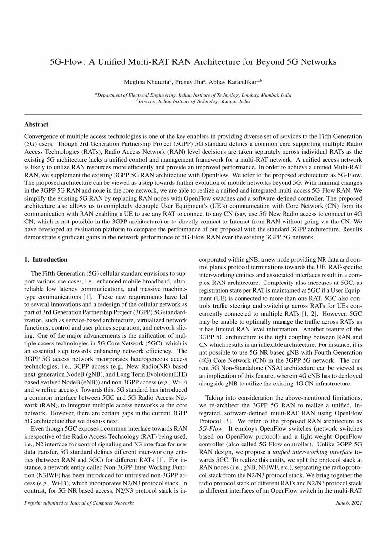
5G Primer: Fig. 1 illustrates the protocol stack of UE andgNB as defined in the 3GPP 5G standard [1]. gNB consistsof a Centralized Unit (CU) and one or many Distributed Units(DUs). gNB-CU can be further divided into control plane(gNB-CU-CP) and user plane (gNB-CU-UP) components. UEand gNB both have Radio Resource Control (RRC) layer thatfacilitates control plane interaction between the two entities.RRC also helps in radio connection establishment and release,mobility management, and setting up of radio bearers. ServiceData Adaptation Protocol (SDAP) layer, along with the under-lying protocol stack, at UE and gNB, is responsible for userplane data transfer over the radio interface along with Quality ofService (QoS) handling of dataflows. NAS Layer present at UEis responsible for non-radio related signaling between UE and5GC. 5G RAN communicates with 5GC through N2 and N3 in-terfaces. Next-Generation Application Protocol (NGAP) layer,together with the underlying protocol stack (N2 interface), is re-sponsible for all signaling (control) message exchange betweenRAN and Access and Mobility Management Function (AMF)in 5GC. Data packets between RAN and User Plane Function(UPF) are exchanged over N3 interface using GPRS TunnelingProtocol (GTP) and the underlying UDP/IP protocol stack.
The NGAP-RRC and SDAP-GTP protocol interfaces in gNB
gNB
UEDataControl
DU
CU-UPCU-CP
PDCP-C
RLC
MAC
PHY
RRC SDAP
PDCP-U
PDCP
RLC
MAC
PHY
RRC SDAP
PDCP
RLC
MAC
PHY
SCTP
IP
L2/L1
NGAP
NAS IP
UDP
L2/L1
GTP
Relay
IP
Relay
N3 (Towards
UPF)
N2 (Towards
AMF)
Proprietary Interfaces
F1-C F1-U
Figure 1: 3GPP 5G gNB and UE Protocol Stack
are tightly coupled with each other and utilize proprietary ven-dor specific communication mechanism, as shown in Fig. 1.Though not shown in the figure, other 5G RAN nodes such asN3IWF also use proprietary interfaces for communication be-tween their radio and CN stacks. The tight coupling between ra-dio and CN protocol stacks on RAN nodes is one of the reasonsbehind RAT specific Inter-working functions in 5G. Similarly,higher layers (NAS and IP Layers) at UE are tightly coupledto the underlying radio protocol stack, leading to close inter-working between RAN and CN.
When a UE wants to connect with a data network, such asInternet, the 5G network establishes an end-to-end tunnel be-tween UE and UPF (i.e., a Protocol Data Unit (PDU) Session).Additionally, a unique signaling link between UE and 5G Net-work (both at 5GC and RAN) is also established to exchangecontrol messages between the UE and the 5G network. Theend-to-end data tunnel (PDU Session) takes the form of a DataRadio Bearer (DRB) at the air interface, while the signalinglink takes the form of a Signaling Radio Bearer (SRB). Radiobearers are essentially layer 2 tunnels. Between gNB and 5GC(AMF+SMF), UE specific signaling messages (NAS messages)are exchanged through a (per UE) unique association over N2interface, whereas a PDU Session takes the form of a GTP tun-nel between gNB and 5GC (UPF).
In 3GPP 5G network, different unique identifiers are used toidentify UE specific signaling association and data tunnels overdifferent interfaces. For example, to uniquely identify UE overN2 interface, gNB uses RAN UE NGAP ID, whereas AMF usesAMF UE NGAP ID. Similarly, UE specific data tunnels areuniquely identified via GTP Tunnel End-point Indicator (TEID)on N3 interface.
4. 5G-Flow RAN Architecture
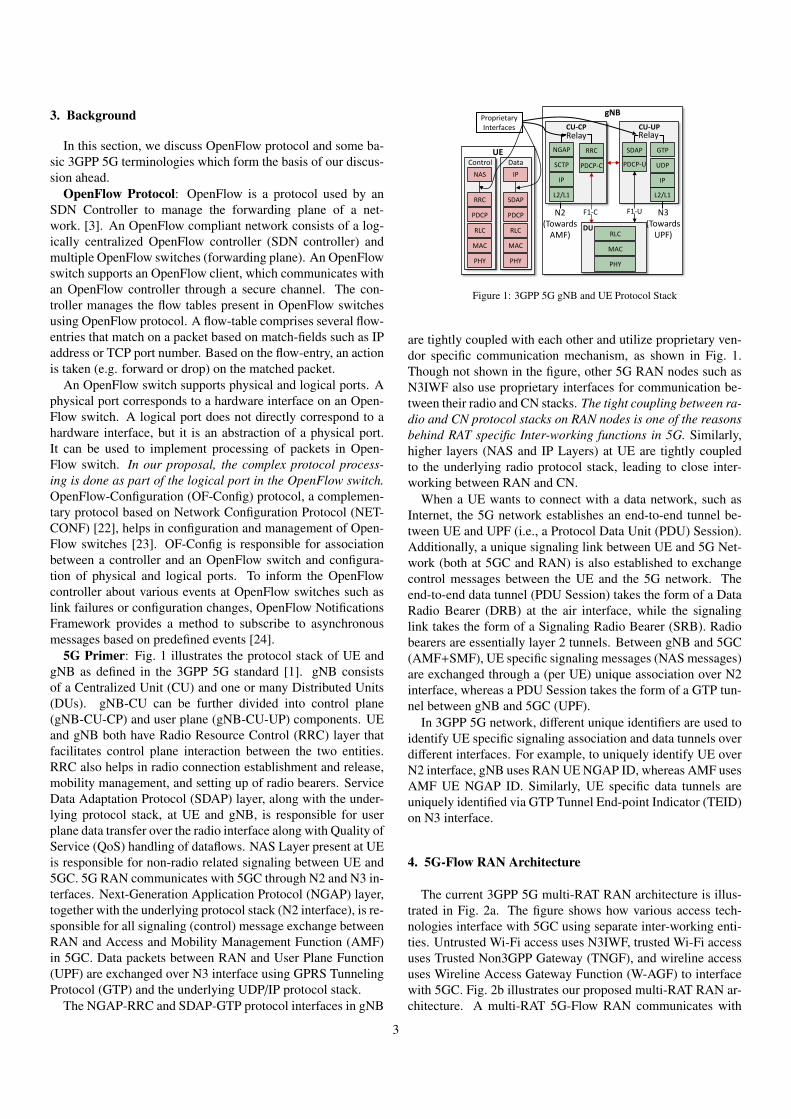
The current 3GPP 5G multi-RAT RAN architecture is illus-trated in Fig. 2a. The figure shows how various access tech-nologies interface with 5GC using separate inter-working enti-ties. Untrusted Wi-Fi access uses N3IWF, trusted Wi-Fi accessuses Trusted Non3GPP Gateway (TNGF), and wireline accessuses Wireline Access Gateway Function (W-AGF) to interfacewith 5GC. Fig. 2b illustrates our proposed multi-RAT RAN ar-chitecture. A multi-RAT 5G-Flow RAN communicates with
3

5G Core Network
UPFAMF
Untrusted Wi-Fi AP
TrustedWi-Fi AP
WirelineAccess
3GPP 5G Multi-RAT Network
gNB NG-eNB
N3IWF TNGF W-AGF
UE
Control
Data
Control + Data
(a) 3GPP 5G multi-access RAN architecture
5G Core Network
UPFAMF
5G-Flow Multi-RAT Network
gNB Radio Interface
eNB Radio Interface
5G-Flow Controller
External Network Interface
Untrusted Wi-Fi AP
Trusted Wi-Fi AP
WirelineAccess
External Data Network
Control
Data
Control + Data UE
Core Network Interface
(b) Proposed 5G-Flow RAN Architecture
Figure 2: Conceptual diagram for 5G-Flow RAN architecture and its comparison with the current 3GPP 5G RAN
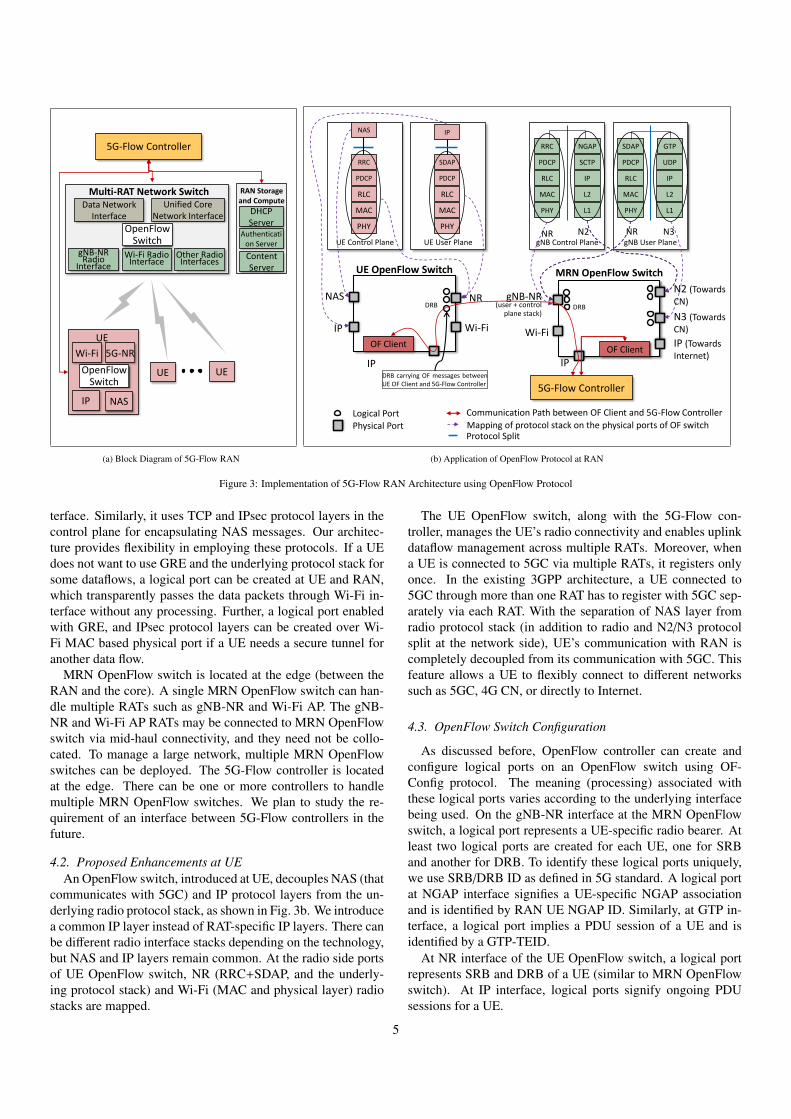
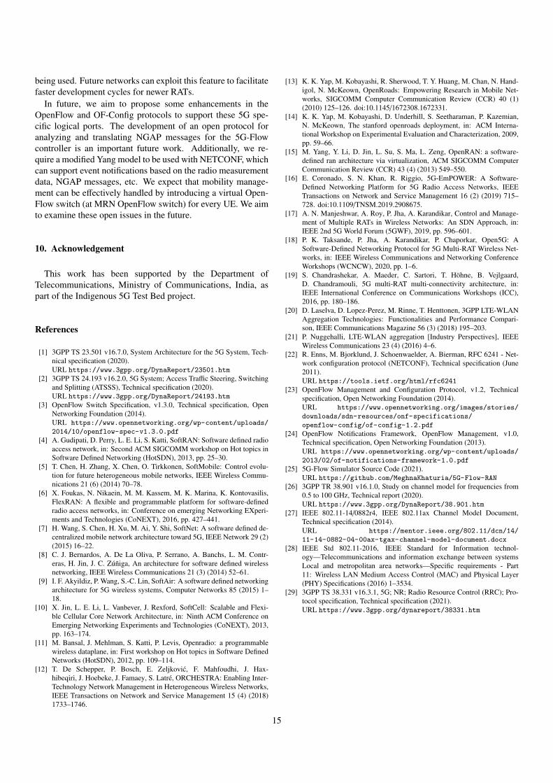
5GC through a unified inter-working interface instead of sepa-rate inter-working functions. Additionally, we aim to enable aflexible interface between RAN and CN, such that any RANcan connect with any cellular CN or Internet directly. Thesoftware-defined 5G-Flow controller acts as a multi-RAT RANcontroller that manages the unified inter-working entity anddataflows across multiple RATs in RAN. Since the controllerhas access to RAN-level information such as traffic load and ra-dio channel conditions, it can efficiently manage the downlinkdataflows across RATs. As shown in Fig. 2b, the controller alsocontrols the UE, which enables uplink dataflow management ina multi-RAT RAN. The figure illustrates communication linkbetween UE and controller via gNB-NR (in-band link). How-ever, any RAT can be used for UE-controller communication.To realize the proposed 5G-Flow RAN1 architecture, we ap-ply the OpenFlow concepts [3]. We envision 5G RAN as anOpenFlow network comprising a 5G-Flow controller (asOpen-Flowcontroller) andOpenFlowswitches that are instantiated onthe network side and the associated UEs, as shown in Fig. 3a.We discuss the enhancements to the current 3GPP 5G archi-tecture to realize the 5G-Flow network in the remainder of thissection.
4.1. Proposed Multi-RAT Network
The existing 3GPP 5G RAN consists of various multi-RATnetwork nodes, including 3GPP access (e.g., gNB, eNB) andnon-3GPP access (e.g., Wi-Fi, N3IWF). To integrate multipleRATs in 5G-Flow RAN and enable a unified inter-working in-terface, we propose a protocol split between radio interface andN2/N3 protocol stack of RAN nodes. For 3GPP access nodessuch as gNB, split happens at the gNB node itself, whereas fornon-3GPP access, it is done at the inter-working function suchas N3IWF. To illustrate the protocol split, we take an exampleof gNB. As discussed previously, gNB consists of tightly cou-pled NR protocol stack (which interfaces with a UE) and N2/N3
1Although we discuss radio access technologies in the rest of the paper, thenetwork architecture is applicable to wireline technologies as well.
protocol stack (which interfaces with the 5GC). As shown inFig. 3b, we split gNB vertically and separate gNB-NR andN2/N3 protocol stack. We can similarly split N3IWF node.We now introduce an OpenFlow switch, referred to as Multi-RAT Network (MRN) OpenFlow switch, which is responsiblefor bridging radio and N2/N3 protocol stacks of multiple RATs.These protocol stacks form different interfaces (physical ports)of MRN OpenFlow switch. The 5G-Flow controller directsMRN OpenFlow switch to process the messages from differentradio interfaces and deliver them to N2/N3 stack towards 5GCand vice-versa. This way, the MRN OpenFlow switch alongwith the 5G-Flow controller replaces all RAT-specific entitiessuch as gNB, eNB, N3IWF, etc. and exposes a unified interfacetowards CN.
The MRN OpenFlow switch has physical ports both at theradio and the 5GC interface side, as shown in Fig. 3b. Boththe control plane (RRC and underlying protocol stack) and thedata plane (SDAP and underlying protocol stack) of gNB-NRradio interface map to one of the radio side ports of the Open-Flow switch. Similarly, Wi-Fi Media Access Control (MAC)and physical layer map to another port. NGAP and GTP proto-col layers (along with the underlying N2/N3 stack) map to thephysical ports on the 5GC side. The physical port, labeled as IP,interfaces with the external data network. As the radio interfacestack is decoupled from the N2/N3 protocol stack, OpenFlowswitch can steer the data traffic of a UE towards IP port, en-abling direct connectivity with Internet bypassing the CN. Aninterface towards 4G CN is not shown in the figure, but it can beeasily incorporated by adding S1-Mobility Management Entity(S1-MME) interface as a separate physical port in the proposedOpenFlow switch. This feature enables a UE with 4G compati-ble NAS layer to communicate with 4G CN via 5G RAN. Thisfeature is discussed in the detail in Section 8.1.
In Fig. 3b, we have mapped Wi-Fi MAC layer to the radioside port in MRN OpenFlow switch. However, the user planeof N3IWF uses additional protocol layers i.e., Generic Rout-ing Encapsulation (GRE) and IP Security (IPsec), for creatinga secure tunnel between UE and N3IWF over Wi-Fi radio in-
4
gNB-NR Radio
InterfaceWi-Fi Radio
Interface
OpenFlow Switch
5G-Flow Controller
Unified Core Network Interface
Data Network Interface
Multi-RAT Network Switch
UE UEOpenFlow Switch
5G-NR Wi-Fi
UE
IP
Other Radio Interfaces
NAS
DHCP Server
Content Server
RAN Storage and Compute
Authentication Server
(a) Block Diagram of 5G-Flow RAN
N2 (Towards CN)
IP (Towards Internet)
gNB-NR (user + control
plane stack)
Wi-Fi
OF Client
5G-Flow Controller
DRB
N3 (Towards CN)Wi-FiIP
IP
OF Client
DRBNAS
Physical PortLogical Port
UE OpenFlow Switch MRN OpenFlow Switch
Communication Path between OF Client and 5G-Flow Controller
NR
DRB carrying OF messages betweenUE OF Client and 5G-Flow Controller
UE Control Plane UE User Plane
PDCP
RLC
MAC
PHY
SDAP
PDCP
RLC
MAC
PHY
RRC
NAS IP
gNB Control Plane gNB User Plane
PDCP
RLC
MAC
PHY
UDP
IP
L2
L1
SDAP GTP
NR N3
PDCP
RLC
MAC
PHY
SCTP
IP
L2
L1
RRC NGAP
NR N2
IP
Mapping of protocol stack on the physical ports of OF switchProtocol Split
(b) Application of OpenFlow Protocol at RAN
Figure 3: Implementation of 5G-Flow RAN Architecture using OpenFlow Protocol
terface. Similarly, it uses TCP and IPsec protocol layers in thecontrol plane for encapsulating NAS messages. Our architec-ture provides flexibility in employing these protocols. If a UEdoes not want to use GRE and the underlying protocol stack forsome dataflows, a logical port can be created at UE and RAN,which transparently passes the data packets through Wi-Fi in-terface without any processing. Further, a logical port enabledwith GRE, and IPsec protocol layers can be created over Wi-Fi MAC based physical port if a UE needs a secure tunnel foranother data flow.
MRN OpenFlow switch is located at the edge (between theRAN and the core). A single MRN OpenFlow switch can han-dle multiple RATs such as gNB-NR and Wi-Fi AP. The gNB-NR and Wi-Fi AP RATs may be connected to MRN OpenFlowswitch via mid-haul connectivity, and they need not be collo-cated. To manage a large network, multiple MRN OpenFlowswitches can be deployed. The 5G-Flow controller is locatedat the edge. There can be one or more controllers to handlemultiple MRN OpenFlow switches. We plan to study the re-quirement of an interface between 5G-Flow controllers in thefuture.
4.2. Proposed Enhancements at UEAn OpenFlow switch, introduced at UE, decouples NAS (that
communicates with 5GC) and IP protocol layers from the un-derlying radio protocol stack, as shown in Fig. 3b. We introducea common IP layer instead of RAT-specific IP layers. There canbe different radio interface stacks depending on the technology,but NAS and IP layers remain common. At the radio side portsof UE OpenFlow switch, NR (RRC+SDAP, and the underly-ing protocol stack) and Wi-Fi (MAC and physical layer) radiostacks are mapped.
The UE OpenFlow switch, along with the 5G-Flow con-troller, manages the UE’s radio connectivity and enables uplinkdataflow management across multiple RATs. Moreover, whena UE is connected to 5GC via multiple RATs, it registers onlyonce. In the existing 3GPP architecture, a UE connected to5GC through more than one RAT has to register with 5GC sep-arately via each RAT. With the separation of NAS layer fromradio protocol stack (in addition to radio and N2/N3 protocolsplit at the network side), UE’s communication with RAN iscompletely decoupled from its communication with 5GC. Thisfeature allows a UE to flexibly connect to different networkssuch as 5GC, 4G CN, or directly to Internet.
4.3. OpenFlow Switch Configuration
As discussed before, OpenFlow controller can create andconfigure logical ports on an OpenFlow switch using OF-Config protocol. The meaning (processing) associated withthese logical ports varies according to the underlying interfacebeing used. On the gNB-NR interface at the MRN OpenFlowswitch, a logical port represents a UE-specific radio bearer. Atleast two logical ports are created for each UE, one for SRBand another for DRB. To identify these logical ports uniquely,we use SRB/DRB ID as defined in 5G standard. A logical portat NGAP interface signifies a UE-specific NGAP associationand is identified by RAN UE NGAP ID. Similarly, at GTP in-terface, a logical port implies a PDU session of a UE and isidentified by a GTP-TEID.
At NR interface of the UE OpenFlow switch, a logical portrepresents SRB and DRB of a UE (similar to MRN OpenFlowswitch). At IP interface, logical ports signify ongoing PDUsessions for a UE.
5
UE1 OpenFlow SwitchRule ActionIncoming NAS message at LP1 (SRB)
Forward to NAS
Incoming packet at NAS
Forward to LP1 (SRB)
Incoming data packet at LP2 (DRB)
Forward to IP
Incoming packet at IP Forward to LP2 (DRB)
Wi-FiIPOF Client
LP2NAS
UE1 OpenFlow Switch
NR LP1
IP (OF Client)
MRN OpenFlow Switch
MRN OpenFlow SwitchRule ActionIncoming NAS (UL) message at LP1 (through RRC on SRB)
Forward to LP5
Incoming NAS (DL) message at LP5 (through NGAP)
Forward to LP1
Incoming data packet (UL) at LP2 (DRB UE1)
Forward to LP7
Incoming data packet (DL) at LP7 (GTP UE1)
Forward to LP2
N2 (Towards CN)
IP (Towards Internet)
gNB-NR
Wi-Fi OF Client
LP3
N3 (Towards CN)
IP (OF Client)
LP2LP5LP6
LP8LP7
LP1
LP4
NA
SD
ata
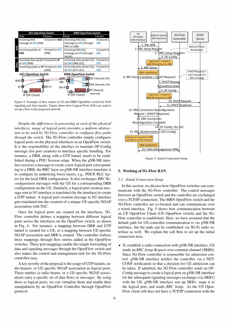
Figure 4: Example of flow entries at UE and MRN OpenFlow switch for NASsignaling and data transfer. Figure shows how Logical Ports (LPs) are used toset up a flow in the proposed network.
Despite the differences in processing at each of the physicalinterfaces, usage of logical ports provides a uniform abstrac-tion to be used by 5G-Flow controller to configure flow pathsthrough the switch. The 5G-Flow controller simply configureslogical ports on the physical interfaces in an OpenFlow switch.It is the responsibility of the interface to translate OF-Configmessage (for port creation) to interface specific handling. Forinstance, a DRB, along with a GTP tunnel, needs to be estab-lished during a PDU Session setup. When the gNB-NR inter-face receives a message to create a new logical port correspond-ing to a DRB, the RRC layer on gNB-NR interface translates itto configure its underlying lower layers, e.g., PDCP, RLC lay-ers for the local DRB configuration. It also exchanges RRC Re-configuration messages with the UE for a corresponding DRBconfiguration on the UE. Similarly, a logical port creation mes-sage sent to N3 interface is translated (by the interface) to createa GTP tunnel. A logical port creation message to N2 interfacegets translated into the creation of a unique UE-specific NGAPassociation with 5GC.
Once the logical ports are created on the interfaces, 5G-Flow controller defines a mapping between different logicalports across the interfaces on the OpenFlow switch, as shownin Fig. 4. For instance, a mapping between DRB and GTPtunnel is created for a UE, or a mapping between UE-specificNGAP association and SRB is created. The controller realizesthese mappings through flow entries added at the OpenFlowswitches. These port mappings enable the simple forwarding ofdata and signaling messages through the OpenFlow switch andalso makes the control and management task for the 5G-Flowcontroller easy.
A key novelty of the proposal is the usage of GTP tunnels, ra-dio bearers, or UE-specific NGAP association as logical ports.These entities (a radio bearer, or a UE-specific NGAP associ-ation) carry a specific set of data flows or messages. By usingthem as logical ports, we can virtualize them and enable theirmanipulation by an OpenFlow Controller through OpenFlowprotocol.
UE OF Switch
(NR Interface)
MRN OF Switch(NR Interface)
5G-Flow Controller
DHCP Server
1. SIB, MIB
2. RRC Setup Request
6. RRC Setup Complete + [DHCP Request]
7. DHCP Request
11. DHCP Response
5. RRC Setup
8.FlowMod (Add)
10. DHCP Request
12. RRC Connection Reconfiguration Request + [DHCP Response]
14. OF-Config (for UE)
13. RRC Connection Reconfiguration Complete
16. Hello Message(over DRB)
9. OF-Config
15. RRC DLInformation + [OF-Config]
Logical port created at gNB-NR interface for DRB
Logical port created for DRB and SRB at UE-NR interface
SRB1 Established
DRB Established
3. <RRC Setup Request>
NetConf Event Notification
4. OF-Config
Logical port created at gNB-NR interface for SRB
DHCP Request is sent instead of a
NAS message
Figure 5: Initial Connection Setup
5. Working of 5G-Flow RAN
5.1. Initial Connection Setup
In this section, we discuss how OpenFlow switches can com-municate with the 5G-Flow controller. The control messagesbetween an OpenFlow switch and the controller are exchangedover a TCP/IP connection. The MRN OpenFlow switch and the5G-Flow controller are co-located and can communicate overa wired interface. Fig. 5 shows how communication betweenan UE OpenFlow Client (UE OpenFlow switch) and the 5G-Flow controller is established. Here, we have assumed that thedefault path for UE-controller communication is via gNB-NRinterface, but the path can be established via Wi-Fi radio in-terface as well. We explain the call flow to set up the initialconnection next.
• To establish a radio connection with gNB-NR interface, UEsends an RRC Setup Request over common channel (SRB0).Since 5G-Flow controller is responsible for admission con-trol, gNB-NR interface notifies the controller via a NET-CONF notification so that a decision for UE admission canbe taken. If admitted, the 5G-Flow controller sends an OF-Config message to create a logical port on gNB-NR interfacefor the subsequent signaling messages exchange (via SRB1)with the UE. gNB-NR interface sets up SRB1, maps it tothe logical port, and sends RRC Setup. As the UE Open-Flow client still does not have a TCP/IP connection with the
6
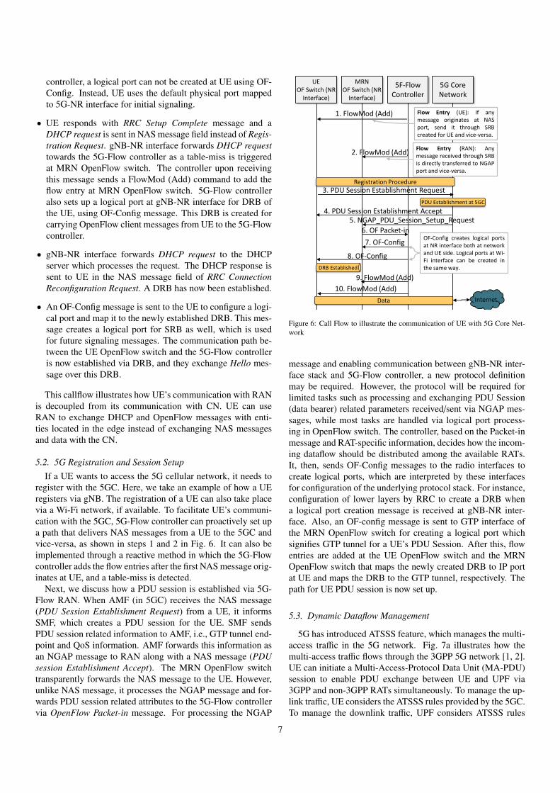
controller, a logical port can not be created at UE using OF-Config. Instead, UE uses the default physical port mappedto 5G-NR interface for initial signaling.
• UE responds with RRC Setup Complete message and aDHCP request is sent in NAS message field instead of Regis-tration Request. gNB-NR interface forwards DHCP requesttowards the 5G-Flow controller as a table-miss is triggeredat MRN OpenFlow switch. The controller upon receivingthis message sends a FlowMod (Add) command to add theflow entry at MRN OpenFlow switch. 5G-Flow controlleralso sets up a logical port at gNB-NR interface for DRB ofthe UE, using OF-Config message. This DRB is created forcarrying OpenFlow client messages from UE to the 5G-Flowcontroller.
• gNB-NR interface forwards DHCP request to the DHCPserver which processes the request. The DHCP response issent to UE in the NAS message field of RRC ConnectionReconfiguration Request. A DRB has now been established.
• An OF-Config message is sent to the UE to configure a logi-cal port and map it to the newly established DRB. This mes-sage creates a logical port for SRB as well, which is usedfor future signaling messages. The communication path be-tween the UE OpenFlow switch and the 5G-Flow controlleris now established via DRB, and they exchange Hello mes-sage over this DRB.
This callflow illustrates how UE’s communication with RANis decoupled from its communication with CN. UE can useRAN to exchange DHCP and OpenFlow messages with enti-ties located in the edge instead of exchanging NAS messagesand data with the CN.
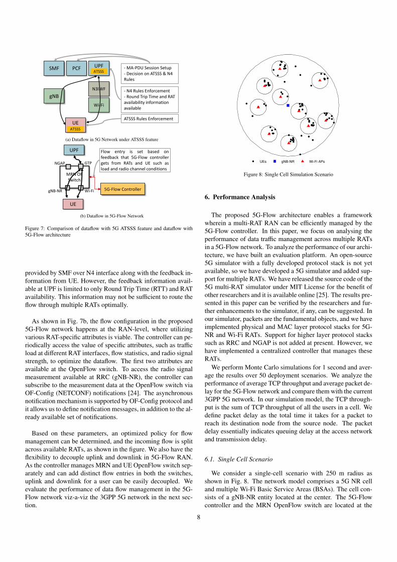
5.2. 5G Registration and Session SetupIf a UE wants to access the 5G cellular network, it needs to
register with the 5GC. Here, we take an example of how a UEregisters via gNB. The registration of a UE can also take placevia a Wi-Fi network, if available. To facilitate UE’s communi-cation with the 5GC, 5G-Flow controller can proactively set upa path that delivers NAS messages from a UE to the 5GC andvice-versa, as shown in steps 1 and 2 in Fig. 6. It can also beimplemented through a reactive method in which the 5G-Flowcontroller adds the flow entries after the first NAS message orig-inates at UE, and a table-miss is detected.
Next, we discuss how a PDU session is established via 5G-Flow RAN. When AMF (in 5GC) receives the NAS message(PDU Session Establishment Request) from a UE, it informsSMF, which creates a PDU session for the UE. SMF sendsPDU session related information to AMF, i.e., GTP tunnel end-point and QoS information. AMF forwards this information asan NGAP message to RAN along with a NAS message (PDUsession Establishment Accept). The MRN OpenFlow switchtransparently forwards the NAS message to the UE. However,unlike NAS message, it processes the NGAP message and for-wards PDU session related attributes to the 5G-Flow controllervia OpenFlow Packet-in message. For processing the NGAP
UE OF Switch (NR
Interface)
MRNOF Switch (NR
Interface)
5F-Flow Controller
5G Core Network
Flow Entry (UE): If anymessage originates at NASport, send it through SRBcreated for UE and vice-versa.
1. FlowMod (Add)
2. FlowMod (Add)
Registration Procedure
Flow Entry (RAN): Anymessage received through SRBis directly transferred to NGAPport and vice-versa.
3. PDU Session Establishment Request
PDU Establishment at 5GC
5. NGAP_PDU_Session_Setup_Request
6. OF Packet-in
7. OF-Config
8. OF-Config
InternetData
4. PDU Session Establishment Accept
OF-Config creates logical portsat NR interface both at networkand UE side. Logical ports at Wi-Fi interface can be created inthe same way.DRB Established
9. FlowMod (Add)
10. FlowMod (Add)
Figure 6: Call Flow to illustrate the communication of UE with 5G Core Net-work
message and enabling communication between gNB-NR inter-face stack and 5G-Flow controller, a new protocol definitionmay be required. However, the protocol will be required forlimited tasks such as processing and exchanging PDU Session(data bearer) related parameters received/sent via NGAP mes-sages, while most tasks are handled via logical port process-ing in OpenFlow switch. The controller, based on the Packet-inmessage and RAT-specific information, decides how the incom-ing dataflow should be distributed among the available RATs.It, then, sends OF-Config messages to the radio interfaces tocreate logical ports, which are interpreted by these interfacesfor configuration of the underlying protocol stack. For instance,configuration of lower layers by RRC to create a DRB whena logical port creation message is received at gNB-NR inter-face. Also, an OF-config message is sent to GTP interface ofthe MRN OpenFlow switch for creating a logical port whichsignifies GTP tunnel for a UE’s PDU Session. After this, flowentries are added at the UE OpenFlow switch and the MRNOpenFlow switch that maps the newly created DRB to IP portat UE and maps the DRB to the GTP tunnel, respectively. Thepath for UE PDU session is now set up.
5.3. Dynamic Dataflow Management
5G has introduced ATSSS feature, which manages the multi-access traffic in the 5G network. Fig. 7a illustrates how themulti-access traffic flows through the 3GPP 5G network [1, 2].UE can initiate a Multi-Access-Protocol Data Unit (MA-PDU)session to enable PDU exchange between UE and UPF via3GPP and non-3GPP RATs simultaneously. To manage the up-link traffic, UE considers the ATSSS rules provided by the 5GC.To manage the downlink traffic, UPF considers ATSSS rules
7
SMF
UE
gNB
PCF UPF
Wi-Fi
N3IWF
ATSSS
ATSSS
- N4 Rules Enforcement- Round Trip Time and RAT availability information available
- MA-PDU Session Setup- Decision on ATSSS & N4 Rules
ATSSS Rules Enforcement
(a) Dataflow in 5G Network under ATSSS feature
5G-Flow Controller
UE
UPF
MRN OF Switch
Flow entry is set based onfeedback that 5G-Flow controllergets from RATs and UE such asload and radio channel conditions
gNB-NR Wi-Fi
GTPNGAP
(b) Dataflow in 5G-Flow Network
Figure 7: Comparison of dataflow with 5G ATSSS feature and dataflow with5G-Flow architecture
provided by SMF over N4 interface along with the feedback in-formation from UE. However, the feedback information avail-able at UPF is limited to only Round Trip Time (RTT) and RATavailability. This information may not be sufficient to route theflow through multiple RATs optimally.
As shown in Fig. 7b, the flow configuration in the proposed5G-Flow network happens at the RAN-level, where utilizingvarious RAT-specific attributes is viable. The controller can pe-riodically access the value of specific attributes, such as trafficload at different RAT interfaces, flow statistics, and radio signalstrength, to optimize the dataflow. The first two attributes areavailable at the OpenFlow switch. To access the radio signalmeasurement available at RRC (gNB-NR), the controller cansubscribe to the measurement data at the OpenFlow switch viaOF-Config (NETCONF) notifications [24]. The asynchronousnotification mechanism is supported by OF-Config protocol andit allows us to define notification messages, in addition to the al-ready available set of notifications.
Based on these parameters, an optimized policy for flowmanagement can be determined, and the incoming flow is splitacross available RATs, as shown in the figure. We also have theflexibility to decouple uplink and downlink in 5G-Flow RAN.As the controller manages MRN and UE OpenFlow switch sep-arately and can add distinct flow entries in both the switches,uplink and downlink for a user can be easily decoupled. Weevaluate the performance of data flow management in the 5G-Flow network viz-a-viz the 3GPP 5G network in the next sec-tion.
UEs gNB-NR Wi-Fi APs
Figure 8: Single Cell Simulation Scenario
6. Performance Analysis
The proposed 5G-Flow architecture enables a frameworkwherein a multi-RAT RAN can be efficiently managed by the5G-Flow controller. In this paper, we focus on analysing theperformance of data traffic management across multiple RATsin a 5G-Flow network. To analyze the performance of our archi-tecture, we have built an evaluation platform. An open-source5G simulator with a fully developed protocol stack is not yetavailable, so we have developed a 5G simulator and added sup-port for multiple RATs. We have released the source code of the5G multi-RAT simulator under MIT License for the benefit ofother researchers and it is available online [25]. The results pre-sented in this paper can be verified by the researchers and fur-ther enhancements to the simulator, if any, can be suggested. Inour simulator, packets are the fundamental objects, and we haveimplemented physical and MAC layer protocol stacks for 5G-NR and Wi-Fi RATs. Support for higher layer protocol stackssuch as RRC and NGAP is not added at present. However, wehave implemented a centralized controller that manages theseRATs.
We perform Monte Carlo simulations for 1 second and aver-age the results over 50 deployment scenarios. We analyze theperformance of average TCP throughput and average packet de-lay for the 5G-Flow network and compare them with the current3GPP 5G network. In our simulation model, the TCP through-put is the sum of TCP throughput of all the users in a cell. Wedefine packet delay as the total time it takes for a packet toreach its destination node from the source node. The packetdelay essentially indicates queuing delay at the access networkand transmission delay.
6.1. Single Cell Scenario
We consider a single-cell scenario with 250 m radius asshown in Fig. 8. The network model comprises a 5G NR celland multiple Wi-Fi Basic Service Areas (BSAs). The cell con-sists of a gNB-NR entity located at the center. The 5G-Flowcontroller and the MRN OpenFlow switch are located at the
8
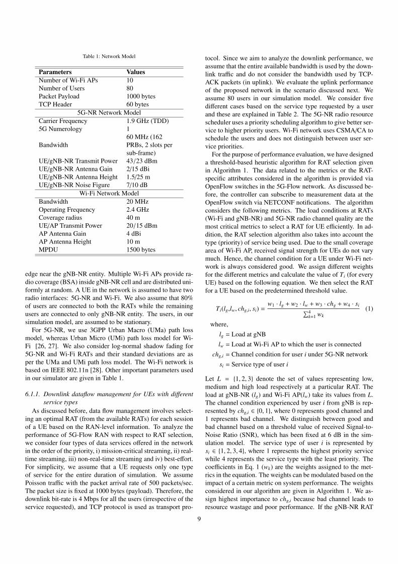
Table 1: Network Model
Parameters ValuesNumber of Wi-Fi APs 10Number of Users 80Packet Payload 1000 bytesTCP Header 60 bytes
5G-NR Network ModelCarrier Frequency 1.9 GHz (TDD)5G Numerology 1
Bandwidth60 MHz (162PRBs, 2 slots persub-frame)
UE/gNB-NR Transmit Power 43/23 dBmUE/gNB-NR Antenna Gain 2/15 dBiUE/gNB-NR Antenna Height 1.5/25 mUE/gNB-NR Noise Figure 7/10 dB
Wi-Fi Network ModelBandwidth 20 MHzOperating Frequency 2.4 GHzCoverage radius 40 mUE/AP Transmit Power 20/15 dBmAP Antenna Gain 4 dBiAP Antenna Height 10 mMPDU 1500 bytes
edge near the gNB-NR entity. Multiple Wi-Fi APs provide ra-dio coverage (BSA) inside gNB-NR cell and are distributed uni-formly at random. A UE in the network is assumed to have tworadio interfaces: 5G-NR and Wi-Fi. We also assume that 80%of users are connected to both the RATs while the remainingusers are connected to only gNB-NR entity. The users, in oursimulation model, are assumed to be stationary.
For 5G-NR, we use 3GPP Urban Macro (UMa) path lossmodel, whereas Urban Micro (UMi) path loss model for Wi-Fi [26, 27]. We also consider log-normal shadow fading for5G-NR and Wi-Fi RATs and their standard deviations are asper the UMa and UMi path loss model. The Wi-Fi network isbased on IEEE 802.11n [28]. Other important parameters usedin our simulator are given in Table 1.
6.1.1. Downlink dataflow management for UEs with differentservice types
As discussed before, data flow management involves select-ing an optimal RAT (from the available RATs) for each sessionof a UE based on the RAN-level information. To analyze theperformance of 5G-Flow RAN with respect to RAT selection,we consider four types of data services offered in the networkin the order of the priority, i) mission-critical streaming, ii) real-time streaming, iii) non-real-time streaming and iv) best-effort.For simplicity, we assume that a UE requests only one typeof service for the entire duration of simulation. We assumePoisson traffic with the packet arrival rate of 500 packets/sec.The packet size is fixed at 1000 bytes (payload). Therefore, thedownlink bit-rate is 4 Mbps for all the users (irrespective of theservice requested), and TCP protocol is used as transport pro-
tocol. Since we aim to analyze the downlink performance, weassume that the entire available bandwidth is used by the down-link traffic and do not consider the bandwidth used by TCP-ACK packets (in uplink). We evaluate the uplink performanceof the proposed network in the scenario discussed next. Weassume 80 users in our simulation model. We consider fivedifferent cases based on the service type requested by a userand these are explained in Table 2. The 5G-NR radio resourcescheduler uses a priority scheduling algorithm to give better ser-vice to higher priority users. Wi-Fi network uses CSMA/CA toschedule the users and does not distinguish between user ser-vice priorities.
For the purpose of performance evaluation, we have designeda threshold-based heuristic algorithm for RAT selection givenin Algorithm 1. The data related to the metrics or the RAT-specific attributes considered in the algorithm is provided viaOpenFlow switches in the 5G-Flow network. As discussed be-fore, the controller can subscribe to measurement data at theOpenFlow switch via NETCONF notifications. The algorithmconsiders the following metrics. The load conditions at RATs(Wi-Fi and gNB-NR) and 5G-NR radio channel quality are themost critical metrics to select a RAT for UE efficiently. In ad-dition, the RAT selection algorithm also takes into account thetype (priority) of service being used. Due to the small coveragearea of Wi-Fi AP, received signal strength for UEs do not varymuch. Hence, the channel condition for a UE under Wi-Fi net-work is always considered good. We assign different weightsfor the different metrics and calculate the value of Ti (for everyUE) based on the following equation. We then select the RATfor a UE based on the predetermined threshold value.
Ti(lg,lw, chg,i, si) =w1 · lg + w2 · lw + w3 · chg + w4 · si∑4
k=1 wk(1)
where,lg = Load at gNBlw = Load at Wi-Fi AP to which the user is connected
chg,i = Channel condition for user i under 5G-NR networksi = Service type of user i
Let L = {1, 2, 3} denote the set of values representing low,medium and high load respectively at a particular RAT. Theload at gNB-NR (lg) and Wi-Fi AP(lw) take its values from L.The channel condition experienced by user i from gNB is rep-resented by chg,i ∈ {0, 1}, where 0 represents good channel and1 represents bad channel. We distinguish between good andbad channel based on a threshold value of received Signal-to-Noise Ratio (SNR), which has been fixed at 6 dB in the sim-ulation model. The service type of user i is represented bysi ∈ {1, 2, 3, 4}, where 1 represents the highest priority servicewhile 4 represents the service type with the least priority. Thecoefficients in Eq. 1 (wk) are the weights assigned to the met-rics in the equation. The weights can be modulated based on theimpact of a certain metric on system performance. The weightsconsidered in our algorithm are given in Algorithm 1. We as-sign highest importance to chg,i because bad channel leads toresource wastage and poor performance. If the gNB-NR RAT
9
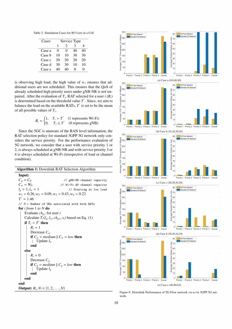
Table 2: Simulation Cases for 80 Users in a Cell
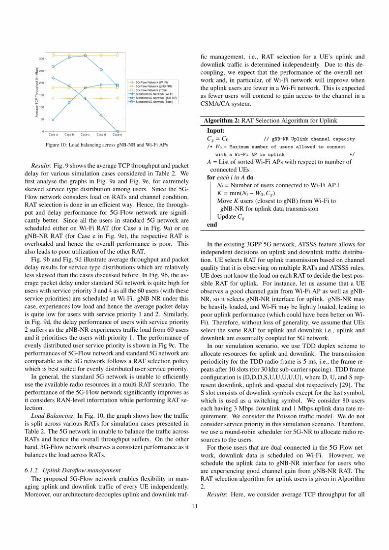
Cases Service Type1 2 3 4
Case a 0 0 40 40Case b 10 10 30 30Case c 20 20 20 20Case d 30 30 10 10Case e 40 40 0 0
is observing high load, the high value of w1 ensures that ad-ditional users are not scheduled. This ensures that the QoS ofalready scheduled high priority users under gNB-NR is not im-paired. After the evaluation of Ti, RAT selected for a user i (Ri)is determined based on the threshold value T
′
. Since, we aim tobalance the load on the available RATs, T
′
is set to be the meanof all possible values of Ti.
Ri =
{1, Ti > T
′
(1 represents Wi-Fi)0, Ti ≤ T
′
(0 represents gNB)
Since the 5GC is unaware of the RAN level information, theRAT selection policy for standard 3GPP 5G network only con-siders the service priority. For the performance evaluation of5G network, we consider that a user with service priority 1 or2, is always scheduled at gNB-NR and with service priority 3 or4 is always scheduled at Wi-Fi (irrespective of load or channelcondition).
Algorithm 1: Downlink RAT Selection Algorithm
Input:Cg = C0 // gNB-NR channel capacity
Cw = W0 // Wi-Fi AP channel capacity
lg = 1, lw = 1 // Starting at low load
w1 = 0.26,w2 = 0.09,w3 = 0.43,w4 = 0.22T′
= 1.46// N = Number of UEs associated with both RATs
for i from 1 to N doEvaluate chg,i for user iCalculate Ti(lg, lw, chg,i, si) based on Eq. (1)if Ti > T
′ thenRi = 1Decrease Cw
if Cw = medium || Cw = low thenUpdate lw
endelse
Ri = 0Decrease Cg
if Cg = medium || Cg = low thenUpdate lg
endend
endOutput: Ri,∀i ∈ {1, 2, . . . ,N}
Priority 1 Priority 2 Priority 3 Priority 4 Overall0
50
100
150
200
250
300
350
Avera
ge T
CP
Thro
ughput (in M
bps) 5G-Flow Network
Standard 5G Network
Priority 1 Priority 2 Priority 3 Priority 4 Overall0
10
20
30
40
50
60
70
80
Avera
ge P
acket D
ela
y (
in m
s)
5G-Flow Network
Standard 5G Network
(a) Case a (0,0,40,40)
Priority 1 Priority 2 Priority 3 Priority 4 Overall0
50
100
150
200
250
300
350
Avera
ge T
CP
Thro
ughput (in M
bps) 5G-Flow Network
Standard 5G Network
Priority 1 Priority 2 Priority 3 Priority 4 Overall0
10
20
30
40
50
60
70
80
Avera
ge P
acket D
ela
y (
in m
s)
5G-Flow Network
Standard 5G Network
(b) Case b (10,10,30,30)
Priority 1 Priority 2 Priority 3 Priority 4 Overall0
50
100
150
200
250
300
350
Avera
ge T
CP
Thro
ughput (in M
bps) 5G-Flow Network
Standard 5G Network
Priority 1 Priority 2 Priority 3 Priority 4 Overall0
10
20
30
40
50
60
70
80
Avera
ge P
acket D
ela
y (
in m
s)
5G-Flow Network
Standard 5G Network
(c) Case c (20,20,20,20)
Priority 1 Priority 2 Priority 3 Priority 4 Overall0
50
100
150
200
250
300
350
Avera
ge T
CP
Thro
ughput (in M
bps) 5G-Flow Network
Standard 5G Network
Priority 1 Priority 2 Priority 3 Priority 4 Overall0
10
20
30
40
50
60
70
80
Avera
ge P
acket D
ela
y (
in m
s)
5G-Flow Network
Standard 5G Network
(d) Case d (30,30,10,10)
Priority 1 Priority 2 Priority 3 Priority 4 Overall0
50
100
150
200
250
300
350
Avera
ge T
CP
Thro
ughput (in M
bps) 5G-Flow Network
Standard 5G Network
Priority 1 Priority 2 Priority 3 Priority 4 Overall0
10
20
30
40
50
60
70
80
Avera
ge P
acket D
ela
y (
in m
s)
5G-Flow Network
Standard 5G Network
(e) Case e (40,40,0,0)
Figure 9: Downlink Performance of 5G-Flow network vis-a-vis 3GPP 5G net-work.
10
Case a Case b Case c Case d Case e0
50
100
150
200
250
300
Avera
ge T
CP
Thro
ughput (in M
bps)
5G-Flow Network (Wi-Fi)
5G-Flow Network (gNB-NR)
5G-Flow Network (Total)
Standard 5G Network (Wi-Fi)
Standard 5G Network (gNB-NR)
Standard 5G Network (Total)
Figure 10: Load balancing across gNB-NR and Wi-Fi APs
Results: Fig. 9 shows the average TCP throughput and packetdelay for various simulation cases considered in Table 2. Wefirst analyse the graphs in Fig. 9a and Fig. 9e, for extremelyskewed service type distribution among users. Since the 5G-Flow network considers load on RATs and channel condition,RAT selection is done in an efficient way. Hence, the through-put and delay performance for 5G-Flow network are signifi-cantly better. Since all the users in standard 5G network arescheduled either on Wi-Fi RAT (for Case a in Fig. 9a) or ongNB-NR RAT (for Case e in Fig. 9e), the respective RAT isoverloaded and hence the overall performance is poor. Thisalso leads to poor utilization of the other RAT.
Fig. 9b and Fig. 9d illustrate average throughput and packetdelay results for service type distributions which are relativelyless skewed than the cases discussed before. In Fig. 9b, the av-erage packet delay under standard 5G network is quite high forusers with service priority 3 and 4 as all the 60 users (with theseservice priorities) are scheduled at Wi-Fi. gNB-NR under thiscase, experiences low load and hence the average packet delayis quite low for users with service priority 1 and 2. Similarly,in Fig. 9d, the delay performance of users with service priority2 suffers as the gNB-NR experiences traffic load from 60 usersand it prioritises the users with priority 1. The performance ofevenly distributed user service priority is shown in Fig 9c. Theperformances of 5G-Flow network and standard 5G network arecomparable as the 5G network follows a RAT selection policywhich is best suited for evenly distributed user service priority.
In general, the standard 5G network is unable to efficientlyuse the available radio resources in a multi-RAT scenario. Theperformance of the 5G-Flow network significantly improves asit considers RAN-level information while performing RAT se-lection.
Load Balancing: In Fig. 10, the graph shows how the trafficis split across various RATs for simulation cases presented inTable 2. The 5G network in unable to balance the traffic acrossRATs and hence the overall throughput suffers. On the otherhand, 5G-Flow network observes a consistent performance as itbalances the load across RATs.
6.1.2. Uplink Dataflow managementThe proposed 5G-Flow network enables flexibility in man-
aging uplink and downlink traffic of every UE independently.Moreover, our architecture decouples uplink and downlink traf-
fic management, i.e., RAT selection for a UE’s uplink anddownlink traffic is determined independently. Due to this de-coupling, we expect that the performance of the overall net-work and, in particular, of Wi-Fi network will improve whenthe uplink users are fewer in a Wi-Fi network. This is expectedas fewer users will contend to gain access to the channel in aCSMA/CA system.
Algorithm 2: RAT Selection Algorithm for Uplink
Input:Cg = C0 // gNB-NR Uplink channel capacity
/* W0 = Maximum number of users allowed to connect
with a Wi-Fi AP in uplink */
A = List of sorted Wi-Fi APs with respect to number ofconnected UEs
for each i in A doNi = Number of users connected to Wi-Fi AP iK = min(Ni −W0,Cg)Move K users (closest to gNB) from Wi-Fi to
gNB-NR for uplink data transmissionUpdate Cg
end
In the existing 3GPP 5G network, ATSSS feature allows forindependent decisions on uplink and downlink traffic distribu-tion. UE selects RAT for uplink transmission based on channelquality that it is observing on multiple RATs and ATSSS rules.UE does not know the load on each RAT to decide the best pos-sible RAT for uplink. For instance, let us assume that a UEobserves a good channel gain from Wi-Fi AP as well as gNB-NR, so it selects gNB-NR interface for uplink. gNB-NR maybe heavily loaded, and Wi-Fi may be lightly loaded, leading topoor uplink performance (which could have been better on Wi-Fi). Therefore, without loss of generality, we assume that UEsselect the same RAT for uplink and downlink i.e., uplink anddownlink are essentially coupled for 5G network.
In our simulation scenario, we use TDD duplex scheme toallocate resources for uplink and downlink. The transmissionperiodicity for the TDD radio frame is 5 ms, i.e., the frame re-peats after 10 slots (for 30 khz sub-carrier spacing). TDD frameconfiguration is {D,D,D,S,U,U,U,U,U}, where D, U, and S rep-resent downlink, uplink and special slot respectively [29]. TheS slot consists of downlink symbols except for the last symbol,which is used as a switching symbol. We consider 80 userseach having 3 Mbps downlink and 1 Mbps uplink data rate re-quirement. We consider the Poisson traffic model. We do notconsider service priority in this simulation scenario. Therefore,we use a round-robin scheduler for 5G-NR to allocate radio re-sources to the users.
For those users that are dual-connected in the 5G-Flow net-work, downlink data is scheduled on Wi-Fi. However, weschedule the uplink data to gNB-NR interface for users whoare experiencing good channel gain from gNB-NR RAT. TheRAT selection algorithm for uplink users is given in Algorithm2.
Results: Here, we consider average TCP throughput for all
11
Downlink Uplink0
50
100
150
200
250
TC
P T
hro
ug
hp
ut
(in
Mb
ps)
5G-Flow Network
Standard 5G Network
Downlink Uplink0
20
40
60
80
100
120
140
Avera
ge P
acket D
ela
y (
in m
s) 5G-Flow Network
Standard 5G Network
Figure 11: Performance comparison between 5G-Flow network and Standard5G network when Uplink and Downlink data flows are decoupled.
the users in downlink direction and uplink direction separately.Fig. 11 demonstrates that downlink TCP throughput is higherfor the 5G-Flow network as compared to the standard 5G net-work. We also observe the percentage of served traffic to of-fered traffic for Wi-Fi APs in our simulations. While it is75.87% under standard 3GPP 5G network, it is 88.5% for 5G-Flow network. This improvement in 5G-Flow network is ob-served due to the reduction in load at Wi-Fi APs as we haveefficiently managed uplink users based on Algorithm 2. There-fore, fewer users contend to gain access to channel under Wi-FiAPs in 5G-Flow network, thereby increasing performance ef-ficiency of Wi-Fi APs. For the same reason, the delay perfor-mance has also significantly improved.
6.2. Multi-cell Scenario
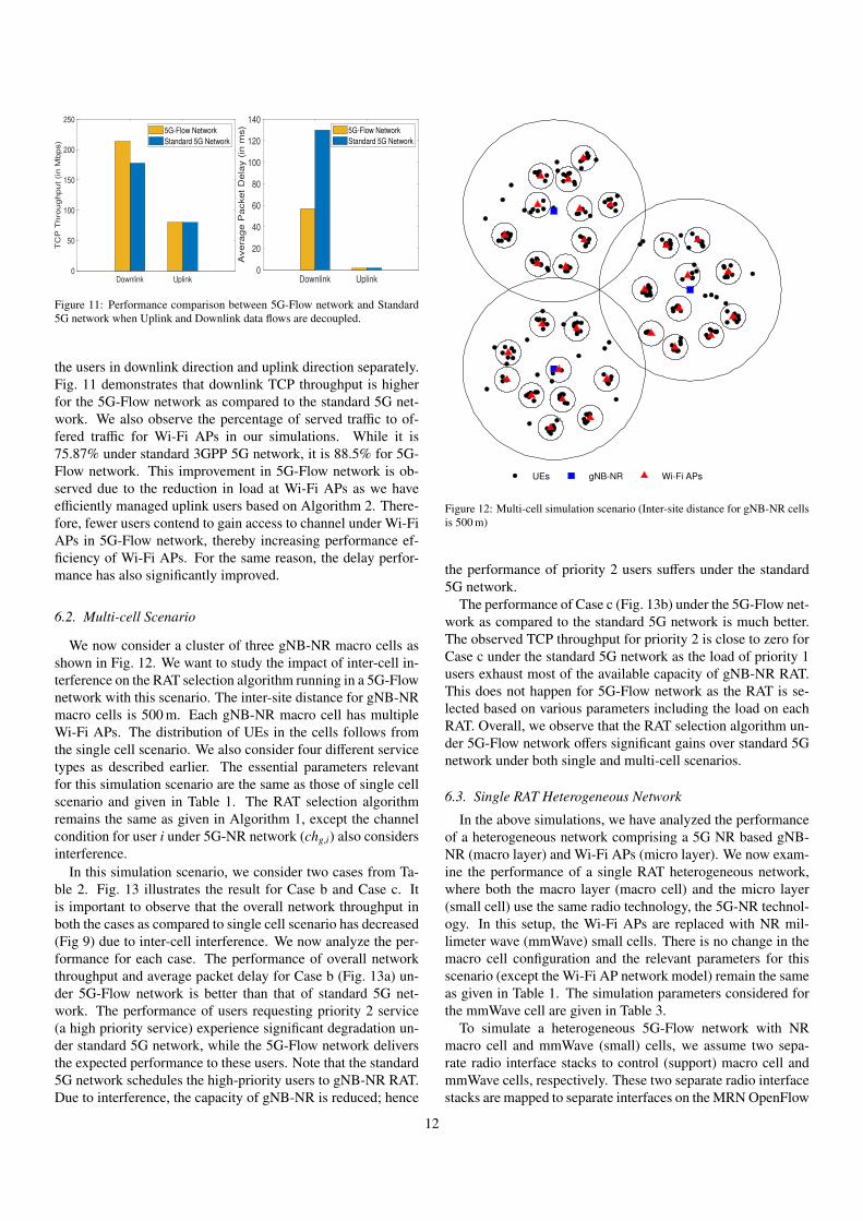
We now consider a cluster of three gNB-NR macro cells asshown in Fig. 12. We want to study the impact of inter-cell in-terference on the RAT selection algorithm running in a 5G-Flownetwork with this scenario. The inter-site distance for gNB-NRmacro cells is 500 m. Each gNB-NR macro cell has multipleWi-Fi APs. The distribution of UEs in the cells follows fromthe single cell scenario. We also consider four different servicetypes as described earlier. The essential parameters relevantfor this simulation scenario are the same as those of single cellscenario and given in Table 1. The RAT selection algorithmremains the same as given in Algorithm 1, except the channelcondition for user i under 5G-NR network (chg,i) also considersinterference.
In this simulation scenario, we consider two cases from Ta-ble 2. Fig. 13 illustrates the result for Case b and Case c. Itis important to observe that the overall network throughput inboth the cases as compared to single cell scenario has decreased(Fig 9) due to inter-cell interference. We now analyze the per-formance for each case. The performance of overall networkthroughput and average packet delay for Case b (Fig. 13a) un-der 5G-Flow network is better than that of standard 5G net-work. The performance of users requesting priority 2 service(a high priority service) experience significant degradation un-der standard 5G network, while the 5G-Flow network deliversthe expected performance to these users. Note that the standard5G network schedules the high-priority users to gNB-NR RAT.Due to interference, the capacity of gNB-NR is reduced; hence
UEs gNB-NR Wi-Fi APs
Figure 12: Multi-cell simulation scenario (Inter-site distance for gNB-NR cellsis 500 m)
the performance of priority 2 users suffers under the standard5G network.
The performance of Case c (Fig. 13b) under the 5G-Flow net-work as compared to the standard 5G network is much better.The observed TCP throughput for priority 2 is close to zero forCase c under the standard 5G network as the load of priority 1users exhaust most of the available capacity of gNB-NR RAT.This does not happen for 5G-Flow network as the RAT is se-lected based on various parameters including the load on eachRAT. Overall, we observe that the RAT selection algorithm un-der 5G-Flow network offers significant gains over standard 5Gnetwork under both single and multi-cell scenarios.
6.3. Single RAT Heterogeneous Network
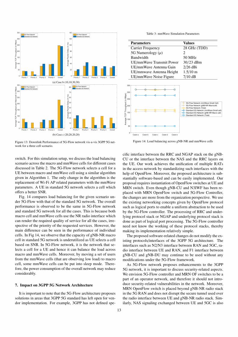
In the above simulations, we have analyzed the performanceof a heterogeneous network comprising a 5G NR based gNB-NR (macro layer) and Wi-Fi APs (micro layer). We now exam-ine the performance of a single RAT heterogeneous network,where both the macro layer (macro cell) and the micro layer(small cell) use the same radio technology, the 5G-NR technol-ogy. In this setup, the Wi-Fi APs are replaced with NR mil-limeter wave (mmWave) small cells. There is no change in themacro cell configuration and the relevant parameters for thisscenario (except the Wi-Fi AP network model) remain the sameas given in Table 1. The simulation parameters considered forthe mmWave cell are given in Table 3.
To simulate a heterogeneous 5G-Flow network with NRmacro cell and mmWave (small) cells, we assume two sepa-rate radio interface stacks to control (support) macro cell andmmWave cells, respectively. These two separate radio interfacestacks are mapped to separate interfaces on the MRN OpenFlow
12
Priority 1 Priority 2 Priority 3 Priority 4 Overall0
50
100
150
200
250
300
350
Ave
rage
TC
P T
hro
ug
hpu
t (in M
bp
s)
5G-Flow Network
Standard 5G Network
Priority 1 Priority 2 Priority 3 Priority 4 Overall0
20
40
60
80
100
120
140
Avera
ge
Packe
t D
ela
y (
in m
s)
5G-Flow Network
Standard 5G Network
(a) Case b (10,10,30,30)
Priority 1 Priority 2 Priority 3 Priority 4 Overall0
50
100
150
200
250
300
350
Ave
rag
e T
CP
Th
roug
hpu
t pe
r M
acro
cell
(in M
bps) 5G-Flow Network
Standard 5G Network
Priority 1 Priority 2 Priority 3 Priority 4 Overall0
10
20
30
40
50
60
70
80
Ave
rag
e P
acke
t D
ela
y (
in m
s)
5G-Flow Network
Standard 5G Network
(b) Case c (20,20,20,20)
Figure 13: Downlink Performance of 5G-Flow network vis-a-vis 3GPP 5G net-work for a three cell scenario.
switch. For this simulation setup, we discuss the load balancingscenario across the macro and mmWave cells for different casesdiscussed in Table 2. The 5G-Flow network selects a cell for aUE between macro and mmWave cell using a similar algorithmgiven in Algorithm 1. The only change in the algorithm is thereplacement of Wi-Fi AP related parameters with the mmWaveparameters. A UE in standard 5G network selects a cell whichoffers a better SNR.
Fig. 14 compares load balancing for the given scenario un-der 5G-Flow with that of the standard 5G network. The overallperformance is observed to be the same in 5G-Flow networkand standard 5G network for all the cases. This is because bothmacro cell and mmWave cells use the NR radio interface whichcan render the required quality of service for all the cases, irre-spective of the priority of the requested services. However, themain difference can be seen in the performance of individualcells. In Fig 14, we observe that the capacity of gNB-NR macrocell in standard 5G network is underutilized as UE selects a cellbased on SNR. In 5G-Flow network, it is the network that se-lects a cell for a UE and hence it can balance the load acrossmacro and mmWave cells. Moreover, by moving a set of usersfrom the mmWave cells (that are observing low load) to macrocell, some mmWave cells can be put into sleep mode. There-fore, the power consumption of the overall network may reduceconsiderably.
7. Impact on 3GPP 5G Network Architecture
It is important to note that the 5G-Flow architecture proposessolutions in areas that 3GPP 5G standard has left open for ven-dor implementation. For example, 3GPP has not defined spe-
Table 3: mmWave Simulation Parameters
Parameters ValuesCarrier Frequency 28 GHz (TDD)5G Numerology (µ) 2Bandwidth 50 MHzUE/mmWave Transmit Power 30/23 dBmUE/mmWave Antenna Gain 2/26 dBiUE/mmwave Antenna Height 1.5/10 mUE/mmWave Noise Figure 7/10 dB
Case a Case b Case c Case d Case e0
50
100
150
200
250
300
350
Ave
rag
e T
CP
Th
rou
ghp
ut
(in M
bp
s)
5G-Flow Network (mmWave Small Cell)
5G-Flow Network (gNB-NR Macrocell)
5G-Flow Network (Total)
Standard 5G Network (mmWave Small cell)
Standard 5G Network (gNB-NR Macro cell)
Standard 5G Network (Total)
Figure 14: Load balancing across gNB-NR and mmWave cells
cific interface between the RRC and NGAP stack on the gNB-CU or the interface between the NAS and the RRC layers onthe UE. Our work achieves the unification of multiple RATsin the access network by standardizing such interfaces with thehelp of OpenFlow. Moreover, the proposed architecture is sub-stantially software-based and can be easily implemented. Ourproposal requires instantiation of OpenFlow switches at UE andMRN switch. Even though gNB-CU and N3IWF has been re-placed with MRN OpenFlow switch and 5G-Flow Controller,the changes are more from the organization perspective. We usethe existing networking concepts given by OpenFlow protocolsuch as logical ports to enable a uniform abstraction to be usedby the 5G-Flow controller. The processing of RRC and under-lying protocol stack or NGAP and underlying protocol stack isdone as part of logical port processing. The 5G-Flow controllerneed not know the working of these protocol stacks, therebymaking its implementation relatively simple.
The proposed software-related changes do not modify the ex-isting protocols/interfaces of the 3GPP 5G architecture. Theinterfaces such as N2/N3 interface between RAN and 5GC, ra-dio interface between UE and RAN, and F1 interface betweengNB-CU and gNB-DU may continue to be used without anymodifications under the 5G-Flow framework.
As 5G-Flow network proposes enhancements to the 3GPP5G network, it is important to discuss security-related aspects.We envision 5G-Flow controller and MRN OF switches to be apart of an operator network, and therefore it should not intro-duce security-related vulnerabilities in the network. Moreover,MRN OpenFlow switch is placed beyond gNB-NR radio stackin the 5G RAN and does not disrupt the secure tunnel used overthe radio interface between UE and gNB-NR radio stack. Sim-ilarly, NAS signaling exchanged between UE and 5GC is also
13
encrypted. This is not disturbed by MRN OpenFlow switch(and 5G Flow Controller) as NAS messages are transparentlypassed through MRN OpenFlow switch.
Under the 5G-Flow network, data latency will be reducedin scenarios where a UE communicates directly with an exter-nal data network via RAN, bypassing the core. The signalinglatency is also reduced as NAS signaling can be skipped. How-ever, when a UE communicates with 5GC, additional signal-ing messages between UE OpenFlow switch and 5G-Flow con-troller may slightly increase the signaling latency. We view thisas a reasonable trade-off required to decouple UE’s communi-cation with RAN from its communication with 5GC. Moreover,as there are only a few additional signaling messages, their im-pact on UE’s latency and battery will be minimal.
8. Applications
In this section, we present some important applications of5G-Flow RAN architecture below. Although, we discuss onlytwo applications due to space constraints, 5G-Flow architecturecan help support other use-cases too.
8.1. Direct Internet Connectivity via RAN
A UE in the existing 3GPP cellular network can access In-ternet solely through the CN. It does not have the flexibility toconnect to the Internet directly from the RAN bypassing theCN. This feature can be beneficial in those areas where usersare mostly stationary, and therefore a data tunnel through CNmay not be required. However, the advantages of the cellularstack with an efficient L2/L1 layer can still be exploited.
We now discuss the procedure to access the Internet directlybypassing the CN. A UE sends a packet to the IP interface of theUE OpenFlow switch and a table-miss is observed. On table-miss, the UE OpenFlow switch forwards the packet to the 5G-Flow controller via OF Packet-in message. Depending on theQoS requirement, the controller decides whether a dedicatedDRB needs to be created. In case a dedicated DRB is required,the controller sends an OF-Config message to gNB-NR inter-face to create a logical port, which is translated by RRC layerand a DRB is created using RRC Reconfiguration messages. AnOF-Config message is also sent to the UE so that it can create alogical port on the NR interface and map the newly establishedDRB to the logical port. The 5G-Flow controller adds the ap-propriate flow entries at UE and MRN OpenFlow switch so thatthe UE can access the Internet.
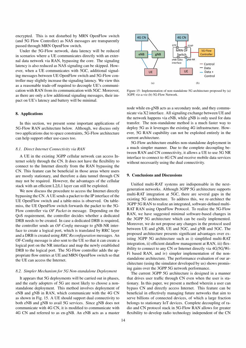
8.2. Simpler Mechanism for 5G Non-standalone Deployment
It appears that 5G deployments will be carried out in phases,and the early adopters of 5G are most likely to choose a non-standalone deployment. This method involves deployment ofeNB and gNB in RAN, which communicate with the 4G CNas shown in Fig. 15. A UE should support dual connectivity toboth eNB and gNB to avail 5G services. Since gNB does notcommunicate with 4G CN, it is modified to communicate with4G CN and referred to as en-gNB. An eNB acts as a master
UE
4G CN
eNB gNB
(a)
4G CN
MRN OF Switch
5G-FlowController
gNB-NReNB-radio interface Control
DataUE Data +
Control
S1APGTP
(b)
Figure 15: Implementation of non-standalone 5G architecture proposed by (a)3GPP, viz-a-viz (b) 5G-Flow Network.
node while en-gNB acts as a secondary node, and they commu-nicate via X2 interface. All signaling exchange between UE andthe network happens via eNB, while gNB is only used for datatransfer. The non-standalone method is a much faster way todeploy 5G as it leverages the existing 4G infrastructure. How-ever, 5G RAN capability can not be exploited entirely in thecurrent architecture.
5G-Flow architecture enables non-standalone deployment ina much simpler manner. Due to the complete decoupling be-tween RAN and CN connectivity, it allows a UE to use 5G NRinterface to connect to 4G CN and receive mobile data serviceswithout necessarily using the dual connectivity.
9. Conclusions and Discussions
Unified multi-RAT systems are indispensable in the next-generation networks. Although 3GPP 5G architecture supportsmulti-RAT integration at 5GC, there are several gaps in theexisting 5G architecture. To address this, we re-architect the3GPP 5G RAN to realize an integrated, software-defined multi-RAT RAN using OpenFlow Protocol. To realize the 5G-FlowRAN, we have suggested minimal software-based changes inthe 3GPP 5G architecture which can be easily implemented.Moreover, we do not propose any changes in the protocol usedbetween UE and gNB, UE and 5GC, and gNB and 5GC. Theproposed architecture presents significant advantages over ex-isting 3GPP 5G architecture such as i) simplified multi-RATintegration, ii) efficient dataflow management at RAN, iii) flex-ibility to connect to any CN or Internet directly via 4G/5G/Wi-Fi based RAN, and iv) simpler implementation of the non-standalone architecture. The performance evaluation of our ar-chitecture (using the simulator developed by us) shows promis-ing gains over the 3GPP 5G network performance.
The current 3GPP 5G architecture is designed in a mannerthat drives user traffic through CN even when the user is sta-tionary. In this paper, we present a method wherein a user canbypass CN and directly access Internet. This feature can bebeneficial in effectively managing future networks that aim toserve billions of connected devices, of which a large fractionbelongs to stationary IoT devices. Complete decoupling of ra-dio and CN protocol stack in 5G-Flow RAN allows for greaterflexibility to develop radio technology independent of the CN
14
being used. Future networks can exploit this feature to facilitatefaster development cycles for newer RATs.
In future, we aim to propose some enhancements in theOpenFlow and OF-Config protocols to support these 5G spe-cific logical ports. The development of an open protocol foranalyzing and translating NGAP messages for the 5G-Flowcontroller is an important future work. Additionally, we re-quire a modified Yang model to be used with NETCONF, whichcan support event notifications based on the radio measurementdata, NGAP messages, etc. We expect that mobility manage-ment can be effectively handled by introducing a virtual Open-Flow switch (at MRN OpenFlow switch) for every UE. We aimto examine these open issues in the future.
10. Acknowledgement
This work has been supported by the Department ofTelecommunications, Ministry of Communications, India, aspart of the Indigenous 5G Test Bed project.
References
[1] 3GPP TS 23.501 v16.7.0, System Architecture for the 5G System, Tech-nical specification (2020).URL https://www.3gpp.org/DynaReport/23501.htm
[2] 3GPP TS 24.193 v16.2.0, 5G System; Access Traffic Steering, Switchingand Splitting (ATSSS), Technical specification (2020).URL https://www.3gpp.org/DynaReport/24193.htm
[3] OpenFlow Switch Specification, v1.3.0, Technical specification, OpenNetworking Foundation (2014).URL https://www.opennetworking.org/wp-content/uploads/
2014/10/openflow-spec-v1.3.0.pdf
[4] A. Gudipati, D. Perry, L. E. Li, S. Katti, SoftRAN: Software defined radioaccess network, in: Second ACM SIGCOMM workshop on Hot topics inSoftware Defined Networking (HotSDN), 2013, pp. 25–30.
[5] T. Chen, H. Zhang, X. Chen, O. Tirkkonen, SoftMobile: Control evolu-tion for future heterogeneous mobile networks, IEEE Wireless Commu-nications 21 (6) (2014) 70–78.
[6] X. Foukas, N. Nikaein, M. M. Kassem, M. K. Marina, K. Kontovasilis,FlexRAN: A flexible and programmable platform for software-definedradio access networks, in: Conference on emerging Networking EXperi-ments and Technologies (CoNEXT), 2016, pp. 427–441.
[7] H. Wang, S. Chen, H. Xu, M. Ai, Y. Shi, SoftNet: A software defined de-centralized mobile network architecture toward 5G, IEEE Network 29 (2)(2015) 16–22.
[8] C. J. Bernardos, A. De La Oliva, P. Serrano, A. Banchs, L. M. Contr-eras, H. Jin, J. C. Zuniga, An architecture for software defined wirelessnetworking, IEEE Wireless Communications 21 (3) (2014) 52–61.
[9] I. F. Akyildiz, P. Wang, S.-C. Lin, SoftAir: A software defined networkingarchitecture for 5G wireless systems, Computer Networks 85 (2015) 1–18.
[10] X. Jin, L. E. Li, L. Vanbever, J. Rexford, SoftCell: Scalable and Flexi-ble Cellular Core Network Architecture, in: Ninth ACM Conference onEmerging Networking Experiments and Technologies (CoNEXT), 2013,pp. 163–174.
[11] M. Bansal, J. Mehlman, S. Katti, P. Levis, Openradio: a programmablewireless dataplane, in: First workshop on Hot topics in Software DefinedNetworks (HotSDN), 2012, pp. 109–114.
[12] T. De Schepper, P. Bosch, E. Zeljkovic, F. Mahfoudhi, J. Hax-hibeqiri, J. Hoebeke, J. Famaey, S. Latre, ORCHESTRA: Enabling Inter-Technology Network Management in Heterogeneous Wireless Networks,IEEE Transactions on Network and Service Management 15 (4) (2018)1733–1746.
[13] K. K. Yap, M. Kobayashi, R. Sherwood, T. Y. Huang, M. Chan, N. Hand-igol, N. McKeown, OpenRoads: Empowering Research in Mobile Net-works, SIGCOMM Computer Communication Review (CCR) 40 (1)(2010) 125–126. doi:10.1145/1672308.1672331.
[14] K. K. Yap, M. Kobayashi, D. Underhill, S. Seetharaman, P. Kazemian,N. McKeown, The stanford openroads deployment, in: ACM Interna-tional Workshop on Experimental Evaluation and Characterization, 2009,pp. 59–66.
[15] M. Yang, Y. Li, D. Jin, L. Su, S. Ma, L. Zeng, OpenRAN: a software-defined ran architecture via virtualization, ACM SIGCOMM ComputerCommunication Review (CCR) 43 (4) (2013) 549–550.
[16] E. Coronado, S. N. Khan, R. Riggio, 5G-EmPOWER: A Software-Defined Networking Platform for 5G Radio Access Networks, IEEETransactions on Network and Service Management 16 (2) (2019) 715–728. doi:10.1109/TNSM.2019.2908675.
[17] A. N. Manjeshwar, A. Roy, P. Jha, A. Karandikar, Control and Manage-ment of Multiple RATs in Wireless Networks: An SDN Approach, in:IEEE 2nd 5G World Forum (5GWF), 2019, pp. 596–601.
[18] P. K. Taksande, P. Jha, A. Karandikar, P. Chaporkar, Open5G: ASoftware-Defined Networking Protocol for 5G Multi-RAT Wireless Net-works, in: IEEE Wireless Communications and Networking ConferenceWorkshops (WCNCW), 2020, pp. 1–6.
[19] S. Chandrashekar, A. Maeder, C. Sartori, T. Hohne, B. Vejlgaard,D. Chandramouli, 5G multi-RAT multi-connectivity architecture, in:IEEE International Conference on Communications Workshops (ICC),2016, pp. 180–186.
[20] D. Laselva, D. Lopez-Perez, M. Rinne, T. Henttonen, 3GPP LTE-WLANAggregation Technologies: Functionalities and Performance Compari-son, IEEE Communications Magazine 56 (3) (2018) 195–203.
[21] P. Nuggehalli, LTE-WLAN aggregation [Industry Perspectives], IEEEWireless Communications 23 (4) (2016) 4–6.
[22] R. Enns, M. Bjorklund, J. Schoenwaelder, A. Bierman, RFC 6241 - Net-work configuration protocol (NETCONF), Technical specification (June2011).URL https://tools.ietf.org/html/rfc6241
[23] OpenFlow Management and Configuration Protocol, v1.2, Technicalspecification, Open Networking Foundation (2014).URL https://www.opennetworking.org/images/stories/
downloads/sdn-resources/onf-specifications/
openflow-config/of-config-1.2.pdf
[24] OpenFlow Notifications Framework, OpenFlow Management, v1.0,Technical specification, Open Networking Foundation (2013).URL https://www.opennetworking.org/wp-content/uploads/
2013/02/of-notifications-framework-1.0.pdf
[25] 5G-Flow Simulator Source Code (2021).URL https://github.com/MeghnaKhaturia/5G-Flow-RAN
[26] 3GPP TR 38.901 v16.1.0, Study on channel model for frequencies from0.5 to 100 GHz, Technical report (2020).URL https://www.3gpp.org/DynaReport/38.901.htm
[27] IEEE 802.11-14/0882r4, IEEE 802.11ax Channel Model Document,Technical specification (2014).URL https://mentor.ieee.org/802.11/dcn/14/
11-14-0882-04-00ax-tgax-channel-model-document.docx
[28] IEEE Std 802.11-2016, IEEE Standard for Information technol-ogy—Telecommunications and information exchange between systemsLocal and metropolitan area networks—Specific requirements - Part11: Wireless LAN Medium Access Control (MAC) and Physical Layer(PHY) Specifications (2016) 1–3534.
[29] 3GPP TS 38.331 v16.3.1, 5G; NR; Radio Resource Control (RRC); Pro-tocol specification, Technical specification (2021).URL https://www.3gpp.org/dynareport/38331.htm
15