5s lean manufacturing work station design in silver line final … · 2015-10-22 · 1 5s lean...
TRANSCRIPT

1
5S Lean Manufacturing Work Station Design in Silver Line
Victoria Morin [email protected]
Anish Patel [email protected]
Desiree Romero [email protected]
Ashley Sohn [email protected]
New Jersey Governor’s School of Engineering and Technology
24 July 2015
Abstract Productivity and human ergonomics
are important components that industrial factories monitor in order to be successful. Manufacturing businesses use 5S, a means of identifying and eliminating inefficiencies, to improve upon said components. 5S reduces non-value added wastes by limiting body movements and excessive steps taken by the operator. By designing a new screen frame workstation at Silver Line by Andersen, through the rearrangement of printers and bins using the two-bin system, and the installation of a label dispenser, the cycle time for screen frame assembly was reduced by about 5.4 seconds, which allows for production of about 870 more frames per week. The improved model also minimized time spent for supply refills and improved ergonomics. 1. Introduction 1.1 5S Methodology at Silver Line Major goals of manufacturers in the assembly of high-quality products include maximizing efficiency and profit while minimizing human error. Industrial engineers play a critical role in evaluating the product manufacturing process. Lean
manufacturing, a general method of eliminating waste, can be achieved through systematic application of 5S principles. The components of 5S improve productivity with a sustainable approach. When successful, the work of industrial engineers helps to complete tasks in the most efficient and cost-efficient way possible while also satisfying the customers’ demands. Silver Line Window Company aims to improve window and screen production with updated technology and methods of assembly. Reassessing the workstation and subsequently implementing new technological innovations increases production and decreases worker strain.
This project aims to identify areas in need of improvement in the screen room workstation through the lens of industrial engineering, such as the assembly rate of screen frames and efficiency of body movements. The proposed improvements have been incorporated into a redesigned virtual workstation.
The second component of the project is physically constructing the workstation for potential future use. By implementing the 5S process on the workstation to reduce BRIEF scores, a measure of a task’s strenuousness, the work itself will be

2
streamlined. This will create a more ergonomically designed workstation that can increase worker productivity. 2. Background 2.1 Silver Line Building Products Corporation In 1947, Silver Line Building Products Corporation was founded originally as a privately owned corporation in New Jersey.1 Silver Line has since become the largest vinyl window and door manufacturer in North America. In 2006, the Andersen Corporation purchased Silver Line.2 Silver Line by Andersen is currently known for its commitment in building and constructing windows that are durable, energy-efficient, low maintenance, and satisfy customers’ expectations. 2.2 Silver Line’s Manufacturing Approach
Amongst Silver Line's many contributions, the company specifically takes pride in is its construction of windows and frames through manual labor. The screen frame manufacturing process specifically has two workers assigned to each workstation. Each person is given the opportunity to set the station based on their comfort and individual preferences. The workers have the choice of placing bins that contain the frame parts in, above, or underneath the station table, and using a tool or their muscles to attach the corner brackets of the frame into the designated areas. This system allows the workers to work as they please but includes flaws in terms of muscle strain.
Simple, consistent, and repetitive body movements such as bending over,
reaching across, twisting the wrists, arms, or abdomen, bending the knees, elbows, or neck, etc. can cause repetitive stress injury. For example, if a worker places bins underneath the workstation, the workstation is organized, but repeatedly bending over to pick up the bins causes lower back pain that may not be identified until an employee is injured. The nerve supply of the spine does not signal the human body of approaching injury until the person has been injured, which may cause a person to falsely believe that the work process is not causing injury.3
Most employees work eight-hour intervals five days a week, which means that the amount of time to rest and alleviate the pain is less than the amount of time the pain is created weekly. Silver Line recognizes the valid concerns of its employees and strives to incorporate methods of organization and comfort that minimize the amount of different body movements. Reducing employee injuries is beneficial to the workers and also preserves a steady production rate. 2.3 5S Lean Manufacturing
5S refers to the system comprised of five pillars: Sort, Set in Order, Shine, Standardize, and Sustain. It is a methodology for reducing waste and optimizing productivity through an orderly workplace. The daily responsibilities of a manufacturing company include maintaining organization and tidiness for a smooth and efficient flow of operation. The 5S process encourages workers to reduce wasted resources and minimize human error while still sufficiently meeting the demands of the customer and earning high profits for the corporation.4
3
1. Sort Sort, which primarily focuses on the
elimination of unnecessary materials on the workstation and away from the workstation. As simple as this may seem, this element is the stepping stone for the following pillars of 5S because organization is needed for the rest of the process. 2. Set in Order
The next pillar is set in order, which focuses on the arrangement of the necessary materials in an organized manner. Materials are suggested to be within arm length, and set in an order that allows them to have a designated space of their own without any overlapping. 3. Shining
Strategies to enforce the previous pillar include shelves, bins, and daily follow-up cleaning which falls under the category of shining. This step emphasizes cleanliness to ensure machines function properly.
4. Standardizing
Standardizing allows the worker to consistently follow the first three pillars of the 5S method. Creating charts, tables, lists, and schedules could potentially maintain the organization if executed frequently and accurately. 5. Sustain
The final S, sustain, is often the most difficult to achieve but it can have the greatest effect. In order to sustain the pillars of the 5S methodology for work, the employee is suggested to also follow these methods with other events in their lives,
similar to speaking a language. Grasping a new language requires practice in different environments other than the native environment. In terms of the workstation, implementing 5S outside of his or her career could help the worker to fluently organize and maintain cleanliness.
6. Safety A sixth S is sometimes added to the 5S methodology. Safety is added to emphasize that safety concerns should not be neglected when streamlining the work process.
Overall, the purpose of the 5S methodology is to establish and maintain an organized, safe, and high-performance workplace. It lays the foundation for perpetual improvement, cost reductions, profit increases, a safe work area, and eventually, a zero defect rate. Lean manufacturing is a systematic way to improve the workplace, the assembly process, and the quality of the products through production line improvement and optimization.5 2.4 BRIEF Scores
The Baseline Risk Identification of Ergonomic Factors (BRIEF) Survey is used to identify the degree to which a work process is ergonomically acceptable. It is a rating system that addresses each task in the process to see if either the workstation design or the actual work practices expose employees to injury. Nine body areas of the left and right side of their bodies, including shoulders, neck, back, legs, hands, wrists, and elbows are examined in this process.
All aspects of movement, including body angles, posture, twists, and reaches, are

4
scored on a rating system based on their frequency and duration. Other considerations include vibration, temperature, soft tissue compression, impact stress, and glove issues. The total score is an indication of discomfort and potential for injury at the workstation. Based on the numerical range of the score, the job hazard is ranked as low, medium, high, or very high. BRIEF scores can then be used to recommend more suitable alternatives for workers.6 2.5 Takt Time and Cycle Time Takt time, derived from the German word Taktzeit, is the rate at which a finished product must be theoretically completed in order to meet the customer’s demand. For instance, if a company has a takt time of ten minutes, it means every ten minutes, a complete product is produced and on average, a customer is buying a finished product every ten minutes. Therefore, the takt time can also be referred to as the sell rate. Takt time (Tat) equals the available time for production (Ta) divided by the number of required units of production (D), as shown in the following formula:
𝑇𝑎𝑡 =!𝑎!
It is important to note that the time
available for production does not include idle time. The required units of production measures customer demand since it is the number of products the company expects its customer to purchase in a given period of time. Takt time is a derived value as opposed to one that is directly observed.
Cycle time is the recorded, or actual, time required to produce one unit of product.7
Cycle times could potentially include idle time and vary based on each situation.
2.6 Value-Added and Non-Value Added
A process is said to be “value-added” when the action taken to complete the task is essential to the product or service. It is performed to accommodate the customer’s needs and specifications. On the contrary, “non-value added” activities are nonessential, meaning they do not add value for the customer.
Businesses often have activities that are required to accomplish value-added work, but do not add value themselves. The form of non-value added work where it must comply with legal or financial requirements is called business non-value added. In general terms, non-value added activities neither add value for the customer nor fulfill business, financial, or legal purposes.8
Waste is a non-value added item. A task is considered waste if the customer would not pay for the item. Seven types of waste, or “muda,” are contributors to non-value added activities. This project aims to eliminate waste that occurs at the workstation. Workers at the station often do excessive motion for the job at hand. Approximately 80% of the assembly tasks that occur at the average workstation are considered waste.9
As previously mentioned, in order to eliminate non-value added processes through lean manufacturing, a heavy focus is placed on eight specific major wastes: overproduction, inventory, defects, processing, transportation, waiting, motion, and people.10

5
1. Overproducing Overproducing, or making more
products than deemed necessary, leads to overstocking which may or may not be purchased in time for the next process. 2. Inventory
Inventory is a list of materials in stock. Unnecessary counting of inventory requires more money than it yields. 3. Defects
Defects, or imperfections, include machine hours, labor, inspecting, sorting or rework in result of human error. Machines tend to malfunction on certain days, workers may lose focus from their workstation, and accidently make mistakes in counting or placing, which are all forms of defects. 4. Processing
When an employee incorrectly inspects processes, or a series of steps used in completing a task, time is wasted on steps that are not positively contributing towards the process. This causes the workers to be off schedule and creates an excess amount of paperwork due to errors or reprocessing. 5. Transportation
Even though transportation, which is an action used to deliver and receive materials, is expensive and does not add any numerical value, delaying a time or date for transporting materials can increase costs. 6. Waiting
Waiting, which is the act of delaying a scheduled event or remaining static/stagnant, is not necessarily the company's fault. Nevertheless, it wastes
time. Materials that are set to arrive on a specific date but do not are considered to be a form of a non-value added process. 7. Motion and People
The motion of people, or the act of spending valuable time in doing something other than working, whether it involves fixing a problem or not, causes waste. Misplacing an item or the malfunctioning of a machine are examples of misuse in timing. Maintaining cleanliness in the work environment in order to prevent situations that are not of value towards the company results in success.11
2.7 Two-Bin System A critical component of lean manufacturing is the two-bin system, which eliminates time wasted due to supply shortages or supply replenishment. It creates a self-evident inventory that allows the operators to easily keep track of the amount of available supplies. Workers have two containers of inventory, but only use one at a time. When one bin is depleted, a second bin placed behind the first takes the place of the first bin while the other is being refilled. The second bin contains enough material to last the time it takes for the other bin to be replenished. The process is cost-effective and avoids over- and under-stocking.
The quantity of the materials in the bins is determined by the lead time, or the amount of time between the planning and completion of production, and the consistency in usage. In order to prevent the risk of running out of parts, the amount of time it takes to completely use parts in a bin has to be greater than the order and delivery schedule. If this rule is not followed, the

6
two-bin system will exceed inventory, which is a form of waste. Because inventory is being altered slightly in terms of stock, this is considered a non-value added action that can easily be prevented.
The two-bin system consists of different physical and mathematical aspects for the employee and the employer. Assuming that one two-bin card is used per bin, the formula suggested to use for the best setup includes the number of two-bin cards (C), the size of the two-bin (S), the lead time (L), and the demand for a part (D) represented by:
𝑆(𝐶 − 1) = 𝐿×D
More specific factors incorporated
when determining the best two-bin system include the number of two-bin (X), contents per two-bin (CONT), average consumption per time (AC), replenishment lead time per two-bin system (RT), safety factor (SF) and
constant (K) in the following equation:
𝑋 = (!"#$%!"#$
) ×(𝑆𝐹 + 𝐾)
In this case, setup of the two-bin system was estimated based on the amount of space given and the height of the workstation, which is approximately three feet. This will further be explained in the experimental design.12
3. Experimental Design 3.1 Observations at Silver Line This experiment entailed a redesign of the previously existing workstation in the screen room at Silver Line by applying the ideals of the 5S methodology. Before improvements could be designed, first the assembly process of Silver Line’s screen window frames had to be understood and analyzed. Therefore, research began on the
Figure 1: The original screen-frame making workstation at Silver Line. The figure displays the disorganization of bins at the bottom of the table, bins placed at the top, frame pieces scattered on the right, and frames leaning against the workstation.
7
work floor at the company’s manufacturing site located in North Brunswick, New Jersey in order to have a firsthand look at the assembly procedure.
At the time of visit, two operators were at the workstation in the screen room, and it was evident that they had adapted to their own rendition of the steps. They did not adhere to the original instruction manual provided by the company and they failed to maintain a clean workstation, as evidenced by the multiple corner brackets and metal clips scattered across the surface. These pieces should have stayed in the provided bins in order to prevent mixing of the different items, but the workers had laid them out on the table instead as shown in Figure 1.
Additionally, the operators made numerous errors during assembly, such as dropping the frames in the middle of the assembly process and placing completed frames on the floor rather than properly placing them on the rack. After witnessing the existing conditions and opportunity for improvement, with an understanding that different employees worked at different paces and how they felt comfortable, 5S lean manufacturing ideals were studied and applied.
After observing the operators, the most common way of assembling the frame started with Operator 1 positioned to the right of the workstation in front of the conveyor belt. This operator gathered and labeled the width bars of the frame; one with the barcode label and the other with the warning label. The worker then placed the length and width bars of the frame on the workstation so that insertion of the corner bracket can begin. The worker then took two
corner brackets, specifically the ones with an extra square piece, and one metal clip. Using one width bar, the worker placed the metal clip first on one end followed by the square brackets on each end.
Once Operator 1 passed the bars to Operator 2, Operator 2 installed the two other brackets into each end of the second width bar. This width bar served as the base of the frame. After inserting the corner brackets, the length bars were then connected to the end of each corner bracket of the base, one by one or simultaneously. The other width bar with the metal clip was then placed on top of the length bars. After the frame was assembled, Operator 2 placed it on the frame rack.
Of course, not every worker has the same methods in manufacturing, which implies that workers will continue to use their preferred methods whether or not they are most efficient. Variations in production and human error create a large range in speed and productivity. The process could be improved through changes such as the addition of a label dispenser and a new printer. The goal of the workstation that was built based on the improvement of the current workers’ performance was to serve as the main workstation for an enhanced production rate. 3.2 Lean Manufacturing
After multiple site visits, the lean manufacturing methodology had to be studied and understood before any changes could be implemented. Brian Garcia and Wanda Duran, mentors of the project and operations engineers from the Silver Line company, provided handbooks about Lean Six Sigma in business and explained
8
valuable information about the role and goals of industrial engineers in business manufacturing.
3.3 Collecting BRIEF Scores
Each of the workers’ motions was observed through BRIEF Scores. Both operators were assigned a score. Hands and wrists, elbows, shoulders, neck, back, and legs were all rated a score from 0-4. The scores were added and converted based on the time spent on the given task per week. The BRIEF Scores helped to identify which motions were the most difficult for the operators and brainstorm changes to limit the physical strain of the entire screen frame assembly procedure. 3.4 Two-Bin System
In order to create a two-bin system at the workstation in the Silver Line screen room, new bins were added, labeled, and color-coded to assist the operators. The two-bin system also prevented any mixing of the three different parts: a metal clip and two corner brackets. These additions improve the visual workplace environment, or the area of work that distributes materials through visuals including color-coding and labeling. Items that follow the visual workplace environment are self-explanatory, easy to follow, self-ordering, and self-implementing without any verbal cues.13
The angled placement of the bins eliminates the need for workers to lean forward and strain their backs while reaching for parts, ultimately reducing the risk of injury or pain.14 Because the workstation is approximately three feet in height, most workers are above the height of the table which means that only a small
angle of elevation was required. In this project, the equations for the best way of implementing the two-bin system did not make a significant effect due to the limited space and bins provided.
The main element of the two-bin system used was the limitation of time spent restocking bins. The new system reduces time wasted since the operators no longer have to walk across the working floor to refill their bins. 3.5 Comfort & Safety of Operators
One of the main concerns while designing changes in the workstation was human ergonomic hazards pertaining to the two workers assembling the screen frames. In the former method of assembly, the workers leaned on the table while working or resting, which increased the risk of soft tissue compression injuries. Repetitive compression of the soft tissue can cause bruising, swelling, or internal/external bleeding.14 Therefore, major changes in the work table were added, including cushioning along the edge of the upper and lower ledge as well as rubber lining along the lower ledge.
The cushioning on both ledges decreased soft tissue compression by providing a comfortable surface for the operators to lean against as they work.15 The adhesion from intermolecular bonding between two surfaces causes friction between the rubber and the plastic material of the table.16 The rubber lining on the lower ledge created a sturdier grip for the frame pieces and prevented damage of the frames when fastening the corner brackets onto the rods with hammers.

9
Additionally, the bins and conveyor
belt were moved closer to the operators to help them reach for various parts with ease and lessen the time spent obtaining them. A sticker dispenser was purchased and added to the workstation to make the labeling step more convenient and make the whole process quicker.
3.6 The Design Process In order to minimize mistakes in
production, a new workstation for the screen room at Silver Line was designed with the goals of minimizing human error and maximizing efficiency. Additionally, the station was built to make the assembly process easier, quicker, and safer for the operators. Throughout the whole design process, the 5S methodology was emphasized and compliance with the ideals of lean manufacturing was especially paramount.
Before the workstation was improved upon, it was set up as shown in Figure 2. Besides the table itself, the only additional components of the workstation are the multiple bins featured in Figure 2. By using this setup, the user benefits in multiple ways. Because only bins are needed for this setup, it is very cheap and easy to
Dimensions of Original Workstation:
Height 3’ 1”
Width 3’ 7”
Length 10’
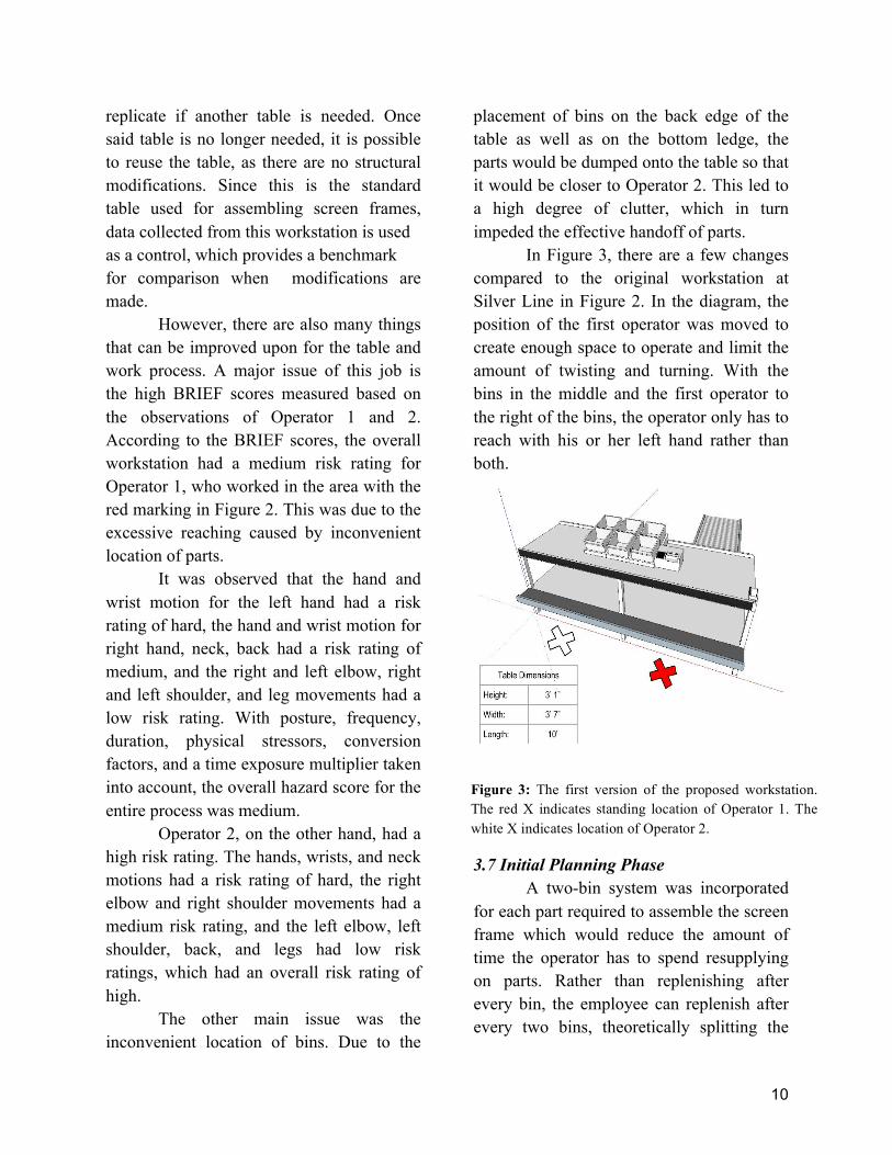
Figure 2: The original screen frame assembly workstation at the Silver Line. The red marker indicates where Operator 1 works, and the white marker indicates where Operator 2 works. The red X indicates standing location of Operator 1. The white X indicates location of Operator 2.
Figure 2.1: Dimensions of original screen frame workstation in inches.
10
replicate if another table is needed. Once said table is no longer needed, it is possible to reuse the table, as there are no structural modifications. Since this is the standard table used for assembling screen frames, data collected from this workstation is used as a control, which provides a benchmark for comparison when modifications are made.
However, there are also many things that can be improved upon for the table and work process. A major issue of this job is the high BRIEF scores measured based on the observations of Operator 1 and 2. According to the BRIEF scores, the overall workstation had a medium risk rating for Operator 1, who worked in the area with the red marking in Figure 2. This was due to the excessive reaching caused by inconvenient location of parts.
It was observed that the hand and wrist motion for the left hand had a risk rating of hard, the hand and wrist motion for right hand, neck, back had a risk rating of medium, and the right and left elbow, right and left shoulder, and leg movements had a low risk rating. With posture, frequency, duration, physical stressors, conversion factors, and a time exposure multiplier taken into account, the overall hazard score for the entire process was medium.
Operator 2, on the other hand, had a high risk rating. The hands, wrists, and neck motions had a risk rating of hard, the right elbow and right shoulder movements had a medium risk rating, and the left elbow, left shoulder, back, and legs had low risk ratings, which had an overall risk rating of high.
The other main issue was the inconvenient location of bins. Due to the
placement of bins on the back edge of the table as well as on the bottom ledge, the parts would be dumped onto the table so that it would be closer to Operator 2. This led to a high degree of clutter, which in turn impeded the effective handoff of parts.
In Figure 3, there are a few changes compared to the original workstation at Silver Line in Figure 2. In the diagram, the position of the first operator was moved to create enough space to operate and limit the amount of twisting and turning. With the bins in the middle and the first operator to the right of the bins, the operator only has to reach with his or her left hand rather than both.
3.7 Initial Planning Phase A two-bin system was incorporated
for each part required to assemble the screen frame which would reduce the amount of time the operator has to spend resupplying on parts. Rather than replenishing after every bin, the employee can replenish after every two bins, theoretically splitting the
Figure 3: The first version of the proposed workstation. The red X indicates standing location of Operator 1. The white X indicates location of Operator 2.

11
amount of time resupplying in half. Additionally, a label printer and dispenser were incorporated to reduce the amount of time spent on steps involving the identification label and the warning label. This step alone could remove a few seconds wasted on manually taking the label off the roll per frame part; If ten-thousand frame parts are labeled every day, then theoretically ten-thousand seconds, or nearly three hours per day, would be removed from the average time used in constructing the frames.
Figure 3 demonstrates different innovations that would further improve how well the operators perform, such as rubber matting on the bottom ledge of the workstation, cushioning on the front ledge of the table, and the alignment of the conveyor belt vertically with the table. The rubber matting prevents the frames from sliding. When the frames do not slide, the operators naturally remove the time used to realign the frame with the bottom ledge. Because the operators often lean over the table to reach for frame parts or use the edge of the table to guide them in putting the frame together, a cushion was included in order to reduce soft tissue compression, which is a factor used in determining the BRIEF score of a work operation.
Aligning the conveyer belt with the table limits the reaching prospect of the BRIEF score sheet when picking up pieces, and eliminates the need for the first operator to stand on the side of the table. The closer the operators are, without violating the space needed to work, the easier the operators can work with one another while the conveyor belt automatically places the frame parts on the table.
Drawbacks for this proposed design include insufficient space for larger sized frames because the printer blocks the drop-off location for parts exiting the conveyor belt. The current printer installed in the workstation only prints out the labels on the printer backing but does not remove or peel the labels while printing. Other stations of the Silver Line manufacturing company have a printer that automatically peels the labels, which is an aspect that can be implemented in the design. Peeling labels by hand is an intermediate step that wastes time and can be eliminated.
Furthermore, Operator 1, who utilizes metal clips, is still distant from bins. The position of needed materials is still inconvenient and causes excessive reaching, and the frame parts delivered by the conveyor belt are still too far away. Rearrangement of the materials in subsequent versions to follow could eliminate these disadvantages. 3.8 Version #2 (Proposed Design)
After further discussion, a proposal was constructed from the ideas crafted during the initial planning phase with Silver Line. Rather than having the conveyor belt only aligned with the table, the conveyor belt was also moved inwards to allow the frame parts to be delivered closer to Operator 1, as shown in Figure 4. The bins are also separated on the table to accommodate the pieces that both workers need, as Operator 1 uses only one type of corner bracket, and Operator 2 uses a different type of corner bracket as well as a metal clip. After finding the right device, a printer capable of printing the identification labels, as well as separating the label from

12
its backing, would reduce the cycle time of the frame because the operators no longer have to peel labels. The current methods of peeling and applying the labels are unsanitary. The manual label dispenser, designed to make labeling more efficient and sanitary, is placed on the right of the conveyor belt. This assist ultimately reduces the cycle time of frame labeling.
Most of the changes were implemented to reduce the BRIEF score. By allowing the conveyor belt to be integrated in the table, the parts would be closer to Operator 1, which means he or she will not have to reach as far, thus reducing the stress put on the elbow joint. The label printer allows Operator 1 to attach the identification label in an easier motion.
Functional flaws are present in the proposed design. The design in Figure 4 still does not allow sufficient space to construct the larger-sized frames that Silver Line produces. The printer is located to the conveyor belt’s immediate left, effectively blocking the length needed to accommodate frames of size 75 inches across.
Problems remain within the table itself. The upper ledge spans the full length of the table, which is unnecessary and restricting for Operator 1. Although Operator 2 needs the ledge for support, Operator 1 does not interact with the ledge, and its presence requires Operator 1 to reach farther to access the length and width bars, as well as labels and metal clips. The organization of supplies can still be made
Figure 4: The second version of the proposed workstation design at Silver Line.

13
more lean; extraneous bins present on the surface of the work table. 4. Results
Results indicate that a more ergonomically designed workspace increases efficiency and decreases physical stressors. By using changes in working methods and changes to the physical workstation, cycle times are projected to be 10.95% less and BRIEF scores are lowered for both operators.
4.1 Changes in Methods of Assembly In this design, the number of bins
needed to complete the frame was minimized after realizing that Operator 1 was the only operator installing the metal clips into one side of the frame along with the corner bracket. Operator 2 was
suggested to only install the corner brackets that did not require the metal clips, and put all bars of the frame together as the last step.
4.2 Changes to Workstation 4.2.1. Integration of Machinery
Since the redesigned table has the integrated conveyor belt, wheels were added to make the table mobile. Now when maintenance work needs to be done on the machine, the table will slide out to provide easy access to the worker.
4.2.2. Refilling Placing pre-prepared bins in the
actual workstation eliminates the need for employees to stop working and walk approximately 50 steps to refill their bins. Workers typically refill bins two to three times during their shift. Ensuring that the
Figure 5: Figure 5 demonstrates the final workstation. This model was used to create the actual workstation. It was used in comparing and contrasting BRIEF scores recorded before and after the changes.
14
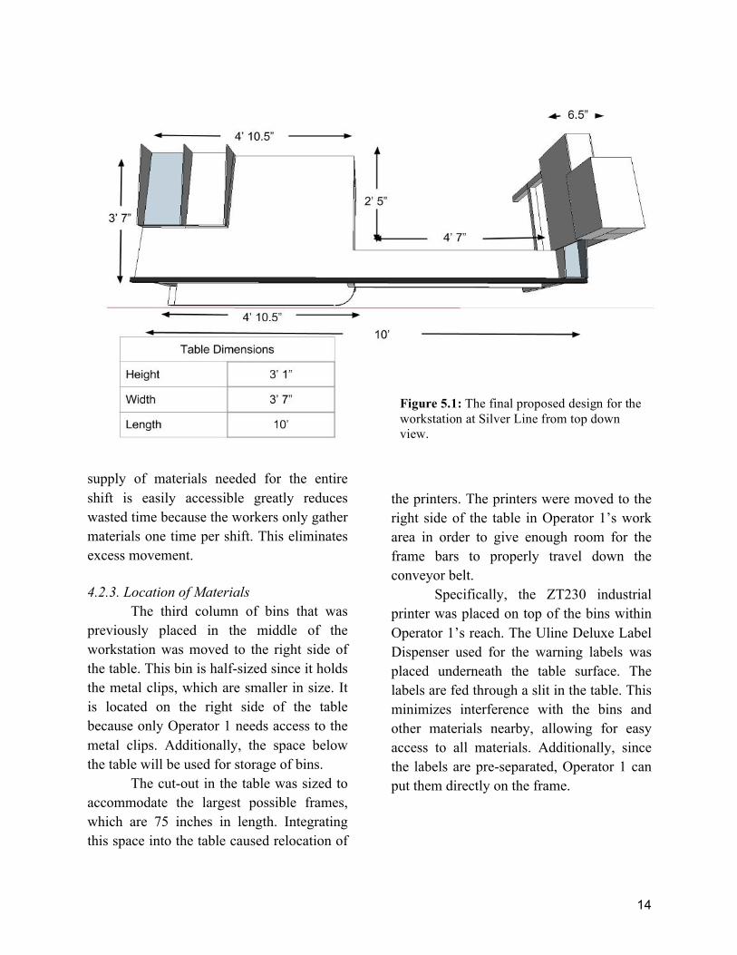
supply of materials needed for the entire shift is easily accessible greatly reduces wasted time because the workers only gather materials one time per shift. This eliminates excess movement. 4.2.3. Location of Materials
The third column of bins that was previously placed in the middle of the workstation was moved to the right side of the table. This bin is half-sized since it holds the metal clips, which are smaller in size. It is located on the right side of the table because only Operator 1 needs access to the metal clips. Additionally, the space below the table will be used for storage of bins.
The cut-out in the table was sized to accommodate the largest possible frames, which are 75 inches in length. Integrating this space into the table caused relocation of
the printers. The printers were moved to the right side of the table in Operator 1’s work area in order to give enough room for the frame bars to properly travel down the conveyor belt.
Specifically, the ZT230 industrial printer was placed on top of the bins within Operator 1’s reach. The Uline Deluxe Label Dispenser used for the warning labels was placed underneath the table surface. The labels are fed through a slit in the table. This minimizes interference with the bins and other materials nearby, allowing for easy access to all materials. Additionally, since the labels are pre-separated, Operator 1 can put them directly on the frame.
Figure 5.1: The final proposed design for the workstation at Silver Line from top down view.

15
4.2.4. BRIEF Score Reductions
The upper ledge was coated with cushioning to eliminate soft tissue compression for Operators 1 and 2. Soft tissue compressions occur when pressure is applied to areas of the body that have soft tissue. Leaning was the main source of soft tissue compression for the operators.
The bottom ledge was removed entirely on the right side of the table because it is unnecessary for the tasks Operator 1 must perform. Removing it allows Operator 1 to stand closer to the table and reach less. Operator 1, who picks up the bars and attaches the corner brackets with the metal clip, also experiences less forward leaning motions.
Modifications of the lower ledge were made to the left side. The lower ledge on the table was rounded off to prevent pain and injury. No sharp edges are exposed.
The redesigned table uses a sliding two-bin system on a ramp. The operators each have different heights and arm lengths, so the two-bin system was created to be mobile. They can be moved around on the surface of the workstation to fit the needs of the operator.
With all of the aforementioned improvements including the addition of cushioning and relocation of materials, bins, printers, and frame parts, the redesigned workstation effectively reduced BRIEF scores significantly for both workers.
Figure 6: Graph of BRIEF scores for original and proposed workstation.
Figure 6.1: Key for using hazard score to determine job priority.

16
Job hazard scores were calculated using by putting the BRIEF survey results through conversion factors and time multipliers. Theoretical deductions were made. The BRIEF score for Operator 1 decreases by 24.00% when soft tissue compression, back flexing and twisting, full extension of arms and elbows, and neck twisting are eliminated. The BRIEF score for Operator 2 is reduced by 11.76% when soft tissue compression, full extension of arms and elbows, and neck twisting are eliminated.
4.2.5. Improving Efficiency Refill time was reduced by cutting
back on refills from three per shift to one per shift. Elimination of the refill step saves 51 seconds: the total time to walk from the workstation to the supply boxes, refill the bin, and then return to the workstation.
Cycle times were reduced by changing the location of materials. A more effective printer and the introduction of a warning label dispenser reduce the time. Calculations for motion time savings indicated a conservative reduction of 3.51 seconds and a projected reduction of 5.40 seconds. The projected cycle time 10.95% less than the original.
Figure 7: Overall cycle time is reduced. Conservative saving of 3.51 seconds. Projected saving of 5.40 seconds. Conservative measures are 65% of the projection.

17
4.6. Cost Analysis
Printers that automatically peel labels are costly but efficient. A new printer was purchased for the labels that peel the bar codes. The $855 cost for the bar code printer was justified by improved cycle times. The warning labels did not require a printer. A dispenser that automatically removes and peels the labels off the paper backing was used for the warning label. The dispenser cost $67 and was justified by improved cycle times.
The cost-benefit analysis was calculated on Excel using a formula designed by Human Tech. Savings per unit were converted to annual savings by multiplying over the duration of one year. A work day was counted as three shifts of eight hours each, and work weeks are five days per week.
Benefits reaped from implementing changes justify the cost of making changes. The $922 cost required to update the workstation is justified by the increased screen frame production rate. The projected payback period is 0.06 years and the conservative payback period is 0.09 years conservative, which approximates to one month.
If the proposed workstation were to be used in Silver Line for the duration of
one week, workers would theoretically make 870 more frames per week than they do at the current station. Expanded to a year, workers would make 45,353 more frames per year. 5. Conclusion
Industrial engineering is geared towards the optimization of systems. As hypothesized, the redesigned workstation would decrease cycle times and reduce BRIEF scores. The proposed work process and station is designed to be more ergonomic and cost-effective. The redesigned workstation meets the criteria for a more favorable work environment. If implemented, this process would both reduce strenuous motions for the operators and yield financial profit for Silver Line.
The research focuses on the first three elements of the 5S process. The last components of 5S, which translate roughly to “standardize” and “sustain” are left to Silver Line to pursue. This project creates a theoretical station that is more ergonomic, but its success remains in its implementation. Methods used in the redesigned workstation can be used in more stations in Silver Line on a larger scale.

18
6. Discussion While the research did meet the
objective, there are more ways to improve the work environment. It is always possible to further streamline the production process.
One aspect of the design remains unimproved: the motions and hammering that Operator 2 must do to complete the frame. Technology and machinery can be used to alleviate physical stressors. The team drafted the design, seen in Figure 8, for a clamp-like device specifically suited to the frames that would address this problem. Corner pieces would be inserted, followed by frame components, then assembled drawing the pieces together by use of a lever. Due to time constraints, the assembly process was unable to be completed. As a result, hand motions remain repetitive as hammering is not eliminated.
This device would eliminate the need for workers to hammer to corner brackets in
by hand. Due to the tight fit of the frame, the device would have to be built with extreme accuracy so as not to produce poorly-fit frames. If completed and properly sized, this device, when used as intended, would improve speed and avoid soft tissue compression for Operator 2. BRIEF scores would theoretically be reduced further with this mechanism. Another potential improvement that was left out of the final design was a height adjustable table. A table lift crank would allow the workers to raise or lower the table since the workers are all of different heights. By adjusting the table to meet personal comfort, reaches would be more natural and the process would become more ergonomic.
However, the operators are not necessarily of similar height. Consequently, a table could be adjusted to benefit one worker but disadvantage the other. One possible solution would be to split the table
Figure 8: A design of the planned mechanism
19
so each operator could adjust half the table to their own height, but this interferes with handoff of uncompleted frames from Operator 1 to Operator 2, and also interferes with the printer and conveyor. While it would be theoretically optimal for both workers to have their work space adjusted to their heights, it is difficult and cumbersome in practice. Acknowledgements
The authors would like to sincerely
thank the directors of the Governor’s School program, Dean Antoine, Dean Rosen, as well as the Residential Teaching Assistant of the project, Taylor Au, who provided valuable advice and suggestions as the work progressed.
Additionally, the authors would like to thank the mentors of this project, Brian Garcia, Wanda Duran, Adam Luthin, and Phil Shrider who provided knowledge on Silver Line operations and gave helpful feedback on the team’s designs, and Jose Alvarado who constructed the workstation. Thank you also to the Silver Line company for allowing the team to have firsthand insight of assembly operations on the working floor and for generously providing transportation.
Thank you to the GSET staff, as well as the various sponsors of the program: the State of New Jersey, Rutgers University, Rutgers School of Engineering, Silver Line by Andersen, Lockheed Martin, South Jersey Industries, Novo Nordisk Pharmaceuticals, and NJ Resources, who made it possible for the authors to have this experience.
References 1 “The Silver Line Story: Our Commitment,” Silver Line by Andersen, 2014, http://www.silverlinewindows.com/silver-line-vinyl-windows, (14 July 2015). 2 “Andersen Corporation to Purchase Silver Line Building Products,” Business Wire, May 24, 2006, http://www.businesswire.com/news/home/20060524005564/en/Andersen-Corporation-Purchase-Silver-Line-Building-Products#.VZ8gwMZViko, (14 July 2015). 3 National Health Service UK, “Repetitive Strain Injury,” National Health Service, 17 December 2013, http://www.nhs.uk/conditions/Repetitive-strain-injury/Pages/Introduction.aspx, (16 July 2015). 4 “What is 5S: Seiri, Seiton, Seiso, Seiketsu, Shitsuke,” Lean Manufacturing Tools, 2015, http://leanmanufacturingtools.org/192/what-is-5s-seiri-seiton-seiso-seiketsu-shitsuke/, (15 July 2015). 5 Team, “Lean Thinking and Methods,” United States Environmental Protection Agency, 19 February 2015, http://www.epa.gov/lean/environment/methods/fives.htm, (15 July 2015). 6American National Standards Institute, Inc., “Ergonomic Guidelines for the Design, Installation and Use of Machine Tools,” ANSI Technical Report, April 1994 (15 July 2015).
7 Leankaizen Limited, “How to Balance Your Process Using Takt Time and Cycle
20
Time,” Leankaizen, 2014, http://www.leankaizen.co.uk/takt-time-vs-cycle-time.html, (15 July 2015).
8 “Value-Add vs Non-Value Adding Processes,” Lean Manufacturing Tools, 2015, http://leanmanufacturingtools.org/89/value-add-vs-non-value- adding-processes, (15 July 2015 9 Humantech Inc., “Handbook of Ergonomic Design Guidelines,” Humantech, 2012, (15 July 2015). 10Systems2Win, “Muda -- 7 Types of Waste,” Systems 2 Win: Continuously Improving Tools For Continuous Improvement, 2015, http://www.systems2win.com/LK/lean /7wastes.htm, (15 July 2015) 11Illinois Manufacturing Excellence Center, “Solutions Source: Eliminate Non-Value Added Effort Through Lean Manufacturing,” IMEC, 2015, http://www.imec.org/SS-Eliminate-Non-Value-Added-Effort.cfm, (15 July 2015).
12 Michelle Safrit, “Basics of the Two-Bin Kanban System,” Falcon Fastening Solutions, 2015,
http://falconfastening.com/lean-learning/inventory-management/basics-of-the-two-bin- kanban-system, (15 July 2015).
13 Gwendolyn D. Galsworth, “The Visual Workplace: Do You Speak Excellence?,” Quality Digest, 05 August 2010, http://www.qualitydigest.com/inside/twitter-ed/visual-workplace.html, (15 July 2015). 14American Academy of Orthopedic Surgeons, “Soft Tissue Injuries,” Ortho Info, July 2007, http://orthoinfo.aaos.org/topic.cfm?topic=A00304, (16 July 2015).
15 Occupational Safety and Health Administration, “Muscle and Joint Problems from Awkward Postures and Repetitive Motions,” United States Department of Labor, 2015, https://www.osha.gov/SLTC/nailsalons/musclestrains.html, (17 July 2015).
16 Paul Haney, “Rubber Friction,” Inside Racing Technology, 27 January 2004, http://insideracingtechnology.com/tirebkexerpt1.htm, (17 July 2015).