6 a jun2004
DESCRIPTION
API 6ATRANSCRIPT
and
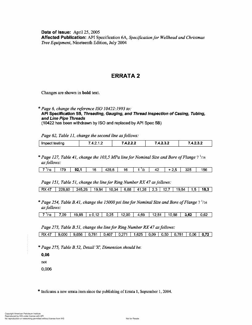
6,
127, 41, 103,5 and 7
151, 51,
254, and 7
273,
275,
0,006
a 1 1 2004.
Copyright American Petroleum Institute
Reproduced by IHS under license with API
Not for ResaleNo reproduction or networking permitted without license from IHS
--`,,`,`,-`-`,,`,,`,`,,`---
Copyright American Petroleum Institute
Reproduced by IHS under license with API
Not for ResaleNo reproduction or networking permitted without license from IHS
--`,,`,`,-`-`,,`,,`,`,,`---
Specification for Wellhead andChristmas Tree Equipment
ANSI/API Specification 6ANineteenth Edition, July 2004
ISO 10423:2003, {Modified} Petroleum and naturalgas industries-Drilling and productionequipment-Wellhead and Christmas treeequipment
EFFECTIVE DATE: FEBRUARY 1, 2005
ANSI/API 6A1IS0 10423-2003
ERRATA 1, SEPTEMBER 1, 2004
~- _ ._ -_ -
~ISO]~
- - ._ -_ --~-- .
Specification for Wellhead and Christmas Tree Equipment
ANSI/API Specification 6A Nineteenth Edition, July 2004
ISO 10423:2003, {Modified} Petroleum and natural gas industries-Drilling and production equipment-Wellhead and Christmas tree equipment
EFFECTIVE DATE: FEBRUARY 1, 2005
ANSI/API 6A1IS0 10423-2003
ERRATA 1, SEPTEMBER 1, 2004
-~-- -- -- -
~ISO] -~-- -- -- --~-
.A.merican PetroleUll1 Institute
Heiping You ~t1'lleJcb
~e~l",j

Copyright American Petroleum Institute
Reproduced by IHS under license with API
Not for ResaleNo reproduction or networking permitted without license from IHS
--`,,`,`,-`-`,,`,,`,`,,`---
Copyright American Petroleum Institute
Reproduced by IHS under license with API
Not for ResaleNo reproduction or networking permitted without license from IHS
--`,,`,`,-`-`,,`,,`,`,,`---
Copyright American Petroleum Institute
Reproduced by IHS under license with API
Not for ResaleNo reproduction or networking permitted without license from IHS
--`,,`,`,-`-`,,`,,`,`,,`---
Copyright American Petroleum Institute
Reproduced by IHS under license with API
Not for ResaleNo reproduction or networking permitted without license from IHS
--`,,`,`,-`-`,,`,,`,`,,`---
Copyright American Petroleum Institute
Reproduced by IHS under license with API
Not for ResaleNo reproduction or networking permitted without license from IHS
--`,,`,`,-`-`,,`,,`,`,,`---
API Specification 6A / ISO 10423
7 QUALITY CONTROL 577.1 General 577.2 Measuring and testing equipment 577.3 Quality control personnel qualifications 587.4 Quality control requirements 587.5 Quality control records requirements 95
8 EQUIPMENT MARKING 1008.1 Marking requirements 1008.2 Wellhead equipment 1028.3 Connectors and fittings 1028.4 Casing and tubing hangers 1028.5 Valves and chokes 1038.6 Loose connectors [flanged, threaded, other end connectors (OEC) and welded] 1048.7 Other equipment 1048.8 Studs and nuts 1058.9 Christmas trees 1058.10 Valve-removal plugs 1058.11 Bullplugs 1058.12 Back-pressure valves 106
9 STORING AND SHIPPING 1069.1 Draining after testing 1069.2 Rust prevention 1069.3 Sealing surface protection 1069.4 Assembly and maintenance instructions 1069.5 Ring gaskets 1069.6 Age control of non-metallic materials 106
10 EQUIPMENT-SPECIFIC REQUIREMENTS 10710.1 Flanged end and outlet connections 10710.2 Threaded end and outlet connections 14010.3 Studs and nuts 14610.4 Ring gaskets 14810.5 Valves 15410.6 Casing and tubing heads 16910.7 Casing and tubing hangers 17410.8 Tubing-head adapters 17910.9 Chokes 18110.10 Tees and crosses 18410.11 Test and gauge connections for 103,5 MPa and 138,0 MPa (15 000 psi and 20000 psi)
equipment 18910.12 Fluid sampling devices 18910.13 Christmas trees 19210.14 Cross-over connectors 19210.15 Adapter and spacer spools 19710.16 Actuators 19810.17 Lock screws, alignment pins and retainer screw packing mechanisms 20210.18 Other end connectors (OECs) 20310.19 Top connectors 20410.20 Surface and underwater safety valves and actuators for offshore service 20510.21 Bullplugs 21010.22 Valve-removal plugs 21310.23 Other pressure-boundary penetrations 21310.24 Back-pressure valves 214
iv
API Specification 6A / ISO 10423
7 QUALITY CONTROL ............................................................................................................................ 57 7.1 General ........................................................................................................................................ 57 7.2 Measuring and testing equipment ................................................................................................ 57 7.3 Quality control personnel qualifications ....................................................................................... 58 7.4 Quality control requirements ........................................................................................................ 58 7.5 Quality control records requirements ........................................................................................... 95
8 EQUIPMENT MARKING ..................................................................................................................... 100 8.1 Marking requirements ................................................................................................................ 100 8.2 Wellhead equipment .................................................................................................................. 102 8.3 Connectors and fittings .............................................................................................................. 102 8.4 Casing and tubing hangers ........................................................................................................ 102 8.5 Valves and chokes ..................................................................................................................... 103 8.6 Loose connectors [flanged, threaded, other end connectors (OEC) and welded] ..................... 104 8.7 Other equipment ........................................................................................................................ 104 8.8 Studs and nuts ........................................................................................................................... 105 8.9 Christmas trees .......................................................................................................................... 105 8.10 Valve-removal plugs ................................................................................................................... 105 8.11 Bullplugs ..................................................................................................................................... 105 8.12 Back-pressure valves ................................................................................................................. 106
9 STORING AND SHIPPING ................................................................................................................. 106 9.1 Draining after testing .................................................................................................................. 106 9.2 Rust prevention .......................................................................................................................... 106 9.3 Sealing surface protection .......................................................................................................... 106 9.4 Assembly and maintenance instructions .................................................................................... 106 9.5 Ring gaskets .............................................................................................................................. 106 9.6 Age control of non-metallic materials ......................................................................................... 106
10 EQUIPMENT-SPECIFIC REQUIREMENTS ....................................................................................... 107 10.1 Flanged end and outlet connections ....................................................................................... 107 10.2 Threaded end and outlet connections ..................................................................................... 140 10.3 Studs and nuts ........................................................................................................................ 146 10.4 Ring gaskets ........................................................................................................................... 148 10.5 Valves ..................................................................................................................................... 154 10.6 Casing and tubing heads ........................................................................................................ 169 10.7 Casing and tubing hangers ..................................................................................................... 174 10.8 Tubing-head adapters ............................................................................................................. 179 10.9 Chokes .................................................................................................................................... 181 10.10 Tees and crosses .................................................................................................................... 184 10.11 Test and gauge connections for 103,5 MPa and 138,0 MPa (15 000 psi and 20000 psi)
equipment ............................................................................................................................... 189 10.12 Fluid sampling devices ............................................................................................................ 189 10.13 Christmas trees ....................................................................................................................... 192 10.14 Cross-over connectors ............................................................................................................ 192 10.15 Adapter and spacer spools ..................................................................................................... 197 10.16 Actuators ................................................................................................................................. 198 10.17 Lock screws, alignment pins and retainer screw packing mechanisms .................................. 202 10.18 Other end connectors (OECs) ................................................................................................. 203 10.19 Top connectors ....................................................................................................................... 204 10.20 Surface and underwater safety valves and actuators for offshore service ............................... 205 10.21 Bullplugs .................................................................................................................................. 210 10.22 Valve-removal plugs ................................................................................................................ 213 10.23 Other pressure-boundary penetrations ................................................................................... 213 10.24 Back-pressure valves .............................................................................................................. 214
iv
Copyright American Petroleum Institute
Reproduced by IHS under license with API
Not for ResaleNo reproduction or networking permitted without license from IHS
--`,,`,`,-`-`,,`,,`,`,,`---
API Specification 6A / ISO 10423
11 REPAIR AND REMANUFACTURE 214
ANNEX A (informative) Purchasing guidelines 215
ANNEX B (informative) US Customary unit tables and data for this International Standard 234
ANNEX C (informative) Method of calculating stud bolt lengths for type 6B and 6BX flanges 289
ANNEX D (informative) Recommended flange bolt torque 291
ANNEX E (informative) Recommended weld groove design dimensions 295
ANNEX F (informative) Performance verification procedures 299
ANNEX G (informative) Design and rating of equipment for use at elevated temperatures 333
ANNEX H (normative) Design and manufacture of surface wellhead running, retrieving and testingtools, clean-out tools and wear bushings 336
ANNEX I (normative) Performance verification procedures for surface safety valves and underwatersafety valves 341
ANNEX J WITHDRAWN 349
ANNEX K (informative) Recommended specifications for top connectors for christmas trees 362
ANNEX L (normative) Specifications for valve-removal preparations and valve-removal plugs 377
ANNEX M (informative) List of tables and figures 393
ANNEX N (informative) API Monogram and test agency licensing 403
ANNEX 0 (normative) API Regional annex 404
Bibliography 412
v
API Specification 6A / ISO 10423
11 REPAIR AND REMANUFACTURE .................................................................................................... 214
ANNEX A (informative) Purchasing guidelines ......................................................................................... 215
ANNEX B (informative) US Customary unit tables and data for this International Standard .................... 234
ANNEX C (informative) Method of calculating stud bolt lengths for type 6B and 6BX flanges ................. 289
ANNEX D (informative) Recommended flange bolt torque ....................................................................... 291
ANNEX E (informative) Recommended weld groove design dimensions ................................................. 295
ANNEX F (informative) Performance verification procedures ................................................................... 299
ANNEX G (informative) Design and rating of equipment for use at elevated temperatures ..................... 333
ANNEX H (normative) Design and manufacture of surface wellhead running, retrieving and testing tools, clean-out tools and wear bushings .................................................................................................. 336
ANNEX I (normative) Performance verification procedures for surface safety valves and underwater safety valves .............................................................................................................................. ............... 341
ANNEX J WITHDRAWN ................................................................................................................... 349
ANNEX K (informative) Recommended specifications for top connectors for christmas trees ................. 362
ANNEX L (normative) Specifications for valve-removal preparations and valve-removal plugs ............... 377
ANNEX M (informative) List of tables and figures ..................................................................................... 393
ANNEX N (informative) API Monogram and test agency licensing ............................................................. 403
ANNEX 0 (normative) API Regional annex ................................................................................................ 404
Bibliography .............................................................................................................................................. 412
v
Copyright American Petroleum Institute
Reproduced by IHS under license with API
Not for ResaleNo reproduction or networking permitted without license from IHS
--`,,`,`,-`-`,,`,,`,`,,`---
Copyright American Petroleum Institute
Reproduced by IHS under license with API
Not for ResaleNo reproduction or networking permitted without license from IHS
--`,,`,`,-`-`,,`,,`,`,,`---

Copyright American Petroleum Institute
Reproduced by IHS under license with API
Not for ResaleNo reproduction or networking permitted without license from IHS
--`,,`,`,-`-`,,`,,`,`,,`---
Copyright American Petroleum Institute
Reproduced by IHS under license with API
Not for ResaleNo reproduction or networking permitted without license from IHS
--`,,`,`,-`-`,,`,,`,`,,`---
API Specification 6A / ISO 10423
Petroleum and natural gas industries - Drilling and productionequipment - Wellhead and christmas tree equipment
1 Scope
1.1 Purpose
This International Standard specifies requirements and gives recommendations for the performance, dimensionaland functional interchangeability, design, materials, testing, inspection, welding, marking, handling, storing,shipment, purchasing, repair and remanufacture of wellhead and christmas tree equipment for use in the petroleumand natural gas industries.
This International Standard does not apply to field use, field testing or field repair of wellhead and christmas treeequipment.
1.2 Applicability
This International Standard is applicable to the following specific equipment.
a) Wellhead equipment:
casing head housings;
casing head spools;
tubing head spools;
cross-over spools;
multi-stage head housings and spools.
b) Connectors and fittings:
cross-over connectors;
tubing head adapters;
top connectors;
tees and crosses;
fluid-sampling devices;
adapter and spacer spools.
c) Casing and tubing hangers:
- mandrel hangers;
1
API Specification 6A / ISO 10423
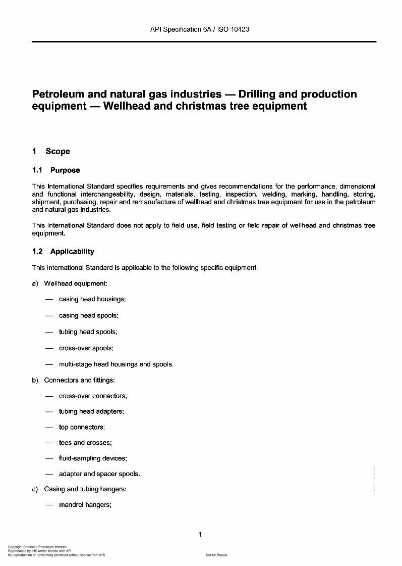
Petroleum and natural gas industries - Drilling and production equipment - Wellhead and christmas tree equipment
1 Scope
1.1 Purpose
This International Standard specifies requirements and gives recommendations for the performance, dimensional and functional interchangeability, design, materials, testing, inspection, welding, marking, handling, storing, shipment, purchasing, repair and remanufacture of wellhead and christmas tree equipment for use in the petroleum and natural gas industries.
This International Standard does not apply to field use, field testing or field repair of wellhead and christmas tree equipment.
1.2 Applicability
This International Standard is applicable to the following specific equipment.
a) Wellhead equipment:
casing head housings;
casing head spools;
tubing head spools;
cross-over spools;
multi-stage head housings and spools.
b) Connectors and fittings:
cross-over connectors;
tubing head adapters;
top connectors;
tees and crosses;
fluid-sampling devices;
adapter and spacer spools.
c) Casing and tubing hangers:
- mandrel hangers;
1
Copyright American Petroleum Institute
Reproduced by IHS under license with API
Not for ResaleNo reproduction or networking permitted without license from IHS
--`,,`,`,-`-`,,`,,`,`,,`---
API Specification 6A / ISO 10423
- slip hangers.
d) Valves and chokes:
single valves;
multiple valves;
actuated valves;
valves prepared for actuators;
check valves;
chokes;
surface and underwater safety valves and actuators;
back-pressure valves.
e) Loose connectors [flanged, threaded, other end connectors (OEC), and welded]:
weld neck connectors;
blind connectors;
threaded connectors;
adapter and spacer connectors;
bullplugs;
valve-removal plugs.
f) Other equipment:
actuators;
hubs;
pressure boundary penetrations;
ring gaskets;
running and testing tools (in Annex H);
wear bushings (in Annex H).
The nomenclature used in this International Standard for typical equipment is shown in Figure 1 and Figure 2. Allparts whose physical dimensions conform to the metric tables incorporated into the body of this InternationalStandard or to the US Customary units tables in Annex B are acceptable (see Introduction).
1.3 Service conditions
This International Standard defines service conditions, in terms of pressure, temperature and material class for thewell-bore constituents, and operating conditions.
2
API Specification 6A / ISO 10423
- slip hangers.
d) Valves and chokes:
single valves;
multiple valves;
actuated valves;
valves prepared for actuators;
check valves;
chokes;
surface and underwater safety valves and actuators;
back-pressure valves.
e) Loose connectors [flanged, threaded, other end connectors (OEC), and welded]:
weld neck connectors;
blind connectors;
threaded connectors;
adapter and spacer connectors;
bullplugs;
valve-removal plugs.
f) Other equipment:
actuators;
hubs;
pressure boundary penetrations;
ring gaskets;
running and testing tools (in Annex H);
wear bushings (in Annex H).
The nomenclature used in this International Standard for typical equipment is shown in Figure 1 and Figure 2. All parts whose physical dimensions conform to the metric tables incorporated into the body of this International Standard or to the US Customary units tables in Annex B are acceptable (see Introduction).
1.3 Service conditions
This International Standard defines service conditions, in terms of pressure, temperature and material class for the well-bore constituents, and operating conditions.
2
3
Copyright American Petroleum Institute
Reproduced by IHS under license with API
Not for ResaleNo reproduction or networking permitted without license from IHS
--`,,`,`,-`-`,,`,,`,`,,`---
API Specification 6A / ISO 10423
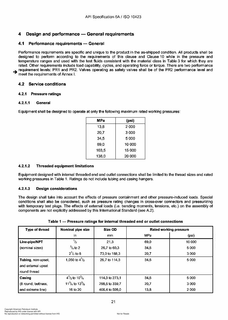
1.4 Product specification levels (PSL)
This International Standard establishes requirements for five product specification levels. These five PSLdesignations define different levels of technical quality requirements. Annex A provides guidelines (notrequirements) for selecting an acceptable PSL.
20 22
4
1415161118
19
,~ 3
45
~~ 6"'d-'-----1
_---8---_9
,.1IllL(I~rD~====10I 11.tJ----12i'Iti---13
1-~~
Key
1 back-pressure valve preparation
2 subsurface safety valve control line
3 subsurface safety valve control line outlet
4 tubing head adapter
5 lock screw
6 tubing hanger pack-off
7 extended neck tubing hanger with downhole safety valve control line
8 studded side outlet
9 valve removal preparation
10 bottom casing pack-off
11 tubing head spool
12 double studded adapter
13 annular casing pack-off
14 casing hanger (slip style)
15 threaded outlet connection
16 bullplug
17 casing head housing
18 surface casing
19 wellhead support plate
20 tubing pack-off retainer
21 tubing hanger (slip style)
22 tubing
Figure 1 - Typical wellhead assembly nomenclature
3
API Specification 6A / ISO 10423
1.4 Product specification levels (PSL)
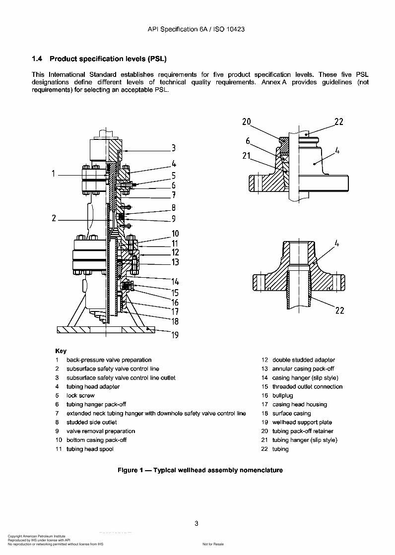
This International Standard establishes requirements for five product specification levels. These five PSL designations define different levels of technical quality requirements. Annex A provides guidelines (not requirements) for selecting an acceptable PSL.
~ ______ 3
4
1-~~~~ 5 ~~=-_6
2 ----++---+rH
Key
N-'-----1
_---8 ---_9
10 ~~ __ 11 ~1-__ 12
~o7I:IfJf--__ 13
14 15 16 11 18
19
1 back-pressure valve preparation
2
3
subsurface safety valve control line
subsurface safety valve control line outlet
4 tubing head adapter
5 lock screw
6 tubing hanger pack-off
7 extended neck tubing hanger with downhole safety valve control line
8 studded side outlet
9 valve removal preparation
10 bottom casing pack-off
11 tubing head spool
2
12 double studded adapter
13 annular casing pack-off
14 casing hanger (slip style)
15 threaded outlet connection
16 bullplug
17 casing head housing
18 surface casing
19 wellhead support plate
20 tubing pack-off retainer
21 tubing hanger (slip style)
22 tubing
Figure 1 - Typical wellhead assembly nomenclature
3
Copyright American Petroleum Institute
Reproduced by IHS under license with API
Not for ResaleNo reproduction or networking permitted without license from IHS
--`,,`,`,-`-`,,`,,`,`,,`---
API Specification 6A / ISO 10423
24251 26
23 2122101328293031 51032131415161118
4
21
11
34
22
Key
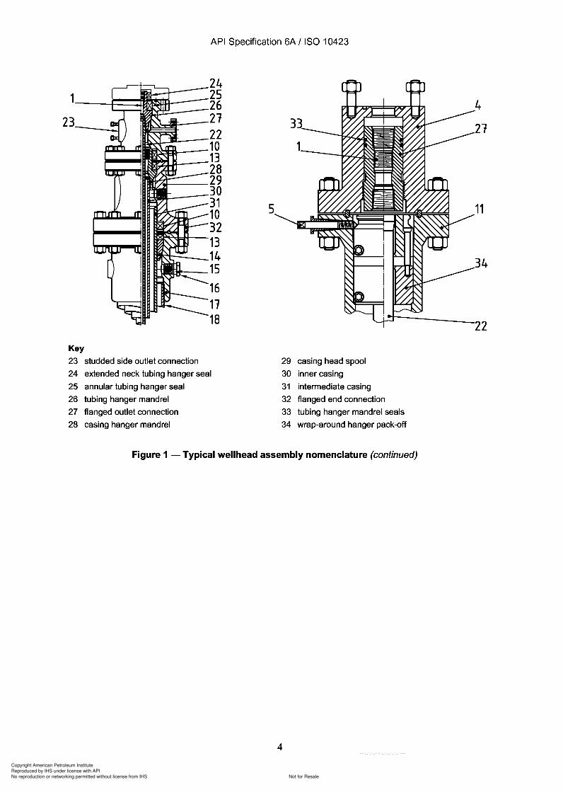
23 studded side outlet connection
24 extended neck tubing hanger seal
25 annular tubing hanger seal
26 tubing hanger mandrel
27 flanged outlet connection
28 casing hanger mandrel
29 casing head spool
30 inner casing
31 intermediate casing
32 flanged end connection
33 tubing hanger mandrel seals
34 wrap-around hanger pack-off
Figure 1 - Typical wellhead assembly nomenclature (continued)
4
2
API Specification 6A / ISO 10423
Key
24 25 26
~j:..--_21
I~~ 22 ~m-__ 10
~:;&..R-__ 13 28
/eI-__ 29 ~_30
31 10 32
~_--..I11II ~~1::H--13
~:---14
.JoIo--_15
16 11 18
23 studded side outlet connection
24 extended neck tubing hanger seal
25 annular tubing hanger seal
26 tubing hanger mandrel
27 flanged outlet connection
28 casing hanger mandrel
5
3
29 casing head spool
30 inner casing
31 intermediate casing
32 flanged end connection
33 tubing hanger mandrel seals
34 wrap-around hanger pack-off
Figure 1 - Typical wellhead assembly nomenclature (continued)
4
Copyright American Petroleum Institute
Reproduced by IHS under license with API
Not for ResaleNo reproduction or networking permitted without license from IHS
--`,,`,`,-`-`,,`,,`,`,,`---
1
API Specification 6A / ISO 10423
1
2
3
4
5
6
8 9
10
11
Key
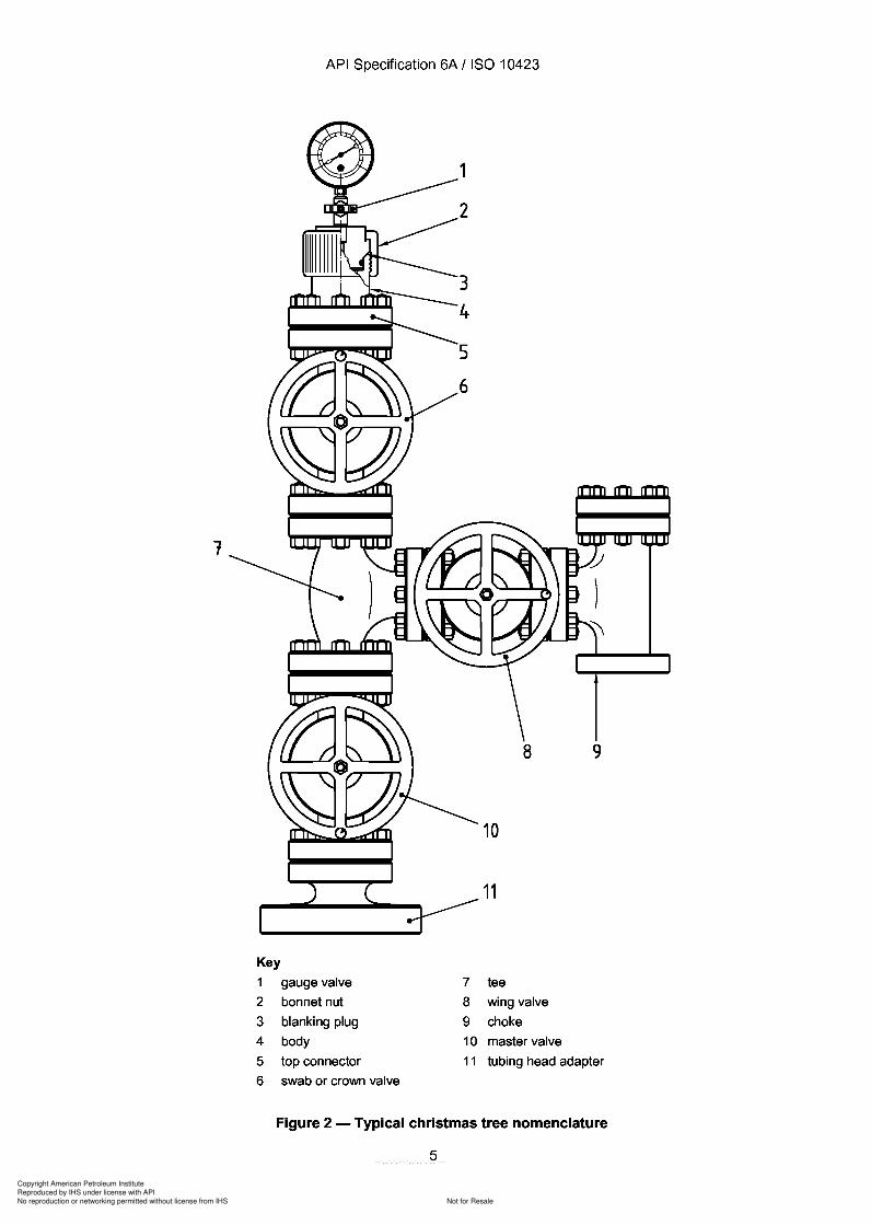
1 gauge valve
2 bonnet nut
3 blanking plug
4 body
5 top connector
6 swab or crown valve
7 tee
8 wing valve
9 choke
10 master valve
11 tubing head adapter
Figure 2 - Typical christmas tree nomenclature
5
1
Key
1
2
3 4
5 6
API Specification 6A / ISO 10423
gauge valve
bonnet nut
blanking plug
body
top connector
swab or crown valve
1
2
3
4
5
6
7
8
9 10
11
8 9
10
11
tee
wing valve
choke
master valve
tubing head adapter
Figure 2 - Typical christmas tree nomenclature
5
Copyright American Petroleum Institute
Reproduced by IHS under license with API
Not for ResaleNo reproduction or networking permitted without license from IHS
--`,,`,`,-`-`,,`,,`,`,,`---
API Specification 6A / ISO 10423
2 Normative references
The following referenced documents are indispensable for the application of this document. For dated references,-+ only the edition cited applies. For undated references, the latest edition of the referenced document (including any
amendments) applies.
ISO 2859-1:1999, Sampling procedures for inspection by attributes - Part 1: Sampling schemes indexed byacceptance quality limit (AQL) for lot-by-Iot inspection
ISO 10414-1, Petroleum and natural gas industries - Field testing of drilling fluids - Part 1: Water-based fluids
ISO 10422:1993, Petroleum and natural gas industries - Threading, gauging, and thread inspection of casing,tubing and line pipe threads - Specification
ISO 11960, Petroleum and natural gas industries - Steel pipes for use as casing or tubing for wells
ISO 13533, Petroleum and natural gas industries -Drilling and production equipment -Drill-through equipment
ISO 13628-4, Petroleum and natural gas industries - Design and operation of subsea production systems Part 4: Subsea wellhead and tree equipment
ISO 13678, Petroleum and natural gas industries - Evaluation and testing of thread compounds for use withcasing, tubing and line pipe
API1) Spec 7:1997, Specification for rotary drill stem elements
API RP 14F, Recommended practice for design and installation of electrical systems for fixed and floating offshorepetroleum production facilities for unclassified and class 1, division 1 and division 2 locations
ASME2) B1.1, Unified inch screw threads
ASME B1.2, Gages and gaging for unified inch screw threads
ASME B1.20.1, Pipe threads, general purpose (inch)
ASME Boiler and Pressure Vessel Code:1998, Section V, Non destructive examination
ASME Boiler and Pressure Vessel Code:1998, Section VIII, Division 1, Rules for construction ofpressure vessels
ASME Boiler and Pressure Vessel Code:1998, Section VIII, Division 2, Alternative rules for construction ofpressurevessels
ASME Boiler and Pressure Vessel Code:1998, Section IX, Welding and brazing qualifications
ASNT3) SNT-TC-1A, Personnel qualifications and certification in non destructive testing
ASTM4) A 193/A 193M, Standard Specification for Alloy-Steel and Stainless Steel Bolting Materials for HighTemperature Service
1) American Petroleum Institute, 1220 L Street North West, Washington, D.C. 20005, USA.
2) ASME International, 345 East 47th Street, New York, NY 10017-2392, USA.
3) American Society for Non destructive Testing, 4153 Arlingate Plaza, Columbus, OH 43228-0518, USA.
4) American Society for Testing and Materials, 100 Barr Harbor Drive, West Conshohoken, PA 19428-2959, USA.
6
API Specification 6A / ISO 10423
2 Normative references
The following referenced documents are indispensable for the application of this document. For dated references, -+ only the edition cited applies. For undated references, the latest edition of the referenced document (including any
amendments) applies.
ISO 2859-1:1999, Sampling procedures for inspection by attributes - Part 1: Sampling schemes indexed by acceptance quality limit (AQL) for lot-by-Iot inspection
ISO 10414-1, Petroleum and natural gas industries - Field testing of drilling fluids - Part 1: Water-based fluids
ISO 10422:1993, Petroleum and natural gas industries - Threading, gauging, and thread inspection of casing, tubing and line pipe threads - Specification
ISO 11960, Petroleum and natural gas industries - Steel pipes for use as casing or tubing for wells
ISO 13533, Petroleum and natural gas industries -Drilling and production equipment -Drill-through equipment
ISO 13628-4, Petroleum and natural gas industries - Design and operation of subsea production systems -Part 4: Subsea wellhead and tree equipment
ISO 13678, Petroleum and natural gas industries - Evaluation and testing of thread compounds for use with casing, tubing and line pipe
API1) Spec 7:1997, Specification for rotary drill stem elements
API RP 14F, Recommended practice for design and installation of electrical systems for fixed and floating offshore petroleum production facilities for unclassified and class 1, division 1 and division 2 locations
ASME2) B1.1, Unified inch screw threads
ASME B1.2, Gages and gaging for unified inch screw threads
ASME B1.20.1, Pipe threads, general purpose (inch)
ASME Boiler and Pressure Vessel Code:1998, Section V, Non destructive examination
ASME Boiler and Pressure Vessel Code: 1998, Section VIII, Division 1, Rules for construction of pressure vessels
ASME Boiler and Pressure Vessel Code:1998, Section VIII, Division 2, Alternative rules for construction of pressure vessels
ASME Boiler and Pressure Vessel Code:1998, Section IX, Welding and brazing qualifications
ASNT3) SNT-TC-1A, Personnel qualifications and certification in non destructive testing
ASTM4) A 193/A 193M, Standard Specification for Alloy-Steel and Stainless Steel Bolting Materials for HighTemperature Service
1) American Petroleum Institute, 1220 L Street North West, Washington, D.C. 20005, USA.
2) ASME International, 345 East 47th Street, New York, NY 10017-2392, USA.
3) American Society for Non destructive Testing, 4153 Arlingate Plaza, Columbus, OH 43228-0518, USA.
4) American Society for Testing and Materials, 100 Barr Harbor Drive, West Conshohoken, PA 19428-2959, USA.
6
Copyright American Petroleum Institute
Reproduced by IHS under license with API
Not for ResaleNo reproduction or networking permitted without license from IHS
--`,,`,`,-`-`,,`,,`,`,,`---

Copyright American Petroleum Institute
Reproduced by IHS under license with API
Not for ResaleNo reproduction or networking permitted without license from IHS
--`,,`,`,-`-`,,`,,`,`,,`---
Copyright American Petroleum Institute
Reproduced by IHS under license with API
Not for ResaleNo reproduction or networking permitted without license from IHS
--`,,`,`,-`-`,,`,,`,`,,`---
Copyright American Petroleum Institute
Reproduced by IHS under license with API
Not for ResaleNo reproduction or networking permitted without license from IHS
--`,,`,`,-`-`,,`,,`,`,,`---
Copyright American Petroleum Institute
Reproduced by IHS under license with API
Not for ResaleNo reproduction or networking permitted without license from IHS
--`,,`,`,-`-`,,`,,`,`,,`---
API Specification 6A / ISO 10423
3.1.33cross-over connectoradapter with a restricted-area sealing means and with a top-connection pressure rating above that of the lowerconnection
3.1.34cross-over flangedouble- or single-studded adapter flange with a restricted-area sealing means and with a top-connection pressurerating above that of the lower connection
3.1.35cross-over spoolflanged or other connected equipment with a restricted-area sealing means, at or near the face of its lower flange
NOTE Cross-over spools are also provided with suitable means to suspend and seal around an inner string of casing ortubing. A cross-over spool has a top connection with a pressure rating above that of the lower connection.
3.1.36date of manufacturedate of manufacturer's final acceptance of finished equipment
3.1.37date of repair/remanufacturedate of repairer's/remanufacturer's final acceptance of finished equipment
3.1.38dynamic sealseal in which motion exists relative to the sealing surface after installation
3.1.39end connectionoutlet connectionintegral male or female thread; hub end connector and flange, studded or through-bolted, or any other means usedto join together equipment that contains or controls pressure
3.1.40equipmentany item or assembled equipment to which this International Standard is applicable
3.1.41equivalent roundERstandard for comparing various shaped sections to round bars, in determining the response to hardeningcharacteristics when heat-treating low alloy and martensitic corrosion-resistant steel
3.1.42fitgeometric relationship between parts
NOTE This includes the tolerance criteria used during the design of a part and its mating part.
3.1.43flangeprotruding rim with holes to accept bolts and having a sealing mechanism used to join pressure-containingequipment, with dimensions specified in this International Standard
3.1.43.1blind flangeflange with no centre bore, used to close off completely a flanged end or outlet connection
11
API Specification 6A I ISO 10423
3.1.33 cross-over connector adapter with a restricted-area sealing means and with a top-connection pressure rating above that of the lower connection
3.1.34 cross-over flange double- or single-studded adapter flange with a restricted-area sealing means and with a top-connection pressure rating above that of the lower connection
3.1.35 cross-over spool flanged or other connected equipment with a restricted-area sealing means, at or near the face of its lower flange
NOTE Cross-over spools are also provided with suitable means to suspend and seal around an inner string of casing or tubing. A cross-over spool has a top connection with a pressure rating above that of the lower connection.
3.1.36 date of manufacture date of manufacturer's final acceptance of finished equipment
3.1.37 date of repair/remanufacture date of repairer's/remanufacturer's final acceptance of finished equipment
3.1.38 dynamic seal seal in which motion exists relative to the sealing surface after installation
3.1.39 end connection outlet connection integral male or female thread; hub end connector and flange, studded or through-bolted, or any other means used to join together equipment that contains or controls pressure
3.1.40 equipment any item or assembled equipment to which this International Standard is applicable
3.1.41 equivalent round ER standard for comparing various shaped sections to round bars, in determining the response to hardening characteristics when heat-treating low alloy and martensitic corrosion-resistant steel
3.1.42 fit geometric relationship between parts
NOTE This includes the tolerance criteria used during the design of a part and its mating part.
3.1.43 flange protruding rim with holes to accept bolts and having a sealing mechanism used to join pressure-containing equipment, with dimensions specified in this International Standard
3.1.43.1 blind flange flange with no centre bore, used to close off completely a flanged end or outlet connection
11
Copyright American Petroleum Institute
Reproduced by IHS under license with API
Not for ResaleNo reproduction or networking permitted without license from IHS
--`,,`,`,-`-`,,`,,`,`,,`---
Copyright American Petroleum Institute
Reproduced by IHS under license with API
Not for ResaleNo reproduction or networking permitted without license from IHS
--`,,`,`,-`-`,,`,,`,`,,`---
Copyright American Petroleum Institute
Reproduced by IHS under license with API
Not for ResaleNo reproduction or networking permitted without license from IHS
--`,,`,`,-`-`,,`,,`,`,,`---
API Specification 6A / ISO 10423
3.1.64make-and-break, verbconnect and disconnect a connection
3.1.65manufacturing operationactivity involving, but not limited to, the machining, welding, heat treating or other processes utilized to produce afinished product
3.1.66material performance basiscapabilities which must be demonstrated, as a minimum, for material to satisfy the criteria of this InternationalStandard
3.1.67multistage cross-over spoolflanged or other connected equipment with more than one restricted-area sealing means to provide suitablecapability to suspend and seal around multiple inner strings of casing or tubing at several stages
NOTE A multistage cross-over spool may have a top connector with a pressure rating above that of the lower connector.
3.1.68objective evidencedocumented field experience, test data, publications, finite element analysis or calculations that verify performancecharacteristics, as applicable
3.1.69partindividual piece used in the assembly of single equipment units
EXAMPLES Body, bonnet, gate, stud, handwheel, etc., are parts of a valve. A part may also be a piece not in finished form.
3.1.70post-weld heat treatmentany heat treatment subsequent to welding, including stress relief
3.1.71pressure-boundary penetrationdevice which penetrates directly into or communicates with the wellbore and is not defined elsewhere in thisInternational Standard
EXAMPLES Grease or sealant injection fitting; check valve; control, test or gauge port plug and fitting, needle valve on test,gauge or injection port; electric and control line penetration.
3.1.72pressure-containing partpart whose failure to function as intended would result in a release of retained fluid to the atmosphere
EXAMPLES Bodies, bonnets and stems.
3.1.73pressure-controlling partpart intended to control or regulate the movement of pressurized fluids
EXAMPLES Valve bore sealing mechanisms, choke trim and hangers.
3.1.74pressure integritystructural and leak-resistant capability of a product to contain applied pressure
14
3.1.64 make-and-break, verb connect and disconnect a connection
3.1.65 manufacturing operation
API Specification 6A / ISO 10423
activity involving, but not limited to, the machining, welding, heat treating or other processes utilized to produce a finished product
3.1.66 material performance basis capabilities which must be demonstrated, as a minimum, for material to satisfy the criteria of this International Standard
3.1.67 multistage cross-over spool flanged or other connected equipment with more than one restricted-area sealing means to provide suitable capability to suspend and seal around multiple inner strings of casing or tubing at several stages
NOTE A multistage cross-over spool may have a top connector with a pressure rating above that of the lower connector.
3.1.68 objective evidence documented field experience, test data, publications, finite element analysis or calculations that verify performance characteristics, as applicable
3.1.69 part individual piece used in the assembly of single equipment units
EXAMPLES Body, bonnet, gate, stud, handwheel, etc., are parts of a valve. A part may also be a piece not in finished form.
3.1.70 post-weld heat treatment any heat treatment subsequent to welding, including stress relief
3.1.71 pressure-boundary penetration device which penetrates directly into or communicates with the wellbore and is not defined elsewhere in this International Standard
EXAMPLES Grease or sealant injection fitting; check valve; control, test or gauge port plug and fitting, needle valve on test, gauge or injection port; electric and control line penetration.
3.1.72 pressure-containing part part whose failure to function as intended would result in a release of retained fluid to the atmosphere
EXAMPLES Bodies, bonnets and stems.
3.1.73 pressure-controlling part part intended to control or regulate the movement of pressurized fluids
EXAMPLES Valve bore sealing mechanisms, choke trim and hangers.
3.1.74 pressure integrity structural and leak-resistant capability of a product to contain applied pressure
14
Copyright American Petroleum Institute
Reproduced by IHS under license with API
Not for ResaleNo reproduction or networking permitted without license from IHS
--`,,`,`,-`-`,,`,,`,`,,`---
Copyright American Petroleum Institute
Reproduced by IHS under license with API
Not for ResaleNo reproduction or networking permitted without license from IHS
--`,,`,`,-`-`,,`,,`,`,,`---
API Specification 6A / ISO 10423
3.1.86restricted-area sealing meansrestricted-area pack-offpackoff or other device used to isolate an area at higher pressure from one at lower pressure
NOTE This device serves to limit pressure-induced loads on connectors or areas of a lower pressure rating. It may also bea seal which encloses a pressure-containment area smaller than the adjacent ring gasket or connector seal.
3.1.87retained fluidactual fluid produced by a well or injected into a well
3.1.88room temperatureany temperature between 4 °C and 50°C (40 of and 120 OF)
3.1.89rounded indicationsurface NDE indication which is circular or elliptical, having a length less than 3 times its width
3.1.90running tooltool used to run, retrieve, position or connect wellhead equipment remotely from the drill floor
3.1.91secondary equipmentpiece of equipment that can normally be isolated from the well fluid or well pressure
3.1.92serializationassignment of a unique code to individual parts and/or pieces of equipment to maintain records
3.1.93spacerpressure-containing piece of equipment used to connect and provide separation between other pieces ofequipment
3.1.94specified materialmaterial meeting a particular performance requirement(s) as specified by a manufacturer or industry standard
3.1.95stainless steelsteel containing more than 11 % chromium (mass fraction) to render the steel corrosion-resistant
NOTE Other elements may be added to secure special properties.
3.1.96static sealseal in which no motion exists relative to sealing surfaces after installation
3.1.97stress-corrosion crackingcracking which results from a combination of corrosion and stress
3.1.98stress reliefcontrolled heating of material to a predetermined temperature for the purpose of reducing any residual stressesafter welding
16
3.1.86 restricted-area sealing means restricted-area pack-off
API Specification 6A / ISO 10423
packoff or other device used to isolate an area at higher pressure from one at lower pressure
NOTE This device serves to limit pressure-induced loads on connectors or areas of a lower pressure rating. It may also be a seal which encloses a pressure-containment area smaller than the adjacent ring gasket or connector seal.
3.1.87 retained fluid actual fluid produced by a well or injected into a well
3.1.88 room temperature any temperature between 4 °C and 50°C (40 of and 120 OF)
3.1.89 rounded indication surface NDE indication which is circular or elliptical, having a length less than 3 times its width
3.1.90 running tool tool used to run, retrieve, position or connect wellhead equipment remotely from the drill floor
3.1.91 secondary equipment piece of equipment that can normally be isolated from the well fluid or well pressure
3.1.92 serialization assignment of a unique code to individual parts and/or pieces of equipment to maintain records
3.1.93 spacer pressure-containing piece of equipment used to connect and provide separation between other pieces of equipment
3.1.94 specified material material meeting a particular performance requirement(s) as specified by a manufacturer or industry standard
3.1.95 stainless steel steel containing more than 11 % chromium (mass fraction) to render the steel corrosion-resistant
NOTE Other elements may be added to secure special properties.
3.1.96 static seal seal in which no motion exists relative to sealing surfaces after installation
3.1.97 stress-corrosion cracking cracking which results from a combination of corrosion and stress
3.1.98 stress relief controlled heating of material to a predetermined temperature for the purpose of reducing any residual stresses after welding
16
Copyright American Petroleum Institute
Reproduced by IHS under license with API
Not for ResaleNo reproduction or networking permitted without license from IHS
--`,,`,`,-`-`,,`,,`,`,,`---
API Specification 6A / ISO 10423
3.1.99studded-flange connectionflanged end or outlet connection in which thread-anchored studs screwed into tapped holes replace the holes forbolt studs
3.1.100substantive changechange identified by the manufacturer which affects the performance of the product in the intended service
3.1.101sulfide-stress crackingcracking of metallic materials due to exposure to fluid containing hydrogen sulfide
3.1.102surface safety valveSSVautomatic wellhead valve assembly which closes upon loss of power supply
NOTE Where used in this International Standard, the term is understood to include an SSV valve and SSVactuator.
3.1.103SSV actuatorunderwater safety valve actuatorUSV actuatordevice which causes the SSV/USV valve to open when power is supplied and to close automatically when power islost or released
3.1.104SSVvalveUSVvalveportion of the SSV/USV which contains the wellstream and shuts off flow when closed
3.1.105teepressure-containing fitting with three openings
NOTE Two openings opposite one another form the run portion of the tee, and one opening is at 90° to the line of the run.Tees may be equipped with threads, flanges, studs or other end connectors.
-+3.1.106test tooltool used to run into the wellhead in order to perform a pressure test
3.1.107top connectorbottom hole test adapteruppermost fitting of a christmas tree which allows full-bore access to the christmas tree
3.1.108thread protectorcap or insert used to protect threads and seals during handling, transportation and storage
3.1.109tubingpipe placed within a well to conduct fluid from the well's producing formation into the christmas tree or to conductkill or treatment fluids in a well
NOTE Tubing is distinguished from casing as being retrievable during the life of the well.
17
-+
API Specification 6A / ISO 10423
3.1.99 studded-flange connection flanged end or outlet connection in which thread-anchored studs screwed into tapped holes replace the holes for bolt studs
3.1.100 substantive change change identified by the manufacturer which affects the performance of the product in the intended service
3.1.101 sulfide-stress cracking cracking of metallic materials due to exposure to fluid containing hydrogen sulfide
3.1.102 surface safety valve SSV automatic wellhead valve assembly which closes upon loss of power supply
NOTE Where used in this International Standard, the term is understood to include an SSV valve and SSVactuator.
3.1.103 SSV actuator underwater safety valve actuator USV actuator device which causes the SSV/USV valve to open when power is supplied and to close automatically when power is lost or released
3.1.104 SSVvalve USVvalve portion of the SSV/USV which contains the wellstream and shuts off flow when closed
3.1.105 tee pressure-containing fitting with three openings
NOTE Two openings opposite one another form the run portion of the tee, and one opening is at 90° to the line of the run. Tees may be equipped with threads, flanges, studs or other end connectors.
3.1.106 test tool tool used to run into the wellhead in order to perform a pressure test
3.1.107 top connector bottom hole test adapter uppermost fitting of a christmas tree which allows full-bore access to the christmas tree
3.1.108 thread protector cap or insert used to protect threads and seals during handling, transportation and storage
3.1.109 tubing pipe placed within a well to conduct fluid from the well's producing formation into the christmas tree or to conduct kill or treatment fluids in a well
NOTE Tubing is distinguished from casing as being retrievable during the life of the well.
17
Copyright American Petroleum Institute
Reproduced by IHS under license with API
Not for ResaleNo reproduction or networking permitted without license from IHS
--`,,`,`,-`-`,,`,,`,`,,`---
Copyright American Petroleum Institute
Reproduced by IHS under license with API
Not for ResaleNo reproduction or networking permitted without license from IHS
--`,,`,`,-`-`,,`,,`,`,,`---
Copyright American Petroleum Institute
Reproduced by IHS under license with API
Not for ResaleNo reproduction or networking permitted without license from IHS
--`,,`,`,-`-`,,`,,`,`,,`---
Copyright American Petroleum Institute
Reproduced by IHS under license with API
Not for ResaleNo reproduction or networking permitted without license from IHS
--`,,`,`,-`-`,,`,,`,`,,`---
Copyright American Petroleum Institute
Reproduced by IHS under license with API
Not for ResaleNo reproduction or networking permitted without license from IHS
--`,,`,`,-`-`,,`,,`,`,,`---
API Specification 6A / ISO 10423
4.2.2 Temperature ratings
4.2.2.1 General
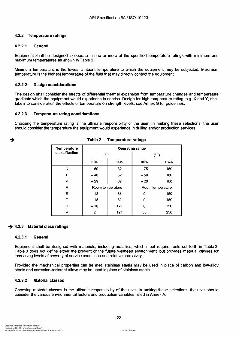
Equipment shall be designed to operate in one or more of the specified temperature ratings with minimum andmaximum temperatures as shown in Table 2.
Minimum temperature is the lowest ambient temperature to which the equipment may be subjected. Maximumtemperature is the highest temperature of the fluid that may directly contact the equipment.
4.2.2.2 Design considerations
The design shall consider the effects of differential thermal expansion from temperature changes and temperaturegradients which the equipment would experience in service. Design for high temperature rating, e.g. X and Y, shalltake into consideration the effects of temperature on strength levels, see Annex G for guidelines.
4.2.2.3 Temperature rating considerations
Choosing the temperature rating is the ultimate responsibility of the user. In making these selections, the usershould consider the temperature the equipment would experience in drilling and/or production services.
Table 2 - Temperature ratings
Temperature Operating rangeclassification
°C CF)
min. max. min. max.
K -60 82 -75 180
L -46 82 -50 180
P -29 82 -20 180
R Room temperature Room temperature
S -18 66 0 150
T -18 82 0 180
U -18 121 0 250
V 2 121 35 250
-+ 4.2.3 Material class ratings
4.2.3.1 General
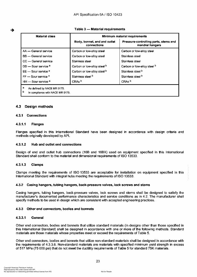
Equipment shall be designed with materials, including metallics, which meet requirements set forth in Table 3.Table 3 does not define either the present or the future wellhead environment, but provides material classes forincreasing levels of severity of service conditions and relative corrosivity.
Provided the mechanical properties can be met, stainless steels may be used in place of carbon and low-alloysteels and corrosion-resistant alloys may be used in place of stainless steels.
4.2.3.2 Material classes
Choosing material classes is the ultimate responsibility of the user. In making these selections, the user shouldconsider the various environmental factors and production variables listed in Annex A.
22
API Specification 6A / ISO 10423
4.2.2 Temperature ratings
4.2.2.1 General
Equipment shall be designed to operate in one or more of the specified temperature ratings with minimum and maximum temperatures as shown in Table 2.
Minimum temperature is the lowest ambient temperature to which the equipment may be subjected. Maximum temperature is the highest temperature of the fluid that may directly contact the equipment.
4.2.2.2 Design considerations
The design shall consider the effects of differential thermal expansion from temperature changes and temperature gradients which the equipment would experience in service. Design for high temperature rating, e.g. X and Y, shall take into consideration the effects of temperature on strength levels, see Annex G for guidelines.
4.2.2.3 Temperature rating considerations
Choosing the temperature rating is the ultimate responsibility of the user. In making these selections, the user should consider the temperature the equipment would experience in drilling and/or production services.
Table 2 - Temperature ratings
Temperature Operating range classification
°C CF)
min. max. min. max.
K -60 82 -75 180
L -46 82 -50 180
P -29 82 -20 180
R Room temperature Room temperature
S -18 66 0 150
T -18 82 0 180
U -18 121 0 250
V 2 121 35 250
-+ 4.2.3 Material class ratings
4.2.3.1 General
Equipment shall be designed with materials, including metallics, which meet requirements set forth in Table 3. Table 3 does not define either the present or the future wellhead environment, but provides material classes for increasing levels of severity of service conditions and relative corrosivity.
Provided the mechanical properties can be met, stainless steels may be used in place of carbon and low-alloy steels and corrosion-resistant alloys may be used in place of stainless steels.
4.2.3.2 Material classes
Choosing material classes is the ultimate responsibility of the user. In making these selections, the user should consider the various environmental factors and production variables listed in Annex A.
22
Copyright American Petroleum Institute
Reproduced by IHS under license with API
Not for ResaleNo reproduction or networking permitted without license from IHS
--`,,`,`,-`-`,,`,,`,`,,`---
Copyright American Petroleum Institute
Reproduced by IHS under license with API
Not for ResaleNo reproduction or networking permitted without license from IHS
--`,,`,`,-`-`,,`,,`,`,,`---
API Specification 6A / ISO 10423
In the event stress levels calculated by the methods in 4.3.3.2 to 4.3.3.6 exceed the allowable stresses, othermethods identified by the manufacturer shall be used to justify these stresses. Fatigue analysis and localizedbearing stress values are beyond the scope of this International Standard.
4.3.3.2 ASME method
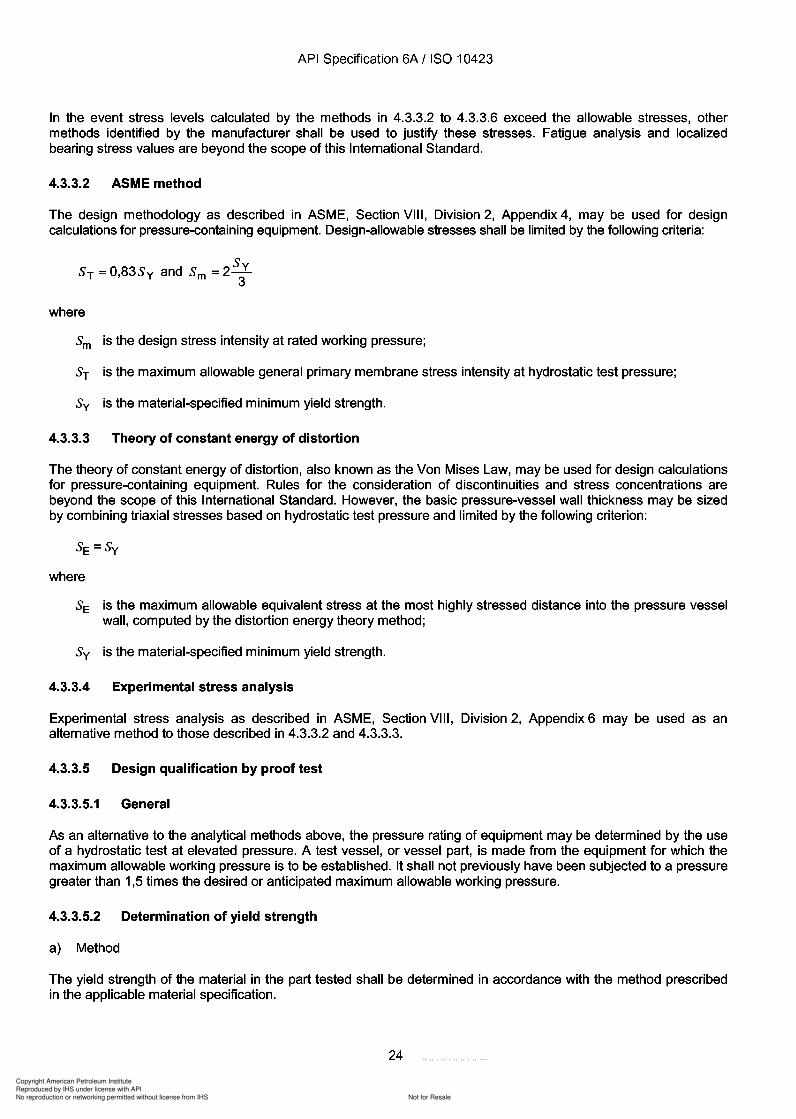
The design methodology as described in ASME, Section VIII, Division 2, Appendix 4, may be used for designcalculations for pressure-containing equipment. Design-allowable stresses shall be limited by the following criteria:
SyST =0,83Sy and Sm =23
where
Sm is the design stress intensity at rated working pressure;
ST is the maximum allowable general primary membrane stress intensity at hydrostatic test pressure;
Sy is the material-specified minimum yield strength.
4.3.3.3 Theory of constant energy of distortion
The theory of constant energy of distortion, also known as the Von Mises Law, may be used for design calculationsfor pressure-containing equipment. Rules for the consideration of discontinuities and stress concentrations arebeyond the scope of this International Standard. However, the basic pressure-vessel wall thickness may be sizedby combining triaxial stresses based on hydrostatic test pressure and limited by the following criterion:
where
SE is the maximum allowable equivalent stress at the most highly stressed distance into the pressure vesselwall, computed by the distortion energy theory method;
Sy is the material-specified minimum yield strength.
4.3.3.4 Experimental stress analysis
Experimental stress analysis as described in ASME, Section VIII, Division 2, Appendix 6 may be used as analternative method to those described in 4.3.3.2 and 4.3.3.3.
4.3.3.5 Design qualification by proof test
4.3.3.5.1 General
As an alternative to the analytical methods above, the pressure rating of equipment may be determined by the useof a hydrostatic test at elevated pressure. A test vessel, or vessel part, is made from the equipment for which themaximum allowable working pressure is to be established. It shall not previously have been subjected to a pressuregreater than 1,5 times the desired or anticipated maximum allowable working pressure.
4.3.3.5.2 Determination of yield strength
a) Method
The yield strength of the material in the part tested shall be determined in accordance with the method prescribedin the applicable material specification.
24
API Specification 6A / ISO 10423
In the event stress levels calculated by the methods in 4.3.3.2 to 4.3.3.6 exceed the allowable stresses, other methods identified by the manufacturer shall be used to justify these stresses. Fatigue analysis and localized bearing stress values are beyond the scope of this International Standard.
4.3.3.2 ASME method
The design methodology as described in ASME, Section VIII, Division 2, Appendix 4, may be used for design calculations for pressure-containing equipment. Design-allowable stresses shall be limited by the following criteria:
Sy ST = 0,83Sy and Sm = 23
where
Sm is the design stress intensity at rated working pressure;
ST is the maximum allowable general primary membrane stress intensity at hydrostatic test pressure;
Sy is the material-specified minimum yield strength.
4.3.3.3 Theory of constant energy of distortion
The theory of constant energy of distortion, also known as the Von Mises Law, may be used for design calculations for pressure-containing equipment. Rules for the consideration of discontinuities and stress concentrations are beyond the scope of this International Standard. However, the basic pressure-vessel wall thickness may be sized by combining triaxial stresses based on hydrostatic test pressure and limited by the following criterion:
where
SE is the maximum allowable equivalent stress at the most highly stressed distance into the pressure vessel wall, computed by the distortion energy theory method;
Sy is the material-specified minimum yield strength.
4.3.3.4 Experimental stress analysis
Experimental stress analysis as described in ASME, Section VIII, Division 2, Appendix 6 may be used as an alternative method to those described in 4.3.3.2 and 4.3.3.3.
4.3.3.5 Design qualification by proof test
4.3.3.5.1 General
As an alternative to the analytical methods above, the pressure rating of equipment may be determined by the use of a hydrostatic test at elevated pressure. A test vessel, or vessel part, is made from the equipment for which the maximum allowable working pressure is to be established. It shall not previously have been subjected to a pressure greater than 1,5 times the desired or anticipated maximum allowable working pressure.
4.3.3.5.2 Determination of yield strength
a) Method
The yield strength of the material in the part tested shall be determined in accordance with the method prescribed in the applicable material specification.
24
Copyright American Petroleum Institute
Reproduced by IHS under license with API
Not for ResaleNo reproduction or networking permitted without license from IHS
--`,,`,`,-`-`,,`,,`,`,,`---
API Specification 6A / ISO 10423
b) Specimen preparation
Yield strength so determined shall be the average from three or four specimens cut from the part tested after thetest is completed. The specimens shall be cut from a location where the stress during the test has not exceededthe yield strength. The specimens shall not be flame-cut because this might affect the strength of the material.
c) Alternative specimens
If excess stock from the same piece of material is available and has been given the same heat treatment as thepressure part, the test specimens may be cut from this excess stock. The specimen shall not be removed by flamecutting or any other method involving sufficient heat to affect the properties of the specimen.
d) Exemption
If yield strength is not determined by test specimens, an alternative method is given in 4.3.3.5.3 for evaluation ofproof test results to establish the maximum allowable working pressure.
4.3.3.5.3 Test procedure
a) Instrumentation
Measure strains in the direction of the maximum stress as close as practical to the most highly stressed locationsby means of strain gauges of any type capable of indicating strains to 50 microstrain (0,005 %) (0,000 05 in/in). Themanufacturer shall document the procedure used to determine the location or locations at which strain is to bemeasured, and the means to compensate for temperature and hydrostatic pressure imposed on the gauges.
b) Application of pressure
Gradually increase the hydrostatic pressure in the vessel or vessel part, until approximately one-half the anticipatedworking pressure is reached. Thereafter, increase the test pressure in steps of approximately one-tenth or less ofthe rated working pressure until the pressure required by the test procedure is reached.
c) Observations
After each increment of pressure has been applied, take and record readings of the strain gauges and thehydrostatic pressure. Then release the pressure and determine any permanent strain at each gauge after anypressure increment that indicates an increase in strain for this increment over the previous equal pressureincrement. Only one application of each increment of pressure is required.
d) Records
Plot two curves of strain against test pressure for each gauge line as the test progresses, one showing the strainunder pressure and one showing the permanent strain when the pressure is removed. The test may bediscontinued when the test pressure reaches the value H which will, by the formula, justify the desired workingpressure, but shall not exceed the pressure at which the plotted points for the most highly strained gauge line reach0,2 % strain.
e) Resulting rating
Compute the maximum allowable working pressure p for parts tested under this subclause by one of the followingequations.
If the average yield strength is determined in accordance with 4.3.3.5.2:
25
API Specification 6A / ISO 10423
b) Specimen preparation
Yield strength so determined shall be the average from three or four specimens cut from the part tested after the test is completed. The specimens shall be cut from a location where the stress during the test has not exceeded the yield strength. The specimens shall not be flame-cut because this might affect the strength of the material.
c) Alternative specimens
If excess stock from the same piece of material is available and has been given the same heat treatment as the pressure part, the test specimens may be cut from this excess stock. The specimen shall not be removed by flame cutting or any other method involving sufficient heat to affect the properties of the specimen.
d) Exemption
If yield strength is not determined by test specimens, an alternative method is given in 4.3.3.5.3 for evaluation of proof test results to establish the maximum allowable working pressure.
4.3.3.5.3 Test procedure
a) Instrumentation
Measure strains in the direction of the maximum stress as close as practical to the most highly stressed locations by means of strain gauges of any type capable of indicating strains to 50 microstrain (0,005 %) (0,000 05 in/in). The manufacturer shall document the procedure used to determine the location or locations at which strain is to be measured, and the means to compensate for temperature and hydrostatic pressure imposed on the gauges.
b) Application of pressure
Gradually increase the hydrostatic pressure in the vessel or vessel part, until approximately one-half the anticipated working pressure is reached. Thereafter, increase the test pressure in steps of approximately one-tenth or less of the rated working pressure until the pressure required by the test procedure is reached.
c) Observations
After each increment of pressure has been applied, take and record readings of the strain gauges and the hydrostatic pressure. Then release the pressure and determine any permanent strain at each gauge after any pressure increment that indicates an increase in strain for this increment over the previous equal pressure increment. Only one application of each increment of pressure is required.
d) Records
Plot two curves of strain against test pressure for each gauge line as the test progresses, one showing the strain under pressure and one showing the permanent strain when the pressure is removed. The test may be discontinued when the test pressure reaches the value H which will, by the formula, justify the desired working pressure, but shall not exceed the pressure at which the plotted pOints for the most highly strained gauge line reach 0,2 % strain.
e) Resulting rating
Compute the maximum allowable working pressure p for parts tested under this subclause by one of the following equations.
If the average yield strength is determined in accordance with 4.3.3.5.2:
25
p
Copyright American Petroleum Institute
Reproduced by IHS under license with API
Not for ResaleNo reproduction or networking permitted without license from IHS
--`,,`,`,-`-`,,`,,`,`,,`---
API Specification 6A / ISO 10423
If the actual average yield strength is not determined by test specimens:
p=O,4H
where
H is the hydrostatic test pressure at which this test was stopped, in accordance with 4.3.3.5.3 b);
Sy is the material-specified minimum yield strength;
SA is the actual average yield strength from test specimens.
4.3.3.6 Non-standard materials design requirements
The design methodology as described in ASME, Section VIII, Division 2, Appendix 4, shall be used for design andcalculations for pressure-containing equipment utilizing non-standard materials. Design allowable stresses shall belimited by the following criteria:
Ss =the smaller of 2 Sy or R m, min.
where
Sm is the design stress intensity at rated working pressure;
Ss is the maximum combined primary and secondary stress intensity;
ST is the maximum allowable general primary membrane stress intensity at hydrostatic test pressure;
R m min is the material-specified minimum ultimate tensile strength;, .
Sy is the material-specified minimum yield strength.
4.3.4 Closure bolting
The maximum allowable tensile stress for closure bolting shall be determined considering initial bolt-up, ratedworking pressure and hydrostatic test pressure conditions. Bolting stresses, based on the root area of the thread,shall not exceed the following limit:
SA =0,83Sy
where
SA is the maximum allowable tensile stress;
Sy is the bolting material-specified minimum yield strength.
Bolting stresses shall be determined considering all loading on the closure, including pressure acting over the sealarea, gasket loads and any additional mechanical and thermal loads.
4.3.5 Other parts
All other pressure-containing parts and all pressure-controlling parts shall be designed to satisfy the manufacturer'sdocumented performance characteristics and the service conditions in 4.2. The manufacturer shall specify methodsto be used in design which are consistent with accepted engineering practices.
26
API Specification 6A / ISO 10423
If the actual average yield strength is not determined by test specimens:
p=O,4H
where
H is the hydrostatic test pressure at which this test was stopped, in accordance with 4.3.3.5.3 b);
Sy is the material-specified minimum yield strength;
SA is the actual average yield strength from test specimens.
4.3.3.6 Non-standard materials design requirements
The design methodology as described in ASME, Section VIII, Division 2, Appendix 4, shall be used for design and calculations for pressure-containing equipment utilizing non-standard materials. Design allowable stresses shall be limited by the following criteria:
Ss = the smaller of 2 Sy or R m, min.
where
Sm is the design stress intensity at rated working pressure;
Ss is the maximum combined primary and secondary stress intensity;
ST is the maximum allowable general primary membrane stress intensity at hydrostatic test pressure;
Rm min is the material-specified minimum ultimate tensile strength; , .
Sy is the material-specified minimum yield strength.
4.3.4 Closure bolting
The maximum allowable tensile stress for closure bolting shall be determined considering initial bolt-up, rated working pressure and hydrostatic test pressure conditions. Bolting stresses, based on the root area of the thread, shall not exceed the following limit:
SA = 0,83Sy
where
SA is the maximum allowable tensile stress;
Sy is the bolting material-specified minimum yield strength.
Bolting stresses shall be determined considering all loading on the closure, including pressure acting over the seal area, gasket loads and any additional mechanical and thermal loads.
4.3.5 Other parts
All other pressure-containing parts and all pressure-controlling parts shall be designed to satisfy the manufacturer's documented performance characteristics and the service conditions in 4.2. The manufacturer shall specify methods to be used in design which are consistent with accepted engineering practices.
26
Copyright American Petroleum Institute
Reproduced by IHS under license with API
Not for ResaleNo reproduction or networking permitted without license from IHS
--`,,`,`,-`-`,,`,,`,`,,`---
Copyright American Petroleum Institute
Reproduced by IHS under license with API
Not for ResaleNo reproduction or networking permitted without license from IHS
--`,,`,`,-`-`,,`,,`,`,,`---
API Specification 6A / ISO 10423
b) 103,5 MPa and 138,0 MPa (15000 psi and 20 000 psi)
Test and gauge connections for 103,5 MPa and 138,0 MPa (15000 psi and 20000 psi) working pressure shall bein accordance with 10.11.
4.4.4.3 Vent and injection ports
Vent and injection ports shall meet the requirements of the manufacturer's specifications.
4.5 Design documentation
Documentation of designs shall include methods, assumptions, calculations and design requirements. Designrequirements shall include, but not be limited to, those criteria for size, test and operating pressures, material,environmental and other pertinent requirements upon which the design is to be based. Design documentationmedia shall be clear, legible, reproducible and retrievable. Design documentation shall be retained for 5 years afterthe last unit of that model, size and rated working pressure is manufactured.
4.6 Design review
Design documentation shall be reviewed and verified by any qualified individual other than the individual whocreated the original design.
4.7 Design verification
Manufacturers shall document their design verification procedures and the results of performance verification ofdesigns. The performance verification procedures including acceptance criteria for SSVs and USVs are given inAnnex I. Additional verification procedures, including acceptance criteria, are given in Annex F to be used ifspecified by the manufacturer or purchaser.
5 Materials - General requirements
5.1 General
This clause describes the material performance, processing and compositional requirements for bodies, bonnets,end and outlet connections, hub end connectors, hangers, back-pressure valves, bullplugs, valve-removal plugs,wear bushings, pressure-boundary penetrations and ring gaskets. Other pressure-containing and pressurecontrolling parts shall be made of materials that satisfy 5.2 and the design requirements of Clause 4.
All material requirements in this clause apply to carbon steels, low-alloy steels and martensitic stainless steels(other than precipitation-hardening types). Other alloy systems (including precipitation-hardening stainless steels)may be used provided they satisfy the requirements of this clause and the design requirements of Clause 4.
Materials for actuators are specified in 10.16.4.
5.2 Written specifications
5.2.1 General
All metallic and non-metallic pressure-containing or pressure-controlling parts shall require a written materialspecification.
5.2.2 Metallic requirements
The manufacturer's written specified requirements for metallic materials for bodies, bonnets, end and outletconnections, stems, valve bore sealing mechanisms, back-pressure valves, bullplugs and valve-removal plugs andmandrel hangers shall define the following along with accept/reject criteria:
28
API Specification 6A / ISO 10423
b) 103,5 MPa and 138,0 MPa (15000 psi and 20 000 psi)
Test and gauge connections for 103,5 MPa and 138,0 MPa (15000 psi and 20000 psi) working pressure shall be in accordance with 10.11.
4.4.4.3 Vent and injection ports
Vent and injection ports shall meet the requirements of the manufacturer's specifications.
4.5 Design documentation
Documentation of designs shall include methods, assumptions, calculations and design requirements. Design requirements shall include, but not be limited to, those criteria for size, test and operating pressures, material, environmental and other pertinent requirements upon which the design is to be based. Design documentation media shall be clear, legible, reproducible and retrievable. Design documentation shall be retained for 5 years after the last unit of that model, size and rated working pressure is manufactured.
4.6 Design review
Design documentation shall be reviewed and verified by any qualified individual other than the individual who created the original design.
4.7 Design verification
Manufacturers shall document their design verification procedures and the results of performance verification of designs. The performance verification procedures including acceptance criteria for SSVs and USVs are given in Annex I. Additional verification procedures, including acceptance criteria, are given in Annex F to be used if specified by the manufacturer or purchaser.
5 Materials - General requirements
5.1 General
This clause describes the material performance, processing and compositional requirements for bodies, bonnets, end and outlet connections, hub end connectors, hangers, back-pressure valves, bullplugs, valve-removal plugs, wear bushings, pressure-boundary penetrations and ring gaskets. Other pressure-containing and pressurecontrolling parts shall be made of materials that satisfy 5.2 and the design requirements of Clause 4.
All material requirements in this clause apply to carbon steels, low-alloy steels and martensitic stainless steels (other than precipitation-hardening types). Other alloy systems (including precipitation-hardening stainless steels) may be used provided they satisfy the requirements of this clause and the design requirements of Clause 4.
Materials for actuators are specified in 10.16.4.
5.2 Written specifications
5.2.1 General
All metallic and non-metallic pressure-containing or pressure-controlling parts shall require a written material specification.
5.2.2 Metallic requirements
The manufacturer's written specified requirements for metallic materials for bodies, bonnets, end and outlet connections, stems, valve bore sealing mechanisms, back-pressure valves, bull plugs and valve-removal plugs and mandrel hangers shall define the following along with accept/reject criteria:
28
Copyright American Petroleum Institute
Reproduced by IHS under license with API
Not for ResaleNo reproduction or networking permitted without license from IHS
--`,,`,`,-`-`,,`,,`,`,,`---
30
Copyright American Petroleum Institute
Reproduced by IHS under license with API
Not for ResaleNo reproduction or networking permitted without license from IHS
--`,,`,`,-`-`,,`,,`,`,,`---
API Specification 6A / ISO 10423
5.3.2 Processing
5.3.2.1 Casting practices
a) PSL 1 requirements
All castings used for hanger mandrels shall meet applicable requirements of Clause 5 and Clause 7.
-+ b) PSL 2 requirements
The requirements for PSL 2 are identical to the requirements for PSL 1. In addition the manufacturer shalldocument foundry practices which establish limits for sand control, core making, rigging, melting, heat treatmentand NDE to ensure repeatability in providing castings which meet the requirements of this International Standard.
-+ c) PSL 3 and PSL 4
Wrought products shall be used.
5.3.2.2 Hot-working practices
a) PSL 1 requirements
All wrought materials shall be formed using a hot-working practice(s) which produces a wrought structurethroughout.
b) PSL 2 to PSL 4 requirements
The requirements for PSL 2 to PSL 4 are identical to the requirements for PSL 1. In addition the manufacturer shalldocument hot-working practices.
5.3.2.3 Melting practices
a) PSL 1 to PSL 3 requirements
The manufacturer shall specify the melting practices for all hanger mandrel materials.
b) PSL 4 requirements
The requirements for PSL 4 are identical to the requirements for PSL 1 to PSL 3. In addition the manufacturer shalldocument the melting practice utilized for PSL 4 material.
5.3.3 Heat-treating
5.3.3.1 Equipment qualification
All heat-treatment operations shall be performed utilizing equipment qualified in accordance with the requirementsspecified by the manufacturer.
5.3.3.2 Temperatures
a) PSL 1 to PSL 3 requirements
Time at temperature and thermal cycles shall comply with the manufacturer's heat-treatment specifications.
b) PSL 4 requirements
The requirements for PSL 4 are identical to the requirements for PSL 1 to PSL 3. In addition the temperature levelsfor PSL 4 parts shall be determined by using a heat sink.
30
API Specification 6A / ISO 10423
5.3.2 Processing
5.3.2.1 Casting practices
a) PSL 1 requirements
All castings used for hanger mandrels shall meet applicable requirements of Clause 5 and Clause 7.
-+ b) PSL 2 requirements
The requirements for PSL 2 are identical to the requirements for PSL 1. In addition the manufacturer shall document foundry practices which establish limits for sand control, core making, rigging, melting, heat treatment and NDE to ensure repeatability in providing castings which meet the requirements of this International Standard.
-+ c) PSL 3 and PSL 4
Wrought products shall be used.
5.3.2.2 Hot-working practices
a) PSL 1 requirements
All wrought materials shall be formed using a hot-working practice(s) which produces a wrought structure throughout.
b) PSL 2 to PSL 4 requirements
The requirements for PSL 2 to PSL 4 are identical to the requirements for PSL 1. In addition the manufacturer shall document hot-working practices.
5.3.2.3 Melting practices
a) PSL 1 to PSL 3 requirements
The manufacturer shall specify the melting practices for all hanger mandrel materials.
b) PSL 4 requirements
The requirements for PSL 4 are identical to the requirements for PSL 1 to PSL 3. In addition the manufacturer shall document the melting practice utilized for PSL 4 material.
5.3.3 Heat-treating
5.3.3.1 Equipment qualification
All heat-treatment operations shall be performed utilizing equipment qualified in accordance with the requirements specified by the manufacturer.
5.3.3.2 Temperatures
a) PSL 1 to PSL 3 requirements
Time at temperature and thermal cycles shall comply with the manufacturer's heat-treatment specifications.
b) PSL 4 requirements
The requirements for PSL 4 are identical to the requirements for PSL 1 to PSL 3. In addition the temperature levels for PSL 4 parts shall be determined by using a heat sink.
30
Copyright American Petroleum Institute
Reproduced by IHS under license with API
Not for ResaleNo reproduction or networking permitted without license from IHS
--`,,`,`,-`-`,,`,,`,`,,`---
Copyright American Petroleum Institute
Reproduced by IHS under license with API
Not for ResaleNo reproduction or networking permitted without license from IHS
--`,,`,`,-`-`,,`,,`,`,,`---
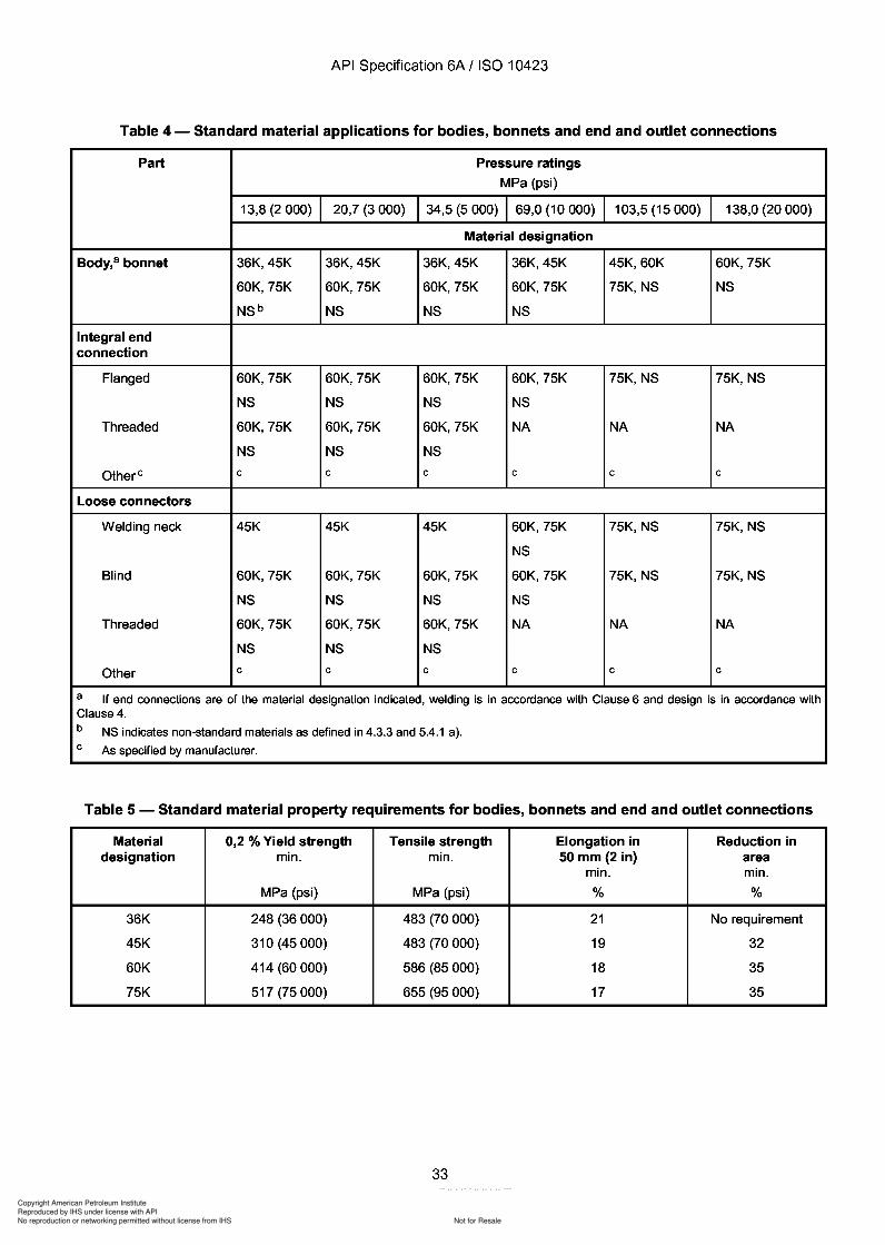
33
Copyright American Petroleum Institute
Reproduced by IHS under license with API
Not for ResaleNo reproduction or networking permitted without license from IHS
--`,,`,`,-`-`,,`,,`,`,,`---
API Specification 6A / ISO 10423
Table 4 - Standard material applications for bodies, bonnets and end and outlet connections
Part Pressure ratings
MPa (psi)
13,8 (2 000) 20,7 (3000) 34,5 (5 000) 69,0 (10 000) 103,5 (15 000) 138,0 (20 000)
Material designation
Body,a bonnet 36K,45K 36K,45K 36K,45K 36K,45K 45K,60K 60K, 75K
60K, 75K 60K, 75K 60K, 75K 60K, 75K 75K,NS NS
NSb NS NS NS
Integral endconnection
Flanged 60K, 75K 60K, 75K 60K, 75K 60K, 75K 75K,NS 75K,NS
NS NS NS NS
Threaded 60K, 75K 60K, 75K 60K, 75K NA NA NA
NS NS NS
Other e e e e e e e
Loose connectors
Welding neck 45K 45K 45K 60K, 75K 75K,NS 75K,NS
NS
Blind 60K, 75K 60K, 75K 60K, 75K 60K, 75K 75K,NS 75K,NS
NS NS NS NS
Threaded 60K, 75K 60K, 75K 60K, 75K NA NA NA
NS NS NS
Other e e e e e e
a If end connections are of the material designation indicated, welding is in accordance with Clause 6 and design is in accordance withClause 4.b NS indicates non-standard materials as defined in 4.3.3 and 5.4.1 a).e As specified by manufacturer.
Table 5 - Standard material property requirements for bodies, bonnets and end and outlet connections
Material 0,2 % Yield strength Tensile strength Elongation in Reduction indesignation min. min. 50 mm (2 in) area
min. min.
MPa (psi) MPa (psi) % %
36K 248 (36000) 483 (70000) 21 No requirement
45K 310 (45000) 483 (70000) 19 32
60K 414 (60000) 586 (85000) 18 35
75K 517 (75000) 655 (95000) 17 35
33
API Specification 6A / ISO 10423
Table 4 - Standard material applications for bodies, bonnets and end and outlet connections
Part Pressure ratings
MPa (psi)
13,8 (2 000) 20,7 (3000) 34,5 (5 000) 69,0 (10 000) 103,5 (15 000) 138,0 (20 000)
Material designation
Body, a bonnet 36K,45K 36K,45K 36K,45K 36K,45K 45K,60K 60K, 75K
60K, 75K 60K, 75K 60K, 75K 60K, 75K 75K,NS NS
NSb NS NS NS
Integral end connection
Flanged 60K, 75K 60K, 75K 60K, 75K 60K, 75K 75K,NS 75K,NS
NS NS NS NS
Threaded 60K, 75K 60K, 75K 60K, 75K NA NA NA
NS NS NS
Other e e e e e e e
Loose connectors
Welding neck 45K 45K 45K 60K, 75K 75K,NS 75K,NS
NS
Blind 60K, 75K 60K, 75K 60K, 75K 60K, 75K 75K,NS 75K,NS
NS NS NS NS
Threaded 60K, 75K 60K, 75K 60K, 75K NA NA NA
NS NS NS
Other e e e e e e
a If end connections are of the material designation indicated, welding is in accordance with Clause 6 and design is in accordance with Clause 4. b NS indicates non-standard materials as defined in 4.3.3 and 5.4.1 a). e As specified by manufacturer.
Table 5 - Standard material property requirements for bodies, bonnets and end and outlet connections
Material 0,2 % Yield strength Tensile strength Elongation in Reduction in designation min. min. 50 mm (2 in) area
min. min.
MPa (psi) MPa (psi) % %
36K 248 (36000) 483 (70000) 21 No requirement
45K 310 (45000) 483 (70000) 19 32
60K 414 (60000) 586 (85000) 18 35
75K 517 (75000) 655 (95000) 17 35
33
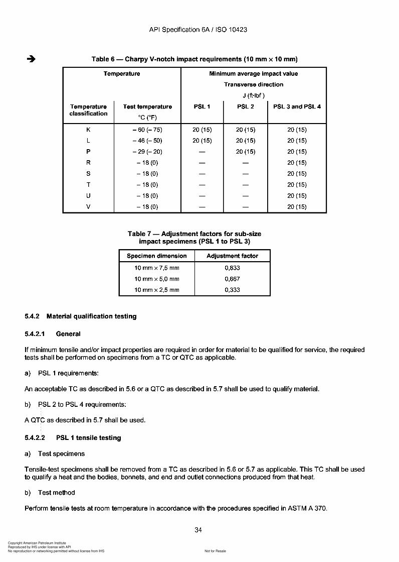
Copyright American Petroleum Institute
Reproduced by IHS under license with API
Not for ResaleNo reproduction or networking permitted without license from IHS
--`,,`,`,-`-`,,`,,`,`,,`---
Copyright American Petroleum Institute
Reproduced by IHS under license with API
Not for ResaleNo reproduction or networking permitted without license from IHS
--`,,`,`,-`-`,,`,,`,`,,`---
API Specification 6A / ISO 10423
Perform a minimum of one tensile test. The results of the tensile test(s) shall satisfy the applicable requirements ofTable 5.
c) Retesting
If the results of the tensile test(s) do not satisfy the applicable requirements, two additional tests on two additionaltest specimens (removed from the same TC or QTC with no additional heat treatment) may be performed in aneffort to qualify the material. The results of each of these tests shall satisfy the applicable requirements.
5.4.2.3 PSL 2 to PSL 4 tensile testing
a) Test specimens
Tensile test specimens shall be removed from a QTC as described in 5.7.
b) Test method
Perform tensile tests at room temperature in accordance with the procedures specified in ASTM A 370.
Perform a minimum of one tensile test. The results of the tensile test(s) shall satisfy the applicable requirements ofTable 5.
c) Retesting
If the results of the tensile test(s) do not satisfy the applicable requirements, two additional tests on two additionaltest specimens (removed from the same QTC with no additional heat treatment) may be performed in an effort toqualify the material. The results of each of these tests shall satisfy the applicable requirements.
5.4.2.4 PSL 1 to PSL 4 impact testing
a) Sampling
Impact tests shall be performed on a heat of material if a body, bonnet, or end and outlet connection produced fromthat heat requires testing.
b) Test specimens
Impact-test specimens shall be removed from a test coupon as described in 5.6 or 5.7 as applicable. This testcoupon shall be used to qualify a heat and the bodies, bonnets, and end and outlet connections produced from thatheat.
c) Test method
Perform impact tests in accordance with the procedures specified in ASTM A 370 using the Charpy V-notchtechnique.
In order to qualify material for a temperature rating, perform the impact tests at or below the lowest temperature ofthat classification range.
Test a minimum of three impact specimens to qualify a heat of material. Impact properties as determined fromthese tests shall satisfy the applicable requirements of Table 6. In no case shall an individual impact value fallbelow two-thirds of that required as a minimum average. Similarly, no more than one of the three test results shallbe below the required minimum average.
d) PSL 1 to PSL 4 retest
If a test fails, then a retest of three additional specimens removed from the same QTC (or TC for PSL 1components) with no additional heat treatment may be made, each of which shall exhibit an impact value equal toor exceeding the required minimum average value.
35
API Specification 6A / ISO 10423
Perform a minimum of one tensile test. The results of the tensile test(s) shall satisfy the applicable requirements of Table 5.
c) Retesting
If the results of the tensile test(s) do not satisfy the applicable requirements, two additional tests on two additional test specimens (removed from the same TC or QTC with no additional heat treatment) may be performed in an effort to qualify the material. The results of each of these tests shall satisfy the applicable requirements.
5.4.2.3 PSL 2 to PSL 4 tensile testing
a) Test specimens
Tensile test specimens shall be removed from a QTC as described in 5.7.
b) Test method
Perform tensile tests at room temperature in accordance with the procedures specified in ASTM A 370.
Perform a minimum of one tensile test. The results of the tensile test(s) shall satisfy the applicable requirements of Table 5.
c) Retesting
If the results of the tensile test(s) do not satisfy the applicable requirements, two additional tests on two additional test specimens (removed from the same QTC with no additional heat treatment) may be performed in an effort to qualify the material. The results of each of these tests shall satisfy the applicable requirements.
5.4.2.4 PSL 1 to PSL 4 impact testing
a) Sampling
Impact tests shall be performed on a heat of material if a body, bonnet, or end and outlet connection produced from that heat requires testing.
b) Test specimens
Impact-test specimens shall be removed from a test coupon as described in 5.6 or 5.7 as applicable. This test coupon shall be used to qualify a heat and the bodies, bonnets, and end and outlet connections produced from that heat.
c) Test method
Perform impact tests in accordance with the procedures specified in ASTM A 370 using the Charpy V-notch technique.
In order to qualify material for a temperature rating, perform the impact tests at or below the lowest temperature of that classification range.
Test a minimum of three impact specimens to qualify a heat of material. Impact properties as determined from these tests shall satisfy the applicable requirements of Table 6. In no case shall an individual impact value fall below two-thirds of that required as a minimum average. Similarly, no more than one of the three test results shall be below the required minimum average.
d) PSL 1 to PSL 4 retest
If a test fails, then a retest of three additional specimens removed from the same QTC (or TC for PSL 1 components) with no additional heat treatment may be made, each of which shall exhibit an impact value equal to or exceeding the required minimum average value.
35
Copyright American Petroleum Institute
Reproduced by IHS under license with API
Not for ResaleNo reproduction or networking permitted without license from IHS
--`,,`,`,-`-`,,`,,`,`,,`---
API Specification 6A / ISO 10423
e) Specimen orientation
The values listed in Table 6 are the minimum acceptable values for wrought products tested in the transversedirection and for castings and weld qualifications. Wrought products may be tested in the longitudinal directioninstead of the transverse direction and then shall exhibit 27 J (20 ft-Ibf) minimum average value.
5.4.3 Processing
5.4.3.1 Casting practices
a) PSL 1 requirements
All castings used for bodies, bonnets end and outlet connections shall meet applicable requirements of Clause 5and Clause 7.
-+ b) PSL 2 requirements
The requirements for PSL 2 are identical to the requirements for PSL 1. In addition the manufacturer shalldocument foundry practices which establish limits for sand control, core-making, rigging, melting and heattreatment and NDE to ensure repeatability in producing castings which meet the requirements of this InternationalStandard.
-+ c) PSL 3 and PSL 4 requirements
Wrought products shall be used.
5.4.3.2 Hot-working practices
a) PSL 1 requirements
All wrought material(s) shall be formed using a hot-working practice(s) which produces a wrought structurethroughout.
b) PSL 2 to PSL 4 requirements
The requirements for PSL 2 to PSL 4 are identical to the requirements for PSL 1. In addition the manufacturer shalldocument hot working practices.
5.4.3.3 Melting practices
a) PSL 1 to PSL 3 requirements
The manufacturer shall specify melting practices.
b) PSL 4 requirements
The requirements for PSL 4 are identical to the requirements for PSL 1 to PSL 3. In addition the manufacturer shalldocument the melting practice utilized for PSL 4 material.
5.4.4 Heat treating
5.4.4.1 Equipment qualification
All heat treatment operations shall be performed utilizing equipment qualified in accordance with the requirementsspecified by the manufacturer.
36
API Specification 6A / ISO 10423
e) Specimen orientation
The values listed in Table 6 are the minimum acceptable values for wrought products tested in the transverse direction and for castings and weld qualifications. Wrought products may be tested in the longitudinal direction instead of the transverse direction and then shall exhibit 27 J (20 ft-Ibf) minimum average value.
5.4.3 Processing
5.4.3.1 Casting practices
a) PSL 1 requirements
All castings used for bodies, bonnets end and outlet connections shall meet applicable requirements of Clause 5 and Clause 7.
-+ b) PSL 2 requirements
The requirements for PSL 2 are identical to the requirements for PSL 1. In addition the manufacturer shall document foundry practices which establish limits for sand control, core-making, rigging, melting and heat treatment and NDE to ensure repeatability in producing castings which meet the requirements of this International Standard.
-+ c) PSL 3 and PSL 4 requirements
Wrought products shall be used.
5.4.3.2 Hot-working practices
a) PSL 1 requirements
All wrought material(s) shall be formed using a hot-working practice(s) which produces a wrought structure throughout.
b) PSL 2 to PSL 4 requirements
The requirements for PSL 2 to PSL 4 are identical to the requirements for PSL 1. In addition the manufacturer shall document hot working practices.
5.4.3.3 Melting practices
a) PSL 1 to PSL 3 requirements
The manufacturer shall specify melting practices.
b) PSL 4 requirements
The requirements for PSL 4 are identical to the requirements for PSL 1 to PSL 3. In addition the manufacturer shall document the melting practice utilized for PSL 4 material.
5.4.4 Heat treating
5.4.4.1 Equipment qualification
All heat treatment operations shall be performed utilizing equipment qualified in accordance with the requirements specified by the manufacturer.
36
37
Copyright American Petroleum Institute
Reproduced by IHS under license with API
Not for ResaleNo reproduction or networking permitted without license from IHS
--`,,`,`,-`-`,,`,,`,`,,`---
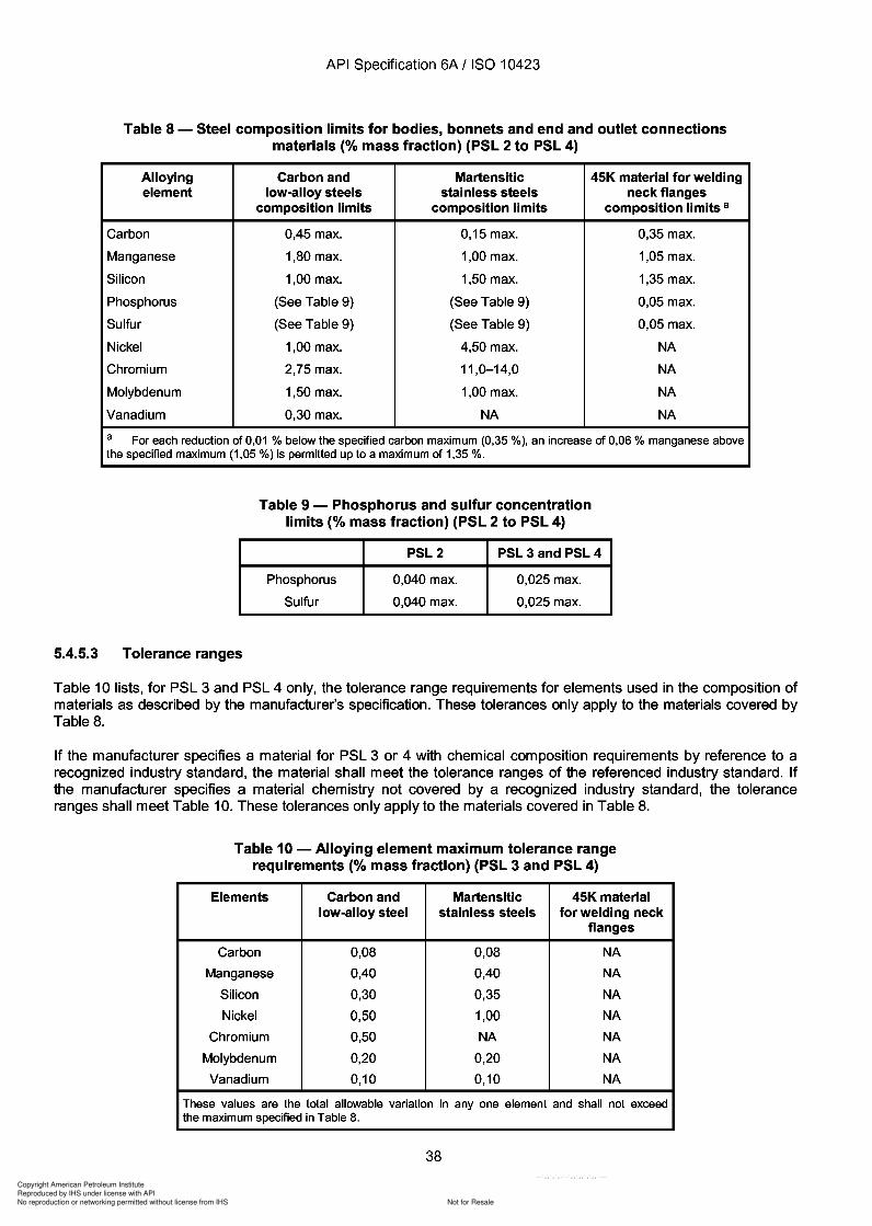
38
Copyright American Petroleum Institute
Reproduced by IHS under license with API
Not for ResaleNo reproduction or networking permitted without license from IHS
--`,,`,`,-`-`,,`,,`,`,,`---
API Specification 6A / ISO 10423
Table 8 - Steel composition limits for bodies, bonnets and end and outlet connectionsmaterials (% mass fraction) (PSL 2 to PSL 4)
Alloying Carbon and Martensitic 45K material for weldingelement low-alloy steels stainless steels neck flanges
composition limits composition limits composition limits a
Carbon 0,45 max. 0,15 max. 0,35 max.
Manganese 1,80 max. 1,00 max. 1,05 max.
Silicon 1,00 max. 1,50 max. 1,35 max.
Phosphorus (See Table 9) (See Table 9) 0,05 max.
Sulfur (See Table 9) (See Table 9) 0,05 max.
Nickel 1,00 max. 4,50 max. NA
Chromium 2,75 max. 11,0-14,0 NA
Molybdenum 1,50 max. 1,00 max. NA
Vanadium 0,30 max. NA NA
a For each reduction of 0,01 % below the specified carbon maximum (0,35 %), an increase of 0,06 % manganese abovethe specified maximum (1,05 %) is permitted upto a maximum of 1,35 %.
Table 9 - Phosphorus and sulfur concentrationlimits (% mass fraction) (PSL 2 to PSL 4)
PSL2 PSL 3 and PSL 4
Phosphorus 0,040 max. 0,025 max.
Sulfur 0,040 max. 0,025 max.
5.4.5.3 Tolerance ranges
Table 10 lists, for PSL 3 and PSL 4 only, the tolerance range requirements for elements used in the composition ofmaterials as described by the manufacturer's specification. These tolerances only apply to the materials covered byTable 8.
If the manufacturer specifies a material for PSL 3 or 4 with chemical composition requirements by reference to arecognized industry standard, the material shall meet the tolerance ranges of the referenced industry standard. Ifthe manufacturer specifies a material chemistry not covered by a recognized industry standard, the toleranceranges shall meet Table 10. These tolerances only apply to the materials covered in Table 8.
Table 10 - Alloying element maximum tolerance rangerequirements (% mass fraction) (PSL 3 and PSL 4)
Elements Carbon and Martensitic 45K materiallow-alloy steel stainless steels for welding neck
flanges
Carbon 0,08 0,08 NA
Manganese 0,40 0,40 NA
Silicon 0,30 0,35 NA
Nickel 0,50 1,00 NA
Chromium 0,50 NA NA
Molybdenum 0,20 0,20 NA
Vanadium 0,10 0,10 NA
These values are the total allowable variation in anyone element and shall not exceedthe maximum specified in Table 8.
38
API Specification 6A / ISO 10423
Table 8 - Steel composition limits for bodies, bonnets and end and outlet connections materials (% mass fraction) (PSL 2 to PSL 4)
Alloying Carbon and Martensitic 45K material for welding element low-alloy steels stainless steels neck flanges
composition limits composition limits composition limits a
Carbon 0,45 max. 0,15 max. 0,35 max.
Manganese 1,80 max. 1,00 max. 1,05 max.
Silicon 1,00 max. 1,50 max. 1,35 max.
Phosphorus (See Table 9) (See Table 9) 0,05 max.
Sulfur (See Table 9) (See Table 9) 0,05 max.
Nickel 1,00 max. 4,50 max. NA
Chromium 2,75 max. 11,0-14,0 NA
Molybdenum 1,50 max. 1,00 max. NA
Vanadium 0,30 max. NA NA
a For each reduction of 0,01 % below the specified carbon maximum (0,35 %), an increase of 0,06 % manganese above the specified maximum (1,05 %) is permitted upto a maximum of 1,35 %.
5.4.5.3 Tolerance ranges
Table 9 - Phosphorus and sulfur concentration limits (% mass fraction) (PSL 2 to PSL 4)
PSL2 PSL 3 and PSL 4
Phosphorus 0,040 max. 0,025 max.
Sulfur 0,040 max. 0,025 max.
Table 10 lists, for PSL 3 and PSL 4 only, the tolerance range requirements for elements used in the composition of materials as described by the manufacturer's specification. These tolerances only apply to the materials covered by Table 8.
If the manufacturer specifies a material for PSL 3 or 4 with chemical composition requirements by reference to a recognized industry standard, the material shall meet the tolerance ranges of the referenced industry standard. If the manufacturer specifies a material chemistry not covered by a recognized industry standard, the tolerance ranges shall meet Table 10. These tolerances only apply to the materials covered in Table 8.
Table 10 - Alloying element maximum tolerance range requirements (% mass fraction) (PSL 3 and PSL 4)
Elements Carbon and Martensitic 45K material low-alloy steel stainless steels for welding neck
flanges
Carbon 0,08 0,08 NA
Manganese 0,40 0,40 NA
Silicon 0,30 0,35 NA
Nickel 0,50 1,00 NA
Chromium 0,50 NA NA
Molybdenum 0,20 0,20 NA
Vanadium 0,10 0,10 NA
These values are the total allowable variation in anyone element and shall not exceed the maximum specified in Table 8.
38
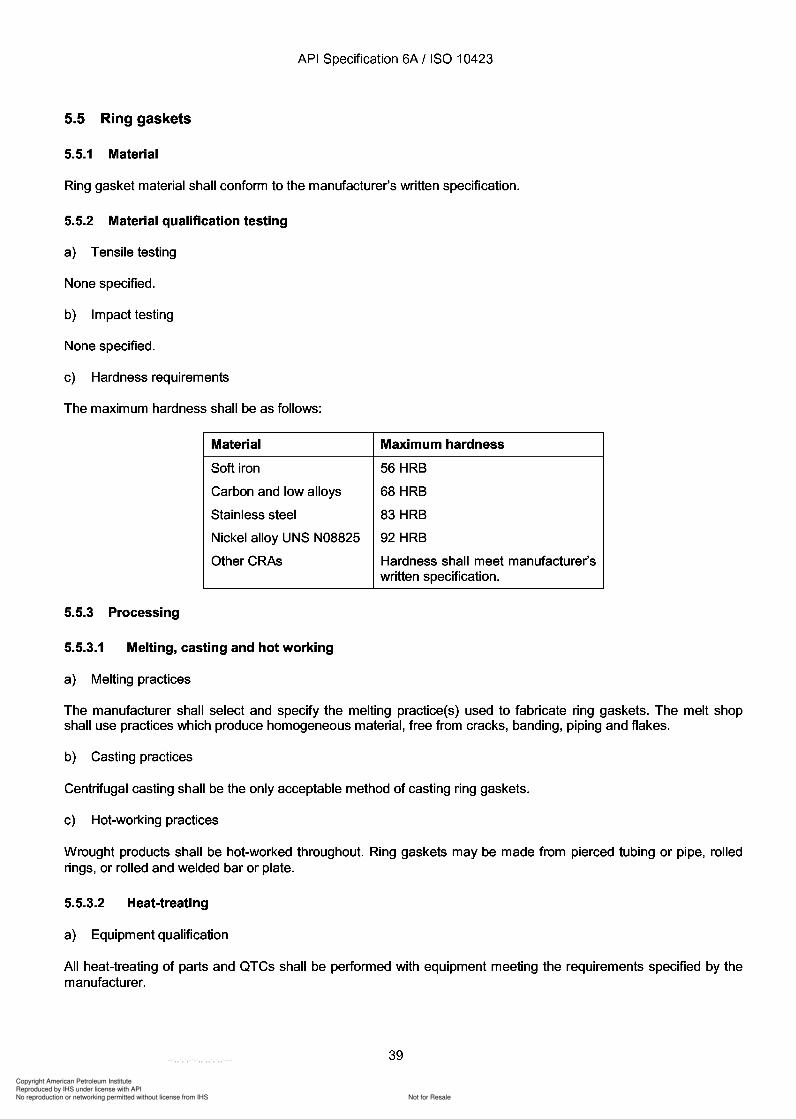
39
Copyright American Petroleum Institute
Reproduced by IHS under license with API
Not for ResaleNo reproduction or networking permitted without license from IHS
--`,,`,`,-`-`,,`,,`,`,,`---
API Specification 6A / ISO 10423
5.5 Ring gaskets
5.5.1 Material
Ring gasket material shall conform to the manufacturer's written specification.
5.5.2 Material qualification testing
a) Tensile testing
None specified.
b) Impacttesting
None specified.
c) Hardness requirements
The maximum hardness shall be as follows:
Material Maximum hardness
Soft iron 56 HRB
Carbon and low alloys 68 HRB
Stainless steel 83 HRB
Nickel alloy UNS N08825 92 HRB
OtherCRAs Hardness shall meet manufacturer'swritten specification.
5.5.3 Processing
5.5.3.1 Melting, casting and hot working
a) Melting practices
The manufacturer shall select and specify the melting practice(s) used to fabricate ring gaskets. The melt shopshall use practices which produce homogeneous material, free from cracks, banding, piping and flakes.
b) Casting practices
Centrifugal casting shall be the only acceptable method of casting ring gaskets.
c) Hot-working practices
Wrought products shall be hot-worked throughout. Ring gaskets may be made from pierced tubing or pipe, rolledrings, or rolled and welded bar or plate.
5.5.3.2 Heat-treating
a) Equipment qualification
All heat-treating of parts and QTCs shall be performed with equipment meeting the requirements specified by themanufacturer.
39
API Specification 6A / ISO 10423
5.5 Ring gaskets
5.5.1 Material
Ring gasket material shall conform to the manufacturer's written specification.
5.5.2 Material qualification testing
a) Tensile testing
None specified.
b) Impacttesting
None specified.
c) Hardness requirements
The maximum hardness shall be as follows:
Material Maximum hardness
Soft iron 56 HRB
Carbon and low alloys 68 HRB
Stainless steel 83 HRB
Nickel alloy UNS N08825 92 HRB
OtherCRAs Hardness shall meet manufacturer's written specification.
5.5.3 Processing
5.5.3.1 Melting, casting and hot working
a) Melting practices
The manufacturer shall select and specify the melting practice(s) used to fabricate ring gaskets. The melt shop shall use practices which produce homogeneous material, free from cracks, banding, piping and flakes.
b) Casting practices
Centrifugal casting shall be the only acceptable method of casting ring gaskets.
c) Hot-working practices
Wrought products shall be hot-worked throughout. Ring gaskets may be made from pierced tubing or pipe, rolled rings, or rolled and welded bar or plate.
5.5.3.2 Heat-treating
a) Equipment qualification
All heat-treating of parts and QTCs shall be performed with equipment meeting the requirements specified by the manufacturer.
39
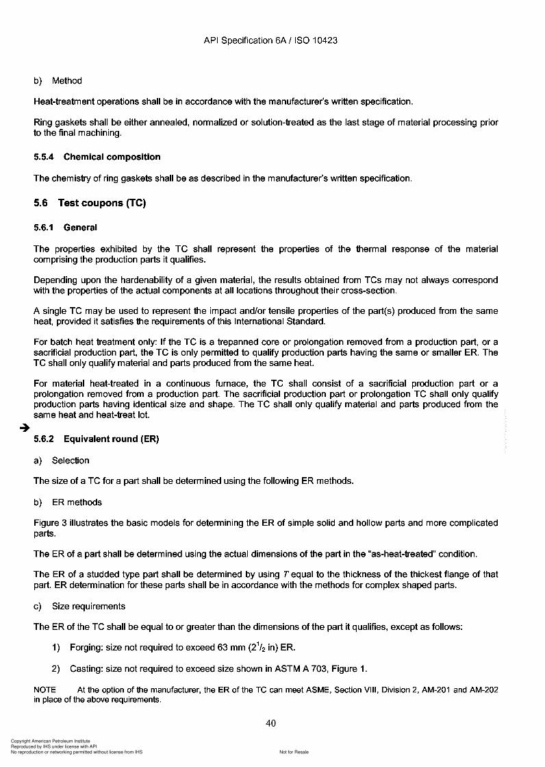
Copyright American Petroleum Institute
Reproduced by IHS under license with API
Not for ResaleNo reproduction or networking permitted without license from IHS
--`,,`,`,-`-`,,`,,`,`,,`---
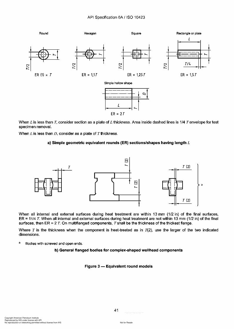
13 13
2
Copyright American Petroleum Institute
Reproduced by IHS under license with API
Not for ResaleNo reproduction or networking permitted without license from IHS
--`,,`,`,-`-`,,`,,`,`,,`---
API Specification 6A / ISO 10423
Round
ER (1) = T
Hexagon
ER=1,1T
Square
ER = 1,25 T
Rectangle or plate
L
--H·_·_· I-.--
T/4
ER = 1,5 T
Simple hollow shape
ER = 2T
When L is less than T, consider section as a plate of L thickness. Area inside dashed lines is 1/4 T envelope for testspecimen removal.
When L is less than D, consider as a plate of T thickness.
a) Simple geometric equivalent rounds (ER) sections/shapes having length L
TI-.
I-.
T (2)
T (2)
When all internal and external surfaces during heat treatment are within 13 mm (1/2 in) of the final surfaces,ER =11/4 T. When all internal and external surfaces during heat treatment are not within 13 mm (1/2 in) of the finalsurfaces, then ER =2 T. On multiflanged components, T shall be the thickness of the thickest flange.
Where T is the thickness when the component is heat-treated as in T(2), use the larger of the two indicateddimensions.
a Bodies with screwed and open ends.
b) General flanged bodies for complex-shaped wellhead components
Figure 3 - Equivalent round models
41
API Specification 6A / ISO 10423
Round Hexagon Square
ER (1) = T ER=1,1T ER = 1,25 T
Simple hollow shape
ER = 2 T
Rectangle or plate
L
--H·_·_· --
TI4
ER = 1,5 T
I---.
When L is less than T, consider section as a plate of L thickness. Area inside dashed lines is 1/4 T envelope for test specimen removal.
When L is less than D, consider as a plate of T thickness.
a) Simple geometric equivalent rounds (ER) sections/shapes having length L
T T (2)
T (2)
When all internal and external surfaces during heat treatment are within 13 mm (1/2 in) of the final surfaces, ER = 11/4 T. When all internal and external surfaces during heat treatment are not within 13 mm (1/2 in) of the final surfaces, then ER = 2 T. On multiflanged components, T shall be the thickness of the thickest flange.
Where T is the thickness when the component is heat-treated as in T(2), use the larger of the two indicated dimensions.
a Bodies with screwed and open ends.
b) General flanged bodies for complex-shaped wellhead components
Figure 3 - Equivalent round models
41
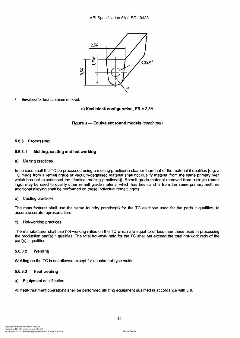
3
5.6.3
5.6.3.1
5.6.3.2
5.6.3.3
Copyright American Petroleum Institute
Reproduced by IHS under license with API
Not for ResaleNo reproduction or networking permitted without license from IHS
--`,,`,`,-`-`,,`,,`,`,,`---
Copyright American Petroleum Institute
Reproduced by IHS under license with API
Not for ResaleNo reproduction or networking permitted without license from IHS
--`,,`,`,-`-`,,`,,`,`,,`---
Copyright American Petroleum Institute
Reproduced by IHS under license with API
Not for ResaleNo reproduction or networking permitted without license from IHS
--`,,`,`,-`-`,,`,,`,`,,`---
API Specification 6A / ISO 10423
A single QTC may be used to represent the impact and/or tensile properties of the partes) produced from the sameheat, provided it satisfies the requirements of this International Standard.
For batch heat-treatment only: If the QTC is a trepanned core or prolongation removed from a production part, theQTC may only qualify production parts having the same or smaller ER. The QTC shall only qualify material andparts produced from the same heat.
For material heat treated in a continuous furnace, the QTC shall consist of a sacrificial production part or aprolongation removed from a production part. The sacrificial production part, or prolongation QTC shall only qualifyproduction parts having identical size and shape. The QTC shall only qualify material and parts produced from thesame heat and heat-treat lot.
-+5.7.2 Equivalent round (ER)
5.7.2.1 Selection
The size of a QTC for a part shall be determined using the ER methods given in 5.7.2.2.
5.7.2.2 ER methods
Figure 3 illustrates the basic models for determining the ER of simple solid and hollow parts and more complicatedparts.
The ER of a part shall be determined using the actual dimensions of the part in the "as-heat-treated" condition.
The ER of a studded type part shall be determined by using T equal to the thickness of the thickest flange of thatpart. ER determination for these parts shall be in accordance with the methods for complex-shaped parts.
5.7.2.3 Size requirements
The ER of the QTC shall be equal to or greater than the dimensions of the part it qualifies, except as follows:
a) For PSL 2
1) Forging: size not required to exceed 63 mm (21/ 2 in) ER.
2) Casting: size not required to exceed size shown in ASTM A 703.
b) For PSL 3 and PSL 4
Size not required to exceed 125 mm (5 in) ER.
NOTE At the option of the manufacturer, the ER of the QTe can meet ASME Section VIII, Division 2, AM-201 and AM-202in place of the above requirements.
5.7.3 Processing
5.7.3.1 Melting, casting and hot working
a) Melting practices
In no case shall the QTC be processed using a melting practice(s) cleaner than that of the material it qualifies [e.g.a QTC made from a remelt grade or vacuum-degassed material may not qualify material from the same primarymelt which has not experienced the identical melting practice(s)]. Remelt-grade material removed from a singleremelt ingot may be used to qualify other remelt-grade material which has been and is from the same primary melt;no additional alloying shall be performed on these individual remelt ingots. However, remelt-grade (consumableelectrode process) material used to fabricate parts having a PSL 4 shall be qualified on a remelt-ingot basis.
44
-+
API Specification 6A / ISO 10423
A single QTC may be used to represent the impact and/or tensile properties of the part(s) produced from the same heat, provided it satisfies the requirements of this International Standard.
For batch heat-treatment only: If the QTC is a trepanned core or prolongation removed from a production part, the QTC may only qualify production parts having the same or smaller ER. The QTC shall only qualify material and parts produced from the same heat.
For material heat treated in a continuous furnace, the QTC shall consist of a sacrificial production part or a prolongation removed from a production part. The sacrificial production part, or prolongation QTC shall only qualify production parts having identical size and shape. The QTC shall only qualify material and parts produced from the same heat and heat-treat lot.
5.7.2 Equivalent round (ER)
5.7.2.1 Selection
The size of a QTC for a part shall be determined using the ER methods given in 5.7.2.2.
5.7.2.2 ER methods
Figure 3 illustrates the basic models for determining the ER of simple solid and hollow parts and more complicated parts.
The ER of a part shall be determined using the actual dimensions of the part in the "as-heat-treated" condition.
The ER of a studded type part shall be determined by using T equal to the thickness of the thickest flange of that part. ER determination for these parts shall be in accordance with the methods for complex-shaped parts.
5.7.2.3 Size requirements
The ER of the QTC shall be equal to or greater than the dimensions of the part it qualifies, except as follows:
a) For PSL 2
1) Forging: size not required to exceed 63 mm (21/ 2 in) ER.
2) Casting: size not required to exceed size shown in ASTM A 703.
b) For PSL 3 and PSL 4
Size not required to exceed 125 mm (5 in) ER.
NOTE At the option of the manufacturer, the ER of the QTe can meet ASME Section VIII, Division 2, AM-201 and AM-202 in place of the above requirements.
5.7.3 Processing
5.7.3.1 Melting, casting and hot working
a) Melting practices
In no case shall the QTC be processed using a melting practice(s) cleaner than that of the material it qualifies [e.g. a QTC made from a remelt grade or vacuum-degassed material may not qualify material from the same primary melt which has not experienced the identical melting practice(s)]. Remelt-grade material removed from a single remelt ingot may be used to qualify other remelt-grade material which has been and is from the same primary melt; no additional alloying shall be performed on these individual remelt ingots. However, remelt-grade (consumable electrode process) material used to fabricate parts having a PSL 4 shall be qualified on a remelt-ingot basis.
44
Copyright American Petroleum Institute
Reproduced by IHS under license with API
Not for ResaleNo reproduction or networking permitted without license from IHS
--`,,`,`,-`-`,,`,,`,`,,`---
Copyright American Petroleum Institute
Reproduced by IHS under license with API
Not for ResaleNo reproduction or networking permitted without license from IHS
--`,,`,`,-`-`,,`,,`,`,,`---
API Specification 6A / ISO 10423
Standard-size 12,7 mm (0,500 in) diameter tensile specimens shall be used unless the physical configuration of theQTC prevents their use. In this case the standard sub-sized specimens referenced in ASTM A 370 may be used.
Standard-size impact specimens 10 mm x 10 mm in cross-section shall be used, except where there is insufficientmaterial, in which case the next smaller standard-size specimen obtainable shall be used. Impact specimens shallbe removed such that the notch is within the 1/4Tenvelope.
5.7.4.2 Hardness testing
At least one Rockwell or Brinell hardness test shall be performed on the QTC(s) after the final heat-treatment cycle.
The QTC heat-treatment cycles prior to hardness testing shall be the very same heat-treatment cycles experiencedby the tensile and impact test specimens. Hardness testing shall be performed in accordance with the proceduresin ASTM E 10 or ASTM E 18.
5.8 Heat-treating equipment qualification
All heat treating of parts, QTCs and TCs shall be performed with "production type" equipment meeting therequirements specified by the manufacturer.
"Production type" heat-treating equipment shall be considered equipment that is routinely used to processproduction parts having an ER equal to or greater than the ER of the subject TC.
5.9 Material qualification
If reference to this subclause is given in this International Standard, the manufacturer shall specify the methodsnecessary to qualify and test materials.
5.10 Bullplugs and valve-removal plugs
Material requirements for bullplugs and valve-removal plugs shall, as a minimum, be the same as those specifiedfor PSL 3 bodies, bonnets, end and outlet connections (see 5.4).
5.11 Back-pressure valves
Material requirements for back-pressure valves shall, as a minimum, be the same as those specified for PSL 3tubing hangers (see 5.3).
5.12 Pressure-boundary penetrations
Material requirements for pressure-boundary penetrations shall be as specified by the manufacturer. Pressureboundary penetrations directly exposed to well-bore fluid and used in sour service (material classes DO, EE, FF,and HH) shall meet the requirements of NACE MR 0175.
5.13 Wear bushings
Material requirements for wear bushings shall be as specified by the manufacturer. The hardness of the materialshall be between 241 HBW and 321 HBW.
5.14 Hub-end connectors
Material requirements for hubs, specified dimensionally in ISO 13533, shall be equal to the material requirementsof the equipment to which the hub is connected. Minimum requirements are those of PSL 2 bodies, bonnets, endand outlet connections (see 5.4).
46
API Specification 6A / ISO 10423
Standard-size 12,7 mm (0,500 in) diameter tensile specimens shall be used unless the physical configuration of the QTC prevents their use. In this case the standard sub-sized specimens referenced in ASTM A 370 may be used.
Standard-size impact specimens 10 mm x 10 mm in cross-section shall be used, except where there is insufficient material, in which case the next smaller standard-size specimen obtainable shall be used. Impact specimens shall be removed such that the notch is within the 1/4Tenvelope.
5.7.4.2 Hardness testing
At least one Rockwell or Brinell hardness test shall be performed on the QTC(s) after the final heat-treatment cycle.
The QTC heat-treatment cycles prior to hardness testing shall be the very same heat-treatment cycles experienced by the tensile and impact test specimens. Hardness testing shall be performed in accordance with the procedures in ASTM E 10 or ASTM E 18.
5.8 Heat-treating equipment qualification
All heat treating of parts, QTCs and TCs shall be performed with "production type" equipment meeting the requirements specified by the manufacturer.
"Production type" heat-treating equipment shall be considered equipment that is routinely used to process production parts having an ER equal to or greater than the ER of the subject TC.
5.9 Material qualification
If reference to this subclause is given in this International Standard, the manufacturer shall specify the methods necessary to qualify and test materials.
5.10 Bullplugs and valve-removal plugs
Material requirements for bull plugs and valve-removal plugs shall, as a minimum, be the same as those specified for PSL 3 bodies, bonnets, end and outlet connections (see 5.4).
5.11 Back-pressure valves
Material requirements for back-pressure valves shall, as a minimum, be the same as those specified for PSL 3 tubing hangers (see 5.3).
5.12 Pressure-boundary penetrations
Material requirements for pressure-boundary penetrations shall be as specified by the manufacturer. Pressureboundary penetrations directly exposed to well-bore fluid and used in sour service (material classes DO, EE, FF, and HH) shall meet the requirements of NACE MR 0175.
5.13 Wear bushings
Material requirements for wear bushings shall be as specified by the manufacturer. The hardness of the material shall be between 241 HBW and 321 HBW.
5.14 Hub-end connectors
Material requirements for hubs, specified dimensionally in ISO 13533, shall be equal to the material requirements of the equipment to which the hub is connected. Minimum requirements are those of PSL 2 bodies, bonnets, end and outlet connections (see 5.4).
46
Copyright American Petroleum Institute
Reproduced by IHS under license with API
Not for ResaleNo reproduction or networking permitted without license from IHS
--`,,`,`,-`-`,,`,,`,`,,`---
API Specification 6A / ISO 10423
6 Welding - General requirements
6.1 General
Requirements are established in four groups as follows:
a) Non-pressure-containing weldments other than weld overlays: PSL 1 to PSL 3.
b) Pressure-containing fabrication weldments for bodies, bonnets, and end and outlet connections, bullplugs,valve-removal plugs and back-pressure valves: PSL 1 to PSL 3.
c) Pressure-containing repair weldments for bodies, bonnets, and end and outlet connections, bullplugs, valveremoval plugs and back-pressue valves: PSL 1 to PSL 3.
d) Weld overlay for corrosion resistance and/or hard facing and other material surface property controls: PSL 1 toPSL4.
6.2 Non-pressure-containing weldments other than weld overlays (PSL 1 to PSL 3)
a) Welding procedure/performance
Welding procedures and performance qualifications shall be in accordance with ASME, Section IX, Articles IIand III.
b) Application
Welding shall be performed in accordance with qualified procedures by qualified welding personnel. Weld jointtypes and sizes shall meet the manufacturer's design requirements.
c) Quality control requirements
Welding and completed welds shall meet the requirements of Table 12.
6.3 Pressure-containing fabrication weldments for bodies, bonnets, end and outlet connections,bullplugs, valve-removal plugs and back-pressure valves
6.3.1 General
No fabrication welding is allowed on bullplugs and valve-removal plugs.
6.3.2 PSL 1
6.3.2.1 Joint design
Design of groove and fillet welds with tolerances shall be documented in the manufacturer's specifications.Annex E recommends weld groove designs.
6.3.2.2 Materials
a) Welding consumables
Welding consumables shall conform to American Welding Society or manufacturer's specifications. Themanufacturer shall have a written procedure for storage and control of welding consumables. Materials of lowhydrogen type shall be stored and used as recommended by the manufacturer of the welding consumable to retaintheir original low-hydrogen properties.
47
API Specification 6A / ISO 10423
6 Welding - General requirements
6.1 General
Requirements are established in four groups as follows:
a) Non-pressure-containing weldments other than weld overlays: PSL 1 to PSL 3.
b) Pressure-containing fabrication weldments for bodies, bonnets, and end and outlet connections, bullplugs, valve-removal plugs and back-pressure valves: PSL 1 to PSL 3.
c) Pressure-containing repair weldments for bodies, bonnets, and end and outlet connections, bull plugs, valveremoval plugs and back-pressue valves: PSL 1 to PSL 3.
d) Weld overlay for corrosion resistance and/or hard facing and other material surface property controls: PSL 1 to PSL4.
6.2 Non-pressure-containing weldments other than weld overlays (PSL 1 to PSL 3)
a) Welding procedure/performance
Welding procedures and performance qualifications shall be in accordance with ASME, Section IX, Articles II and III.
b) Application
Welding shall be performed in accordance with qualified procedures by qualified welding personnel. Weld joint types and sizes shall meet the manufacturer's design requirements.
c) Quality control requirements
Welding and completed welds shall meet the requirements of Table 12.
6.3 Pressure-containing fabrication weldments for bodies, bonnets, end and outlet connections, bullplugs, valve-removal plugs and back-pressure valves
6.3.1 General
No fabrication welding is allowed on bullplugs and valve-removal plugs.
6.3.2 PSL 1
6.3.2.1 Joint design
Design of groove and fillet welds with tolerances shall be documented in the manufacturer's specifications. Annex E recommends weld groove designs.
6.3.2.2 Materials
a) Welding consumables
Welding consumables shall conform to American Welding Society or manufacturer's specifications. The manufacturer shall have a written procedure for storage and control of welding consumables. Materials of lowhydrogen type shall be stored and used as recommended by the manufacturer of the welding consumable to retain their original low-hydrogen properties.
47
Copyright American Petroleum Institute
Reproduced by IHS under license with API
Not for ResaleNo reproduction or networking permitted without license from IHS
--`,,`,`,-`-`,,`,,`,`,,`---
Copyright American Petroleum Institute
Reproduced by IHS under license with API
Not for ResaleNo reproduction or networking permitted without license from IHS
--`,,`,`,-`-`,,`,,`,`,,`---
API Specification 6A / ISO 10423
b) Records
Records of welder performance qualification (WPQ) tests shall be in accordance with ASME, Section IX.
6.3.2.5 Welding requirements
a) Qualifications
Welding shall be in compliance with the qualified WPS and shall be performed by qualified welders/weldingoperators.
b) Use ofWPS
Welders and welding operators shall have access to, and shall comply with, the welding parameters as defined intheWPS.
c) Designed welds
All welds that are considered part of the design of a production part shall be specified by the manufacturer todescribe the requirements for the intended weld.
d) Preheating
Preheating of assemblies or parts, if required by the WPS, shall be performed to manufacturer's writtenprocedures.
6.3.2.6 Post-weld heat treatment
Post-weld heat treatment shall be in accordance with the applicable qualified WPS.
Welds may be locally post-weld heat-treated. The manufacturer shall specify procedures for the use of local postweld heat treatment.
6.3.2.7 Welding controls
a) Procedures
The manufacturer's welding control system shall include procedures for monitoring, updating and controlling thequalification of welders/welding operators and the use of welding procedure specifications.
b) Instrument calibration
Instruments to verify temperature, voltage and amperage shall be serviced and calibrated in accordance with themanufacturer's written specifications.
6.3.3 PSL 2
6.3.3.1 General
The requirements for PSL 1 shall also apply for PSL 2, in addition to the requirements given in 6.3.3.2 to 6.3.3.4.
6.3.3.2 Welding procedure qualification
a) Base metal groupings
Each base material which is not listed in an ASME, Section IX P-number or S-number grouping shall be specificallyqualified by the manufacturer.
49
API Specification 6A / ISO 10423
b) Records
Records of welder performance qualification (WPQ) tests shall be in accordance with ASME, Section IX.
6.3.2.5 Welding requirements
a) Qualifications
Welding shall be in compliance with the qualified WPS and shall be performed by qualified welders/welding operators.
b) Use ofWPS
Welders and welding operators shall have access to, and shall comply with, the welding parameters as defined in theWPS.
c) Designed welds
All welds that are considered part of the design of a production part shall be specified by the manufacturer to describe the requirements for the intended weld.
d) Preheating
Preheating of assemblies or parts, if required by the WPS, shall be performed to manufacturer's written procedures.
6.3.2.6 Post-weld heat treatment
Post-weld heat treatment shall be in accordance with the applicable qualified WPS.
Welds may be locally post-weld heat-treated. The manufacturer shall specify procedures for the use of local postweld heat treatment.
6.3.2.7 Welding controls
a) Procedures
The manufacturer's welding control system shall include procedures for monitoring, updating and controlling the qualification of welders/welding operators and the use of welding procedure specifications.
b) Instrument calibration
Instruments to verify temperature, voltage and amperage shall be serviced and calibrated in accordance with the manufacturer's written specifications.
6.3.3 PSL 2
6.3.3.1 General
The requirements for PSL 1 shall also apply for PSL 2, in addition to the requirements given in 6.3.3.2 to 6.3.3.4.
6.3.3.2 Welding procedure qualification
a) Base metal groupings
Each base material which is not listed in an ASME, Section IX P-number or S-number grouping shall be specifically qualified by the manufacturer.
49
Copyright American Petroleum Institute
Reproduced by IHS under license with API
Not for ResaleNo reproduction or networking permitted without license from IHS
--`,,`,`,-`-`,,`,,`,`,,`---
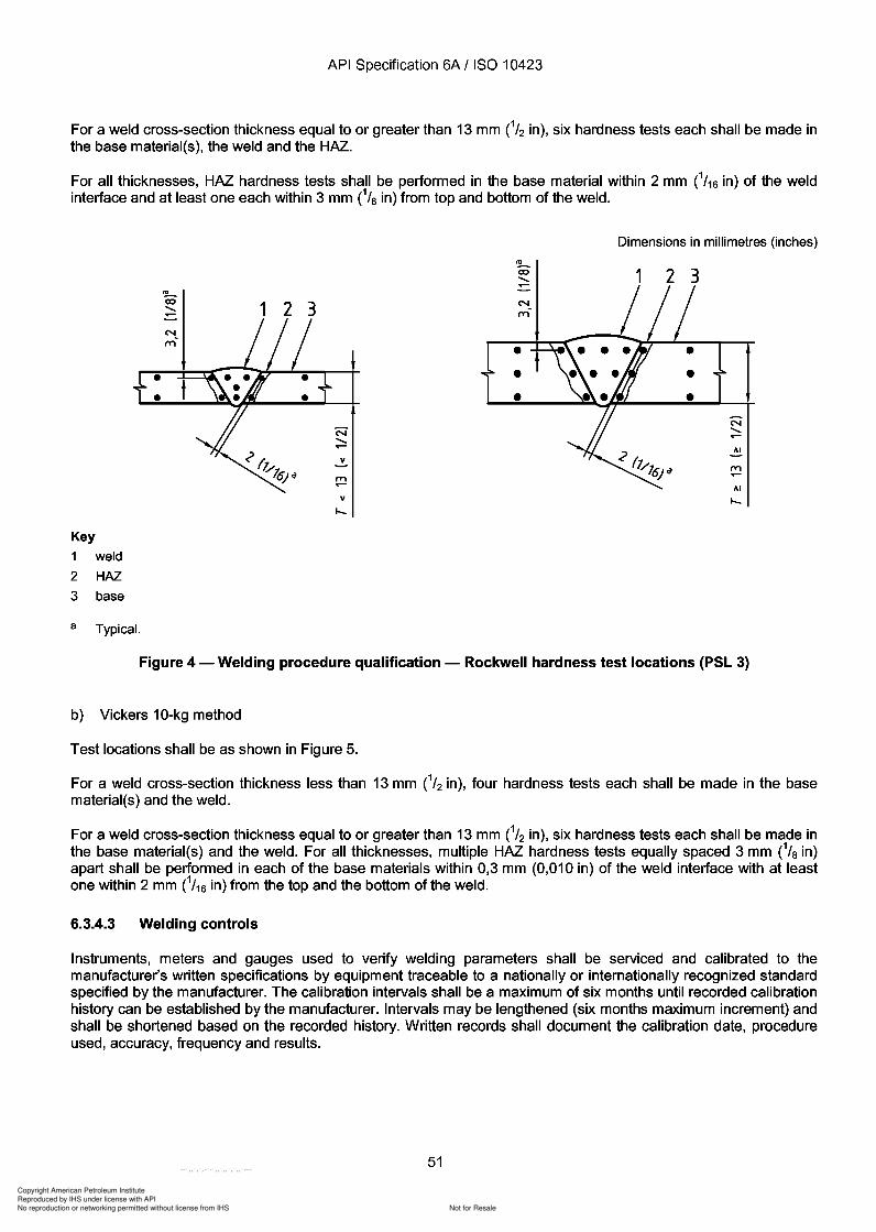
Copyright American Petroleum Institute
Reproduced by IHS under license with API
Not for ResaleNo reproduction or networking permitted without license from IHS
--`,,`,`,-`-`,,`,,`,`,,`---
API Specification 6A I ISO 10423
For a weld cross-section thickness equal to or greater than 13 mm CI2 in), six hardness tests each shall be made inthe base material(s), the weld and the HAZ.
For all thicknesses, HAZ hardness tests shall be performed in the base material within 2 mm C/16 in) of the weldinterface and at least one each within 3 mm CIa in) from top and bottom of the weld.
Key
1 weld
2 HAZ
3 base
'J!-.co............. 123
N.............v
,.."......v
~co.............N,..,,-
•••
Dimensions in millimetres (inches)
1 2 3
N.............III
,.."......III
.....
a Typical.
Figure 4 - Welding procedure qualification - Rockwell hardness test locations (PSL 3)
b) Vickers 10-kg method
Test locations shall be as shown in Figure 5.
For a weld cross-section thickness less than 13 mm CI2 in), four hardness tests each shall be made in the basematerial(s) and the weld.
For a weld cross-section thickness equal to or greater than 13 mm CI2 in), six hardness tests each shall be made inthe base material(s) and the weld. For all thicknesses, multiple HAZ hardness tests equally spaced 3 mm CIa in)apart shall be performed in each of the base materials within 0,3 mm (0,010 in) of the weld interface with at leastone within 2 mm C/16 in) from the top and the bottom of the weld.
6.3.4.3 Welding controls
Instruments, meters and gauges used to verify welding parameters shall be serviced and calibrated to themanufacturer's written specifications by equipment traceable to a nationally or internationally recognized standardspecified by the manufacturer. The calibration intervals shall be a maximum of six months until recorded calibrationhistory can be established by the manufacturer. Intervals may be lengthened (six months maximum increment) andshall be shortened based on the recorded history. Written records shall document the calibration date, procedureused, accuracy, frequency and results.
51
API Specification 6A I ISO 10423
For a weld cross-section thickness equal to or greater than 13 mm CI2 in), six hardness tests each shall be made in the base material(s), the weld and the HAZ.
For all thicknesses, HAZ hardness tests shall be performed in the base material within 2 mm C/16 in) of the weld interface and at least one each within 3 mm CIa in) from top and bottom of the weld.
Key
1
2
3
a
weld
HAZ base
Typical.
'l!-. ClO ....... ~ 123
N ....... ~
v
,." ~
v
N ,.,,-
• • •
Dimensions in millimetres (inches)
1 2 3
N .......
III
,." ~
III
.....
Figure 4 - Welding procedure qualification - Rockwell hardness test locations (PSL 3)
b) Vickers 10-kg method
Test locations shall be as shown in Figure 5.
For a weld cross-section thickness less than 13 mm CI2 in), four hardness tests each shall be made in the base material(s) and the weld.
For a weld cross-section thickness equal to or greater than 13 mm CI2 in), six hardness tests each shall be made in the base material(s) and the weld. For all thicknesses, multiple HAZ hardness tests equally spaced 3 mm CIa in) apart shall be performed in each of the base materials within 0,3 mm (0,010 in) of the weld interface with at least one within 2 mm C/16 in) from the top and the bottom of the weld.
6.3.4.3 Welding controls
Instruments, meters and gauges used to verify welding parameters shall be serviced and calibrated to the manufacturer's written specifications by equipment traceable to a nationally or internationally recognized standard specified by the manufacturer. The calibration intervals shall be a maximum of six months until recorded calibration history can be established by the manufacturer. Intervals may be lengthened (six months maximum increment) and shall be shortened based on the recorded history. Written records shall document the calibration date, procedure used, accuracy, frequency and results.
51
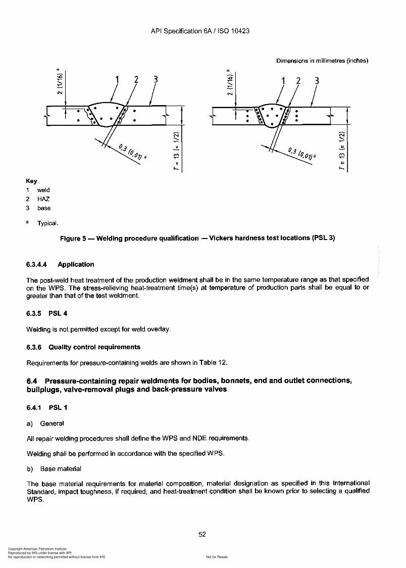
Copyright American Petroleum Institute
Reproduced by IHS under license with API
Not for ResaleNo reproduction or networking permitted without license from IHS
--`,,`,`,-`-`,,`,,`,`,,`---
Copyright American Petroleum Institute
Reproduced by IHS under license with API
Not for ResaleNo reproduction or networking permitted without license from IHS
--`,,`,`,-`-`,,`,,`,`,,`---
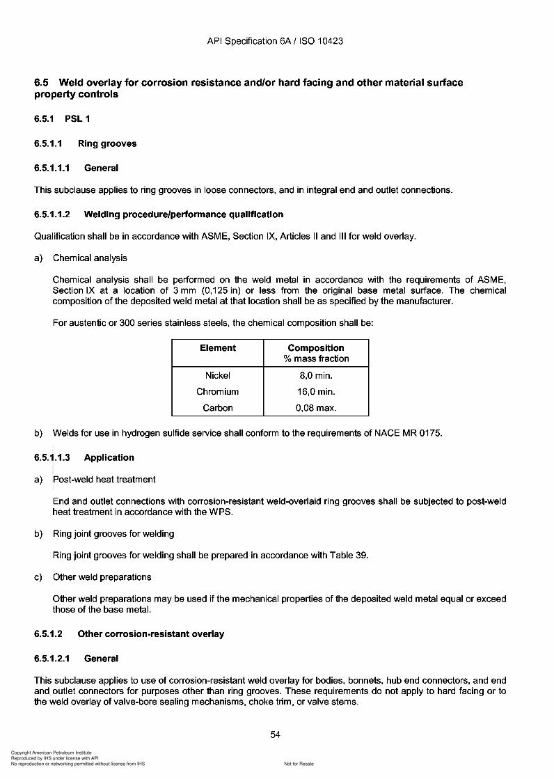
Copyright American Petroleum Institute
Reproduced by IHS under license with API
Not for ResaleNo reproduction or networking permitted without license from IHS
--`,,`,`,-`-`,,`,,`,`,,`---
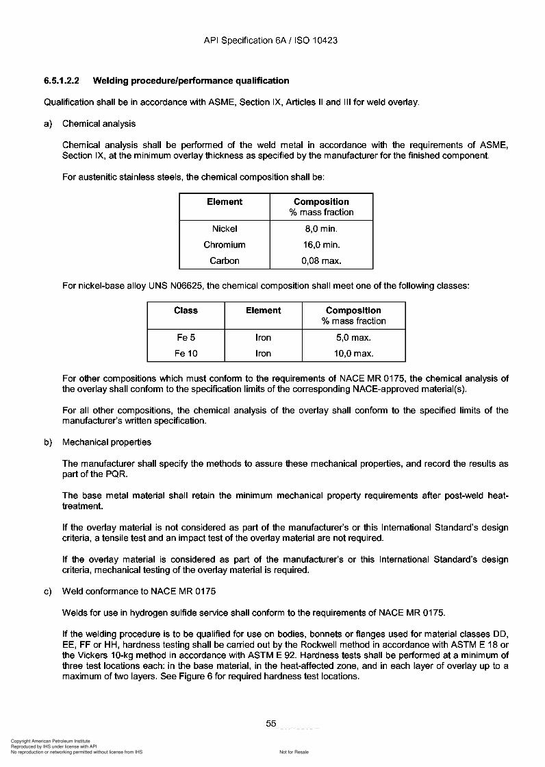
Copyright American Petroleum Institute
Reproduced by IHS under license with API
Not for ResaleNo reproduction or networking permitted without license from IHS
--`,,`,`,-`-`,,`,,`,`,,`---
API Specification 6A / ISO 10423
6.5.1.2.2 Welding procedure/performance qualification
Qualification shall be in accordance with ASME, Section IX, Articles II and III for weld overlay.
a) Chemical analysis
Chemical analysis shall be performed of the weld metal in accordance with the requirements of ASME,Section IX, at the minimum overlay thickness as specified by the manufacturer for the finished component.
For austenitic stainless steels, the chemical composition shall be:
Element Composition% mass fraction
Nickel 8,0 min.
Chromium 16,0 min.
Carbon 0,08 max.
For nickel-base alloy UNS N06625, the chemical composition shall meet one of the following classes:
Class Element Composition% mass fraction
Fe5 Iron 5,0 max.
Fe 10 Iron 10,0 max.
For other compositions which must conform to the requirements of NACE MR 0175, the chemical analysis ofthe overlay shall conform to the specification limits of the corresponding NACE-approved material(s).
For all other compositions, the chemical analysis of the overlay shall conform to the specified limits of themanufacturer's written specification.
b) Mechanical properties
The manufacturer shall specify the methods to assure these mechanical properties, and record the results aspart of the PQR.
The base metal material shall retain the minimum mechanical property requirements after post-weld heattreatment.
If the overlay material is not considered as part of the manufacturer's or this International Standard's designcriteria, a tensile test and an impact test of the overlay material are not required.
If the overlay material is considered as part of the manufacturer's or this International Standard's designcriteria, mechanical testing of the overlay material is required.
c) Weld conformance to NACE MR 0175
Welds for use in hydrogen sulfide service shall conform to the requirements of NACE MR 0175.
If the welding procedure is to be qualified for use on bodies, bonnets or flanges used for material classes DO,EE, FF or HH, hardness testing shall be carried out by the Rockwell method in accordance with ASTM E 18 orthe Vickers 10-kg method in accordance with ASTM E 92. Hardness tests shall be performed at a minimum ofthree test locations each: in the base material, in the heat-affected zone, and in each layer of overlay up to amaximum of two layers. See Figure 6 for required hardness test locations.
55
API Specification 6A / ISO 10423
6.5.1.2.2 Welding procedure/performance qualification
Qualification shall be in accordance with ASME, Section IX, Articles II and III for weld overlay.
a) Chemical analysis
Chemical analysis shall be performed of the weld metal in accordance with the requirements of ASME, Section IX, at the minimum overlay thickness as specified by the manufacturer for the finished component.
For austenitic stainless steels, the chemical composition shall be:
Element Composition % mass fraction
Nickel 8,0 min.
Chromium 16,0 min.
Carbon 0,08 max.
For nickel-base alloy UNS N06625, the chemical composition shall meet one of the following classes:
Class Element Composition % mass fraction
Fe5 Iron 5,0 max.
Fe 10 Iron 10,0 max.
For other compositions which must conform to the requirements of NACE MR 0175, the chemical analysis of the overlay shall conform to the specification limits of the corresponding NACE-approved material(s).
For all other compositions, the chemical analysis of the overlay shall conform to the specified limits of the manufacturer's written specification.
b) Mechanical properties
The manufacturer shall specify the methods to assure these mechanical properties, and record the results as part of the PQR.
The base metal material shall retain the minimum mechanical property requirements after post-weld heattreatment.
If the overlay material is not considered as part of the manufacturer's or this International Standard's design criteria, a tensile test and an impact test of the overlay material are not required.
If the overlay material is considered as part of the manufacturer's or this International Standard's design criteria, mechanical testing of the overlay material is required.
c) Weld conformance to NACE MR 0175
Welds for use in hydrogen sulfide service shall conform to the requirements of NACE MR 0175.
If the welding procedure is to be qualified for use on bodies, bonnets or flanges used for material classes DO, EE, FF or HH, hardness testing shall be carried out by the Rockwell method in accordance with ASTM E 18 or the Vickers 10-kg method in accordance with ASTM E 92. Hardness tests shall be performed at a minimum of three test locations each: in the base material, in the heat-affected zone, and in each layer of overlay up to a maximum of two layers. See Figure 6 for required hardness test locations.
55
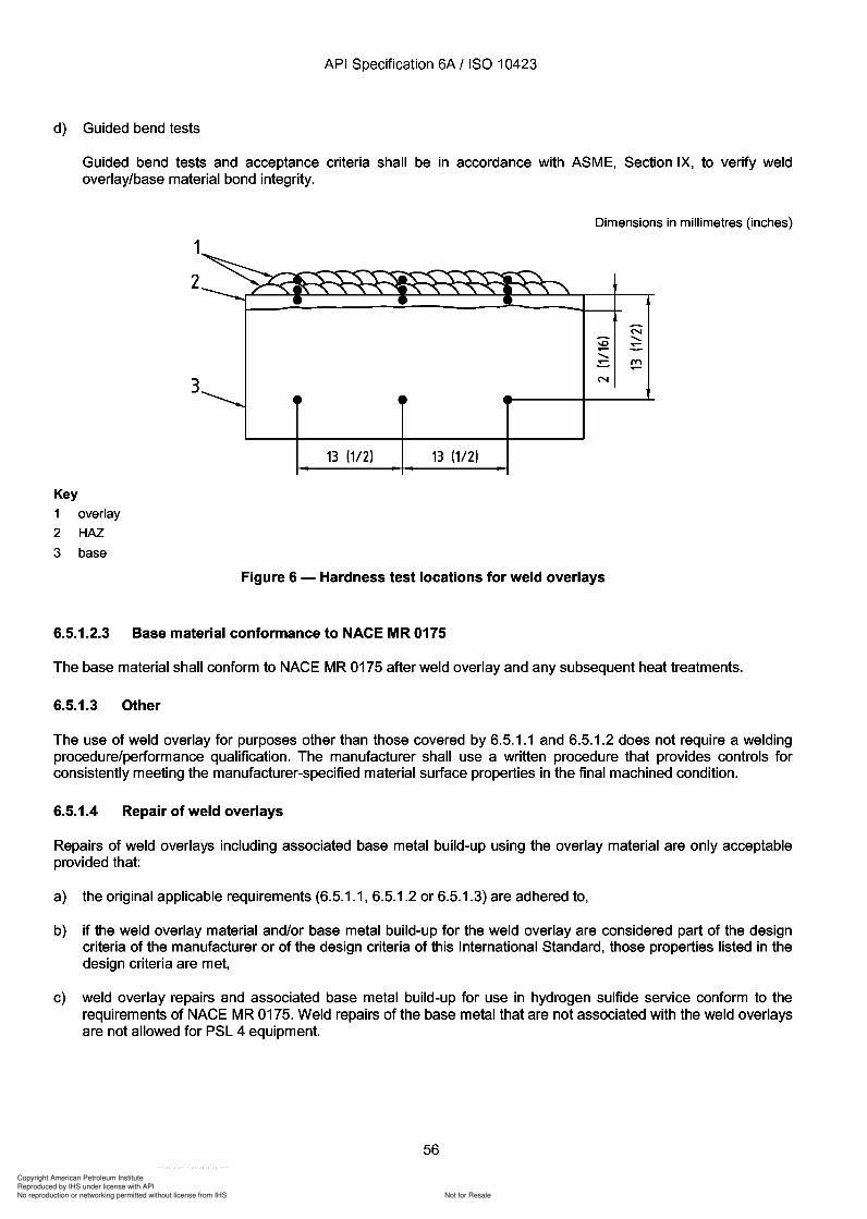
Copyright American Petroleum Institute
Reproduced by IHS under license with API
Not for ResaleNo reproduction or networking permitted without license from IHS
--`,,`,`,-`-`,,`,,`,`,,`---
API Specification 6A / ISO 10423
d) Guided bend tests
Guided bend tests and acceptance criteria shall be in accordance with ASME, Section IX, to verify weldoverlay/base material bond integrity.
Dimensions in millimetres (inches)
1
2
N
-0.......
~
~
.......~ m
~
3 N
Key
1 overlay
2 HAZ
3 base
13 (112) 13 (112)
Figure 6 - Hardness test locations for weld overlays
6.5.1.2.3 Base material conformance to NACE MR 0175
The base material shall conform to NACE MR 0175 after weld overlay and any subsequent heat treatments.
6.5.1.3 Other
The use of weld overlay for purposes other than those covered by 6.5.1.1 and 6.5.1.2 does not require a weldingprocedure/performance qualification. The manufacturer shall use a written procedure that provides controls forconsistently meeting the manufacturer-specified material surface properties in the final machined condition.
6.5.1.4 Repair of weld overlays
Repairs of weld overlays including associated base metal build-up using the overlay material are only acceptableprovided that:
a) the original applicable requirements (6.5.1.1, 6.5.1.2 or 6.5.1.3) are adhered to,
b) if the weld overlay material and/or base metal build-up for the weld overlay are considered part of the designcriteria of the manufacturer or of the design criteria of this International Standard, those properties listed in thedesign criteria are met,
c) weld overlay repairs and associated base metal build-up for use in hydrogen sulfide service conform to therequirements of NACE MR 0175. Weld repairs of the base metal that are not associated with the weld overlaysare not allowed for PSL 4 equipment.
56
API Specification 6A / ISO 10423
d) Guided bend tests
Guided bend tests and acceptance criteria shall be in accordance with ASME, Section IX, to verify weld overlay/base material bond integrity.
Dimensions in millimetres (inches)
1
2
('oj
-0 ....... ~
~
....... ~ m
3 ('oj
13 (112) 13 (112)
Key
1 overlay
2 HAZ
3 base
Figure 6 - Hardness test locations for weld overlays
6.5.1.2.3 Base material conformance to NACE M R 0175
The base material shall conform to NACE MR 0175 after weld overlay and any subsequent heat treatments.
6.5.1.3 Other
The use of weld overlay for purposes other than those covered by 6.5.1.1 and 6.5.1.2 does not require a welding procedure/performance qualification. The manufacturer shall use a written procedure that provides controls for consistently meeting the manufacturer-specified material surface properties in the final machined condition.
6.5.1.4 Repair of weld overlays
Repairs of weld overlays including associated base metal build-up using the overlay material are only acceptable provided that:
a) the original applicable requirements (6.5.1.1, 6.5.1.2 or 6.5.1.3) are adhered to,
b) if the weld overlay material and/or base metal build-up for the weld overlay are considered part of the design criteria of the manufacturer or of the design criteria of this International Standard, those properties listed in the design criteria are met,
c) weld overlay repairs and associated base metal build-up for use in hydrogen sulfide service conform to the requirements of NACE MR 0175. Weld repairs of the base metal that are not associated with the weld overlays are not allowed for PSL 4 equipment.
56
Copyright American Petroleum Institute
Reproduced by IHS under license with API
Not for ResaleNo reproduction or networking permitted without license from IHS
--`,,`,`,-`-`,,`,,`,`,,`---
Copyright American Petroleum Institute
Reproduced by IHS under license with API
Not for ResaleNo reproduction or networking permitted without license from IHS
--`,,`,`,-`-`,,`,,`,`,,`---
API Specification 6A / ISO 10423
7.2.2 Pressure-measuring devices
7.2.2.1 Type and accuracy
Test pressure-measuring devices shall be accurate to at least ± 0,5 % of full-scale range.
7.2.2.2 Calibration procedure
-+ Pressure-measuring devices shall be periodically recalibrated with a master pressure-measuring device or a deadweight tester at 25 %, 50 % and 75 % of full scale.
7.2.2.3 Calibration intervals
Calibration intervals shall be established for calibrations based on repeatability and degree of usage. Intervals maybe lengthened and shall be shortened based on recorded calibration history.
Calibration intervals shall be a maximum of 3 months until recorded calibration history can be established by themanufacturer and new longer intervals (3 months maximum increment) established.
7.3 Quality control personnel qualifications
7.3.1 Non-destructive examination (NOE) personnel
Personnel performing NDE shall be qualified in accordance with requirements specified in EN 473 or ASNT SNTTC-1A.
7.3.2 Visual examination personnel
Personnel performing visual examinations shall have an annual eye examination in accordance with EN 473 orASNT SNT-TC-1A.
7.3.3 Welding inspectors
Personnel performing visual inspections of welding operations and completed welds shall be qualified and certified as
AWS certified welding inspector, or
AWS senior certified welding inspector, or
AWS certified associate welding inspector, or
welding inspector certified by the manufacturer's documented training programme.
7.3.4 Other personnel
All personnel performing other quality control activities directly affecting material and product quality shall bequalified in accordance with manufacturer's documented requirements.
7.4 Quality control requirements
7.4.1 General
7.4.1.1 Quality control tables
Tables have been included in this subclause that provide a matrix of quality control requirements for specific partsand equipment.
58
API Specification 6A / ISO 10423
7.2.2 Pressure-measuring devices
7.2.2.1 Type and accuracy
Test pressure-measuring devices shall be accurate to at least ± 0,5 % of full-scale range.
7.2.2.2 Calibration procedure
-+ Pressure-measuring devices shall be periodically recalibrated with a master pressure-measuring device or a deadweight tester at 25 %, 50 % and 75 % of full scale.
7.2.2.3 Calibration intervals
Calibration intervals shall be established for calibrations based on repeatability and degree of usage. Intervals may be lengthened and shall be shortened based on recorded calibration history.
Calibration intervals shall be a maximum of 3 months until recorded calibration history can be established by the manufacturer and new longer intervals (3 months maximum increment) established.
7.3 Quality control personnel qualifications
7.3.1 Non-destructive examination (NOE) personnel
Personnel performing NDE shall be qualified in accordance with requirements specified in EN 473 or ASNT SNTTC-1A.
7.3.2 Visual examination personnel
Personnel performing visual examinations shall have an annual eye examination in accordance with EN 473 or ASNT SNT-TC-1A.
7.3.3 Welding inspectors
Personnel performing visual inspections of welding operations and completed welds shall be qualified and certified as
AWS certified welding inspector, or
AWS senior certified welding inspector, or
AWS certified associate welding inspector, or
welding inspector certified by the manufacturer's documented training programme.
7.3.4 Other personnel
All personnel performing other quality control activities directly affecting material and product quality shall be qualified in accordance with manufacturer's documented requirements.
7.4 Quality control requirements
7.4.1 General
7.4.1.1 Quality control tables
Tables have been included in this subclause that provide a matrix of quality control requirements for specific parts and equipment.
58
Copyright American Petroleum Institute
Reproduced by IHS under license with API
Not for ResaleNo reproduction or networking permitted without license from IHS
--`,,`,`,-`-`,,`,,`,`,,`---
API Specification 6A / ISO 10423
7.4.1.2 Materials
Clause 5 provides detailed qualification requirements for mandrel tubing and casing hangers; bodies, bonnet, endand outlet connections; ring gaskets; bullplugs and valve-removal plugs; back-pressure valves; pressure-boundarypenetrations; wear bushings; hub-end connectors and qualification test coupons.
7.4.1.3 Quality control instructions
All quality control work shall be controlled by the manufacturer's documented instructions which include appropriatemethodology and quantitative or qualitative acceptance criteria.
NDE instructions shall be detailed regarding the requirements of this International Standard and those of allapplicable nationally or internationally recognized standards specified by the manufacturer. All NDE instructionsshall be approved by a Level III Examiner.
7.4.1.4 Acceptance status
The acceptance status of all equipment, parts and materials shall be indicated either on the equipment, parts ormaterials or in records traceable to the equipment, parts or materials.
7.4.1.5 Material classes DO, EE, FF and HH
Each pressure-containing or pressure-controlling part to be used in H2S service shall be hardness-testedindividually to verify that the NACE MR 0175 hardness values have been satisfied (except for ring gaskets whichmay be sampled in accordance with 7.4.6.2). If the other requirements of 7.4.1 satisfy this requirement, additionaltesting or examination is not required.
7.4.2 Bodies, bonnets, end and outlet connections and hub end connectors (see Table 11)
7.4.2.1 PSL 1
7.4.2.1.1 Tensile testing
Tensile testing shall be in accordance with 5.4.2.2.
-+ 7.4.2.1.2 Impact testing (for temperature classifications K and L)
Impact testing shall be in accordance with 5.4.2.4.
7.4.2.1.3 Hardness testing
a) Sampling
Loose connectors do not require hardness testing.
For bodies, bonnets, end and outlet connections and hub end connectors with 13,8 MPa, 20,7 MPa and34,5 MPa (2000 psi, 3000 psi and 5000 psi) working pressure, sampling shall be in accordance withISO 2859-1, Level II, 4.0 AQL.
For bodies, bonnets, end and outlet connections and hub end connectors with 69,0 MPa, 103,5 MPa and138,0 MPa (10 000 psi, 15000 psi and 20 000 psi) working pressure, each part shall be hardness-tested.
b) Test method
Hardness testing shall be performed in accordance with procedures specified in ASTM E 10 or ASTM E 18.
Hardness conversion to other measurement units shall be in accordance with ASTM E 140.
59
API Specification 6A / ISO 10423
7.4.1.2 Materials
Clause 5 provides detailed qualification requirements for mandrel tubing and casing hangers; bodies, bonnet, end and outlet connections; ring gaskets; bull plugs and valve-removal plugs; back-pressure valves; pressure-boundary penetrations; wear bushings; hub-end connectors and qualification test coupons.
7.4.1.3 Quality control instructions
All quality control work shall be controlled by the manufacturer's documented instructions which include appropriate methodology and quantitative or qualitative acceptance criteria.
NDE instructions shall be detailed regarding the requirements of this International Standard and those of all applicable nationally or internationally recognized standards specified by the manufacturer. All NDE instructions shall be approved by a Level III Examiner.
7.4.1.4 Acceptance status
The acceptance status of all equipment, parts and materials shall be indicated either on the equipment, parts or materials or in records traceable to the equipment, parts or materials.
7.4.1.5 Material classes DO, EE, FF and HH
Each pressure-containing or pressure-controlling part to be used in H2S service shall be hardness-tested individually to verify that the NACE MR 0175 hardness values have been satisfied (except for ring gaskets which may be sampled in accordance with 7.4.6.2). If the other requirements of 7.4.1 satisfy this requirement, additional testing or examination is not required.
7.4.2 Bodies, bonnets, end and outlet connections and hub end connectors (see Table 11)
7.4.2.1 PSL 1
7.4.2.1.1 Tensile testing
Tensile testing shall be in accordance with 5.4.2.2.
-+ 7.4.2.1.2 Impact testing (for temperature classifications K and L)
Impact testing shall be in accordance with 5.4.2.4.
7.4.2.1.3 Hardness testing
a) Sampling
Loose connectors do not require hardness testing.
For bodies, bonnets, end and outlet connections and hub end connectors with 13,8 MPa, 20,7 MPa and 34,5 MPa (2000 psi, 3000 psi and 5000 psi) working pressure, sampling shall be in accordance with ISO 2859-1, Level II, 4.0 AQL.
For bodies, bonnets, end and outlet connections and hub end connectors with 69,0 MPa, 103,5 MPa and 138,0 MPa (10 000 psi, 15000 psi and 20 000 psi) working pressure, each part shall be hardness-tested.
b) Test method
Hardness testing shall be performed in accordance with procedures specified in ASTM E 10 or ASTM E 18.
Hardness conversion to other measurement units shall be in accordance with ASTM E 140.
59
Copyright American Petroleum Institute
Reproduced by IHS under license with API
Not for ResaleNo reproduction or networking permitted without license from IHS
--`,,`,`,-`-`,,`,,`,`,,`---
Copyright American Petroleum Institute
Reproduced by IHS under license with API
Not for ResaleNo reproduction or networking permitted without license from IHS
--`,,`,`,-`-`,,`,,`,`,,`---
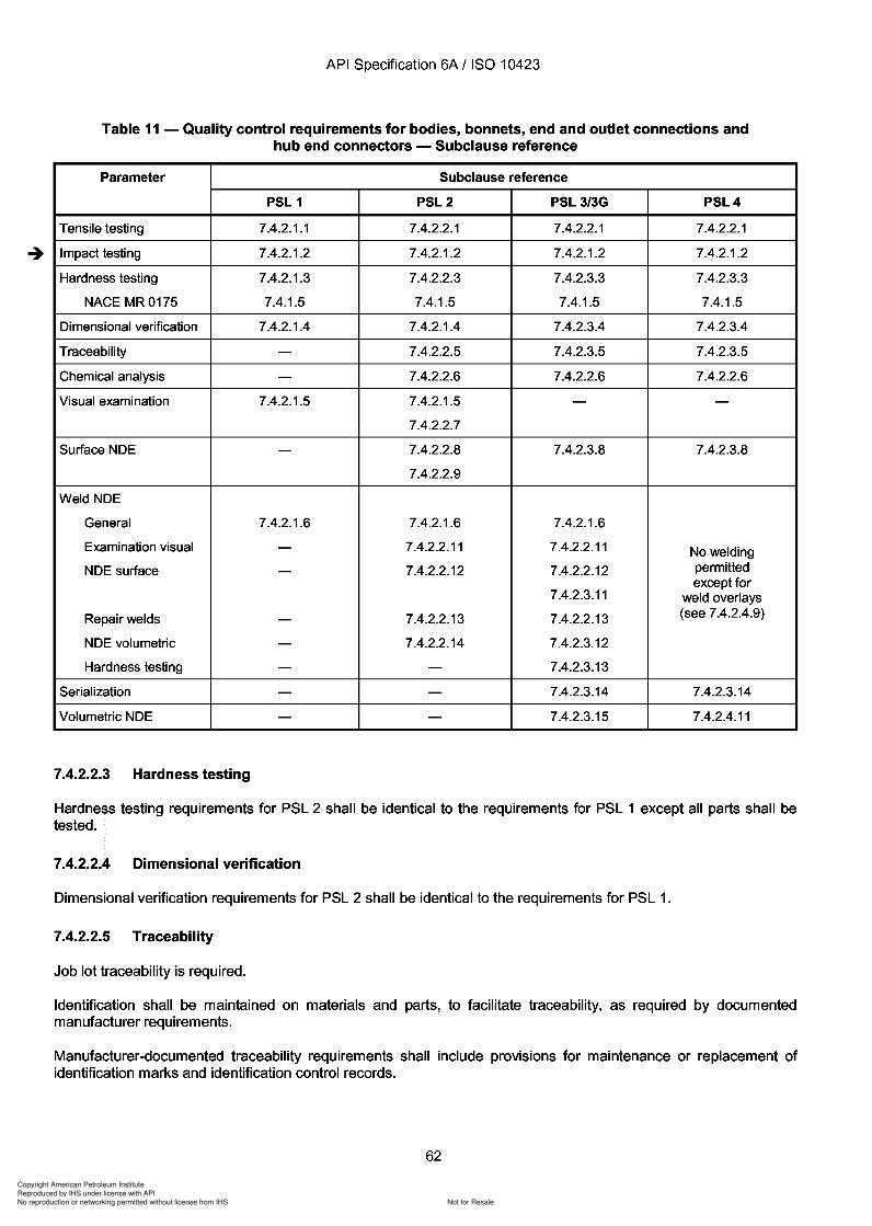
Copyright American Petroleum Institute
Reproduced by IHS under license with API
Not for ResaleNo reproduction or networking permitted without license from IHS
--`,,`,`,-`-`,,`,,`,`,,`---
Copyright American Petroleum Institute
Reproduced by IHS under license with API
Not for ResaleNo reproduction or networking permitted without license from IHS
--`,,`,`,-`-`,,`,,`,`,,`---
Copyright American Petroleum Institute
Reproduced by IHS under license with API
Not for ResaleNo reproduction or networking permitted without license from IHS
--`,,`,`,-`-`,,`,,`,`,,`---
API Specification 6A / ISO 10423
c) Acceptance criteria
The following acceptance criteria apply:
no relevant linear indications;
no relevant rounded indication with a major dimension equal to or greater than 5 mm C/16 in);
four or more relevant rounded indications in a line separated by less than 1,6 mm C/16 in) (edge to edge)are unacceptable;
no relevant indications in pressure-contact sealing surfaces.
7.4.2.2.10 Weld NDE - General
General requirements for PSL 2 shall be identical to the requirements for PSL 1.
7.4.2.2.11 Weld examination - Visual
a) Sampling
100 % of all welds shall be visually examined after post-weld heat treatment and machining operations.
b) Test method
Examinations shall include a minimum of 13 mm C/2 in) of adjacent base metal on both sides of the weld.
c) Acceptance criteria
The following acceptance criteria apply.
All pressure-containing welds shall have complete joint penetration.
Undercut shall not reduce the thickness in the area (considering both sides) to below the minimumthickness.
Surface porosity and exposed slag are not permitted on or within 3 mm C/a in) of sealing surfaces.
7.4.2.2.12 Weld NDE - Surface
a) Sampling
100 % of all pressure-containing fabrication welds and weld overlay shall be examined by either magnetic-particle(in the case of ferromagnetic materials) or liquid-penetrant (in the case of non-ferromagnetic materials) methodsafter all welding, post-weld heat treatment and machining operations.
b) Test method/acceptance - Magnetic-particle examination
Examinations shall include a minimum of 13 mm C/2 in) of adjacent base metal on both sides of the weld.
Magnetic-particle examination shall be performed as described in 7.4.2.2.8 with additional acceptance criteria asfollows:
no relevant linear indications;
no rounded indications greater than 3 mm C/a in) for welds whose depth is 16 mm (% in) or less; or 5 mmC/16 in) for welds whose depth is greater than 16 mm (5/a in).
64
API Specification 6A I ISO 10423
c) Acceptance criteria
The following acceptance criteria apply:
no relevant linear indications;
no relevant rounded indication with a major dimension equal to or greater than 5 mm C/16 in);
four or more relevant rounded indications in a line separated by less than 1,6 mm C/16 in) (edge to edge) are unacceptable;
no relevant indications in pressure-contact sealing surfaces.
7.4.2.2.10 Weld NDE - General
General requirements for PSL 2 shall be identical to the requirements for PSL 1.
7.4.2.2.11 Weld examination - Visual
a) Sampling
100 % of all welds shall be visually examined after post-weld heat treatment and machining operations.
b) Test method
Examinations shall include a minimum of 13 mm CI2 in) of adjacent base metal on both sides of the weld.
c) Acceptance criteria
The following acceptance criteria apply.
All pressure-containing welds shall have complete joint penetration.
Undercut shall not reduce the thickness in the area (considering both sides) to below the minimum thickness.
Surface porosity and exposed slag are not permitted on or within 3 mm CIa in) of sealing surfaces.
7.4.2.2.12 Weld NDE - Surface
a) Sampling
100 % of all pressure-containing fabrication welds and weld overlay shall be examined by either magnetic-particle (in the case of ferromagnetic materials) or liquid-penetrant (in the case of non-ferromagnetic materials) methods after all welding, post-weld heat treatment and machining operations.
b) Test method/acceptance - Magnetic-particle examination
Examinations shall include a minimum of 13 mm CI2 in) of adjacent base metal on both sides of the weld.
Magnetic-particle examination shall be performed as described in 7.4.2.2.8 with additional acceptance criteria as follows:
no relevant linear indications;
no rounded indications greater than 3 mm CIa in) for welds whose depth is 16 mm (% in) or less; or 5 mm C/16 in) for welds whose depth is greater than 16 mm (5/a in).
64
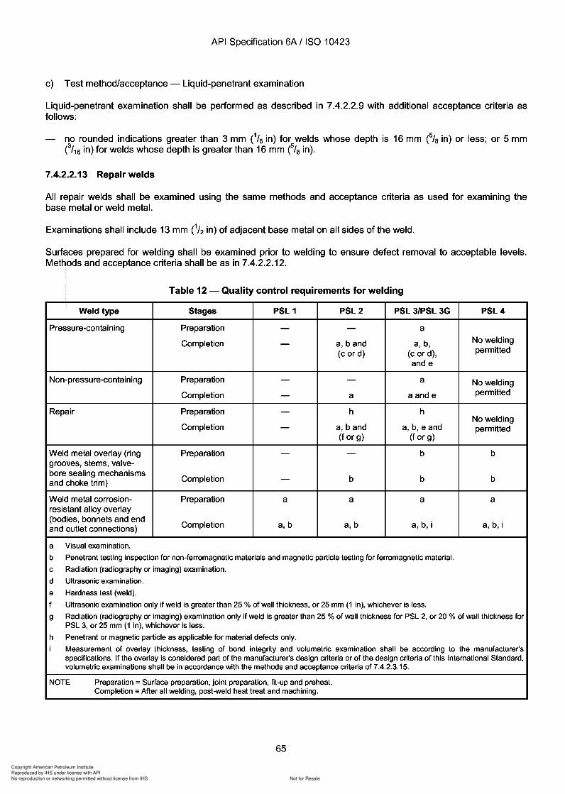
Copyright American Petroleum Institute
Reproduced by IHS under license with API
Not for ResaleNo reproduction or networking permitted without license from IHS
--`,,`,`,-`-`,,`,,`,`,,`---
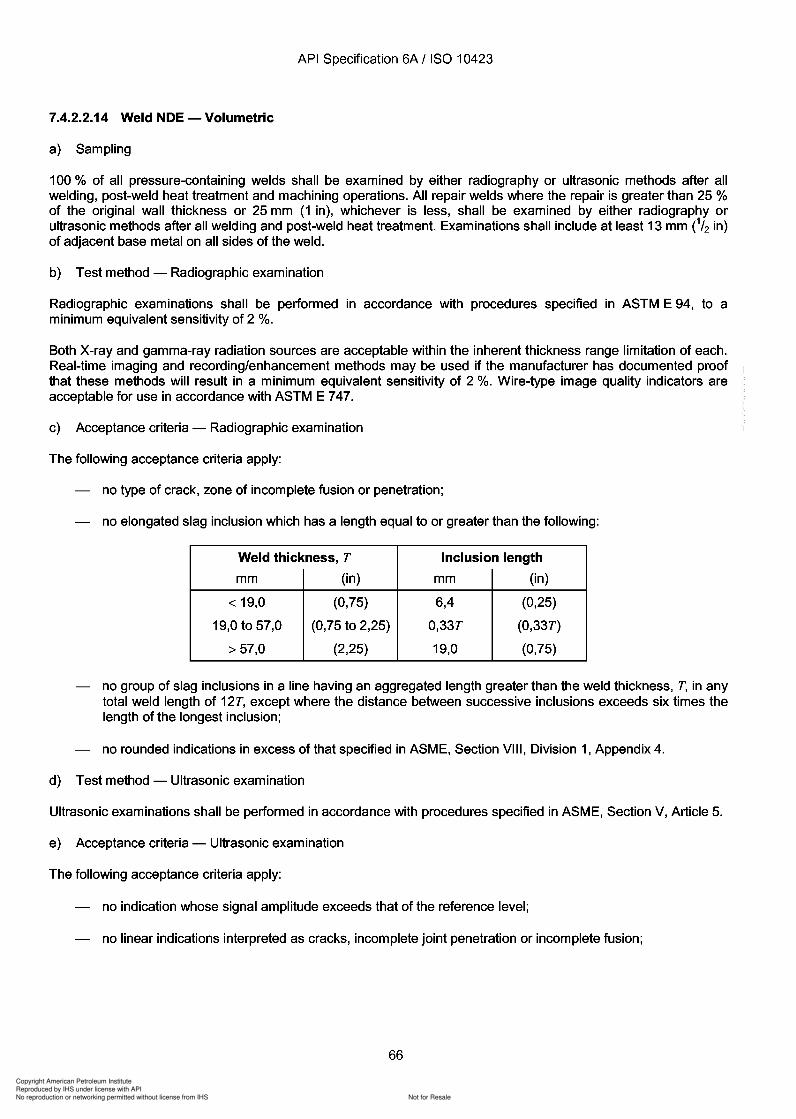
Copyright American Petroleum Institute
Reproduced by IHS under license with API
Not for ResaleNo reproduction or networking permitted without license from IHS
--`,,`,`,-`-`,,`,,`,`,,`---
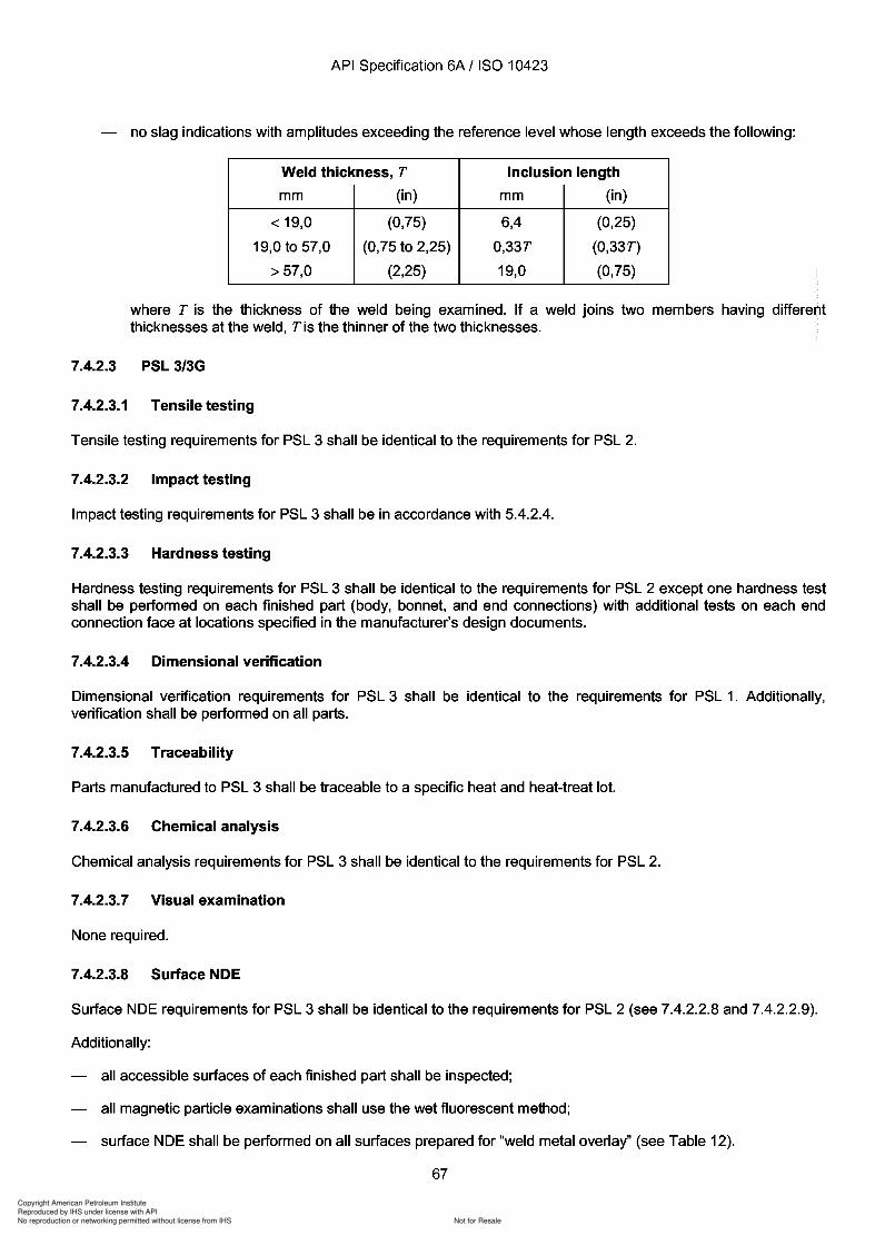
3
3
3
3
3
3
3
Copyright American Petroleum Institute
Reproduced by IHS under license with API
Not for ResaleNo reproduction or networking permitted without license from IHS
--`,,`,`,-`-`,,`,,`,`,,`---
Copyright American Petroleum Institute
Reproduced by IHS under license with API
Not for ResaleNo reproduction or networking permitted without license from IHS
--`,,`,`,-`-`,,`,,`,`,,`---
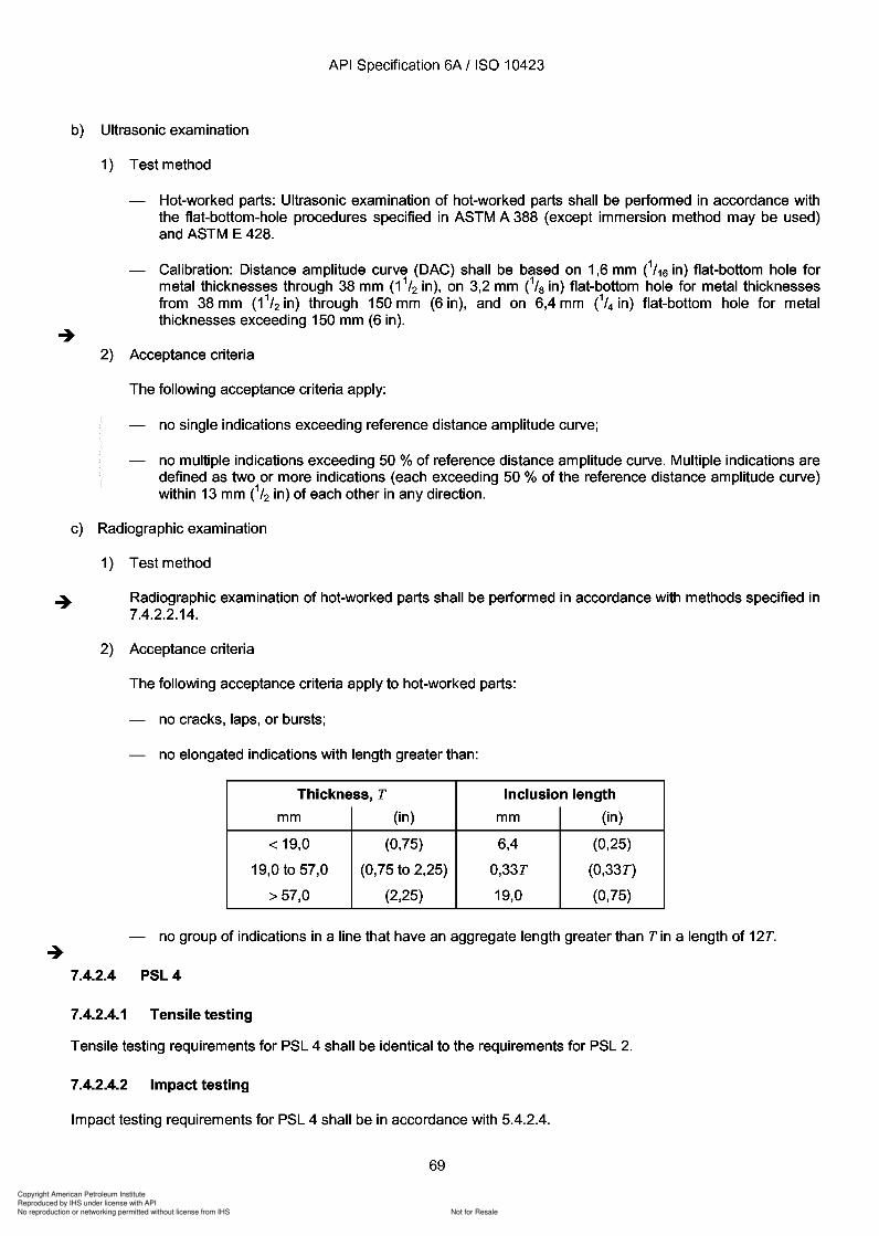
388 428.
1,6 38 3,2
38 150 6,4 150
13
7.4.2.2.14.
4 2.
4 5.4.2.4.
Copyright American Petroleum Institute
Reproduced by IHS under license with API
Not for ResaleNo reproduction or networking permitted without license from IHS
--`,,`,`,-`-`,,`,,`,`,,`---
Copyright American Petroleum Institute
Reproduced by IHS under license with API
Not for ResaleNo reproduction or networking permitted without license from IHS
--`,,`,`,-`-`,,`,,`,`,,`---
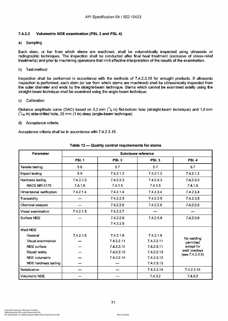
Copyright American Petroleum Institute
Reproduced by IHS under license with API
Not for ResaleNo reproduction or networking permitted without license from IHS
--`,,`,`,-`-`,,`,,`,`,,`---
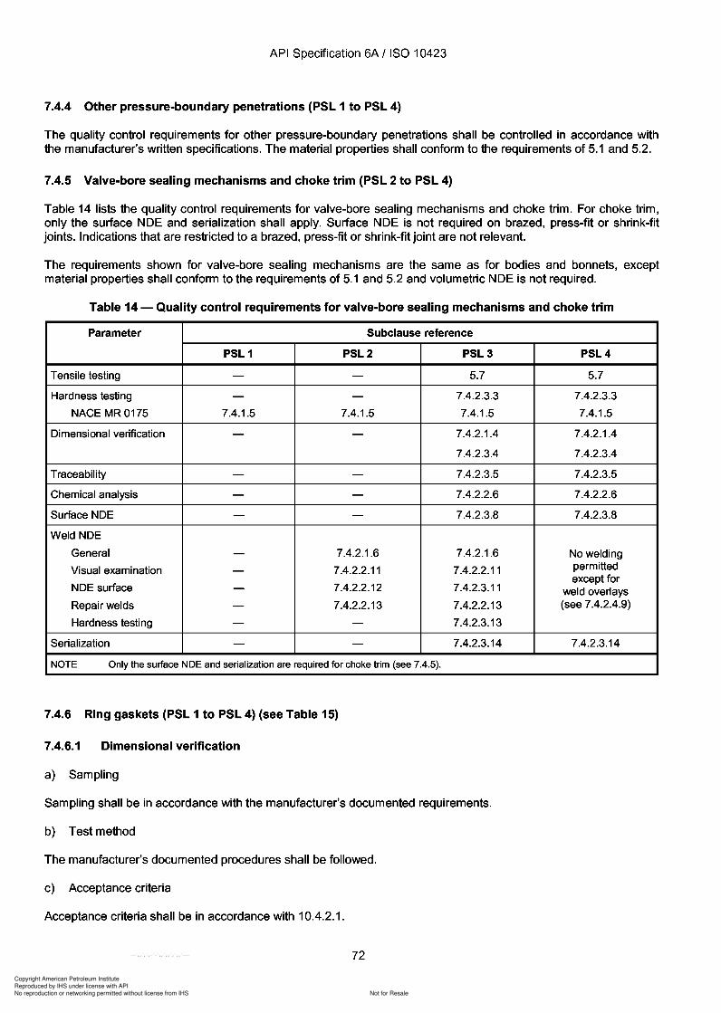
Copyright American Petroleum Institute
Reproduced by IHS under license with API
Not for ResaleNo reproduction or networking permitted without license from IHS
--`,,`,`,-`-`,,`,,`,`,,`---
API Specification 6A / ISO 10423
7.4.4 Other pressure-boundary penetrations (PSL 1 to PSL 4)
The quality control requirements for other pressure-boundary penetrations shall be controlled in accordance withthe manufacturer's written specifications. The material properties shall conform to the requirements of 5.1 and 5.2.
7.4.5 Valve-bore sealing mechanisms and choke trim (PSL 2 to PSL 4)
Table 14 lists the quality control requirements for valve-bore sealing mechanisms and choke trim. For choke trim,only the surface NDE and serialization shall apply. Surface NDE is not required on brazed, press-fit or shrink-fitjoints. Indications that are restricted to a brazed, press-fit or shrink-fit joint are not relevant.
The requirements shown for valve-bore sealing mechanisms are the same as for bodies and bonnets, exceptmaterial properties shall conform to the requirements of 5.1 and 5.2 and volumetric NDE is not required.
Table 14 - Quality control requirements for valve-bore sealing mechanisms and choke trim
Parameter Subclause reference
PSL 1 PSL2 PSL3 PSL4
Tensile testing - - 5.7 5.7
Hardness testing - - 7.4.2.3.3 7.4.2.3.3
NACE MR0175 7.4.1.5 7.4.1.5 7.4.1.5 7.4.1.5
Dimensional verification - - 7.4.2.1.4 7.4.2.1.4
7.4.2.3.4 7.4.2.3.4
Traceability - - 7.4.2.3.5 7.4.2.3.5
Chemical analysis - - 7.4.2.2.6 7.4.2.2.6
Surface NDE - - 7.4.2.3.8 7.4.2.3.8
Weld NDE
General - 7.4.2.1.6 7.4.2.1.6 No welding
Visual examination - 7.4.2.2.11 7.4.2.2.11 permitted
NDE surface 7.4.2.2.12 7.4.2.3.11except for
- weld overlaysRepair welds - 7.4.2.2.13 7.4.2.2.13 (see 7.4.2.4.9)
Hardness testing - - 7.4.2.3.13
Serialization - - 7.4.2.3.14 7.4.2.3.14
NOTE Only the surface NDE and serialization are required for choke trim (see 7.4.5).
7.4.6 Ring gaskets (PSL 1 to PSL 4) (see Table 15)
7.4.6.1 Dimensional verification
a) Sampling
Sampling shall be in accordance with the manufacturer's documented requirements.
b) Test method
The manufacturer's documented procedures shall be followed.
c) Acceptance criteria
Acceptance criteria shall be in accordance with 10.4.2.1.
72
API Specification 6A / ISO 10423
7.4.4 Other pressure-boundary penetrations (PSL 1 to PSL 4)
The quality control requirements for other pressure-boundary penetrations shall be controlled in accordance with the manufacturer's written specifications. The material properties shall conform to the requirements of 5.1 and 5.2.
7.4.5 Valve-bore sealing mechanisms and choke trim (PSL 2 to PSL 4)
Table 14 lists the quality control requirements for valve-bore sealing mechanisms and choke trim. For choke trim, only the surface NDE and serialization shall apply. Surface NDE is not required on brazed, press-fit or shrink-fit jOints. Indications that are restricted to a brazed, press-fit or shrink-fit joint are not relevant.
The requirements shown for valve-bore sealing mechanisms are the same as for bodies and bonnets, except material properties shall conform to the requirements of 5.1 and 5.2 and volumetric NDE is not required.
Table 14 - Quality control requirements for valve-bore sealing mechanisms and choke trim
Parameter Subclause reference
PSL 1 PSL2 PSL3 PSL4
Tensile testing - - 5.7 5.7
Hardness testing - - 7.4.2.3.3 7.4.2.3.3
NACE MR0175 7.4.1.5 7.4.1.5 7.4.1.5 7.4.1.5
Dimensional verification - - 7.4.2.1.4 7.4.2.1.4
7.4.2.3.4 7.4.2.3.4
Traceability - - 7.4.2.3.5 7.4.2.3.5
Chemical analysis - - 7.4.2.2.6 7.4.2.2.6
Surface NDE - - 7.4.2.3.8 7.4.2.3.8
Weld NDE
General - 7.4.2.1.6 7.4.2.1.6 No welding
Visual examination - 7.4.2.2.11 7.4.2.2.11 permitted
NDE surface 7.4.2.2.12 7.4.2.3.11 except for
- weld overlays Repair welds - 7.4.2.2.13 7.4.2.2.13 (see 7.4.2.4.9)
Hardness testing - - 7.4.2.3.13
Serialization - - 7.4.2.3.14 7.4.2.3.14
NOTE Only the surface NDE and serialization are required for choke trim (see 7.4.5).
7.4.6 Ring gaskets (PSL 1 to PSL 4) (see Table 15)
7.4.6.1 Dimensional verification
a) Sampling
Sampling shall be in accordance with the manufacturer's documented requirements.
b) Test method
The manufacturer's documented procedures shall be followed.
c) Acceptance criteria
Acceptance criteria shall be in accordance with 10.4.2.1.
72
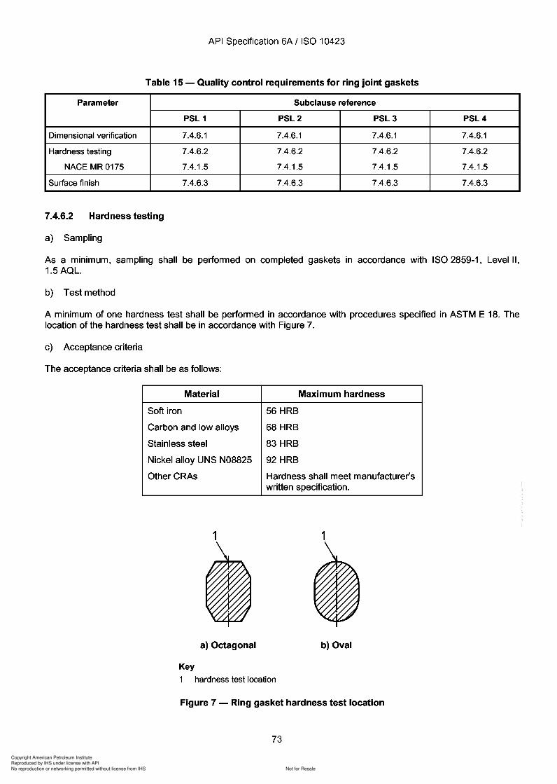
73
Copyright American Petroleum Institute
Reproduced by IHS under license with API
Not for ResaleNo reproduction or networking permitted without license from IHS
--`,,`,`,-`-`,,`,,`,`,,`---
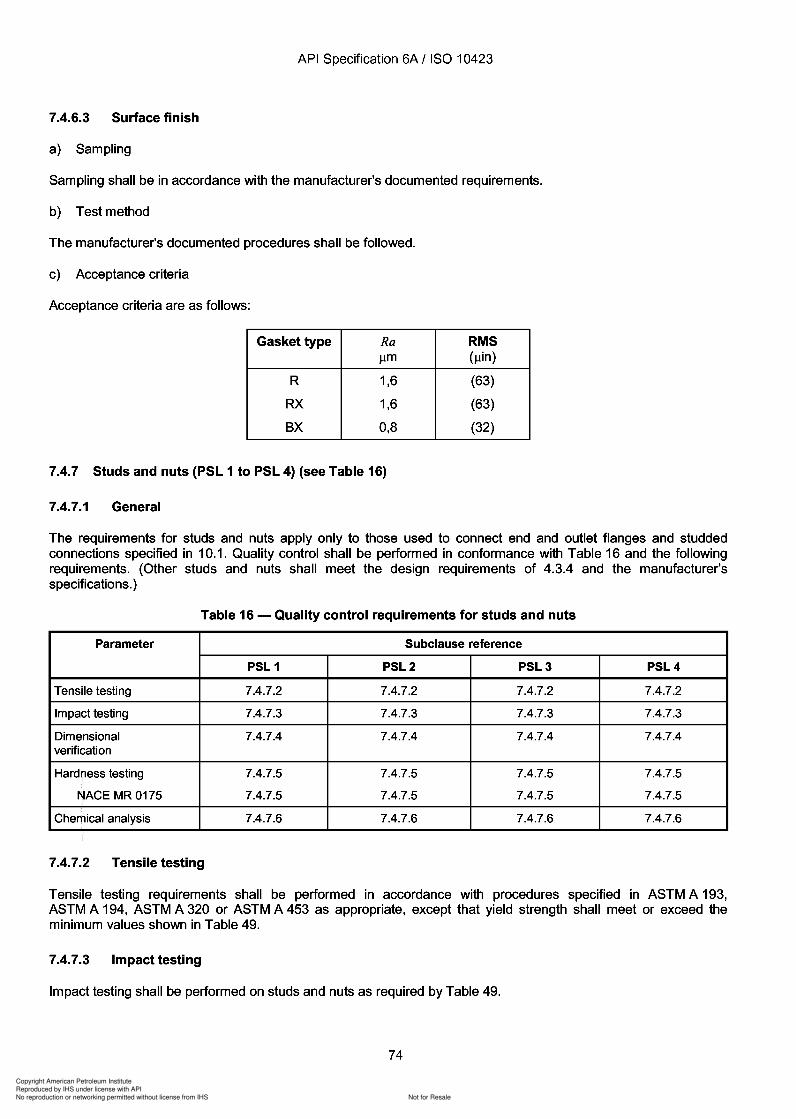
Copyright American Petroleum Institute
Reproduced by IHS under license with API
Not for ResaleNo reproduction or networking permitted without license from IHS
--`,,`,`,-`-`,,`,,`,`,,`---
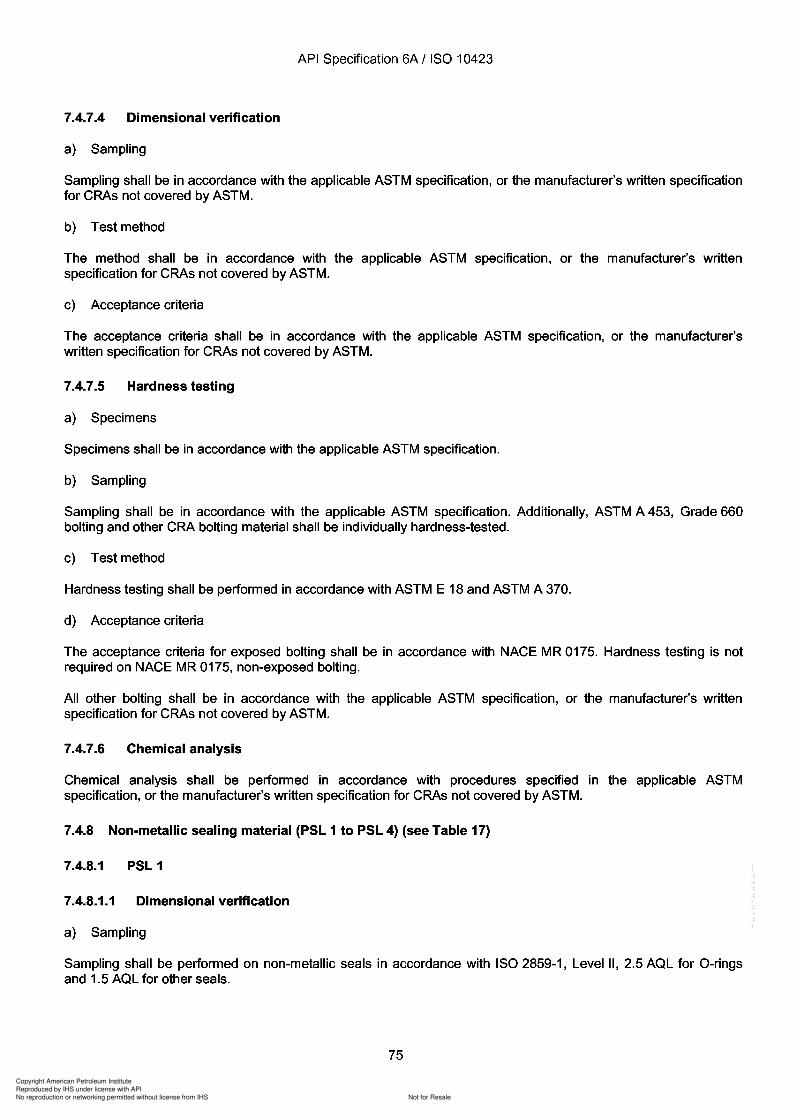
Copyright American Petroleum Institute
Reproduced by IHS under license with API
Not for ResaleNo reproduction or networking permitted without license from IHS
--`,,`,`,-`-`,,`,,`,`,,`---
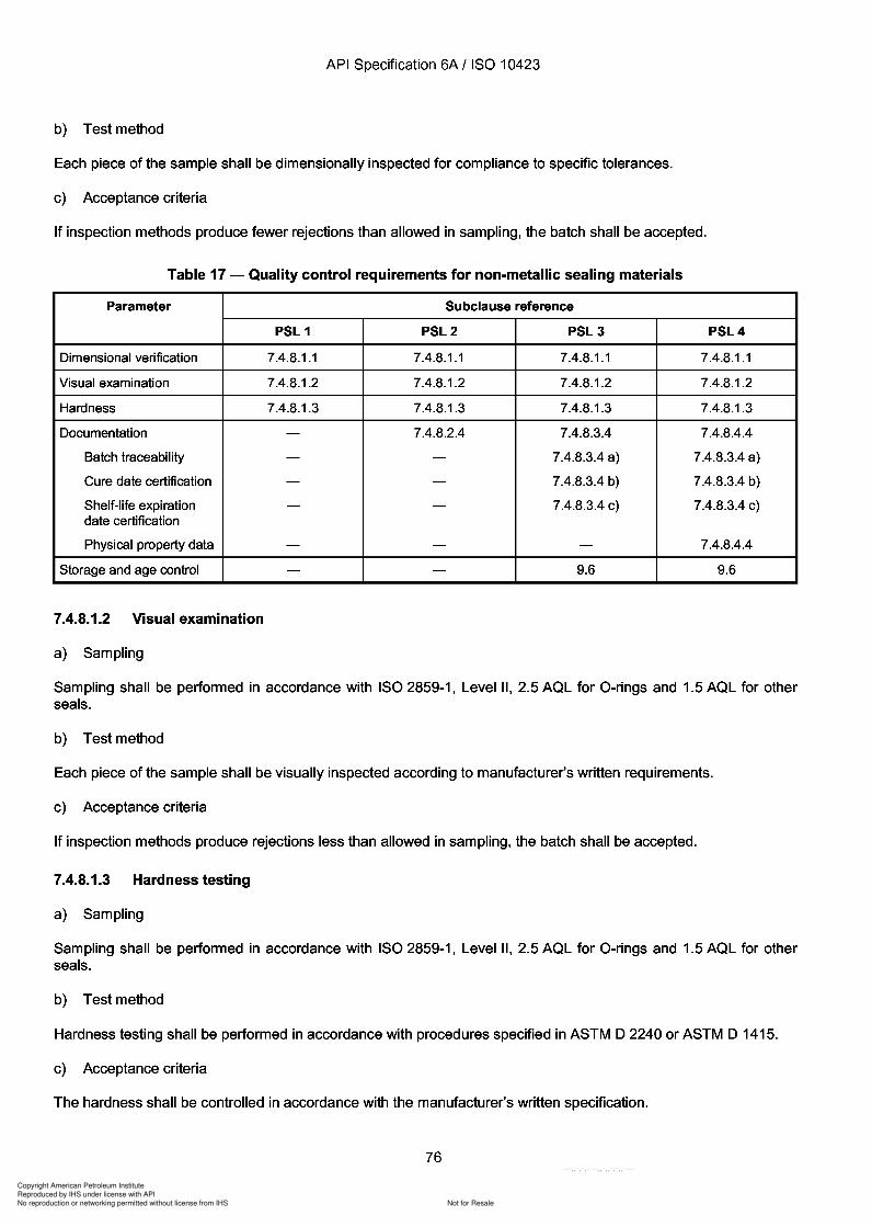
Copyright American Petroleum Institute
Reproduced by IHS under license with API
Not for ResaleNo reproduction or networking permitted without license from IHS
--`,,`,`,-`-`,,`,,`,`,,`---
API Specification 6A / ISO 10423
b) Test method
Each piece of the sample shall be dimensionally inspected for compliance to specific tolerances.
c) Acceptance criteria
If inspection methods produce fewer rejections than allowed in sampling, the batch shall be accepted.
Table 17 - Quality control requirements for non-metallic sealing materials
Parameter Subclause reference
PSL 1 PSL2 PSL3 PSL4
Dimensional verification 7.4.8.1.1 7.4.8.1.1 7.4.8.1.1 7.4.8.1.1
Visual examination 7.4.8.1.2 7.4.8.1.2 7.4.8.1.2 7.4.8.1.2
Hardness 7.4.8.1.3 7.4.8.1.3 7.4.8.1.3 7.4.8.1.3
Documentation - 7.4.8.2.4 7.4.8.3.4 7.4.8.4.4
Batch traceability - - 7.4.8.3.4 a) 7.4.8.3.4 a)
Cure date certification - - 7.4.8.3.4 b) 7.4.8.3.4 b)
Shelf-life expiration - - 7.4.8.3.4 c) 7.4.8.3.4 c)date certification
Physical property data - - - 7.4.8.4.4
Storage and age control - - 9.6 9.6
7.4.8.1.2 Visual examination
a) Sampling
Sampling shall be performed in accordance with ISO 2859-1, Level II, 2.5 AQL for a-rings and 1.5 AQL for otherseals.
b) Test method
Each piece of the sample shall be visually inspected according to manufacturer's written requirements.
c) Acceptance criteria
If inspection methods produce rejections less than allowed in sampling, the batch shall be accepted.
7.4.8.1.3 Hardness testing
a) Sampling
Sampling shall be performed in accordance with ISO 2859-1, Level II, 2.5 AQL for a-rings and 1.5 AQL for otherseals.
b) Test method
Hardness testing shall be performed in accordance with procedures specified in ASTM D 2240 or ASTM D 1415.
c) Acceptance criteria
The hardness shall be controlled in accordance with the manufacturer's written specification.
76
API Specification 6A / ISO 10423
b) Test method
Each piece of the sample shall be dimensionally inspected for compliance to specific tolerances.
c) Acceptance criteria
If inspection methods produce fewer rejections than allowed in sampling, the batch shall be accepted.
Table 17 - Quality control requirements for non-metallic sealing materials
Parameter Subclause reference
PSL 1 PSL2 PSL3 PSL4
Dimensional verification 7.4.8.1.1 7.4.8.1.1 7.4.8.1.1 7.4.8.1.1
Visual examination 7.4.8.1.2 7.4.8.1.2 7.4.8.1.2 7.4.8.1.2
Hardness 7.4.8.1.3 7.4.8.1.3 7.4.8.1.3 7.4.8.1.3
Documentation - 7.4.8.2.4 7.4.8.3.4 7.4.8.4.4
Batch traceability - - 7.4.8.3.4 a) 7.4.8.3.4 a)
Cure date certification - - 7.4.8.3.4 b) 7.4.8.3.4 b)
Shelf-life expiration - - 7.4.8.3.4 c) 7.4.8.3.4 c) date certification
Physical property data - - - 7.4.8.4.4
Storage and age control - - 9.6 9.6
7.4.8.1.2 Visual examination
a) Sampling
Sampling shall be performed in accordance with ISO 2859-1, Level II, 2.5 AQL for O-rings and 1.5 AQL for other seals.
b) Test method
Each piece of the sample shall be visually inspected according to manufacturer's written requirements.
c) Acceptance criteria
If inspection methods produce rejections less than allowed in sampling, the batch shall be accepted.
7.4.8.1.3 Hardness testing
a) Sampling
Sampling shall be performed in accordance with ISO 2859-1, Level II, 2.5 AQL for O-rings and 1.5 AQL for other seals.
b) Test method
Hardness testing shall be performed in accordance with procedures specified in ASTM D 2240 or ASTM D 1415.
c) Acceptance criteria
The hardness shall be controlled in accordance with the manufacturer's written specification.
76
Copyright American Petroleum Institute
Reproduced by IHS under license with API
Not for ResaleNo reproduction or networking permitted without license from IHS
--`,,`,`,-`-`,,`,,`,`,,`---
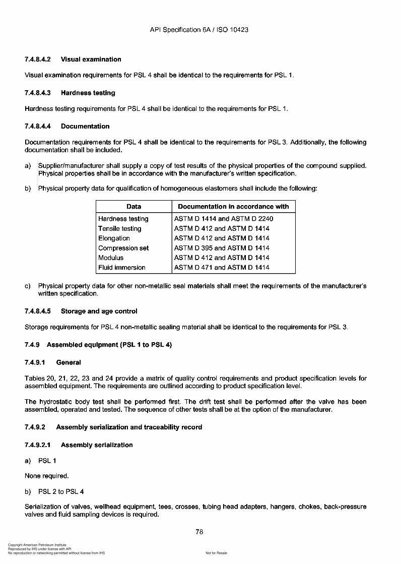
Copyright American Petroleum Institute
Reproduced by IHS under license with API
Not for ResaleNo reproduction or networking permitted without license from IHS
--`,,`,`,-`-`,,`,,`,`,,`---
Copyright American Petroleum Institute
Reproduced by IHS under license with API
Not for ResaleNo reproduction or networking permitted without license from IHS
--`,,`,`,-`-`,,`,,`,`,,`---
API Specification 6A / ISO 10423
7.4.9.2.2 Traceability record
a) PSL 1 and PSL 2
None required.
b) PSL 3 and PSL 4
A report identifying the body, bonnet, stem, end and out outlet connection, and valve-bore sealing mechanismsshall be listed traceable to the assembly.
7.4.9.3 PSL 1 testing
7.4.9.3.1 Drift test - Full-bore valves
a) Test method
Pass a drift mandrel as described in Table 18 through the valve bore after the valve has been assembled, operatedand pressure-tested.
b) Acceptance criteria
The drift mandrel shall pass completely through the valve bore.
7.4.9.3.2 Drift test - Christmas trees (see Table 18)
a) Test method
Pass a drift mandrel through the main bore of christmas tree assemblies.
b) Acceptance criteria
The drift mandrel shall completely pass through the main bore of the christmas tree.
7.4.9.3.3 Hydrostatic body test -Individual equipment
a) Test method
Subject assembled equipment to a hydrostatic body test prior to shipment from the manufacturer's facility. Thehydrostatic body test shall be the first pressure test performed. Do not apply test pressure as a differential pressureacross closure mechanisms of valves. Use water or water with additives as the testing fluid. Complete tests prior topainting; however if the bodies and other pressure-containing parts have been made of wrought material, tests maybe completed after painting.
Loose connectors, bullplugs and valve-removal plugs do not require a hydrostatic test.
The hydrostatic body test for assembled equipment shall consist of three parts:
the primary pressure-holding period;
the reduction of the pressure to zero;
the secondary pressure-holding period.
Conduct tests prior to the addition of body-filler grease. Lubrication applied during assembly is acceptable.
Both pressure-holding periods shall not be less than 3 min; do not start the timing until the test pressure has beenreached, the equipment and the pressure-monitoring gauge have been isolated from the pressure source, and theexternal surfaces of the body members have been thoroughly dried.
Determine the hydrostatic body test pressure by the rated working pressure of the equipment. Hydrostatic testpressures shall be as given in Table 19.
79
API Specification 6A / ISO 10423
7.4.9.2.2 Traceability record
a) PSL 1 and PSL 2
None required.
b) PSL 3 and PSL 4
A report identifying the body, bonnet, stem, end and out outlet connection, and valve-bore sealing mechanisms shall be listed traceable to the assembly.
7.4.9.3 PSL 1 testing
7.4.9.3.1 Drift test - Full-bore valves
a) Test method
Pass a drift mandrel as described in Table 18 through the valve bore after the valve has been assembled, operated and pressure-tested.
b) Acceptance criteria
The drift mandrel shall pass completely through the valve bore.
7.4.9.3.2 Drift test - Christmas trees (see Table 18)
a) Test method
Pass a drift mandrel through the main bore of christmas tree assemblies.
b) Acceptance criteria
The drift mandrel shall completely pass through the main bore of the christmas tree.
7.4.9.3.3 Hydrostatic body test -Individual equipment
a) Test method
Subject assembled equipment to a hydrostatic body test prior to shipment from the manufacturer's facility. The hydrostatic body test shall be the first pressure test performed. Do not apply test pressure as a differential pressure across closure mechanisms of valves. Use water or water with additives as the testing fluid. Complete tests prior to painting; however if the bodies and other pressure-containing parts have been made of wrought material, tests may be completed after painting.
Loose connectors, bullplugs and valve-removal plugs do not require a hydrostatic test.
The hydrostatic body test for assembled equipment shall consist of three parts:
the primary pressure-holding period;
the reduction of the pressure to zero;
the secondary pressure-holding period.
Conduct tests prior to the addition of body-filler grease. Lubrication applied during assembly is acceptable.
Both pressure-holding periods shall not be less than 3 min; do not start the timing until the test pressure has been reached, the equipment and the pressure-monitoring gauge have been isolated from the pressure source, and the external surfaces of the body members have been thoroughly dried.
Determine the hydrostatic body test pressure by the rated working pressure of the equipment. Hydrostatic test pressures shall be as given in Table 19.
79
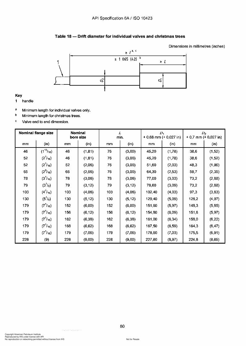
Copyright American Petroleum Institute
Reproduced by IHS under license with API
Not for ResaleNo reproduction or networking permitted without license from IHS
--`,,`,`,-`-`,,`,,`,`,,`---
API Specification 6A / ISO 10423
Table 18 - Drift diameter for individual valves and christmas trees
Dimensions in millimetres (inches)> I a. c-
~ 1 065 (42) b~ L
N
~t:::l
1
~Key
1 handle
a
b
c
Minimum length for individual valves only.
Minimum length for christmas trees.
Valve end to end dimension.
Nominal flange size Nominal L D1 D2bore size min. + 0,68 mm (+ 0,027 in) + 0,7 mm (+ 0,027 in)
mm (in) mm (in) mm (in) mm (in) mm (in)
46 (1 13/16) 46 (1,81 ) 76 (3,00) 45,20 (1,78) 38,6 (1,52)
52 (21/16) 46 (1,81 ) 76 (3,00) 45,20 (1,78) 38,6 (1,52)
52 (21/16) 52 (2,06) 76 (3,00) 51,60 (2,03) 48,3 (1,90)
65 (29/16) 65 (2,56) 76 (3,00) 64,30 (2,53) 59,7 (2,35)
78 (31/16) 78 (3,06) 78 (3,06) 77,00 (3,03) 73,2 (2,88)
79 (31/8) 79 (3,12) 79 (3,12) 78,60 (3,09) 73,2 (2,88)
103 (41/16) 103 (4,06) 103 (4,06) 102,40 (4,03) 97,3 (3,83)
130 (51/8) 130 (5,12) 130 (5,12) 129,40 (5,09) 126,2 (4,97)
179 (71/16) 152 (6,00) 152 (6,00) 151,60 (5,97) 148,3 (5,85)
179 (71/16) 156 (6,12) 156 (6,12) 154,80 (6,09) 151,6 (5,97)
179 (71/16) 162 (6,38) 162 (6,38) 161,00 (6,34) 158,0 (6,22)
179 (71/16) 168 (6,62) 168 (6,62) 167,50 (6,59) 164,3 (6,47)
179 (71/16) 179 (7,06) 179 (7,06) 178,60 (7,03) 175,5 (6,91 )
228 (9) 228 (9,00) 228 (9,00) 227,80 (8,97) 224,8 (8,85)
80
API Specification 6A / ISO 10423
Table 18 - Drift diameter for individual valves and christmas trees
Dimensions in millimetres (inches)
Key
1
a
b
c
1
~ handle
Minimum length for individual valves only.
Minimum length for christmas trees.
Valve end to end dimension.
Nominal flange size Nominal bore size
mm (in) mm (in)
46 (1 13/16) 46 (1,81 )
52 (21/16) 46 (1,81 )
52 (21/16) 52 (2,06)
65 (29/16) 65 (2,56)
78 (31/16) 78 (3,06)
79 (31/8) 79 (3,12)
103 (41/16) 103 (4,06)
130 (51/8) 130 (5,12)
179 (71/16) 152 (6,00)
179 (71/16) 156 (6,12)
179 (71/16) 162 (6,38)
179 (71/16) 168 (6,62)
179 (71/16) 179 (7,06)
228 (9) 228 (9,00)
N
t:::l
mm
76
76
76
76
78
79
103
130
152
156
162
168
179
228
> I a, C -~ 1 065 (42) b
~ L
~
L D1 D2 min. + 0,68 mm (+ 0,027 in) + 0,7 mm (+ 0,027 in)
(in) mm (in) mm (in)
(3,00) 45,20 (1,78) 38,6 (1,52)
(3,00) 45,20 (1,78) 38,6 (1,52)
(3,00) 51,60 (2,03) 48,3 (1,90)
(3,00) 64,30 (2,53) 59,7 (2,35)
(3,06) 77,00 (3,03) 73,2 (2,88)
(3,12) 78,60 (3,09) 73,2 (2,88)
(4,06) 102,40 (4,03) 97,3 (3,83)
(5,12) 129,40 (5,09) 126,2 (4,97)
(6,00) 151,60 (5,97) 148,3 (5,85)
(6,12) 154,80 (6,09) 151,6 (5,97)
(6,38) 161,00 (6,34) 158,0 (6,22)
(6,62) 167,50 (6,59) 164,3 (6,47)
(7,06) 178,60 (7,03) 175,5 (6,91 )
(9,00) 227,80 (8,97) 224,8 (8,85)
80
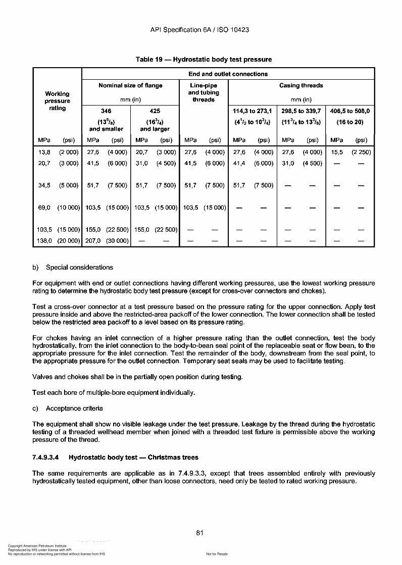
Copyright American Petroleum Institute
Reproduced by IHS under license with API
Not for ResaleNo reproduction or networking permitted without license from IHS
--`,,`,`,-`-`,,`,,`,`,,`---
API Specification 6A / ISO 10423
Table 19 - Hydrostatic body test pressure
End and outlet connections
Nominal size of flange Line-pipe Casing threadsWorking and tubingpressure mm (in) threads mm (in)
rating 346 425 114,3 to 273,1 298,5 to 339,7 406,5 to 508,0
(13%) (163/4) (41/2 to 103/4) (11 3/4 to 13%) (16 to 20)and smaller and larger
MPa (psi) MPa (psi) MPa (psi) MPa (psi) MPa (psi) MPa (psi) MPa (psi)
13,8 (2000) 27,6 (4000) 20,7 (3000) 27,6 (4000) 27,6 (4000) 27,6 (4000) 15,5 (2250)
20,7 (3000) 41,5 (6000) 31,0 (4500) 41,5 (6000) 41,4 (6000) 31,0 (4500) - -
34,5 (5000) 51,7 (7500) 51,7 (7500) 51,7 (7500) 51,7 (7500) - - - -
69,0 (10 000) 103,5 (15000) 103,5 (15000) 103,5 (15000) - - - - - -
103,5 (15000) 155,0 (22500) 155,0 (22500) - - - - - - - -138,0 (20000) 207,0 (30000) - - - - - - - - - -
b) Special considerations
For equipment with end or outlet connections having different working pressures, use the lowest working pressurerating to determine the hydrostatic body test pressure (except for cross-over connectors and chokes).
Test a cross-over connector at a test pressure based on the pressure rating for the upper connection. Apply testpressure inside and above the restricted-area packoff of the lower connection. The lower connection shall be testedbelow the restricted area packoff to a level based on its pressure rating.
For chokes having an inlet connection of a higher pressure rating than the outlet connection, test the bodyhydrostatically, from the inlet connection to the body-to-bean seal point of the replaceable seat or flow bean, to theappropriate pressure for the inlet connection. Test the remainder of the body, downstream from the seal point, tothe appropriate pressure for the outlet connection. Temporary seat seals may be used to facilitate testing.
Valves and chokes shall be in the partially open position during testing.
Test each bore of multiple-bore equipment individually.
c) Acceptance criteria
The equipment shall show no visible leakage under the test pressure. Leakage by the thread during the hydrostatictesting of a threaded wellhead member when joined with a threaded test fixture is permissible above the workingpressure of the thread.
7.4.9.3.4 Hydrostatic body test - Christmas trees
The same requirements are applicable as in 7.4.9.3.3, except that trees assembled entirely with previouslyhydrostatically tested equipment, other than loose connectors, need only be tested to rated working pressure.
81
API Specification 6A / ISO 10423
Table 19 - Hydrostatic body test pressure
End and outlet connections
Nominal size of flange Line-pipe Casing threads Working and tubing pressure mm (in) threads mm (in)
rating 346 425 114,3 to 273,1 298,5 to 339,7 406,5 to 508,0
(13%) (163/4) (41/2 to 103/4) (11 3/4 to 13%) (16 to 20) and smaller and larger
MPa (psi) MPa (psi) MPa (psi) MPa (psi) MPa (psi) MPa (psi) MPa (psi)
13,8 (2000) 27,6 (4000) 20,7 (3000) 27,6 (4000) 27,6 (4000) 27,6 (4000) 15,5 (2250)
20,7 (3000) 41,5 (6000) 31,0 (4500) 41,5 (6000) 41,4 (6000) 31,0 (4500) - -
34,5 (5000) 51,7 (7500) 51,7 (7500) 51,7 (7500) 51,7 (7500) - - - -
69,0 (10 000) 103,5 (15000) 103,5 (15000) 103,5 (15000) - - - - - -
103,5 (15000) 155,0 (22500) 155,0 (22500) - - - - - - - -138,0 (20000) 207,0 (30000) - - - - - - - - - -
b) Special considerations
For equipment with end or outlet connections having different working pressures, use the lowest working pressure rating to determine the hydrostatic body test pressure (except for cross-over connectors and chokes).
Test a cross-over connector at a test pressure based on the pressure rating for the upper connection. Apply test pressure inside and above the restricted-area packoff of the lower connection. The lower connection shall be tested below the restricted area packoff to a level based on its pressure rating.
For chokes having an inlet connection of a higher pressure rating than the outlet connection, test the body hydrostatically, from the inlet connection to the body-to-bean seal point of the replaceable seat or flow bean, to the appropriate pressure for the inlet connection. Test the remainder of the body, downstream from the seal point, to the appropriate pressure for the outlet connection. Temporary seat seals may be used to facilitate testing.
Valves and chokes shall be in the partially open position during testing.
Test each bore of multiple-bore equipment individually.
c) Acceptance criteria
The equipment shall show no visible leakage under the test pressure. Leakage by the thread during the hydrostatic testing of a threaded wellhead member when joined with a threaded test fixture is permissible above the working pressure of the thread.
7.4.9.3.4 Hydrostatic body test - Christmas trees
The same requirements are applicable as in 7.4.9.3.3, except that trees assembled entirely with previously hydrostatically tested equipment, other than loose connectors, need only be tested to rated working pressure.
81
Copyright American Petroleum Institute
Reproduced by IHS under license with API
Not for ResaleNo reproduction or networking permitted without license from IHS
--`,,`,`,-`-`,,`,,`,`,,`---
API Specification 6A / ISO 10423
7.4.9.3.5 Hydrostatic seat test - Valves
a) Test method
For bidirectional valves, apply hydrostatic seat test pressure, equal to the rated working pressure, to each side ofthe gate or plug with the other side open to atmosphere.
For unidirectional valves, apply pressure in the direction indicated on the body, except for check valves which shallbe tested on the downstream side.
Holding periods for tests shall be a minimum of 3 min.
Reduce the pressure to zero between all holding periods.
Test valves a minimum of two times on each side of the gate or plug.
b) Acceptance criteria
No visible leakage shall occur during each holding period.
7.4.9.4 PSL 2 testing
7.4.9.4.1 Drift test - Full-bore valves
Drift test requirements for PSL 2 shall be identical to the requirements for PSL 1.
7.4.9.4.2 Drift test - Christmas trees
Drift test requirements for PSL 2 shall be identical to the requirements for PSL 1.
7.4.9.4.3 Hydrostatic body test - Individual equipment
Hydrostatic body test requirements for PSL 2 shall be identical to the requirements for PSL 1.
7.4.9.4.4 Hydrostatic body test - Christmas trees
Hydrostatic body test requirements for PSL 2 shall be identical to the requirements for PSL 1.
7.4.9.4.5 Hydrostatic seat test - Valves
a) Test method
Apply the hydrostatic seat test pressure, which is equal to the rated working pressure, to one side of the gate orplug of the valve with the other side open to atmosphere. Test bidirectional valves in both directions. Testunidirectional valves in the direction indicated on the body, except for check valves which shall be tested from thedownstream side.
After the pressure has been applied to one side of the gate or plug, hold the pressure and monitor for a minimum of3min.
Then open the valve, except for check valves, while under full differential pressure.
Repeat the above two steps.
Then pressurize one side of the gate or plug, hold, and monitor a third time for a minimum of 3 min.
Next test bidirectional valves on the other side of the gate or plug using the same procedure outlined above. Splitgate valves may have both seats tested simultaneously.
82
API Specification 6A / ISO 10423
7.4.9.3.5 Hydrostatic seat test - Valves
a) Test method
For bidirectional valves, apply hydrostatic seat test pressure, equal to the rated working pressure, to each side of the gate or plug with the other side open to atmosphere.
For unidirectional valves, apply pressure in the direction indicated on the body, except for check valves which shall be tested on the downstream side.
Holding periods for tests shall be a minimum of 3 min.
Reduce the pressure to zero between all holding periods.
Test valves a minimum of two times on each side of the gate or plug.
b) Acceptance criteria
No visible leakage shall occur during each holding period.
7.4.9.4 PSL 2 testing
7.4.9.4.1 Drift test - Full-bore valves
Drift test requirements for PSL 2 shall be identical to the requirements for PSL 1.
7.4.9.4.2 Drift test - Christmas trees
Drift test requirements for PSL 2 shall be identical to the requirements for PSL 1.
7.4.9.4.3 Hydrostatic body test - Individual equipment
Hydrostatic body test requirements for PSL 2 shall be identical to the requirements for PSL 1.
7.4.9.4.4 Hydrostatic body test - Christmas trees
Hydrostatic body test requirements for PSL 2 shall be identical to the requirements for PSL 1.
7.4.9.4.5 Hydrostatic seat test - Valves
a) Test method
Apply the hydrostatic seat test pressure, which is equal to the rated working pressure, to one side of the gate or plug of the valve with the other side open to atmosphere. Test bidirectional valves in both directions. Test unidirectional valves in the direction indicated on the body, except for check valves which shall be tested from the downstream side.
After the pressure has been applied to one side of the gate or plug, hold the pressure and monitor for a minimum of 3min.
Then open the valve, except for check valves, while under full differential pressure.
Repeat the above two steps.
Then pressurize one side of the gate or plug, hold, and monitor a third time for a minimum of 3 min.
Next test bidirectional valves on the other side of the gate or plug using the same procedure outlined above. Splitgate valves may have both seats tested simultaneously.
82
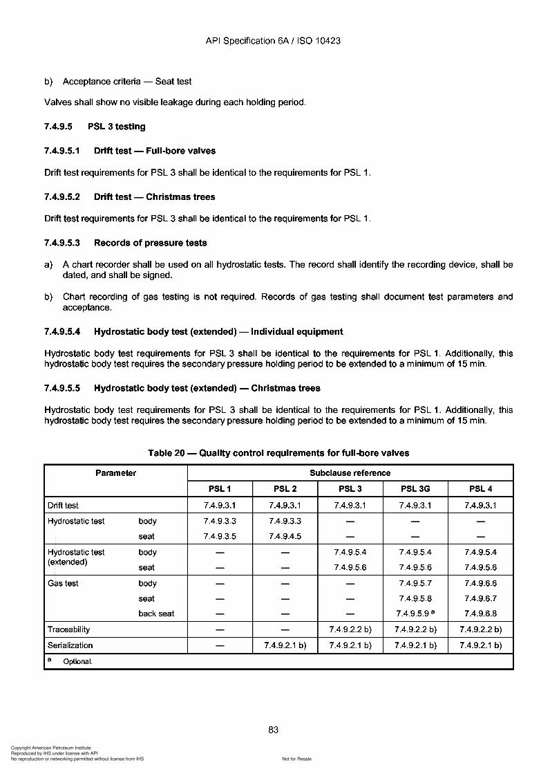
83
Copyright American Petroleum Institute
Reproduced by IHS under license with API
Not for ResaleNo reproduction or networking permitted without license from IHS
--`,,`,`,-`-`,,`,,`,`,,`---
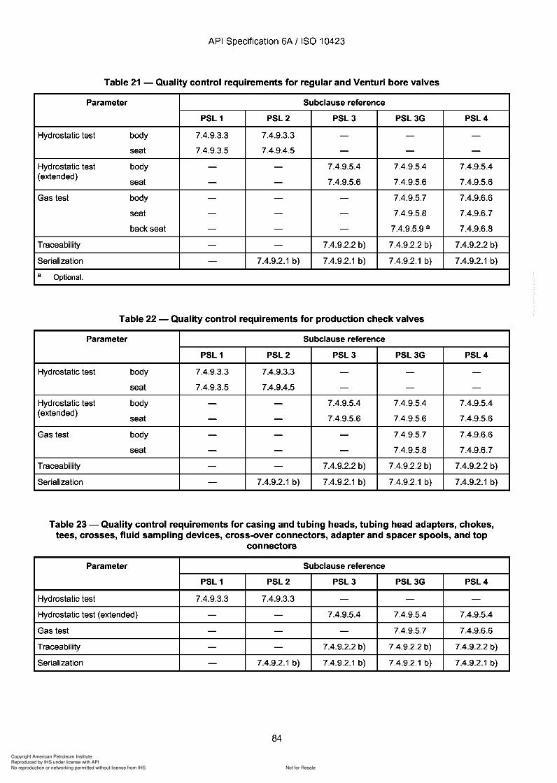
Copyright American Petroleum Institute
Reproduced by IHS under license with API
Not for ResaleNo reproduction or networking permitted without license from IHS
--`,,`,`,-`-`,,`,,`,`,,`---
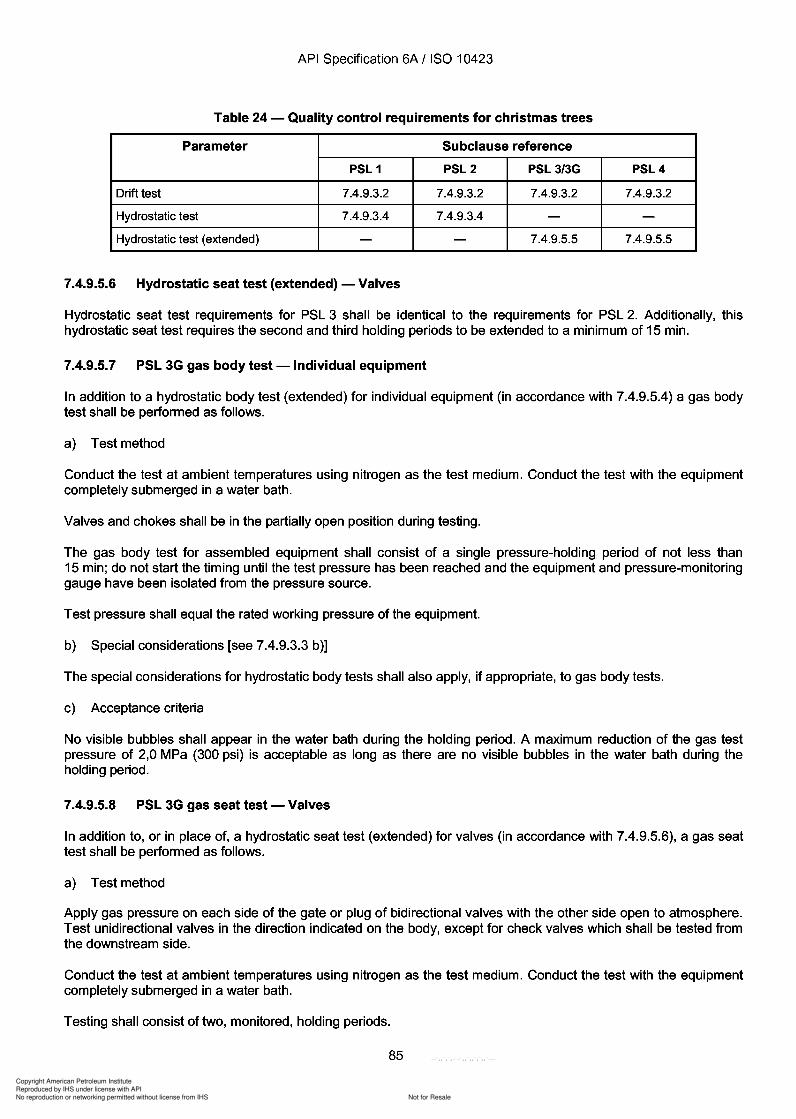
2 4
Copyright American Petroleum Institute
Reproduced by IHS under license with API
Not for ResaleNo reproduction or networking permitted without license from IHS
--`,,`,`,-`-`,,`,,`,`,,`---
API Specification 6A / ISO 10423
Table 24 - Quality control requirements for christmas trees
Parameter Subclause reference
PSL 1 PSL2 PSL 3/3G PSL4
Drift test 7.4.9.3.2 7.4.9.3.2 7.4.9.3.2 7.4.9.3.2
Hydrostatic test 7.4.9.3.4 7.4.9.3.4 - -Hydrostatic test (extended) - - 7.4.9.5.5 7.4.9.5.5
7.4.9.5.6 Hydrostatic seat test (extended) - Valves
Hydrostatic seat test requirements for PSL 3 shall be identical to the requirements for PSL 2. Additionally, thishydrostatic seat test requires the second and third holding periods to be extended to a minimum of 15 min.
7.4.9.5.7 PSL 3G gas body test -Individual equipment
In addition to a hydrostatic body test (extended) for individual equipment (in accordance with 7.4.9.5.4) a gas bodytest shall be performed as follows.
a) Test method
Conduct the test at ambient temperatures using nitrogen as the test medium. Conduct the test with the equipmentcompletely submerged in a water bath.
Valves and chokes shall be in the partially open position during testing.
The gas body test for assembled equipment shall consist of a single pressure-holding period of not less than15 min; do not start the timing until the test pressure has been reached and the equipment and pressure-monitoringgauge have been isolated from the pressure source.
Test pressure shall equal the rated working pressure of the equipment.
b) Special considerations [see 7.4.9.3.3 b)]
The special considerations for hydrostatic body tests shall also apply, if appropriate, to gas body tests.
c) Acceptance criteria
No visible bubbles shall appear in the water bath during the holding period. A maximum reduction of the gas testpressure of 2,0 MPa (300 psi) is acceptable as long as there are no visible bubbles in the water bath during theholding period.
7.4.9.5.8 PSL 3G gas seat test - Valves
In addition to, or in place of, a hydrostatic seat test (extended) for valves (in accordance with 7.4.9.5.6), a gas seattest shall be performed as follows.
a) Test method
Apply gas pressure on each side of the gate or plug of bidirectional valves with the other side open to atmosphere.Test unidirectional valves in the direction indicated on the body, except for check valves which shall be tested fromthe downstream side.
Conduct the test at ambient temperatures using nitrogen as the test medium. Conduct the test with the equipmentcompletely submerged in a water bath.
Testing shall consist of two, monitored, holding periods.
85
API Specification 6A / ISO 10423
Table 24 - Quality control requirements for christmas trees
Parameter Subclause reference
PSL 1 PSL2 PSL 3/3G PSL4
Drift test 7.4.9.3.2 7.4.9.3.2 7.4.9.3.2 7.4.9.3.2
Hydrostatic test 7.4.9.3.4 7.4.9.3.4 - -Hydrostatic test (extended) - - 7.4.9.5.5 7.4.9.5.5
7.4.9.5.6 Hydrostatic seat test (extended) - Valves
Hydrostatic seat test requirements for PSL 3 shall be identical to the requirements for PSL 2. Additionally, this hydrostatic seat test requires the second and third holding periods to be extended to a minimum of 15 min.
7.4.9.5.7 PSL 3G gas body test -Individual equipment
In addition to a hydrostatic body test (extended) for individual equipment (in accordance with 7.4.9.5.4) a gas body test shall be performed as follows.
a) Test method
Conduct the test at ambient temperatures using nitrogen as the test medium. Conduct the test with the equipment completely submerged in a water bath.
Valves and chokes shall be in the partially open position during testing.
The gas body test for assembled equipment shall consist of a single pressure-holding period of not less than 15 min; do not start the timing until the test pressure has been reached and the equipment and pressure-monitoring gauge have been isolated from the pressure source.
Test pressure shall equal the rated working pressure of the equipment.
b) Special considerations [see 7.4.9.3.3 b)]
The special considerations for hydrostatic body tests shall also apply, if appropriate, to gas body tests.
c) Acceptance criteria
No visible bubbles shall appear in the water bath during the holding period. A maximum reduction of the gas test pressure of 2,0 MPa (300 psi) is acceptable as long as there are no visible bubbles in the water bath during the holding period.
7.4.9.5.8 PSL 3G gas seat test - Valves
In addition to, or in place of, a hydrostatic seat test (extended) for valves (in accordance with 7.4.9.5.6), a gas seat test shall be performed as follows.
a) Test method
Apply gas pressure on each side of the gate or plug of bidirectional valves with the other side open to atmosphere. Test unidirectional valves in the direction indicated on the body, except for check valves which shall be tested from the downstream side.
Conduct the test at ambient temperatures using nitrogen as the test medium. Conduct the test with the equipment completely submerged in a water bath.
Testing shall consist of two, monitored, holding periods.
85
Copyright American Petroleum Institute
Reproduced by IHS under license with API
Not for ResaleNo reproduction or networking permitted without license from IHS
--`,,`,`,-`-`,,`,,`,`,,`---
API Specification 6A / ISO 10423
The primary test pressure shall be the rated working pressure.
The primary-test monitored holding period shall be a minimum of 15 min.
Reduce the pressure to zero between the primary and secondary holding periods.
The secondary test pressure shall be at 2,0 MPa (300 psi) ± 10 %.
The secondary-test monitored holding period shall be a minimum of 15 min.
The valves shall be fully opened and fully closed between tests.
Next, test bidirectional valves on the other side of the gate or plug using the same procedure outlined above. Splitgate valves may have both seats tested simultaneously.
b) Acceptance criteria
No visible bubbles shall appear in the water bath during the holding periods. A maximum reduction of the gas testpressure of 2,0 MPa (300 psi) is acceptable as long as there are no visible bubbles in the water bath during theholding period.
7.4.9.5.9 PSL 3G gas back-seat test - Gate valves
A gas back-seat test may be performed on gate valves. A gas back-seat test shall be used in conjunction with thegas body test - individual equipment (see 7.4.9.5.7) and the gas seat test for valves (see 7.4.9.5.8).
a) Test method
Conduct the test at ambient temperatures using nitrogen as the test medium. Conduct the test with the equipmentcompletely submerged in a water bath.
The area between the primary packing and the back seat, or other means for repacking the stuffing box, shall bevented during the test.
The test shall consist of one holding period.
The monitored holding period shall be at the rated working pressure.
The monitored holding period shall be a minimum of 15 min.
b) Acceptance criteria
No visible bubbles shall appear in the water bath during the holding period. A maximum reduction of the gas testpressure of 2,0 MPa (300 psi) is acceptable as long as there are no visible bubbles in the water bath during theholding period.
7.4.9.6 PSL 4 testing
7.4.9.6.1 Drift test - Full-bore valves
Drift test requirements for PSL 4 shall be identical to the requirements for PSL 1.
7.4.9.6.2 Drift test - Christmas trees
Drift test requirements for PSL 4 shall be identical to the requirements for PSL 1.
86
API Specification 6A / ISO 10423
The primary test pressure shall be the rated working pressure.
The primary-test monitored holding period shall be a minimum of 15 min.
Reduce the pressure to zero between the primary and secondary holding periods.
The secondary test pressure shall be at 2,0 MPa (300 psi) ± 10 %.
The secondary-test monitored holding period shall be a minimum of 15 min.
The valves shall be fully opened and fully closed between tests.
Next, test bidirectional valves on the other side of the gate or plug using the same procedure outlined above. Splitgate valves may have both seats tested simultaneously.
b) Acceptance criteria
No visible bubbles shall appear in the water bath during the holding periods. A maximum reduction of the gas test pressure of 2,0 MPa (300 psi) is acceptable as long as there are no visible bubbles in the water bath during the holding period.
7.4.9.5.9 PSL 3G gas back-seat test - Gate valves
A gas back-seat test may be performed on gate valves. A gas back-seat test shall be used in conjunction with the gas body test - individual equipment (see 7.4.9.5.7) and the gas seat test for valves (see 7.4.9.5.8).
a) Test method
Conduct the test at ambient temperatures using nitrogen as the test medium. Conduct the test with the equipment completely submerged in a water bath.
The area between the primary packing and the back seat, or other means for repacking the stuffing box, shall be vented during the test.
The test shall consist of one holding period.
The monitored holding period shall be at the rated working pressure.
The monitored holding period shall be a minimum of 15 min.
b) Acceptance criteria
No visible bubbles shall appear in the water bath during the holding period. A maximum reduction of the gas test pressure of 2,0 MPa (300 psi) is acceptable as long as there are no visible bubbles in the water bath during the holding period.
7.4.9.6 PSL 4 testing
7.4.9.6.1 Drift test - Full-bore valves
Drift test requirements for PSL 4 shall be identical to the requirements for PSL 1.
7.4.9.6.2 Drift test - Christmas trees
Drift test requirements for PSL 4 shall be identical to the requirements for PSL 1.
86
Copyright American Petroleum Institute
Reproduced by IHS under license with API
Not for ResaleNo reproduction or networking permitted without license from IHS
--`,,`,`,-`-`,,`,,`,`,,`---
Copyright American Petroleum Institute
Reproduced by IHS under license with API
Not for ResaleNo reproduction or networking permitted without license from IHS
--`,,`,`,-`-`,,`,,`,`,,`---
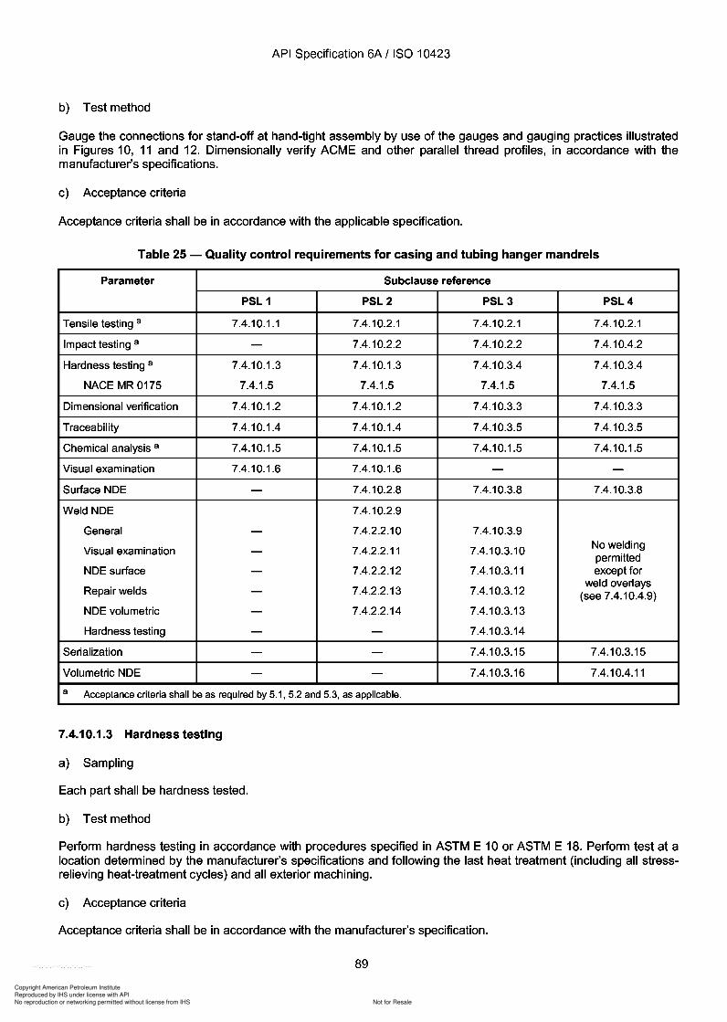
Copyright American Petroleum Institute
Reproduced by IHS under license with API
Not for ResaleNo reproduction or networking permitted without license from IHS
--`,,`,`,-`-`,,`,,`,`,,`---
API Specification 6A / ISO 10423
b) Test method
Gauge the connections for stand-off at hand-tight assembly by use of the gauges and gauging practices illustratedin Figures 10, 11 and 12. Dimensionally verify ACME and other parallel thread profiles, in accordance with themanufacturer's specifications.
c) Acceptance criteria
Acceptance criteria shall be in accordance with the applicable specification.
Table 25 - Quality control requirements for casing and tubing hanger mandrels
Parameter Subclause reference
PSL 1 PSL2 PSL3 PSL4
Tensile testing a 7.4.10.1.1 7.4.10.2.1 7.4.10.2.1 7.4.10.2.1
Impact testing a - 7.4.10.2.2 7.4.10.2.2 7.4.10.4.2
Hardness testing a 7.4.10.1.3 7.4.10.1.3 7.4.10.3.4 7.4.10.3.4
NACE MR0175 7.4.1.5 7.4.1.5 7.4.1.5 7.4.1.5
Dimensional verification 7.4.10.1.2 7.4.10.1.2 7.4.10.3.3 7.4.10.3.3
Traceability 7.4.10.1.4 7.4.10.1.4 7.4.10.3.5 7.4.10.3.5
Chemical analysis a 7.4.10.1.5 7.4.10.1.5 7.4.10.1.5 7.4.10.1.5
Visual examination 7.4.10.1.6 7.4.10.1.6 - -Surface NDE - 7.4.10.2.8 7.4.10.3.8 7.4.10.3.8
Weld NDE 7.4.10.2.9
General - 7.4.2.2.10 7.4.10.3.9
Visual examination - 7.4.2.2.11 7.4.10.3.10 No weldingpermitted
NDE surface - 7.4.2.2.12 7.4.10.3.11 except for
Repair welds 7.4.2.2.13 7.4.10.3.12weld overlays- (see 7.4.10.4.9)
NDE volumetric - 7.4.2.2.14 7.4.10.3.13
Hardness testing - - 7.4.10.3.14
Serialization - - 7.4.10.3.15 7.4.10.3.15
Volumetric NDE - - 7.4.10.3.16 7.4.10.4.11
a Acceptance criteria shall be as required by 5.1, 5.2 and 5.3, as applicable.
7.4.10.1.3 Hardness testing
a) Sampling
Each part shall be hardness tested.
b) Test method
Perform hardness testing in accordance with procedures specified in ASTM E 10 or ASTM E 18. Perform test at alocation determined by the manufacturer's specifications and following the last heat treatment (including all stressrelieving heat-treatment cycles) and all exterior machining.
c) Acceptance criteria
Acceptance criteria shall be in accordance with the manufacturer's specification.
89
API Specification 6A / ISO 10423
b) Test method
Gauge the connections for stand-off at hand-tight assembly by use of the gauges and gauging practices illustrated in Figures 10, 11 and 12. Dimensionally verify ACME and other parallel thread profiles, in accordance with the manufacturer's specifications.
c) Acceptance criteria
Acceptance criteria shall be in accordance with the applicable specification.
Table 25 - Quality control requirements for casing and tubing hanger mandrels
Parameter Subclause reference
PSL 1 PSL2 PSL3 PSL4
Tensile testing a 7.4.10.1.1 7.4.10.2.1 7.4.10.2.1 7.4.10.2.1
Impact testing a - 7.4.10.2.2 7.4.10.2.2 7.4.10.4.2
Hardness testing a 7.4.10.1.3 7.4.10.1.3 7.4.10.3.4 7.4.10.3.4
NACE MR0175 7.4.1.5 7.4.1.5 7.4.1.5 7.4.1.5
Dimensional verification 7.4.10.1.2 7.4.10.1.2 7.4.10.3.3 7.4.10.3.3
Traceability 7.4.10.1.4 7.4.10.1.4 7.4.10.3.5 7.4.10.3.5
Chemical analysis a 7.4.10.1.5 7.4.10.1.5 7.4.10.1.5 7.4.10.1.5
Visual examination 7.4.10.1.6 7.4.10.1.6 - -Surface NDE - 7.4.10.2.8 7.4.10.3.8 7.4.10.3.8
Weld NDE 7.4.10.2.9
General - 7.4.2.2.10 7.4.10.3.9
Visual examination - 7.4.2.2.11 7.4.10.3.10 No welding permitted
NDE surface - 7.4.2.2.12 7.4.10.3.11 except for
Repair welds 7.4.2.2.13 7.4.10.3.12 weld overlays - (see 7.4.10.4.9)
NDE volumetric - 7.4.2.2.14 7.4.10.3.13
Hardness testing - - 7.4.10.3.14
Serialization - - 7.4.10.3.15 7.4.10.3.15
Volumetric NDE - - 7.4.10.3.16 7.4.10.4.11
a Acceptance criteria shall be as required by 5.1, 5.2 and 5.3, as applicable.
7.4.10.1.3 Hardness testing
a) Sampling
Each part shall be hardness tested.
b) Test method
Perform hardness testing in accordance with procedures specified in ASTM E 10 or ASTM E 18. Perform test at a location determined by the manufacturer's specifications and following the last heat treatment (including all stressrelieving heat-treatment cycles) and all exterior machining.
c) Acceptance criteria
Acceptance criteria shall be in accordance with the manufacturer's specification.
89
Copyright American Petroleum Institute
Reproduced by IHS under license with API
Not for ResaleNo reproduction or networking permitted without license from IHS
--`,,`,`,-`-`,,`,,`,`,,`---
Copyright American Petroleum Institute
Reproduced by IHS under license with API
Not for ResaleNo reproduction or networking permitted without license from IHS
--`,,`,`,-`-`,,`,,`,`,,`---
Copyright American Petroleum Institute
Reproduced by IHS under license with API
Not for ResaleNo reproduction or networking permitted without license from IHS
--`,,`,`,-`-`,,`,,`,`,,`---
93
Copyright American Petroleum Institute
Reproduced by IHS under license with API
Not for ResaleNo reproduction or networking permitted without license from IHS
--`,,`,`,-`-`,,`,,`,`,,`---
API Specification 6A / ISO 10423
7.4.10.3.16 Volumetric NDE
Volumetric NDE requirements shall be in accordance with 7.4.2.3.15.
7.4.10.4 PSL 4
7.4.10.4.1 Tensiletesting
Tensile testing requirements for PSL 4 shall be identical to the requirements for PSL 2.
7.4.10.4.2 Impact testing
Impact testing requirements for PSL 4 shall be identical to the requirements for PSL 2.
Acceptance criteria shall be in accordance with the manufacturer's specifications.
7.4.10.4.3 Dimensional verification
Dimensional verification requirements for PSL 4 shall be identical to the requirements for PSL 3.
7.4.10.4.4 Hardness testing
Hardness testing requirements for PSL 4 shall be identical to the requirements for PSL 3.
7.4.10.4.5 Traceability
Traceability requirements for PSL 4 shall be identical to the requirements for PSL 3.
7.4.10.4.6 Chemical analysis
Chemical analysis requirements for PSL 4 shall be identical to the requirements for PSL 1.
7.4.10.4.7 Visual examination
None required.
7.4.10.4.8 Surface NDE
Surface NDE requirements for PSL 4 shall be identical to the requirements for PSL 3.
7.4.10.4.9 Weld NDE
No welding except overlay is permitted on PSL 4 parts or equipment. Weld NDE requirements for overlay in PSL 4shall be identical to the requirements for PSL 3.
7.4.10.4.10 Serialization
Serialization requirements for PSL 4 shall be identical to the requirements for PSL 3.
7.4.10.4.11 Volumetric NDE
Volumetric NDE requirements for PSL 4 shall be identical to the requirement for PSL 3 except:
a) Acceptance criteria - Ultrasonic
Same acceptance criteria as PSL 3. Additionally, no continuous cluster of indications on the same plane,regardless of amplitude, shall be found over an area twice the diameter of the search unit.
93
API Specification 6A / ISO 10423
7.4.10.3.16 Volumetric NDE
Volumetric NDE requirements shall be in accordance with 7.4.2.3.15.
7.4.10.4 PSL 4
7.4.10.4.1 Tensiletesting
Tensile testing requirements for PSL 4 shall be identical to the requirements for PSL 2.
7.4.10.4.2 Impact testing
Impact testing requirements for PSL 4 shall be identical to the requirements for PSL 2.
Acceptance criteria shall be in accordance with the manufacturer's specifications.
7.4.10.4.3 Dimensional verification
Dimensional verification requirements for PSL 4 shall be identical to the requirements for PSL 3.
7.4.10.4.4 Hardness testing
Hardness testing requirements for PSL 4 shall be identical to the requirements for PSL 3.
7.4.10.4.5 Traceability
Traceability requirements for PSL 4 shall be identical to the requirements for PSL 3.
7.4.10.4.6 Chemical analysis
Chemical analysis requirements for PSL 4 shall be identical to the requirements for PSL 1.
7.4.10.4.7 Visual examination
None required.
7.4.10.4.8 Surface NDE
Surface NDE requirements for PSL 4 shall be identical to the requirements for PSL 3.
7.4.10.4.9 Weld NDE
No welding except overlay is permitted on PSL 4 parts or equipment. Weld NDE requirements for overlay in PSL 4 shall be identical to the requirements for PSL 3.
7.4.10.4.10 Serialization
Serialization requirements for PSL 4 shall be identical to the requirements for PSL 3.
7.4.10.4.11 Volumetric NDE
Volumetric NDE requirements for PSL 4 shall be identical to the requirement for PSL 3 except:
a) Acceptance criteria - Ultrasonic
Same acceptance criteria as PSL 3. Additionally, no continuous cluster of indications on the same plane, regardless of amplitude, shall be found over an area twice the diameter of the search unit.
93
Copyright American Petroleum Institute
Reproduced by IHS under license with API
Not for ResaleNo reproduction or networking permitted without license from IHS
--`,,`,`,-`-`,,`,,`,`,,`---
API Specification 6A f ISO 10423
b) Acceptance criteria - Radiographic
Acceptance criteria shall be as follows:
no type of crack, lap or burst;
no elongated indications exceeding 6,4 mm Cf4 in);
no more than two indications separated by less than 13 mm Cf2 in).
7.4.11 Bullplugs, valve-removal plugs and back-pressure valves (see Table 26)
7.4.11.1 General
Cast iron shall not be used. Weld repair is not allowed.
7.4.11.2 Tensile testing
Tensile testing shall be in accordance with 5.4.2.3.
7.4.11.3 Impact testing
Impact testing shall be in accordance with 5.4.2.4.
7.4.11.4 Hardness testing
Hardness testing shall be in accordance with 7.4.2.1.3.
7.4.11.5 Dimensional verification
-+ Dimensional verification shall be in accordance with 7.4.2.1.4. In addition, all threads shall be gauged.
7.4.11.6 Traceability
Traceability requirements shall be in accordance with 7.4.2.2.5.
7.4.11.7 Chemical analysis
Chemical analysis requirements shall be in accordance with 7.4.2.2.6.
7.4.11.8 Visual examination
Visual examination shall be in accordance with 7.4.2.1.5.
7.4.11.9 Hydrostatic test for back-pressure valves
Back-pressure valves shall be hydrostatically tested to the rated working pressure. Acceptance criteria shall be inaccordance with 7.4.9.3.3.
94
API Specification 6A f ISO 10423
b) Acceptance criteria - Radiographic
Acceptance criteria shall be as follows:
no type of crack, lap or burst;
no elongated indications exceeding 6,4 mm Cf4 in);
no more than two indications separated by less than 13 mm Cf2 in).
7.4.11 Bullplugs, valve-removal plugs and back-pressure valves (see Table 26)
7.4.11.1 General
Cast iron shall not be used. Weld repair is not allowed.
7.4.11.2 Tensile testing
Tensile testing shall be in accordance with 5.4.2.3.
7.4.11.3 Impact testing
Impact testing shall be in accordance with 5.4.2.4.
7.4.11.4 Hardness testing
Hardness testing shall be in accordance with 7.4.2.1.3.
7.4.11.5 Dimensional verification
-+ Dimensional verification shall be in accordance with 7.4.2.1.4. In addition, all threads shall be gauged.
7.4.11.6 Traceability
Traceability requirements shall be in accordance with 7.4.2.2.5.
7.4.11.7 Chemical analysis
Chemical analysis requirements shall be in accordance with 7.4.2.2.6.
7.4.11.8 Visual examination
Visual examination shall be in accordance with 7.4.2.1.5.
7.4.11.9 Hydrostatic test for back-pressure valves
Back-pressure valves shall be hydrostatically tested to the rated working pressure. Acceptance criteria shall be in accordance with 7.4.9.3.3.
94
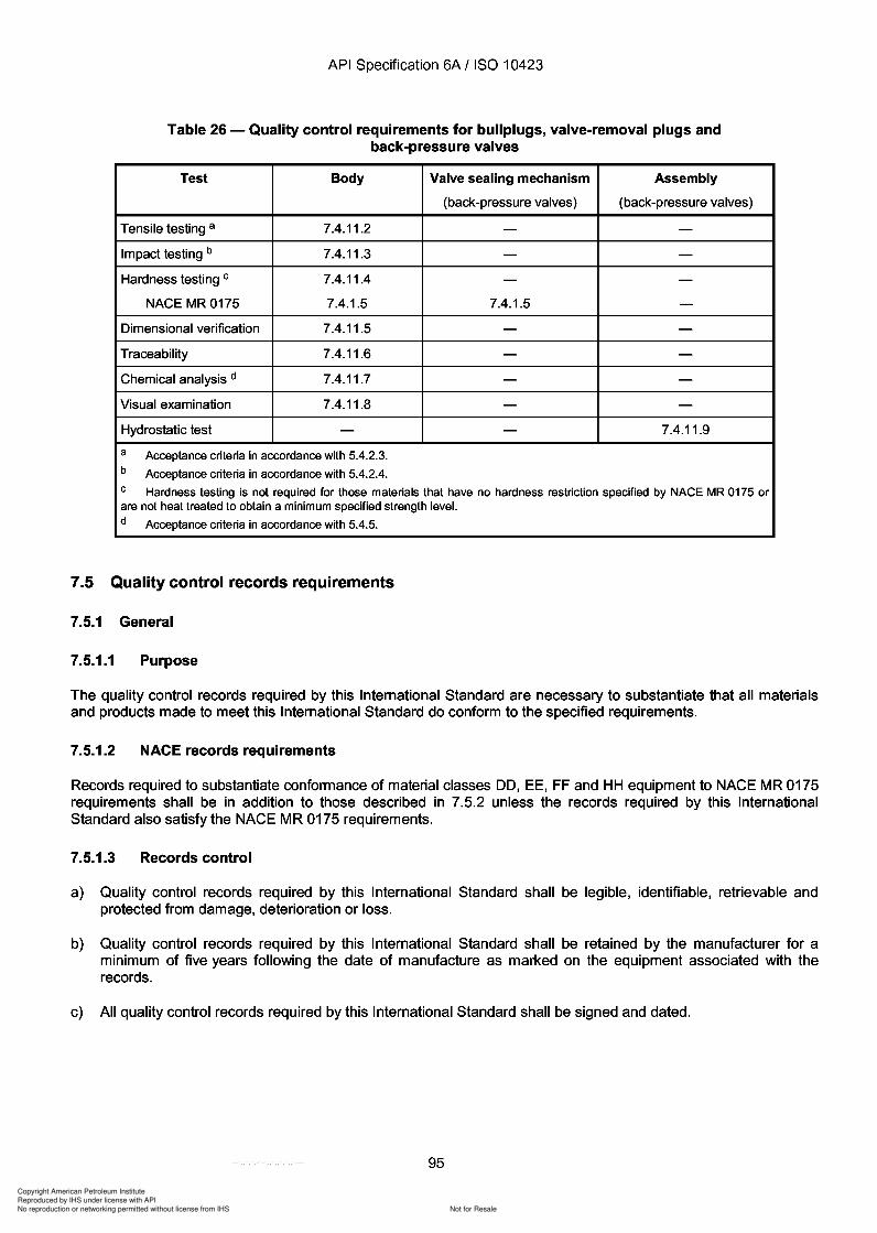
Copyright American Petroleum Institute
Reproduced by IHS under license with API
Not for ResaleNo reproduction or networking permitted without license from IHS
--`,,`,`,-`-`,,`,,`,`,,`---
API Specification 6A / ISO 10423
Table 26 - Quality control requirements for bullplugs, valve-removal plugs andback-pressure valves
Test Body Valve sealing mechanism Assembly
(back-pressure valves) (back-pressure valves)
Tensile testing a 7.4.11.2 - -Impact testing b 7.4.11.3 - -Hardness testing C 7.4.11.4 - -
NACE MR0175 7.4.1.5 7.4.1.5 -Dimensional verification 7.4.11.5 - -Traceability 7.4.11.6 - -Chemical analysis d 7.4.11.7 - -Visual examination 7.4.11.8 - -Hydrostatic test - - 7.4.11.9
a Acceptance criteria in accordance with 5.4.2.3.b Acceptance criteria in accordance with 5.4.2.4.C Hardness testing is not required for those materials that have no hardness restriction specified by NACE MR 0175 orare not heat treated to obtain a minimum specified strength level.d Acceptance criteria in accordance with 5.4.5.
7.5 Quality control records requirements
7.5.1 General
7.5.1.1 Purpose
The quality control records required by this International Standard are necessary to substantiate that all materialsand products made to meet this International Standard do conform to the specified requirements.
7.5.1.2 NACE records requirements
Records required to substantiate conformance of material classes DO, EE, FF and HH equipment to NACE MR 0175requirements shall be in addition to those described in 7.5.2 unless the records required by this InternationalStandard also satisfy the NACE MR 0175 requirements.
7.5.1.3 Records control
a) Quality control records required by this International Standard shall be legible, identifiable, retrievable andprotected from damage, deterioration or loss.
b) Quality control records required by this International Standard shall be retained by the manufacturer for aminimum of five years following the date of manufacture as marked on the equipment associated with therecords.
c) All quality control records required by this International Standard shall be signed and dated.
95
API Specification 6A / ISO 10423
Table 26 - Quality control requirements for bullplugs, valve-removal plugs and back-pressure valves
Test Body Valve sealing mechanism Assembly
(back-pressure valves) (back-pressure valves)
Tensile testing a 7.4.11.2 - -Impact testing b 7.4.11.3 - -Hardness testing C 7.4.11.4 - -
NACE MR0175 7.4.1.5 7.4.1.5 -Dimensional verification 7.4.11.5 - -Traceability 7.4.11.6 - -Chemical analysis d 7.4.11.7 - -Visual examination 7.4.11.8 - -Hydrostatic test - - 7.4.11.9
a Acceptance criteria in accordance with 5.4.2.3. b Acceptance criteria in accordance with 5.4.2.4. C Hardness testing is not required for those materials that have no hardness restriction specified by NACE MR 0175 or are not heat treated to obtain a minimum specified strength level. d Acceptance criteria in accordance with 5.4.5.
7.5 Quality control records requirements
7.5.1 General
7.5.1.1 Purpose
The quality control records required by this International Standard are necessary to substantiate that all materials and products made to meet this International Standard do conform to the specified requirements.
7.5.1.2 NACE records requirements
Records required to substantiate conformance of material classes DO, EE, FF and HH equipment to NACE MR 0175 requirements shall be in addition to those described in 7.5.2 unless the records required by this International Standard also satisfy the NACE MR 0175 requirements.
7.5.1.3 Records control
a) Quality control records required by this International Standard shall be legible, identifiable, retrievable and protected from damage, deterioration or loss.
b) Quality control records required by this International Standard shall be retained by the manufacturer for a minimum of five years following the date of manufacture as marked on the equipment associated with the records.
c) All quality control records required by this International Standard shall be signed and dated.
95
Copyright American Petroleum Institute
Reproduced by IHS under license with API
Not for ResaleNo reproduction or networking permitted without license from IHS
--`,,`,`,-`-`,,`,,`,`,,`---
Copyright American Petroleum Institute
Reproduced by IHS under license with API
Not for ResaleNo reproduction or networking permitted without license from IHS
--`,,`,`,-`-`,,`,,`,`,,`---
Copyright American Petroleum Institute
Reproduced by IHS under license with API
Not for ResaleNo reproduction or networking permitted without license from IHS
--`,,`,`,-`-`,,`,,`,`,,`---
API Specification 6A / ISO 10423
b) PSL 2
Assembled-equipment pressure test records:
actual test pressure;
holding period duration.
c) PSL 3
1) All records required for PSL 2 are also required for PSL 3.
2) Additionally, the following records are required:
assembly traceability records;
hydrostatic pressure test records.
3) Additionally, the following gas-test records are required for equipment designated PSL 3G:
actual test pressures;
actual holding period durations.
d) PSL 4
1) All records required for PSL 3 are also required for PSL 4.
2) Additionally, the following gas-test records are required:
actual test pressures;
actual holding period durations.
7.5.2.7 Choke trim records
a) PSL 1 and PSL 2
No records are required.
b) PSL 3 and PSL 4
Surface NDE records are required.
7.5.3 Records to be furnished to purchaser
7.5.3.1 General
These records shall be provided by the manufacturer to the original purchaser of equipment made to comply withthis International Standard.
These records, if applicable, shall be identical to or contain the same information as those retained by themanufacturer.
These records provided by the manufacturer shall prominently reference part serial number(s).
98
API Specification 6A / ISO 10423
b) PSL 2
Assembled-equipment pressure test records:
actual test pressure;
holding period duration.
c) PSL 3
1) All records required for PSL 2 are also required for PSL 3.
2) Additionally, the following records are required:
assembly traceability records;
hydrostatic pressure test records.
3) Additionally, the following gas-test records are required for equipment designated PSL 3G:
actual test pressures;
actual holding period durations.
d) PSL 4
1) All records required for PSL 3 are also required for PSL 4.
2) Additionally, the following gas-test records are required:
actual test pressures;
actual holding period durations.
7.5.2.7 Choke trim records
a) PSL 1 and PSL 2
No records are required.
b) PSL 3 and PSL 4
Surface NDE records are required.
7.5.3 Records to be furnished to purchaser
7.5.3.1 General
These records shall be provided by the manufacturer to the original purchaser of equipment made to comply with this International Standard.
These records, if applicable, shall be identical to or contain the same information as those retained by the manufacturer.
These records provided by the manufacturer shall prominently reference part serial number(s).
98
Copyright American Petroleum Institute
Reproduced by IHS under license with API
Not for ResaleNo reproduction or networking permitted without license from IHS
--`,,`,`,-`-`,,`,,`,`,,`---
API Specification 6A / ISO 10423
7.5.3.2 Body, bonnet, end and outlet connections, stem, valve-bore sealing mechanism, mandrel tubing-+ and casing hanger and back-pressure valve records
a) PSL 1 to PSL 3
No records are required.
b) PSL 4
The following records are required:
NDE records;
hardness test records;
material test records;
heat treatment records.
7.5.3.3 Ring gasket records
No records are required.
7.5.3.4 Studs and nuts records
No records are required.
7.5.3.5 Non-metallic sealing material records
a) PSL 1 to PSL 3
No records are required.
b) PSL 4
Certification of compliance stating that non-metallic seals conform to PSL 4 of this International Standard.
7.5.3.6 Assembled equipment records
a) PSL 1 and PSL 2
No records are required.
b) PSL 3
The following records are required:
certificate of compliance stating that equipment conforms to PSL 3 of this International Standard, and thetemperature and material class;
assembly traceability records;
pressure test records.
c) PSL 3G and PSL 4
All records/certifications of PSL 3 are also required for PSL 3G and PSL 4. Additionally, gas-test records shallbe furnished.
99
API Specification 6A / ISO 10423
7.5.3.2 Body, bonnet, end and outlet connections, stem, valve-bore sealing mechanism, mandrel tubing -+ and casing hanger and back-pressure valve records
a) PSL 1 to PSL 3
No records are required.
b) PSL 4
The following records are required:
NDE records;
hardness test records;
material test records;
heat treatment records.
7.5.3.3 Ring gasket records
No records are required.
7.5.3.4 Studs and nuts records
No records are required.
7.5.3.5 Non-metallic sealing material records
a) PSL 1 to PSL 3
No records are required.
b) PSL 4
Certification of compliance stating that non-metallic seals conform to PSL 4 of this International Standard.
7.5.3.6 Assembled equipment records
a) PSL 1 and PSL 2
No records are required.
b) PSL 3
The following records are required:
certificate of compliance stating that equipment conforms to PSL 3 of this International Standard, and the temperature and material class;
assembly traceability records;
pressure test records.
c) PSL 3G and PSL 4
All records/certifications of PSL 3 are also required for PSL 3G and PSL 4. Additionally, gas-test records shall be furnished.
99
Copyright American Petroleum Institute
Reproduced by IHS under license with API
Not for ResaleNo reproduction or networking permitted without license from IHS
--`,,`,`,-`-`,,`,,`,`,,`---
API Specification 6A / ISO 10423
8 Equipment marking
8.1 Marking requirements
8.1.1 General
Equipment shall be marked on the exterior surface as specified in Table 27. Marking shall contain the designationISO 10423, the temperature rating, material class, product specification level, performance requirement level, dateof manufacture (month and year), and manufacturer's name or mark. Other marking shall be as specified inTables 27, 28, 29, 30, 31, 32, 33 and 34. Marking for features that do not exist on a product is not applicable.
-+8.1.2 Marking method
Marking using low-stress (dot, vibration or rounded V) stamps is acceptable. Conventional sharp V-stamping isacceptable in low-stress areas, such as the outside diameter of flanges. Sharp V-stamping is not permitted in highstress areas unless subsequently stress-relieved at 590°C (1 100 OF) minimum. The method of marking onnameplates is optional.
8.1.3 Nameplates
Nameplates are not required if the information is permanently marked on the body or connector.
8.1.4 Hidden marking
Marking required on a connector 00 that would be covered by clamps or other parts of the connector assemblyshall be stamped in a visible location near the connector.
8.1.5 Thread marking
The thread type marking, in accordance with ISO 11960, shall be as follows:
line pipe: LP;
casing (short thread): STC;
casing (long thread): LC;
casing (buttress): BC;
casing (extreme line): XL;
tubing (non-upset): NU;
tubing (external-upset): EU.
8.1.6 Size marking
The marking of size shall include the nominal size and, if applicable, the restricted or over-size bore.
8.1.7 Weld metal overlay
If equipment has metal overlaid corrosion-resistant ring grooves, the ring gasket type and number shall be followedby "CRA" to designate a corrosion-resistant alloy, or "SST" to designate an austenitic stainless steel.
100
-+
API Specification 6A / ISO 10423
8 Equipment marking
8.1 Marking requirements
8.1.1 General
Equipment shall be marked on the exterior surface as specified in Table 27. Marking shall contain the designation ISO 10423, the temperature rating, material class, product specification level, performance requirement level, date of manufacture (month and year), and manufacturer's name or mark. Other marking shall be as specified in Tables 27, 28, 29, 30, 31, 32, 33 and 34. Marking for features that do not exist on a product is not applicable.
8.1.2 Marking method
Marking using low-stress (dot, vibration or rounded V) stamps is acceptable. Conventional sharp V-stamping is acceptable in low-stress areas, such as the outside diameter of flanges. Sharp V-stamping is not permitted in highstress areas unless subsequently stress-relieved at 590°C (1 100 OF) minimum. The method of marking on nameplates is optional.
8.1.3 Nameplates
Nameplates are not required if the information is permanently marked on the body or connector.
8.1.4 Hidden marking
Marking required on a connector 00 that would be covered by clamps or other parts of the connector assembly shall be stamped in a visible location near the connector.
8.1.5 Thread marking
The thread type marking, in accordance with ISO 11960, shall be as follows:
line pipe: LP;
casing (short thread): STC;
casing (long thread): LC;
casing (buttress): BC;
casing (extreme line): XL;
tubing (non-upset): NU;
tubing (external-upset): EU.
8.1.6 Size marking
The marking of size shall include the nominal size and, if applicable, the restricted or over-size bore.
8.1.7 Weld metal overlay
If equipment has metal overlaid corrosion-resistant ring grooves, the ring gasket type and number shall be followed by "CRA" to designate a corrosion-resistant alloy, or "SST" to designate an austenitic stainless steel.
100
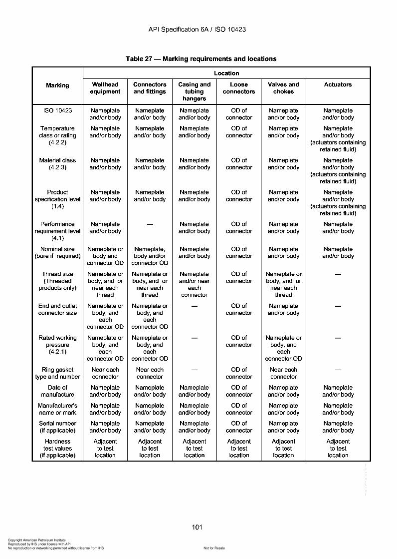
Copyright American Petroleum Institute
Reproduced by IHS under license with API
Not for ResaleNo reproduction or networking permitted without license from IHS
--`,,`,`,-`-`,,`,,`,`,,`---
API Specification 6A / ISO 10423
Table 27 - Marking requirements and locations
Location
Marking Wellhead Connectors Casing and Loose Valves and Actuatorsequipment and fittings tubing connectors chokes
hangers
ISO 10423 Nameplate Nameplate Nameplate 00 of Nameplate Nameplateand/or body and/or body and/or body connector and/or body and/or body
Temperature Nameplate Nameplate Nameplate 00 of Nameplate Nameplateclass or rating and/or body and/or body and/or body connector and/or body and/or body
(4.2.2) (actuators containingretained fluid)
Material class Nameplate Nameplate Nameplate 00 of Nameplate Nameplate(4.2.3) and/or body and/or body and/or body connector and/or body and/or body
(actuators containingretained fluid)
Product Nameplate Nameplate Nameplate 00 of Nameplate Nameplatespecification level and/or body and/or body and/or body connector and/or body and/or body
(1.4) (actuators containingretained fluid)
Performance Nameplate - Nameplate 00 of Nameplate Nameplaterequirement level and/or body and/or body connector and/or body and/or body
(4.1 )
Nominal size Nameplate or Nameplate, Nameplate 00 of Nameplate Nameplate(bore if required) body and body and/or and/or body connector and/or body and/or body
connector 00 connector 00
Thread size Nameplate or Nameplate or Nameplate 00 of Nameplate or -(Threaded body, and or body, and or and/or near connector body, and or
products only) near each near each each near eachthread thread connector thread
End and outlet Nameplate or Nameplate or - 00 of Nameplate -connector size bodY,and bodY,and connector and/or body
each eachconnector 00 connector 00
Rated working Nameplate or Nameplate or - 00 of Nameplate or -pressure bodY,and bodY,and connector bodY,and(4.2.1 ) each each each
connector 00 connector 00 connector 00
Ring gasket Near each Near each - 00 of Near each -type and number connector connector connector connector
Oate of Nameplate Nameplate Nameplate 00 of Nameplate Nameplatemanufacture and/or body and/or body and/or body connector and/or body and/or body
Manufacturer's Nameplate Nameplate Nameplate 00 of Nameplate Nameplatename or mark and/or body and/or body and/or body connector and/or body and/or body
Serial number Nameplate Nameplate Nameplate 00 of Nameplate Nameplate(if applicable) and/or body and/or body and/or body connector and/or body and/or body
Hardness Adjacent Adjacent Adjacent Adjacent Adjacent Adjacenttest values to test to test to test to test to test to test
(if applicable) location location location location location location
101
API Specification 6A / ISO 10423
Table 27 - Marking requirements and locations
Location
Marking Wellhead Connectors Casing and Loose Valves and Actuators equipment and fittings tubing connectors chokes
hangers
ISO 10423 Nameplate Nameplate Nameplate 00 of Nameplate Nameplate and/or body and/or body and/or body connector and/or body and/or body
Temperature Nameplate Nameplate Nameplate 00 of Nameplate Nameplate class or rating and/or body and/or body and/or body connector and/or body and/or body
(4.2.2) (actuators containing retained fluid)
Material class Nameplate Nameplate Nameplate 00 of Nameplate Nameplate (4.2.3) and/or body and/or body and/or body connector and/or body and/or body
(actuators containing retained fluid)
Product Nameplate Nameplate Nameplate 00 of Nameplate Nameplate specification level and/or body and/or body and/or body connector and/or body and/or body
(1.4) (actuators containing retained fluid)
Performance Nameplate - Nameplate 00 of Nameplate Nameplate requirement level and/or body and/or body connector and/or body and/or body
(4.1 )
Nominal size Nameplate or Nameplate, Nameplate 00 of Nameplate Nameplate (bore if required) body and body and/or and/or body connector and/or body and/or body
connector 00 connector 00
Thread size Nameplate or Nameplate or Nameplate 00 of Nameplate or -(Threaded body, and or body, and or and/or near connector body, and or
products only) near each near each each near each thread thread connector thread
End and outlet Nameplate or Nameplate or - 00 of Nameplate -connector size bodY,and bodY,and connector and/or body
each each connector 00 connector 00
Rated working Nameplate or Nameplate or - 00 of Nameplate or -pressure bodY,and bodY,and connector bodY,and (4.2.1 ) each each each
connector 00 connector 00 connector 00
Ring gasket Near each Near each - 00 of Near each -type and number connector connector connector connector
Oate of Nameplate Nameplate Nameplate 00 of Nameplate Nameplate manufacture and/or body and/or body and/or body connector and/or body and/or body
Manufacturer's Nameplate Nameplate Nameplate 00 of Nameplate Nameplate name or mark and/or body and/or body and/or body connector and/or body and/or body
Serial number Nameplate Nameplate Nameplate 00 of Nameplate Nameplate (if applicable) and/or body and/or body and/or body connector and/or body and/or body
Hardness Adjacent Adjacent Adjacent Adjacent Adjacent Adjacent test values to test to test to test to test to test to test
(if applicable) location location location location location location
101

Copyright American Petroleum Institute
Reproduced by IHS under license with API
Not for ResaleNo reproduction or networking permitted without license from IHS
--`,,`,`,-`-`,,`,,`,`,,`---
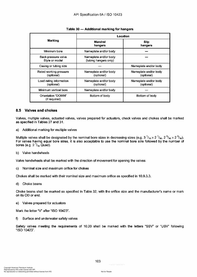
Copyright American Petroleum Institute
Reproduced by IHS under license with API
Not for ResaleNo reproduction or networking permitted without license from IHS
--`,,`,`,-`-`,,`,,`,`,,`---
API Specification 6A / ISO 10423
Table 30 - Additional marking for hangers
Location
Marking Mandrel Sliphangers hangers
Minimum bore Nameplate and/or body -Back-pressure valve Nameplate and/or body -
Style or model (tubing hangers only)
Casing or tubing size - Nameplate and/or body
Rated working pressure Nameplate and/or body Nameplate and/or body(optional) (optional) (optional)
Load rating information Nameplate and/or body Nameplate and/or body(optional) (optional) (optional)
Minimum vertical bore Nameplate and/or body -Orientation "DOWN" Bottom of body Bottom of body
(if required)
8.5 Valves and chokes
Valves, multiple valves, actuated valves, valves prepared for actuators, check valves and chokes shall be markedas specified in Tables 27 and 31.
a) Additional marking for multiple valves
Multiple valves shall be designated by the nominal bore sizes in decreasing sizes (e.g. 3 1/16 X 2 1/16, 2 9/ 16 X 2 9/16).
For valves having equal bore sizes, it is also acceptable to use the nominal bore size followed by the number ofbores (e.g. 2 1
/ 16 Quad).
b) Valve handwheels
Valve handwheels shall be marked with the direction of movement for opening the valves.
c) Nominal size and maximum orifice for chokes
Chokes shall be marked with their nominal size and maximum orifice as specified in 10.9.3.3.
d) Choke beans
Choke beans shall be marked as specified in Table 32, with the orifice size and the manufacturer's name or markon its 00 or end.
e) Valves prepared for actuators
Mark the letter "V' after "ISO 10423".
f) Surface and underwater safety valves
Safety valves meeting the requirements of 10.20 shall be marked with the letters "SSV' or "USV" following"ISO 10423".
103
API Specification 6A / ISO 10423
Table 30 - Additional marking for hangers
Location
Marking Mandrel Slip hangers hangers
Minimum bore Nameplate and/or body -Back-pressure valve Nameplate and/or body -
Style or model (tubing hangers only)
Casing or tubing size - Nameplate and/or body
Rated working pressure Nameplate and/or body Nameplate and/or body (optional) (optional) (optional)
Load rating information Nameplate and/or body Nameplate and/or body (optional) (optional) (optional)
Minimum vertical bore Nameplate and/or body -Orientation "DOWN" Bottom of body Bottom of body
(if required)
8.5 Valves and chokes
Valves, multiple valves, actuated valves, valves prepared for actuators, check valves and chokes shall be marked as specified in Tables 27 and 31.
a) Additional marking for multiple valves
Multiple valves shall be designated by the nominal bore sizes in decreasing sizes (e.g. 3 1/16 X 2 1/16, 2 9/ 16 X 2 9/16).
For valves having equal bore sizes, it is also acceptable to use the nominal bore size followed by the number of bores (e.g. 2 1
/ 16 Quad).
b) Valve handwheels
Valve handwheels shall be marked with the direction of movement for opening the valves.
c) Nominal size and maximum orifice for chokes
Chokes shall be marked with their nominal size and maximum orifice as specified in 10.9.3.3.
d) Choke beans
Choke beans shall be marked as specified in Table 32, with the orifice size and the manufacturer's name or mark on its 00 or end.
e) Valves prepared for actuators
Mark the letter "V' after "ISO 10423".
f) Surface and underwater safety valves
Safety valves meeting the requirements of 1 0.20 shall be marked with the letters "SSV' or "USV" following "ISO 10423".
103
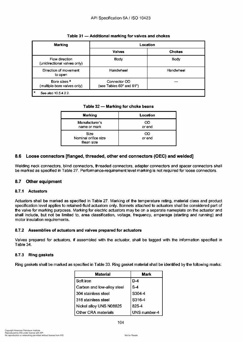
Copyright American Petroleum Institute
Reproduced by IHS under license with API
Not for ResaleNo reproduction or networking permitted without license from IHS
--`,,`,`,-`-`,,`,,`,`,,`---
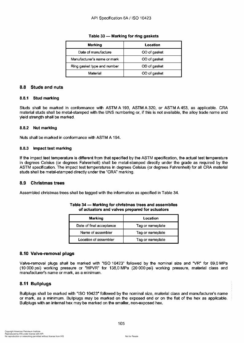
Copyright American Petroleum Institute
Reproduced by IHS under license with API
Not for ResaleNo reproduction or networking permitted without license from IHS
--`,,`,`,-`-`,,`,,`,`,,`---
API Specification 6A / ISO 10423
Table 33 - Marking for ring gaskets
Marking Location
Date of manufacture 00 of gasket
Manufacturer's name or mark 00 of gasket
Ring gasket type and number 00 of gasket
Material 00 of gasket
8.8 Studs and nuts
8.8.1 Stud marking
Studs shall be marked in conformance with ASTM A 193, ASTM A 320, or ASTM A 453, as applicable. CRAmaterial studs shall be metal-stamped with the UNS numbering or, if this is not available, the alloy trade name andyield strength shall be marked.
8.8.2 Nut marking
Nuts shall be marked in conformance with ASTM A 194.
8.8.3 Impact test marking
If the impact test temperature is different from that specified by the ASTM specification, the actual test temperaturein degrees Celsius (or degrees Fahrenheit) shall be metal-stamped directly under the grade as required by theASTM specification. The impact test temperatures in degrees Celsius (or degrees Fahrenheit) for all CRA materialstuds shall be metal-stamped directly under the "CRA" marking.
8.9 Christmas trees
Assembled christmas trees shall be tagged with the information as specified in Table 34.
Table 34 - Marking for christmas trees and assembliesof actuators and valves prepared for actuators
Marking Location
Date of final acceptance Tag or nameplate
Name of assembler Tag or nameplate
Location of assembler Tag or nameplate
8.10 Valve-removal plugs
Valve-removal plugs shall be marked with "ISO 10423" followed by the nominal size and "VR" for 69,0 MPa(10000 psi) working pressure or "HPVR" for 138,0 MPa (20000 psi) working pressure, material class andmanufacturer's name or mark, as a minimum.
8.11 Bullplugs
Bullplugs shall be marked with "ISO 10423" followed by the nominal size, material class and manufacturer's nameor mark, as a minimum. Bullplugs may be marked on the exposed end or on the flat of the hex as applicable.Bullplugs with an internal hex may be marked on the smaller, non-exposed hex.
105
API Specification 6A / ISO 10423
Table 33 - Marking for ring gaskets
Marking Location
Date of manufacture 00 of gasket
Manufacturer's name or mark 00 of gasket
Ring gasket type and number 00 of gasket
Material 00 of gasket
8.8 Studs and nuts
8.8.1 Stud marking
Studs shall be marked in conformance with ASTM A 193, ASTM A 320, or ASTM A 453, as applicable. CRA material studs shall be metal-stamped with the UNS numbering or, if this is not available, the alloy trade name and yield strength shall be marked.
8.8.2 Nut marking
Nuts shall be marked in conformance with ASTM A 194.
8.8.3 Impact test marking
If the impact test temperature is different from that specified by the ASTM specification, the actual test temperature in degrees Celsius (or degrees Fahrenheit) shall be metal-stamped directly under the grade as required by the ASTM specification. The impact test temperatures in degrees Celsius (or degrees Fahrenheit) for all CRA material studs shall be metal-stamped directly under the "CRA" marking.
8.9 Christmas trees
Assembled christmas trees shall be tagged with the information as specified in Table 34.
Table 34 - Marking for christmas trees and assemblies of actuators and valves prepared for actuators
Marking Location
Date of final acceptance Tag or nameplate
Name of assembler Tag or nameplate
Location of assembler Tag or nameplate
8.10 Valve-removal plugs
Valve-removal plugs shall be marked with "ISO 1 0423" followed by the nominal size and "VR" for 69,0 MPa (10000 psi) working pressure or "HPVR" for 138,0 MPa (20000 psi) working pressure, material class and manufacturer's name or mark, as a minimum.
8.11 Bullplugs
Bullplugs shall be marked with "ISO 10423" followed by the nominal size, material class and manufacturer's name or mark, as a minimum. Bullplugs may be marked on the exposed end or on the flat of the hex as applicable. Bullplugs with an internal hex may be marked on the smaller, non-exposed hex.
105
Copyright American Petroleum Institute
Reproduced by IHS under license with API
Not for ResaleNo reproduction or networking permitted without license from IHS
--`,,`,`,-`-`,,`,,`,`,,`---
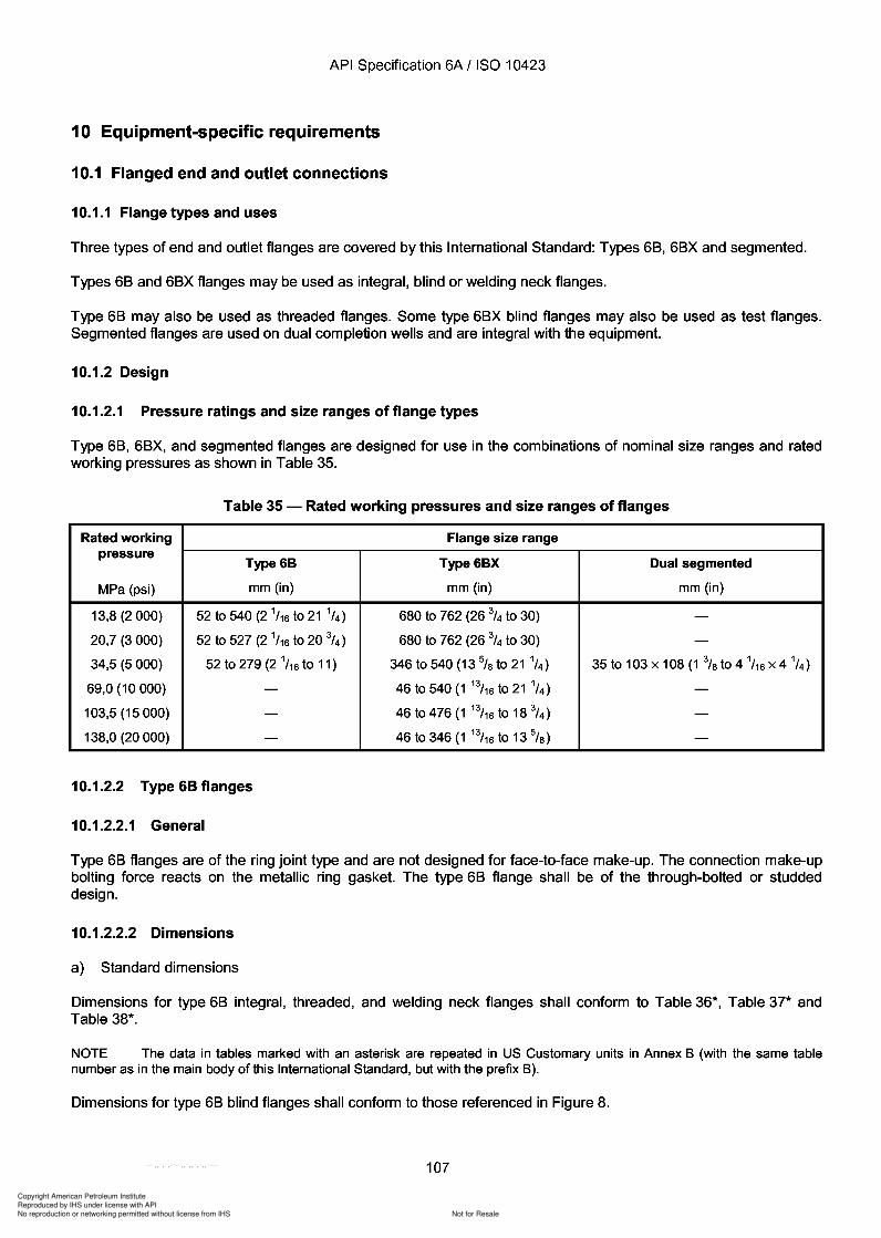
Copyright American Petroleum Institute
Reproduced by IHS under license with API
Not for ResaleNo reproduction or networking permitted without license from IHS
--`,,`,`,-`-`,,`,,`,`,,`---
API Specification 6A / ISO 10423
10 Equipment-specific requirements
10.1 Flanged end and outlet connections
10.1.1 Flange types and uses
Three types of end and outlet flanges are covered by this International Standard: Types 68, 68X and segmented.
Types 68 and 68X flanges may be used as integral, blind or welding neck flanges.
Type 68 may also be used as threaded flanges. Some type 68X blind flanges may also be used as test flanges.Segmented flanges are used on dual completion wells and are integral with the equipment.
10.1.2 Design
10.1.2.1 Pressure ratings and size ranges of flange types
Type 68, 68X, and segmented flanges are designed for use in the combinations of nominal size ranges and ratedworking pressures as shown in Table 35.
Table 35 - Rated working pressures and size ranges of flanges
Rated working Flange size rangepressure
Type6B Type6BX Dual segmented
MPa (psi) mm (in) mm (in) mm (in)
13,8 (2 000) 52 to 540 (2 1/16 to 21 1/4 ) 680 to 762 (26 3/4 to 30) -20,7 (3000) 52 to 527 (2 1/16 to 20 3/4 ) 680 to 762 (26 3/4 to 30) -34,5 (5000) 52 to 279 (2 1/16 to 11) 346 to 540 (13 %to 21 1
/4) 35 to 103 x 108 (1 %to 4 1/16 X 4 1/4 )
69,0 (10 000) - 46 to 540 (1 13/16 to 21 1/4 ) -103,5 (15000) - 46 to 476 (1 13/16 to 18 3
/ 4 ) -138,0 (20000) - 46 to 346 (1 13
/16 to 13 %) -
10.1.2.2 Type 68 flanges
10.1.2.2.1 General
Type 68 flanges are of the ring joint type and are not designed for face-to-face make-up. The connection make-upbolting force reacts on the metallic ring gasket. The type 68 flange shall be of the through-bolted or studdeddesign.
10.1.2.2.2 Dimensions
a) Standard dimensions
Dimensions for type 68 integral, threaded, and welding neck flanges shall conform to Table 36*, Table 37* andTable 38*.
NOTE The data in tables marked with an asterisk are repeated in US Customary units in Annex B (with the same tablenumber as in the main body of this International Standard, but with the prefix B).
Dimensions for type 68 blind flanges shall conform to those referenced in Figure 8.
107
API Specification 6A / ISO 10423
10 Equipment-specific requirements
10.1 Flanged end and outlet connections
10.1.1 Flange types and uses
Three types of end and outlet flanges are covered by this International Standard: Types 68, 68X and segmented.
Types 68 and 68X flanges may be used as integral, blind or welding neck flanges.
Type 68 may also be used as threaded flanges. Some type 68X blind flanges may also be used as test flanges. Segmented flanges are used on dual completion wells and are integral with the equipment.
10.1.2 Design
10.1.2.1 Pressure ratings and size ranges of flange types
Type 68, 68X, and segmented flanges are designed for use in the combinations of nominal size ranges and rated working pressures as shown in Table 35.
Table 35 - Rated working pressures and size ranges of flanges
Rated working Flange size range pressure
Type 68 Type68X Dual segmented
MPa (psi) mm (in) mm (in) mm (in)
13,8 (2 000) 52 to 540 (2 1/16 to 21 1/4) 680 to 762 (26 3/4 to 30) -20,7 (3000) 52 to 527 (2 1/16 to 20 3/4) 680 to 762 (26 3/4 to 30) -34,5 (5000) 52 to 279 (2 1/16 to 11) 346 to 540 (13 % to 211/4) 35 to 103 x 108 (1 % to 4 1/16 X 4 1/4)
69,0 (10 000) - 46 to 540 (1 13/16 to 21 1/4) -103,5 (15000) - 46 to 476 (1 13/16 to 18 3/4) -138,0 (20000) - 46 to 346 (1 13/16 to 13 %) -
10.1.2.2 Type 68 flanges
10.1.2.2.1 General
Type 68 flanges are of the ring joint type and are not designed for face-to-face make-up. The connection make-up bolting force reacts on the metallic ring gasket. The type 68 flange shall be of the through-bolted or studded design.
10.1.2.2.2 Dimensions
a) Standard dimensions
Dimensions for type 68 integral, threaded, and welding neck flanges shall conform to Table 36*, Table 37* and Table 38*.
NOTE The data in tables marked with an asterisk are repeated in US Customary units in Annex B (with the same table number as in the main body of this International Standard, but with the prefix B).
Dimensions for type 68 blind flanges shall conform to those referenced in Figure 8.
107
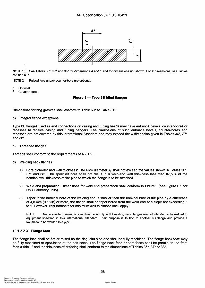
Copyright American Petroleum Institute
Reproduced by IHS under license with API
Not for ResaleNo reproduction or networking permitted without license from IHS
--`,,`,`,-`-`,,`,,`,`,,`---
Copyright American Petroleum Institute
Reproduced by IHS under license with API
Not for ResaleNo reproduction or networking permitted without license from IHS
--`,,`,`,-`-`,,`,,`,`,,`---
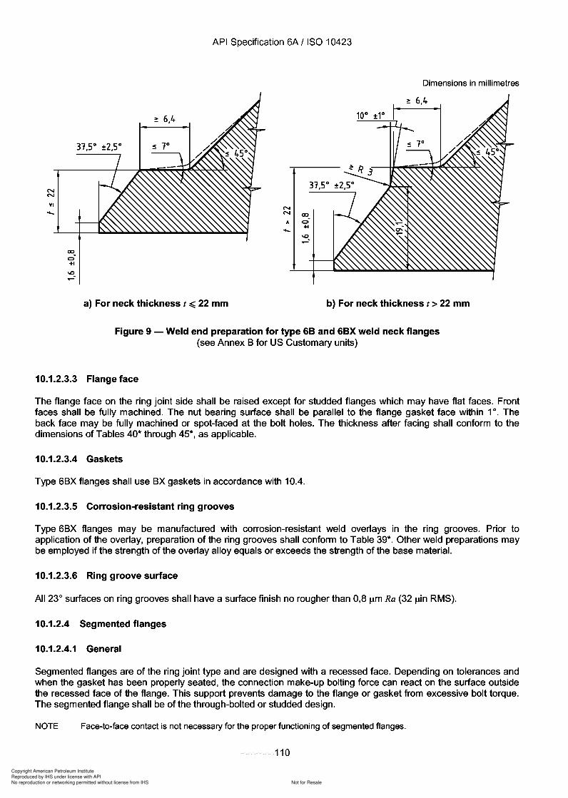
2 6.4
Copyright American Petroleum Institute
Reproduced by IHS under license with API
Not for ResaleNo reproduction or networking permitted without license from IHS
--`,,`,`,-`-`,,`,,`,`,,`---
API Specification 6A / ISO 10423
Dimensions in millimetres
NN
VI
lXJ
C>+1
-.0
31,5°
NN lXJ
A C>+1.....
-.0~
a) For neck thickness t ~ 22 mm b) For neck thickness t> 22 mm
Figure 9 - Weld end preparation for type 68 and 68X weld neck flanges(see Annex B for US Customary units)
10.1.2.3.3 Flange face
The flange face on the ring joint side shall be raised except for studded flanges which may have flat faces. Frontfaces shall be fully machined. The nut bearing surface shall be parallel to the flange gasket face within 10. Theback face may be fully machined or spot-faced at the bolt holes. The thickness after facing shall conform to thedimensions of Tables 40* through 45*, as applicable.
10.1.2.3.4 Gaskets
Type 6BX flanges shall use BX gaskets in accordance with 10.4.
10.1.2.3.5 Corrosion-resistant ring grooves
Type 6BX flanges may be manufactured with corrosion-resistant weld overlays in the ring grooves. Prior toapplication of the overlay, preparation of the ring grooves shall conform to Table 39*. Other weld preparations maybe employed if the strength of the overlay alloy equals or exceeds the strength of the base material.
10.1.2.3.6 Ring groove surface
All 23° surfaces on ring grooves shall have a surface finish no rougher than 0,8 /lm Ra (32 /lin RMS).
10.1.2.4 Segmented flanges
10.1.2.4.1 General
Segmented flanges are of the ring joint type and are designed with a recessed face. Depending on tolerances andwhen the gasket has been properly seated, the connection make-up bolting force can react on the surface outsidethe recessed face of the flange. This support prevents damage to the flange or gasket from excessive bolt torque.The segmented flange shall be of the through-bolted or studded design.
NOTE Face-to-face contact is not necessary for the proper functioning of segmented flanges.
110
N N
VI
CXJ
C> +1
-.0
API Specification 6A / ISO 10423
Dimensions in millimetres
31,5°
N N CXJ
A C> +1 .....
-.0 ~
a) For neck thickness t ~ 22 mm b) For neck thickness t> 22 mm
Figure 9 - Weld end preparation for type 68 and 68X weld neck flanges (see Annex B for US Customary units)
10.1.2.3.3 Flange face
The flange face on the ring joint side shall be raised except for studded flanges which may have flat faces. Front faces shall be fully machined. The nut bearing surface shall be parallel to the flange gasket face within 10. The back face may be fully machined or spot-faced at the bolt holes. The thickness after facing shall conform to the dimensions of Tables 40* through 45*, as applicable.
10.1.2.3.4 Gaskets
Type 6BX flanges shall use BX gaskets in accordance with 10.4.
10.1.2.3.5 Corrosion-resistant ring grooves
Type 6BX flanges may be manufactured with corrosion-resistant weld overlays in the ring grooves. Prior to application of the overlay, preparation of the ring grooves shall conform to Table 39*. Other weld preparations may be employed if the strength of the overlay alloy equals or exceeds the strength of the base material.
10.1.2.3.6 Ring groove surface
All 23 0 surfaces on ring grooves shall have a surface finish no rougher than 0,8 /lm Ra (32 /lin RMS).
10.1.2.4 Segmented flanges
10.1.2.4.1 General
Segmented flanges are of the ring joint type and are designed with a recessed face. Depending on tolerances and when the gasket has been properly seated, the connection make-up bolting force can react on the surface outside the recessed face of the flange. This support prevents damage to the flange or gasket from excessive bolt torque. The segmented flange shall be of the through-bolted or studded design.
NOTE Face-to-face contact is not necessary for the proper functioning of segmented flanges.
110
Copyright American Petroleum Institute
Reproduced by IHS under license with API
Not for ResaleNo reproduction or networking permitted without license from IHS
--`,,`,`,-`-`,,`,,`,`,,`---
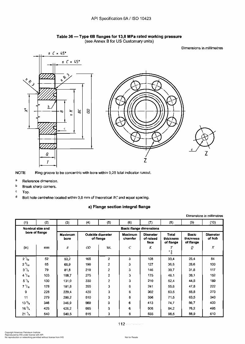
Copyright American Petroleum Institute
Reproduced by IHS under license with API
Not for ResaleNo reproduction or networking permitted without license from IHS
--`,,`,`,-`-`,,`,,`,`,,`---
API Specification 6A / ISO 10423
Table 36 - Type 68 flanges for 13,8 MPa rated working pressure(see Annex B for US Customary units)
Dimensions in millimetres
aT
1\1
zNOTE Ring groove to be concentric with bore within 0,25 total indicator runout.
a
b
c
d
Reference dimension.
Break sharp corners.
Top.
Bolt hole centreline located within 0,8 mm of theoretical Be and equal spacing.
a) Flange section integral flange
Dimensions in millimetres
(1 ) (2) (3) (4) (5) (6) (7) (8) (9) (10)
Nominal size and Basic flange dimensionsbore of flange
Maximum Outside diameter Maximum Diameter Total Basic Diameterbore of flange chamfer of raised thickness thickness of hub
face of flange of flange
(in) mm B OD tol. e K T Q X+3
0
2 1/ 16 52 53,2 165 2 3 108 33,4 25,4 84
2 9/ 16 65 65,9 190 2 3 127 36,6 28,6 100
3 1/S 79 81,8 210 2 3 146 39,7 31,8 117
4 1/ 16 103 108,7 275 2 3 175 46,1 38,1 152
5 1/s 130 131,0 330 2 3 210 52,4 44,5 189
7 1/ 16 178 181,8 355 3 6 241 55,6 47,6 222
9 228 229,4 420 3 6 302 63,5 55,6 273
11 279 280,2 510 3 6 356 71,5 63,5 343
13% 346 346,9 560 3 6 413 74,7 66,7 400
16 3/ 4 425 426,2 685 3 6 508 84,2 76,2 495
21 1/4 540 540,5 815 3 6 635 98,5 88,9 610
112
a T
API Specification 6A / ISO 10423
Table 36 - Type 68 flanges for 13,8 MPa rated working pressure (see Annex B for US Customary units)
z NOTE Ring groove to be concentric with bore within 0,25 total indicator runout.
a
b
c
d
Reference dimension.
Break sharp corners.
Top.
Bolt hole centreline located within 0,8 mm of theoretical Be and equal spacing.
a) Flange section integral flange
(1 ) (2) (3) (4) (5) (6) (7)
Nominal size and Basic flange dimensions bore of flange
Maximum Outside diameter Maximum Diameter bore of flange chamfer of raised
face
(in) mm B OD tol. C K
2 1/ 16 52 53,2 165 2 3 108
2 9/ 16 65 65,9 190 2 3 127
3 1/8 79 81,8 210 2 3 146
4 1/ 16 103 108,7 275 2 3 175
5 1/8 130 131,0 330 2 3 210
7 1/ 16 178 181,8 355 3 6 241
9 228 229,4 420 3 6 302
11 279 280,2 510 3 6 356
13% 346 346,9 560 3 6 413
16 3/ 4 425 426,2 685 3 6 508
21 1/4 540 540,5 815 3 6 635
112
(8)
Total thickness of flange
T +3
0
33,4
36,6
39,7
46,1
52,4
55,6
63,5
71,5
74,7
84,2
98,5
Dimensions in millimetres
Dimensions in millimetres
(9) (10)
Basic Diameter thickness of hub of flange
Q X
25,4 84
28,6 100
31,8 117
38,1 152
44,5 189
47,6 222
55,6 273
63,5 343
66,7 400
76,2 495
88,9 610
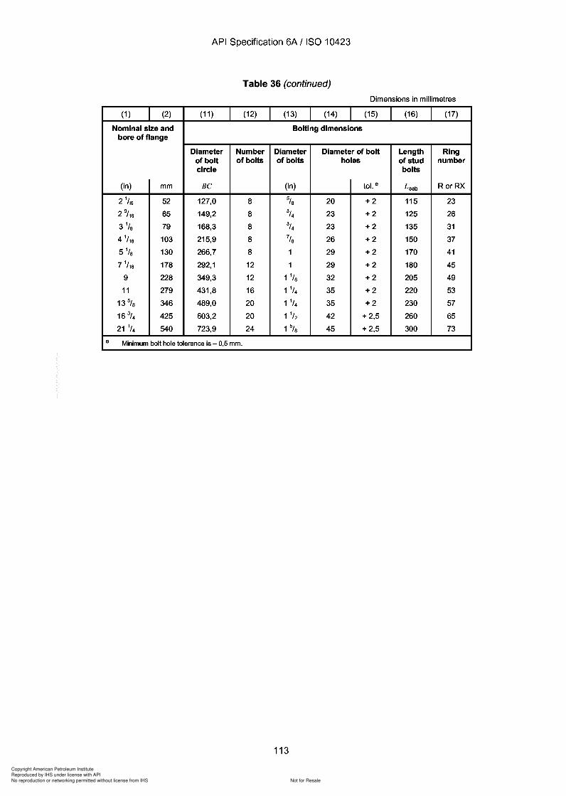
Copyright American Petroleum Institute
Reproduced by IHS under license with API
Not for ResaleNo reproduction or networking permitted without license from IHS
--`,,`,`,-`-`,,`,,`,`,,`---
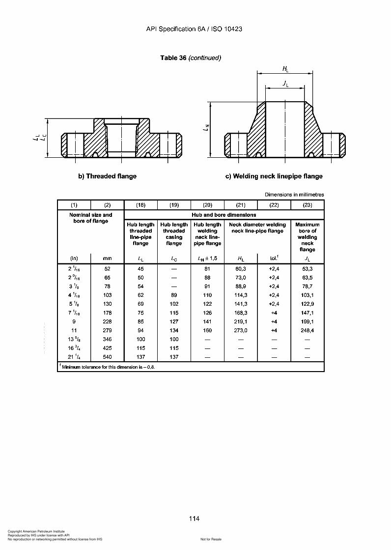
Copyright American Petroleum Institute
Reproduced by IHS under license with API
Not for ResaleNo reproduction or networking permitted without license from IHS
--`,,`,`,-`-`,,`,,`,`,,`---
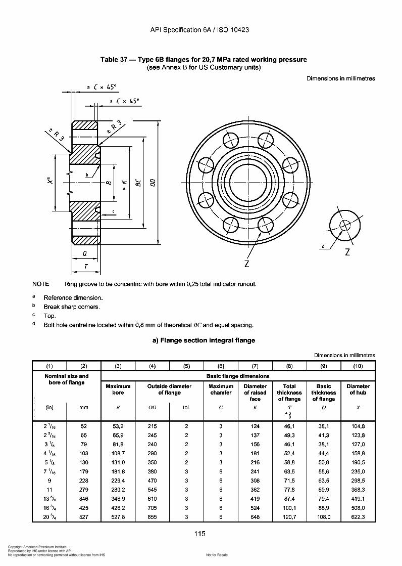
Copyright American Petroleum Institute
Reproduced by IHS under license with API
Not for ResaleNo reproduction or networking permitted without license from IHS
--`,,`,`,-`-`,,`,,`,`,,`---
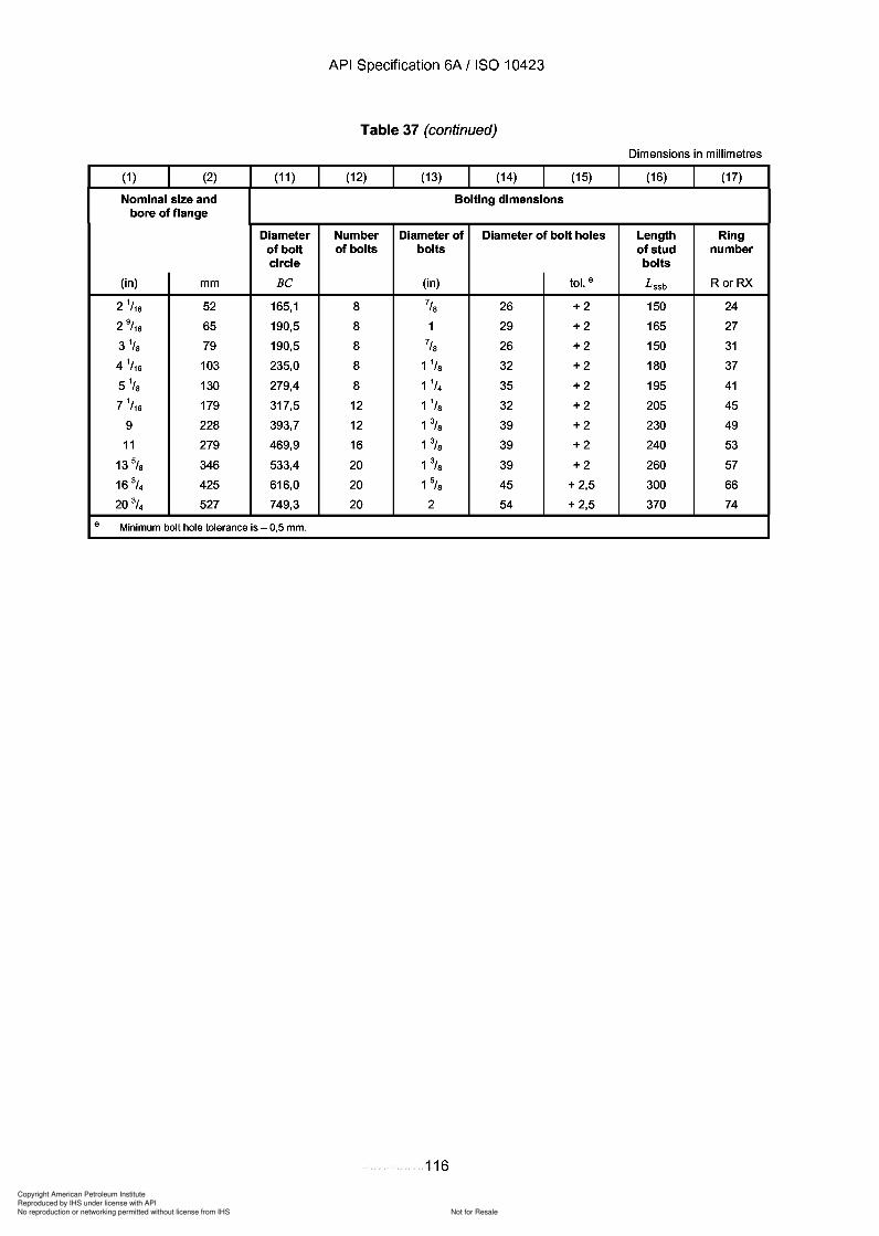
Copyright American Petroleum Institute
Reproduced by IHS under license with API
Not for ResaleNo reproduction or networking permitted without license from IHS
--`,,`,`,-`-`,,`,,`,`,,`---
API Specification 6A / ISO 10423
Table 37 (continued)
Dimensions in millimetres
(1 ) (2) (11 ) (12) (13) (14) (15) (16) (17)
Nominal size and Bolting dimensionsbore of flange
Diameter Number Diameter of Diameter of bolt holes Length Ringof bolt of bolts bolts of stud numbercircle bolts
(in) mm Be (in) tol. e L ssb RorRX
2 1/ 16 52 165,1 8 7/S 26 +2 150 24
2 9/ 16 65 190,5 8 1 29 +2 165 27
3 1/S 79 190,5 8 7/S 26 +2 150 31
4 1/ 16 103 235,0 8 1 1/S 32 +2 180 37
5 1/s 130 279,4 8 1 1/4 35 +2 195 41
7 1/ 16 179 317,5 12 1 1/S 32 +2 205 45
9 228 393,7 12 1% 39 +2 230 49
11 279 469,9 16 1% 39 +2 240 53
13 5/S 346 533,4 20 1% 39 +2 260 57
16 3/4 425 616,0 20 1% 45 + 2,5 300 66
20 3/4 527 749,3 20 2 54 + 2,5 370 74
e Minimum bolt hole tolerance is - 0,5 mm.
116
API Specification 6A / ISO 10423
Table 37 (continued)
Dimensions in millimetres
(1 ) (2) (11 ) (12) (13) (14) (15) (16) (17)
Nominal size and Bolting dimensions bore of flange
Diameter Number Diameter of Diameter of bolt holes Length Ring of bolt of bolts bolts of stud number circle bolts
(in) mm Be (in) tol. e Lssb RorRX
2 1/ 16 52 165,1 8 7/8 26 +2 150 24
2 9/ 16 65 190,5 8 1 29 +2 165 27
3 1/ 8 79 190,5 8 7/8 26 +2 150 31
4 1/ 16 103 235,0 8 1 1/8 32 +2 180 37
5 1/8 130 279,4 8 1 1/4 35 +2 195 41
7 1/ 16 179 317,5 12 1 1/8 32 +2 205 45
9 228 393,7 12 1% 39 +2 230 49
11 279 469,9 16 1% 39 +2 240 53
13 5/8 346 533,4 20 1% 39 +2 260 57
16 3/4 425 616,0 20 1% 45 + 2,5 300 66
20 3/4 527 749,3 20 2 54 + 2,5 370 74
e Minimum bolt hole tolerance is - 0,5 mm.
116
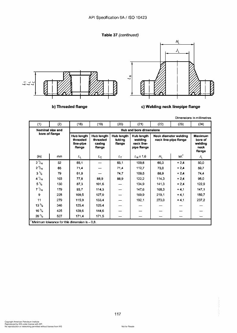
Copyright American Petroleum Institute
Reproduced by IHS under license with API
Not for ResaleNo reproduction or networking permitted without license from IHS
--`,,`,`,-`-`,,`,,`,`,,`---
API Specification 6A / ISO 10423
Table 37 (continued)
Z-.....I
b) Threaded flange c) Welding neck Iinepipe flange
Dimensions in millimetres
(1 ) (2) (18) (19) (20) (21) (22) (23) (24)
Nominal size and Hub and bore dimensionsbore of flange
Hub length Hub length Hub length Hub length Neck diameter welding Maximumthreaded threaded tubing welding neck line-pipe flange bore ofline-pipe casing flange neck line- weldingflange flange pipe flange neck
flange
(in) mm LL Lc LT LN± 1,6 HL tol.l J L
2 1/ 16 52 65,1 - 65,1 109,6 60,3 + 2,4 50,0
2 9/ 16 65 71,4 - 71,4 112,7 73,0 + 2,4 59,7
3 1/ S 79 61,9 - 74,7 109,5 88,9 + 2,4 74,4
4 1/ 16 103 77,8 88,9 88,9 122,2 114,3 + 2,4 98,0
5 1/s 130 87,3 101,6 - 134,9 141,3 + 2,4 122,9
7 1/ 16 179 93,7 114,3 - 147,6 168,3 + 4,1 147,1
9 228 109,5 127,0 - 169,9 219,1 + 4,1 189,7
11 279 115,9 133,4 - 192,1 273,0 + 4,1 237,2
13% 346 125,4 125,4 - - - - -
16 3/4 425 128,6 144,6 - - - - -
20 3/4 527 171,4 171,5 - - - - -
I Minimum tolerance for this dimension is - 0,8.
117
b) Threaded flange
(1 ) (2) (18)
Nominal size and bore of flange
Hub length threaded line-pipe flange
(in) mm LL
2 1/ 16 52 65,1
2 9/ 16 65 71,4
3 1/ 8 79 61,9
4 1/ 16 103 77,8
5 1/8 130 87,3
7 1/ 16 179 93,7
9 228 109,5
11 279 115,9
13% 346 125,4
16 3/4 425 128,6
20 3/4 527 171,4
API Specification 6A / ISO 10423
Table 37 (continued)
Z -.....I
c) Welding neck linepipe flange
Dimensions in millimetres
(19) (20) (21) (22) (23) (24)
Hub and bore dimensions
Hub length Hub length Hub length Neck diameter welding Maximum threaded tubing welding neck line-pipe flange bore of
casing flange neck line- welding flange pipe flange neck
flange
Lc LT LN ± 1,6 HL toLl JL
- 65,1 109,6 60,3 + 2,4 50,0
- 71,4 112,7 73,0 + 2,4 59,7
- 74,7 109,5 88,9 + 2,4 74,4
88,9 88,9 122,2 114,3 + 2,4 98,0
101,6 - 134,9 141,3 + 2,4 122,9
114,3 - 147,6 168,3 + 4,1 147,1
127,0 - 169,9 219,1 + 4,1 189,7
133,4 - 192,1 273,0 + 4,1 237,2
125,4 - - - - -
144,6 - - - - -
171,5 - - - - -
I Minimum tolerance for this dimension is - 0,8.
117
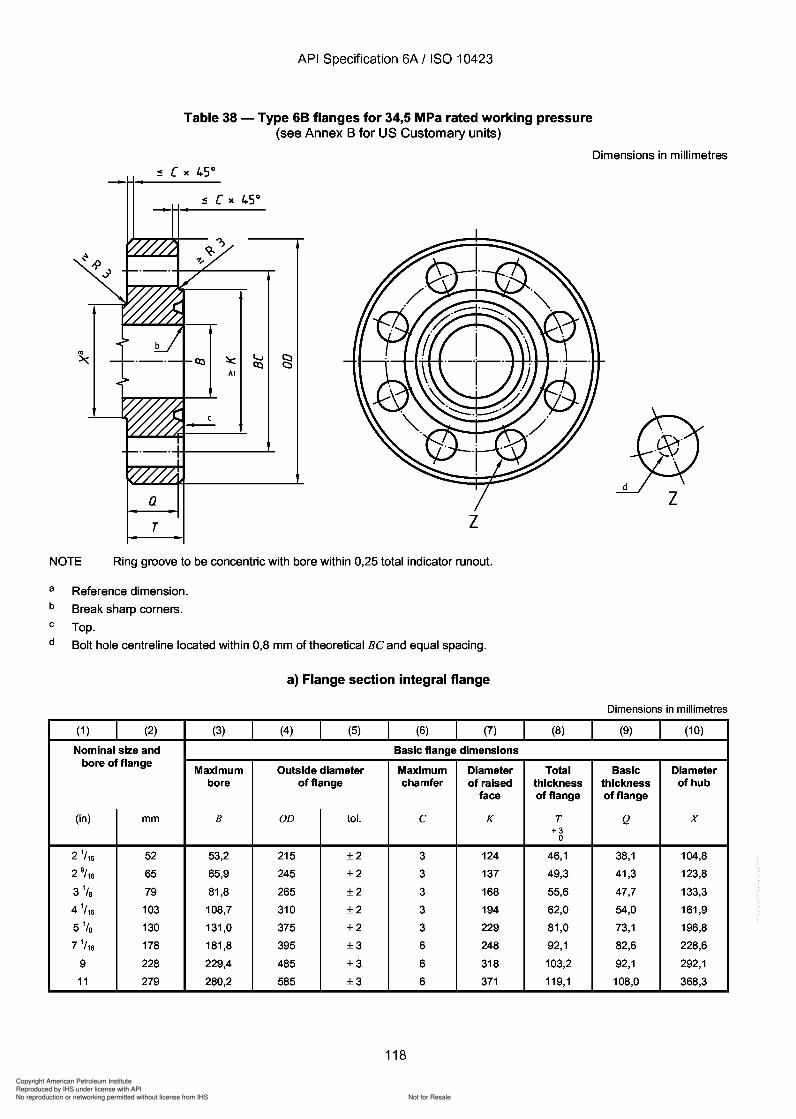
Copyright American Petroleum Institute
Reproduced by IHS under license with API
Not for ResaleNo reproduction or networking permitted without license from IHS
--`,,`,`,-`-`,,`,,`,`,,`---
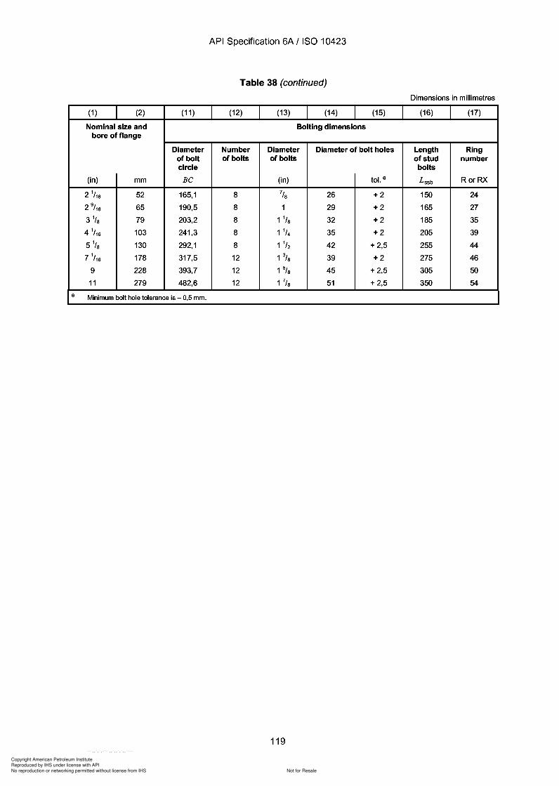
38
Copyright American Petroleum Institute
Reproduced by IHS under license with API
Not for ResaleNo reproduction or networking permitted without license from IHS
--`,,`,`,-`-`,,`,,`,`,,`---
API Specification 6A / ISO 10423
Table 38 (continued)
Dimensions in millimetres
(1 ) (2) (11 ) (12) (13) (14) (15) (16) (17)
Nominal size and Bolting dimensionsbore of flange
Diameter Number Diameter Diameter of bolt holes Length Ringof bolt of bolts of bolts of stud numbercircle bolts
(in) mm Be (in) tol. e L ssb RorRX
2 1/ 16 52 165,1 8 7/S 26 +2 150 24
2 9/ 16 65 190,5 8 1 29 +2 165 27
3 1/S 79 203,2 8 1 1/S 32 +2 185 35
4 1/ 16 103 241,3 8 1 1/4 35 +2 205 39
51/s 130 292,1 8 1 1/2 42 + 2,5 255 44
7 1/ 16 178 317,5 12 1% 39 +2 275 46
9 228 393,7 12 1% 45 + 2,5 305 50
11 279 482,6 12 1 7/S 51 + 2,5 350 54
e Minimum bolt hole tolerance is - 0,5 mm.
119
API Specification 6A / ISO 10423
Table 38 (continued)
Dimensions in millimetres
(1 ) (2) (11 ) (12) (13) (14) (15) (16) (17)
Nominal size and Bolting dimensions bore of flange
Diameter Number Diameter Diameter of bolt holes Length Ring of bolt of bolts of bolts of stud number circle bolts
(in) mm Be (in) tol. e Lssb RorRX
2 1/ 16 52 165,1 8 7/S 26 +2 150 24
2 9/ 16 65 190,5 8 1 29 +2 165 27
3 1/ S 79 203,2 8 1 1/S 32 +2 185 35
4 1/ 16 103 241,3 8 1 1/4 35 +2 205 39
51/s 130 292,1 8 1 1/2 42 + 2,5 255 44
7 1/ 16 178 317,5 12 1% 39 +2 275 46
9 228 393,7 12 1% 45 + 2,5 305 50
11 279 482,6 12 1 7/S 51 + 2,5 350 54
e Minimum bolt hole tolerance is - 0,5 mm.
119
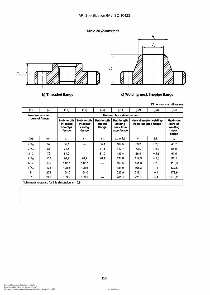
Copyright American Petroleum Institute
Reproduced by IHS under license with API
Not for ResaleNo reproduction or networking permitted without license from IHS
--`,,`,`,-`-`,,`,,`,`,,`---
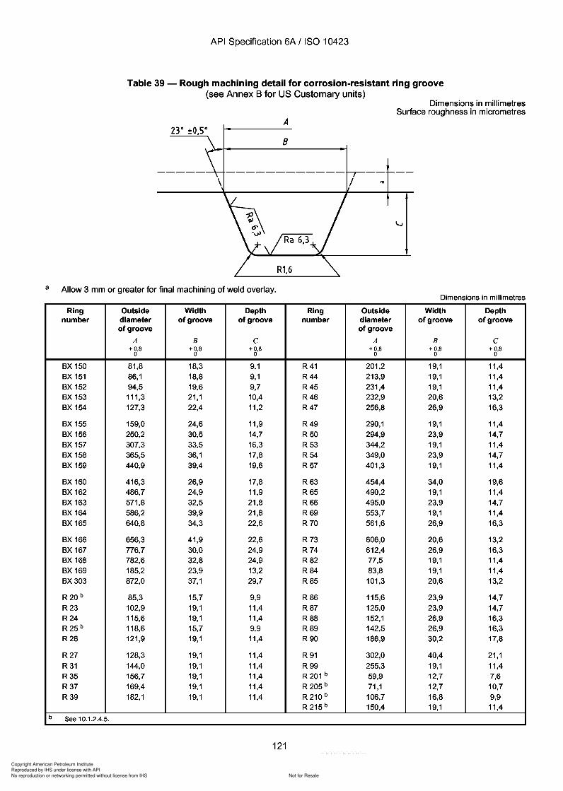
Copyright American Petroleum Institute
Reproduced by IHS under license with API
Not for ResaleNo reproduction or networking permitted without license from IHS
--`,,`,`,-`-`,,`,,`,`,,`---
API Specification 6A / ISO 10423
Table 39 - Rough machining detail for corrosion-resistant ring groove(see Annex B for US Customary units)
Dimensions in millimetresSurface roughness in micrometres
A23° ±O,so
B
10
a Allow 3 mm or greater for final machining of weld overlay.Dimensions in millimetres
Ring Outside Width Depth Ring Outside Width Depthnumber diameter of groove of groove number diameter of groove of groove
of groove of groove
A B C A B C+ 0,8 + 0,8 +0,8 +0,8 + 0,8 + 0,8
0 0 0 0 0 0
BX 150 81,8 18,3 9,1 R41 201,2 19,1 11,4BX 151 86,1 18,8 9,1 R44 213,9 19,1 11,4BX 152 94,5 19,6 9,7 R45 231,4 19,1 11,4BX 153 111,3 21,1 10,4 R46 232,9 20,6 13,2BX 154 127,3 22,4 11,2 R47 256,8 26,9 16,3
BX 155 159,0 24,6 11,9 R49 290,1 19,1 11,4BX 156 250,2 30,5 14,7 R50 294,9 23,9 14,7BX 157 307,3 33,5 16,3 R53 344,2 19,1 11,4BX 158 365,5 36,1 17,8 R54 349,0 23,9 14,7BX 159 440,9 39,4 19,6 R57 401,3 19,1 11,4
BX 160 416,3 26,9 17,8 R63 454,4 34,0 19,6BX 162 486,7 24,9 11,9 R65 490,2 19,1 11,4BX 163 571,8 32,5 21,8 R66 495,0 23,9 14,7BX 164 586,2 39,9 21,8 R69 553,7 19,1 11,4BX 165 640,8 34,3 22,6 R 70 561,6 26,9 16,3
BX 166 656,3 41,9 22,6 R 73 606,0 20,6 13,2BX 167 776,7 30,0 24,9 R 74 612,4 26,9 16,3BX 168 782,6 32,8 24,9 R82 77,5 19,1 11,4BX 169 185,2 23,9 13,2 R84 83,8 19,1 11,4BX303 872,0 37,1 29,7 R85 101,3 20,6 13,2
R20 b 85,3 15,7 9,9 R86 115,6 23,9 14,7R23 102,9 19,1 11,4 R87 125,0 23,9 14,7R24 115,6 19,1 11,4 R88 152,1 26,9 16,3R25 b 118,6 15,7 9,9 R89 142,5 26,9 16,3R26 121,9 19,1 11,4 R90 186,9 30,2 17,8
R27 128,3 19,1 11,4 R 91 302,0 40,4 21,1R31 144,0 19,1 11,4 R99 255,3 19,1 11,4R35 156,7 19,1 11,4 R 201 b 59,9 12,7 7,6R37 169,4 19,1 11,4 R 205 b 71,1 12,7 10,7R39 182,1 19,1 11,4 R 210 b 106,7 16,8 9,9
R 215 b 150,4 19,1 11,4b See 10.1.2.4.5.
121
a
b
API Specification 6A / ISO 10423
Table 39 - Rough machining detail for corrosion-resistant ring groove (see Annex B for US Customary units)
A 23° ±O,so
B
R1,6
"'
Dimensions in millimetres Surface roughness in micrometres
Allow 3 mm or greater for final machining of weld overlay. Dimensions in millimetres
Ring Outside Width Depth Ring Outside Width Depth number diameter of groove of groove number diameter of groove of groove
of groove of groove
A B C A B C + 0,8 + 0,8 +0,8 +0,8 + 0,8 + 0,8
0 0 0 0 0 0
BX 150 81,8 18,3 9,1 R41 201,2 19,1 11,4 BX 151 86,1 18,8 9,1 R44 213,9 19,1 11,4 BX 152 94,5 19,6 9,7 R45 231,4 19,1 11,4 BX 153 111,3 21,1 10,4 R46 232,9 20,6 13,2 BX 154 127,3 22,4 11,2 R47 256,8 26,9 16,3
BX 155 159,0 24,6 11,9 R49 290,1 19,1 11,4 BX 156 250,2 30,5 14,7 R50 294,9 23,9 14,7 BX 157 307,3 33,5 16,3 R53 344,2 19,1 11,4 BX 158 365,5 36,1 17,8 R54 349,0 23,9 14,7 BX 159 440,9 39,4 19,6 R57 401,3 19,1 11,4
BX 160 416,3 26,9 17,8 R63 454,4 34,0 19,6 BX 162 486,7 24,9 11,9 R65 490,2 19,1 11,4 BX 163 571,8 32,5 21,8 R66 495,0 23,9 14,7 BX 164 586,2 39,9 21,8 R69 553,7 19,1 11,4 BX 165 640,8 34,3 22,6 R 70 561,6 26,9 16,3
BX 166 656,3 41,9 22,6 R 73 606,0 20,6 13,2 BX 167 776,7 30,0 24,9 R 74 612,4 26,9 16,3 BX 168 782,6 32,8 24,9 R82 77,5 19,1 11,4 BX 169 185,2 23,9 13,2 R84 83,8 19,1 11,4 BX303 872,0 37,1 29,7 R85 101,3 20,6 13,2
R20 b 85,3 15,7 9,9 R86 115,6 23,9 14,7 R23 102,9 19,1 11,4 R87 125,0 23,9 14,7 R24 115,6 19,1 11,4 R88 152,1 26,9 16,3 R25 b 118,6 15,7 9,9 R89 142,5 26,9 16,3 R26 121,9 19,1 11,4 R90 186,9 30,2 17,8
R27 128,3 19,1 11,4 R 91 302,0 40,4 21,1
R31 144,0 19,1 11,4 R99 255,3 19,1 11,4 R35 156,7 19,1 11,4 R 201 b 59,9 12,7 7,6 R37 169,4 19,1 11,4 R 205 b 71,1 12,7 10,7 R39 182,1 19,1 11,4 R 210 b 106,7 16,8 9,9
R 215 b 150,4 19,1 11,4
See 10.1.2.4.5.
121
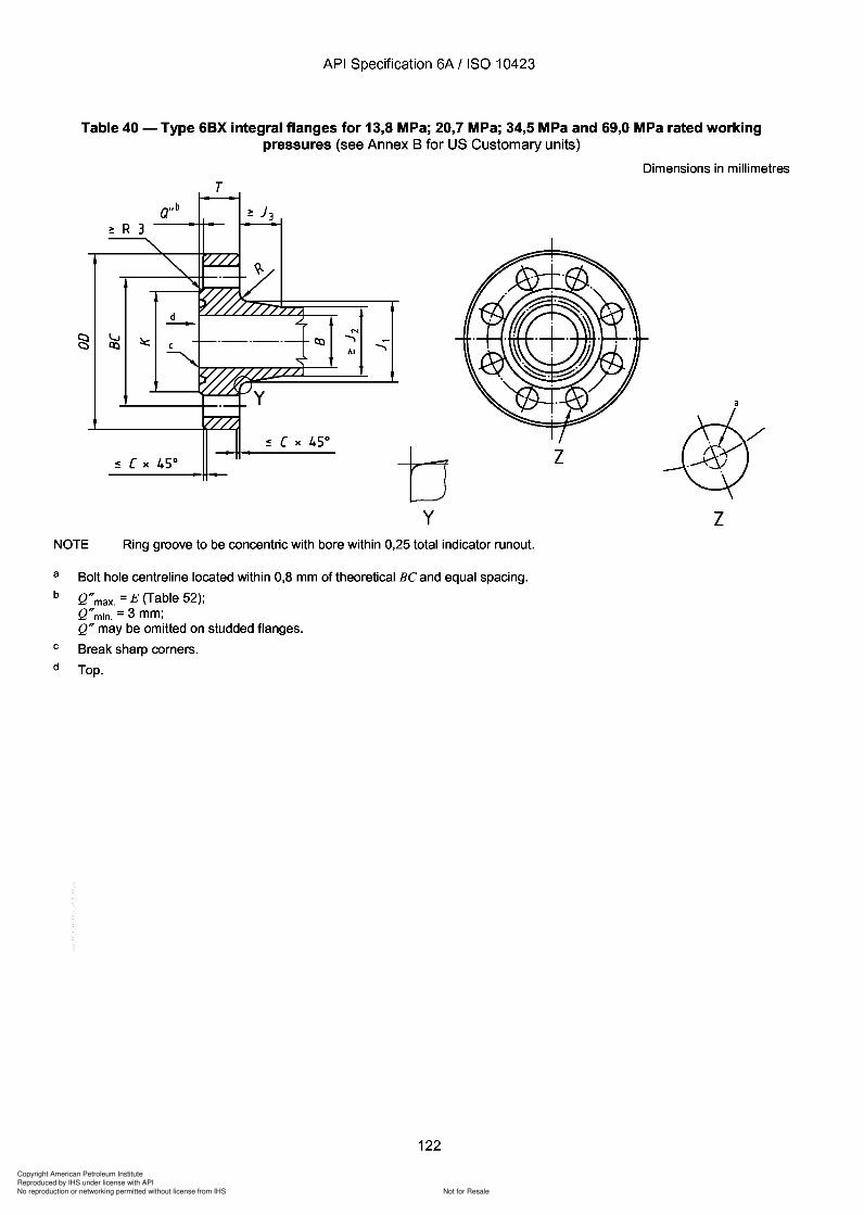
Copyright American Petroleum Institute
Reproduced by IHS under license with API
Not for ResaleNo reproduction or networking permitted without license from IHS
--`,,`,`,-`-`,,`,,`,`,,`---
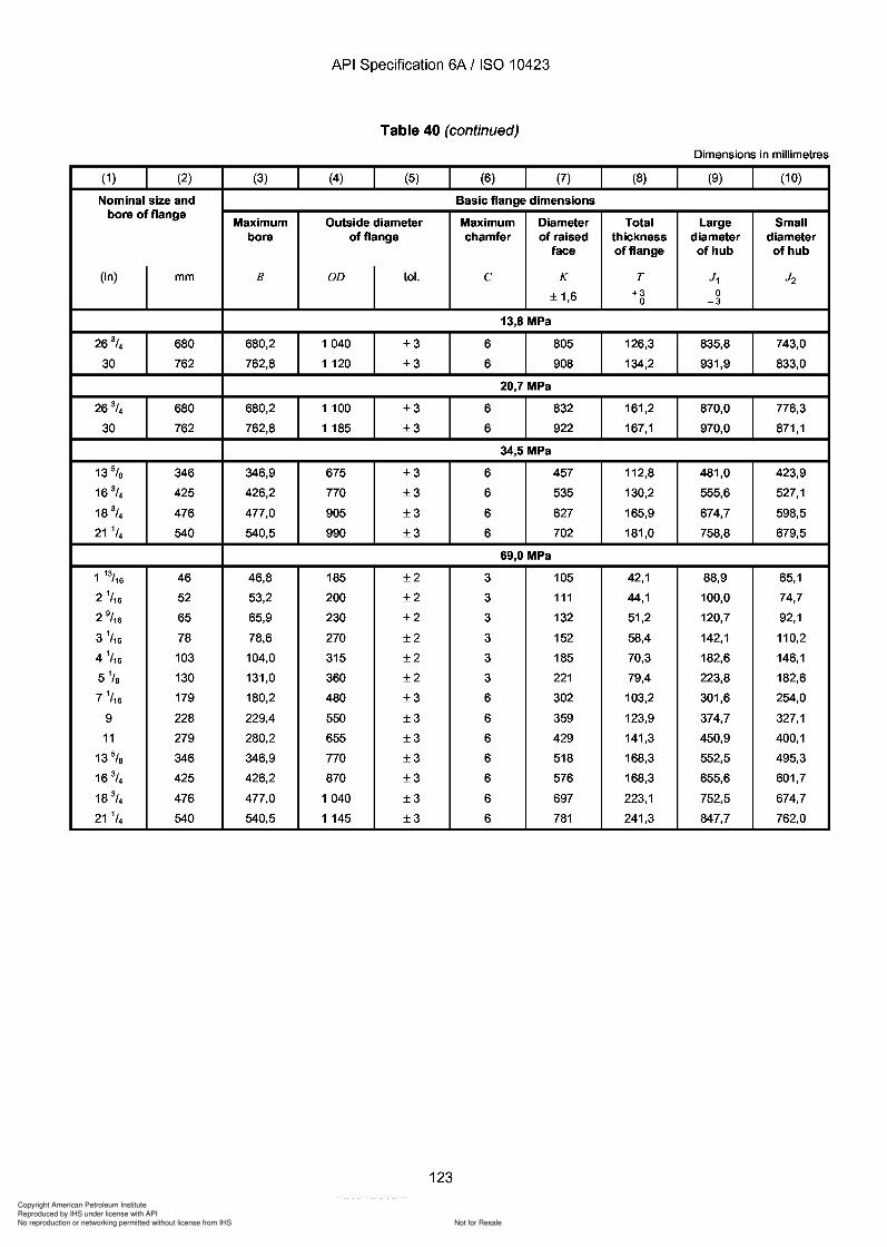
Copyright American Petroleum Institute
Reproduced by IHS under license with API
Not for ResaleNo reproduction or networking permitted without license from IHS
--`,,`,`,-`-`,,`,,`,`,,`---
API Specification 6A / ISO 10423
Table 40 (continued)
Dimensions in millimetres
(1 ) (2) (3) (4) (5) (6) (7) (8) (9) (10)
Nominal size and Basic flange dimensionsbore of flange
Maximum Outside diameter Maximum Diameter Total Large Smallbore of flange chamfer of raised thickness diameter diameter
face of flange of hub of hub
(in) mm B OD tol. C K T J1 J2
± 1,6 +3 00 -3
13,8 MPa
26 3/4 680 680,2 1040 ±3 6 805 126,3 835,8 743,0
30 762 762,8 1 120 ±3 6 908 134,2 931,9 833,0
20,7 MPa
26 3/4 680 680,2 1 100 ±3 6 832 161,2 870,0 776,3
30 762 762,8 1 185 ±3 6 922 167,1 970,0 871,1
34,5 MPa
13% 346 346,9 675 ±3 6 457 112,8 481,0 423,9
16 3/4 425 426,2 770 ±3 6 535 130,2 555,6 527,1
18 3/4 476 477,0 905 ±3 6 627 165,9 674,7 598,5
21 1/4 540 540,5 990 ±3 6 702 181,0 758,8 679,5
69,0 MPa
1 13/16 46 46,8 185 ±2 3 105 42,1 88,9 65,1
2 1/ 16 52 53,2 200 ±2 3 111 44,1 100,0 74,7
2 9/ 16 65 65,9 230 ±2 3 132 51,2 120,7 92,1
3 1/ 16 78 78,6 270 ±2 3 152 58,4 142,1 110,2
4 1/ 16 103 104,0 315 ±2 3 185 70,3 182,6 146,1
5 1/s 130 131,0 360 ±2 3 221 79,4 223,8 182,6
7 1/ 16 179 180,2 480 ±3 6 302 103,2 301,6 254,0
9 228 229,4 550 ±3 6 359 123,9 374,7 327,1
11 279 280,2 655 ±3 6 429 141,3 450,9 400,1
13% 346 346,9 770 ±3 6 518 168,3 552,5 495,3
16 3/4 425 426,2 870 ±3 6 576 168,3 655,6 601,7
18 3/4 476 477,0 1040 ±3 6 697 223,1 752,5 674,7
21 1/4 540 540,5 1 145 ±3 6 781 241,3 847,7 762,0
123
API Specification 6A / ISO 10423
Table 40 (continued)
Dimensions in millimetres
(1 ) (2) (3) (4) (5) (6) (7) (8) (9) (10)
Nominal size and Basic flange dimensions bore of flange
Maximum Outside diameter Maximum Diameter Total Large Small bore of flange chamfer of raised thickness diameter diameter
face of flange of hub of hub
(in) mm B OD tol. C K T J1 J2
± 1,6 +3 0 0 -3
13,8 MPa
26 3/4 680 680,2 1040 ±3 6 805 126,3 835,8 743,0
30 762 762,8 1 120 ±3 6 908 134,2 931,9 833,0
20,7 MPa
26 3/4 680 680,2 1 100 ±3 6 832 161,2 870,0 776,3
30 762 762,8 1 185 ±3 6 922 167,1 970,0 871,1
34,5 MPa
13% 346 346,9 675 ±3 6 457 112,8 481,0 423,9
16 3/4 425 426,2 770 ±3 6 535 130,2 555,6 527,1
18 3/4 476 477,0 905 ±3 6 627 165,9 674,7 598,5
21 1/4 540 540,5 990 ±3 6 702 181,0 758,8 679,5
69,0 MPa
1 13/16 46 46,8 185 ±2 3 105 42,1 88,9 65,1
2 1/ 16 52 53,2 200 ±2 3 111 44,1 100,0 74,7
2 9/ 16 65 65,9 230 ±2 3 132 51,2 120,7 92,1
3 1/ 16 78 78,6 270 ±2 3 152 58,4 142,1 110,2
4 1/ 16 103 104,0 315 ±2 3 185 70,3 182,6 146,1
5 1/8 130 131,0 360 ±2 3 221 79,4 223,8 182,6
7 1/ 16 179 180,2 480 ±3 6 302 103,2 301,6 254,0
9 228 229,4 550 ±3 6 359 123,9 374,7 327,1
11 279 280,2 655 ±3 6 429 141,3 450,9 400,1
13% 346 346,9 770 ±3 6 518 168,3 552,5 495,3
16 3/4 425 426,2 870 ±3 6 576 168,3 655,6 601,7
18 3/4 476 477,0 1040 ±3 6 697 223,1 752,5 674,7
21 1/4 540 540,5 1 145 ±3 6 781 241,3 847,7 762,0
123
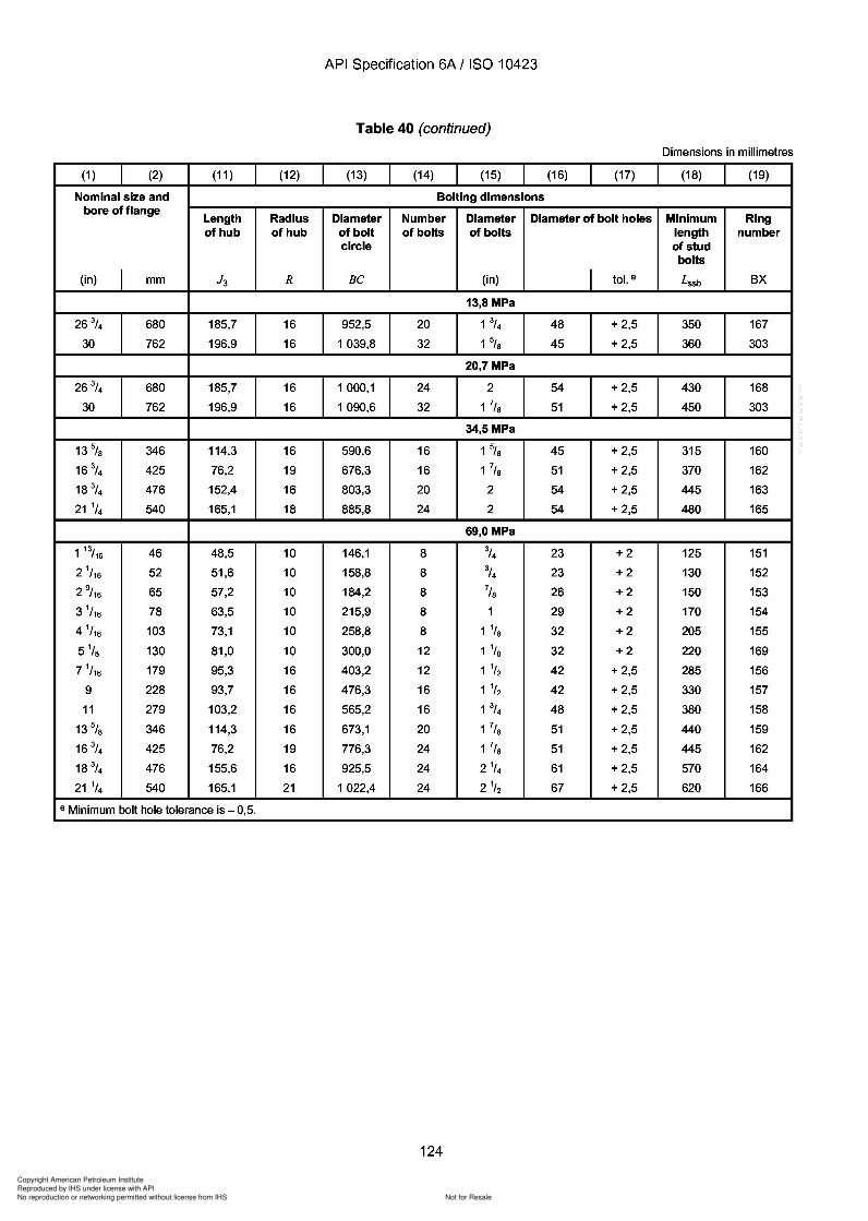
Copyright American Petroleum Institute
Reproduced by IHS under license with API
Not for ResaleNo reproduction or networking permitted without license from IHS
--`,,`,`,-`-`,,`,,`,`,,`---
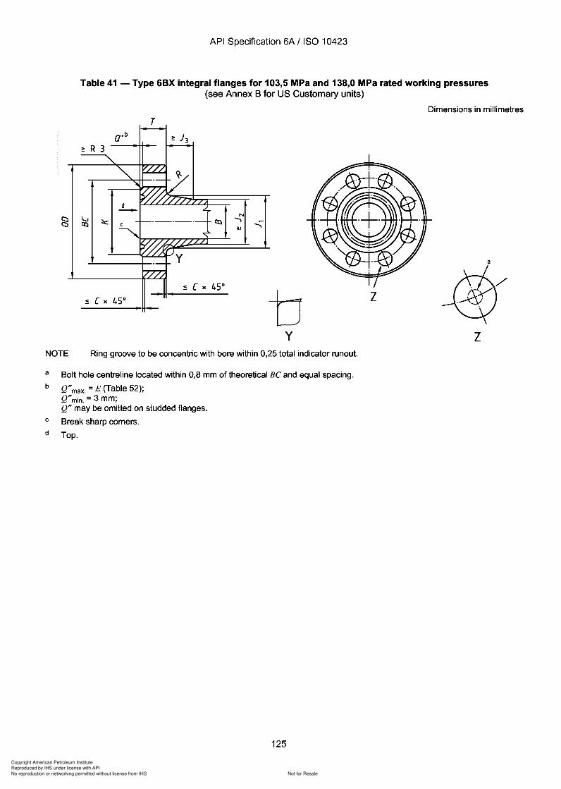
Copyright American Petroleum Institute
Reproduced by IHS under license with API
Not for ResaleNo reproduction or networking permitted without license from IHS
--`,,`,`,-`-`,,`,,`,`,,`---
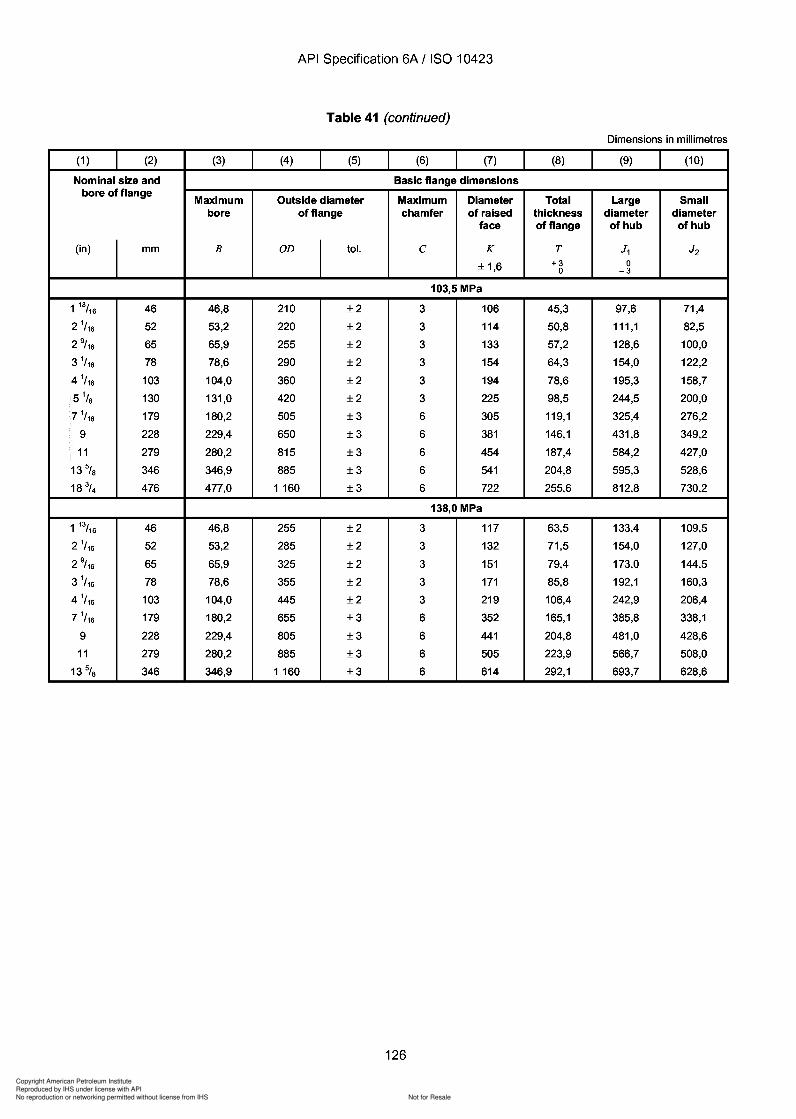
Copyright American Petroleum Institute
Reproduced by IHS under license with API
Not for ResaleNo reproduction or networking permitted without license from IHS
--`,,`,`,-`-`,,`,,`,`,,`---
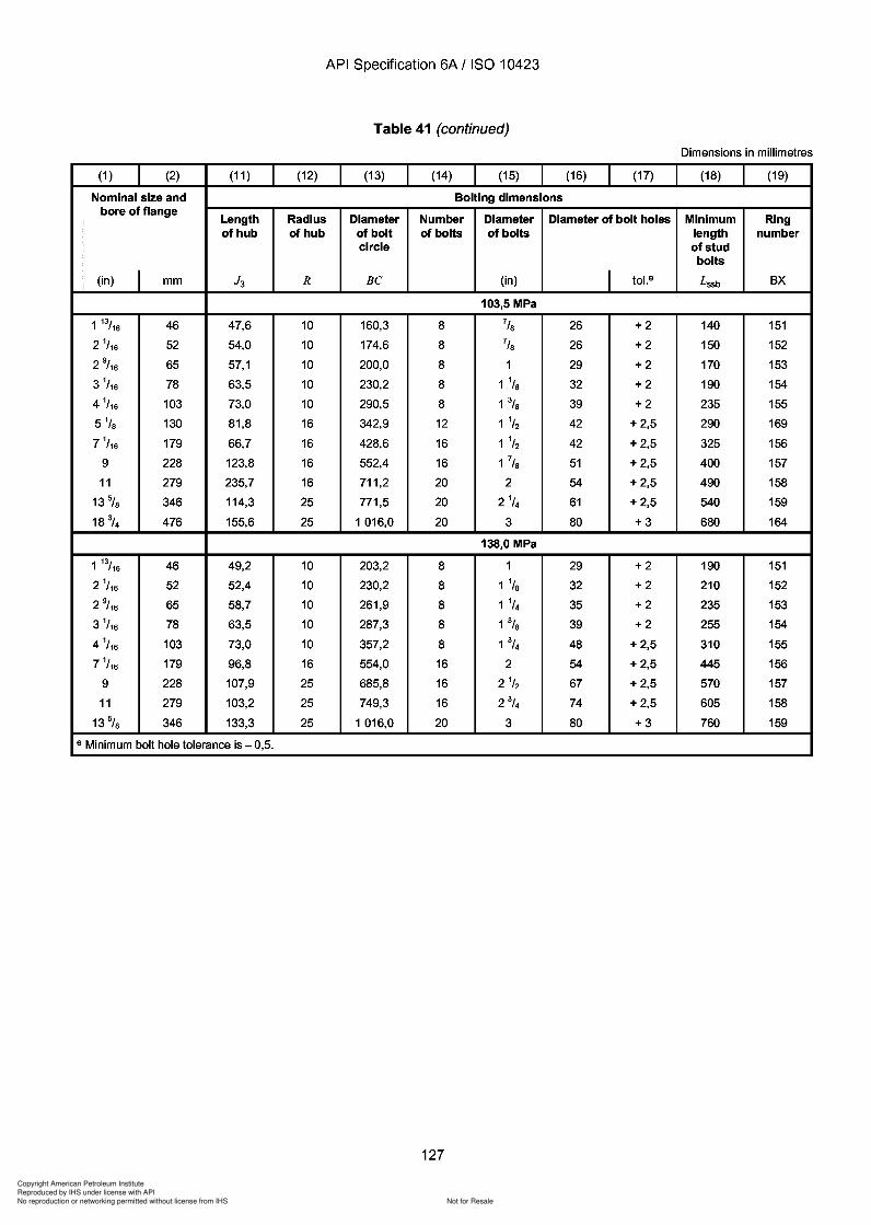
J3
Copyright American Petroleum Institute
Reproduced by IHS under license with API
Not for ResaleNo reproduction or networking permitted without license from IHS
--`,,`,`,-`-`,,`,,`,`,,`---
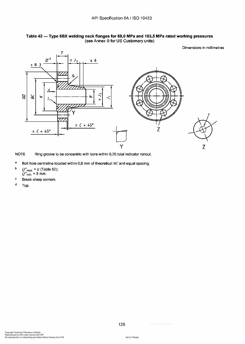
Copyright American Petroleum Institute
Reproduced by IHS under license with API
Not for ResaleNo reproduction or networking permitted without license from IHS
--`,,`,`,-`-`,,`,,`,`,,`---
API Specification 6A / ISO 10423
Table 42 - Type 6BX welding neck flanges for 69,0 MPa and 103,5 MPa rated working pressures(see Annex B for US Customary units)
Dimensions in millimetres
T
N....,AI
....,
by
z
zNOTE Ring groove to be concentric with bore within 0,25 total indicator runout.
a
b
c
d
Bolt hole centreline located within 0,8 mm of theoretical Be and equal spacing.
Q"max. = E (Table 52);Q"min. = 3 mm.
Break sharp corners.
Top.
128
API Specification 6A / ISO 10423
Table 42 - Type 6BX welding neck flanges for 69,0 MPa and 103,5 MPa rated working pressures (see Annex B for US Customary units)
Dimensions in millimetres
T
N
....... AI
b z
y z NOTE Ring groove to be concentric with bore within 0,25 total indicator runout.
a
b
c
d
Bolt hole centreline located within 0,8 mm of theoretical Be and equal spacing.
Q" max. = E (Table 52); Q" min. = 3 mm.
Break sharp corners.
Top.
128
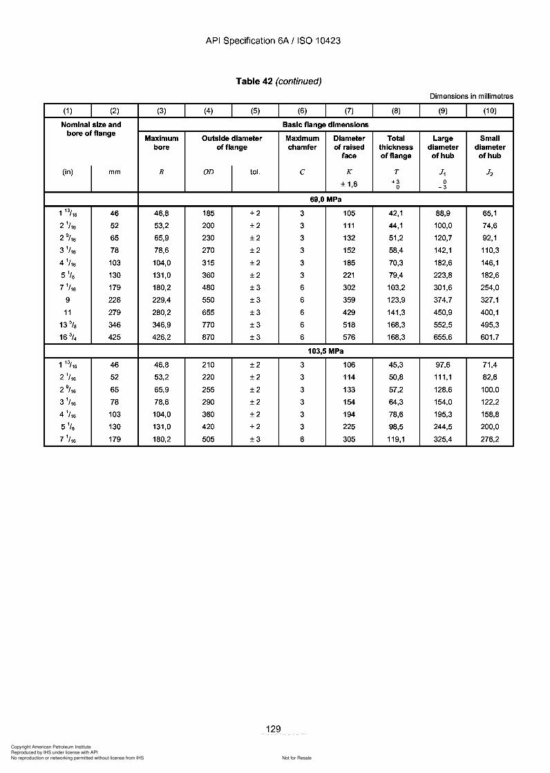
Copyright American Petroleum Institute
Reproduced by IHS under license with API
Not for ResaleNo reproduction or networking permitted without license from IHS
--`,,`,`,-`-`,,`,,`,`,,`---
API Specification 6A / ISO 10423
Table 42 (continued)
Dimensions in millimetres
(1 ) (2) (3) (4) (5) (6) (7) (8) (9) (10)
Nominal size and Basic flange dimensionsbore of flange
Maximum Outside diameter Maximum Diameter Total Large Smallbore of flange chamfer of raised thickness diameter diameter
face of flange of hub of hub
(in) mm B OD tol. C K T J1 J2
± 1,6 +3 00 -3
69,0 MPa
1 13/16 46 46,8 185 ±2 3 105 42,1 88,9 65,1
2 1/ 16 52 53,2 200 ±2 3 111 44,1 100,0 74,6
2 9/ 16 65 65,9 230 ±2 3 132 51,2 120,7 92,1
3 1/ 16 78 78,6 270 ±2 3 152 58,4 142,1 110,3
4 1/ 16 103 104,0 315 ±2 3 185 70,3 182,6 146,1
51/s 130 131,0 360 ±2 3 221 79,4 223,8 182,6
7 1/ 16 179 180,2 480 ±3 6 302 103,2 301,6 254,0
9 228 229,4 550 ±3 6 359 123,9 374,7 327,1
11 279 280,2 655 ±3 6 429 141,3 450,9 400,1
13 5/S 346 346,9 770 ±3 6 518 168,3 552,5 495,3
16 3/4 425 426,2 870 ±3 6 576 168,3 655,6 601,7
103,5 MPa
1 13/16 46 46,8 210 ±2 3 106 45,3 97,6 71,4
2 1/ 16 52 53,2 220 ±2 3 114 50,8 111,1 82,6
2 9/ 16 65 65,9 255 ±2 3 133 57,2 128,6 100,0
3 1/ 16 78 78,6 290 ±2 3 154 64,3 154,0 122,2
4 1/ 16 103 104,0 360 ±2 3 194 78,6 195,3 158,8
5 1/s 130 131,0 420 ±2 3 225 98,5 244,5 200,0
7 1/ 16 179 180,2 505 ±3 6 305 119,1 325,4 276,2
129
API Specification 6A / ISO 10423
Table 42 (continued)
Dimensions in millimetres
(1 ) (2) (3) (4) (5) (6) (7) (8) (9) (10)
Nominal size and Basic flange dimensions bore of flange
Maximum Outside diameter Maximum Diameter Total Large Small bore of flange chamfer of raised thickness diameter diameter
face of flange of hub of hub
(in) mm B OD tol. C K T J1 J2
± 1,6 +3 0 0 -3
69,0 MPa
1 13/16 46 46,8 185 ±2 3 105 42,1 88,9 65,1
2 1/ 16 52 53,2 200 ±2 3 111 44,1 100,0 74,6
2 9/ 16 65 65,9 230 ±2 3 132 51,2 120,7 92,1
3 1/ 16 78 78,6 270 ±2 3 152 58,4 142,1 110,3
4 1/ 16 103 104,0 315 ±2 3 185 70,3 182,6 146,1
51/8 130 131,0 360 ±2 3 221 79,4 223,8 182,6
7 1/ 16 179 180,2 480 ±3 6 302 103,2 301,6 254,0
9 228 229,4 550 ±3 6 359 123,9 374,7 327,1
11 279 280,2 655 ±3 6 429 141,3 450,9 400,1
13 5/8 346 346,9 770 ±3 6 518 168,3 552,5 495,3
16 3/4 425 426,2 870 ±3 6 576 168,3 655,6 601,7
103,5 MPa
1 13/16 46 46,8 210 ±2 3 106 45,3 97,6 71,4
2 1/ 16 52 53,2 220 ±2 3 114 50,8 111,1 82,6
2 9/ 16 65 65,9 255 ±2 3 133 57,2 128,6 100,0
3 1/ 16 78 78,6 290 ±2 3 154 64,3 154,0 122,2
4 1/ 16 103 104,0 360 ±2 3 194 78,6 195,3 158,8
5 1/8 130 131,0 420 ±2 3 225 98,5 244,5 200,0
7 1/ 16 179 180,2 505 ±3 6 305 119,1 325,4 276,2
129
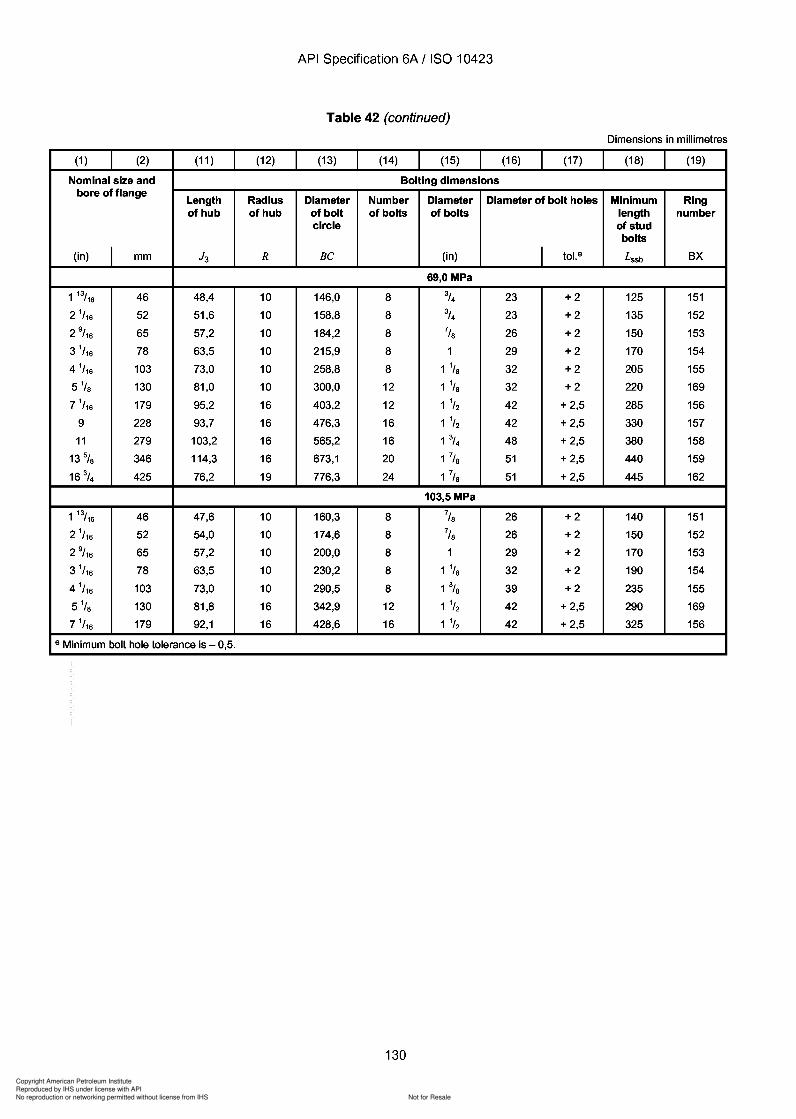
Copyright American Petroleum Institute
Reproduced by IHS under license with API
Not for ResaleNo reproduction or networking permitted without license from IHS
--`,,`,`,-`-`,,`,,`,`,,`---
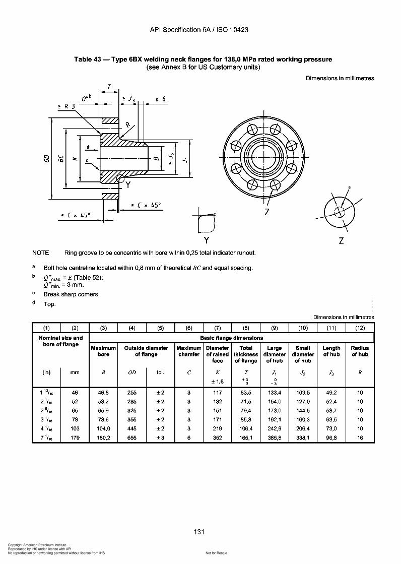
J2 J3
Copyright American Petroleum Institute
Reproduced by IHS under license with API
Not for ResaleNo reproduction or networking permitted without license from IHS
--`,,`,`,-`-`,,`,,`,`,,`---
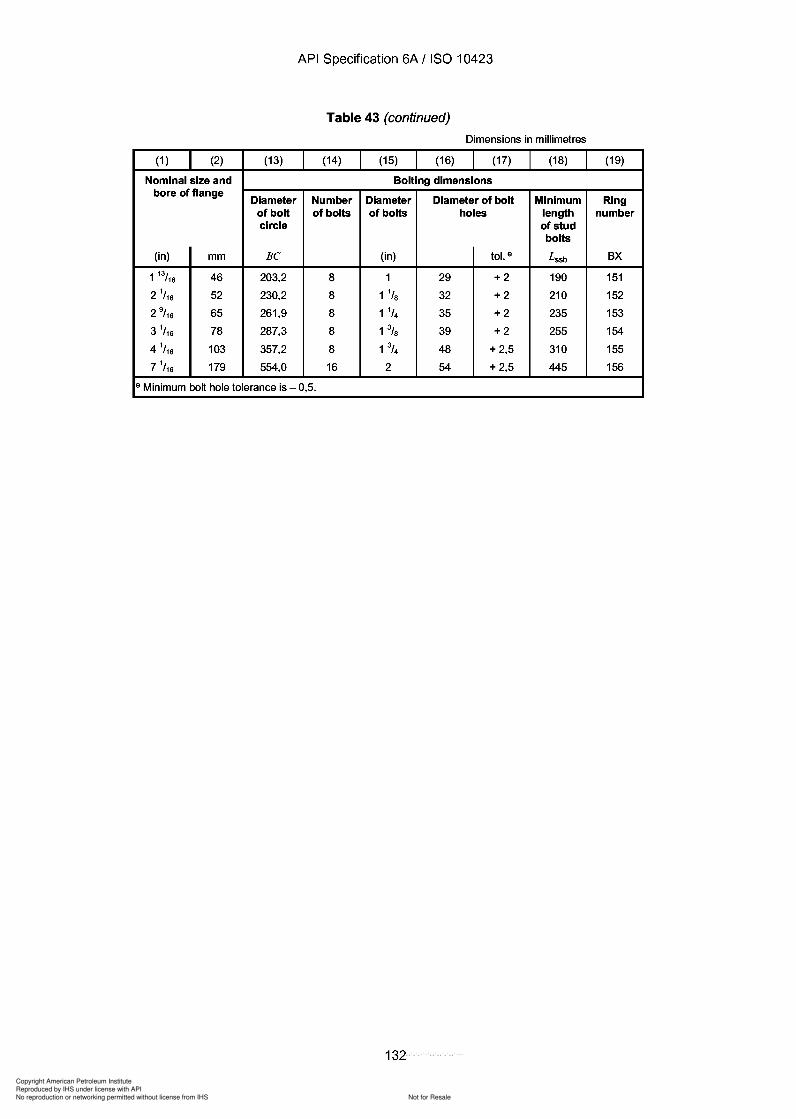
Copyright American Petroleum Institute
Reproduced by IHS under license with API
Not for ResaleNo reproduction or networking permitted without license from IHS
--`,,`,`,-`-`,,`,,`,`,,`---
API Specification 6A / ISO 10423
Table 43 (continued)
Dimensions in millimetres
(1 ) (2) (13) (14) (15) (16) (17) (18) (19)
Nominal size and Bolting dimensionsbore of flange
Diameter Number Diameter Diameter of bolt Minimum Ringof bolt of bolts of bolts holes length numbercircle of stud
bolts
(in) mm Be (in) tol. e Lssb BX
1 13/16 46 203,2 8 1 29 +2 190 151
2 1/ 16 52 230,2 8 1 1/S 32 +2 210 152
2 9/ 16 65 261,9 8 1 1/4 35 +2 235 153
3 1/ 16 78 287,3 8 1% 39 +2 255 154
4 1/ 16 103 357,2 8 1 3/4 48 + 2,5 310 155
7 1/ 16 179 554,0 16 2 54 + 2,5 445 156
e Minimum bolt hole tolerance is - 0,5.
132
API Specification 6A / ISO 10423
Table 43 (continued)
Dimensions in millimetres
(1 ) (2) (13) (14) (15) (16) (17) (18) (19)
Nominal size and Bolting dimensions bore of flange
Diameter Number Diameter Diameter of bolt Minimum Ring of bolt of bolts of bolts holes length number circle of stud
bolts
(in) mm Be (in) tol. e Lssb BX
1 13/16 46 203,2 8 1 29 +2 190 151
2 1/ 16 52 230,2 8 1 1/8 32 +2 210 152
2 9/ 16 65 261,9 8 1 1/4 35 +2 235 153
3 1/ 16 78 287,3 8 1% 39 +2 255 154
4 1/ 16 103 357,2 8 1 3/4 48 + 2,5 310 155
7 1/ 16 179 554,0 16 2 54 + 2,5 445 156
e Minimum bolt hole tolerance is - 0,5.
132
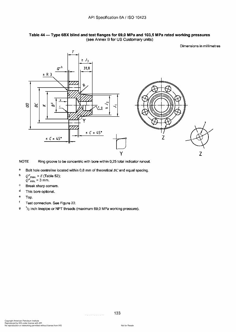
Copyright American Petroleum Institute
Reproduced by IHS under license with API
Not for ResaleNo reproduction or networking permitted without license from IHS
--`,,`,`,-`-`,,`,,`,`,,`---
API Specification 6A / ISO 10423
Table 44 - Type 6BX blind and test flanges for 69,0 MPa and 103,5 MPa rated working pressures(see Annex B for US Customary units)
Dimensions in millimetres
T
~ R 3
a"b 31,8
N
..............
y
z
zNOTE Ring groove to be concentric with bore within 0,25 total indicator runout.
a
b
c
d
e
9
Bolt hole centreline located within 0,8 mm of theoretical Be and equal spacing.
Q"max. = E (Table 52);Q"min. = 3 mm.
Break sharp corners.
This bore optional.
Top.
Test connection. See Figure 22.
1/2 inch linepipe or NPT threads (maximum 69,0 MPa working pressure).
133
API Specification 6A / ISO 10423
Table 44 - Type 6BX blind and test flanges for 69,0 MPa and 103,5 MPa rated working pressures (see Annex B for US Customary units)
Dimensions in millimetres
T
a"b 31,8
~ R 3
N
....... .......
z
y z NOTE Ring groove to be concentric with bore within 0,25 total indicator runout.
a
b
c
d
e
9
Bolt hole centreline located within 0,8 mm of theoretical Be and equal spacing.
Q" max. = E (Table 52); Q" min. = 3 mm.
Break sharp corners.
This bore optional.
Top.
Test connection. See Figure 22.
1/2 inch linepipe or NPT threads (maximum 69,0 MPa working pressure).
133
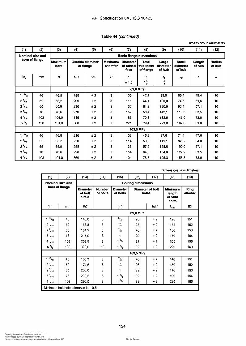
J2
J3
Copyright American Petroleum Institute
Reproduced by IHS under license with API
Not for ResaleNo reproduction or networking permitted without license from IHS
--`,,`,`,-`-`,,`,,`,`,,`---
API Specification 6A / ISO 10423
Table 44 (continued)
Dimensions in millimetres
(1 ) (2) (3) (4) (5) (6) (7) (8) (9) (10) (11 ) (12)
Nominal size and Basic flange dimensionsbore of flange
Maximum Outside diameter Maximum Diameter Total Large Small Length Radiusbore of flange chamfer of raised thickness diameter diameter of hub of hub
face of flange of hub of hub
(in) mm B OD tol. C K T J1 J2 J3 R
± 1,6 +3 00 -3
69,0 MPa
1 13/16 46 46,8 185 ±2 3 105 42,1 88,9 65,1 48,4 10
21/16 52 53,2 200 ±2 3 111 44,1 100,0 74,6 51,6 10
2 9/ 16 65 65,9 230 ±2 3 132 51,3 120,6 92,1 57,1 10
3 1/16 78 78,6 270 ±2 3 152 58,4 142,1 110,3 63,5 10
4 1/16 103 104,0 315 ±2 3 185 70,3 182,6 146,0 73,0 10
5 1/s 130 131,0 360 ±2 3 221 79,4 223,8 182,6 81,0 10
103,5 MPa
1 13/16 46 46,8 210 ±2 3 106 45,3 97,6 71,4 47,6 10
21/16 52 53,2 220 ±2 3 114 50,8 111,1 82,6 54,0 10
2 9/ 16 65 65,9 255 ±2 3 133 57,2 128,6 100,0 57,1 10
3 1/16 78 78,6 290 ±2 3 154 64,3 154,0 122,2 63,5 10
4 1/16 103 104,0 360 ±2 3 194 78,6 195,3 158,8 73,0 10
Dimensions in millimetres
(1 ) (2) (13) (14) (15) (16) (17) (18) (19)
Nominal size and Bolting dimensionsbore of flange
Diameter Number Diameter Diameter of bolt Minimum Ringof bolt of bolts of bolts holes length numbercircle of stud
bolts
(in) I mm BC (in) I tol.h Lssb BX
69,0 MPa
1 13/16 46 146,0 8 3/4 23 +2 125 151
21/16 52 158,8 8 3/4 23 +2 135 152
2 9/ 16 65 184,2 8 7/S 26 +2 150 153
3 1/16 78 215,9 8 1 29 +2 170 154
4 1/16 103 258,8 8 1 1/S 32 +2 205 155
5 1/s 130 300,0 12 1 1/S 32 +2 220 169
103,5 MPa
1 13/16 46 160,3 8 7/S 26 +2 140 151
21/16 52 174,6 8 7/S 26 +2 150 152
2 9/ 16 65 200,0 8 1 29 +2 170 153
3 1/16 78 230,2 8 1 1/S 32 +2 190 154
4 1/16 103 290,5 8 1 3/S 39 +2 235 155
h Minimum bolt hole tolerance is - 0,5.
134
API Specification 6A / ISO 10423
Table 44 (continued)
Dimensions in millimetres
(1 ) (2) (3) (4) (5) (6) (7) (8) (9) (10) (11 ) (12)
Nominal size and Basic flange dimensions bore of flange
Maximum Outside diameter Maximum Diameter Total Large Small Length Radius bore of flange chamfer of raised thickness diameter diameter of hub of hub
face of flange of hub of hub
(in) mm B OD tol. C K T J1 J2 J3 R
± 1,6 +3 0 0 -3
69,0 MPa
1 13/16 46 46,8 185 ±2 3 105 42,1 88,9 65,1 48,4 10
21/16 52 53,2 200 ±2 3 111 44,1 100,0 74,6 51,6 10
2 9/ 16 65 65,9 230 ±2 3 132 51,3 120,6 92,1 57,1 10
3 1/16 78 78,6 270 ±2 3 152 58,4 142,1 110,3 63,5 10
4 1/16 103 104,0 315 ±2 3 185 70,3 182,6 146,0 73,0 10
51/s 130 131,0 360 ±2 3 221 79,4 223,8 182,6 81,0 10
103,5 MPa
1 13/16 46 46,8 210 ±2 3 106 45,3 97,6 71,4 47,6 10
21/16 52 53,2 220 ±2 3 114 50,8 111,1 82,6 54,0 10
2 9/ 16 65 65,9 255 ±2 3 133 57,2 128,6 100,0 57,1 10
3 1/16 78 78,6 290 ±2 3 154 64,3 154,0 122,2 63,5 10
4 1/16 103 104,0 360 ±2 3 194 78,6 195,3 158,8 73,0 10
Dimensions in millimetres
(1 ) (2) (13) (14) (15) (16) (17) (18) (19)
Nominal size and Bolting dimensions bore of flange
Diameter Number Diameter Diameter of bolt Minimum Ring of bolt of bolts of bolts holes length number circle of stud
bolts
(in) I mm BC (in) I tol.h Lssb BX
69,0 MPa
1 13/16 46 146,0 8 3/4 23 +2 125 151
21/16 52 158,8 8 3/4 23 +2 135 152
2 9/ 16 65 184,2 8 7/S 26 +2 150 153
3 1/16 78 215,9 8 1 29 +2 170 154
4 1/16 103 258,8 8 1 1/S 32 +2 205 155
51/s 130 300,0 12 1 1/S 32 +2 220 169
103,5 MPa
1 13/16 46 160,3 8 7/S 26 +2 140 151
21/16 52 174,6 8 7/S 26 +2 150 152
2 9/ 16 65 200,0 8 1 29 +2 170 153
3 1/16 78 230,2 8 1 1/S 32 +2 190 154
4 1/16 103 290,5 8 1 3/S 39 +2 235 155
h Minimum bolt hole tolerance is - 0,5.
134
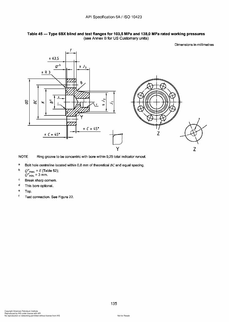
Copyright American Petroleum Institute
Reproduced by IHS under license with API
Not for ResaleNo reproduction or networking permitted without license from IHS
--`,,`,`,-`-`,,`,,`,`,,`---
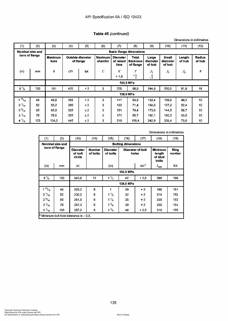
J2 J3
Copyright American Petroleum Institute
Reproduced by IHS under license with API
Not for ResaleNo reproduction or networking permitted without license from IHS
--`,,`,`,-`-`,,`,,`,`,,`---
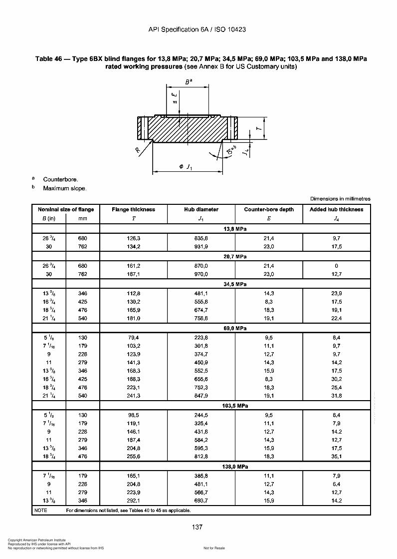
Copyright American Petroleum Institute
Reproduced by IHS under license with API
Not for ResaleNo reproduction or networking permitted without license from IHS
--`,,`,`,-`-`,,`,,`,`,,`---
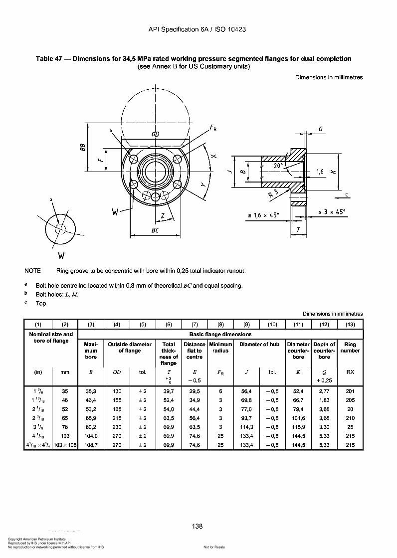
Copyright American Petroleum Institute
Reproduced by IHS under license with API
Not for ResaleNo reproduction or networking permitted without license from IHS
--`,,`,`,-`-`,,`,,`,`,,`---
API Specification 6A / ISO 10423
Table 47 - Dimensions for 34,5 MPa rated working pressure segmented flanges for dual completion(see Annex B for US Customary units)
Dimensions in millimetres
c-
Q
1,6 ~
'X
wBC
/··_·f-""", I './ , "\.. I '.! . \.
.....-------t-.-.-.-l-.-.-.+_\.. dD ../
wNOTE Ring groove to be concentric with bore within 0,25 total indicator runout.
a
b
c
Bolt hole centreline located within 0,8 mm of theoretical Be and equal spacing.
Bolt holes: L, M.
Top.
Dimensions in millimetres
(1 ) (2) (3) (4) (5) (6) (7) (8) (9) (10) (11 ) (12) (13)
Nominal size and Basic flange dimensionsbore of flange
Maxi- Outside diameter Total Distance Minimum Diameter of hub Diameter Depth of Ringmum of flange thick- flat to radius counter- counter- numberbore ness of centre bore bore
flange
(in) mm B OD tol. T E FR J tol. K Q RX+3 -0,5 + 0,250
1% 35 35,3 130 ±2 39,7 29,5 6 56,4 -0,5 52,4 2,77 2011 13/16 46 46,4 155 ±2 52,4 34,9 3 69,8 -0,5 66,7 1,83 205
2 1/ 16 52 53,2 165 ±2 54,0 44,4 3 77,0 -0,8 79,4 3,68 20
2 9/ 16 65 65,9 215 ±2 63,5 56,4 3 93,7 -0,8 101,6 3,68 210
3 1/ S 78 80,2 230 ±2 69,9 63,5 3 114,3 -0,8 115,9 3,30 25
4 1/ 16 103 104,0 270 ±2 69,9 74,6 25 133,4 -0,8 144,5 5,33 215
41/ 16 x 41
/4 103x 108 108,7 270 ±2 69,9 74,6 25 133,4 -0,8 144,5 5,33 215
138
API Specification 6A / ISO 10423
Table 47 - Dimensions for 34,5 MPa rated working pressure segmented flanges for dual completion (see Annex B for US Customary units)
w
/··_·f-··"" . I .. / . "\ .. I ..
! . \. .....-------t-.-.-.-l-.-.-.+_
\.. dD ../
w B[
NOTE Ring groove to be concentric with bore within 0,25 total indicator runout.
a
b
c
Bolt hole centreline located within 0,8 mm of theoretical Be and equal spacing.
Bolt holes: L, M.
Top.
(1 ) (2) (3) (4) (5) (6) (7) (8) (9)
Nominal size and Basic flange dimensions
(10)
bore of flange Maxi- Outside diameter Total Distance Minimum Diameter of hub mum of flange thick- flat to radius bore ness of centre
flange
(in) mm B OD tol. T E FR J tol. +3 -0,5 0
1% 35 35,3 130 ±2 39,7 29,5 6 56,4 -0,5 1 13/16 46 46,4 155 ±2 52,4 34,9 3 69,8 -0,5
2 1/ 16 52 53,2 165 ±2 54,0 44,4 3 77,0 -0,8
2 9/ 16 65 65,9 215 ±2 63,5 56,4 3 93,7 -0,8
3 1/ 8 78 80,2 230 ±2 69,9 63,5 3 114,3 -0,8
4 1/ 16 103 104,0 270 ±2 69,9 74,6 25 133,4 -0,8
41/ 16 x 41
/4 103x 108 108,7 270 ±2 69,9 74,6 25 133,4 -0,8
138
Dimensions in millimetres
Q
1,6 ~
c -
Dimensions in millimetres
(11 ) (12) (13)
Diameter Depth of Ring counter- counter- number
bore bore
K Q RX + 0,25
52,4 2,77 201
66,7 1,83 205
79,4 3,68 20
101,6 3,68 210
115,9 3,30 25
144,5 5,33 215
144,5 5,33 215
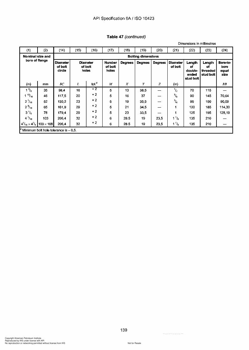
Copyright American Petroleum Institute
Reproduced by IHS under license with API
Not for ResaleNo reproduction or networking permitted without license from IHS
--`,,`,`,-`-`,,`,,`,`,,`---
API Specification 6A / ISO 10423
Table 47 (continued)
Dimensions in millimetres
(1 ) (2) (14) (15) (16) (17) (18) (19) (20) (21) (22) (23) (24)
Nominal size and Bolting dimensionsbore of flange
Diameter Diameter Number Degrees Degrees Degrees Diameter Length Length Bore-to-of bolt of bolt of bolt of bolt of of borecircle holes holes double- threaded equal
ended stud bolt sizestud bolt
(in) mm Be L tol.d M x y Z (in) BB
1% 35 98,4 16 +2 5 13 38,5 - 1/2 70 115 -1 13/16 46 117,5 20 +2 5 16 37 - % 90 145 70,64
2 1/ 16 52 130,2 23 +2 5 19 35,5 - 3/4 95 150 90,09
2 9/ 16 65 161,9 29 +2 5 21 34,5 - 1 120 185 114,30
3 1/S 78 179,4 29 +2 5 23 33,5 - 1 125 195 128,19
4 1/ 16 103 206,4 32 +2 6 28.5 19 23,5 1 1/S 135 210 -
41/ 16 X 41
/4 103x 108 206,4 32 +2 6 28.5 19 23,5 1 1/S 135 210 -
d Minimum bolt hole tolerance is - 0,5.
139
API Specification 6A / ISO 10423
Table 47 (continued)
Dimensions in millimetres
(1 ) (2) (14) (15) (16) (17) (18) (19) (20) (21) (22) (23) (24)
Nominal size and Bolting dimensions bore of flange
Diameter Diameter Number Degrees Degrees Degrees Diameter Length Length Bore-to-of bolt of bolt of bolt of bolt of of bore circle holes holes double- threaded equal
ended stud bolt size stud bolt
(in) mm Be L tol.d M X Y Z (in) BB
1% 35 98,4 16 +2 5 13 38,5 - 1/2 70 115 -1 13/16 46 117,5 20 +2 5 16 37 - % 90 145 70,64
2 1/ 16 52 130,2 23 +2 5 19 35,5 - 3/4 95 150 90,09
2 9/ 16 65 161,9 29 +2 5 21 34,5 - 1 120 185 114,30
3 1/ 8 78 179,4 29 +2 5 23 33,5 - 1 125 195 128,19
4 1/ 16 103 206,4 32 +2 6 28.5 19 23,5 1 1/8 135 210 -
41/ 16 X 41
/4 103x 108 206,4 32 +2 6 28.5 19 23,5 1 1/8 135 210 -
d Minimum bolt hole tolerance is - 0,5.
139
Copyright American Petroleum Institute
Reproduced by IHS under license with API
Not for ResaleNo reproduction or networking permitted without license from IHS
--`,,`,`,-`-`,,`,,`,`,,`---
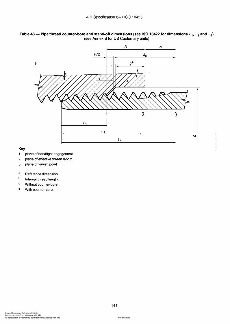
Copyright American Petroleum Institute
Reproduced by IHS under license with API
Not for ResaleNo reproduction or networking permitted without license from IHS
--`,,`,`,-`-`,,`,,`,`,,`---
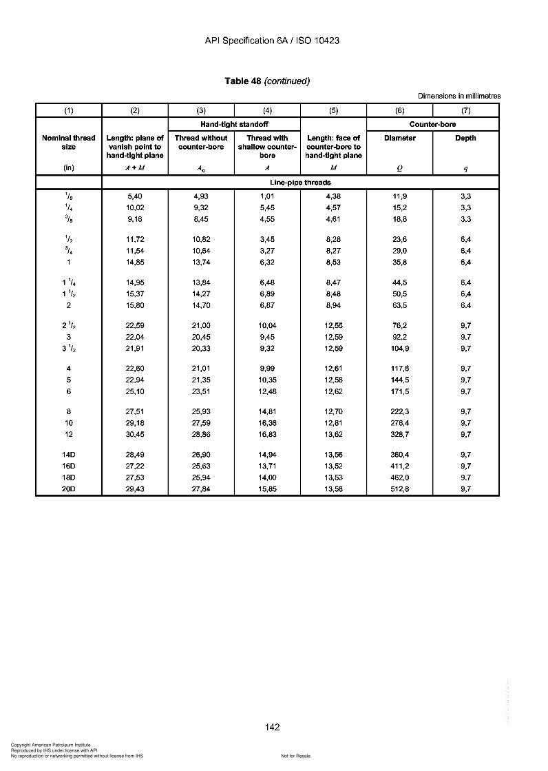
Copyright American Petroleum Institute
Reproduced by IHS under license with API
Not for ResaleNo reproduction or networking permitted without license from IHS
--`,,`,`,-`-`,,`,,`,`,,`---
API Specification 6A / ISO 10423
Table 48 (continued)
Dimensions in millimetres
(1 ) (2) (3) (4) (5) (6) (7)
Hand-tight standoff Counter-bore
Nominal thread Length: plane of Thread without Thread with Length: face of Diameter Depthsize vanish point to counter-bore shallow counter- counter-bore to
hand-tight plane bore hand-tight plane
(in) A+M Ao A M Q q
Line-pipe threads
1/S 5,40 4,93 1,01 4,38 11,9 3,31/4 10,02 9,32 5,45 4,57 15,2 3,3
% 9,16 8,45 4,55 4,61 18,8 3,3
1/2 11,72 10,82 3,45 8,28 23,6 6,43/4 11,54 10,64 3,27 8,27 29,0 6,4
1 14,85 13,74 6,32 8,53 35,8 6,4
1 1/4 14,95 13,84 6,48 8,47 44,5 6,4
1 1/2 15,37 14,27 6,89 8,48 50,5 6,4
2 15,80 14,70 6,87 8,94 63,5 6,4
2 1/ 2 22,59 21,00 10,04 12,55 76,2 9,7
3 22,04 20,45 9,45 12,59 92,2 9,7
3 1/ 2 21,91 20,33 9,32 12,59 104,9 9,7
4 22,60 21,01 9,99 12,61 117,6 9,7
5 22,94 21,35 10,35 12,58 144,5 9,7
6 25,10 23,51 12,48 12,62 171,5 9,7
8 27,51 25,93 14,81 12,70 222,3 9,7
10 29,18 27,59 16,36 12,81 276,4 9,7
12 30,45 28,86 16,83 13,62 328,7 9,7
14D 28,49 26,90 14,94 13,56 360,4 9,7
16D 27,22 25,63 13,71 13,52 411,2 9,7
18D 27,53 25,94 14,00 13,53 462,0 9,7
20D 29,43 27,84 15,85 13,58 512,8 9,7
142
API Specification 6A / ISO 10423
Table 48 (continued)
Dimensions in millimetres
(1 ) (2) (3) (4) (5) (6) (7)
Hand-tight standoff Counter-bore
Nominal thread Length: plane of Thread without Thread with Length: face of Diameter Depth size vanish point to counter-bore shallow counter- counter-bore to
hand-tight plane bore hand-tight plane
(in) A+M Ao A M Q q
Line-pipe threads
1/8 5,40 4,93 1,01 4,38 11,9 3,3
1/4 10,02 9,32 5,45 4,57 15,2 3,3
% 9,16 8,45 4,55 4,61 18,8 3,3
1/2 11,72 10,82 3,45 8,28 23,6 6,4 3/4 11,54 10,64 3,27 8,27 29,0 6,4
1 14,85 13,74 6,32 8,53 35,8 6,4
1 1/4 14,95 13,84 6,48 8,47 44,5 6,4
1 1/2 15,37 14,27 6,89 8,48 50,5 6,4
2 15,80 14,70 6,87 8,94 63,5 6,4
21/2 22,59 21,00 10,04 12,55 76,2 9,7
3 22,04 20,45 9,45 12,59 92,2 9,7
3 1/2 21,91 20,33 9,32 12,59 104,9 9,7
4 22,60 21,01 9,99 12,61 117,6 9,7
5 22,94 21,35 10,35 12,58 144,5 9,7
6 25,10 23,51 12,48 12,62 171,5 9,7
8 27,51 25,93 14,81 12,70 222,3 9,7
10 29,18 27,59 16,36 12,81 276,4 9,7
12 30,45 28,86 16,83 13,62 328,7 9,7
14D 28,49 26,90 14,94 13,56 360,4 9,7
16D 27,22 25,63 13,71 13,52 411,2 9,7
18D 27,53 25,94 14,00 13,53 462,0 9,7
20D 29,43 27,84 15,85 13,58 512,8 9,7
142
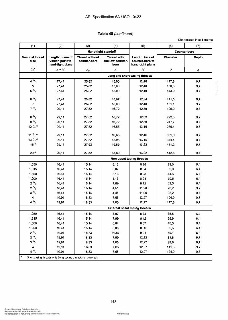
Copyright American Petroleum Institute
Reproduced by IHS under license with API
Not for ResaleNo reproduction or networking permitted without license from IHS
--`,,`,`,-`-`,,`,,`,`,,`---
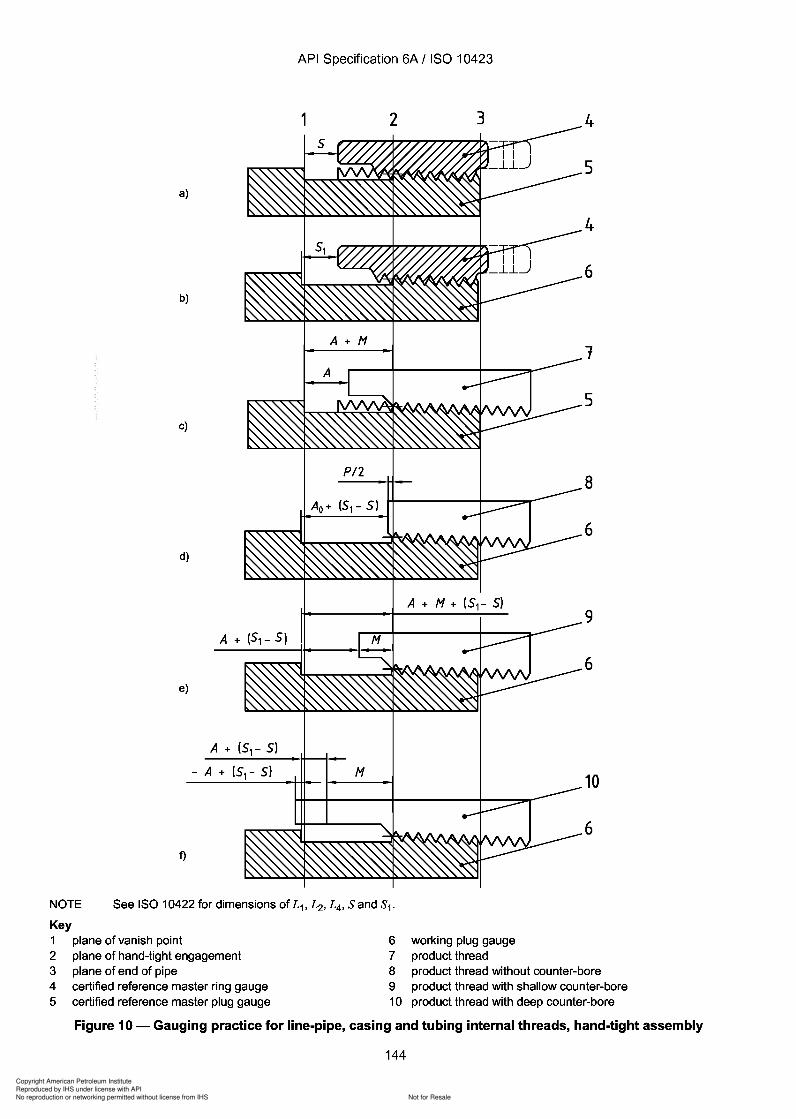
9
Copyright American Petroleum Institute
Reproduced by IHS under license with API
Not for ResaleNo reproduction or networking permitted without license from IHS
--`,,`,`,-`-`,,`,,`,`,,`---
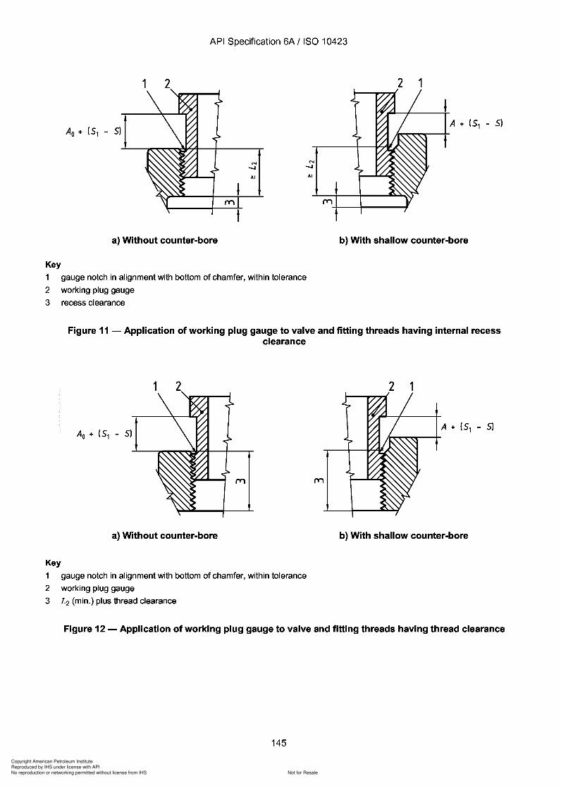
Copyright American Petroleum Institute
Reproduced by IHS under license with API
Not for ResaleNo reproduction or networking permitted without license from IHS
--`,,`,`,-`-`,,`,,`,`,,`---
Copyright American Petroleum Institute
Reproduced by IHS under license with API
Not for ResaleNo reproduction or networking permitted without license from IHS
--`,,`,`,-`-`,,`,,`,`,,`---
API Specification 6A / ISO 10423
10.3 Studs and nuts
10.3.1 General
The requirements for studs and nuts apply only to those used to connect end and outlet flanges and studdedconnections as specified in 10.1. For calculation of bolt length see Annex C, and for flange bolt torques seeAnnex D.
10.3.2 Design
The requirements for studs and nuts are shown in Table 49. Studs and nuts shall meet the requirements of theapplicable ASTM specification, unless otherwise noted. Dimensions and thread pitch shall be in accordance withASTM A 193 for studs and ASTM A 194 for nuts. The mechanical properties specified in Table 49 take precedenceover those required by ASTM.
10.3.3 Materials
10.3.3.1 General
Bolting shall meet the requirements of the applicable ASTM specifications as shown in Table 49. Alternatematerials may be used provided the mechanical properties meet the requirements shown in Table 49.
a) Yield strength
Yield strength shall meet or exceed the minimums shown in Table 49.
b) Size limitations
The material size limitations specified in ASTM A 320 for Grade L7M may be exceeded if the material requirementsare met.
10.3.3.2 NACE exposed bolting
a) ASTM A 453 Grade 660
ASTM A 453 Grade 660 solution-treated and aged-hardened is acceptable at a hardness of HRC 35 and lower,and a minimum yield strength of 725 MPa (105000 psi) for diameters up to 63,5 mm (2,5 in) or 655 MPa(95 000 psi) for larger sizes.
b) CRA materials
Other CRA materials may be used provided they satisfy the minimum mechanical requirements of ASTM A 453Grade 660 bolting except the maximum hardness shall meet NACE MR 0175 requirements.
NOTE Some materials may be susceptible to environmentally assisted cracking.
Bolting used with insulated flanges in sour service shall satisfy 10.3.3.3 (see NACE MR 0175, section 6).
10.3.3.3 NACE exposed bolting (low strength)
a) ASTM A 193 Grade B7M
ASTM A 193 Grade B7M is acceptable at a minimum yield strength of 550 MPa (80000 psi) for the flanges listed inTable 49 for NACE MR 0175 exposed bolting (low strength) only.
b) ASTM A 320 Grade L7M
ASTM A 320 Grade L7M is acceptable at a minimum yield strength of 550 MPa (80000 psi) for the flanges listed inTable 49 for NACE MR 0175 exposed bolting (low strength) only.
146
API Specification 6A / ISO 10423
10.3 Studs and nuts
10.3.1 General
The requirements for studs and nuts apply only to those used to connect end and outlet flanges and studded connections as specified in 10.1. For calculation of bolt length see Annex C, and for flange bolt torques see Annex D.
10.3.2 Design
The requirements for studs and nuts are shown in Table 49. Studs and nuts shall meet the requirements of the applicable ASTM specification, unless otherwise noted. Dimensions and thread pitch shall be in accordance with ASTM A 193 for studs and ASTM A 194 for nuts. The mechanical properties specified in Table 49 take precedence over those required by ASTM.
10.3.3 Materials
10.3.3.1 General
Bolting shall meet the requirements of the applicable ASTM specifications as shown in Table 49. Alternate materials may be used provided the mechanical properties meet the requirements shown in Table 49.
a) Yield strength
Yield strength shall meet or exceed the minimums shown in Table 49.
b) Size limitations
The material size limitations specified in ASTM A 320 for Grade L7M may be exceeded if the material requirements are met.
10.3.3.2 NACE exposed bolting
a) ASTM A 453 Grade 660
ASTM A 453 Grade 660 solution-treated and aged-hardened is acceptable at a hardness of HRC 35 and lower, and a minimum yield strength of 725 MPa (105000 psi) for diameters up to 63,5 mm (2,5 in) or 655 MPa (95 000 psi) for larger sizes.
b) CRA materials
Other CRA materials may be used provided they satisfy the minimum mechanical requirements of ASTM A 453 Grade 660 bolting except the maximum hardness shall meet NACE MR 0175 requirements.
NOTE Some materials may be susceptible to environmentally assisted cracking.
Bolting used with insulated flanges in sour service shall satisfy 10.3.3.3 (see NACE MR 0175, section 6).
10.3.3.3 NACE exposed bolting (low strength)
a) ASTM A 193 Grade B7M
ASTM A 193 Grade B7M is acceptable at a minimum yield strength of 550 MPa (80000 psi) for the flanges listed in Table 49 for NACE MR 0175 exposed bolting (low strength) only.
b) ASTM A 320 Grade L7M
ASTM A 320 Grade L7M is acceptable at a minimum yield strength of 550 MPa (80000 psi) for the flanges listed in Table 49 for NACE MR 0175 exposed bolting (low strength) only.
146
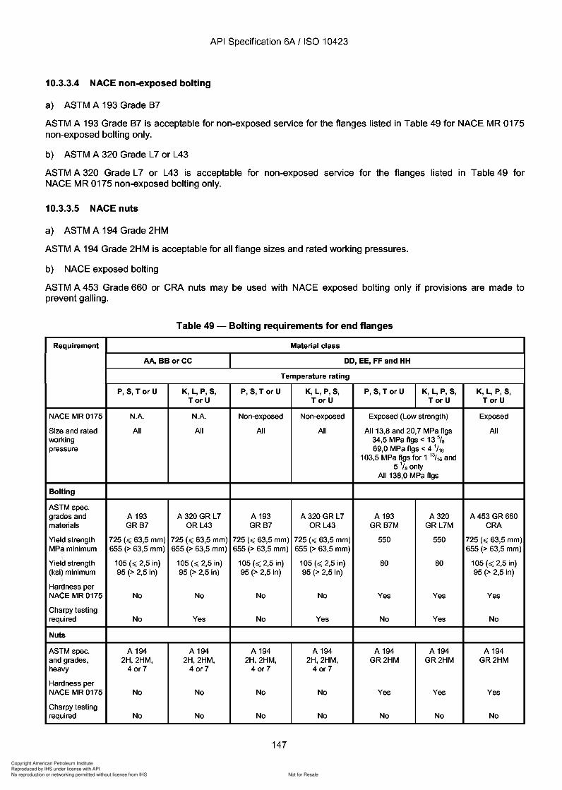
343
Copyright American Petroleum Institute
Reproduced by IHS under license with API
Not for ResaleNo reproduction or networking permitted without license from IHS
--`,,`,`,-`-`,,`,,`,`,,`---
Copyright American Petroleum Institute
Reproduced by IHS under license with API
Not for ResaleNo reproduction or networking permitted without license from IHS
--`,,`,`,-`-`,,`,,`,`,,`---
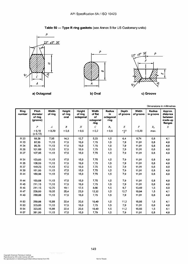
Copyright American Petroleum Institute
Reproduced by IHS under license with API
Not for ResaleNo reproduction or networking permitted without license from IHS
--`,,`,`,-`-`,,`,,`,`,,`---
API Specification 6A / ISO 10423
Table 50 - Type R ring gaskets (see Annex B for US Customary units)
p
A
a) Octagonal
p
A
b) Oval c) Groove
Dimensions in millimetres
Ring Pitch Width Height Height Width Radius Depth Width Radius Approx.number diameter of ring of ring of ring of flat in of groove of groove in groove distance
of ring oval octagonal of octagonal between(groove) octagonal ring made-up
ring flangesp A B H C R1 E F R2 S
±0,18 ±0,20 ±0,5 ±0,5 ±0,2 ±0,5 +0,5 ±0,20 max.(±0,13)
0
R20 68,28 7,95 14,3 12,7 5,23 1,5 6,4 8,74 0,8 4,1R23 82,55 11,13 17,5 15,9 7,75 1,5 7,9 11,91 0,8 4,8R24 95,25 11,13 17,5 15,9 7,75 1,5 7,9 11,91 0,8 4,8R26 101,60 11,13 17,5 15,9 7,75 1,5 7,9 11,91 0,8 4,8R27 107,95 11,13 17,5 15,9 7,75 1,5 7,9 11,91 0,8 4,8
R 31 123,83 11,13 17,5 15,9 7,75 1,5 7,9 11,91 0,8 4,8R35 136,53 11,13 17,5 15,9 7,75 1,5 7,9 11,91 0,8 4,8R37 149,23 11,13 17,5 15,9 7,75 1,5 7,9 11,91 0,8 4,8R39 161,93 11,13 17,5 15,9 7,75 1,5 7,9 11,91 0,8 4,8R41 180,98 11,13 17,5 15,9 7,75 1,5 7,9 11,91 0,8 4,8
R44 193,68 11,13 17,5 15,9 7,75 1,5 7,9 11,91 0,8 4,8R45 211,15 11,13 17,5 15,9 7,75 1,5 7,9 11,91 0,8 4,8R46 211,15 12,70 19,1 17,5 8,66 1,5 9,7 13,49 1,5 4,8R47 228,60 19,05 25,4 23,9 12,32 1,5 12,7 19,84 1,5 4,1R49 269,88 11,13 17,5 15,9 7,75 1,5 7,9 11,91 0,8 4,8
R50 269,88 15,88 22,4 20,6 10,49 1,5 11,2 16,66 1,5 4,1R53 323,85 11,13 17,5 15,9 7,75 1,5 7,9 11,91 0,8 4,8R54 323,85 15,88 22,4 20,6 10,49 1,5 11,2 16,66 1,5 4,1R57 381,00 11,13 17,5 15,9 7,79 1,5 7,9 11,91 0,8 4,8
149
API Specification 6A / ISO 10423
Table 50 - Type R ring gaskets (see Annex B for US Customary units)
p
p
A A
a) Octagonal b) Oval c) Groove
Dimensions in millimetres
Ring Pitch Width Height Height Width Radius Depth Width Radius Approx. number diameter of ring of ring of ring of flat in of groove of groove in groove distance
of ring oval octagonal of octagonal between (groove) octagonal ring made-up
ring flanges p A B H C R1 E F R2 S
±0,18 ±0,20 ±0,5 ±0,5 ±0,2 ±0,5 +0,5 ±0,20 max. (±0,13)
0
R20 68,28 7,95 14,3 12,7 5,23 1,5 6,4 8,74 0,8 4,1 R23 82,55 11,13 17,5 15,9 7,75 1,5 7,9 11,91 0,8 4,8 R24 95,25 11,13 17,5 15,9 7,75 1,5 7,9 11,91 0,8 4,8 R26 101,60 11,13 17,5 15,9 7,75 1,5 7,9 11,91 0,8 4,8 R27 107,95 11,13 17,5 15,9 7,75 1,5 7,9 11,91 0,8 4,8
R 31 123,83 11,13 17,5 15,9 7,75 1,5 7,9 11,91 0,8 4,8 R35 136,53 11,13 17,5 15,9 7,75 1,5 7,9 11,91 0,8 4,8 R37 149,23 11,13 17,5 15,9 7,75 1,5 7,9 11,91 0,8 4,8 R39 161,93 11,13 17,5 15,9 7,75 1,5 7,9 11,91 0,8 4,8 R41 180,98 11,13 17,5 15,9 7,75 1,5 7,9 11,91 0,8 4,8
R44 193,68 11,13 17,5 15,9 7,75 1,5 7,9 11,91 0,8 4,8 R45 211,15 11,13 17,5 15,9 7,75 1,5 7,9 11,91 0,8 4,8 R46 211,15 12,70 19,1 17,5 8,66 1,5 9,7 13,49 1,5 4,8 R47 228,60 19,Q5 25,4 23,9 12,32 1,5 12,7 19,84 1,5 4,1 R49 269,88 11,13 17,5 15,9 7,75 1,5 7,9 11,91 0,8 4,8
R50 269,88 15,88 22,4 20,6 10,49 1,5 11,2 16,66 1,5 4,1 R53 323,85 11,13 17,5 15,9 7,75 1,5 7,9 11,91 0,8 4,8 R54 323,85 15,88 22,4 20,6 10,49 1,5 11,2 16,66 1,5 4,1 R57 381,00 11,13 17,5 15,9 7,79 1,5 7,9 11,91 0,8 4,8
149
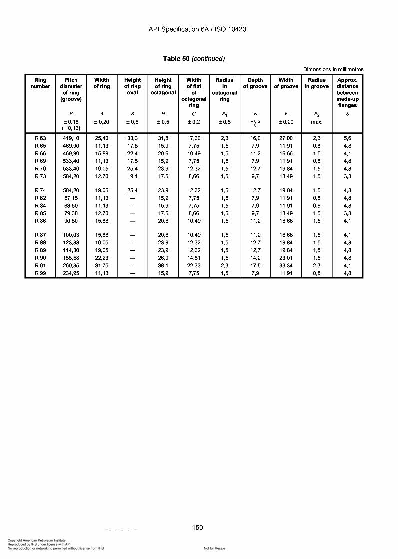
Copyright American Petroleum Institute
Reproduced by IHS under license with API
Not for ResaleNo reproduction or networking permitted without license from IHS
--`,,`,`,-`-`,,`,,`,`,,`---
API Specification 6A / ISO 10423
Table 50 (continued)
Dimensions in millimetres
Ring Pitch Width Height Height Width Radius Depth Width Radius Approx.number diameter of ring of ring of ring of flat in of groove of groove in groove distance
of ring oval octagonal of octagonal between(groove) octagonal ring made-up
ring flangesp A B H C R1 E F R2 S
±0,18 ±0,20 ±0,5 ±0,5 ±0,2 ±0,5 + 0,5 ±0,20 max.(±0,13)
0
R63 419,10 25,40 33,3 31,8 17,30 2,3 16,0 27,00 2,3 5,6R65 469,90 11,13 17,5 15,9 7,75 1,5 7,9 11,91 0,8 4,8R66 469,90 15,88 22,4 20,6 10,49 1,5 11,2 16,66 1,5 4,1R69 533,40 11,13 17,5 15,9 7,75 1,5 7,9 11,91 0,8 4,8R70 533,40 19,05 25,4 23,9 12,32 1,5 12,7 19,84 1,5 4,8R73 584,20 12,70 19,1 17,5 8,66 1,5 9,7 13,49 1,5 3,3
R74 584,20 19,05 25,4 23,9 12,32 1,5 12,7 19,84 1,5 4,8R82 57,15 11,13 - 15,9 7,75 1,5 7,9 11,91 0,8 4,8R84 63,50 11,13 - 15,9 7,75 1,5 7,9 11,91 0,8 4,8R85 79,38 12,70 - 17,5 8,66 1,5 9,7 13,49 1,5 3,3R86 90,50 15,88 - 20,6 10,49 1,5 11,2 16,66 1,5 4,1
R87 100,03 15,88 - 20,6 10,49 1,5 11,2 16,66 1,5 4,1R88 123,83 19,05 - 23,9 12,32 1,5 12,7 19,84 1,5 4,8R89 114,30 19,05 - 23,9 12,32 1,5 12,7 19,84 1,5 4,8R90 155,58 22,23 - 26,9 14,81 1,5 14,2 23,01 1,5 4,8R91 260,35 31,75 - 38,1 22,33 2,3 17,5 33,34 2,3 4,1R99 234,95 11,13 - 15,9 7,75 1,5 7,9 11,91 0,8 4,8
150
API Specification 6A / ISO 10423
Table 50 (continued)
Dimensions in millimetres
Ring Pitch Width Height Height Width Radius Depth Width Radius Approx. number diameter of ring of ring of ring of flat in of groove of groove in groove distance
of ring oval octagonal of octagonal between (groove) octagonal ring made-up
ring flanges p A B H C R1 E F R2 S
±0,18 ±0,20 ±0,5 ±0,5 ±0,2 ±0,5 + 0,5 ±0,20 max. (±0,13)
0
R63 419,10 25,40 33,3 31,8 17,30 2,3 16,0 27,00 2,3 5,6 R65 469,90 11,13 17,5 15,9 7,75 1,5 7,9 11,91 0,8 4,8 R66 469,90 15,88 22,4 20,6 10,49 1,5 11,2 16,66 1,5 4,1 R69 533,40 11,13 17,5 15,9 7,75 1,5 7,9 11,91 0,8 4,8 R70 533,40 19,05 25,4 23,9 12,32 1,5 12,7 19,84 1,5 4,8 R73 584,20 12,70 19,1 17,5 8,66 1,5 9,7 13,49 1,5 3,3
R74 584,20 19,05 25,4 23,9 12,32 1,5 12,7 19,84 1,5 4,8 R82 57,15 11,13 - 15,9 7,75 1,5 7,9 11,91 0,8 4,8 R84 63,50 11,13 - 15,9 7,75 1,5 7,9 11,91 0,8 4,8 R85 79,38 12,70 - 17,5 8,66 1,5 9,7 13,49 1,5 3,3 R86 90,50 15,88 - 20,6 10,49 1,5 11,2 16,66 1,5 4,1
R87 100,03 15,88 - 20,6 10,49 1,5 11,2 16,66 1,5 4,1 R88 123,83 19,05 - 23,9 12,32 1,5 12,7 19,84 1,5 4,8 R89 114,30 19,05 - 23,9 12,32 1,5 12,7 19,84 1,5 4,8 R90 155,58 22,23 - 26,9 14,81 1,5 14,2 23,01 1,5 4,8 R91 260,35 31,75 - 38,1 22,33 2,3 17,5 33,34 2,3 4,1 R99 234,95 11,13 - 15,9 7,75 1,5 7,9 11,91 0,8 4,8
150
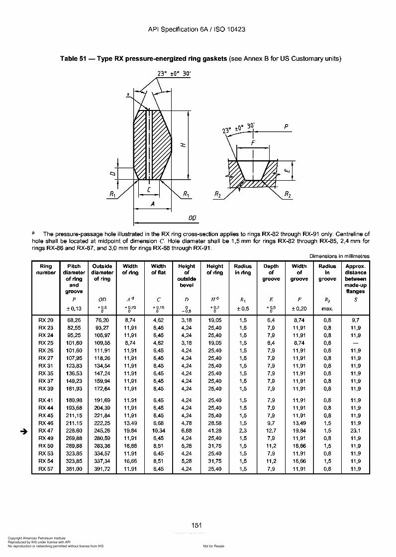
Copyright American Petroleum Institute
Reproduced by IHS under license with API
Not for ResaleNo reproduction or networking permitted without license from IHS
--`,,`,`,-`-`,,`,,`,`,,`---
API Specification 6A / ISO 10423
Table 51 - Type RX pressure-energized ring gaskets (see Annex B for US Customary units)
A
OD
a The pressure-passage hole illustrated in the RX ring cross-section applies to rings RX-82 through RX-91 only. Centreline ofhole shall be located at midpoint of dimension C. Hole diameter shall be 1,5 mm for rings RX-82 through RX-85, 2,4 mm forrings RX-86 and RX-87, and 3,0 mm for rings RX-88 through RX-91.
Dimensions in millimetres
Ring Pitch Outside Width Width Height Height Radius Depth Width Radius Approx.number diameter diameter of ring of flat of of ring in ring of of in distance
of ring of ring outside groove groove groove betweenand bevel made-up
groove flangesp OD Ad C D Hd R1 E F R2 S
±0,13 +0,5 +0,20 + 0,15 0 +0,2 ±0,5 + 0,5 ±0,20 max.0 0 0 -0,8 0 0
RX20 68,26 76,20 8,74 4,62 3,18 19,05 1,5 6,4 8,74 0,8 9,7RX23 82,55 93,27 11,91 6,45 4,24 25,40 1,5 7,9 11,91 0,8 11,9RX24 95,25 105,97 11,91 6,45 4,24 25,40 1,5 7,9 11,91 0,8 11,9RX25 101,60 109,55 8,74 4,62 3,18 19,05 1,5 6,4 8,74 0,8 -RX26 101,60 111,91 11,91 6,45 4,24 25,40 1,5 7,9 11,91 0,8 11,9RX27 107,95 118,26 11,91 6,45 4,24 25,40 1,5 7,9 11,91 0,8 11,9RX31 123,83 134,54 11,91 6,45 4,24 25,40 1,5 7,9 11,91 0,8 11,9RX35 136,53 147,24 11,91 6,45 4,24 25,40 1,5 7,9 11,91 0,8 11,9RX37 149,23 159,94 11,91 6,45 4,24 25,40 1,5 7,9 11,91 0,8 11,9RX39 161,93 172,64 11,91 6,45 4,24 25,40 1,5 7,9 11,91 0,8 11,9
RX41 180,98 191,69 11,91 6,45 4,24 25,40 1,5 7,9 11,91 0,8 11,9RX44 193,68 204,39 11,91 6,45 4,24 25,40 1,5 7,9 11,91 0,8 11,9RX45 211,15 221,84 11,91 6,45 4,24 25,40 1,5 7,9 11,91 0,8 11,9RX46 211,15 222,25 13,49 6,68 4,78 28,58 1,5 9,7 13,49 1,5 11,9RX47 228,60 245,26 19,84 10,34 6,88 41,28 2,3 12,7 19,84 1,5 23,1RX49 269,88 280,59 11,91 6,45 4,24 25,40 1,5 7,9 11,91 0,8 11,9RX50 269,88 283,36 16,66 8,51 5,28 31,75 1,5 11,2 16,66 1,5 11,9RX53 323,85 334,57 11,91 6,45 4,24 25,40 1,5 7,9 11,91 0,8 11,9RX54 323,85 337,34 16,66 8,51 5,28 31,75 1,5 11,2 16,66 1,5 11,9RX57 381,00 391,72 11,91 6,45 4,24 25,40 1,5 7,9 11,91 0,8 11,9
151
API Specification 6A / ISO 10423
Table 51 - Type RX pressure-energized ring gaskets (see Annex B for US Customary units)
A
00
a The pressure-passage hole illustrated in the RX ring cross-section applies to rings RX-82 through RX-91 only. Centreline of hole shall be located at midpoint of dimension C. Hole diameter shall be 1,5 mm for rings RX-82 through RX-85, 2,4 mm for rings RX-86 and RX-87, and 3,0 mm for rings RX-88 through RX-91.
Dimensions in millimetres
Ring Pitch Outside Width Width Height Height Radius Depth Width Radius Approx. number diameter diameter of ring of flat of of ring in ring of of in distance
of ring of ring outside groove groove groove between and bevel made-up
groove flanges p OD Ad C D Hd R1 E F R2 S
±0,13 +0,5 +0,20 + 0,15 0 +0,2 ±0,5 + 0,5 ±0,20 max. 0 0 0 -0,8 0 0
RX20 68,26 76,20 8,74 4,62 3,18 19,05 1,5 6,4 8,74 0,8 9,7 RX23 82,55 93,27 11,91 6,45 4,24 25,40 1,5 7,9 11,91 0,8 11,9 RX24 95,25 105,97 11,91 6,45 4,24 25,40 1,5 7,9 11,91 0,8 11,9 RX25 101,60 109,55 8,74 4,62 3,18 19,05 1,5 6,4 8,74 0,8 -RX26 101,60 111,91 11,91 6,45 4,24 25,40 1,5 7,9 11,91 0,8 11,9 RX27 107,95 118,26 11,91 6,45 4,24 25,40 1,5 7,9 11,91 0,8 11,9 RX31 123,83 134,54 11,91 6,45 4,24 25,40 1,5 7,9 11,91 0,8 11,9 RX35 136,53 147,24 11,91 6,45 4,24 25,40 1,5 7,9 11,91 0,8 11,9 RX37 149,23 159,94 11,91 6,45 4,24 25,40 1,5 7,9 11,91 0,8 11,9 RX39 161,93 172,64 11,91 6,45 4,24 25,40 1,5 7,9 11,91 0,8 11,9
RX41 180,98 191,69 11,91 6,45 4,24 25,40 1,5 7,9 11,91 0,8 11,9 RX44 193,68 204,39 11,91 6,45 4,24 25,40 1,5 7,9 11,91 0,8 11,9 RX45 211,15 221,84 11,91 6,45 4,24 25,40 1,5 7,9 11,91 0,8 11,9 RX46 211,15 222,25 13,49 6,68 4,78 28,58 1,5 9,7 13,49 1,5 11,9 RX47 228,60 245,26 19,84 10,34 6,88 41,28 2,3 12,7 19,84 1,5 23,1 RX49 269,88 280,59 11,91 6,45 4,24 25,40 1,5 7,9 11,91 0,8 11,9 RX50 269,88 283,36 16,66 8,51 5,28 31,75 1,5 11,2 16,66 1,5 11,9 RX53 323,85 334,57 11,91 6,45 4,24 25,40 1,5 7,9 11,91 0,8 11,9 RX54 323,85 337,34 16,66 8,51 5,28 31,75 1,5 11,2 16,66 1,5 11,9 RX57 381,00 391,72 11,91 6,45 4,24 25,40 1,5 7,9 11,91 0,8 11,9
151

Copyright American Petroleum Institute
Reproduced by IHS under license with API
Not for ResaleNo reproduction or networking permitted without license from IHS
--`,,`,`,-`-`,,`,,`,`,,`---
API Specification 6A / ISO 10423
Table 51 (continued)
23° to° 30'
A
00
a The pressure-passage hole illustrated in the RX ring cross-section applies to rings RX-82 through RX-91 only. Centreline ofhole shall be located at midpoint of dimension C. Hole diameter shall be 1,5 mm for rings RX-82 through RX-85, 2,4 mm forrings RX-86 and RX-87, and 3,0 mm for rings RX-88 through RX-91.
Dimensions in millimetres
Ring Pitch Outside Width Width Height Height Radius Depth Width Radius Approx.number diameter diameter of ring of flat of of ring in ring of of in distance
of ring of ring outside groove groove groove betweenand bevel made-up
groove flangesp OD Ad C D Hd R1 E F R2 S
±0,13 + 0,5 + 0,20 +0,15 0 + 0,2 ±0,5 +0,5 ±0,20 max.0 0 0 -0,8 0 0
RX63 419,10 441,73 27,00 14,78 8,46 50,80 2,3 16,0 27,00 2,3 21,3
RX65 469,90 480,62 11,91 6,45 4,24 25,40 1,5 7,9 11,91 0,8 11,9
RX66 469,90 483,39 16,66 8,51 5,28 31,75 1,5 11,2 16,66 1,5 11,9
RX69 533,40 544,12 11,91 6,45 4,24 25,40 1,5 7,9 11,91 0,8 11,9
RX70 533,40 550,06 19,84 10,34 6,88 41,28 2,3 12,7 19,84 1,5 18,3
RX73 584,20 596,11 13,49 6,68 5,28 31,75 1,5 9,7 13,49 1,5 15,0
RX74 584,20 600,86 19,84 10,34 6,88 41,28 2,3 12,7 19,84 1,5 18,3
RX82 57,15 67,87 11,91 6,45 4,24 25,40 1,5 7,9 11,91 0,8 11,9
RX84 63,50 74,22 11,91 6,45 4,24 25,40 1,5 7,9 11,91 0,8 11,9
RX85 79,38 90,09 13,49 6,68 4,24 25,40 1,5 9,7 13,49 1,5 9,7
RX86 90,50 103,58 15,09 8,51 4,78 28,58 1,5 11,2 16,66 1,5 9,7
RX87 100,03 113,11 15,09 8,51 4,78 28,58 1,5 11,2 16,66 1,5 9,7
RX88 123,83 139,29 17,48 10,34 5,28 31,75 1,5 12,7 19,84 1,5 9,7
RX89 114,30 129,77 18,26 10,34 5,28 31,75 1,5 12,7 19,84 1,5 9,7
RX90 155,58 174,63 19,84 12,17 7,42 44,45 2,3 14,2 23,02 1,5 18,3
RX91 260,35 286,94 30,18 19,81 7,54 45,24 2,3 17,5 33,34 2,3 19,1
RX99 234,95 245,67 11,91 6,45 4,24 25,40 1,5 7,9 11,91 0,8 11,9
RX201 46,05 51,46 5,74 3,20 1,45 b 11,30 0,5 c 4,1 5,56 0,8 -RX205 57,15 62,31 5,56 3,05 1,83 b 11,10 0,5 c 4,1 5,56 0,5 -RX210 88,90 97,64 9,53 5,41 3,18 b 19,05 0,8 c 6,4 9,53 0,8 -RX215 130,18 140,89 11,91 5,33 4,24 b 25,40 1,5 c 7,9 11,91 0,8 -
b Tolerance on these dimensions is -K 38 .
c Tolerance on these dimensions is +g,5.
d A plus tolerance of 0,20 mm for width A and height H is permitted, provided the variation in width or height of any ring does not exceed 0,10 mm throughoutits entire circumference.
152
A
API Specification 6A / ISO 10423
Table 51 (continued)
23° to° 30'
00
a The pressure-passage hole illustrated in the RX ring cross-section applies to rings RX-82 through RX-91 only. Centreline of hole shall be located at midpoint of dimension C. Hole diameter shall be 1,5 mm for rings RX-82 through RX-85, 2,4 mm for rings RX-86 and RX-87, and 3,0 mm for rings RX-88 through RX-91.
Dimensions in millimetres
Ring Pitch Outside Width Width Height Height Radius Depth Width Radius Approx. number diameter diameter of ring of flat of of ring in ring of of in distance
of ring of ring outside groove groove groove between and bevel made-up
groove flanges p OD Ad C D Hd R1 E F R2 S
±0,13 + 0,5 + 0,20 +0,15 0 + 0,2 ±0,5 +0,5 ±0,20 max. 0 0 0 -0,8 0 0
RX63 419,10 441,73 27,00 14,78 8,46 50,80 2,3 16,0 27,00 2,3 21,3 RX65 469,90 480,62 11,91 6,45 4,24 25,40 1,5 7,9 11,91 0,8 11,9 RX66 469,90 483,39 16,66 8,51 5,28 31,75 1,5 11,2 16,66 1,5 11,9 RX69 533,40 544,12 11,91 6,45 4,24 25,40 1,5 7,9 11,91 0,8 11,9 RX70 533,40 550,06 19,84 10,34 6,88 41,28 2,3 12,7 19,84 1,5 18,3 RX73 584,20 596,11 13,49 6,68 5,28 31,75 1,5 9,7 13,49 1,5 15,0 RX74 584,20 600,86 19,84 10,34 6,88 41,28 2,3 12,7 19,84 1,5 18,3 RX82 57,15 67,87 11,91 6,45 4,24 25,40 1,5 7,9 11,91 0,8 11,9 RX84 63,50 74,22 11,91 6,45 4,24 25,40 1,5 7,9 11,91 0,8 11,9 RX85 79,38 90,09 13,49 6,68 4,24 25,40 1,5 9,7 13,49 1,5 9,7
RX86 90,50 103,58 15,09 8,51 4,78 28,58 1,5 11,2 16,66 1,5 9,7 RX87 100,03 113,11 15,09 8,51 4,78 28,58 1,5 11,2 16,66 1,5 9,7 RX88 123,83 139,29 17,48 10,34 5,28 31,75 1,5 12,7 19,84 1,5 9,7 RX89 114,30 129,77 18,26 10,34 5,28 31,75 1,5 12,7 19,84 1,5 9,7 RX90 155,58 174,63 19,84 12,17 7,42 44,45 2,3 14,2 23,02 1,5 18,3 RX91 260,35 286,94 30,18 19,81 7,54 45,24 2,3 17,5 33,34 2,3 19,1 RX99 234,95 245,67 11,91 6,45 4,24 25,40 1,5 7,9 11,91 0,8 11,9
RX201 46,05 51,46 5,74 3,20 1,45 b 11,30 0,5 c 4,1 5,56 0,8 -RX205 57,15 62,31 5,56 3,05 1,83 b 11,10 0,5 c 4,1 5,56 0,5 -RX210 88,90 97,64 9,53 5,41 3,18 b 19,Q5 0,8 c 6,4 9,53 0,8 -RX215 130,18 140,89 11,91 5,33 4,24 b 25,40 1,5 c 7,9 11,91 0,8 -
b Tolerance on these dimensions is -K 38 .
c Tolerance on these dimensions is +g,5. d A plus tolerance of 0,20 mm for width A and height H is permitted, provided the variation in width or height of any ring does not exceed 0,10 mm throughout its entire circumference.
152
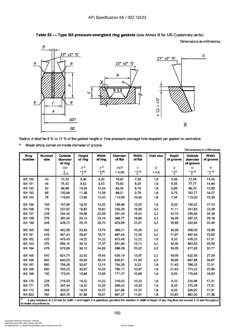
Copyright American Petroleum Institute
Reproduced by IHS under license with API
Not for ResaleNo reproduction or networking permitted without license from IHS
--`,,`,`,-`-`,,`,,`,`,,`---
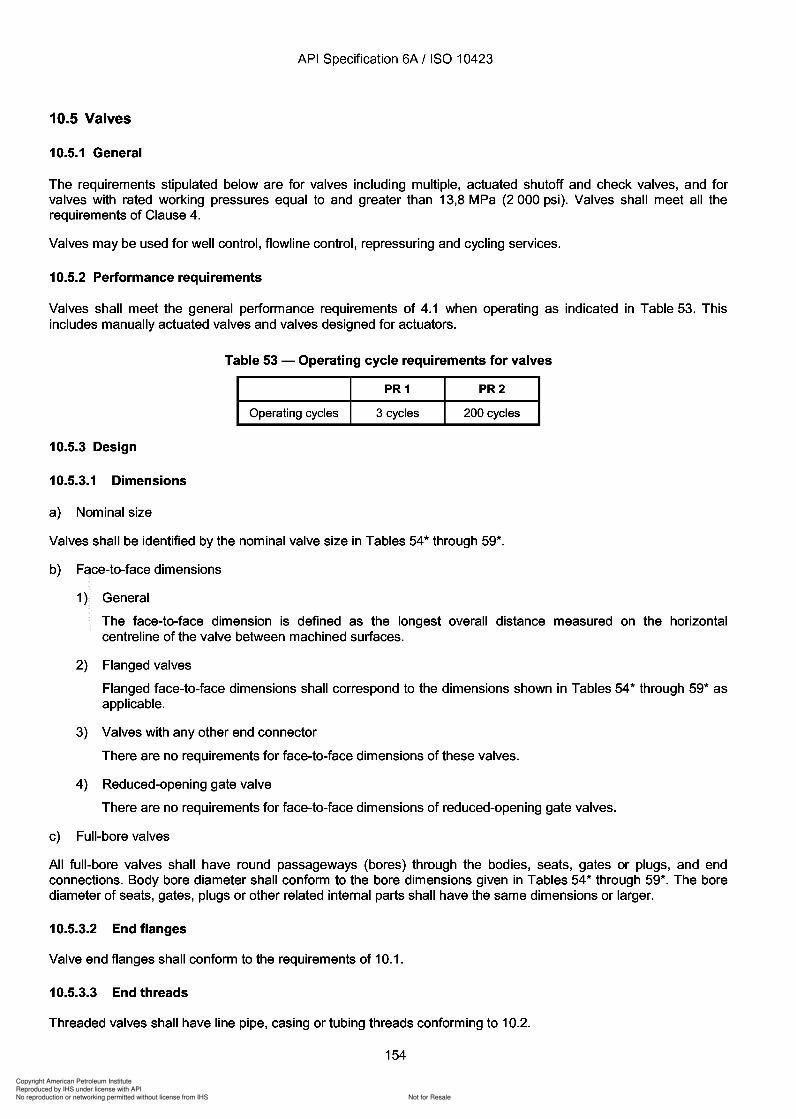
Copyright American Petroleum Institute
Reproduced by IHS under license with API
Not for ResaleNo reproduction or networking permitted without license from IHS
--`,,`,`,-`-`,,`,,`,`,,`---
Copyright American Petroleum Institute
Reproduced by IHS under license with API
Not for ResaleNo reproduction or networking permitted without license from IHS
--`,,`,`,-`-`,,`,,`,`,,`---
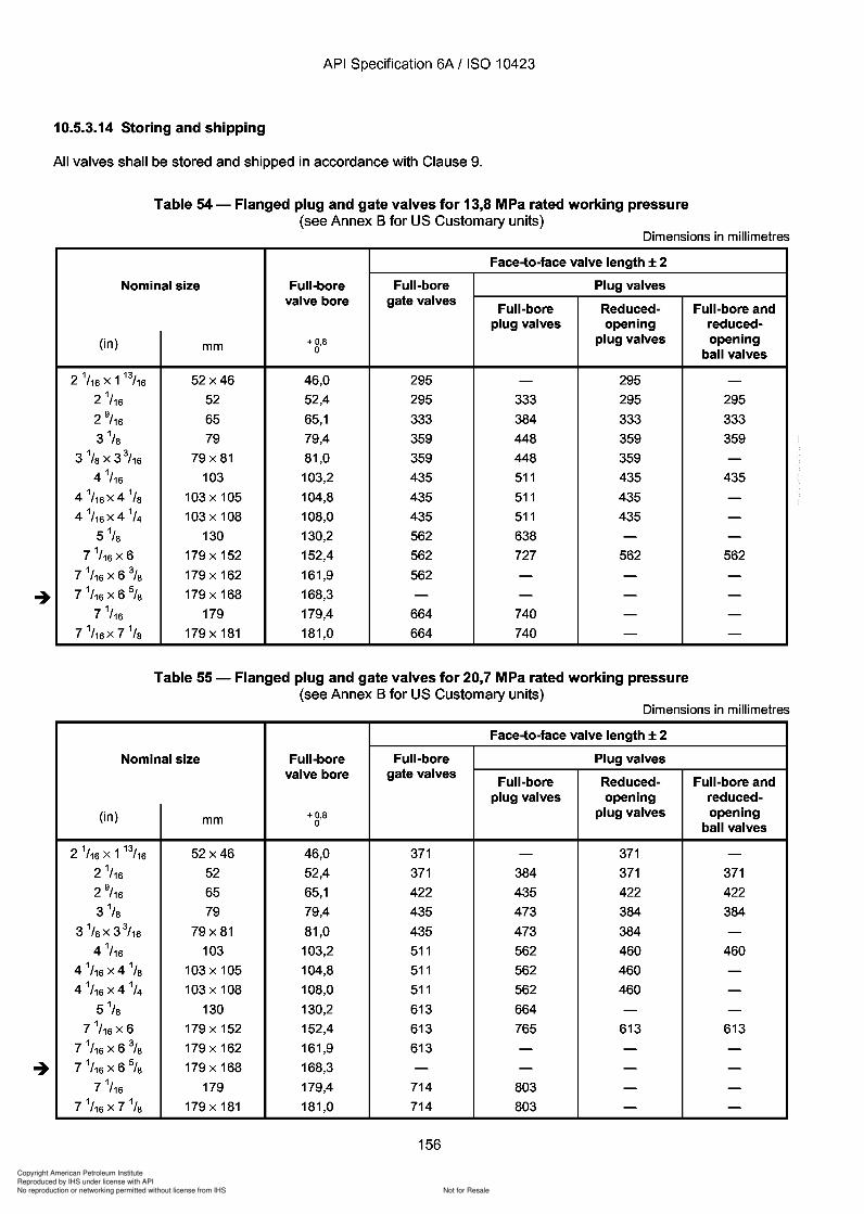
Copyright American Petroleum Institute
Reproduced by IHS under license with API
Not for ResaleNo reproduction or networking permitted without license from IHS
--`,,`,`,-`-`,,`,,`,`,,`---
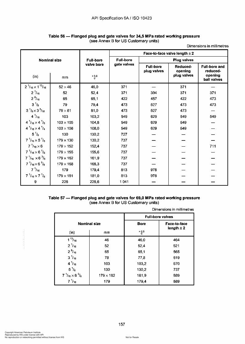
Copyright American Petroleum Institute
Reproduced by IHS under license with API
Not for ResaleNo reproduction or networking permitted without license from IHS
--`,,`,`,-`-`,,`,,`,`,,`---
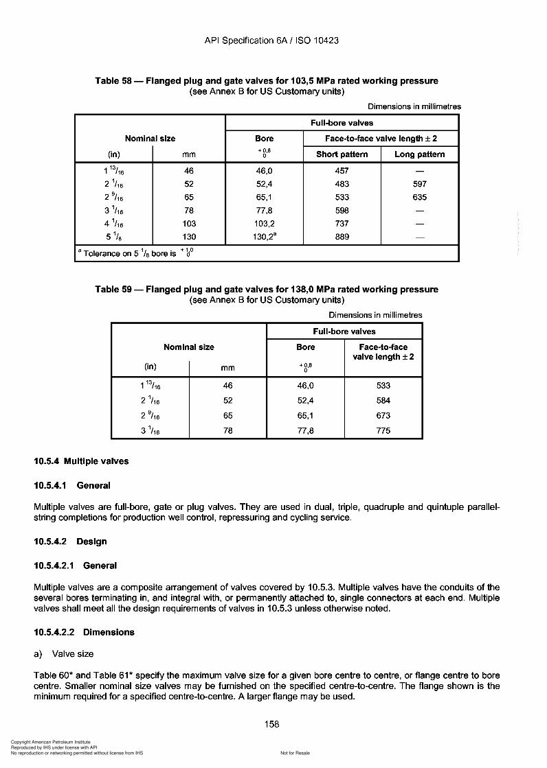
Copyright American Petroleum Institute
Reproduced by IHS under license with API
Not for ResaleNo reproduction or networking permitted without license from IHS
--`,,`,`,-`-`,,`,,`,`,,`---
Copyright American Petroleum Institute
Reproduced by IHS under license with API
Not for ResaleNo reproduction or networking permitted without license from IHS
--`,,`,`,-`-`,,`,,`,`,,`---
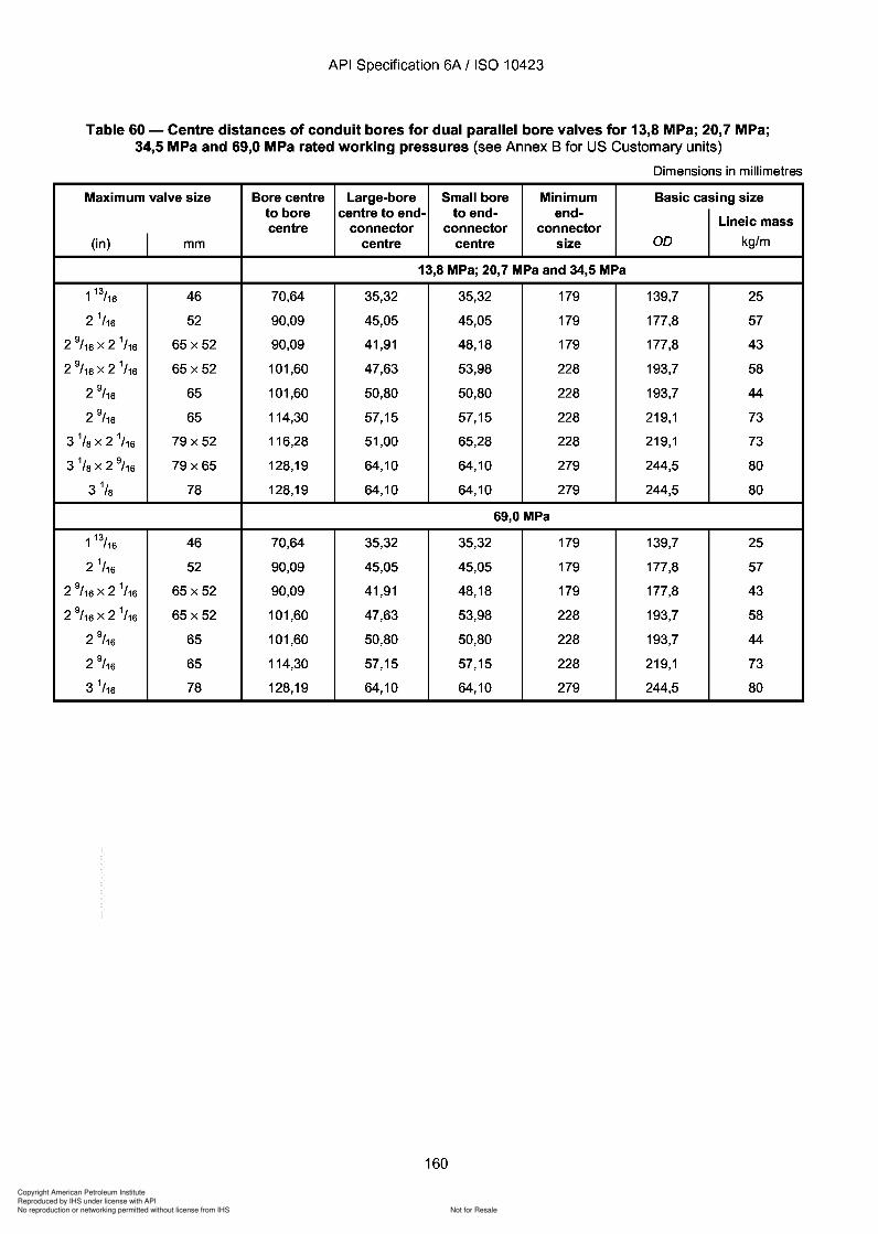
Copyright American Petroleum Institute
Reproduced by IHS under license with API
Not for ResaleNo reproduction or networking permitted without license from IHS
--`,,`,`,-`-`,,`,,`,`,,`---
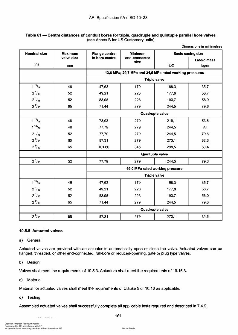
Copyright American Petroleum Institute
Reproduced by IHS under license with API
Not for ResaleNo reproduction or networking permitted without license from IHS
--`,,`,`,-`-`,,`,,`,`,,`---
API Specification 6A / ISO 10423
Table 61 - Centre distances of conduit bores for triple, quadruple and quintuple parallel bore valves(see Annex B for US Customary units)
Dimensions in millimetres
Nominal size Maximum Flange centre Minimum Basic casing sizevalve size to bore centre end-connector
Lineic masssize(in) mm 00 kg/m
13,8 MPa; 20,7 MPa and 34,5 MPa rated working pressures
Triple valve
113/16 46 47,63 179 168,3 35,7
2 1/16 52 49,21 228 177,8 38,7
2 1/16 52 53,98 228 193,7 58,0
2 9/ 16 65 71,44 279 244,5 79,6
Quadruple valve
113/16 46 73,03 279 219,1 53,6
113/16 46 77,79 279 244,5 All
2 1/16 52 77,79 279 244,5 79,6
2 9/ 16 65 87,31 279 273,1 82,6
2 9/ 16 65 101,60 346 298,5 80,4
Quintuple valve
2 1/16 52 77,79 279 244,5 79,6
69,0 MPa rated working pressure
Triple valve
113/16 46 47,63 179 168,3 35,7
2 1/16 52 49,21 228 177,8 38,7
2 1/16 52 53,98 228 193,7 58,0
2 9/ 16 65 71,44 279 244,5 79,6
Quadruple valve
2 9/ 16 65 87,31 279 273,1 82,6
10.5.5 Actuated valves
a) General
Actuated valves are provided with an actuator to automatically open or close the valve. Actuated valves can beflanged, threaded, or other end-connected, full-bore or reduced-opening, gate or plug type valves.
b) Design
Valves shall meet the requirements of 10.5.3. Actuators shall meet the requirements of 10.16.3.
c) Material
Material for actuated valves shall meet the requirements of Clause 5 or 10.16 as applicable.
d) Testing
Assembled actuated valves shall successfully complete all applicable tests required and described in 7.4.9.
161
API Specification 6A / ISO 10423
Table 61 - Centre distances of conduit bores for triple, quadruple and quintuple parallel bore valves (see Annex B for US Customary units)
Dimensions in millimetres
Nominal size Maximum Flange centre Minimum Basic casing size valve size to bore centre end-connector
Lineic mass size (in) mm 00 kg/m
13,8 MPa; 20,7 MPa and 34,5 MPa rated working pressures
Triple valve
113
/16 46 47,63 179 168,3 35,7
21/16 52 49,21 228 177,8 38,7
2 1/16 52 53,98 228 193,7 58,0
2 9/ 16 65 71,44 279 244,5 79,6
Quadruple valve
113
/16 46 73,03 279 219,1 53,6
113
/16 46 77,79 279 244,5 All
21/16 52 77,79 279 244,5 79,6
2 9/ 16 65 87,31 279 273,1 82,6
2 9/ 16 65 101,60 346 298,5 80,4
Quintuple valve
21/16 52 77,79 279 244,5 79,6
69,0 MPa rated working pressure
Triple valve
113
/16 46 47,63 179 168,3 35,7
21/16 52 49,21 228 177,8 38,7
21/16 52 53,98 228 193,7 58,0
2 9/ 16 65 71,44 279 244,5 79,6
Quadruple valve
2 9/ 16 65 87,31 279 273,1 82,6
10.5.5 Actuated valves
a) General
Actuated valves are provided with an actuator to automatically open or close the valve. Actuated valves can be flanged, threaded, or other end-connected, full-bore or reduced-opening, gate or plug type valves.
b) Design
Valves shall meet the requirements of 10.5.3. Actuators shall meet the requirements of 10.16.3.
c) Material
Material for actuated valves shall meet the requirements of Clause 5 or 10.16 as applicable.
d) Testing
Assembled actuated valves shall successfully complete all applicable tests required and described in 7.4.9.
161
Copyright American Petroleum Institute
Reproduced by IHS under license with API
Not for ResaleNo reproduction or networking permitted without license from IHS
--`,,`,`,-`-`,,`,,`,`,,`---
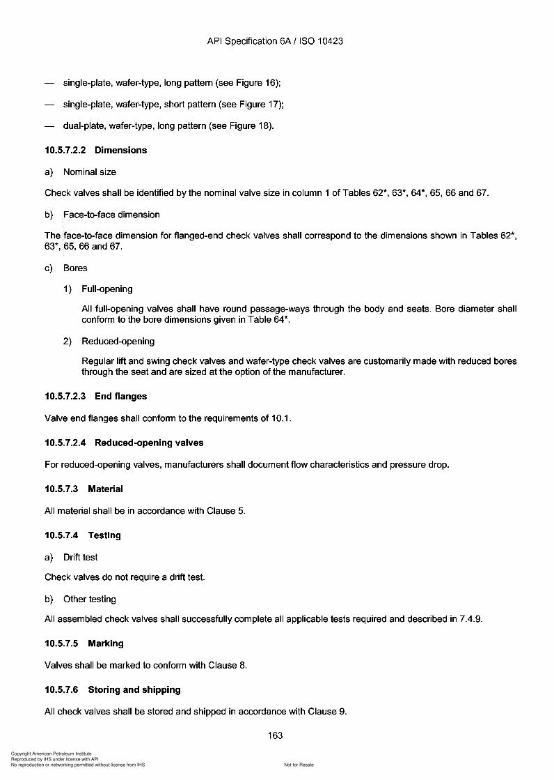
Copyright American Petroleum Institute
Reproduced by IHS under license with API
Not for ResaleNo reproduction or networking permitted without license from IHS
--`,,`,`,-`-`,,`,,`,`,,`---
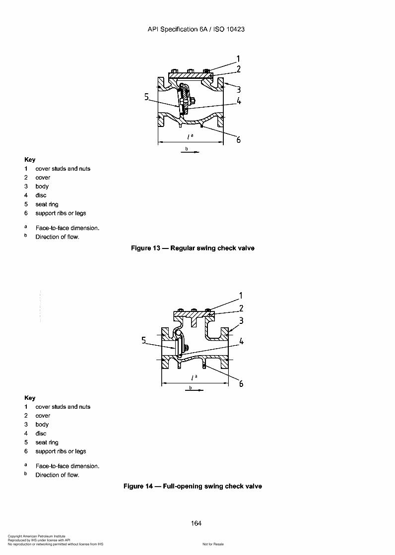
Copyright American Petroleum Institute
Reproduced by IHS under license with API
Not for ResaleNo reproduction or networking permitted without license from IHS
--`,,`,`,-`-`,,`,,`,`,,`---
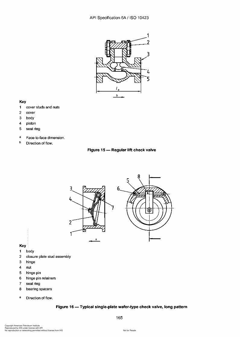
Copyright American Petroleum Institute
Reproduced by IHS under license with API
Not for ResaleNo reproduction or networking permitted without license from IHS
--`,,`,`,-`-`,,`,,`,`,,`---
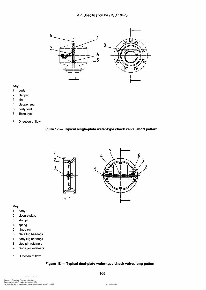
3
Copyright American Petroleum Institute
Reproduced by IHS under license with API
Not for ResaleNo reproduction or networking permitted without license from IHS
--`,,`,`,-`-`,,`,,`,`,,`---
API Specification 6A / ISO 10423
Key
1 body
2 clapper
3 pin
4 clapper seal
5 body seat
6 lifting eye
a Direction of flow.
6
2
a---
3
Figure 17 - Typical single-plate wafer-type check valve, short pattern
Key
1 body
2 closure plate
3 stop pin
4 spring
5 hinge pin
6 plate lug bearings
7 body lug bearings
8 stop pin retainers
9 hinge pin retainers
a Direction of flow.
a-
5 !-
Figure 18 - Typical dual-plate wafer-type check valve, long pattern
166
Key
1 body
2 clapper
3 pin
4 clapper seal
5 body seat
6 lifting eye
a Direction of flow.
6
2
API Specification 6A / ISO 10423
1
4
:::-:G--~r----5
a ---
3
Figure 17 - Typical single-plate wafer-type check valve, short pattern
Key
1 body
2 closure plate
3 stop pin
4 spring
5 hinge pin
6 plate lug bearings
7 body lug bearings
8 stop pin retainers
9 hinge pin retainers
a Direction of flow.
1 2
3 ~-......
a -
5 !-
Figure 18 - Typical dual-plate wafer-type check valve, long pattern
166
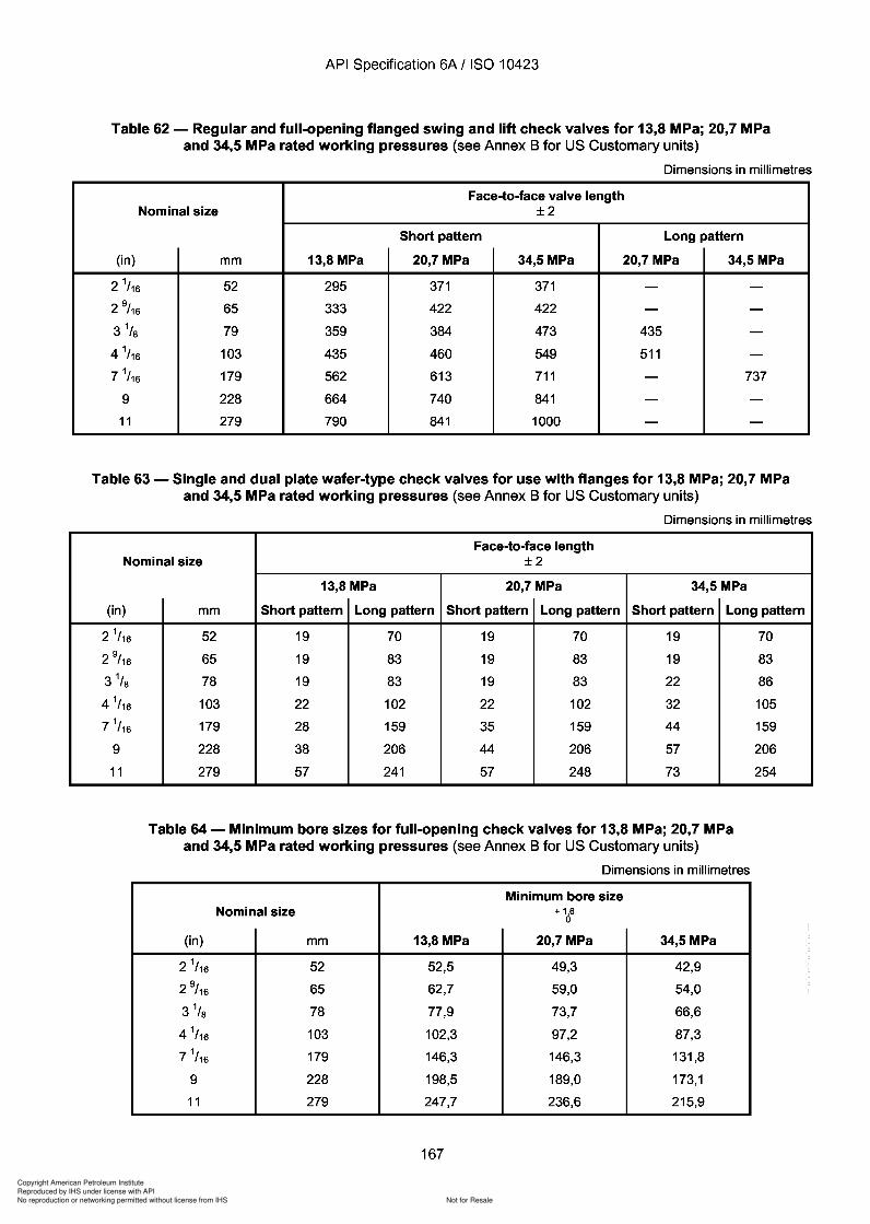
Copyright American Petroleum Institute
Reproduced by IHS under license with API
Not for ResaleNo reproduction or networking permitted without license from IHS
--`,,`,`,-`-`,,`,,`,`,,`---
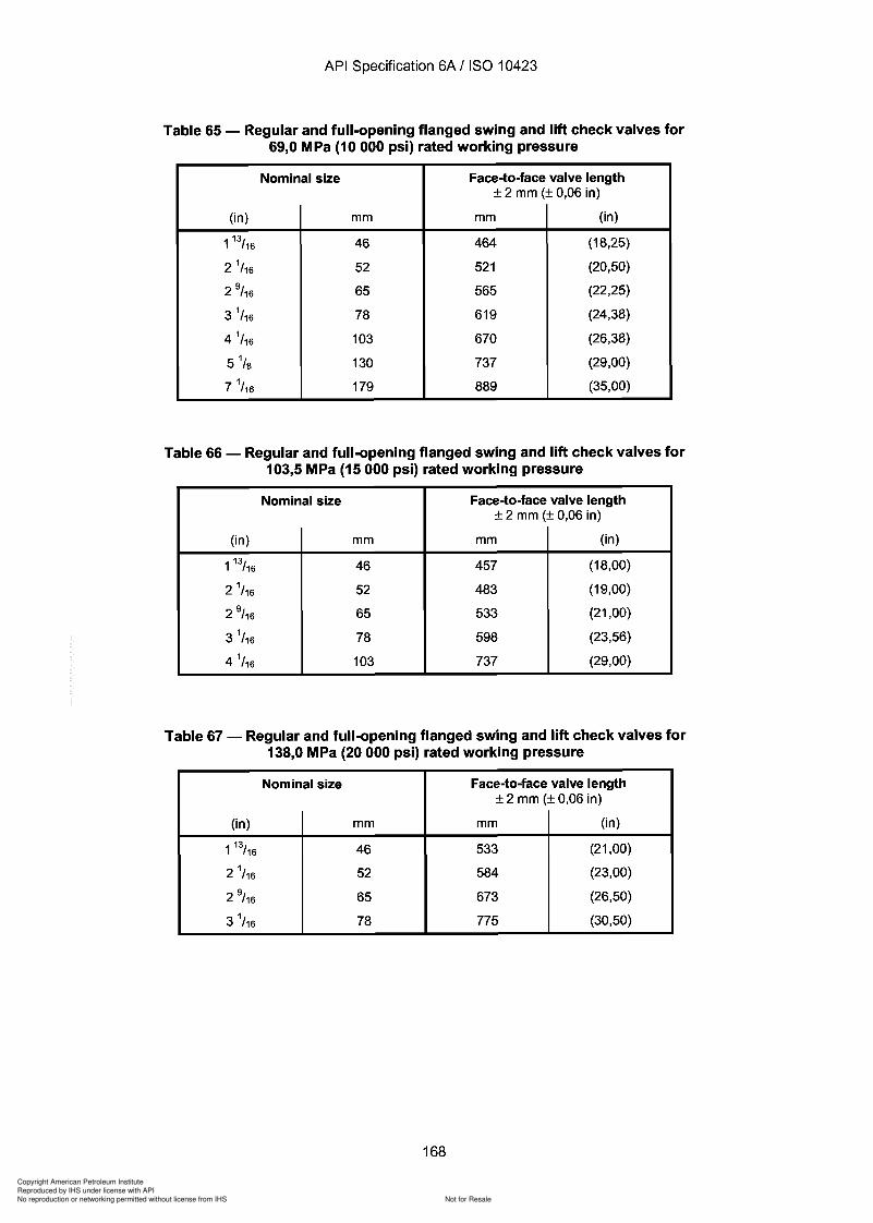
1 46
2 52
2 65
3 78
2 0,06
533
584
673
775
46
52
65
78
103
130
179
0,06
464
52 1
565
61 9
670
737
889
Copyright American Petroleum Institute
Reproduced by IHS under license with API
Not for ResaleNo reproduction or networking permitted without license from IHS
--`,,`,`,-`-`,,`,,`,`,,`---
Copyright American Petroleum Institute
Reproduced by IHS under license with API
Not for ResaleNo reproduction or networking permitted without license from IHS
--`,,`,`,-`-`,,`,,`,`,,`---
Copyright American Petroleum Institute
Reproduced by IHS under license with API
Not for ResaleNo reproduction or networking permitted without license from IHS
--`,,`,`,-`-`,,`,,`,`,,`---
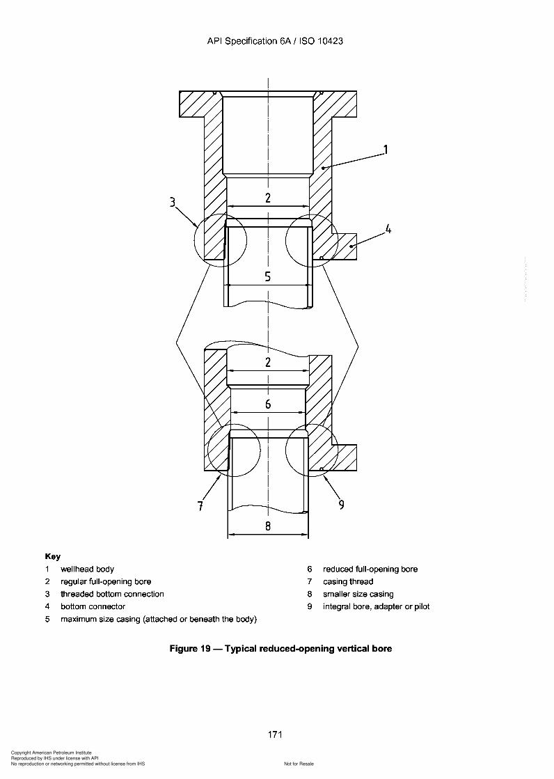
3
Copyright American Petroleum Institute
Reproduced by IHS under license with API
Not for ResaleNo reproduction or networking permitted without license from IHS
--`,,`,`,-`-`,,`,,`,`,,`---
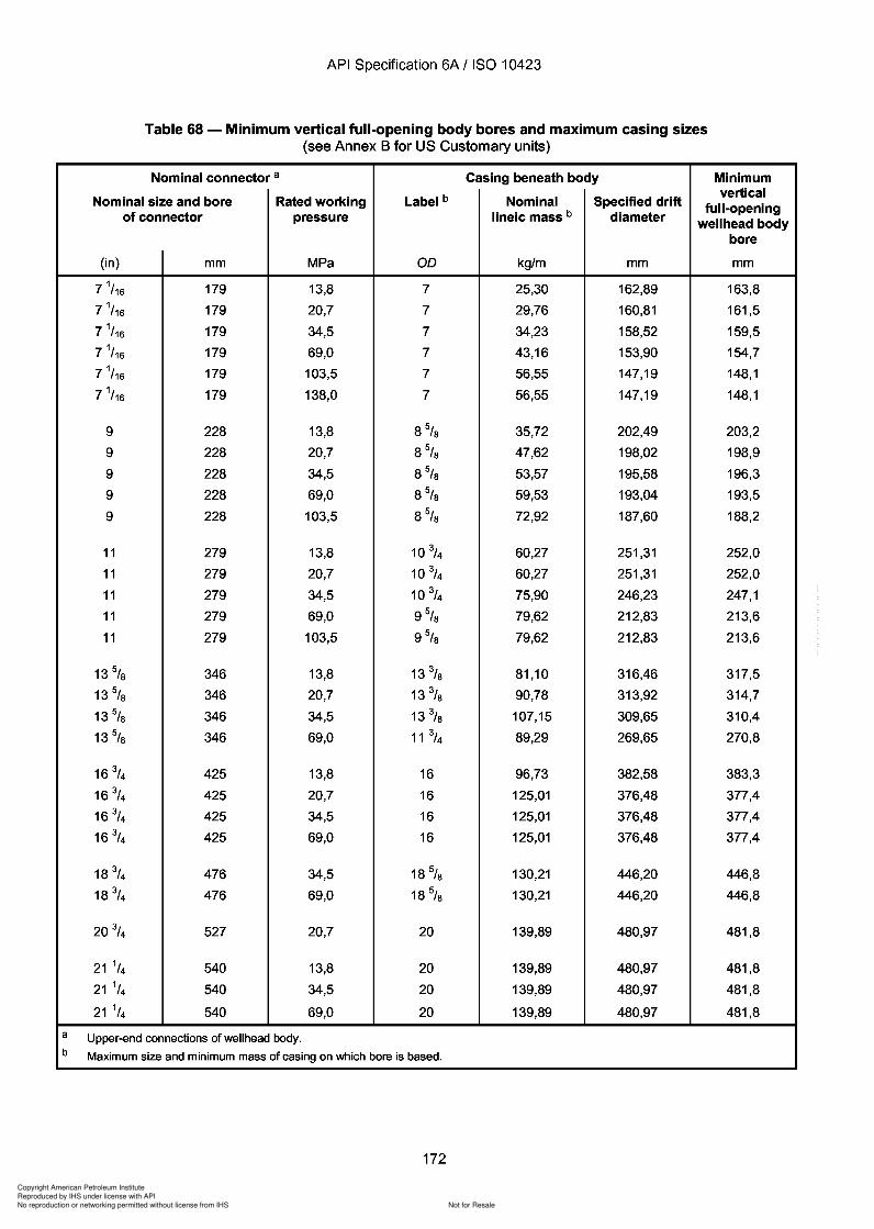
Copyright American Petroleum Institute
Reproduced by IHS under license with API
Not for ResaleNo reproduction or networking permitted without license from IHS
--`,,`,`,-`-`,,`,,`,`,,`---
Copyright American Petroleum Institute
Reproduced by IHS under license with API
Not for ResaleNo reproduction or networking permitted without license from IHS
--`,,`,`,-`-`,,`,,`,`,,`---
Copyright American Petroleum Institute
Reproduced by IHS under license with API
Not for ResaleNo reproduction or networking permitted without license from IHS
--`,,`,`,-`-`,,`,,`,`,,`---
Copyright American Petroleum Institute
Reproduced by IHS under license with API
Not for ResaleNo reproduction or networking permitted without license from IHS
--`,,`,`,-`-`,,`,,`,`,,`---
API Specification 6A / ISO 10423
d) Group 4
Same as Group 3. Additionally, minimum retention load capacity of the hanger's retention feature shall be equal tothe force generated by the working pressure on the annular area.
e) Group 5
Same as Group 3. Additionally:
minimum retention load capacity of the hanger's retention feature shall be equal to the force generated by theworking pressure acting on the full area of the largest hanger seal;
back-pressure valve preparations shall be capable of holding rated working pressure from below.
The load and pressure ratings for casing and tubing hangers may be a function of the tubular grade of material andwall section as well as the wellhead equipment in which it is installed. Manufacturers shall be responsible forsupplying information about the load/pressure ratings of such hangers.
Field test pressures may be different from the rated working pressure of a hanger due to casing-collapserestrictions or load-shoulder limits.
Nothing in this subclause shall be interpreted to be a requirement of a wrap-around seal type tubing hanger.
10.7.2 Specific performance requirements
10.7.2.1 Slip hangers
a) Load capacity
The load capacity for slip hangers shall be as specified in Table 69.
b) Temperature rating
The temperature rating of slip hangers shall be in accordance with 4.2.2. Choosing the temperature rating is theultimate responsibility of the user. In making these selections, the user should consider the temperature theequipment will experience in drilling and/or production service.
NOTE The temperature rating of the slip hanger may be less than the temperature rating of the wellhead and/or tree.
c) Performance requirements for Group 1 slip hangers
Group 1 slip hangers shall meet the general requirements of 4.1, except they are not required to have pressureintegrity.
d) Performance requirements for Group 2 slip hangers
Group 2 slip hangers shall meet the general requirements of 4.1. They shall seal maximum rated pressure in onedirection across the annular seal at the rated load capacity for that pressure.
e) Performance requirements for Group 3 slip hangers
Group 3 slip hangers shall meet the general requirements of 4.1. They shall seal maximum rated pressure aboveand below the annular seal at the rated load capacity for that pressure. If a cross-over pack-off is included on thehanger, then it shall hold the higher rated working pressure from above. If downhole lines are included they shallhold the rated working pressure of the hanger. Any effect of the pressure load shall be included in the load rating.
175
API Specification 6A / ISO 10423
d) Group 4
Same as Group 3. Additionally, minimum retention load capacity of the hanger's retention feature shall be equal to the force generated by the working pressure on the annular area.
e) Group 5
Same as Group 3. Additionally:
minimum retention load capacity of the hanger's retention feature shall be equal to the force generated by the working pressure acting on the full area of the largest hanger seal;
back-pressure valve preparations shall be capable of holding rated working pressure from below.
The load and pressure ratings for casing and tubing hangers may be a function of the tubular grade of material and wall section as well as the wellhead equipment in which it is installed. Manufacturers shall be responsible for supplying information about the load/pressure ratings of such hangers.
Field test pressures may be different from the rated working pressure of a hanger due to casing-collapse restrictions or load-shoulder limits.
Nothing in this subclause shall be interpreted to be a requirement of a wrap-around seal type tubing hanger.
10.7.2 Specific performance requirements
10.7.2.1 Slip hangers
a) Load capacity
The load capacity for slip hangers shall be as specified in Table 69.
b) Temperature rating
The temperature rating of slip hangers shall be in accordance with 4.2.2. Choosing the temperature rating is the ultimate responsibility of the user. In making these selections, the user should consider the temperature the equipment will experience in drilling and/or production service.
NOTE The temperature rating of the slip hanger may be less than the temperature rating of the wellhead and/or tree.
c) Performance requirements for Group 1 slip hangers
Group 1 slip hangers shall meet the general requirements of 4.1, except they are not required to have pressure integrity.
d) Performance requirements for Group 2 slip hangers
Group 2 slip hangers shall meet the general requirements of 4.1. They shall seal maximum rated pressure in one direction across the annular seal at the rated load capacity for that pressure.
e) Performance requirements for Group 3 slip hangers
Group 3 slip hangers shall meet the general requirements of 4.1. They shall seal maximum rated pressure above and below the annular seal at the rated load capacity for that pressure. If a cross-over pack-off is included on the hanger, then it shall hold the higher rated working pressure from above. If downhole lines are included they shall hold the rated working pressure of the hanger. Any effect of the pressure load shall be included in the load rating.
175
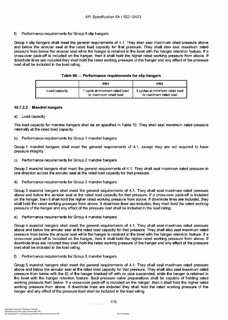
Copyright American Petroleum Institute
Reproduced by IHS under license with API
Not for ResaleNo reproduction or networking permitted without license from IHS
--`,,`,`,-`-`,,`,,`,`,,`---
API Specification 6A / ISO 10423
f) Performance requirements for Group 4 slip hangers
Group 4 slip hangers shall meet the general requirements of 4.1. They shall seal maximum rated pressure aboveand below the annular seal at the rated load capacity for that pressure. They shall also seal maximum ratedpressure from below the annular seal while the hanger is retained in the bowl with the hanger retention feature. If across-over pack-off is included on the hanger, then it shall hold the higher rated working pressure from above. Ifdownhole lines are included they shall hold the rated working pressure of the hanger and any effect of the pressureload shall be included in the load rating.
Table 69 - Performance requirements for slip hangers
PR1 PR2
Load capacity 1 cycle at minimum rated load 3 cycles at minimum rated loadto maximum rated load to maximum rated load
10.7.2.2 Mandrel hangers
a) Load capacity
The load capacity for mandrel hangers shall be as specified in Table 70. They shall seal maximum rated pressureinternally at the rated load capacity.
b) Performance requirements for Group 1 mandrel hangers
Group 1 mandrel hangers shall meet the general requirements of 4.1, except they are not required to havepressure integrity.
c) Performance requirements for Group 2 mandrel hangers
Group 2 mandrel hangers shall meet the general requirements of 4.1. They shall seal maximum rated pressure inone direction across the annular seal at the rated load capacity for that pressure.
d) Performance requirements for Group 3 mandrel hangers
Group 3 mandrel hangers shall meet the general requirements of 4.1. They shall seal maximum rated pressureabove and below the annular seal at the rated load capacity for that pressure. If a cross-over pack-off is includedon the hanger, then it shall hold the higher rated working pressure from above. If downhole lines are included, theyshall hold the rated working pressure from above. If downhole lines are included, they shall hold the rated workingpressure of the hanger and any effect of the pressure load shall be included in the load rating.
e) Performance requirements for Group 4 mandrel hangers
Group 4 mandrel hangers shall meet the general requirements of 4.1. They shall seal maximum rated pressureabove and below the annular seal at the rated load capacity for that pressure. They shall also seal maximum ratedpressure from below the annular seal while the hanger is retained in the bowl with the hanger retention feature. If across-over pack-off is included on the hanger, then it shall hold the higher rated working pressure from above. Ifdownhole lines are included they shall hold the rated working pressure of the hanger and any effect of the pressureload shall be included in the load rating.
f) Performance requirements for Group 5 mandrel hangers
Group 5 mandrel hangers shall meet the general requirements of 4.1. They shall seal maximum rated pressureabove and below the annular seal at the rated load capacity for that pressure. They shall also seal maximum ratedpressure from below with the ID of the hanger blanked off with no pipe suspended, while the hanger is retained inthe bowl with the hanger retention feature. Back-pressure valve preparations shall be capable of holding ratedworking pressure from below. If a cross-over pack-off is included on the hanger, then it shall hold the higher ratedworking pressure from above. If downhole lines are included they shall hold the rated working pressure of thehanger and any effect of the pressure load shall be included in the load rating.
176
API Specification 6A / ISO 10423
f) Performance requirements for Group 4 slip hangers
Group 4 slip hangers shall meet the general requirements of 4.1. They shall seal maximum rated pressure above and below the annular seal at the rated load capacity for that pressure. They shall also seal maximum rated pressure from below the annular seal while the hanger is retained in the bowl with the hanger retention feature. If a cross-over pack-off is included on the hanger, then it shall hold the higher rated working pressure from above. If downhole lines are included they shall hold the rated working pressure of the hanger and any effect of the pressure load shall be included in the load rating.
Table 69 - Performance requirements for slip hangers
PR1 PR2
Load capacity 1 cycle at minimum rated load 3 cycles at minimum rated load to maximum rated load to maximum rated load
10.7.2.2 Mandrel hangers
a) Load capacity
The load capacity for mandrel hangers shall be as specified in Table 70. They shall seal maximum rated pressure internally at the rated load capacity.
b) Performance requirements for Group 1 mandrel hangers
Group 1 mandrel hangers shall meet the general requirements of 4.1, except they are not required to have pressure integrity.
c) Performance requirements for Group 2 mandrel hangers
Group 2 mandrel hangers shall meet the general requirements of 4.1. They shall seal maximum rated pressure in one direction across the annular seal at the rated load capacity for that pressure.
d) Performance requirements for Group 3 mandrel hangers
Group 3 mandrel hangers shall meet the general requirements of 4.1. They shall seal maximum rated pressure above and below the annular seal at the rated load capacity for that pressure. If a cross-over pack-off is included on the hanger, then it shall hold the higher rated working pressure from above. If downhole lines are included, they shall hold the rated working pressure from above. If downhole lines are included, they shall hold the rated working pressure of the hanger and any effect of the pressure load shall be included in the load rating.
e) Performance requirements for Group 4 mandrel hangers
Group 4 mandrel hangers shall meet the general requirements of 4.1. They shall seal maximum rated pressure above and below the annular seal at the rated load capacity for that pressure. They shall also seal maximum rated pressure from below the annular seal while the hanger is retained in the bowl with the hanger retention feature. If a cross-over pack-off is included on the hanger, then it shall hold the higher rated working pressure from above. If downhole lines are included they shall hold the rated working pressure of the hanger and any effect of the pressure load shall be included in the load rating.
f) Performance requirements for Group 5 mandrel hangers
Group 5 mandrel hangers shall meet the general requirements of 4.1. They shall seal maximum rated pressure above and below the annular seal at the rated load capacity for that pressure. They shall also seal maximum rated pressure from below with the ID of the hanger blanked off with no pipe suspended, while the hanger is retained in the bowl with the hanger retention feature. Back-pressure valve preparations shall be capable of holding rated working pressure from below. If a cross-over pack-off is included on the hanger, then it shall hold the higher rated working pressure from above. If downhole lines are included they shall hold the rated working pressure of the hanger and any effect of the pressure load shall be included in the load rating.
176
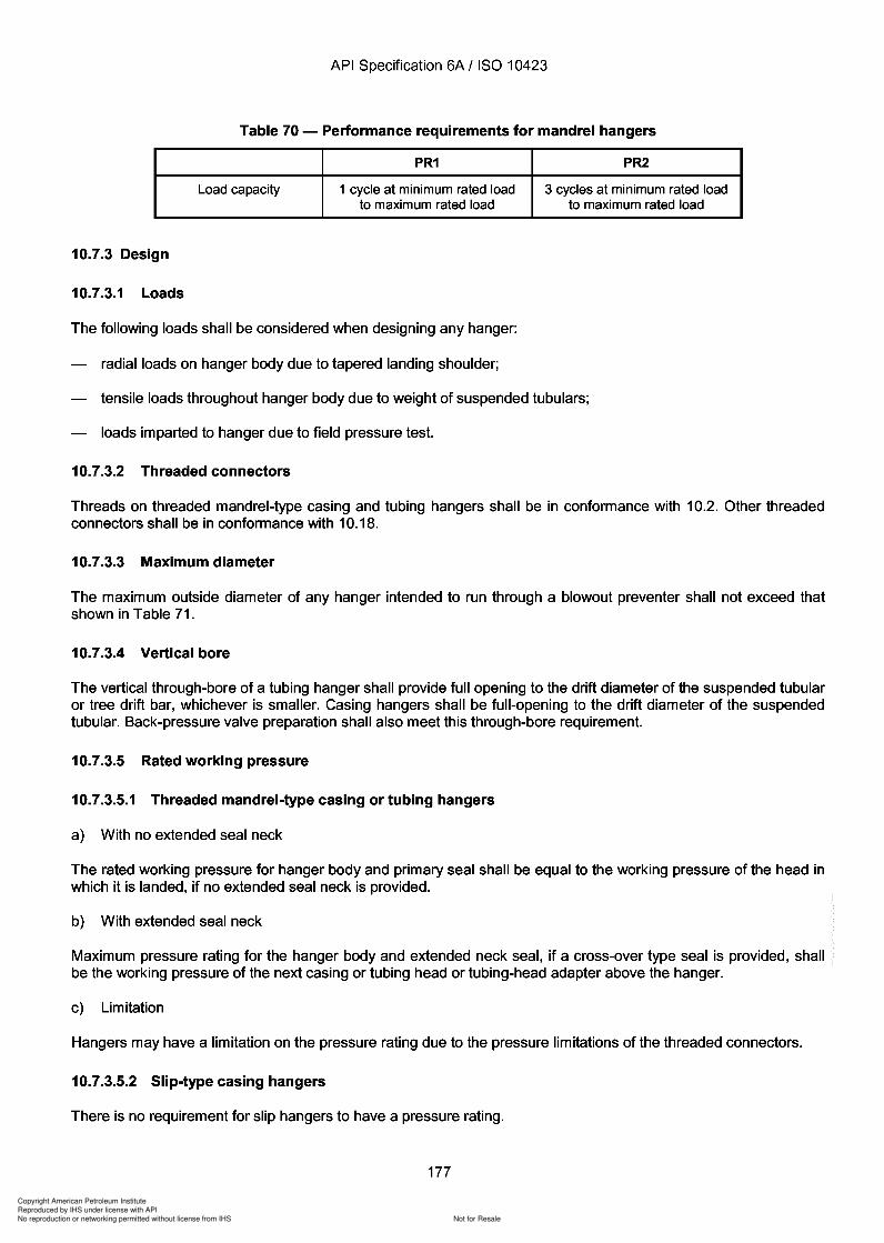
Copyright American Petroleum Institute
Reproduced by IHS under license with API
Not for ResaleNo reproduction or networking permitted without license from IHS
--`,,`,`,-`-`,,`,,`,`,,`---
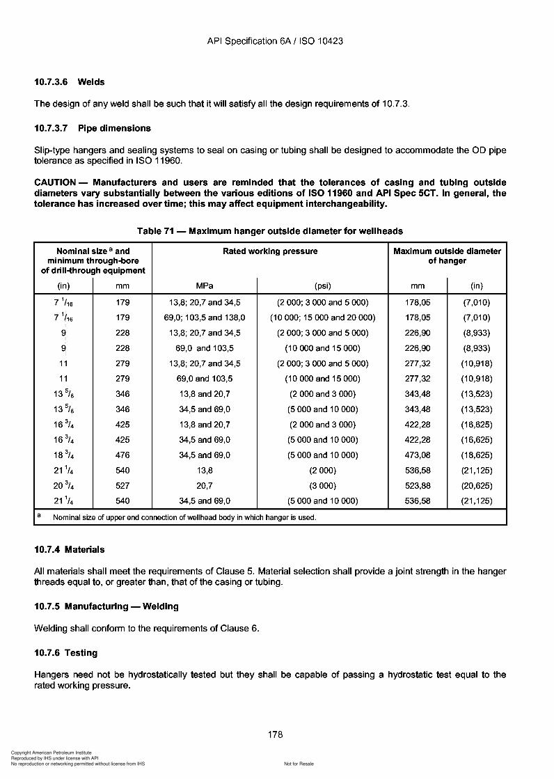
Copyright American Petroleum Institute
Reproduced by IHS under license with API
Not for ResaleNo reproduction or networking permitted without license from IHS
--`,,`,`,-`-`,,`,,`,`,,`---
Copyright American Petroleum Institute
Reproduced by IHS under license with API
Not for ResaleNo reproduction or networking permitted without license from IHS
--`,,`,`,-`-`,,`,,`,`,,`---
API Specification 6A / ISO 10423
10.7.7 Marking
Hangers shall be marked to conform with Clause 8. The slips in a slip hanger shall be sequentially marked if theyare not interchangeable.
10.7.8 Installation
For running and retrieving tools for casing and tubing hangers, see Annex H.
10.7.9 Storing and shipping
Hangers shall be stored and shipped in compliance with Clause 9. The slips of a slip hanger shall be stored andshipped as a set.
10.8 Tubing-head adapters
10.8.1 General
Tubing-head-to-master-valve adapters may be either integral with the master valve as its lower end connector, oran independent piece of equipment. Configurations are dependent upon the completion method to be used. Inaddition to serving as adapters, they may also provide a means to connect and seal the tubing bore(s) to that of themaster valve or to suspend the tubing string(s). Group 1 tubing-head adapters seal the wellbore from the annulus.Group 2 tubing-head adapters seal the wellbore from the annulus and suspend the tubing.
10.8.2 Performance requirements
a) Performance requirements for Group 1 tubing-head adapters
These products shall meet the general requirements of 4.1 and shall be capable of performing as outlined inTable 72.
b) Performance requirements for Group 2 tubing-head adapters
These products shall meet the general requirements of 4.1 and shall be capable of performing as outlined inTable 73.
10.8.3 Design
10.8.3.1 Loads
The following loads shall be considered when designing tubing-head adapters:
hanging and thermal tubular loads on adapters that incorporate hanger mechanisms;
external axial and bending loads consistent with the capabilities of the end connectors.
10.8.3.2 End connectors
a) Lower connector
Flanged or studded lower connectors shall be in conformance with 10.1. Other connectors shall be in conformancewith 10.18.
b) Upper connector
The upper connector of an independent adapter shall be flanged or studded, in conformance with 10.1, orthreaded, in conformance with 10.2, or have an other-end connector in conformance with 10.18 or hub end
179
API Specification 6A / ISO 10423
10.7.7 Marking
Hangers shall be marked to conform with Clause 8. The slips in a slip hanger shall be sequentially marked if they are not interchangeable.
10.7.8 Installation
For running and retrieving tools for casing and tubing hangers, see Annex H.
10.7.9 Storing and shipping
Hangers shall be stored and shipped in compliance with Clause 9. The slips of a slip hanger shall be stored and shipped as a set.
10.8 Tubing-head adapters
10.8.1 General
Tubing-head-to-master-valve adapters may be either integral with the master valve as its lower end connector, or an independent piece of equipment. Configurations are dependent upon the completion method to be used. In addition to serving as adapters, they may also provide a means to connect and seal the tubing bore(s) to that of the master valve or to suspend the tubing string(s). Group 1 tubing-head adapters seal the wellbore from the annulus. Group 2 tubing-head adapters seal the wellbore from the annulus and suspend the tubing.
10.8.2 Performance requirements
a) Performance requirements for Group 1 tubing-head adapters
These products shall meet the general requirements of 4.1 and shall be capable of performing as outlined in Table 72.
b) Performance requirements for Group 2 tubing-head adapters
These products shall meet the general requirements of 4.1 and shall be capable of performing as outlined in Table 73.
10.8.3 Design
10.8.3.1 Loads
The following loads shall be considered when designing tubing-head adapters:
hanging and thermal tubular loads on adapters that incorporate hanger mechanisms;
external axial and bending loads consistent with the capabilities of the end connectors.
10.8.3.2 End connectors
a) Lower connector
Flanged or studded lower connectors shall be in conformance with 10.1. Other connectors shall be in conformance with 10.18.
b) Upper connector
The upper connector of an independent adapter shall be flanged or studded, in conformance with 10.1, or threaded, in conformance with 10.2, or have an other-end connector in conformance with 10.18 or hub end
179
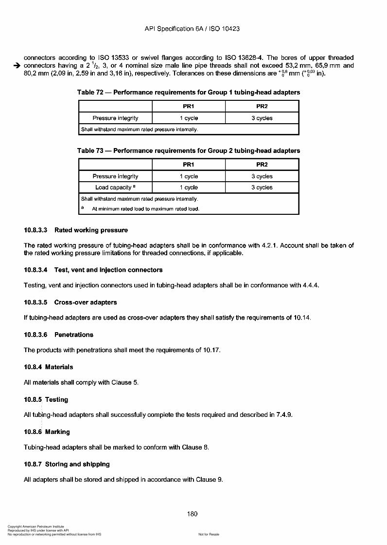
Copyright American Petroleum Institute
Reproduced by IHS under license with API
Not for ResaleNo reproduction or networking permitted without license from IHS
--`,,`,`,-`-`,,`,,`,`,,`---
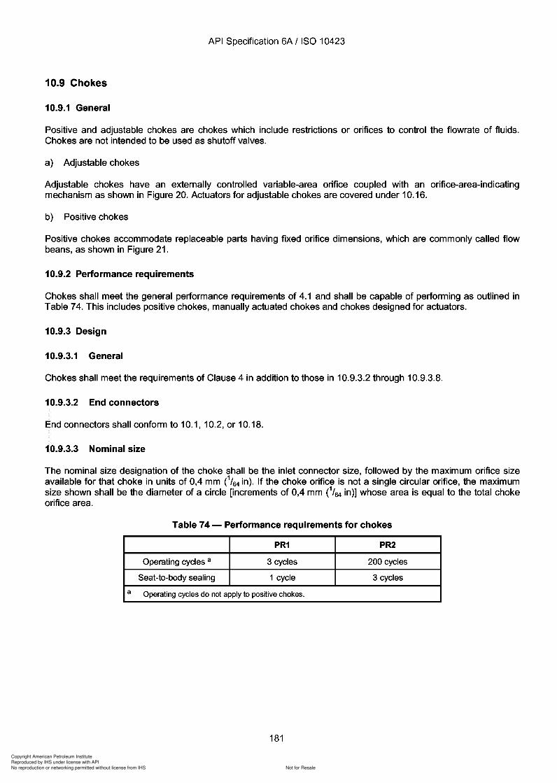
Copyright American Petroleum Institute
Reproduced by IHS under license with API
Not for ResaleNo reproduction or networking permitted without license from IHS
--`,,`,`,-`-`,,`,,`,`,,`---
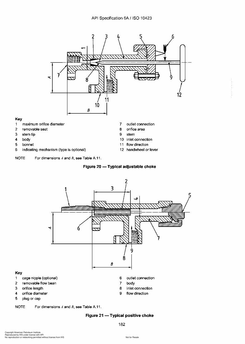
Copyright American Petroleum Institute
Reproduced by IHS under license with API
Not for ResaleNo reproduction or networking permitted without license from IHS
--`,,`,`,-`-`,,`,,`,`,,`---
Copyright American Petroleum Institute
Reproduced by IHS under license with API
Not for ResaleNo reproduction or networking permitted without license from IHS
--`,,`,`,-`-`,,`,,`,`,,`---
API Specification 6A / ISO 10423
10.9.3.4 Rated working pressure
a) End connectors with equal rated working pressures
For chokes having end connectors of the same rated working pressure, the rated working pressure of the chokeshall be the rated working pressure of the end connectors.
b) End connectors with different rated working pressures
For chokes having an upstream end connector of higher rated working pressure than the downstream endconnector, the choke shall have a two-part rated working pressure consisting of the rated working pressure of theupstream end connector and the rated working pressure of the downstream end connector [e.g.20,7 MPa x 13,8 MPa (3 000 psi x 2000 psi)].
10.9.3.5 Flow design
Chokes shall be designed to direct flow away from the bonnet of adjustable chokes and the cap, or blanking plug,of positive chokes.
10.9.3.6 Vent requirement
All chokes shall be designed to vent trapped pressure prior to releasing the body-to-bonnet connector onadjustable chokes or the body-to-cap connector on positive chokes.
10.9.3.7 Flow beans for positive chokes
Flow beans are defined as the replaceable orifice parts of positive chokes.
The orifice size of any individual production flow bean and the increment between sizes are optional with themanufacturer but shall be specified in diameter increments of 0,4 mm C/64 in).
-+10.9.3.8 Adjustable choke indicating mechanism
Adjustable chokes shall be equipped with a visible orifice-area-indicating mechanism to define the orifice area atany adjusted choke setting throughout its operating range. This mechanism shall be calibrated to indicatediameters of circular orifices having areas equivalent to the minimum flow areas at any adjustable choke setting.These markings shall be in diametrical increments of either 0,8 mm C/32 in) or 0,4 mm C/64 in). Actuated chokes arenot required to be equipped with indicating mechanisms.
10.9.4 Material
a) Bodies, bonnets, plugs or caps, and end connectors
Materials for these parts shall comply with Clause 5.
b) Other parts
Material for all other parts shall meet the requirements of Clause 5 or 10.16 as applicable. Additionally, specialcorrosion- and abrasion-resistant materials, coatings or overlays shall be used for adjustable choke stem tips andpositive choke flow beans.
10.9.5 Testing
Assembled chokes shall successfully complete the tests required and described in 7.4.9.
183
-+
API Specification 6A I ISO 10423
10.9.3.4 Rated working pressure
a) End connectors with equal rated working pressures
For chokes having end connectors of the same rated working pressure, the rated working pressure of the choke shall be the rated working pressure of the end connectors.
b) End connectors with different rated working pressures
For chokes having an upstream end connector of higher rated working pressure than the downstream end connector, the choke shall have a two-part rated working pressure consisting of the rated working pressure of the upstream end connector and the rated working pressure of the downstream end connector [e.g. 20,7 MPa x 13,8 MPa (3 000 psi x 2000 psi)].
10.9.3.5 Flow design
Chokes shall be designed to direct flow away from the bonnet of adjustable chokes and the cap, or blanking plug, of positive chokes.
10.9.3.6 Vent requirement
All chokes shall be designed to vent trapped pressure prior to releasing the bOdy-to-bonnet connector on adjustable chokes or the body-to-cap connector on positive chokes.
10.9.3.7 Flow beans for positive chokes
Flow beans are defined as the replaceable orifice parts of positive chokes.
The orifice size of any individual production flow bean and the increment between sizes are optional with the manufacturer but shall be specified in diameter increments of 0,4 mm CI64 in).
10.9.3.8 Adjustable choke indicating mechanism
Adjustable chokes shall be equipped with a visible orifice-area-indicating mechanism to define the orifice area at any adjusted choke setting throughout its operating range. This mechanism shall be calibrated to indicate diameters of circular orifices having areas equivalent to the minimum flow areas at any adjustable choke setting. These markings shall be in diametrical increments of either 0,8 mm CI32 in) or 0,4 mm CI64 in). Actuated chokes are not required to be equipped with indicating mechanisms.
10.9.4 Material
a) Bodies, bonnets, plugs or caps, and end connectors
Materials for these parts shall comply with Clause 5.
b) Other parts
Material for all other parts shall meet the requirements of Clause 5 or 10.16 as applicable. Additionally, special corrosion- and abrasion-resistant materials, coatings or overlays shall be used for adjustable choke stem tips and positive choke flow beans.
10.9.5 Testing
Assembled chokes shall successfully complete the tests required and described in 7.4.9.
183
Copyright American Petroleum Institute
Reproduced by IHS under license with API
Not for ResaleNo reproduction or networking permitted without license from IHS
--`,,`,`,-`-`,,`,,`,`,,`---
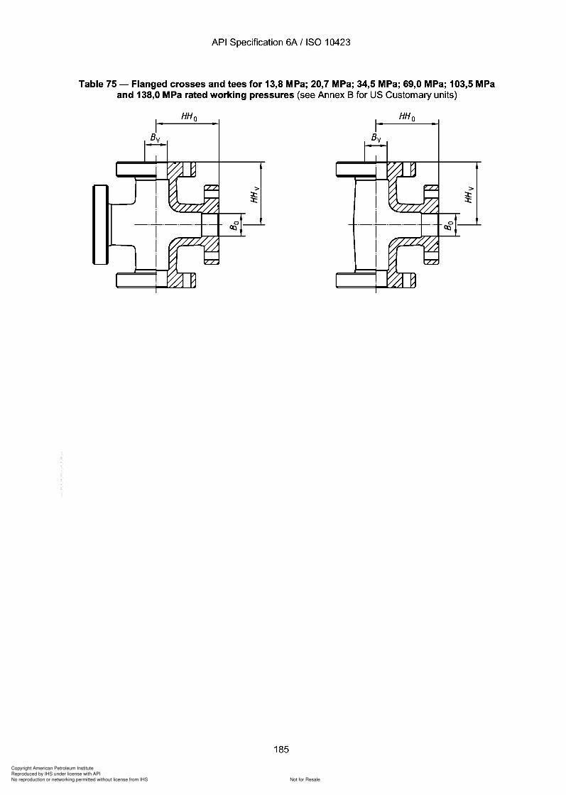
Copyright American Petroleum Institute
Reproduced by IHS under license with API
Not for ResaleNo reproduction or networking permitted without license from IHS
--`,,`,`,-`-`,,`,,`,`,,`---
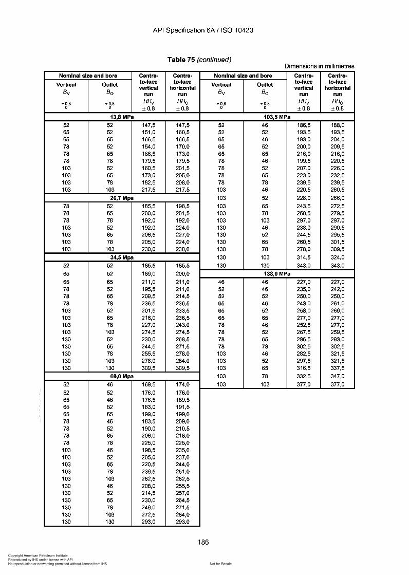
Copyright American Petroleum Institute
Reproduced by IHS under license with API
Not for ResaleNo reproduction or networking permitted without license from IHS
--`,,`,`,-`-`,,`,,`,`,,`---
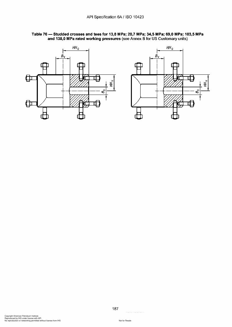
Copyright American Petroleum Institute
Reproduced by IHS under license with API
Not for ResaleNo reproduction or networking permitted without license from IHS
--`,,`,`,-`-`,,`,,`,`,,`---
API Specification 6A / ISO 10423
Table 76 - Studded crosses and tees for 13,8 MPa; 20,7 MPa; 34,5 MPa; 69,0 MPa; 103,5 MPaand 138,0 MPa rated working pressures (see Annex B for US Customary units)
HH o
187
HH o
API Specification 6A / ISO 10423
Table 76 - Studded crosses and tees for 13,8 MPa; 20,7 MPa; 34,5 MPa; 69,0 MPa; 103,5 MPa and 138,0 MPa rated working pressures (see Annex B for US Customary units)
HHo HHo
>
JL-L.L.L..L.L..'-t-----+ ~
187

Copyright American Petroleum Institute
Reproduced by IHS under license with API
Not for ResaleNo reproduction or networking permitted without license from IHS
--`,,`,`,-`-`,,`,,`,`,,`---
API Specification 6A / ISO 10423
Table 76 (continued)Dimensions in millimetres
Nominal size and bore Centre- Centre- Nominal size and bore Centre- Centre-
Vertical Outlet to-face to-face Vertical Outlet to-face to-facevertical horizontal vertical horizontal
Bv Bo run run Bv Bo run run
+0,8 +0,8 HHv HHo + 0,8 + 0,8 HHv HHo0 0 ±0,8 ±0,8 0 0 ±0,8 ±0,8
13,8 MPa 103,5 MPa
52 52 89,0 89,0 46 46 127,0 127,065 52 89,0 101,5 52 46 127,0 127,065 65 114,5 114,5 52 52 127,0 127,078 52 89,0 114,5 65 46 139,5 139,578 65 114,5 114,5 65 52 139,5 139,578 78 114,5 114,5 65 65 139,5 139,5103 52 114,5 139,5 78 46 160,5 160,5103 65 114,5 139,5 78 52 160,5 160,5103 78 114,5 139,5 78 65 160,5 160,5103 103 139,5 139,5 78 78 160,5 160,5
20,7 MPa 103 46 193,5 193,5
78 52 114,5 127,0 103 52 193,5 193,578 65 127,0 127,0 103 65 193,5 193,578 78 127,0 127,0 103 78 193,5 193,5103 52 114,5 155,5 103 103 193,5 193,5103 65 127,0 155,5 130 46 168,0 222,0103 78 127,0 155,5 130 52 168,0 222,0103 103 155,5 155,5 130 65 168,0 222,0
34,5 MPa 130 78 168,0 222,0
52 52 114,5 114,5 130 103 235,0 235,065 52 114,5 127,0 130 130 235,0 235,0
65 65 127,0 127,0 138,0 MPa
78 52 114,5 139,5 46 46 164,5 164,578 65 139,5 139,5 52 46 164,5 164,578 78 139,5 139,5 52 52 164,5 164,5103 52 114,5 165,0 65 46 185,0 185,0103 65 127,0 165,0 65 52 185,0 185,0103 78 139,5 165,0 65 65 185,0 185,0103 103 165,0 165,0 78 46 202,5 202,5130 52 155,5 193,5 78 52 202,5 202,5130 65 155,5 193,5 78 65 202,5 202,5130 78 155,5 193,5 78 78 202,5 202,5130 103 202,5 202,5 103 46 251,5 251,5130 130 202,5 202,5 103 52 251,5 251,5
69,0 MPa 103 65 251,5 251,5
46 46 111,0 111,0 103 78 251,5 251,552 46 111,0 111,0 103 103 251,5 251,5
52 52 111,0 111,065 46 114,5 130,065 52 114,5 130,065 65 130,0 130,078 46 114,5 149,078 52 114,5 149,078 65 130,0 149,078 78 149,0 149,0103 46 114,5 174,5103 52 114,5 174,5103 65 130,0 174,5103 78 149,0 174,5103 103 174,5 174,5130 46 133,5 197,0130 52 133,5 197,0130 65 133,5 197,0130 78 171,5 197,0130 103 171,5 197,0130 130 197,0 197,0
188
API Specification 6A / ISO 10423
Table 76 (continued) Dimensions in millimetres
Nominal size and bore Centre- Centre- Nominal size and bore Centre- Centre-
Vertical Outlet to-face to-face Vertical Outlet to-face to-face vertical horizontal vertical horizontal
Bv Bo run run Bv Bo run run
+0,8 +0,8 HHv HHo + 0,8 + 0,8 HHv HHo 0 0 ±0,8 ±0,8 0 0 ±0,8 ±0,8
13,8 MPa 103,5 MPa
52 52 89,0 89,0 46 46 127,0 127,0 65 52 89,0 101,5 52 46 127,0 127,0 65 65 114,5 114,5 52 52 127,0 127,0 78 52 89,0 114,5 65 46 139,5 139,5 78 65 114,5 114,5 65 52 139,5 139,5 78 78 114,5 114,5 65 65 139,5 139,5 103 52 114,5 139,5 78 46 160,5 160,5 103 65 114,5 139,5 78 52 160,5 160,5 103 78 114,5 139,5 78 65 160,5 160,5 103 103 139,5 139,5 78 78 160,5 160,5
20,7 MPa 103 46 193,5 193,5
78 52 114,5 127,0 103 52 193,5 193,5 78 65 127,0 127,0 103 65 193,5 193,5 78 78 127,0 127,0 103 78 193,5 193,5 103 52 114,5 155,5 103 103 193,5 193,5 103 65 127,0 155,5 130 46 168,0 222,0 103 78 127,0 155,5 130 52 168,0 222,0 103 103 155,5 155,5 130 65 168,0 222,0
34,5 MPa 130 78 168,0 222,0
52 52 114,5 114,5 130 103 235,0 235,0 65 52 114,5 127,0 130 130 235,0 235,0
65 65 127,0 127,0 138,0 MPa
78 52 114,5 139,5 46 46 164,5 164,5 78 65 139,5 139,5 52 46 164,5 164,5 78 78 139,5 139,5 52 52 164,5 164,5 103 52 114,5 165,0 65 46 185,0 185,0 103 65 127,0 165,0 65 52 185,0 185,0 103 78 139,5 165,0 65 65 185,0 185,0 103 103 165,0 165,0 78 46 202,5 202,5 130 52 155,5 193,5 78 52 202,5 202,5 130 65 155,5 193,5 78 65 202,5 202,5 130 78 155,5 193,5 78 78 202,5 202,5 130 103 202,5 202,5 103 46 251,5 251,5 130 130 202,5 202,5 103 52 251,5 251,5
69,0 MPa 103 65 251,5 251,5
46 46 111,0 111,0 103 78 251,5 251,5 52 46 111,0 111,0 103 103 251,5 251,5
52 52 111,0 111,0 65 46 114,5 130,0 65 52 114,5 130,0 65 65 130,0 130,0 78 46 114,5 149,0 78 52 114,5 149,0 78 65 130,0 149,0 78 78 149,0 149,0 103 46 114,5 174,5 103 52 114,5 174,5 103 65 130,0 174,5 103 78 149,0 174,5 103 103 174,5 174,5 130 46 133,5 197,0 130 52 133,5 197,0 130 65 133,5 197,0 130 78 171,5 197,0 130 103 171,5 197,0 130 130 197,0 197,0
188
Copyright American Petroleum Institute
Reproduced by IHS under license with API
Not for ResaleNo reproduction or networking permitted without license from IHS
--`,,`,`,-`-`,,`,,`,`,,`---
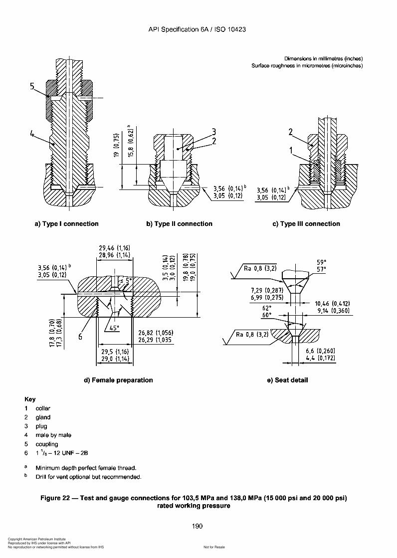
Copyright American Petroleum Institute
Reproduced by IHS under license with API
Not for ResaleNo reproduction or networking permitted without license from IHS
--`,,`,`,-`-`,,`,,`,`,,`---
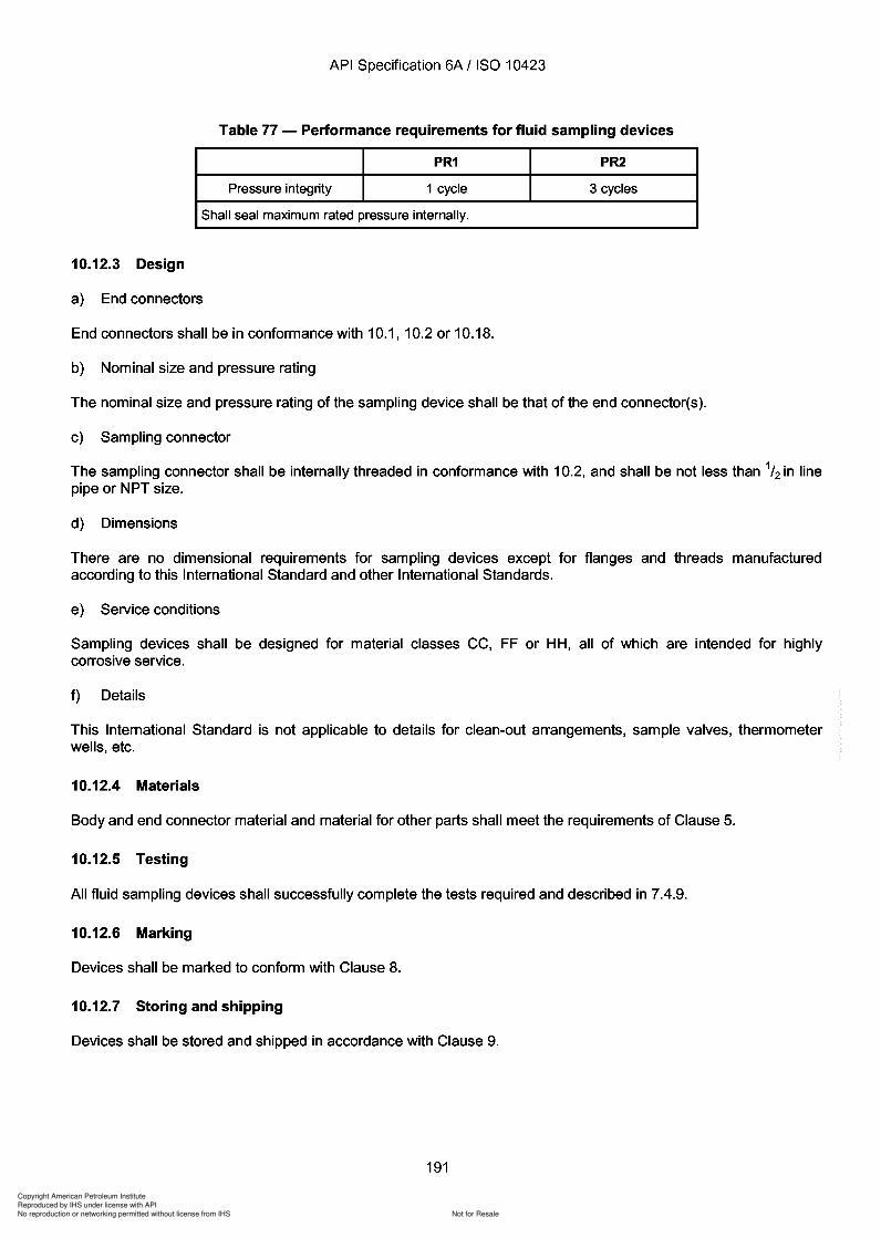
Copyright American Petroleum Institute
Reproduced by IHS under license with API
Not for ResaleNo reproduction or networking permitted without license from IHS
--`,,`,`,-`-`,,`,,`,`,,`---
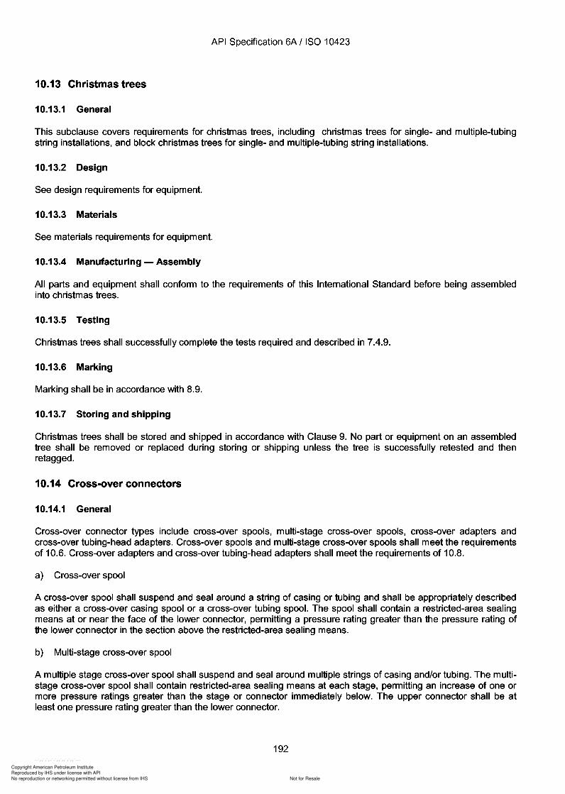
Copyright American Petroleum Institute
Reproduced by IHS under license with API
Not for ResaleNo reproduction or networking permitted without license from IHS
--`,,`,`,-`-`,,`,,`,`,,`---
API Specification 6A / ISO 10423
10.13 Christmas trees
10.13.1 General
This subclause covers requirements for christmas trees, including christmas trees for single- and multiple-tubingstring installations, and block christmas trees for single- and multiple-tubing string installations.
10.13.2 Design
See design requirements for equipment.
10.13.3 Materials
See materials requirements for equipment.
10.13.4 Manufacturing - Assembly
All parts and equipment shall conform to the requirements of this International Standard before being assembledinto christmas trees.
10.13.5 Testing
Christmas trees shall successfully complete the tests required and described in 7.4.9.
10.13.6 Marking
Marking shall be in accordance with 8.9.
10.13.7 Storing and shipping
Christmas trees shall be stored and shipped in accordance with Clause 9. No part or equipment on an assembledtree shall be removed or replaced during storing or shipping unless the tree is successfully retested and thenretagged.
10.14 Cross-over connectors
10.14.1 General
Cross-over connector types include cross-over spools, multi-stage cross-over spools, cross-over adapters andcross-over tubing-head adapters. Cross-over spools and multi-stage cross-over spools shall meet the requirementsof 10.6. Cross-over adapters and cross-over tubing-head adapters shall meet the requirements of 10.8.
a) Cross-over spool
A cross-over spool shall suspend and seal around a string of casing or tubing and shall be appropriately describedas either a cross-over casing spool or a cross-over tubing spool. The spool shall contain a restricted-area sealingmeans at or near the face of the lower connector, permitting a pressure rating greater than the pressure rating ofthe lower connector in the section above the restricted-area sealing means.
b) Multi-stage cross-over spool
A multiple stage cross-over spool shall suspend and seal around multiple strings of casing and/or tubing. The multistage cross-over spool shall contain restricted-area sealing means at each stage, permitting an increase of one ormore pressure ratings greater than the stage or connector immediately below. The upper connector shall be atleast one pressure rating greater than the lower connector.
192
API Specification 6A / ISO 10423
10.13 Christmas trees
10.13.1 General
This subclause covers requirements for christmas trees, including christmas trees for single- and multiple-tubing string installations, and block christmas trees for single- and multiple-tubing string installations.
10.13.2 Design
See design requirements for equipment.
10.13.3 Materials
See materials requirements for equipment.
10.13.4 Manufacturing - Assembly
All parts and equipment shall conform to the requirements of this International Standard before being assembled into christmas trees.
10.13.5 Testing
Christmas trees shall successfully complete the tests required and described in 7.4.9.
10.13.6 Marking
Marking shall be in accordance with 8.9.
10.13.7 Storing and shipping
Christmas trees shall be stored and shipped in accordance with Clause 9. No part or equipment on an assembled tree shall be removed or replaced during storing or shipping unless the tree is successfully retested and then retagged.
10.14 Cross-over connectors
10.14.1 General
Cross-over connector types include cross-over spools, multi-stage cross-over spools, cross-over adapters and cross-over tubing-head adapters. Cross-over spools and multi-stage cross-over spools shall meet the requirements of 10.6. Cross-over adapters and cross-over tubing-head adapters shall meet the requirements of 10.8.
a) Cross-over spool
A cross-over spool shall suspend and seal around a string of casing or tubing and shall be appropriately described as either a cross-over casing spool or a cross-over tubing spool. The spool shall contain a restricted-area sealing means at or near the face of the lower connector, permitting a pressure rating greater than the pressure rating of the lower connector in the section above the restricted-area sealing means.
b) Multi-stage cross-over spool
A multiple stage cross-over spool shall suspend and seal around multiple strings of casing and/or tubing. The multistage cross-over spool shall contain restricted-area sealing means at each stage, permitting an increase of one or more pressure ratings greater than the stage or connector immediately below. The upper connector shall be at least one pressure rating greater than the lower connector.
192
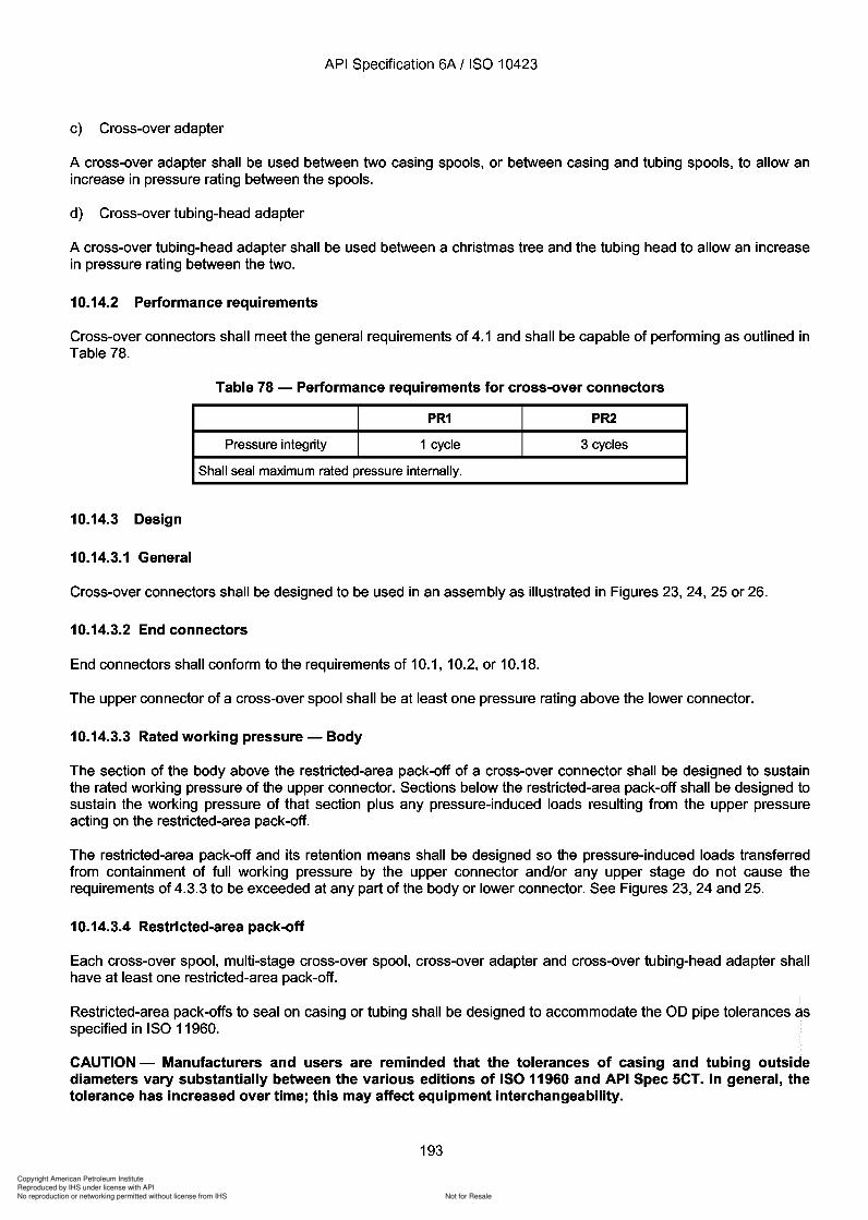
Copyright American Petroleum Institute
Reproduced by IHS under license with API
Not for ResaleNo reproduction or networking permitted without license from IHS
--`,,`,`,-`-`,,`,,`,`,,`---
API Specification 6A / ISO 10423
c) Cross-over adapter
A cross-over adapter shall be used between two casing spools, or between casing and tubing spools, to allow anincrease in pressure rating between the spools.
d) Cross-over tubing-head adapter
A cross-over tubing-head adapter shall be used between a christmas tree and the tubing head to allow an increasein pressure rating between the two.
10.14.2 Performance requirements
Cross-over connectors shall meet the general requirements of 4.1 and shall be capable of performing as outlined inTable 78.
Table 78 - Performance requirements for cross-over connectors
PR1 PR2
Pressure integrity 1 cycle 3 cycles
Shall seal maximum rated pressure internally.
10.14.3 Design
10.14.3.1 General
Cross-over connectors shall be designed to be used in an assembly as illustrated in Figures 23, 24, 25 or 26.
10.14.3.2 End connectors
End connectors shall conform to the requirements of 10.1, 10.2, or 10.18.
The upper connector of a cross-over spool shall be at least one pressure rating above the lower connector.
10.14.3.3 Rated working pressure - Body
The section of the body above the restricted-area pack-off of a cross-over connector shall be designed to sustainthe rated working pressure of the upper connector. Sections below the restricted-area pack-off shall be designed tosustain the working pressure of that section plus any pressure-induced loads resulting from the upper pressureacting on the restricted-area pack-off.
The restricted-area pack-off and its retention means shall be designed so the pressure-induced loads transferredfrom containment of full working pressure by the upper connector and/or any upper stage do not cause therequirements of 4.3.3 to be exceeded at any part of the body or lower connector. See Figures 23, 24 and 25.
10.14.3.4 Restricted-area pack-off
Each cross-over spool, multi-stage cross-over spool, cross-over adapter and cross-over tubing-head adapter shallhave at least one restricted-area pack-off.
Restricted-area pack-offs to seal on casing or tubing shall be designed to accommodate the 00 pipe tolerances asspecified in ISO 11960.
CAUTION - Manufacturers and users are reminded that the tolerances of casing and tubing outsidediameters vary substantially between the various editions of ISO 11960 and API Spec SCT. In general, thetolerance has increased over time; this may affect equipment interchangeability.
193
API Specification 6A / ISO 10423
c) Cross-over adapter
A cross-over adapter shall be used between two casing spools, or between casing and tubing spools, to allow an increase in pressure rating between the spools.
d) Cross-over tubing-head adapter
A cross-over tubing-head adapter shall be used between a christmas tree and the tubing head to allow an increase in pressure rating between the two.
10.14.2 Performance requirements
Cross-over connectors shall meet the general requirements of 4.1 and shall be capable of performing as outlined in Table 78.
Table 78 - Performance requirements for cross-over connectors
PR1 PR2
Pressure integrity 1 cycle 3 cycles
Shall seal maximum rated pressure internally.
10.14.3 Design
10.14.3.1 General
Cross-over connectors shall be designed to be used in an assembly as illustrated in Figures 23, 24, 25 or 26.
10.14.3.2 End connectors
End connectors shall conform to the requirements of 10.1, 10.2, or 10.18.
The upper connector of a cross-over spool shall be at least one pressure rating above the lower connector.
10.14.3.3 Rated working pressure - Body
The section of the body above the restricted-area pack-off of a cross-over connector shall be designed to sustain the rated working pressure of the upper connector. Sections below the restricted-area pack-off shall be designed to sustain the working pressure of that section plus any pressure-induced loads resulting from the upper pressure acting on the restricted-area pack-off.
The restricted-area pack-off and its retention means shall be designed so the pressure-induced loads transferred from containment of full working pressure by the upper connector and/or any upper stage do not cause the requirements of 4.3.3 to be exceeded at any part of the body or lower connector. See Figures 23, 24 and 25.
10.14.3.4 Restricted-area pack-off
Each cross-over spool, multi-stage cross-over spool, cross-over adapter and cross-over tubing-head adapter shall have at least one restricted-area pack-off.
Restricted-area pack-offs to seal on casing or tubing shall be designed to accommodate the 00 pipe tolerances as specified in ISO 11960.
CAUTION - Manufacturers and users are reminded that the tolerances of casing and tubing outside diameters vary substantially between the various editions of ISO 11960 and API Spec SCT. In general, the tolerance has increased over time; this may affect equipment interchangeability.
193

Copyright American Petroleum Institute
Reproduced by IHS under license with API
Not for ResaleNo reproduction or networking permitted without license from IHS
--`,,`,`,-`-`,,`,,`,`,,`---
API Specification 6A / ISO 10423
1
Key1 upper connector2 restricted-area pack-off3 ring gasket
4 lower connector5 spool6 upper pressure rating
7 lower pressure rating8 inner casing9 test port
Figure 23 - Cross-over spool with restricted-area pack-off supported by lower head
1
2
9--J::7:=:::¢:iI/iAII
3
4
Key1 upper connector of spool2 restricted-area pack-off3 ring gasket
8
4 lower connector5 spool6 upper pressure rating
7 lower pressure rating8 inner casing9 test port
2
3
4
Figure 24 - Cross-over spool with restricted-area pack-offs supported by upper spool
194
Key 1 upper connector 2 restricted-area pack-off 3 ring gasket
1
API Specification 6A / ISO 10423
4 lower connector 5 spool 6 upper pressure rating
7 lower pressure rating 8 inner casing 9 test port
Figure 23 - Cross-over spool with restricted-area pack-off supported by lower head
Key
2
9_-t::7==::¢:;v
3
4
1 upper connector of spool 2 restricted-area pack-off 3 ring gasket
4 lower connector 5 spool
1
8
6 upper pressure rating
7 lower pressure rating 8 inner casing 9 test port
2
3
4
Figure 24 - Cross-over spool with restricted-area pack-offs supported by upper spool
194
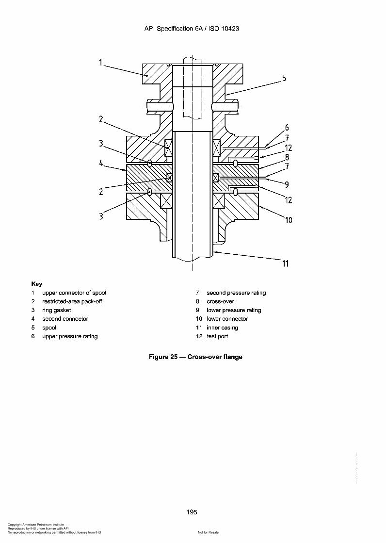
Copyright American Petroleum Institute
Reproduced by IHS under license with API
Not for ResaleNo reproduction or networking permitted without license from IHS
--`,,`,`,-`-`,,`,,`,`,,`---
1
2
3
4
2
3
Key
1 upper connector of spool
2 restricted-area pack-off
3 ring gasket
4 second connector
5 spool
6 upper pressure rating
API Specification 6A / ISO 10423
7 second pressure rating
8 cross-over
9 lower pressure rating
10 lower connector
11 inner casing
12 test port
Figure 25 - Cross-over flange
195
611281
9
12
10
11
1
2
3
4
2
3
Key
1 upper connector of spool
2 restricted-area pack-off
3 ring gasket
4 second connector
5 spool
6 upper pressure rating
API Specification 6A / ISO 10423
7 second pressure rating
8 cross-over
9 lower pressure rating
10 lower connector
11 inner casing
12 test port
Figure 25 - Cross-over flange
195
6 1 12 8 1
9
12
10
11
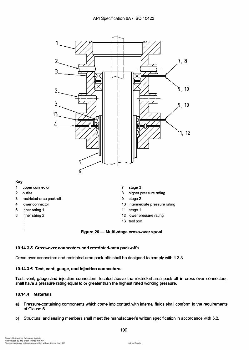
Copyright American Petroleum Institute
Reproduced by IHS under license with API
Not for ResaleNo reproduction or networking permitted without license from IHS
--`,,`,`,-`-`,,`,,`,`,,`---
Copyright American Petroleum Institute
Reproduced by IHS under license with API
Not for ResaleNo reproduction or networking permitted without license from IHS
--`,,`,`,-`-`,,`,,`,`,,`---
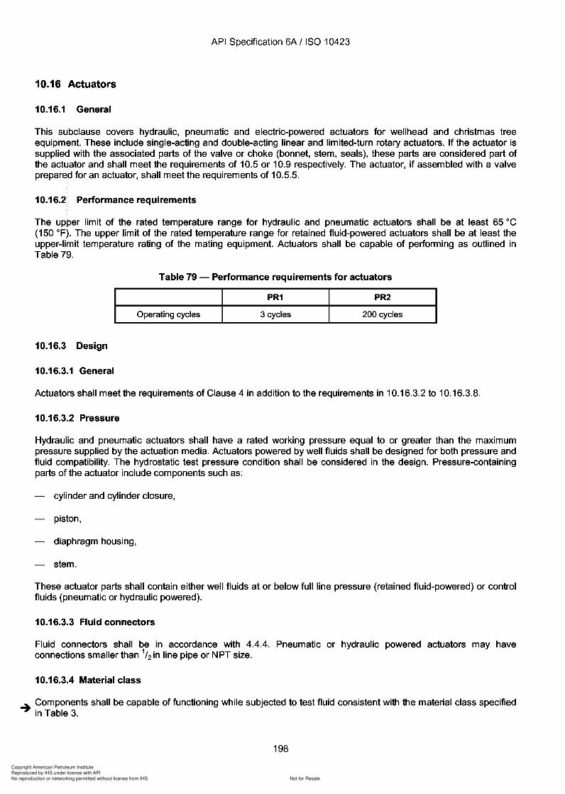
Copyright American Petroleum Institute
Reproduced by IHS under license with API
Not for ResaleNo reproduction or networking permitted without license from IHS
--`,,`,`,-`-`,,`,,`,`,,`---
Copyright American Petroleum Institute
Reproduced by IHS under license with API
Not for ResaleNo reproduction or networking permitted without license from IHS
--`,,`,`,-`-`,,`,,`,`,,`---
Copyright American Petroleum Institute
Reproduced by IHS under license with API
Not for ResaleNo reproduction or networking permitted without license from IHS
--`,,`,`,-`-`,,`,,`,`,,`---
API Specification 6A / ISO 10423
10.16.4.5 Materials for sulfide stress cracking service
Actuators powered by well fluids or control fluids which could cause sulfide stress-cracking shall meet therequirements of 7.4.1.
10.16.4.6 Non-metallic sealing elements
a) General
Non-metallic seal materials shall be capable of withstanding the maximum working pressure within the temperaturerating specified by the manufacturer, and shall be compatible with the designated service.
b) Elastomeric materials
Sealing elements shall be controlled in accordance with 7.4.8.
10.16.5 Welding requirements
a) Retained-fluid powered actuators
Welding on pressure-containing parts of well-fluid powered actuators connected to PSL 1 to PSL 3 valves or toPSL 1 to PSL 3 chokes shall be in accordance with 6.3 and 6.4 for the appropriate PSL. Welding is not permittedon actuators connected to PSL 4 valves or chokes.
b) Pneumatic, hydraulic or electric actuators
Welding on parts which meet material class AA (Table 3) shall be in accordance with 6.3 except that quality controlrequirements shall be visual examination for fabrication welds. Repair welds shall include liquid penetrant ormagnetic-particle examination as applicable for material defects only.
10.16.6 Testing
10.16.6.1 Hydrostatic testing
Pressure-containing parts shall be subjected to a hydrostatic test to demonstrate structural integrity. The pressurecontaining parts may be hydrostatically tested simultaneously or separately. In case the bonnet for the mating valveforms an integral part of a loose actuator, the bonnet shall satisfy the requirements of 10.5 and 10.9. Stems do nothave to be separately tested.
Water with or without additives, gas or hydraulic fluid may be used as the testing fluid.
a) Retained-fluid powered actuators
The test pressure shall be determined by the working pressure rating for the valve or choke to which the actuator isattached. Tests shall be conducted in accordance with the hydrostatic body test (see 7.4.9) for the applicable PSL.
b) Pneumatic, hydraulic or electric actuators
The test pressure shall be a minimum of 1,5 times the maximum working pressure for actuators with a maximumworking pressure less than or equal to 138 MPa (20000 psi); above 138 MPa (20000 psi), the test pressure shallbe a minimum of 1,25 times the maximum working pressure. The test shall consist of three parts:
primary pressure-holding period;
reduction of the pressure to zero;
secondary pressure-holding period.
200
API Specification 6A / ISO 10423
10.16.4.5 Materials for sulfide stress cracking service
Actuators powered by well fluids or control fluids which could cause sulfide stress-cracking shall meet the requirements of 7.4.1.
10.16.4.6 Non-metallic sealing elements
a) General
Non-metallic seal materials shall be capable of withstanding the maximum working pressure within the temperature rating specified by the manufacturer, and shall be compatible with the designated service.
b) Elastomeric materials
Sealing elements shall be controlled in accordance with 7.4.8.
10.16.5 Welding requirements
a) Retained-fluid powered actuators
Welding on pressure-containing parts of well-fluid powered actuators connected to PSL 1 to PSL 3 valves or to PSL 1 to PSL 3 chokes shall be in accordance with 6.3 and 6.4 for the appropriate PSL. Welding is not permitted on actuators connected to PSL 4 valves or chokes.
b) Pneumatic, hydraulic or electric actuators
Welding on parts which meet material class AA (Table 3) shall be in accordance with 6.3 except that quality control requirements shall be visual examination for fabrication welds. Repair welds shall include liquid penetrant or magnetic-particle examination as applicable for material defects only.
10.16.6 Testing
10.16.6.1 Hydrostatic testing
Pressure-containing parts shall be subjected to a hydrostatic test to demonstrate structural integrity. The pressurecontaining parts may be hydrostatically tested simultaneously or separately. In case the bonnet for the mating valve forms an integral part of a loose actuator, the bonnet shall satisfy the requirements of 10.5 and 10.9. Stems do not have to be separately tested.
Water with or without additives, gas or hydraulic fluid may be used as the testing fluid.
a) Retained-fluid powered actuators
The test pressure shall be determined by the working pressure rating for the valve or choke to which the actuator is attached. Tests shall be conducted in accordance with the hydrostatic body test (see 7.4.9) for the applicable PSL.
b) Pneumatic, hydraulic or electric actuators
The test pressure shall be a minimum of 1,5 times the maximum working pressure for actuators with a maximum working pressure less than or equal to 138 MPa (20000 psi); above 138 MPa (20000 psi), the test pressure shall be a minimum of 1,25 times the maximum working pressure. The test shall consist of three parts:
primary pressure-holding period;
reduction of the pressure to zero;
secondary pressure-holding period.
200
Copyright American Petroleum Institute
Reproduced by IHS under license with API
Not for ResaleNo reproduction or networking permitted without license from IHS
--`,,`,`,-`-`,,`,,`,`,,`---
API Specification 6A / ISO 10423
Both pressure-holding periods shall not be less than 3 min. The test period shall not begin until the test pressurehas been reached and has stabilized, the equipment and the pressure-monitoring device have been isolated fromthe pressure source, and the external surfaces of the parts have been thoroughly dried.
c) Acceptance criteria
The equipment shall show no visible leakage during each holding period.
10.16.6.2 Functional testing
Each actuator shall be subjected to a functional test to demonstrate proper assembly and operation. The actuatormay be tested with the equipment for which it is intended, or tested separately. Test media for pneumatic actuatorsshall be a gas such as air or nitrogen. Test media for hydraulic actuators shall be a suitable hydraulic fluid or a gassuch as air or nitrogen. Test power supplied to electric actuators shall be in accordance with the electrical designrequirements.
a) Test for hydraulic and pneumatic actuator seal
The actuator seals shall be pressure-tested in two steps by applying pressures of 20 % and 100 % of the maximumworking pressure to the actuator. No visible leakage is allowed. The minimum test duration for each test pressureshall be 10 min at 20 % pressure and 5 min at 100 % pressure for pneumatic actuators; 3 min at each test pressurefor hydraulic actuators. This test period shall not begin until the test pressure has been reached and has stabilizedand the pressure-monitoring device has been isolated from the pressure source. The test pressure reading andtime at the beginning and at the end of each pressure-holding period shall be recorded.
b) Operational test
The actuator shall be tested for proper operation by cycling the actuator, from the normal position to the fullystroked position, a minimum of three times. The actuator shall operate smoothly in both directions. The finalassembly of actuator to valve or choke shall be tested in accordance with 7.4.9 for the appropriate PSL of theequipment. The latching (hold-open) mechanism power requirements for electric actutors shall be tested during thetests required by 7.4.9.
c) Gas back-seat test
If the bonnet and actuator are furnished as a unit for PSL 4 valves, a test shall be conducted in accordance with7.4.9.6.8. If the bonnet and actuator are furnished as a unit for PSL 3G valves, a test may be conducted inaccordance with 7.4.9.5.9.
10.16.7 Marking
All actuators shall be marked to conform to the requirements of Clause 8.
10.16.8 Storage and shipping
10.16.8.1 Retained-fluid powered actuators
These shall be stored and shipped in accordance with the requirements of Clause 9 for the applicable PSL.
10.16.8.2 Pneumatic, hydraulic and electric actuators
These shall be stored and shipped in accordance with the following:
a) draining after testing (does not apply to electric actuators)
Actuators shall be drained and lubricated after testing and prior to storage or shipment.
201
API Specification 6A / ISO 10423
Both pressure-holding periods shall not be less than 3 min. The test period shall not begin until the test pressure has been reached and has stabilized, the equipment and the pressure-monitoring device have been isolated from the pressure source, and the external surfaces of the parts have been thoroughly dried.
c) Acceptance criteria
The equipment shall show no visible leakage during each holding period.
10.16.6.2 Functional testing
Each actuator shall be subjected to a functional test to demonstrate proper assembly and operation. The actuator may be tested with the equipment for which it is intended, or tested separately. Test media for pneumatic actuators shall be a gas such as air or nitrogen. Test media for hydraulic actuators shall be a suitable hydraulic fluid or a gas such as air or nitrogen. Test power supplied to electric actuators shall be in accordance with the electrical design requirements.
a) Test for hydraulic and pneumatic actuator seal
The actuator seals shall be pressure-tested in two steps by applying pressures of 20 % and 100 % of the maximum working pressure to the actuator. No visible leakage is allowed. The minimum test duration for each test pressure shall be 10 min at 20 % pressure and 5 min at 100 % pressure for pneumatic actuators; 3 min at each test pressure for hydraulic actuators. This test period shall not begin until the test pressure has been reached and has stabilized and the pressure-monitoring device has been isolated from the pressure source. The test pressure reading and time at the beginning and at the end of each pressure-holding period shall be recorded.
b) Operational test
The actuator shall be tested for proper operation by cycling the actuator, from the normal position to the fully stroked position, a minimum of three times. The actuator shall operate smoothly in both directions. The final assembly of actuator to valve or choke shall be tested in accordance with 7.4.9 for the appropriate PSL of the equipment. The latching (hold-open) mechanism power requirements for electric actutors shall be tested during the tests required by 7.4.9.
c) Gas back-seat test
If the bonnet and actuator are furnished as a unit for PSL 4 valves, a test shall be conducted in accordance with 7.4.9.6.8. If the bonnet and actuator are furnished as a unit for PSL 3G valves, a test may be conducted in accordance with 7.4.9.5.9.
10.16.7 Marking
All actuators shall be marked to conform to the requirements of Clause 8.
10.16.8 Storage and shipping
10.16.8.1 Retained-fluid powered actuators
These shall be stored and shipped in accordance with the requirements of Clause 9 for the applicable PSL.
10.16.8.2 Pneumatic, hydraulic and electric actuators
These shall be stored and shipped in accordance with the following:
a) draining after testing (does not apply to electric actuators)
Actuators shall be drained and lubricated after testing and prior to storage or shipment.
201
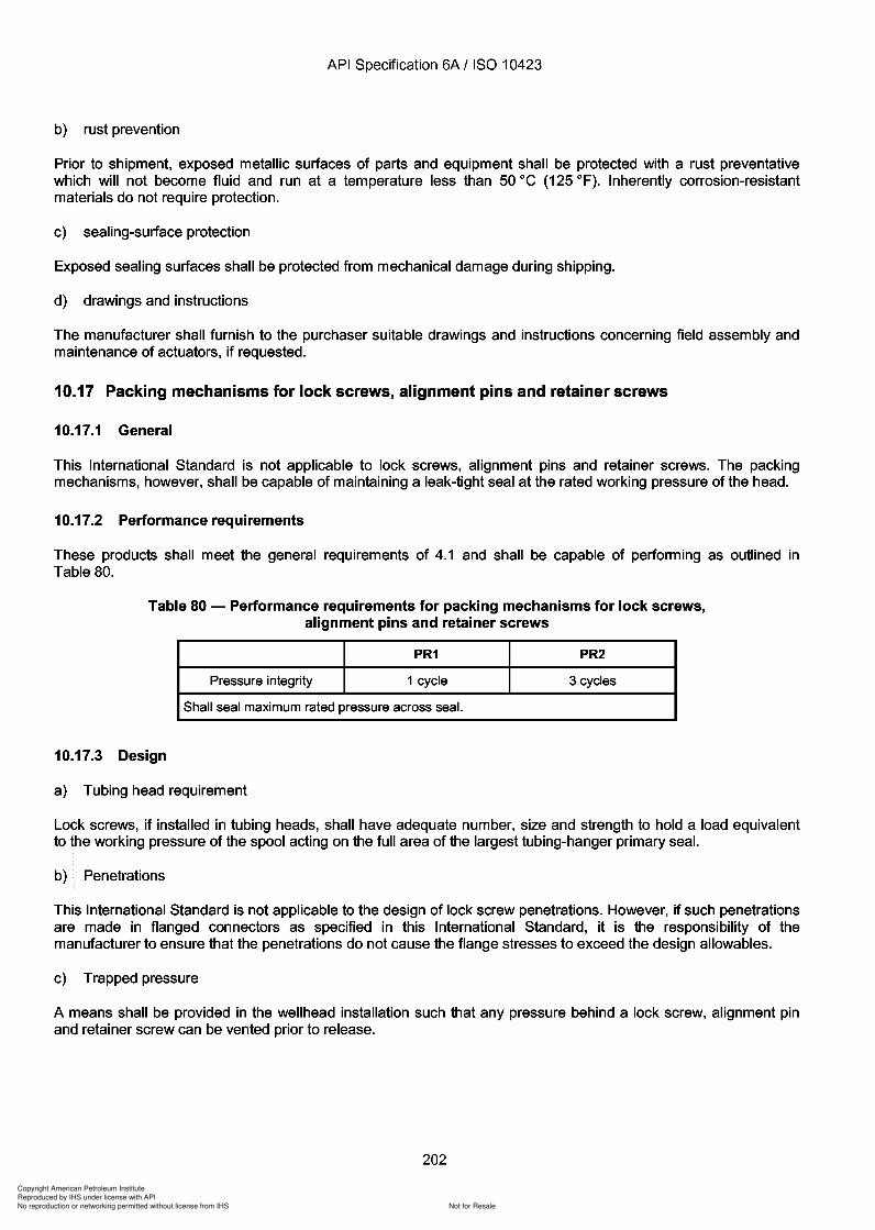
Copyright American Petroleum Institute
Reproduced by IHS under license with API
Not for ResaleNo reproduction or networking permitted without license from IHS
--`,,`,`,-`-`,,`,,`,`,,`---
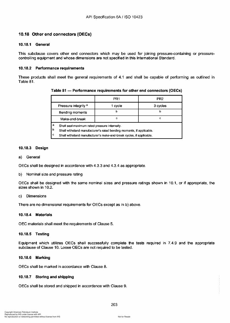
Copyright American Petroleum Institute
Reproduced by IHS under license with API
Not for ResaleNo reproduction or networking permitted without license from IHS
--`,,`,`,-`-`,,`,,`,`,,`---
API Specification 6A / ISO 10423
10.18 Other end connectors (OECs)
10.18.1 General
This subclause covers other end connectors which may be used for joining pressure-containing or pressurecontrolling equipment and whose dimensions are not specified in this International Standard.
10.18.2 Performance requirements
These products shall meet the general requirements of 4.1 and shall be capable of performing as outlined inTable 81.
Table 81 - Performance requirements for other end connectors (OECs)
PR1 PR2
Pressure integrity a 1 cycle 3 cycles
Bending moments b b
Make-and-break c c
a Shall seal maximum rated pressure internally.b Shall withstand manufacturer's rated bending moments, if applicable.c Shall withstand manufacturer's make-and-break cycles, if applicable.
10.18.3 Design
a) General
OECs shall be designed in accordance with 4.3.3 and 4.3.4 as appropriate.
b) Nominal size and pressure rating
OECs shall be designed with the same nominal sizes and pressure ratings shown in 10.1, or if appropriate, thesizes shown in 10.2.
c) Dimensions
There are no dimensional requirements for OECs except as in b) above.
10.18.4 Materials
OEC materials shall meet the requirements of Clause 5.
10.18.5 Testing
Equipment which utilizes OECs shall successfully complete the tests required in 7.4.9 and the appropriatesubclause of Clause 10. Loose OECs are not required to be tested.
10.18.6 Marking
OECs shall be marked in accordance with Clause 8.
10.18.7 Storing and shipping
OECs shall be stored and shipped in accordance with Clause 9.
203
API Specification 6A / ISO 10423
10.18 Other end connectors (OECs)
10.18.1 General
This subclause covers other end connectors which may be used for joining pressure-containing or pressurecontrolling equipment and whose dimensions are not specified in this International Standard.
10.18.2 Performance requirements
These products shall meet the general requirements of 4.1 and shall be capable of performing as outlined in Table 81.
Table 81 - Performance requirements for other end connectors (OECs)
PR1 PR2
Pressure integrity a 1 cycle 3 cycles
Bending moments b b
Make-and-break c c
a Shall seal maximum rated pressure internally. b Shall withstand manufacturer's rated bending moments, if applicable. c Shall withstand manufacturer's make-and-break cycles, if applicable.
10.18.3 Design
a) General
OECs shall be designed in accordance with 4.3.3 and 4.3.4 as appropriate.
b) Nominal size and pressure rating
OECs shall be designed with the same nominal sizes and pressure ratings shown in 10.1, or if appropriate, the sizes shown in 10.2.
c) Dimensions
There are no dimensional requirements for OECs except as in b) above.
10.18.4 Materials
OEC materials shall meet the requirements of Clause 5.
10.18.5 Testing
Equipment which utilizes OECs shall successfully complete the tests required in 7.4.9 and the appropriate subclause of Clause 10. Loose OECs are not required to be tested.
10.18.6 Marking
OECs shall be marked in accordance with Clause 8.
10.18.7 Storing and shipping
OECs shall be stored and shipped in accordance with Clause 9.
203
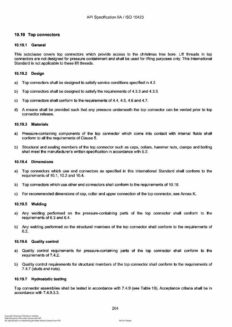
Copyright American Petroleum Institute
Reproduced by IHS under license with API
Not for ResaleNo reproduction or networking permitted without license from IHS
--`,,`,`,-`-`,,`,,`,`,,`---

Copyright American Petroleum Institute
Reproduced by IHS under license with API
Not for ResaleNo reproduction or networking permitted without license from IHS
--`,,`,`,-`-`,,`,,`,`,,`---
Copyright American Petroleum Institute
Reproduced by IHS under license with API
Not for ResaleNo reproduction or networking permitted without license from IHS
--`,,`,`,-`-`,,`,,`,`,,`---
Copyright American Petroleum Institute
Reproduced by IHS under license with API
Not for ResaleNo reproduction or networking permitted without license from IHS
--`,,`,`,-`-`,,`,,`,`,,`---
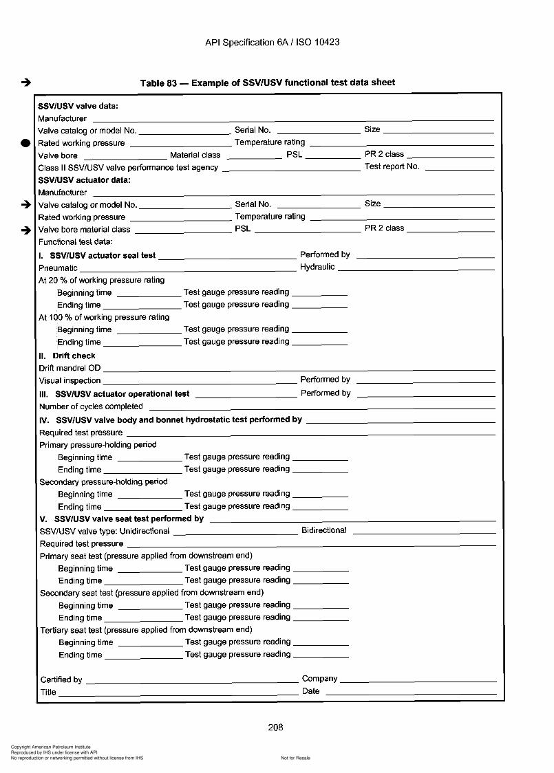
Copyright American Petroleum Institute
Reproduced by IHS under license with API
Not for ResaleNo reproduction or networking permitted without license from IHS
--`,,`,`,-`-`,,`,,`,`,,`---
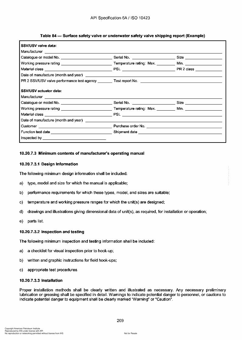
Copyright American Petroleum Institute
Reproduced by IHS under license with API
Not for ResaleNo reproduction or networking permitted without license from IHS
--`,,`,`,-`-`,,`,,`,`,,`---
Copyright American Petroleum Institute
Reproduced by IHS under license with API
Not for ResaleNo reproduction or networking permitted without license from IHS
--`,,`,`,-`-`,,`,,`,`,,`---
API Specification 6A / ISO 10423
10.20.7.3.4 Operation and maintenance
The following minimum operation and maintenance information shall be included:
a) maintenance requirements, including recommended intervals of maintenance;
b) proper operating techniques;
c) disassembly and assembly instructions;
d) assembly diagram showing individual parts in proper relationship to one another;
e) repair instructions and precautions, including a chart listing symptoms, probable cause(s) of the problem, andrepairs necessary.
10.20.7.3.5 Repair and remanufacture
Requirements for repair and remanufacture of SSV/USV equipment, as specified in Annex J.
-+10.21 Bullplugs
10.21.1 General
-+ Bullplugs shall meet the requirements specified for loose connectors.
10.21.2 Design
10.21.2.1 General
The materials and design of bullplugs and threaded connections shall be considered in determining the workingpressure and external load capacity.
10.21.2.2 Dimensions
Bullplugs shall conform to the dimensions and tolerances in Table 85*. Threaded connections shall conform to10.2. This International Standard is not applicable to bullplugs smaller than 1/2 in line pipe or NPT size and largerthan 4 in line pipe size.
10.21.2.3 Rated working pressure
The maximum rated working pressure for bullplugs with line pipe or NPT threads 12,7 mm to 50,8 mm C/2 in to 2 in)shall be as specified in Table 1. This International Standard is not applicable to bullplugs of stronger materials,larger thread dimensions and/or larger designs which are rated for higher working pressures.
10.21.2.4 Thread engagement
Threaded connections shall comply with 10.2. Bullplugs with ISO 10422 line pipe threads shall be assembled withmating parts in conformance with Table 86. Thread compounds tested in accordance with ISO 13678 shall beused.
10.21.3 Materials
Bullplug material shall conform to 5.2 and material requirements of PSL 3. This International Standard is notapplicable to bullplugs and threaded connections with components of less than material designation 60K.
210
API Specification 6A / ISO 10423
10.20.7.3.4 Operation and maintenance
The following minimum operation and maintenance information shall be included:
a) maintenance requirements, including recommended intervals of maintenance;
b) proper operating techniques;
c) disassembly and assembly instructions;
d) assembly diagram showing individual parts in proper relationship to one another;
e) repair instructions and precautions, including a chart listing symptoms, probable cause(s) of the problem, and repairs necessary.
10.20.7.3.5 Repair and remanufacture
Requirements for repair and remanufacture of SSV/USV equipment, as specified in Annex J.
-+ 10.21 Bullplugs
10.21.1 General
-+ Bullplugs shall meet the requirements specified for loose connectors.
10.21.2 Design
10.21.2.1 General
The materials and design of bull plugs and threaded connections shall be considered in determining the working pressure and external load capacity.
10.21.2.2 Dimensions
Bullplugs shall conform to the dimensions and tolerances in Table 85*. Threaded connections shall conform to 10.2. This International Standard is not applicable to bullplugs smaller than 1/2 in line pipe or NPT size and larger than 4 in line pipe size.
10.21.2.3 Rated working pressure
The maximum rated working pressure for bull plugs with line pipe or NPT threads 12,7 mm to 50,8 mm C/2 in to 2 in) shall be as specified in Table 1. This International Standard is not applicable to bullplugs of stronger materials, larger thread dimensions and/or larger designs which are rated for higher working pressures.
10.21.2.4 Thread engagement
Threaded connections shall comply with 10.2. Bullplugs with ISO 10422 line pipe threads shall be assembled with mating parts in conformance with Table 86. Thread compounds tested in accordance with ISO 13678 shall be used.
10.21.3 Materials
Bullplug material shall conform to 5.2 and material requirements of PSL 3. This International Standard is not applicable to bull plugs and threaded connections with components of less than material designation 60K.
210
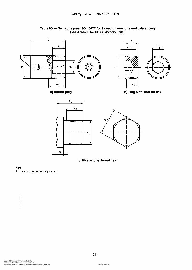
Copyright American Petroleum Institute
Reproduced by IHS under license with API
Not for ResaleNo reproduction or networking permitted without license from IHS
--`,,`,`,-`-`,,`,,`,`,,`---
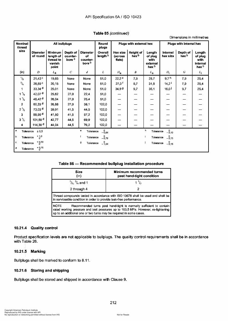
d
Copyright American Petroleum Institute
Reproduced by IHS under license with API
Not for ResaleNo reproduction or networking permitted without license from IHS
--`,,`,`,-`-`,,`,,`,`,,`---
Copyright American Petroleum Institute
Reproduced by IHS under license with API
Not for ResaleNo reproduction or networking permitted without license from IHS
--`,,`,`,-`-`,,`,,`,`,,`---
Copyright American Petroleum Institute
Reproduced by IHS under license with API
Not for ResaleNo reproduction or networking permitted without license from IHS
--`,,`,`,-`-`,,`,,`,`,,`---
API Specification 6A / ISO 10423
10.23.3 Design
This International Standard is not applicable to the design of other pressure-boundary penetrations. However, it isthe responsibility of the manufacturer to specify other pressure-boundary penetrations which have been qualified tomeet performance requirements.
10.23.4 Materials
Body material shall meet the requirements of the manufacturer's written specifications and shall be compatible withthe well fluid.
10.23.5 Marking
There are no marking requirements.
10.23.6 Storing and shipping
Storing and shipping shall be in accordance with Clause 9.
10.24 Back-pressure valves
10.24.1 General
-+ Back-pressure valves shall meet the requirements of tubing hangers.
10.24.2 Design
See 10.21.2.
10.24.3 Materials
Body material shall meet the requirements of 5.11. Material for other parts shall be in accordance with themanufacturer's written specifications.
10.24.4 Quality control
Product specification levels are not applicable to back-pressure valves. The quality control requirements shall be inaccordance with Table 26.
10.24.5 Marking
Marking shall be in accordance with 8.12.
10.24.6 Storing and shipping
Storing and shipping shall be in accordance with Clause 9.
11 Repair and remanufacture
Requirements for repair and remanufacture are specified in Annex J.
214
API Specification 6A / ISO 10423
10.23.3 Design
This International Standard is not applicable to the design of other pressure-boundary penetrations. However, it is the responsibility of the manufacturer to specify other pressure-boundary penetrations which have been qualified to meet performance requirements.
10.23.4 Materials
Body material shall meet the requirements of the manufacturer's written specifications and shall be compatible with the well fluid.
10.23.5 Marking
There are no marking requirements.
10.23.6 Storing and shipping
Storing and shipping shall be in accordance with Clause 9.
10.24 Back-pressure valves
10.24.1 General
-+ Back-pressure valves shall meet the requirements of tubing hangers.
10.24.2 Design
See 10.21.2.
10.24.3 Materials
Body material shall meet the requirements of 5.11. Material for other parts shall be in accordance with the manufacturer's written specifications.
10.24.4 Quality control
Product specification levels are not applicable to back-pressure valves. The quality control requirements shall be in accordance with Table 26.
10.24.5 Marking
Marking shall be in accordance with 8.12.
10.24.6 Storing and shipping
Storing and shipping shall be in accordance with Clause 9.
11 Repair and remanufacture
Requirements for repair and remanufacture are specified in Annex J.
214
Copyright American Petroleum Institute
Reproduced by IHS under license with API
Not for ResaleNo reproduction or networking permitted without license from IHS
--`,,`,`,-`-`,,`,,`,`,,`---
Copyright American Petroleum Institute
Reproduced by IHS under license with API
Not for ResaleNo reproduction or networking permitted without license from IHS
--`,,`,`,-`-`,,`,,`,`,,`---
q
Copyright American Petroleum Institute
Reproduced by IHS under license with API
Not for ResaleNo reproduction or networking permitted without license from IHS
--`,,`,`,-`-`,,`,,`,`,,`---
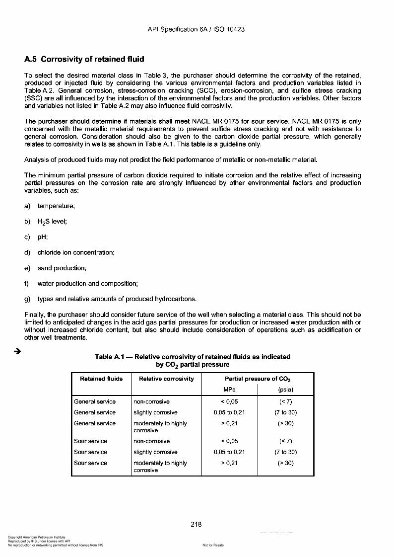
Copyright American Petroleum Institute
Reproduced by IHS under license with API
Not for ResaleNo reproduction or networking permitted without license from IHS
--`,,`,`,-`-`,,`,,`,`,,`---
API Specification 6A / ISO 10423
A.5 Corrosivity of retained fluid
To select the desired material class in Table 3, the purchaser should determine the corrosivity of the retained,produced or injected fluid by considering the various environmental factors and production variables listed inTable A.2. General corrosion, stress-corrosion cracking (SCC), erosion-corrosion, and sulfide stress cracking(SSC) are all influenced by the interaction of the environmental factors and the production variables. Other factorsand variables not listed in Table A.2 may also influence fluid corrosivity.
The purchaser should determine if materials shall meet NACE MR 0175 for sour service. NACE MR 0175 is onlyconcerned with the metallic material requirements to prevent sulfide stress cracking and not with resistance togeneral corrosion. Consideration should also be given to the carbon dioxide partial pressure, which generallyrelates to corrosivity in wells as shown in Table A.1. This table is a guideline only.
Analysis of produced fluids may not predict the field performance of metallic or non-metallic material.
The minimum partial pressure of carbon dioxide required to initiate corrosion and the relative effect of increasingpartial pressures on the corrosion rate are strongly influenced by other environmental factors and productionvariables, such as:
a) temperature;
b) H2S level;
c) pH;
d) chloride ion concentration;
e) sand production;
f) water production and composition;
g) types and relative amounts of produced hydrocarbons.
Finally, the purchaser should consider future service of the well when selecting a material class. This should not belimited to anticipated changes in the acid gas partial pressures for production or increased water production with orwithout increased chloride content, but also should include consideration of operations such as acidification orother well treatments.
Table A.1 - Relative corrosivity of retained fluids as indicatedby CO2 partial pressure
Retained fluids Relative corrosivity Partial pressure of CO2
MPa (psia)
General service non-corrosive < 0,05 « 7)
General service slightly corrosive 0,05 to 0,21 (7 to 30)
General service moderately to highly > 0,21 (> 30)corrosive
Sour service non-corrosive < 0,05 « 7)
Sour service slightly corrosive 0,05 to 0,21 (7 to 30)
Sour service moderately to highly > 0,21 (> 30)corrosive
218
API Specification 6A / ISO 10423
A.S Corrosivity of retained fluid
To select the desired material class in Table 3, the purchaser should determine the corrosivity of the retained, produced or injected fluid by considering the various environmental factors and production variables listed in Table A.2. General corrosion, stress-corrosion cracking (SCC), erosion-corrosion, and sulfide stress cracking (SSC) are all influenced by the interaction of the environmental factors and the production variables. Other factors and variables not listed in Table A.2 may also influence fluid corrosivity.
The purchaser should determine if materials shall meet NACE MR 0175 for sour service. NACE MR 0175 is only concerned with the metallic material requirements to prevent sulfide stress cracking and not with resistance to general corrosion. Consideration should also be given to the carbon dioxide partial pressure, which generally relates to corrosivity in wells as shown in Table A.1. This table is a guideline only.
Analysis of produced fluids may not predict the field performance of metallic or non-metallic material.
The minimum partial pressure of carbon dioxide required to initiate corrosion and the relative effect of increasing partial pressures on the corrosion rate are strongly influenced by other environmental factors and production variables, such as:
a) temperature;
b) H2S level;
c) pH;
d) chloride ion concentration;
e) sand production;
f) water production and composition;
g) types and relative amounts of produced hydrocarbons.
Finally, the purchaser should consider future service of the well when selecting a material class. This should not be limited to anticipated changes in the acid gas partial pressures for production or increased water production with or without increased chloride content, but also should include consideration of operations such as acidification or other well treatments.
Table A.1 - Relative corrosivity of retained fluids as indicated by CO2 partial pressure
Retained fluids Relative corrosivity Partial pressure of CO2
MPa (psi a)
General service non-corrosive < 0,05 « 7)
General service slightly corrosive 0,05 to 0,21 (7 to 30)
General service moderately to highly > 0,21 (> 30) corrosive
Sour service non-corrosive < 0,05 « 7)
Sour service slightly corrosive 0,05 to 0,21 (7 to 30)
Sour service moderately to highly > 0,21 (> 30) corrosive
218

Copyright American Petroleum Institute
Reproduced by IHS under license with API
Not for ResaleNo reproduction or networking permitted without license from IHS
--`,,`,`,-`-`,,`,,`,`,,`---
API Specification 6A / ISO 10423
Table A.2 - Wellhead equipment data sheet - General
~~~~~~Chlorides (~g)
~~~~~~ Other ~~~~~~~_
~ell na~e(s)and location(s~~~~~~~~~~~~~~~~~~~~~~~~~~~~~~~~~_
Maxi~u~ operating pressure: ~~~~~~~~~~~~~~~~~~~~~~~~~~~~~~~~_
Anticipated wellhead shut-in pressure:~~~~~~~~~~~~~~~~~~~~~~~~~~~~~_
Te~perature ranges anticipated: ~~~~~~~~~~~~~~~~~~~~~~~~~~~~~~~_
Mini~u~a~~ent~~peratur~ ~~~~~~~~~~~~~~~~~~~~~~~~~~~~~~~~
Maxi~u~ flowing fluid te~perature at wellhead: ~~~~~~~~~~~~~~~~~~~~~~~~~_
Anticipated co~position of produced fluids: CO2 ~~~~~~~_ (~g)
____________~ H2S (~g)
Anticipated co~pletion or future workover or recovery operations which would affect pressure, te~perature or fluid content:
Batch or continuous inhibition?
Type of acid:~~~~~~~~~~~~~~~
~3/d oil/condensate
New values: ~~~~~~~~~~~~~~~~~~~~~~~~~~~~~~~~~~~~~~_
Are there any govern~ent regulations that apply or ~ust be ~et by this equip~ent? ~~~~~~~~~~~~~_
If so, which one(s)?
~ater or brine pH:
Does NACE MR 0175 apply?~~~~~~~~~~~~~~~~~~~~~~~~~~~~~~~_
~ill scale, paraffin, corrosion or other types of inhibitors be used? ~~~~~~~~~~~~~~~~~~~_
Inhibitor type: Inhibitor carrier: ~ _
~ill acidification be perfor~ed?
Anticipated production rates:
~3/d gas
~3/d S&~ a
Cause: ~~~~~~~~~_
No
No
~ill erosion be a concern?
External coating? Yes, type
Internal coating? Yes, type
Delivery require~ents: ~~~~~~~~~~~~~~_
Special shipping, packing and storage instructions:~~~~~~~~~~~~~~~~~~~~~~~~~_
Casing progra~~e
Top joint in string
Size(00)
kg/~ (Ib/tt) Grade Connection Total stringhangingwt
daN (Ibs)
Bit size~~ (in)
Conductor
Surface casing
Protective casing
Production casing
Tubing
Type of co~pletion: single or ~ultiple
a Sand and water.
219
API Specification 6A / ISO 10423
Table A.2 - Wellhead equipment data sheet - General
~ell na~e(s)and location(s~~~~~~~~~~~~~~~~~~~~~~~~~~~~~~~~~_
Maxi~u~ operating pressure: ~~~~~~~~~~~~~~~~~~~~~~~~~~~~~~~~_
Anticipated wellhead shut-in pressure: ~~~~~~~~~~~~~~~~~~~~~~~~~~~~~_
Te~perature ranges anticipated: ~~~~~~~~~~~~~~~~~~~~~~~~~~~~~~~_
Mini~u~a~~ent~~peratur~ ~~~~~~~~~~~~~~~~~~~~~~~~~~~~~~~~
Maxi~u~ flowing fluid te~perature at wellhead: ~~~~~~~~~~~~~~~~~~~~~~~~~_
Anticipated co~position of produced fluids: CO2 ~~~~~~~_ (~g)
____________ ~ H2S (~g)
~ ____ ~ Chlorides _____ (~g)
~ ____ ~ Other ~~~~~~~_
Anticipated co~pletion or future workover or recovery operations which would affect pressure, te~perature or fluid content:
New values: ~~~~~~~~~~~~~~~~~~~~~~~~~~~~~~~~~~~~~~_
Are there any govern~ent regulations that apply or ~ust be ~et by this equip~ent? ~~~~~~~~~~~~~_
If so, which one(s)?
~ater or brine pH:
Does NACE MR 0175 apply? _______________________________ _
~ill scale, paraffin, corrosion or other types of inhibitors be used? ~~~~~~~~~~~~~~~~~~~_
Inhibitor type: ~~~~~~_ Inhibitor carrier: ~ ___ _
~ill acidification be perfor~ed?
Anticipated production rates:
~ill erosion be a concern?
External coating? Yes, type
Internal coating? Yes, type
Delivery require~ents: ~~~~~~~~~~~~~~_
Batch or continuous inhibition?
Type of acid: ~~~~~~~~~~~~~~_
~3/d oil/condensate
~3/d gas
~3/d S&~ a
Cause: ~~~~~~~~~_
No
No
Special shipping, packing and storage instructions: ~~~~~~~~~~~~~~~~~~~~~~~~~_
Casing progra~~e
Conductor
Surface casing
Protective casing
Production casing
Tubing
Size (00)
Type of co~pletion: single or ~ultiple
a Sand and water.
kg/~ (Ib/ft)
Top joint in string
Grade
219
Connection Total string hangingwt
daN (Ibs)
Bit size ~~ (in)
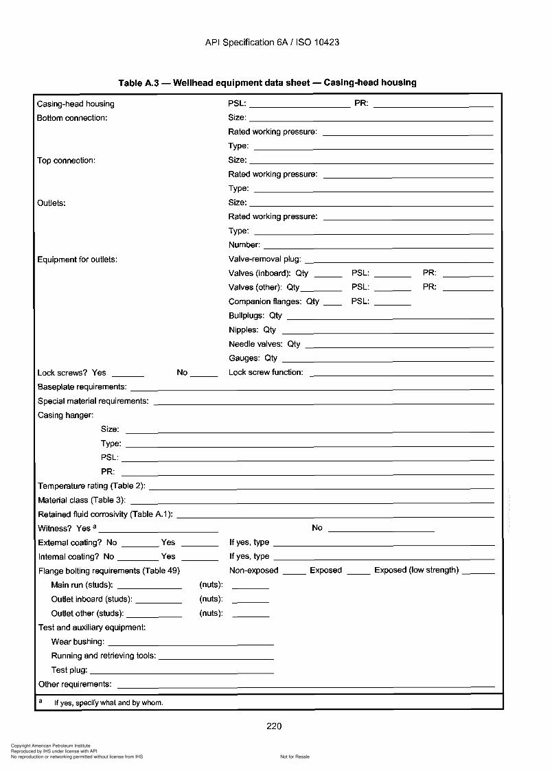
Copyright American Petroleum Institute
Reproduced by IHS under license with API
Not for ResaleNo reproduction or networking permitted without license from IHS
--`,,`,`,-`-`,,`,,`,`,,`---
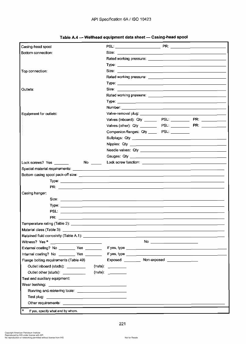
Copyright American Petroleum Institute
Reproduced by IHS under license with API
Not for ResaleNo reproduction or networking permitted without license from IHS
--`,,`,`,-`-`,,`,,`,`,,`---
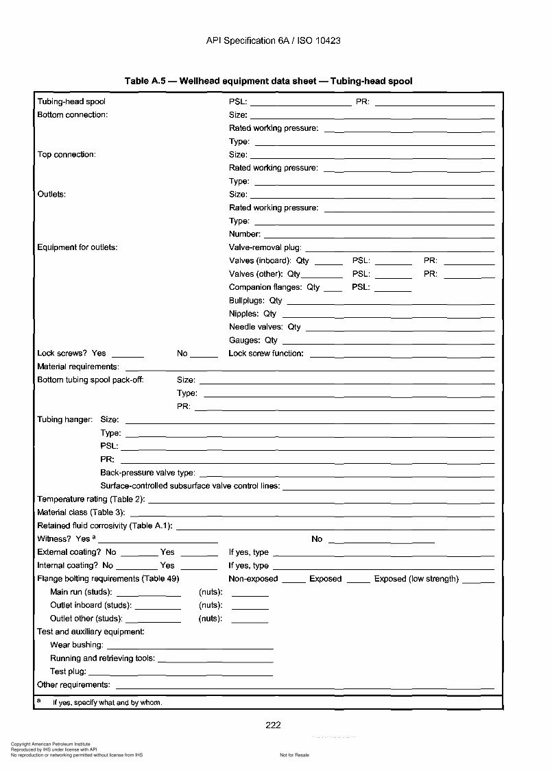
Copyright American Petroleum Institute
Reproduced by IHS under license with API
Not for ResaleNo reproduction or networking permitted without license from IHS
--`,,`,`,-`-`,,`,,`,`,,`---
API Specification 6A / ISO 10423
Table A.5 - Wellhead equipment data sheet - Tubing-head spool
Size: _
Type:
PR: _
PR:
PR:
PSL: _
PSL: _
PSL: _
PSL: PR:
Size: _
Rated working pressure:
Type:
Size: _
Rated working pressure:
Type: _
Size: _
Rated working pressure:
Type: _
Number: _
Valve-removal plug: _
Valves (inboard): Qty _
Valves (other): Qty _
Companion flanges: Qty __
Bullplugs: Qty _
Nipples: Qty
Needle valves: Qty _
Gauges: Qty _
No Lock screw function:
Outlets:
Top connection:
Tubing-head spool
Bottom connection:
Equipment for outlets:
Lock screws? Yes
Material requirements:
Bottom tubing spool pack-off:
No
If yes, type _
If yes, type _
Non-exposed __ Exposed __ Exposed (low strength) _
(nuts):
(nuts):
(nuts):
Tubing hanger: Size:
Type: _
PSL: _
PR:
Back-pressure valve type: _
Surface-controlled subsurface valve control lines: _
Temperature rating (Table 2): _
Material class (Table 3):
Retained fluid corrosivity (Table A.1): _
Witness? Yes a _
External coating? No Yes
Internal coating? No Yes
Flange bolting requirements (Table 49)
Main run (studs): _
Outlet inboard (studs): _
Outlet other (studs): _
Test and auxiliary equipment:
Wear bushing: _
Running and retrieving tools: _
Test plug: _
Other requirements:
a If yes, specify what and by whom.
222
API Specification 6A / ISO 10423
Table A.S - Wellhead equipment data sheet - Tubing-head spool
Tubing-head spool
Bottom connection:
Top connection:
Outlets:
Equipment for outlets:
Lock screws? Yes
Material requirements:
No __ _
PSL: _________________ PR: __________ _
Size: ______________________ _
Rated working pressure:
Type:
Size: ______________________ _
Rated working pressure:
Type:
Size: ______________________ _
Rated working pressure:
Type: Number: _____________________ _
Valve-removal plug: _________________ _
Valves (inboard): Qty PSL: ___ _ PR:
Valves (other): Qty ______ _ PSL: ___ _ PR:
Companion flanges: Qty ___ PSL: ___ _
Bullplugs: Qty _________________ _
Nipples: Qty
Needle valves: Qty _________________ _
Gauges: Qty __________________ ___
Lock screw function:
Bottom tubing spool pack-off: Size: ___________________________ _
Type: PR: ____________________________ _
Tubing hanger: Size: Type: _________________________________ _
PSL: ________________________________ _
PR:
Back-pressure valve type: ___________________________ _
Surface-controlled subsurface valve control lines: ___________________ _
Temperature rating (Table 2): ________________________________ _
Material class (Table 3):
Retained fluid corrosivity (Table A.1): _____________________________ _
Witness? Yes a ___________ _
External coating? No ____ yes
Internal coating? No Yes
Flange bolting requirements (Table 49)
Main run (studs): _____ _
Outlet inboard (studs): ____ _
Outlet other (studs): ____ _
Test and auxiliary equipment:
(nuts):
(nuts):
(nuts):
No
If yes, type ___________________ _
If yes, type ___________________ _
Non-exposed ___ Exposed ___ Exposed (low strength) __ _
Wear bushing: _______________ _
Running and retrieving tools: __________ _
Test plug: ________________ _
Other requirements:
a If yes, specify what and by whom.
222
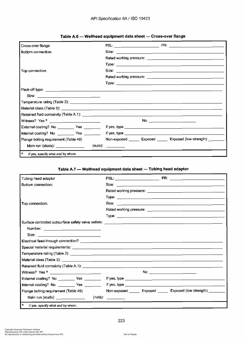
Copyright American Petroleum Institute
Reproduced by IHS under license with API
Not for ResaleNo reproduction or networking permitted without license from IHS
--`,,`,`,-`-`,,`,,`,`,,`---

Copyright American Petroleum Institute
Reproduced by IHS under license with API
Not for ResaleNo reproduction or networking permitted without license from IHS
--`,,`,`,-`-`,,`,,`,`,,`---
API Specification 6A / ISO 10423
Table A.8 - Wellhead equipment data sheet - Christmas tree and choke
Christmas tree - Single _ Dual
Size
Solid block Stacked
External Flangedcoating? bolting RingIf yes, requirements C gasket
Material a PSL PR Witness? b state type Studs Nuts type
If yes, specify class I or II below PR column
If yes, specify class I or II below PR column
If yes, specify class I or II below PR column
No
No
No
Nominal size: _
Yes
Yes
Yes
Lower master valve _
Upper master valve _
Swab (crown) valve
Wing valve-inboard _
Wing valve(s)-other
Tee/cross (circle one) _
Choke _
End flange
Companion flanges _
Instrument flanges
Tree cap/top conn. _
Rated working pressure: _
Retained fluid corrosivity (Table A.1): _
Temperature rating (Table 2): _
Material class (Table 3): _
Upper master prepared for actuator:
Wing valve-inboard prepared for actuator:
Wing valve-other prepared for actuator:
Choke: adjustable or fixed: _
Orifice size: _
Pressure drop:
Flowline connection: Size: _
Hydr.lpiston Electric
Hydr.ldiaphragm Electric
Hydr.lpiston Electric
Hydr.ldiaphragm Electric
Pneu.lpiston _
Pneu.ldiaphragm _
Pneu.lpiston _
Pneu.ldiaphragm _
Type: _
S~d~m~~~~qui~m~~: _
Other requirements:
Upper master valve type actuator requirements:
Supply pressure/power _
Air Gas
Wing valve type actuator requirements:
Supply pressure: _
Other: _
a Define or specify material requirements and, if cladding or other corrosion-resistant materials are to be inlaid, state base materialtype/clad material type, e.g. 4130/625.
b If yes, specify what and by whom.
C Indicate required bolting for the applicable retained fluid and temperature classification specified in Table 49.
224
API Specification 6A / ISO 10423
Table A.8 - Wellhead equipment data sheet - Christmas tree and choke
Christmas tree - Single _ Dual Solid block Stacked
External Flanged coating? bolting Ring If yes, requirements C gasket
Size Material a PSL PR Witness? b state type Studs Nuts type
Lowermastervalve _________________________________________________________________________ __
Uppermastervalve _________________________________________________________________________ __
Swab (crown) valve
Wing valve-inboard ________________________________________________________________________ _
Wing valve(s)-other
Tee/cross (circle one) ________________________________________________________________________ __
Choke ________________________________________________________________________________ _
End flange
Companion flanges _________________________________________________________________________ __
Instrument flanges
Tree cap/top conn. _________________________________________________________________________ __
Rated working pressure: _____________________________________________________________________ _
Retained fluid corrosivity (Table A.1): __________________________________________________________ _
Temperature rating (Table 2): ________________________________________________________________ _
Material class (Table 3): ____________________________________________________________________ _
Upper master prepared for actuator:
Wing valve-inboard prepared for actuator:
Wing valve-other prepared for actuator:
Yes
Yes
Yes
No
No
No
If yes, specify class I or II below PR column
If yes, specify class I or II below PR column
If yes, specify class I or II below PR column
Choke: adjustable or fixed: ____________________________________________________________________ _
Orifice size: ________________________________ _ Nominal size: ________________________________ _
Pressure drop:
Flowline connection: Size: _______________________________________________________________ _
Type: __________________________________________________________ __
S~d~m~~~~qui~m~~: __________________________________________________________________ _
Other requirements:
Upper master valve type actuator requirements: Pneu./piston ____________ _ Hydr./piston ________ Electric
Supply pressure/power Pneu./diaphragm ________ __ Hydr./diaphragm Electric
Air _________ __ Gas
Wing valve type actuator requirements: Pneu./piston ____________ _ Hydr./piston ________ Electric
Pneu./diaphragm ________ __ Hydr./diaphragm Electric
Supply pressure: ____________________ _
Other: ________________________________________________________________________________ _
a Define or specify material requirements and, if cladding or other corrosion-resistant materials are to be inlaid, state base material type/clad material type, e.g. 4130/625.
b If yes, specify what and by whom. C Indicate required bolting for the applicable retained fluid and temperature classification specified in Table 49.
224
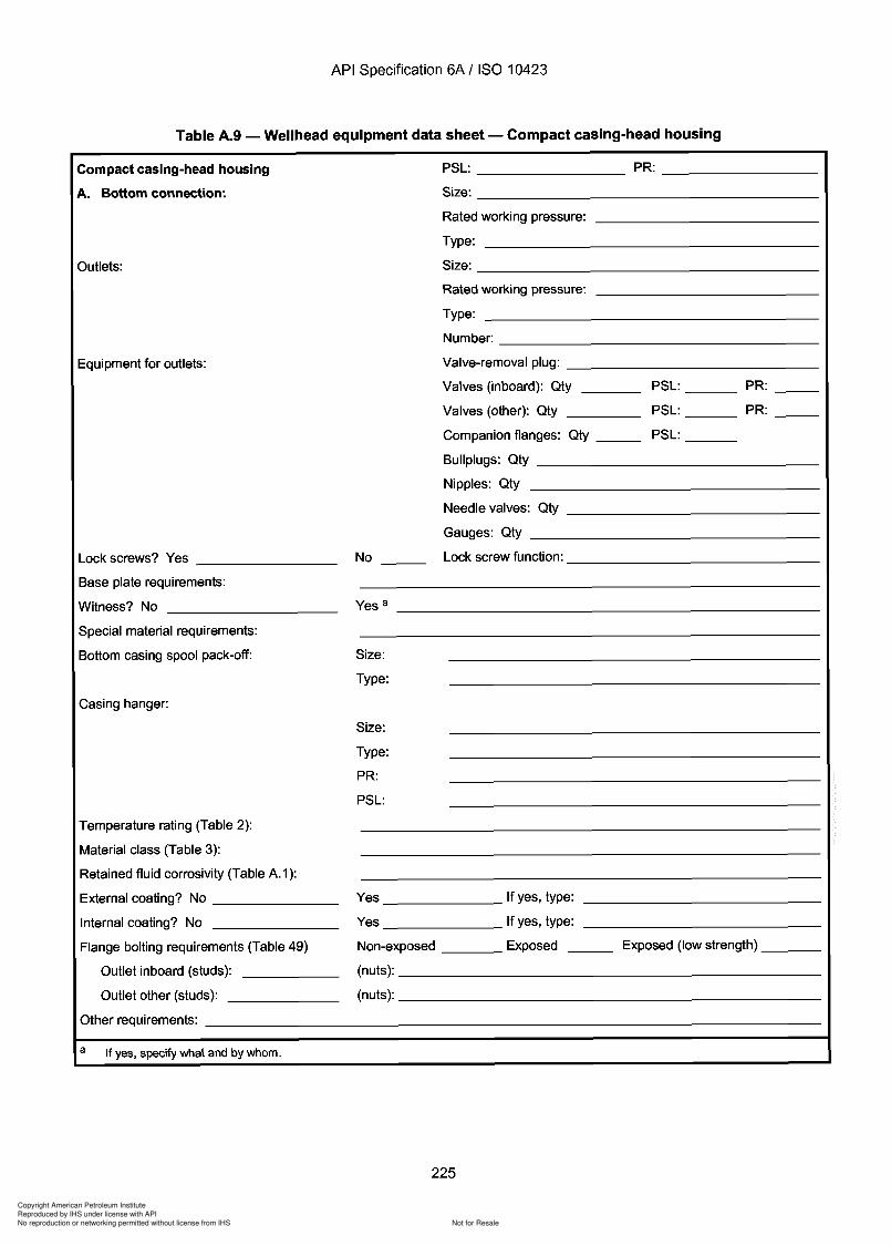
Copyright American Petroleum Institute
Reproduced by IHS under license with API
Not for ResaleNo reproduction or networking permitted without license from IHS
--`,,`,`,-`-`,,`,,`,`,,`---
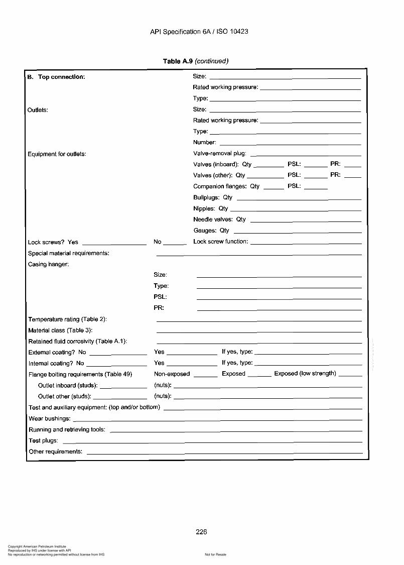
Copyright American Petroleum Institute
Reproduced by IHS under license with API
Not for ResaleNo reproduction or networking permitted without license from IHS
--`,,`,`,-`-`,,`,,`,`,,`---
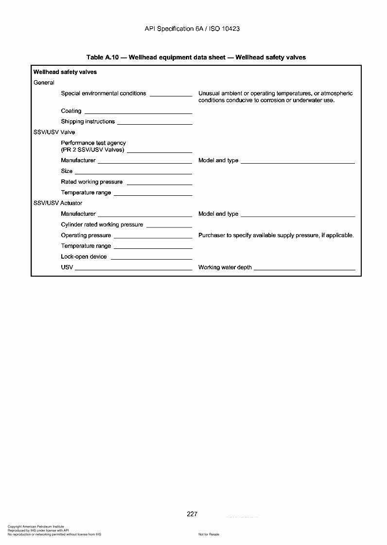
Copyright American Petroleum Institute
Reproduced by IHS under license with API
Not for ResaleNo reproduction or networking permitted without license from IHS
--`,,`,`,-`-`,,`,,`,`,,`---
API Specification 6A / ISO 10423
Table A.10 - Wellhead equipment data sheet - Wellhead safety valves
Wellhead safety valves
General
Special environmental conditions _
Coating _
Shipping instructions _
SSV/USV Valve
Performance test agency(PR 2 SSV/USV Valves) _
Manufacturer _
Size _
Rated working pressure
Temperature range _
SSV/USV Actuator
Manufacturer _
Cylinder rated working pressure _
Operating pressure _
Temperature range _
Lock-open device
USV _
227
Unusual ambient or operating temperatures, or atmosphericconditions conducive to corrosion or underwater use.
Model and type _
Model and type _
Purchaser to specify available supply pressure, if applicable.
Working water depth _
API Specification 6A / ISO 10423
Table A.10 - Wellhead equipment data sheet - Wellhead safety valves
Wellhead safety valves
General
Special environmental conditions _____ _
Coating ______________ _
Shipping instructions _________ _
SSV/USV Valve
Performance test agency (PR 2 SSV/USV Valves) _______ _
Manufacturer ____________ _
Size _______________ _
Rated working pressure
Temperature range __________ _
SSV/USV Actuator
Manufacturer ____________ _
Cylinder rated working pressure _____ _
Operating pressure __________ _
Temperature range __________ _
Lock-open device
USV _____________ _
227
Unusual ambient or operating temperatures, or atmospheric conditions conducive to corrosion or underwater use.
Model and type ______________ _
Model and type ______________ _
Purchaser to specify available supply pressure, if applicable.
Working water depth _____________ _
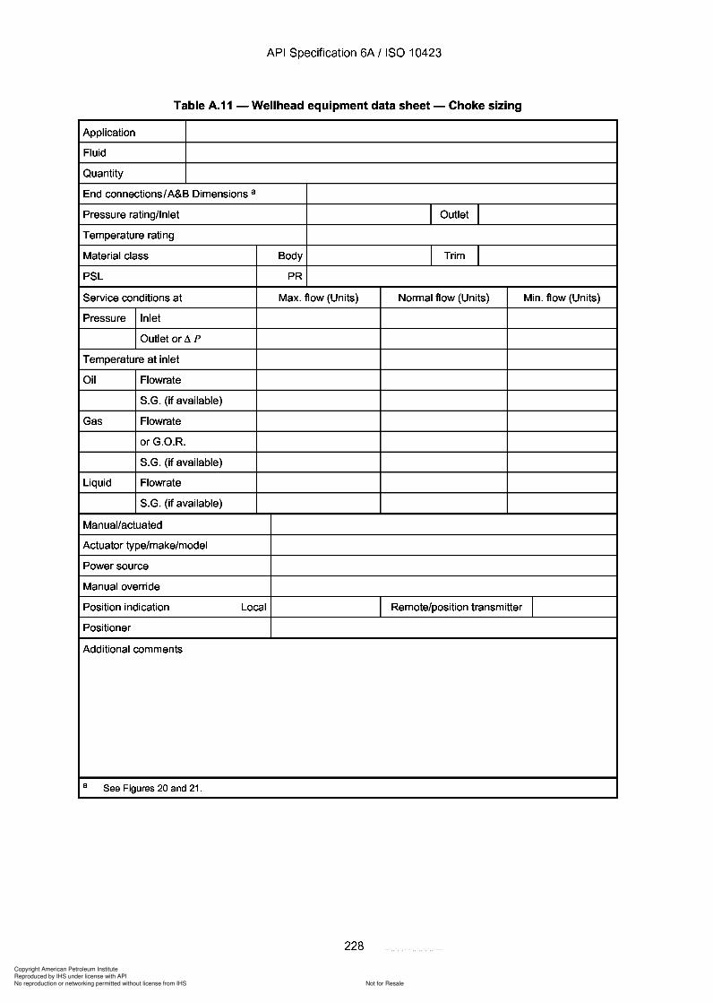
Copyright American Petroleum Institute
Reproduced by IHS under license with API
Not for ResaleNo reproduction or networking permitted without license from IHS
--`,,`,`,-`-`,,`,,`,`,,`---
API Specification 6A / ISO 10423
Table A.11 - Wellhead equipment data sheet - Choke sizing
Application
Fluid
Quantity
End connections/A&B Dimensions a
Pressure rating/Inlet I Outlet ITemperature rating
Material class Body I Trim IPSL PR
Service conditions at Max. flow (Units) Normal flow (Units) Min. flow (Units)
Pressure Inlet
Outlet or.<iP
Temperature at inlet
Oil Flowrate
S.G. (if available)
Gas Flowrate
orG.O.R.
S.G. (if available)
Liquid Flowrate
S.G. (if available)
Manual/actuated
Actuator type/make/model
Power source
Manual override
Position indication Local Remote/position transmitter IPositioner
Additional comments
a See Figures 20 and 21.
228
API Specification 6A / ISO 10423
Table A.11 - Wellhead equipment data sheet - Choke sizing
Application
Fluid
Quantity
End connections/ A&B Dimensions a
Pressure rating/Inlet I Outlet I Temperature rating
Material class Body I Trim I PSL PR
Service conditions at Max. flow (Units) Normal flow (Units) Min. flow (Units)
Pressure Inlet
Outlet or ,i P
Temperature at inlet
Oil Flowrate
S.G. (if available)
Gas Flowrate
orG.O.R.
S.G. (if available)
Liquid Flowrate
S.G. (if available)
Manual/actuated
Actuator type/make/model
Power source
Manual override
Position indication Local Remote/position transmitter I Positioner
Additional comments
a See Figures 20 and 21.
228
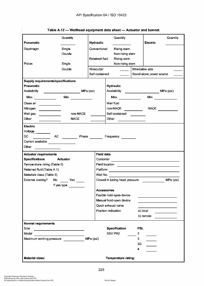
Copyright American Petroleum Institute
Reproduced by IHS under license with API
Not for ResaleNo reproduction or networking permitted without license from IHS
--`,,`,`,-`-`,,`,,`,`,,`---
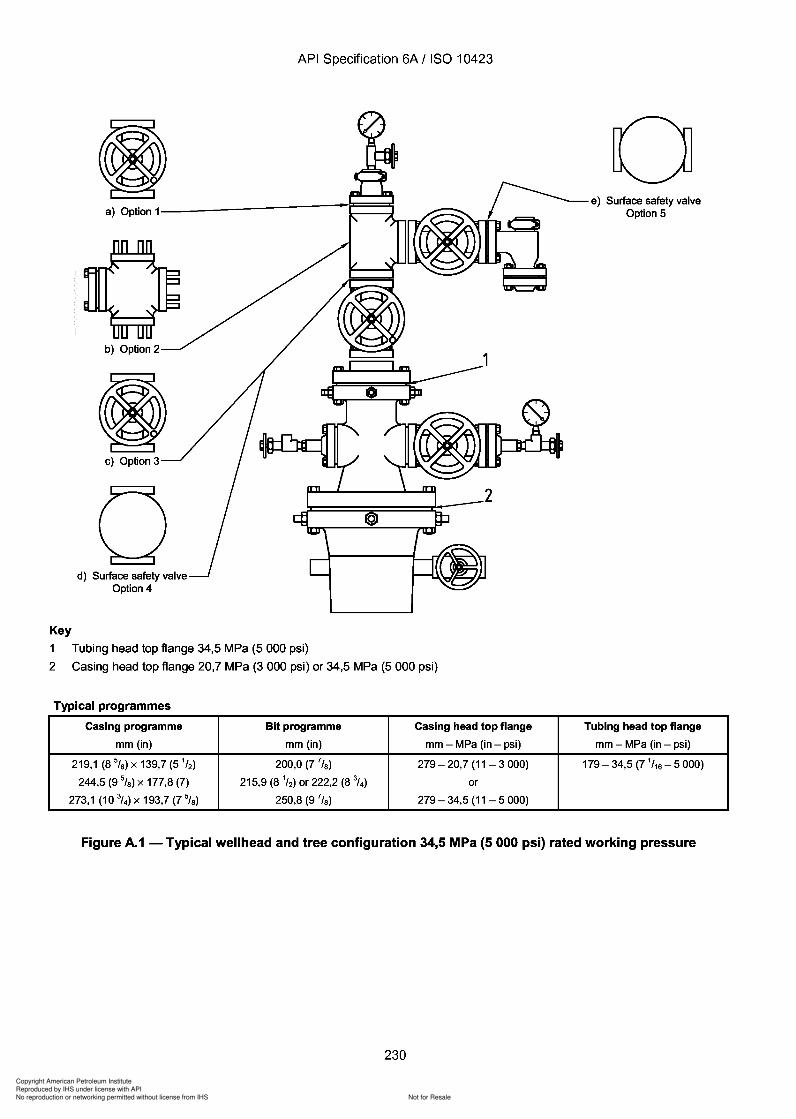
Copyright American Petroleum Institute
Reproduced by IHS under license with API
Not for ResaleNo reproduction or networking permitted without license from IHS
--`,,`,`,-`-`,,`,,`,`,,`---
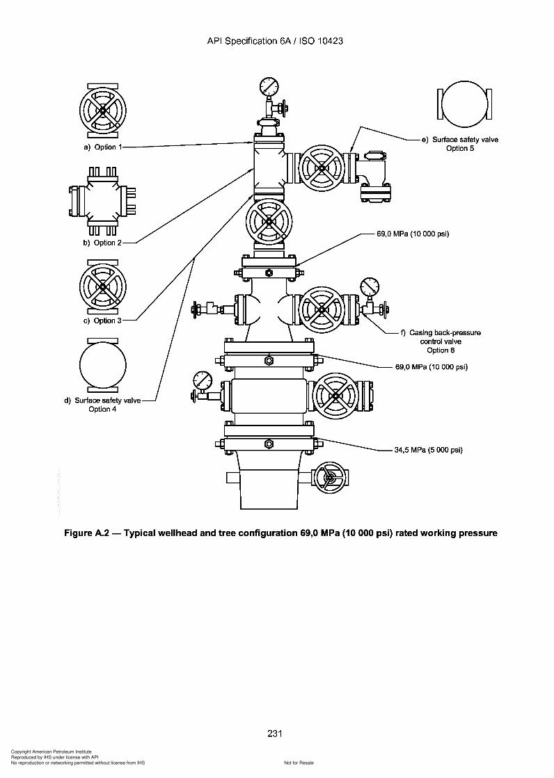
9
Copyright American Petroleum Institute
Reproduced by IHS under license with API
Not for ResaleNo reproduction or networking permitted without license from IHS
--`,,`,`,-`-`,,`,,`,`,,`---
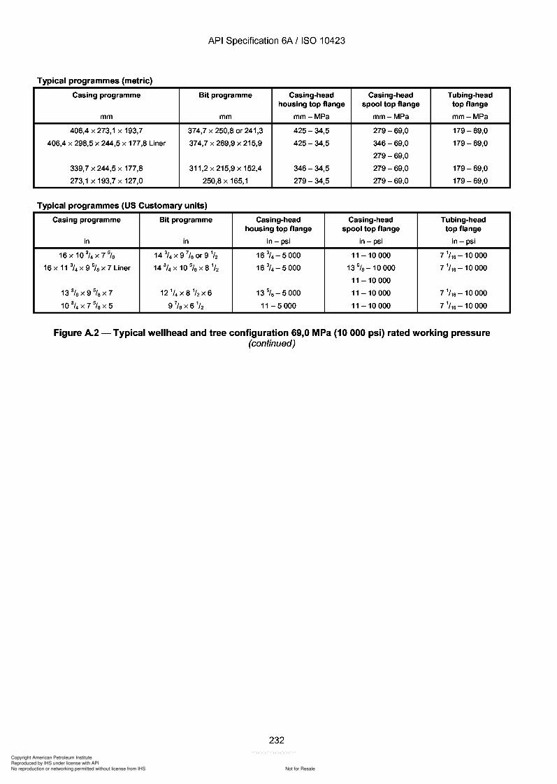
Copyright American Petroleum Institute
Reproduced by IHS under license with API
Not for ResaleNo reproduction or networking permitted without license from IHS
--`,,`,`,-`-`,,`,,`,`,,`---
API Specification 6A / ISO 10423
Typical programmes (metric)
Casing programme Bit programme Casing-head Casing-head Tubing-headhousing top flange spool top flange top flange
mm mm mm-MPa mm-MPa mm-MPa
406,4 x 273,1 x 193,7 374,7 x 250,8 or 241,3 425-34,5 279-69,0 179-69,0
406,4 x 298,5 x 244,5 x 177,8 Liner 374,7 x 269,9 x 215,9 425-34,5 346-69,0 179-69,0
279-69,0
339,7 x 244,5 x 177,8 311,2 x 215,9 x 152,4 346-34,5 279-69,0 179-69,0
273,1 x 193,7 x 127,0 250,8 x 165,1 279-34,5 279-69,0 179-69,0
Typical programmes (US Customary units)
Casing programme Bit programme Casing-head Casing-head Tubing-headhousing top flange spool top flange top flange
in in in- psi in- psi in- psi
16x10 3/4 x7% 14 3/4 x9 7/s or9 1
/2 16 314 -5000 11 - 10 000 7 1/16 -10 000
16 x 11 3/4 x 9 % x 7 Liner 14 314 x 10 5/s x 8 1/2 16 3
/ 4 -5000 13 5/s -10000 7 1
/16 -10 000
11 - 10 000
133tsx9%X7 12 1/4 x8 1
/ 2 x6 13%-5000 11 - 10 000 7 1/ 16 -10 000
10 3/4 x7%x5 9 7/s x 6 1
/2 11-5000 11 - 10 000 7 1/16 -10 000
Figure A.2 - Typical wellhead and tree configuration 69,0 MPa (10 000 psi) rated working pressure(continued)
232
API Specification 6A / ISO 10423
Typical programmes (metric)
Casing programme Bit programme Casing-head Casing-head Tubing-head housing top flange spool top flange top flange
mm mm mm-MPa mm-MPa mm-MPa
406,4 x 273,1 x 193,7 374,7 x 250,8 or 241,3 425-34,5 279-69,0 179-69,0
406,4 x 298,5 x 244,5 x 177,8 Liner 374,7 x 269,9 x 215,9 425-34,5 346-69,0 179-69,0
279-69,0
339,7 x 244,5 x 177,8 311,2 x 215,9 x 152,4 346-34,5 279-69,0 179-69,0
273,1 x 193,7 x 127,0 250,8 x 165,1 279-34,5 279-69,0 179-69,0
Typical programmes (US Customary units)
Casing programme Bit programme Casing-head Casing-head Tubing-head housing top flange spool top flange top flange
in in in- psi in- psi in- psi
16x10 3/4 x7% 14 3/4X 9 7/8 or9 1
/2 16 3/ 4 -5000 11 - 10 000 7 1
/ 16 -10 000
16 x 11 3/4 x 9 % x 7 Liner 14 3/4 x 10 5
/8 X 8 1/2 16 3
/ 4 -5000 13 5/8 -10000 7 1
/ 16 -10 000
11 - 10 000
13%x9%x7 12 1/4 x8 1
/ 2 x6 13%-5000 11 - 10 000 7 1/ 16 -10 000
10 3/4 x7%x5 9 7
/ 8 x 6 1/ 2 11-5000 11 - 10 000 7 1
/ 16 -10 000
Figure A.2 - Typical wellhead and tree configuration 69,0 MPa (10 000 psi) rated working pressure (continued)
232
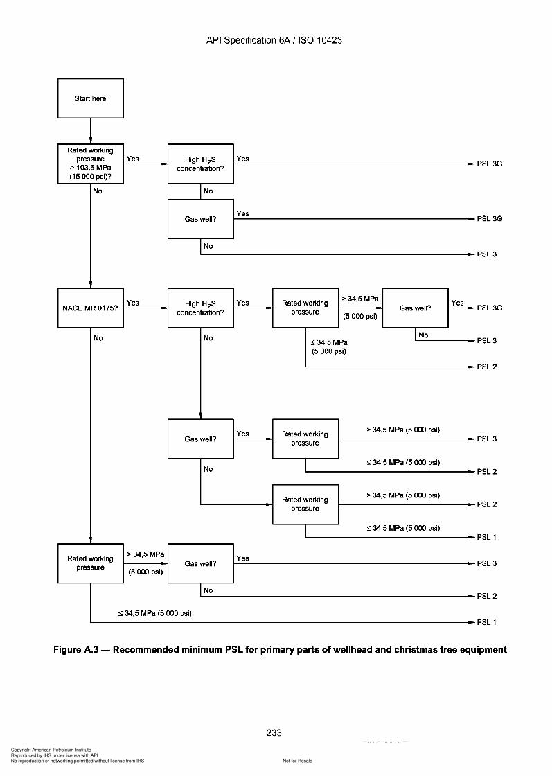
343
343
Copyright American Petroleum Institute
Reproduced by IHS under license with API
Not for ResaleNo reproduction or networking permitted without license from IHS
--`,,`,`,-`-`,,`,,`,`,,`---
API Specification 6A / ISO 10423
Start here
Rated workingpressure Yes High H2S Yes
~ 103,5 MPa concentration?(15 000 psi)?
No No
Gas well?Yes
No
Yes High H2S Yes Rated working> 34,5 MPa
YesNACE MR 0175?
concentration? pressure Gas well?(5 000 psi)
No No INo~34,5 MPa(5 000 psi)
Yes Rated working> 34,5 MPa (5 000 psi)
Gas well? pressure
No~ 34,5 MPa (5 000 psi)
Rated working> 34,5 MPa (5 000 psi)
pressure
~ 34,5 MPa (5 000 psi)
Rated working> 34,5 MPa
Yespressure Gas well?
(5 000 psi)
No
~ 34,5 MPa (5 000 psi)
PSL3G
PSL3G
PSL3
PSL3G
PSL3
PSL2
PSL3
PSL2
PSL2
PSL 1
PSL3
PSL2
PSL 1
Figure A.3 - Recommended minimum PSL for primary parts of wellhead and christmas tree equipment
233
API Specification 6A / ISO 10423
Start here
Rated working pressure Yes High H2S Yes
~ 103,5 MPa concentration? PSL3G
(15 000 psi)?
No No
Gas well? Yes
PSL3G
No PSL3
Yes High H2S Yes Rated working > 34,5 MPa
Yes NACE MR 0175?
concentration? pressure Gas well? (5 000 psi)
PSL3G
No No ~34,5 MPa
I No PSL3
(5 000 psi)
PSL2
Yes Rated working > 34,5 MPa (5 000 psi)
Gas well? pressure PSL3
No ~ 34,5 MPa (5 000 psi)
PSL2
Rated working > 34,5 MPa (5 000 psi)
pressure PSL2
~ 34,5 MPa (5 000 psi) PSL 1
Rated working > 34,5 MPa
Yes pressure Gas well?
(5 000 psi) PSL3
No PSL2
~ 34,5 MPa (5 000 psi) PSL 1
Figure A.3 - Recommended minimum PSL for primary parts of wellhead and christmas tree equipment
233
Copyright American Petroleum Institute
Reproduced by IHS under license with API
Not for ResaleNo reproduction or networking permitted without license from IHS
--`,,`,`,-`-`,,`,,`,`,,`---
API Specification 6A / ISO 10423
Annex B(informative)
US Customary unit tables and data for this International Standard
B.1 General information
8.1.1 Purpose
This annex provides dimensions and data expressed in US Customary units which may be used as alternative unitsto those SI units used in the body of this International Standard.
The dimensional values obtained by application of the conversion rules in this annex are different from the resultsthat would be obtained by exact conversion of the dimensional values given in the body of this InternationalStandard.
8.1.2 Conversion rules
The dimensions in SI units were obtained by converting from dimensional tables of API Spec 6A in accordance withISO 31. The conversion is illustrated in the following example.
a) Convert first from decimal inch to exact fraction. Then express this as an exact decimal value. This is done toaccount for the fact that API designs originated in the fractional inch system. Therefore, a dimension of 4,31 inthe tables actually means 4 5
/ 16 or 4,3125 in.
b) Then multiply the resulting exact decimal equivalent of the fractional-inch dimension by 25,4 mm to obtain theexact millimetre dimension.
EXAMPLE 4,3125 in = 109,5375 mm.
NOTE The comma is always used as the decimal sign.
c) Then do the rounding indicated for the particular dimension. Rounding rules differ for different dimensions,depending on the application of the dimension.
EXAMPLE110 mm.
If the above dimension were to be rounded to the nearest even 5 mm, the resulting dimension would be
In summary, the conversion is in three steps, as follows: 4,31 in ~ 4,3125 in ~ 109,5375 mm ~ 110 mm.
In all cases, interchangeability takes preference over mathematical conversion.
The same holds true for conversions from metric dimensional units of future specified equipment into USCustomary units.
B.2 6B and 6BX flanges
8.2.1 Pressure ratings
The selected ratings in megapascals have been converted from the dimensional tables of API Spec 6A in such away as to preserve the ratio of pressure ratings in pounds per square inch, while still using convenient simplenumbers:
234
API Specification 6A / ISO 10423
Annex B (informative)
US Customary unit tables and data for this International Standard
B.1 General information
8.1.1 Purpose
This annex provides dimensions and data expressed in US Customary units which may be used as alternative units to those SI units used in the body of this International Standard.
The dimensional values obtained by application of the conversion rules in this annex are different from the results that would be obtained by exact conversion of the dimensional values given in the body of this International Standard.
8.1.2 Conversion rules
The dimensions in SI units were obtained by converting from dimensional tables of API Spec 6A in accordance with ISO 31. The conversion is illustrated in the following example.
a) Convert first from decimal inch to exact fraction. Then express this as an exact decimal value. This is done to account for the fact that API designs originated in the fractional inch system. Therefore, a dimension of 4,31 in the tables actually means 4 5
/ 16 or 4,3125 in.
b) Then multiply the resulting exact decimal equivalent of the fractional-inch dimension by 25,4 mm to obtain the exact millimetre dimension.
EXAMPLE 4,3125 in = 109,5375 mm.
NOTE The comma is always used as the decimal sign.
c) Then do the rounding indicated for the particular dimension. Rounding rules differ for different dimensions, depending on the application of the dimension.
EXAMPLE 110 mm.
If the above dimension were to be rounded to the nearest even 5 mm, the resulting dimension would be
In summary, the conversion is in three steps, as follows: 4,31 in ~ 4,3125 in ~ 109,5375 mm ~ 110 mm.
In all cases, interchangeability takes preference over mathematical conversion.
The same holds true for conversions from metric dimensional units of future specified equipment into US Customary units.
B.2 6B and 6BX flanges
8.2.1 Pressure ratings
The selected ratings in megapascals have been converted from the dimensional tables of API Spec 6A in such a way as to preserve the ratio of pressure ratings in pounds per square inch, while still using convenient simple numbers:
234
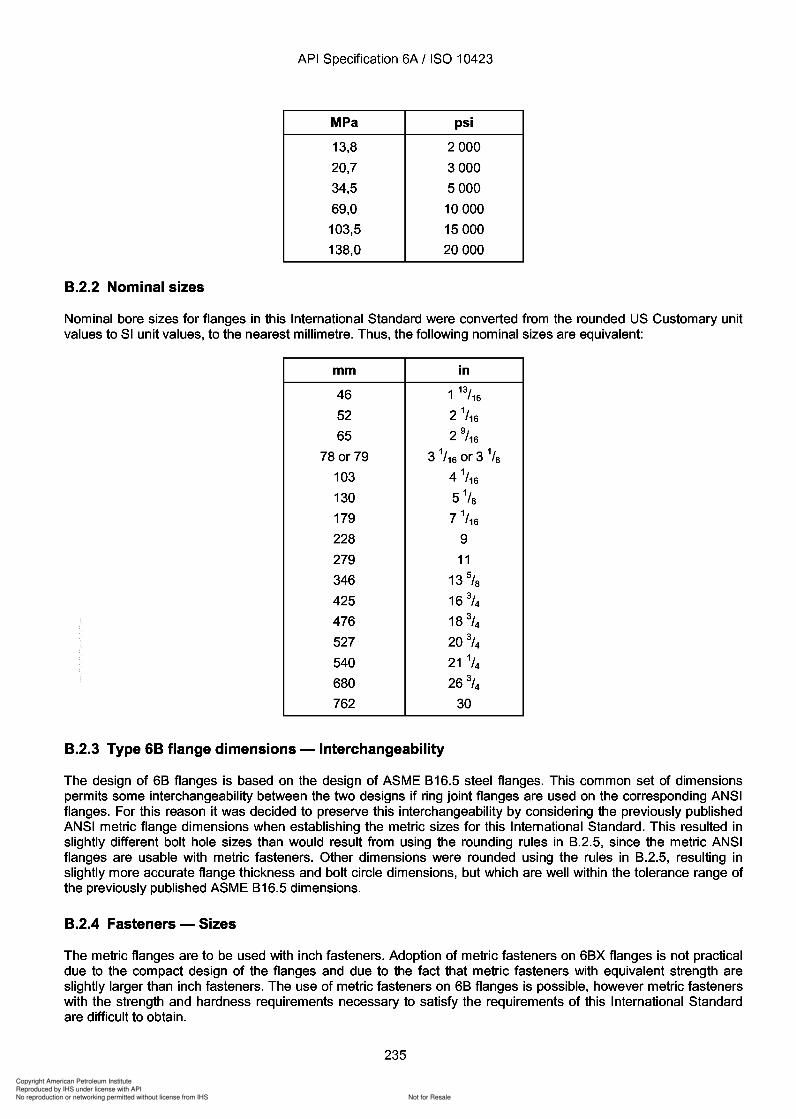
Copyright American Petroleum Institute
Reproduced by IHS under license with API
Not for ResaleNo reproduction or networking permitted without license from IHS
--`,,`,`,-`-`,,`,,`,`,,`---
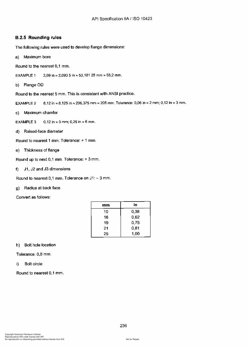
Copyright American Petroleum Institute
Reproduced by IHS under license with API
Not for ResaleNo reproduction or networking permitted without license from IHS
--`,,`,`,-`-`,,`,,`,`,,`---
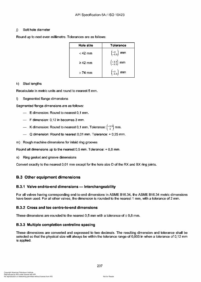
Copyright American Petroleum Institute
Reproduced by IHS under license with API
Not for ResaleNo reproduction or networking permitted without license from IHS
--`,,`,`,-`-`,,`,,`,`,,`---
Copyright American Petroleum Institute
Reproduced by IHS under license with API
Not for ResaleNo reproduction or networking permitted without license from IHS
--`,,`,`,-`-`,,`,,`,`,,`---
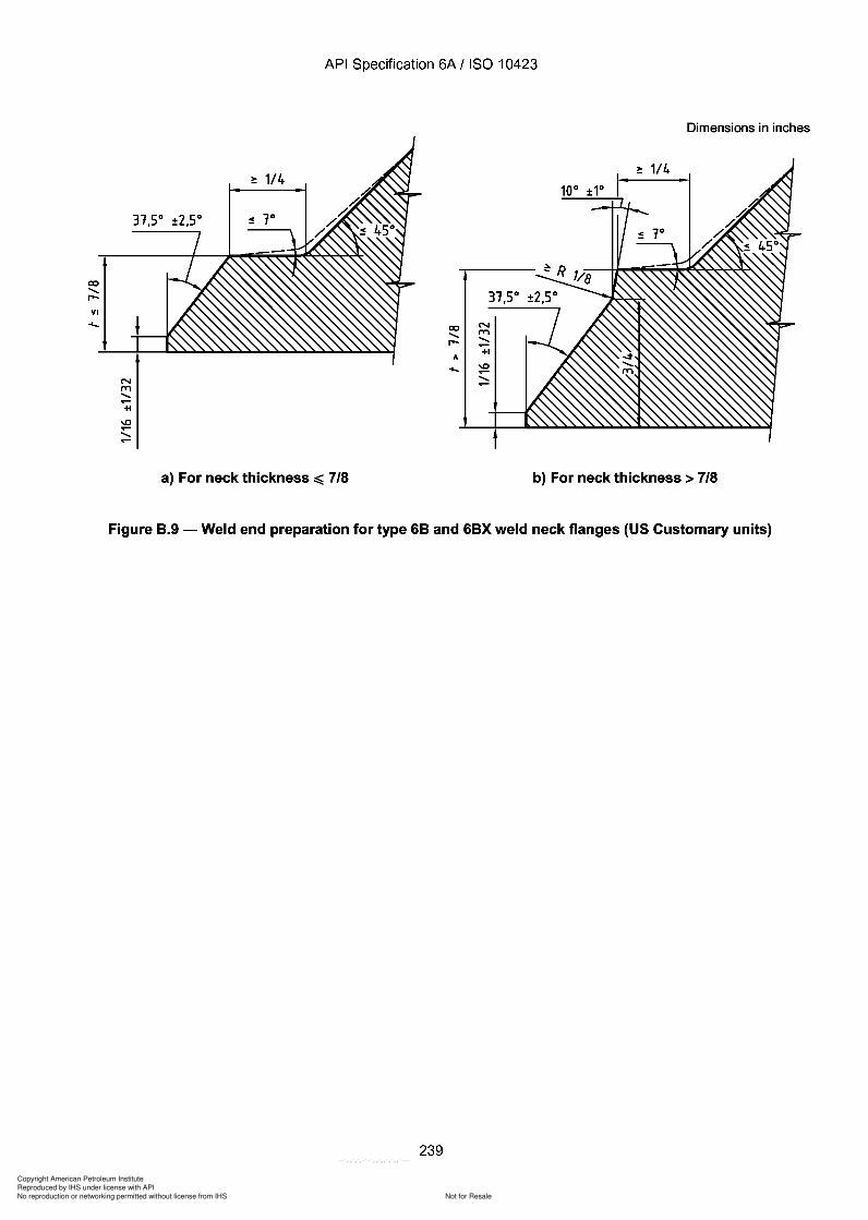
Copyright American Petroleum Institute
Reproduced by IHS under license with API
Not for ResaleNo reproduction or networking permitted without license from IHS
--`,,`,`,-`-`,,`,,`,`,,`---
API Specification 6A / ISO 10423
Dimensions in inches
co.....r-VI....
31,5°
co N
..... (T'l
r- .....~
A+1
.... -.0~.....~
a) For neck thickness ~ 7/8 b) For neck thickness> 7/8
Figure B.9 - Weld end preparation for type 6B and 6BX weld neck flanges (US Customary units)
239
co ..... r-VI
API Specification 6A / ISO 10423
Dimensions in inches
31,5°
co N
..... (T'l
r- ..... ~
A +1
.... -.0 ~ ..... ~
a) For neck thickness ~ 7/8 b) For neck thickness> 7/8
Figure B.9 - Weld end preparation for type 6B and 6BX weld neck flanges (US Customary units)
239
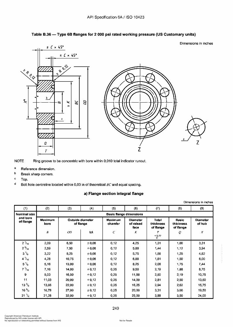
Copyright American Petroleum Institute
Reproduced by IHS under license with API
Not for ResaleNo reproduction or networking permitted without license from IHS
--`,,`,`,-`-`,,`,,`,`,,`---
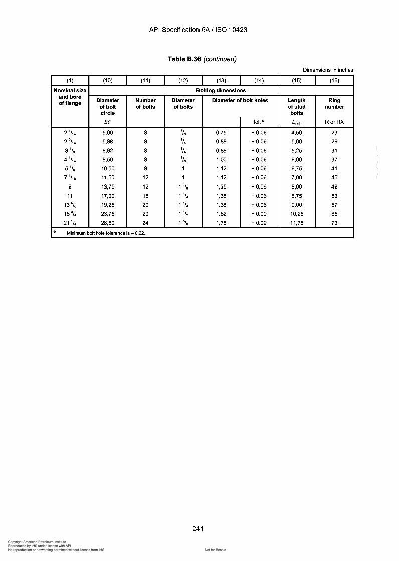
Copyright American Petroleum Institute
Reproduced by IHS under license with API
Not for ResaleNo reproduction or networking permitted without license from IHS
--`,,`,`,-`-`,,`,,`,`,,`---
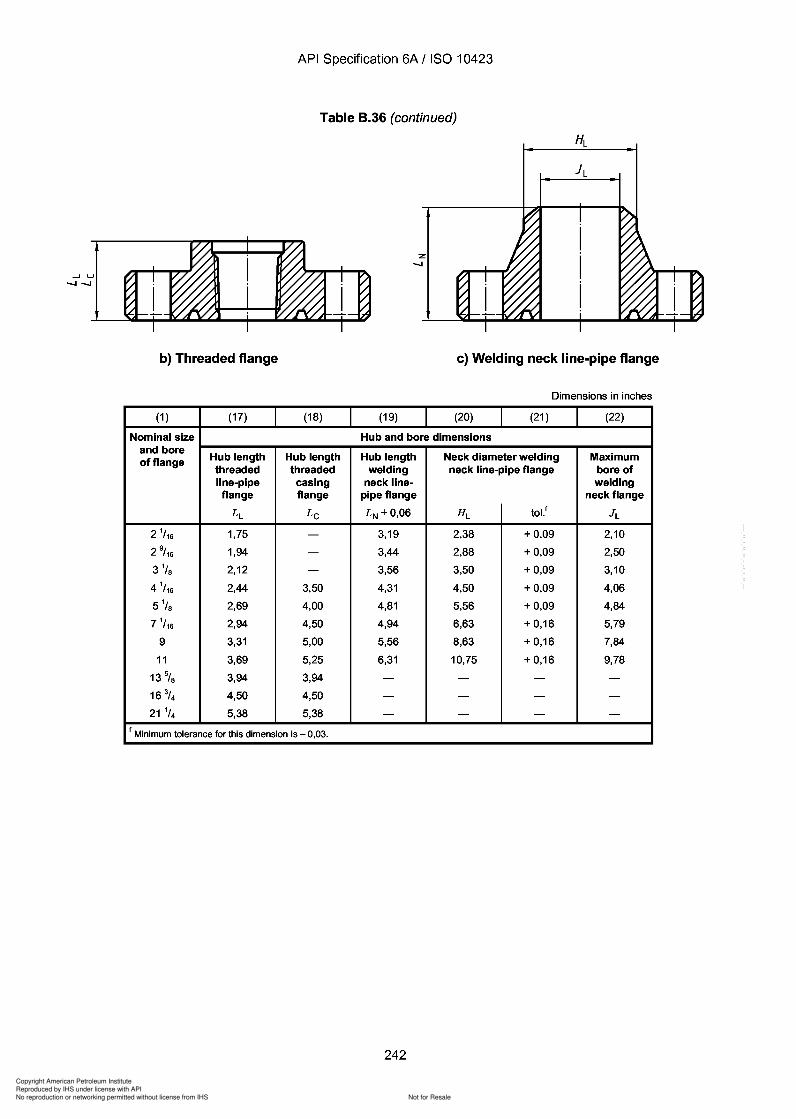
Copyright American Petroleum Institute
Reproduced by IHS under license with API
Not for ResaleNo reproduction or networking permitted without license from IHS
--`,,`,`,-`-`,,`,,`,`,,`---
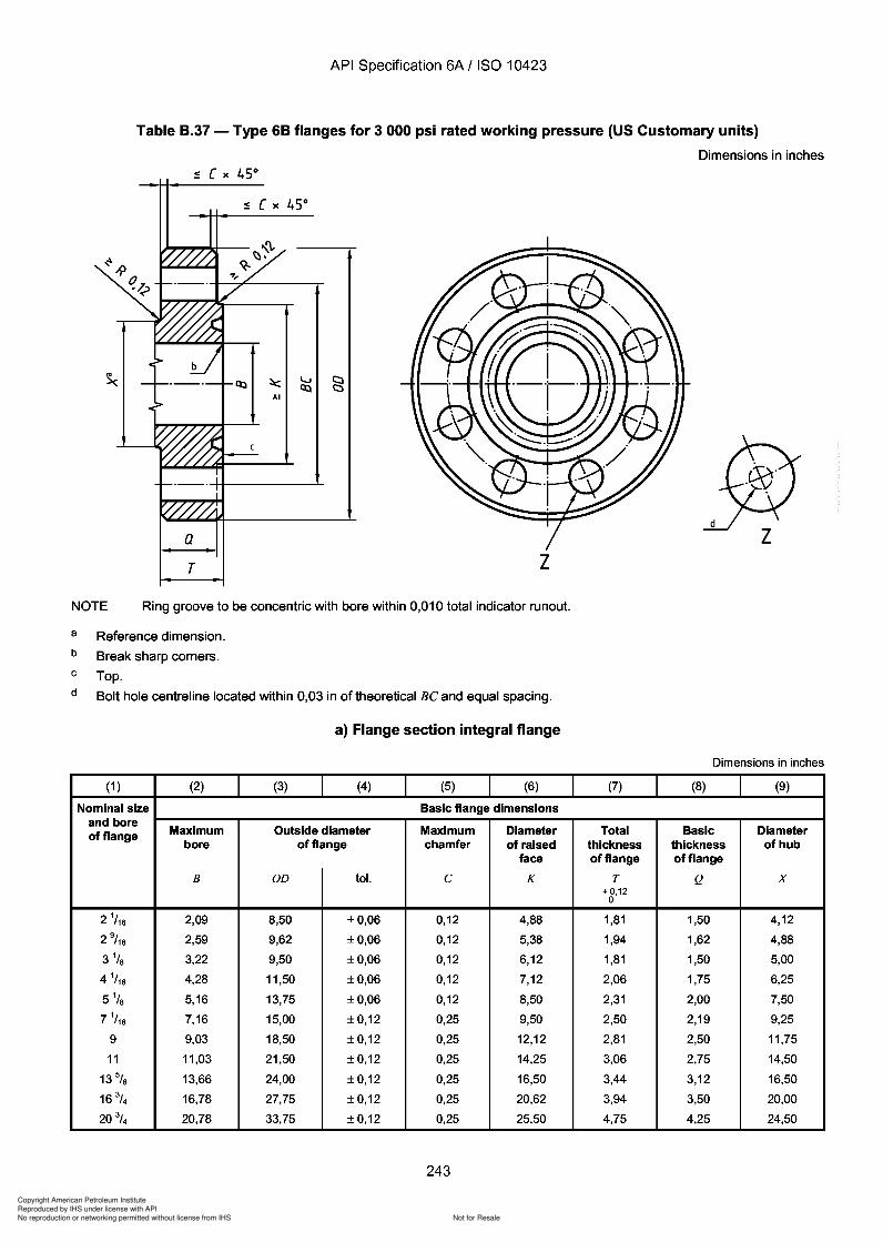
Copyright American Petroleum Institute
Reproduced by IHS under license with API
Not for ResaleNo reproduction or networking permitted without license from IHS
--`,,`,`,-`-`,,`,,`,`,,`---
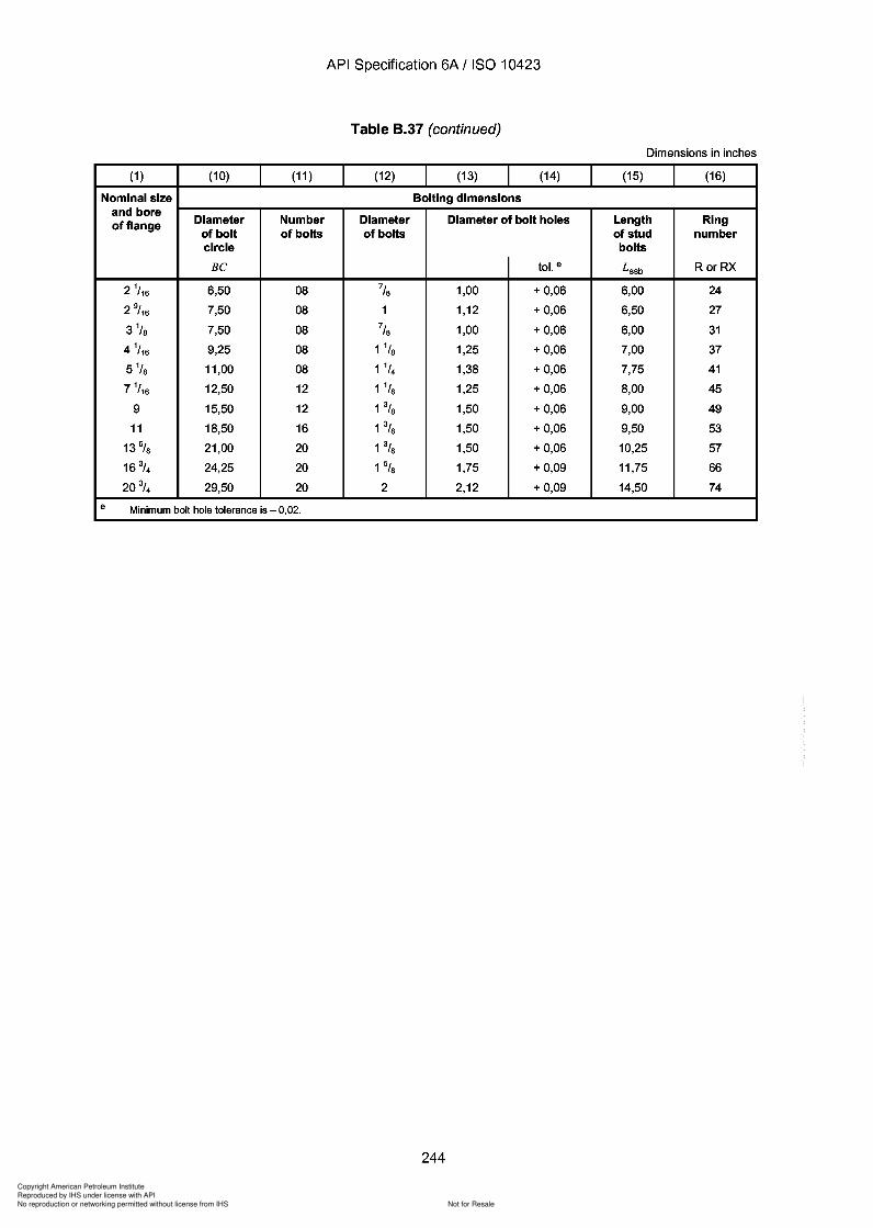
Copyright American Petroleum Institute
Reproduced by IHS under license with API
Not for ResaleNo reproduction or networking permitted without license from IHS
--`,,`,`,-`-`,,`,,`,`,,`---
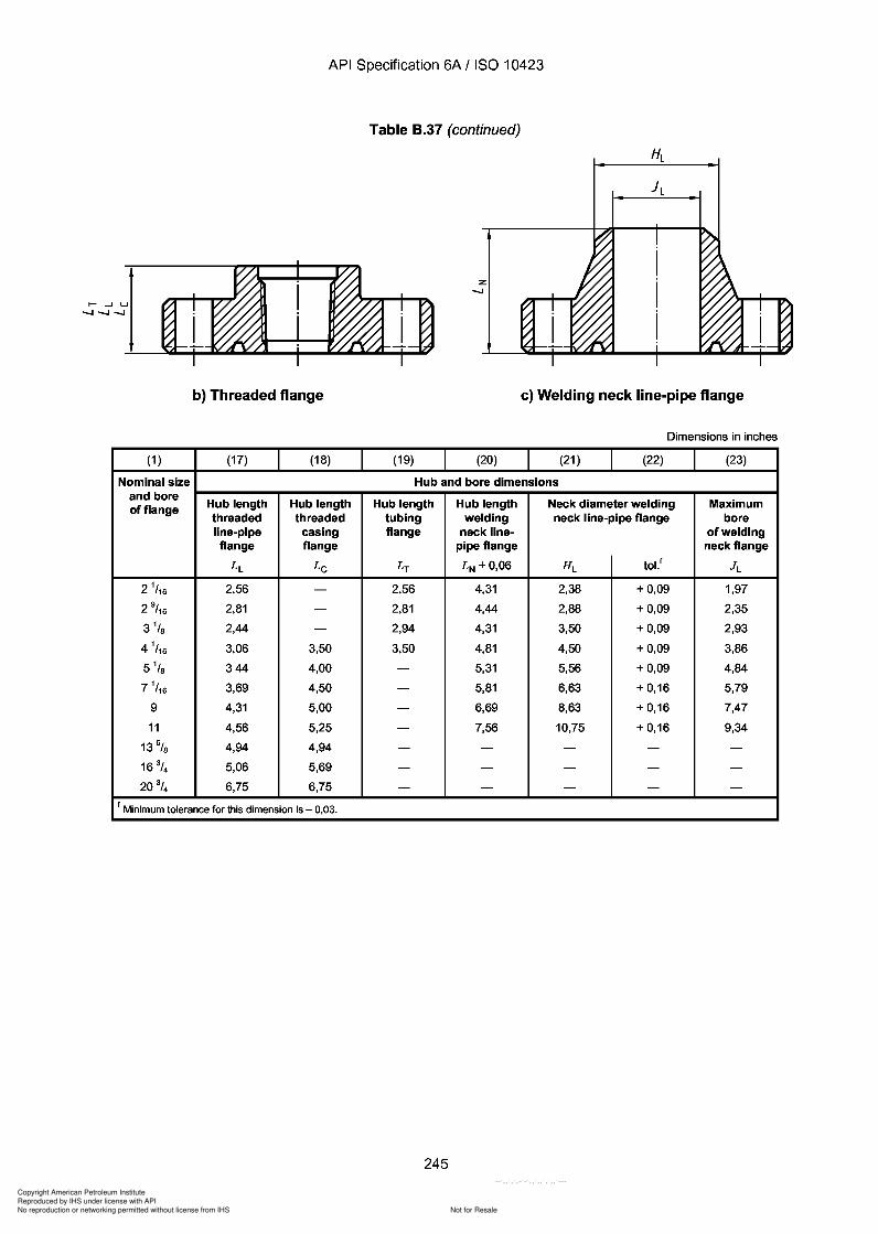
Copyright American Petroleum Institute
Reproduced by IHS under license with API
Not for ResaleNo reproduction or networking permitted without license from IHS
--`,,`,`,-`-`,,`,,`,`,,`---
API Specification 6A / ISO 10423
Table 8.37 (continued)
Z-.....I
b) Threaded flange c) Welding neck line-pipe flange
Dimensions in inches
(1 ) (17) (18) (19) (20) (21) (22) (23)
Nominal size Hub and bore dimensionsand bore
Hub length Hub length Hub length Hub length Neck diameter welding Maximumof flangethreaded threaded tubing welding neck line-pipe flange boreline-pipe casing flange neck line- of weldingflange flange pipe flange neck flange
LL Lc LT LN±0,06 HL tol.l JL
2 1/ 16 2,56 - 2,56 4,31 2,38 + 0,09 1,97
2 9/ 16 2,81 - 2,81 4,44 2,88 + 0,09 2,35
3 1/S 2,44 - 2,94 4,31 3,50 + 0,09 2,93
4 1/ 16 3,06 3,50 3,50 4,81 4,50 + 0,09 3,86
5 1/s 344 4,00 - 5,31 5,56 + 0,09 4,84
7 1/ 16 3,69 4,50 - 5,81 6,63 + 0,16 5,79
9 4,31 5,00 - 6,69 8,63 + 0,16 7,47
11 4,56 5,25 - 7,56 10,75 + 0,16 9,34
13 5/S 4,94 4,94 - - - - -
16 3/4 5,06 5,69 - - - - -
20 3/4 6,75 6,75 - - - - -
I Minimum tolerance for this dimension is - 0,03.
245
API Specification 6A / ISO 10423
b) Threaded flange
(1 ) (17) (18)
Nominal size and bore
Hub length Hub length of flange threaded threaded line-pipe casing flange flange
LL Lc
2 1/ 16 2,56 -
2 9/ 16 2,81 -
3 1/8 2,44 -
4 1/ 16 3,06 3,50
5 1/8 344 4,00
7 1/ 16 3,69 4,50
9 4,31 5,00
11 4,56 5,25
13 5/8 4,94 4,94
16 3/4 5,06 5,69
20 3/4 6,75 6,75
I Minimum tolerance for this dimension is - 0,03.
Table 8.37 (continued)
(19)
Z -.....I
(20)
c) Welding neck line-pipe flange
Dimensions in inches
(21) (22) (23)
Hub and bore dimensions
Hub length Hub length Neck diameter welding Maximum tubing welding neck line-pipe flange bore flange neck line- of welding
pipe flange neck flange
LT LN ±0,06 HL toLl JL
2,56 4,31 2,38 + 0,09 1,97
2,81 4,44 2,88 + 0,09 2,35
2,94 4,31 3,50 + 0,09 2,93
3,50 4,81 4,50 + 0,09 3,86
- 5,31 5,56 + 0,09 4,84
- 5,81 6,63 + 0,16 5,79
- 6,69 8,63 + 0,16 7,47
- 7,56 10,75 + 0,16 9,34
- - - - -
- - - - -
- - - - -
245
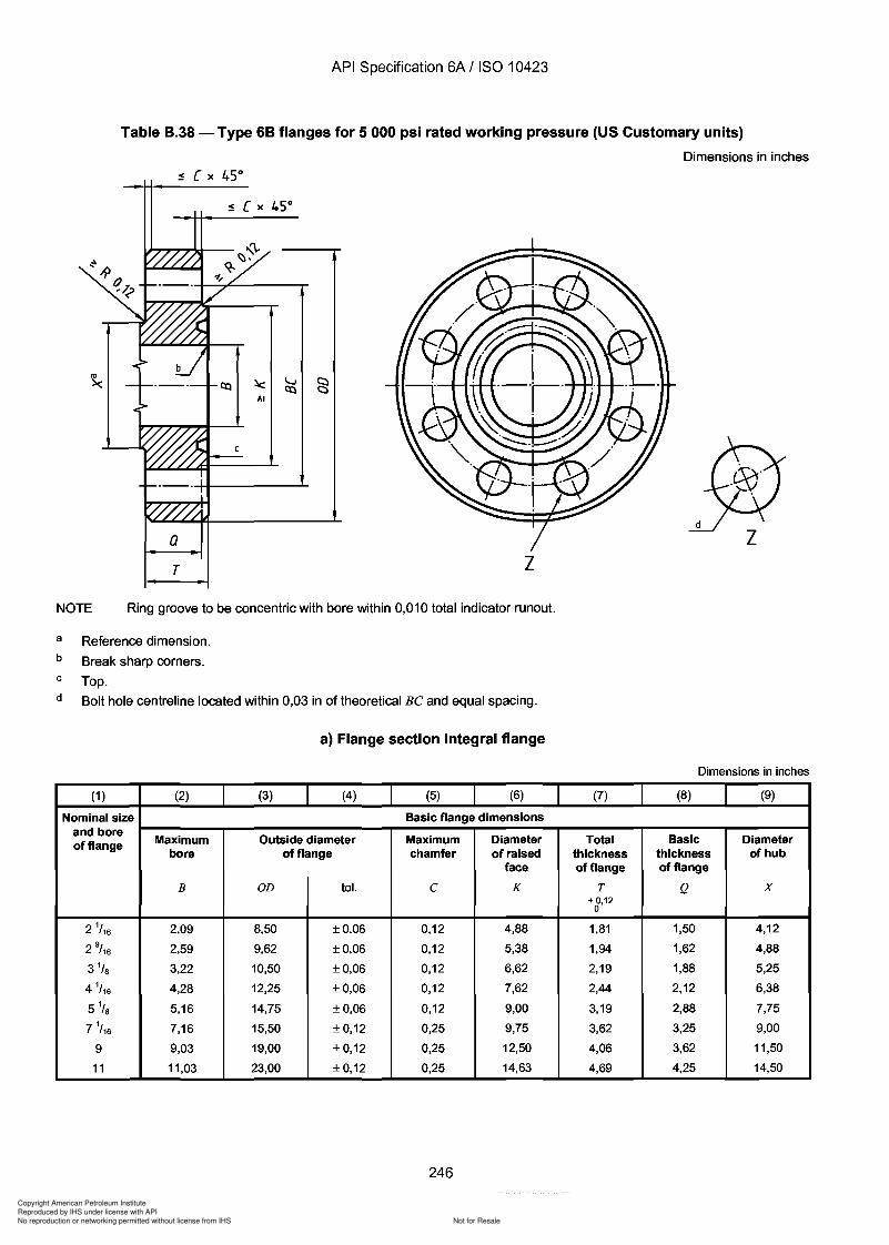
Copyright American Petroleum Institute
Reproduced by IHS under license with API
Not for ResaleNo reproduction or networking permitted without license from IHS
--`,,`,`,-`-`,,`,,`,`,,`---
API Specification 6A / ISO 10423
Table 8.38 - Type 68 flanges for 5 000 psi rated working pressure (US Customary units)
Dimensions in inches
aT z
NOTE Ring groove to be concentric with bore within 0,010 total indicator runout.
a
b
c
d
Reference dimension.
Break sharp corners.
Top.
Bolt hole centreline located within 0,03 in of theoretical Be and equal spacing.
a) Flange section integral flange
Dimensions in inches
(1 ) (2) (3) (4) (5) (6) (7) (8) (9)
Nominal size Basic flange dimensionsand bore
Maximum Outside diameter Maximum Diameter Total Basic Diameterof flangebore of flange chamfer of raised thickness thickness of hub
face of flange of flange
B OD tol. e K T Q X+ 0,12
0
2 1/ 16 2,09 8,50 ±0,06 0,12 4,88 1,81 1,50 4,12
2 9/ 16 2,59 9,62 ±0,06 0,12 5,38 1,94 1,62 4,88
3 1/ S 3,22 10,50 ±0,06 0,12 6,62 2,19 1,88 5,25
4 1/ 16 4,28 12,25 ±0,06 0,12 7,62 2,44 2,12 6,38
5 1/s 5,16 14,75 ±0,06 0,12 9,00 3,19 2,88 7,75
7 1/ 16 7,16 15,50 ±0,12 0,25 9,75 3,62 3,25 9,00
9 9,03 19,00 ±0,12 0,25 12,50 4,06 3,62 11,50
11 11,03 23,00 ±0,12 0,25 14,63 4,69 4,25 14,50
246
API Specification 6A / ISO 10423
Table B.38 - Type 6B flanges for 5 000 psi rated working pressure (US Customary units)
Dimensions in inches
a T z
NOTE Ring groove to be concentric with bore within 0,010 total indicator runout.
a
b
c
d
Reference dimension.
Break sharp corners.
Top.
Bolt hole centreline located within 0,03 in of theoretical Be and equal spacing.
a) Flange section integral flange
(1 ) (2) (3) (4) (5) (6)
Nominal size Basic flange dimensions and bore
Maximum Outside diameter Maximum Diameter of flange bore of flange chamfer of raised
face
B OD tol. C K
2 1/ 16 2,09 8,50 ±0,06 0,12 4,88
2 9/ 16 2,59 9,62 ±0,06 0,12 5,38
3 1/ 8 3,22 10,50 ±0,06 0,12 6,62
4 1/ 16 4,28 12,25 ±0,06 0,12 7,62
5 1/8 5,16 14,75 ±0,06 0,12 9,00
7 1/ 16 7,16 15,50 ±0,12 0,25 9,75
9 9,03 19,00 ±0,12 0,25 12,50
11 11,03 23,00 ±0,12 0,25 14,63
246
Dimensions in inches
(7) (8) (9)
Total Basic Diameter thickness thickness of hub of flange of flange
T Q X + 0,12
0
1,81 1,50 4,12
1,94 1,62 4,88
2,19 1,88 5,25
2,44 2,12 6,38
3,19 2,88 7,75
3,62 3,25 9,00
4,06 3,62 11,50
4,69 4,25 14,50
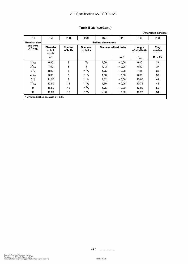
Copyright American Petroleum Institute
Reproduced by IHS under license with API
Not for ResaleNo reproduction or networking permitted without license from IHS
--`,,`,`,-`-`,,`,,`,`,,`---
API Specification 6A / ISO 10423
Table 8.38 (continued)
Dimensions in inches
(1 ) (10) (11 ) (12) (13) (14) (15) (16)
Nominal size Bolting dimensionsand bore
Diameter Number Diameter Diameter of bolt holes Length Ringof flangeof bolt of bolts of bolts of stud bolts numbercircle
Be tol. e L ssb RorRX
2 1/ 16 6,50 8 7/S 1,00 + 0,06 6,00 24
2 9/ 16 7,50 8 1 1,12 + 0,06 6,50 27
3 1/S 8,00 8 1 1/S 1,25 + 0,06 7,25 35
4 1/ 16 9,50 8 1 1/4 1,38 + 0,06 8,00 39
5 1/s 11,50 8 1 1/2 1,62 + 0,06 10,00 44
7 1/ 16 12,50 12 1% 1,50 + 0,06 10,75 46
9 15,50 12 1% 1,75 + 0,09 12,00 50
11 19,00 12 1 7/S 2,00 + 0,09 13,75 54
e Minimum bolt hole tolerance is - 0,02.
247
API Specification 6A / ISO 10423
Table B.38 (continued)
Dimensions in inches
(1 ) (10) (11 ) (12) (13) (14) (15) (16)
Nominal size Bolting dimensions and bore
Diameter Number Diameter Diameter of bolt holes Length Ring of flange of bolt of bolts of bolts of stud bolts number circle
Be tol. e Lssb RorRX
2 1/ 16 6,50 8 7/S 1,00 + 0,06 6,00 24
2 9/ 16 7,50 8 1 1,12 + 0,06 6,50 27
3 1/S 8,00 8 1 1/S 1,25 + 0,06 7,25 35
4 1/ 16 9,50 8 1 1/4 1,38 + 0,06 8,00 39
5 1/s 11,50 8 1 1/2 1,62 + 0,06 10,00 44
7 1/ 16 12,50 12 1% 1,50 + 0,06 10,75 46
9 15,50 12 1% 1,75 + 0,09 12,00 50
11 19,00 12 1 7/S 2,00 + 0,09 13,75 54
e Minimum bolt hole tolerance is - 0,02.
247
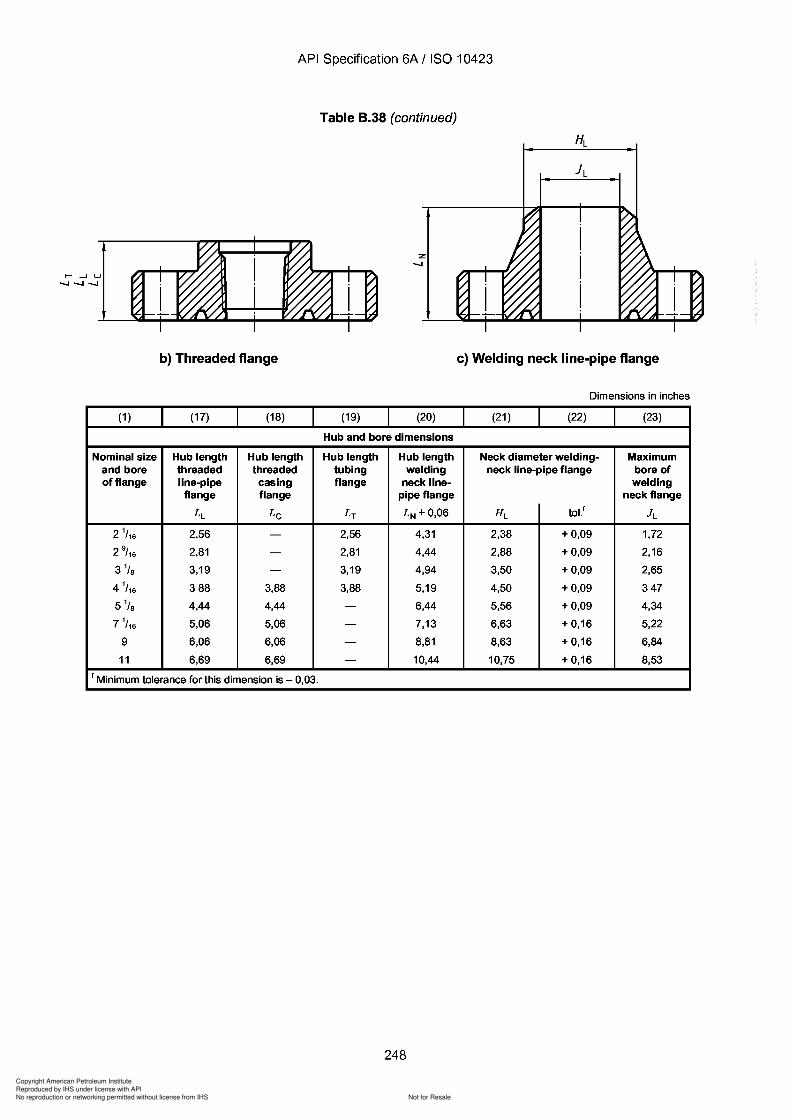
Copyright American Petroleum Institute
Reproduced by IHS under license with API
Not for ResaleNo reproduction or networking permitted without license from IHS
--`,,`,`,-`-`,,`,,`,`,,`---
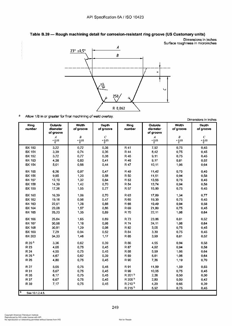
Copyright American Petroleum Institute
Reproduced by IHS under license with API
Not for ResaleNo reproduction or networking permitted without license from IHS
--`,,`,`,-`-`,,`,,`,`,,`---
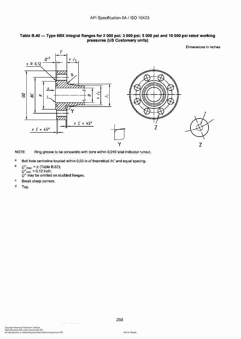
Copyright American Petroleum Institute
Reproduced by IHS under license with API
Not for ResaleNo reproduction or networking permitted without license from IHS
--`,,`,`,-`-`,,`,,`,`,,`---
API Specification 6A / ISO 10423
Table B.40 - Type 6BX integral flanges for 2000 psi; 3000 psi; 5000 psi and 10000 psi rated workingpressures (US Customary units)
Dimensions in inches
T
:!: R 0,12
N....,AI
....,
by
z
zNOTE Ring groove to be concentric with bore within 0,010 total indicator runout.
a
b
c
d
Bolt hole centreline located within 0,03 in of theoretical Be and equal spacing.
Q"max. = E (Table B.52);Q"min. = 0,12 inch;Q" may be omitted on studded flanges.
Break sharp corners.
Top.
250
API Specification 6A / ISO 10423
Table B.40 - Type 6BX integral flanges for 2000 psi; 3000 psi; 5000 psi and 10000 psi rated working pressures (US Customary units)
Dimensions in inches
T
:!: R 0,12
N
....... AI
b z
y z NOTE Ring groove to be concentric with bore within 0,010 total indicator runout.
a
b
c
d
Bolt hole centreline located within 0,03 in of theoretical Be and equal spacing.
Q" max. = E (Table B.52); Q" min. = 0,12 inch; Q" may be omitted on studded flanges.
Break sharp corners.
Top.
250
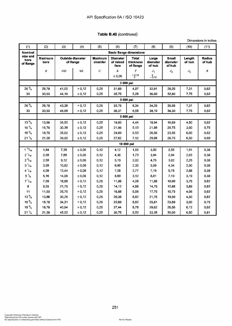
Copyright American Petroleum Institute
Reproduced by IHS under license with API
Not for ResaleNo reproduction or networking permitted without license from IHS
--`,,`,`,-`-`,,`,,`,`,,`---
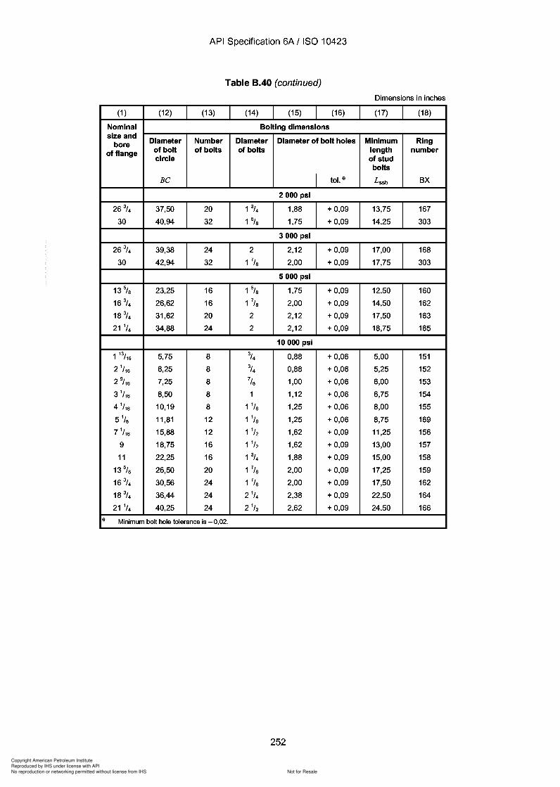
Copyright American Petroleum Institute
Reproduced by IHS under license with API
Not for ResaleNo reproduction or networking permitted without license from IHS
--`,,`,`,-`-`,,`,,`,`,,`---
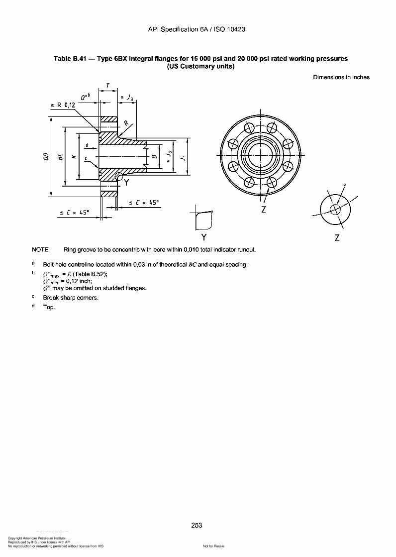
Copyright American Petroleum Institute
Reproduced by IHS under license with API
Not for ResaleNo reproduction or networking permitted without license from IHS
--`,,`,`,-`-`,,`,,`,`,,`---
API Specification 6A / ISO 10423
Table B.41 - Type 6BX integral flanges for 15 000 psi and 20 000 psi rated working pressures(US Customary units)
Dimensions in inches
T
~ R 0,12
N......,
AI
by
z
z
a
NOTE Ring groove to be concentric with bore within 0,010 total indicator runout.
a
b
c
d
Bolt hole centreline located within 0,03 in of theoretical Be and equal spacing.
Q"max. = E (Table B.52);Q"min. = 0,12 inch;Q" may be omitted on studded flanges.
Break sharp corners.
Top.
253
API Specification 6A / ISO 10423
Table B.41 - Type 6BX integral flanges for 15 000 psi and 20 000 psi rated working pressures (US Customary units)
Dimensions in inches
T
~ R 0,12
N ......,
AI
a
b z
y z NOTE Ring groove to be concentric with bore within 0,010 total indicator runout.
a
b
c
d
Bolt hole centreline located within 0,03 in of theoretical Be and equal spacing.
Q" max. = E (Table B.52); Q" min. = 0,12 inch; Q" may be omitted on studded flanges.
Break sharp corners.
Top.
253
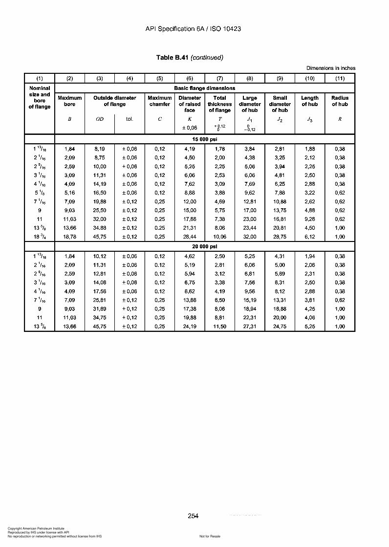
Copyright American Petroleum Institute
Reproduced by IHS under license with API
Not for ResaleNo reproduction or networking permitted without license from IHS
--`,,`,`,-`-`,,`,,`,`,,`---
API Specification 6A / ISO 10423
Table 8.41 (continued)
Dimensions in inches
(1 ) (2) (3) (4) (5) (6) (7) (8) (9) (10) (11 )
Nominal Basic flange dimensionssize and
Maximum Outside diameter Maximum Diameter Total Large Small Length Radiusboreof flange bore of flange chamfer of raised thickness diameter diameter of hub of hub
face of flange of hub of hub
B OD tol. C K T J 1 J2 J 3 R
±0,06 +0,12 00 -0,12
15000 psi
1 13/16 1,84 8,19 ±0,06 0,12 4,19 1,78 3,84 2,81 1,88 0,38
2 1/ 16 2,09 8,75 ±0,06 0,12 4,50 2,00 4,38 3,25 2,12 0,38
2 9/ 16 2,59 10,00 ±0,06 0,12 5,25 2,25 5,06 3,94 2,25 0,38
3 1/ 16 3,09 11,31 ±0,06 0,12 6,06 2,53 6,06 4,81 2,50 0,38
4 1/ 16 4,09 14,19 ±0,06 0,12 7,62 3,09 7,69 6,25 2,88 0,38
5 1/s 5,16 16,50 ±0,06 0,12 8,88 3,88 9,62 7,88 3,22 0,62
7 1/ 16 7,09 19,88 ±0,12 0,25 12,00 4,69 12,81 10,88 2,62 0,62
9 9,03 25,50 ±0,12 0,25 15,00 5,75 17,00 13,75 4,88 0,62
11 11,03 32,00 ±0,12 0,25 17,88 7,38 23,00 16,81 9,28 0,62
13% 13,66 34,88 ±0,12 0,25 21,31 8,06 23,44 20,81 4,50 1,00
18 3/4 18,78 45,75 ±0,12 0,25 28,44 10,06 32,00 28,75 6,12 1,00
20000 psi
1 13/16 1,84 10,12 ±0,06 0,12 4,62 2,50 5,25 4,31 1,94 0,38
2 1/ 16 2,09 11,31 ±0,06 0,12 5,19 2,81 6,06 5,00 2,06 0,38
2 9/ 16 2,59 12,81 ±0,06 0,12 5,94 3,12 6,81 5,69 2,31 0,38
3 1/ 16 3,09 14,06 ±0,06 0,12 6,75 3,38 7,56 6,31 2,50 0,38
4 1/ 16 4,09 17,56 ±0,06 0,12 8,62 4,19 9,56 8,12 2,88 0,38
7 1/ 16 7,09 25,81 ±0,12 0,25 13,88 6,50 15,19 13,31 3,81 0,62
9 9,03 31,69 ±0,12 0,25 17,38 8,06 18,94 16,88 4,25 1,00
11 11,03 34,75 ±0,12 0,25 19,88 8,81 22,31 20,00 4,06 1,00
13 5/S 13,66 45,75 ±0,12 0,25 24,19 11,50 27,31 24,75 5,25 1,00
254
API Specification 6A / ISO 10423
Table 8.41 (continued)
Dimensions in inches
(1 ) (2) (3) (4) (5) (6) (7) (8) (9) (10) (11 )
Nominal Basic flange dimensions size and
Maximum Outside diameter Maximum Diameter Total Large Small Length Radius bore of flange bore of flange chamfer of raised thickness diameter diameter of hub of hub
face of flange of hub of hub
B OD tol. C K T J 1 J2 J 3 R
±0,06 +0,12 0 0 -0,12
15000 psi
1 13/16 1,84 8,19 ±0,06 0,12 4,19 1,78 3,84 2,81 1,88 0,38
2 1/ 16 2,09 8,75 ±0,06 0,12 4,50 2,00 4,38 3,25 2,12 0,38
2 9/ 16 2,59 10,00 ±0,06 0,12 5,25 2,25 5,06 3,94 2,25 0,38
3 1/ 16 3,09 11,31 ±0,06 0,12 6,06 2,53 6,06 4,81 2,50 0,38
4 1/ 16 4,09 14,19 ±0,06 0,12 7,62 3,09 7,69 6,25 2,88 0,38
5 1/8 5,16 16,50 ±0,06 0,12 8,88 3,88 9,62 7,88 3,22 0,62
7 1/ 16 7,09 19,88 ±0,12 0,25 12,00 4,69 12,81 10,88 2,62 0,62
9 9,03 25,50 ±0,12 0,25 15,00 5,75 17,00 13,75 4,88 0,62
11 11,03 32,00 ±0,12 0,25 17,88 7,38 23,00 16,81 9,28 0,62
13% 13,66 34,88 ±0,12 0,25 21,31 8,06 23,44 20,81 4,50 1,00
18 3/4 18,78 45,75 ±0,12 0,25 28,44 10,06 32,00 28,75 6,12 1,00
20000 psi
1 13/16 1,84 10,12 ±0,06 0,12 4,62 2,50 5,25 4,31 1,94 0,38
2 1/ 16 2,09 11,31 ±0,06 0,12 5,19 2,81 6,06 5,00 2,06 0,38
2 9/ 16 2,59 12,81 ±0,06 0,12 5,94 3,12 6,81 5,69 2,31 0,38
3 1/ 16 3,09 14,06 ±0,06 0,12 6,75 3,38 7,56 6,31 2,50 0,38
4 1/ 16 4,09 17,56 ±0,06 0,12 8,62 4,19 9,56 8,12 2,88 0,38
7 1/ 16 7,09 25,81 ±0,12 0,25 13,88 6,50 15,19 13,31 3,81 0,62
9 9,03 31,69 ±0,12 0,25 17,38 8,06 18,94 16,88 4,25 1,00
11 11,03 34,75 ±0,12 0,25 19,88 8,81 22,31 20,00 4,06 1,00
13 5/8 13,66 45,75 ±0,12 0,25 24,19 11,50 27,31 24,75 5,25 1,00
254
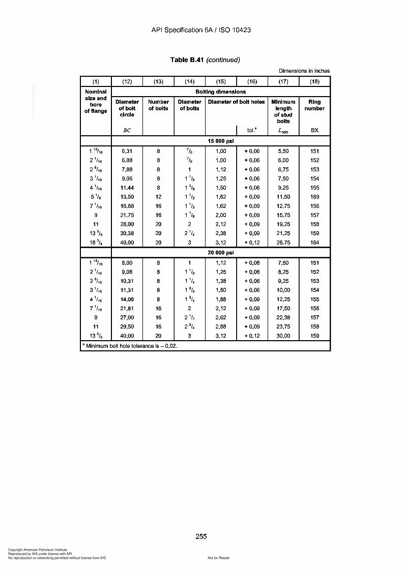
Copyright American Petroleum Institute
Reproduced by IHS under license with API
Not for ResaleNo reproduction or networking permitted without license from IHS
--`,,`,`,-`-`,,`,,`,`,,`---
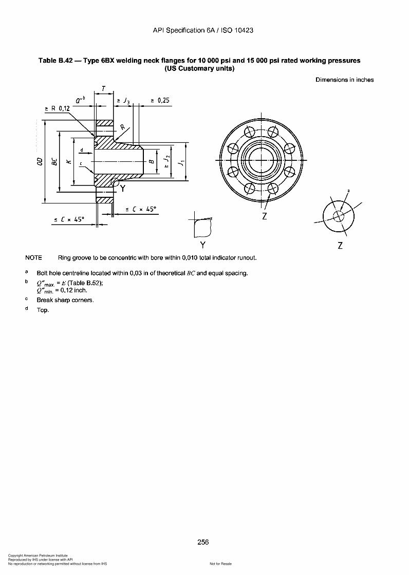
Copyright American Petroleum Institute
Reproduced by IHS under license with API
Not for ResaleNo reproduction or networking permitted without license from IHS
--`,,`,`,-`-`,,`,,`,`,,`---
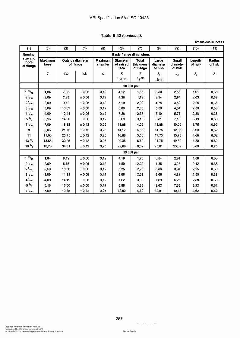
Copyright American Petroleum Institute
Reproduced by IHS under license with API
Not for ResaleNo reproduction or networking permitted without license from IHS
--`,,`,`,-`-`,,`,,`,`,,`---
API Specification 6A / ISO 10423
Table 8.42 (continued)
Dimensions in inches
(1 ) (2) (3) (4) (5) (6) (7) (8) (9) (10) (11 )
Nominal Basic flange dimensionssize and
Maximum Outside diameter Maximum Diameter Total Large Small Length Radiusboreof flange bore of flange chamfer of raised thickness diameter diameter of hub of hub
face of flange of hub of hub
B OD tol. C K T J 1 J2 J 3 R
±0,06 + 0,12 00 -0,12
10000 psi
1 13/16 1,84 7,38 ±0,06 0,12 4,12 1,66 3,50 2,56 1,91 0,38
2 1/ 16 2,09 7,88 ±0,06 0,12 4,38 1,73 3,94 2,94 2,03 0,38
2 9/ 16 2,59 9,12 ±0,06 0,12 5,19 2,02 4,75 3,62 2,25 0,38
3 1/ 16 3,09 10,62 ±0,06 0,12 6,00 2,30 5,59 4,34 2,50 0,38
4 1/ 16 4,09 12,44 ±0,06 0,12 7,28 2,77 7,19 5,75 2,88 0,38
5 1/s 5,16 14,06 ±0,06 0,12 8,69 3,13 8,81 7,19 3,19 0,38
7 1/ 16 7,09 18,88 ±0,12 0,25 11,88 4,06 11,88 10,00 3,75 0,62
9 9,03 21,75 ±0,12 0,25 14,12 4,88 14,75 12,88 3,69 0,62
11 11,03 25,75 ±0,12 0,25 16,88 5,56 17,75 15,75 4,06 0,62
13% 13,66 30,25 ±0,12 0,25 20,38 6,62 21,75 19,50 4,50 0,62
16 3/ 4 16,78 34,31 ±0,12 0,25 22,69 6,62 25,81 23,69 3,00 0,75
15000 psi
1 13/16 1,84 8,19 ±0,06 0,12 4,19 1,78 3,84 2,81 1,88 0,38
2 1/ 16 2,09 8,75 ±0,06 0,12 4,50 2,00 4,38 3,25 2,12 0,38
2 9/ 16 2,59 10,00 ±0,06 0,12 5,25 2,25 5,06 3,94 2,25 0,38
3 1/ 16 3,09 11,31 ±0,06 0,12 6,06 2,53 6,06 4,81 2,50 0,38
4 1/ 16 4,09 14,19 ±0,06 0,12 7,62 3,09 7,69 6,25 2,88 0,38
5 1/s 5,16 16,50 ±0,06 0,12 8,88 3,88 9,62 7,88 3,22 0,62
7 1/ 16 7,09 19,88 ±0,12 0,25 12,00 4,69 12,81 10,88 3,62 0,62
257
API Specification 6A / ISO 10423
Table 8.42 (continued)
Dimensions in inches
(1 ) (2) (3) (4) (5) (6) (7) (8) (9) (10) (11 )
Nominal Basic flange dimensions size and
Maximum Outside diameter Maximum Diameter Total Large Small Length Radius bore of flange bore of flange chamfer of raised thickness diameter diameter of hub of hub
face of flange of hub of hub
B OD tol. C K T J 1 J2 J 3 R
±0,06 + 0,12 0 0 -0,12
10000 psi
1 13/16 1,84 7,38 ±0,06 0,12 4,12 1,66 3,50 2,56 1,91 0,38
2 1/ 16 2,09 7,88 ±0,06 0,12 4,38 1,73 3,94 2,94 2,03 0,38
2 9/ 16 2,59 9,12 ±0,06 0,12 5,19 2,02 4,75 3,62 2,25 0,38
3 1/ 16 3,09 10,62 ±0,06 0,12 6,00 2,30 5,59 4,34 2,50 0,38
4 1/ 16 4,09 12,44 ±0,06 0,12 7,28 2,77 7,19 5,75 2,88 0,38
5 1/8 5,16 14,06 ±0,06 0,12 8,69 3,13 8,81 7,19 3,19 0,38
7 1/ 16 7,09 18,88 ±0,12 0,25 11,88 4,06 11,88 10,00 3,75 0,62
9 9,03 21,75 ±0,12 0,25 14,12 4,88 14,75 12,88 3,69 0,62
11 11,03 25,75 ±0,12 0,25 16,88 5,56 17,75 15,75 4,06 0,62
13% 13,66 30,25 ±0,12 0,25 20,38 6,62 21,75 19,50 4,50 0,62
16 3/ 4 16,78 34,31 ±0,12 0,25 22,69 6,62 25,81 23,69 3,00 0,75
15000 psi
1 13/16 1,84 8,19 ±0,06 0,12 4,19 1,78 3,84 2,81 1,88 0,38
2 1/ 16 2,09 8,75 ±0,06 0,12 4,50 2,00 4,38 3,25 2,12 0,38
2 9/ 16 2,59 10,00 ±0,06 0,12 5,25 2,25 5,06 3,94 2,25 0,38
3 1/ 16 3,09 11,31 ±0,06 0,12 6,06 2,53 6,06 4,81 2,50 0,38
4 1/ 16 4,09 14,19 ±0,06 0,12 7,62 3,09 7,69 6,25 2,88 0,38
5 1/8 5,16 16,50 ±0,06 0,12 8,88 3,88 9,62 7,88 3,22 0,62
7 1/ 16 7,09 19,88 ±0,12 0,25 12,00 4,69 12,81 10,88 3,62 0,62
257
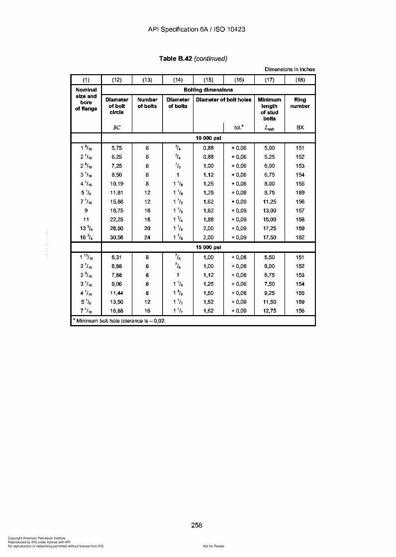
Copyright American Petroleum Institute
Reproduced by IHS under license with API
Not for ResaleNo reproduction or networking permitted without license from IHS
--`,,`,`,-`-`,,`,,`,`,,`---
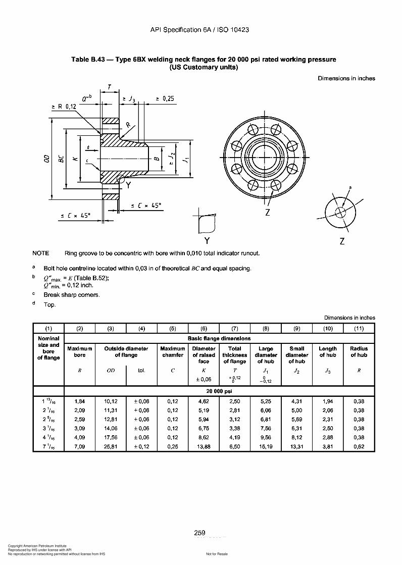
J3
Copyright American Petroleum Institute
Reproduced by IHS under license with API
Not for ResaleNo reproduction or networking permitted without license from IHS
--`,,`,`,-`-`,,`,,`,`,,`---
API Specification 6A / ISO 10423
Table B.43 - Type 6BX welding neck flanges for 20 000 psi rated working pressure(US Customary units)
Dimensions in inches
T
~ R 0,12~ 0,25
N......,
AI
by
z
a
zNOTE Ring groove to be concentric with bore within 0,010 total indicator runout.
a
b
c
d
Bolt hole centreline located within 0,03 in of theoretical Be and equal spacing.
Q"max. = E (Table B.52);Q"min. = 0,12 inch.
Break sharp corners.
Top.
Dimensions in inches
(1 ) (2) (3) (4) (5) (6) (7) (8) (9) (10) (11 )
Nominal Basic flange dimensionssize and
Maximum Outside diameter Maximum Diameter Total Large Small Length Radiusboreof flange bore of flange chamfer of raised thickness diameter diameter of hub of hub
face of flange of hub of hub
B OD tol. e K T J 1 J2 J 3 R
±0,06 + 0,12 00 -0,12
20000 psi
1 13/16 1,84 10,12 ±0,06 0,12 4,62 2,50 5,25 4,31 1,94 0,38
2 1/ 16 2,09 11,31 ±0,06 0,12 5,19 2,81 6,06 5,00 2,06 0,38
2 9/ 16 2,59 12,81 ±0,06 0,12 5,94 3,12 6,81 5,69 2,31 0,38
3 1/ 16 3,09 14,06 ±0,06 0,12 6,75 3,38 7,56 6,31 2,50 0,38
4 1/ 16 4,09 17,56 ±0,06 0,12 8,62 4,19 9,56 8,12 2,88 0,38
7 1/ 16 7,09 25,81 ±0,12 0,25 13,88 6,50 15,19 13,31 3,81 0,62
259
API Specification 6A / ISO 10423
Table B.43 - Type 6BX welding neck flanges for 20 000 psi rated working pressure (US Customary units)
Dimensions in inches
T
~ 0,25 ~ R 0,12
N ......,
AI
a
b z
y z NOTE Ring groove to be concentric with bore within 0,010 total indicator runout.
a
b
c
d
Bolt hole centreline located within 0,03 in of theoretical Be and equal spacing.
Q" max. = E (Table B.52); Q" min. = 0,12 inch.
Break sharp corners.
Top.
(1 ) (2) (3) (4) (5) (6) (7)
Nominal Basic flange dimensions size and
Maximum Outside diameter Maximum Diameter Total bore of flange bore of flange chamfer of raised thickness
face of flange
B OD tol. C K T
±0,06 + 0,12 0
20000 psi
1 13/16 1,84 10,12 ±0,06 0,12 4,62 2,50
2 1/ 16 2,09 11,31 ±0,06 0,12 5,19 2,81
2 9/ 16 2,59 12,81 ±0,06 0,12 5,94 3,12
3 1/ 16 3,09 14,06 ±0,06 0,12 6,75 3,38
4 1/ 16 4,09 17,56 ±0,06 0,12 8,62 4,19
7 1/ 16 7,09 25,81 ±0,12 0,25 13,88 6,50
259
Dimensions in inches
(8) (9) (10) (11 )
Large Small Length Radius diameter diameter of hub of hub of hub of hub
J 1 J2 J 3 R 0
-0,12
5,25 4,31 1,94 0,38
6,06 5,00 2,06 0,38
6,81 5,69 2,31 0,38
7,56 6,31 2,50 0,38
9,56 8,12 2,88 0,38
15,19 13,31 3,81 0,62
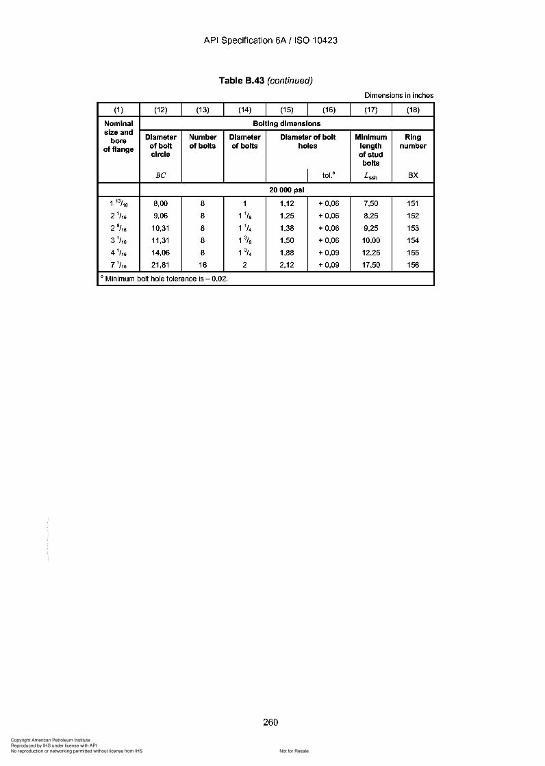
Copyright American Petroleum Institute
Reproduced by IHS under license with API
Not for ResaleNo reproduction or networking permitted without license from IHS
--`,,`,`,-`-`,,`,,`,`,,`---
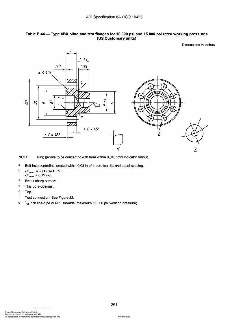
Copyright American Petroleum Institute
Reproduced by IHS under license with API
Not for ResaleNo reproduction or networking permitted without license from IHS
--`,,`,`,-`-`,,`,,`,`,,`---
API Specification 6A / ISO 10423
Table B.44 - Type 6BX blind and test flanges for 10 000 psi and 15000 psi rated working pressures(US Customary units)
Dimensions in inches
T
~ R 0,12
a"b 1,25
N
..............
y
z
zNOTE Ring groove to be concentric with bore within 0,010 total indicator runout.
a
b
c
d
e
9
Bolt hole centreline located within 0,03 in of theoretical Be and equal spacing.
Q"max. = E (Table B.52);Q"min. = 0,12 inch.
Break sharp corners.
This bore optional.
Top.
Test connection. See Figure 22.
1/2 inch line-pipe or NPT threads (maximum 10000 psi working pressure).
261
API Specification 6A / ISO 10423
Table B.44 - Type 6BX blind and test flanges for 10 000 psi and 15000 psi rated working pressures (US Customary units)
Dimensions in inches
T
a"b 1,25
~ R 0,12
N
....... .......
z
y z NOTE Ring groove to be concentric with bore within 0,010 total indicator runout.
a
b
c
d
e
9
Bolt hole centreline located within 0,03 in of theoretical Be and equal spacing.
Q" max. = E (Table B.52); Q" min. = 0,12 inch.
Break sharp corners.
This bore optional.
Top.
Test connection. See Figure 22.
1/2 inch line-pipe or NPT threads (maximum 10000 psi working pressure).
261
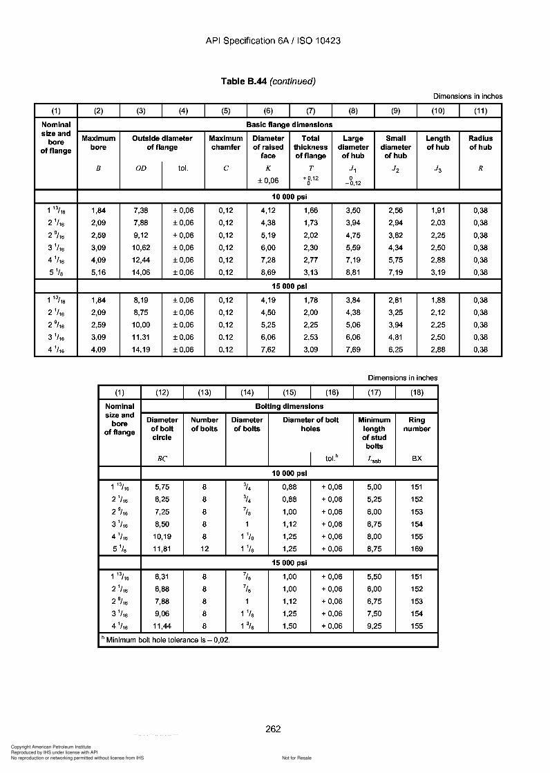
J3
Copyright American Petroleum Institute
Reproduced by IHS under license with API
Not for ResaleNo reproduction or networking permitted without license from IHS
--`,,`,`,-`-`,,`,,`,`,,`---
API Specification 6A / ISO 10423
Table B.44 (continued)
Dimensions in inches
(1 ) (2) (3) (4) (5) (6) (7) (8) (9) (10) (11 )
Nominal Basic flange dimensionssize and
Maximum Outside diameter Maximum Diameter Total Large Small Length Radiusboreof flange bore of flange chamfer of raised thickness diameter diameter of hub of hub
face of flange of hub of hub
B OD tol. C K T J 1 J2 J 3 R
±0,06 +0,12 00 -0,12
10000 psi
1 13/16 1,84 7,38 ±0,06 0,12 4,12 1,66 3,50 2,56 1,91 0,38
2 1/ 16 2,09 7,88 ±0,06 0,12 4,38 1,73 3,94 2,94 2,03 0,38
2 9/ 16 2,59 9,12 ±0,06 0,12 5,19 2,02 4,75 3,62 2,25 0,38
3 1/ 16 3,09 10,62 ±0,06 0,12 6,00 2,30 5,59 4,34 2,50 0,38
4 1/ 16 4,09 12,44 ±0,06 0,12 7,28 2,77 7,19 5,75 2,88 0,38
5 1/s 5,16 14,06 ±0,06 0,12 8,69 3,13 8,81 7,19 3,19 0,38
15000 psi
1 13/16 1,84 8,19 ±0,06 0,12 4,19 1,78 3,84 2,81 1,88 0,38
2 1/ 16 2,09 8,75 ±0,06 0,12 4,50 2,00 4,38 3,25 2,12 0,38
2 9/ 16 2,59 10,00 ±0,06 0,12 5,25 2,25 5,06 3,94 2,25 0,38
3 1/ 16 3,09 11,31 ±0,06 0,12 6,06 2,53 6,06 4,81 2,50 0,38
4 1/ 16 4,09 14,19 ±0,06 0,12 7,62 3,09 7,69 6,25 2,88 0,38
Dimensions in inches
(1 ) (12) (13) (14) (15) (16) (17) (18)
Nominal Bolting dimensionssize and
Diameter Number Diameter Diameter of bolt Minimum Ringboreof flange of bolt of bolts of bolts holes length number
circle of studbolts
BC I tol. h Lssb BX
10000 psi
1 13/16 5,75 8 % 0,88 + 0,06 5,00 151
2 1/ 16 6,25 8 % 0,88 + 0,06 5,25 152
2 9/ 16 7,25 8 7/S 1,00 + 0,06 6,00 153
3 1/ 16 8,50 8 1 1,12 + 0,06 6,75 154
4 1/ 16 10,19 8 1 1/S 1,25 + 0,06 8,00 155
5 1/s 11,81 12 1 1/S 1,25 + 0,06 8,75 169
15000 psi
1 13/16 6,31 8 7/S 1,00 + 0,06 5,50 151
2 1/ 16 6,88 8 7/S 1,00 + 0,06 6,00 152
2 9/ 16 7,88 8 1 1,12 + 0,06 6,75 153
3 1/ 16 9,06 8 1 1/S 1,25 + 0,06 7,50 154
4 1/ 16 11,44 8 1% 1,50 + 0,06 9,25 155
h Minimum bolt hole tolerance is - 0,02.
262
API Specification 6A / ISO 10423
Table B.44 (continued)
Dimensions in inches
(1 ) (2) (3) (4) (5) (6) (7) (8) (9) (10) (11 )
Nominal Basic flange dimensions size and
Maximum Outside diameter Maximum Diameter Total Large Small Length Radius bore of flange bore of flange chamfer of raised thickness diameter diameter of hub of hub
face of flange of hub of hub
B OD tol. C K T J 1 J2 J 3 R
±0,06 +0,12 0 0 -0,12
10000 psi
1 13/16 1,84 7,38 ±0,06 0,12 4,12 1,66 3,50 2,56 1,91 0,38
2 1/ 16 2,09 7,88 ±0,06 0,12 4,38 1,73 3,94 2,94 2,03 0,38
2 9/ 16 2,59 9,12 ±0,06 0,12 5,19 2,02 4,75 3,62 2,25 0,38
3 1/ 16 3,09 10,62 ±0,06 0,12 6,00 2,30 5,59 4,34 2,50 0,38
4 1/ 16 4,09 12,44 ±0,06 0,12 7,28 2,77 7,19 5,75 2,88 0,38
5 1/s 5,16 14,06 ±0,06 0,12 8,69 3,13 8,81 7,19 3,19 0,38
15000 psi
1 13/16 1,84 8,19 ±0,06 0,12 4,19 1,78 3,84 2,81 1,88 0,38
2 1/ 16 2,09 8,75 ±0,06 0,12 4,50 2,00 4,38 3,25 2,12 0,38
2 9/ 16 2,59 10,00 ±0,06 0,12 5,25 2,25 5,06 3,94 2,25 0,38
3 1/ 16 3,09 11,31 ±0,06 0,12 6,06 2,53 6,06 4,81 2,50 0,38
4 1/ 16 4,09 14,19 ±0,06 0,12 7,62 3,09 7,69 6,25 2,88 0,38
Dimensions in inches
(1 ) (12) (13) (14) (15) (16) (17) (18)
Nominal Bolting dimensions size and
Diameter Number Diameter Diameter of bolt Minimum Ring bore of flange of bolt of bolts of bolts holes length number
circle of stud bolts
BC I tol. h Lssb BX
10000 psi
1 13/16 5,75 8 % 0,88 + 0,06 5,00 151
2 1/ 16 6,25 8 % 0,88 + 0,06 5,25 152
2 9/ 16 7,25 8 7/S 1,00 + 0,06 6,00 153
3 1/ 16 8,50 8 1 1,12 + 0,06 6,75 154
4 1/ 16 10,19 8 1 1/S 1,25 + 0,06 8,00 155
5 1/s 11,81 12 1 1/S 1,25 + 0,06 8,75 169
15000 psi
1 13/16 6,31 8 7/S 1,00 + 0,06 5,50 151
2 1/ 16 6,88 8 7/S 1,00 + 0,06 6,00 152
2 9/ 16 7,88 8 1 1,12 + 0,06 6,75 153
3 1/ 16 9,06 8 1 1/S 1,25 + 0,06 7,50 154
4 1/ 16 11,44 8 1% 1,50 + 0,06 9,25 155
h Minimum bolt hole tolerance is - 0,02.
262

Copyright American Petroleum Institute
Reproduced by IHS under license with API
Not for ResaleNo reproduction or networking permitted without license from IHS
--`,,`,`,-`-`,,`,,`,`,,`---
API Specification 6A / ISO 10423
Table B.45 - Type 6BX blind and test flanges for 15 000 psi and 20 000 psi rated working pressures(US Customary units)
Dimensions in inches
T
:!: 2,50
a"b
~ R 0,12
N
.......AI
y
z
zNOTE Ring groove to be concentric with bore within 0,010 total indicator runout.
a
b
c
d
e
Bolt hole centreline located within 0,03 in of theoretical Be and equal spacing.
Q"max. = E (Table B.52);Q"min. = 0,12 inch.
Break sharp corners.
This bore optional.
Top.
Test connection. See Figure 22.
263
API Specification 6A / ISO 10423
Table B.45 - Type 6BX blind and test flanges for 15 000 psi and 20 000 psi rated working pressures (US Customary units)
Dimensions in inches
T
:!: 2,50
a"b
~ R 0,12
N
....... AI
z
y z NOTE Ring groove to be concentric with bore within 0,010 total indicator runout.
a
b
c
d
e
Bolt hole centreline located within 0,03 in of theoretical Be and equal spacing.
Q" max. = E (Table B.52); Q" min. = 0,12 inch.
Break sharp corners.
This bore optional.
Top.
Test connection. See Figure 22.
263
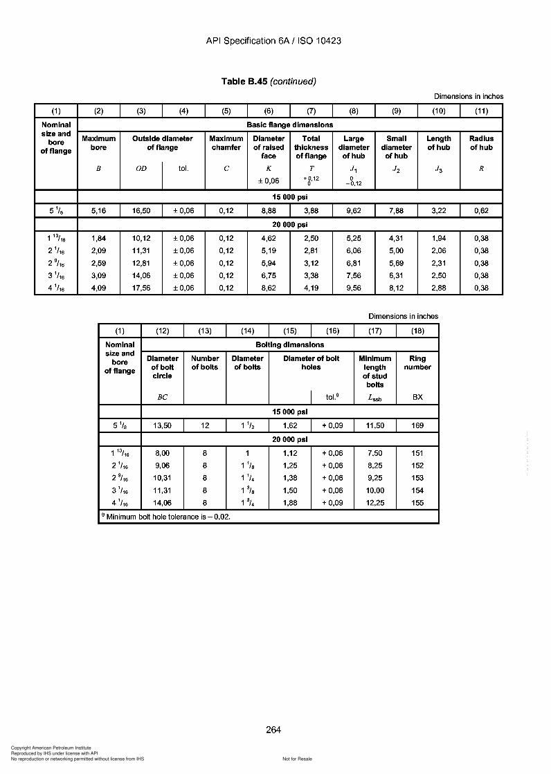
Copyright American Petroleum Institute
Reproduced by IHS under license with API
Not for ResaleNo reproduction or networking permitted without license from IHS
--`,,`,`,-`-`,,`,,`,`,,`---
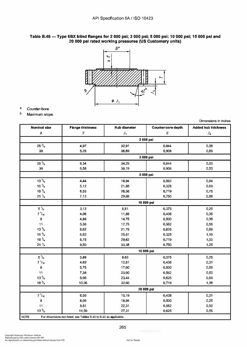
Copyright American Petroleum Institute
Reproduced by IHS under license with API
Not for ResaleNo reproduction or networking permitted without license from IHS
--`,,`,`,-`-`,,`,,`,`,,`---
API Specification 6A / ISO 10423
Table B.46 - Type 6BX blind flanges for 2000 psi; 3000 psi; 5000 psi; 10000 psi; 15000 psi and20 000 psi rated working pressures (US Customary units)
Sa
VI
....-,
a
b
Counter-bore.
Maximum slope.
Dimensions in inches
Nominal size Flange thickness Hub diameter Counter-bore depth Added hub thickness
B T J 1 E J4
2000 psi
26 3/ 4 4,97 32,91 0,844 0,38
30 5,28 36,69 0,906 0,69
3000 psi
26 3/ 4 6,34 34,25 0,844 0,00
30 6,58 38,19 0,906 0,50
5000 psi
13% 4,44 18,94 0,562 0,94
16 3/ 4 5,12 21,88 0,328 0,69
18 3/ 4 6,53 26,56 0,719 0,75
21 1/4 7,12 29,88 0,750 0,88
10000 psi
5 1/s 3,12 8,81 0,375 0,25
7 1/ 16 4,06 11,88 0,438 0,38
9 4,88 14,75 0,500 0,38
11 5,56 17,75 0,562 0,56
13% 6,62 21,75 0,625 0,69
16% 6,62 25,81 0,328 1,19
18% 8,78 29,62 0,719 1,0021 1/4 9,50 33,38 0,750 1,25
15000 psi
5 1/s 3,88 9,62 0,375 0,257 1
/ 16 4,69 12,81 0,438 0,31
9 5,75 17,00 0,500 0,56
11 7,38 23,00 0,562 0,50
13% 8,06 23,44 0,625 0,69
18% 10,06 32,00 0,719 1,38
20000 psi
7 1/ 16 6,50 15,19 0,438 0,31
9 8,06 18,94 0,500 0,25
11 8,81 22,31 0,562 0,50
13% 11,50 27,31 0,625 0,56
NOTE For dimensions not listed. see Tables B.40 to B.45 as applicable.
265
a
b
API Specification 6A / ISO 10423
Table B.46 - Type 6BX blind flanges for 2000 psi; 3000 psi; 5000 psi; 10000 psi; 15000 psi and 20 000 psi rated working pressures (US Customary units)
Counter-bore.
Maximum slope.
Nominal size
B
26 3/ 4
30
26 3/ 4
30
13% 16 3
/ 4
18 3/ 4
21 1/4
5 1/8
7 1/ 16
9 11
13%
16%
18% 21 1/4
5 1/8
7 1/ 16
9
11
13% 18%
7 1/ 16
9 11
13%
Sa
VI
Flange thickness Hub diameter
T J 1
4,97 32,91 5,28 36,69
6,34 34,25 6,58 38,19
4,44 18,94
5,12 21,88
6,53 26,56 7,12 29,88
3,12 8,81
4,06 11,88
4,88 14,75
5,56 17,75
6,62 21,75
6,62 25,81
8,78 29,62
9,50 33,38
3,88 9,62 4,69 12,81
5,75 17,00
7,38 23,00
8,06 23,44 10,06 32,00
6,50 15,19
8,06 18,94
8,81 22,31 11,50 27,31
NOTE For dimensions not listed, see Tables B.40 to B.45 as applicable.
265
Dimensions in inches
Counter-bore depth Added hub thickness
E J4
2000 psi
0,844 0,38 0,906 0,69
3000 psi
0,844 0,00 0,906 0,50
5000 psi
0,562 0,94
0,328 0,69
0,719 0,75 0,750 0,88
10000 psi
0,375 0,25
0,438 0,38
0,500 0,38
0,562 0,56
0,625 0,69
0,328 1,19
0,719 1,00
0,750 1,25
15000 psi
0,375 0,25 0,438 0,31
0,500 0,56
0,562 0,50
0,625 0,69 0,719 1,38
20000 psi
0,438 0,31
0,500 0,25
0,562 0,50 0,625 0,56
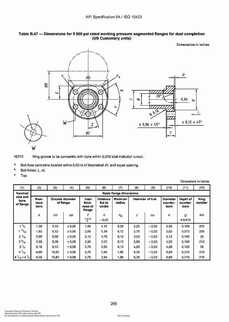
Copyright American Petroleum Institute
Reproduced by IHS under license with API
Not for ResaleNo reproduction or networking permitted without license from IHS
--`,,`,`,-`-`,,`,,`,`,,`---
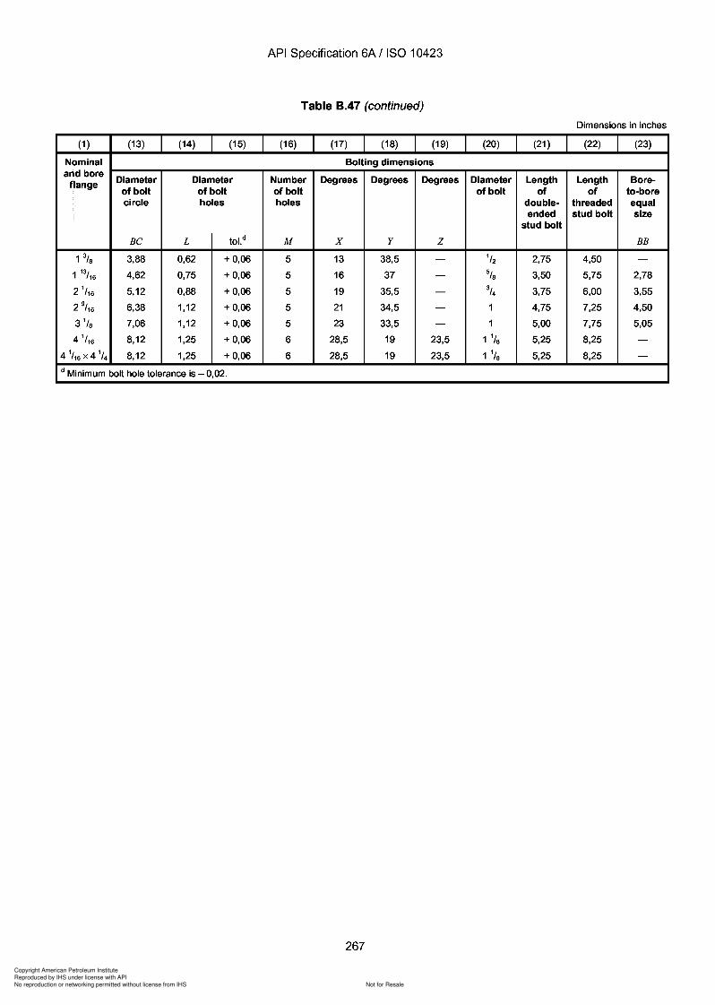
Copyright American Petroleum Institute
Reproduced by IHS under license with API
Not for ResaleNo reproduction or networking permitted without license from IHS
--`,,`,`,-`-`,,`,,`,`,,`---
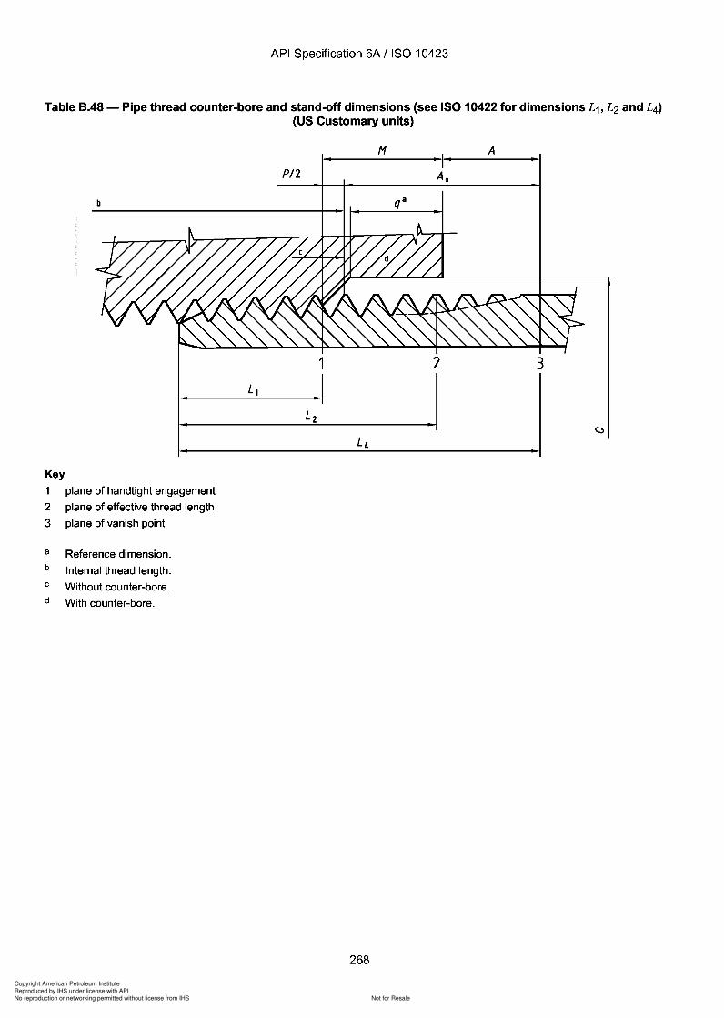
Copyright American Petroleum Institute
Reproduced by IHS under license with API
Not for ResaleNo reproduction or networking permitted without license from IHS
--`,,`,`,-`-`,,`,,`,`,,`---
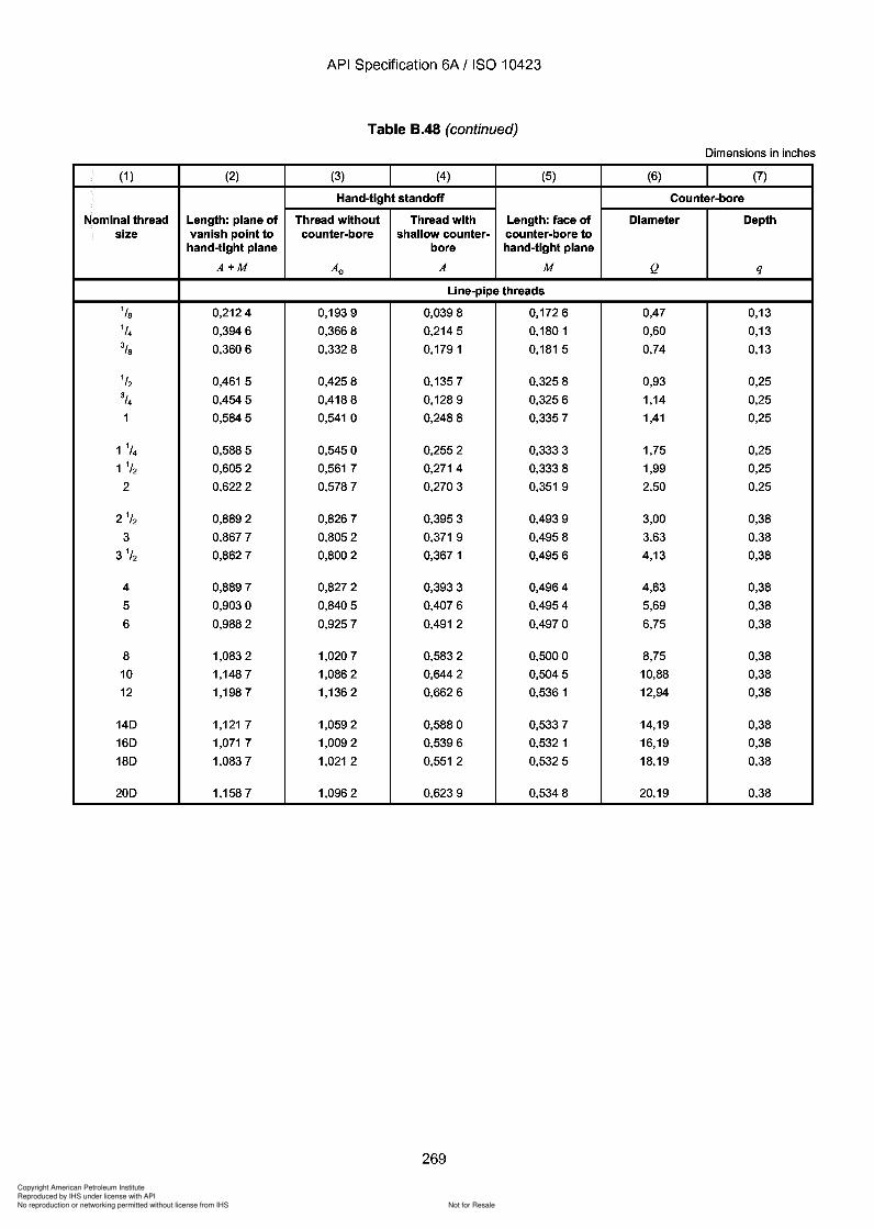
Copyright American Petroleum Institute
Reproduced by IHS under license with API
Not for ResaleNo reproduction or networking permitted without license from IHS
--`,,`,`,-`-`,,`,,`,`,,`---
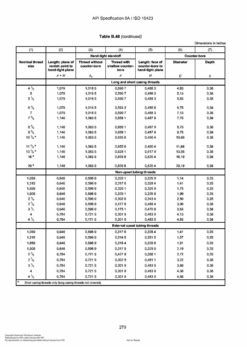
Copyright American Petroleum Institute
Reproduced by IHS under license with API
Not for ResaleNo reproduction or networking permitted without license from IHS
--`,,`,`,-`-`,,`,,`,`,,`---
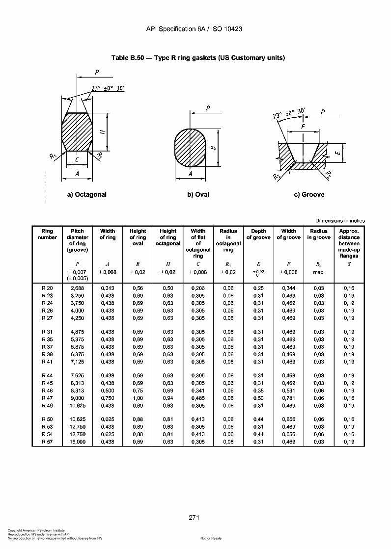
Copyright American Petroleum Institute
Reproduced by IHS under license with API
Not for ResaleNo reproduction or networking permitted without license from IHS
--`,,`,`,-`-`,,`,,`,`,,`---
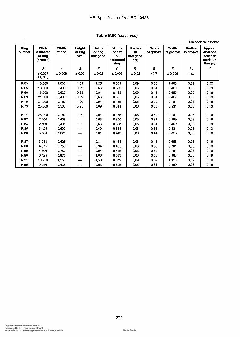
Copyright American Petroleum Institute
Reproduced by IHS under license with API
Not for ResaleNo reproduction or networking permitted without license from IHS
--`,,`,`,-`-`,,`,,`,`,,`---

Copyright American Petroleum Institute
Reproduced by IHS under license with API
Not for ResaleNo reproduction or networking permitted without license from IHS
--`,,`,`,-`-`,,`,,`,`,,`---
API Specification 6A / ISO 10423
Table 8.51 - Type RX pressure-energized ring gaskets (US Customary units)
A
OD
a The pressure passage hole illustrated in the RX ring cross-section applies to rings RX-82 through RX-91 only. Centreline ofhole shall be located at midpoint of dimension C. Hole diameter shall be 0,06 in for rings RX-82 through RX-85, 0,09 in for ringsRX-86 and RX-87, and 0,12 in for rings RX-88 through RX-91.
Dimensions in inches
Ring Pitch Outside Width Width Height Height Radius Depth Width Radius Approx.number diameter diameter of ring of flat of of ring in ring of of in distance
of ring of ring outside groove groove groove betweenand bevel made-up
groove flangesp OD Ad C D Hd R1 E F R2 S
±0,005 + 0,020 + 0,008 + 0,006 0 + 0,008 ±0,02 + 0,02 ±0,008 max.0 0 0 - 0,Q3 0 0
RX20 2,688 3,000 0,344 0,182 0,125 0,750 0,06 0,25 0,344 0,03 0,38RX23 3,250 3,672 0,469 0,254 0,167 1,000 0,06 0,31 0,469 0,03 0,47
RX24 3,750 4,172 0,469 0,254 0,167 1,000 0,06 0,31 0,469 0,03 0,47
RX25 4,000 4,313 0,344 0,182 0,125 0,750 0,06 0,25 0,344 0,03 -RX26 4,000 4,406 0,469 0,254 0,167 1,000 0,06 0,31 0,469 0,03 0,47
RX27 4,250 4,656 0,469 0,254 0,167 1,000 0,06 0,31 0,469 0,03 0,47
RX31 4,875 5,297 0,469 0,254 0,167 1,000 0,06 0,31 0,469 0,03 0,47
RX35 5,375 5,797 0,469 0,254 0,167 1,000 0,06 0,31 0,469 0,03 0,47
RX37 5,875 6,297 0,469 0,254 0,167 1,000 0,06 0,31 0,469 0,03 0,47
RX39 6,375 6,797 0,469 0,254 0,167 1,000 0,06 0,31 0,469 0,03 0,47
RX41 7,125 7,547 0,469 0,254 0,167 1,000 0,06 0,31 0,469 0,03 0,47
RX44 7,625 8,047 0,469 0,254 0,167 1,000 0,06 0,31 0,469 0,03 0,47
RX45 8,313 8,734 0,469 0,254 0,167 1,000 0,06 0,31 0,469 0,03 0,47
RX46 8,313 8,750 0,531 0,263 0,188 1,125 0,06 0,38 0,531 0,06 0,47
RX47 9,000 9,656 0,781 0,407 0,271 1,625 0,09 0,50 0,781 0,06 0,91
RX49 10,625 11,047 0,469 0,254 0,167 1,000 0,06 0,31 0,469 0,03 0,47
RX50 10,625 11,156 0,656 0,335 0,208 1,250 0,06 0,44 0,656 0,06 0,47
RX53 12,750 13,172 0,469 0,254 0,167 1,000 0,06 0,31 0,469 0,03 0,47
RX54 12,750 13,281 0,656 0,335 0,208 1,250 0,06 0,44 0,656 0,06 0,47RX57 15,000 15,422 0,469 0,254 0,167 1,000 0,06 0,31 0,469 0,03 0,47
273
API Specification 6A / ISO 10423
Table 8.51 - Type RX pressure-energized ring gaskets (US Customary units)
A
00
a The pressure passage hole illustrated in the RX ring cross-section applies to rings RX-82 through RX-91 only. Centreline of hole shall be located at midpoint of dimension C. Hole diameter shall be 0,06 in for rings RX-82 through RX-85 , 0,09 in for rings RX-86 and RX-87, and 0,12 in for rings RX-88 through RX-91.
Dimensions in inches
Ring Pitch Outside Width Width Height Height Radius Depth Width Radius Approx. number diameter diameter of ring of flat of of ring in ring of of in distance
of ring of ring outside groove groove groove between and bevel made-up
groove flanges p OD Ad C D Hd R1 E F R2 S
±0,005 + 0,020 + 0,008 + 0,006 0 + 0,008 ±0,02 + 0,02 ±0,008 max. 0 0 0 - 0,Q3 0 0
RX20 2,688 3,000 0,344 0,182 0,125 0,750 0,06 0,25 0,344 0,03 0,38 RX23 3,250 3,672 0,469 0,254 0,167 1,000 0,06 0,31 0,469 0,03 0,47
RX24 3,750 4,172 0,469 0,254 0,167 1,000 0,06 0,31 0,469 0,03 0,47
RX25 4,000 4,313 0,344 0,182 0,125 0,750 0,06 0,25 0,344 0,03 -RX26 4,000 4,406 0,469 0,254 0,167 1,000 0,06 0,31 0,469 0,03 0,47
RX27 4,250 4,656 0,469 0,254 0,167 1,000 0,06 0,31 0,469 0,03 0,47
RX31 4,875 5,297 0,469 0,254 0,167 1,000 0,06 0,31 0,469 0,03 0,47
RX35 5,375 5,797 0,469 0,254 0,167 1,000 0,06 0,31 0,469 0,03 0,47
RX37 5,875 6,297 0,469 0,254 0,167 1,000 0,06 0,31 0,469 0,03 0,47
RX39 6,375 6,797 0,469 0,254 0,167 1,000 0,06 0,31 0,469 0,03 0,47
RX41 7,125 7,547 0,469 0,254 0,167 1,000 0,06 0,31 0,469 0,03 0,47
RX44 7,625 8,047 0,469 0,254 0,167 1,000 0,06 0,31 0,469 0,03 0,47
RX45 8,313 8,734 0,469 0,254 0,167 1,000 0,06 0,31 0,469 0,03 0,47
RX46 8,313 8,750 0,531 0,263 0,188 1,125 0,06 0,38 0,531 0,06 0,47
RX47 9,000 9,656 0,781 0,407 0,271 1,625 0,09 0,50 0,781 0,06 0,91
RX49 10,625 11,047 0,469 0,254 0,167 1,000 0,06 0,31 0,469 0,03 0,47
RX50 10,625 11,156 0,656 0,335 0,208 1,250 0,06 0,44 0,656 0,06 0,47
RX53 12,750 13,172 0,469 0,254 0,167 1,000 0,06 0,31 0,469 0,03 0,47
RX54 12,750 13,281 0,656 0,335 0,208 1,250 0,06 0,44 0,656 0,06 0,47 RX57 15,000 15,422 0,469 0,254 0,167 1,000 0,06 0,31 0,469 0,03 0,47
273
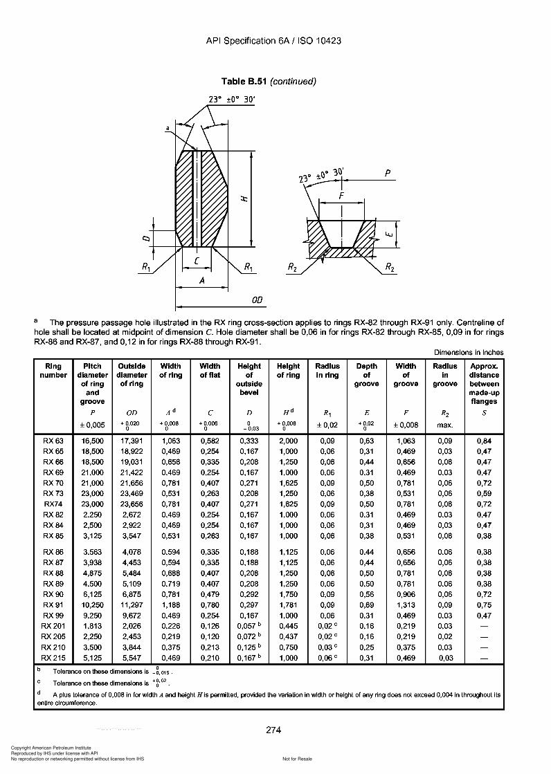
Copyright American Petroleum Institute
Reproduced by IHS under license with API
Not for ResaleNo reproduction or networking permitted without license from IHS
--`,,`,`,-`-`,,`,,`,`,,`---
API Specification 6A / ISO 10423
Table 8.51 (continued)
A
OD
a The pressure passage hole illustrated in the RX ring cross-section applies to rings RX-82 through RX-91 only. Centreline ofhole shall be located at midpoint of dimension C. Hole diameter shall be 0,06 in for rings RX-82 through RX-85, 0,09 in for ringsRX-86 and RX-87, and 0,12 in for rings RX-88 through RX-91.
Dimensions in inches
Ring Pitch Outside Width Width Height Height Radius Depth Width Radius Approx.number diameter diameter of ring of flat of of ring in ring of of in distance
of ring of ring outside groove groove groove betweenand bevel made-up
groove flangesp OD Ad C D H d R1 E F R2 S
±0,005 + 0,020 + 0,008 + 0,006 0 + 0,008 ±0,02 +0,02 ±0,008 max.0 0 0 - 0,Q3 0 0
RX63 16,500 17,391 1,063 0,582 0,333 2,000 0,09 0,63 1,063 0,09 0,84RX65 18,500 18,922 0,469 0,254 0,167 1,000 0,06 0,31 0,469 0,03 0,47
RX66 18,500 19,031 0,656 0,335 0,208 1,250 0,06 0,44 0,656 0,06 0,47
RX69 21,000 21,422 0,469 0,254 0,167 1,000 0,06 0,31 0,469 0,03 0,47
RX70 21,000 21,656 0,781 0,407 0,271 1,625 0,09 0,50 0,781 0,06 0,72RX73 23,000 23,469 0,531 0,263 0,208 1,250 0,06 0,38 0,531 0,06 0,59RX74 23,000 23,656 0,781 0,407 0,271 1,625 0,09 0,50 0,781 0,06 0,72
RX82 2,250 2,672 0,469 0,254 0,167 1,000 0,06 0,31 0,469 0,03 0,47
RX84 2,500 2,922 0,469 0,254 0,167 1,000 0,06 0,31 0,469 0,03 0,47
RX85 3,125 3,547 0,531 0,263 0,167 1,000 0,06 0,38 0,531 0,06 0,38
RX86 3,563 4,078 0,594 0,335 0,188 1,125 0,06 0,44 0,656 0,06 0,38RX87 3,938 4,453 0,594 0,335 0,188 1,125 0,06 0,44 0,656 0,06 0,38RX88 4,875 5,484 0,688 0,407 0,208 1,250 0,06 0,50 0,781 0,06 0,38RX89 4,500 5,109 0,719 0,407 0,208 1,250 0,06 0,50 0,781 0,06 0,38RX90 6,125 6,875 0,781 0,479 0,292 1,750 0,09 0,56 0,906 0,06 0,72
RX91 10,250 11,297 1,188 0,780 0,297 1,781 0,09 0,69 1,313 0,09 0,75
RX99 9,250 9,672 0,469 0,254 0,167 1,000 0,06 0,31 0,469 0,03 0,47RX201 1,813 2,026 0,226 0,126 0,057 b 0,445 0,02 e 0,16 0,219 0,03 -RX205 2,250 2,453 0,219 0,120 0,072 b 0,437 0,02 e 0,16 0,219 0,02 -RX210 3,500 3,844 0,375 0,213 0,125 b 0,750 0,03 e 0,25 0,375 0,03 -RX215 5,125 5,547 0,469 0,210 0,167 b 1,000 0,06 e 0,31 0,469 0,03 -
b Tolerance on these dimensions is -K 015 .
e Tolerance on these dimensions is +g,02 .
d A plus tolerance of 0,008 in for width A and height H is permitted, provided the variation in width or height of any ring does not exceed 0,004 in throughout itsentire circumference.
274
API Specification 6A / ISO 10423
Table 8.51 (continued)
A
OD
a The pressure passage hole illustrated in the RX ring cross-section applies to rings RX-82 through RX-91 only. Centreline of hole shall be located at midpoint of dimension C. Hole diameter shall be 0,06 in for rings RX-82 through RX-85 , 0,09 in for rings RX-86 and RX-87, and 0,12 in for rings RX-88 through RX-91.
Dimensions in inches
Ring Pitch Outside Width Width Height Height Radius Depth Width Radius Approx. number diameter diameter of ring of flat of of ring in ring of of in distance
of ring of ring outside groove groove groove between and bevel made-up
groove flanges p OD Ad C D Hd R1 E F R2 S
±0,005 + 0,020 + 0,008 + 0,006 0 + 0,008 ±0,02 +0,02 ±0,008 max. 0 0 0 - 0,Q3 0 0
RX63 16,500 17,391 1,063 0,582 0,333 2,000 0,09 0,63 1,063 0,09 0,84 RX65 18,500 18,922 0,469 0,254 0,167 1,000 0,06 0,31 0,469 0,03 0,47
RX66 18,500 19,031 0,656 0,335 0,208 1,250 0,06 0,44 0,656 0,06 0,47
RX69 21,000 21,422 0,469 0,254 0,167 1,000 0,06 0,31 0,469 0,03 0,47
RX70 21,000 21,656 0,781 0,407 0,271 1,625 0,09 0,50 0,781 0,06 0,72 RX73 23,000 23,469 0,531 0,263 0,208 1,250 0,06 0,38 0,531 0,06 0,59 RX74 23,000 23,656 0,781 0,407 0,271 1,625 0,09 0,50 0,781 0,06 0,72
RX82 2,250 2,672 0,469 0,254 0,167 1,000 0,06 0,31 0,469 0,03 0,47
RX84 2,500 2,922 0,469 0,254 0,167 1,000 0,06 0,31 0,469 0,03 0,47
RX85 3,125 3,547 0,531 0,263 0,167 1,000 0,06 0,38 0,531 0,06 0,38
RX86 3,563 4,078 0,594 0,335 0,188 1,125 0,06 0,44 0,656 0,06 0,38 RX87 3,938 4,453 0,594 0,335 0,188 1,125 0,06 0,44 0,656 0,06 0,38 RX88 4,875 5,484 0,688 0,407 0,208 1,250 0,06 0,50 0,781 0,06 0,38 RX89 4,500 5,109 0,719 0,407 0,208 1,250 0,06 0,50 0,781 0,06 0,38 RX90 6,125 6,875 0,781 0,479 0,292 1,750 0,09 0,56 0,906 0,06 0,72
RX91 10,250 11,297 1,188 0,780 0,297 1,781 0,09 0,69 1,313 0,09 0,75
RX99 9,250 9,672 0,469 0,254 0,167 1,000 0,06 0,31 0,469 0,03 0,47 RX201 1,813 2,026 0,226 0,126 0,057 b 0,445 0,02 e 0,16 0,219 0,03 -RX205 2,250 2,453 0,219 0,120 0,072 b 0,437 0,02 e 0,16 0,219 0,02 -RX210 3,500 3,844 0,375 0,213 0,125 b 0,750 0,03 e 0,25 0,375 0,03 -RX215 5,125 5,547 0,469 0,210 0,167 b 1,000 0,06 e 0,31 0,469 0,03 -
b Tolerance on these dimensions is -K 015 .
e Tolerance on these dimensions is +g,02 .
d A plus tolerance of 0,008 in for width A and height H is permitted, provided the variation in width or height of any ring does not exceed 0,004 in throughout its entire circumference.
274

Copyright American Petroleum Institute
Reproduced by IHS under license with API
Not for ResaleNo reproduction or networking permitted without license from IHS
--`,,`,`,-`-`,,`,,`,`,,`---
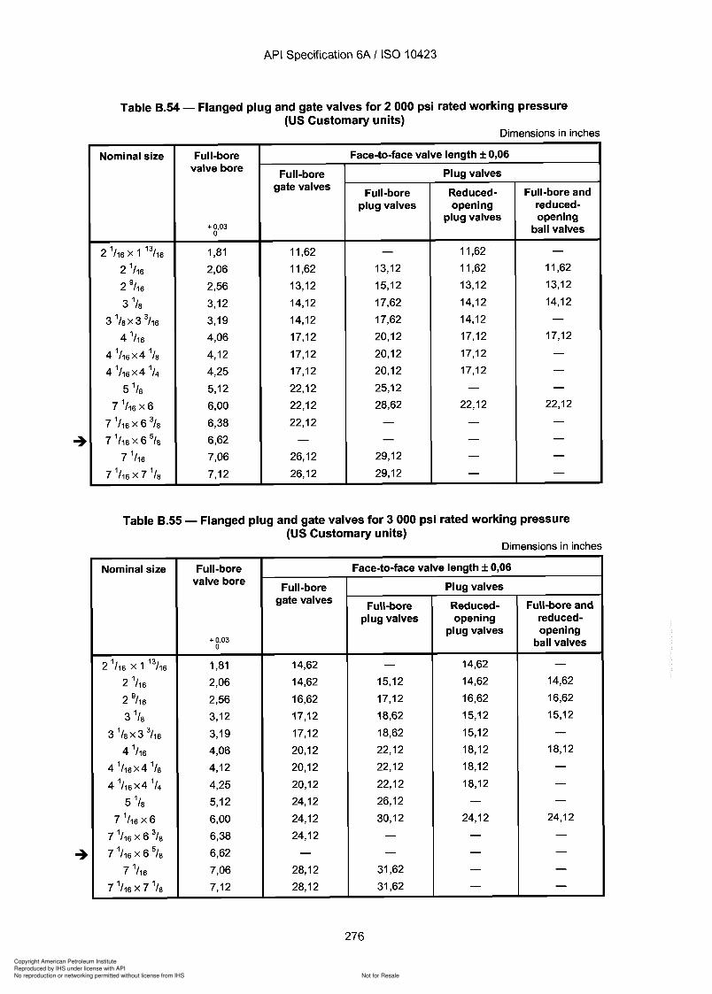
Copyright American Petroleum Institute
Reproduced by IHS under license with API
Not for ResaleNo reproduction or networking permitted without license from IHS
--`,,`,`,-`-`,,`,,`,`,,`---
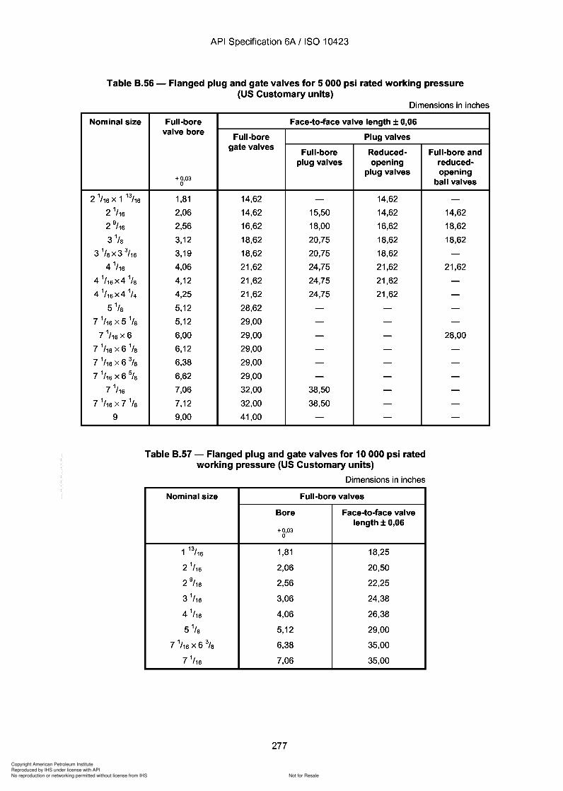
Copyright American Petroleum Institute
Reproduced by IHS under license with API
Not for ResaleNo reproduction or networking permitted without license from IHS
--`,,`,`,-`-`,,`,,`,`,,`---
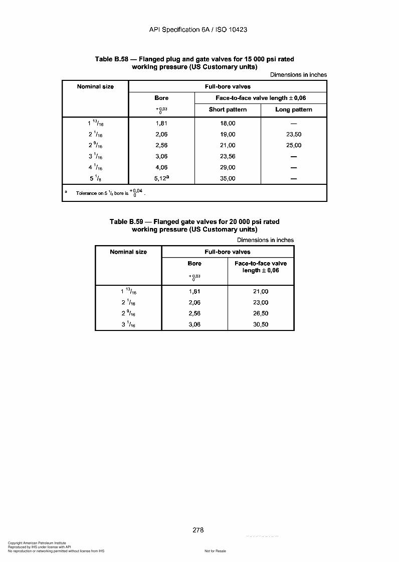
Copyright American Petroleum Institute
Reproduced by IHS under license with API
Not for ResaleNo reproduction or networking permitted without license from IHS
--`,,`,`,-`-`,,`,,`,`,,`---
API Specification 6A / ISO 10423
Table B.58 - Flanged plug and gate valves for 15 000 psi ratedworking pressure (US Customary units)
Dimensions in inches
Nominal size Full-bore valves
Bore Face-to-face valve length ± 0,06
+0,03 Short pattern Long pattern0
1 13/16 1,81 18,00 -2
1/16 2,06 19,00 23,50
2 9/ 16 2,56 21,00 25,00
31/16 3,06 23,56 -
41/16 4,06 29,00 -
5 1/ 8 5,128 35,00 -
a Tolerance on 5 '/a bore is + g,04
Table B.59 - Flanged gate valves for 20 000 psi ratedworking pressure (US Customary units)
Dimensions in inches
Nominal size Full-bore valves
Bore Face-to-face valvelength ± 0,06
+ 0,030
1 13/16 1,81 21,00
21/16 2,06 23,00
2 9/ 16 2,56 26,50
31/16 3,06 30,50
278
a
API Specification 6A / ISO 10423
Table B.58 - Flanged plug and gate valves for 15 000 psi rated working pressure (US Customary units)
Dimensions in inches
Nominal size Full-bore valves
Bore Face-to-face valve length ± 0,06
+0,03 Short pattern Long pattern 0
1 13/16 1,81 18,00 -2
1/16 2,06 19,00 23,50
2 9/ 16 2,56 21,00 25,00
3 1/16 3,06 23,56 -
41/16 4,06 29,00 -
51/8 5,12a 35,00 -
Tolerance on 5 '/a bore is + g,04
Table B.59 - Flanged gate valves for 20 000 psi rated working pressure (US Customary units)
Dimensions in inches
Nominal size Full-bore valves
Bore Face-to-face valve length ± 0,06
+ 0,03 0
1 13/16 1,81 21,00
21/16 2,06 23,00
2 9/ 16 2,56 26,50
31/16 3,06 30,50
278
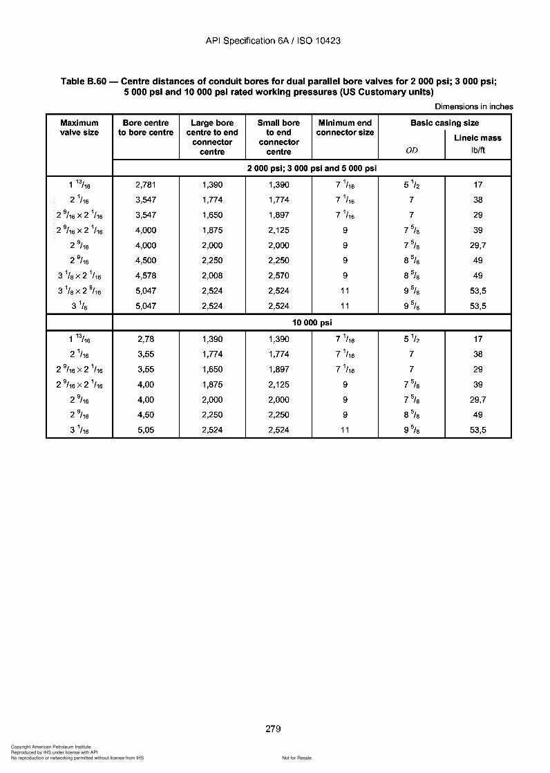
Copyright American Petroleum Institute
Reproduced by IHS under license with API
Not for ResaleNo reproduction or networking permitted without license from IHS
--`,,`,`,-`-`,,`,,`,`,,`---
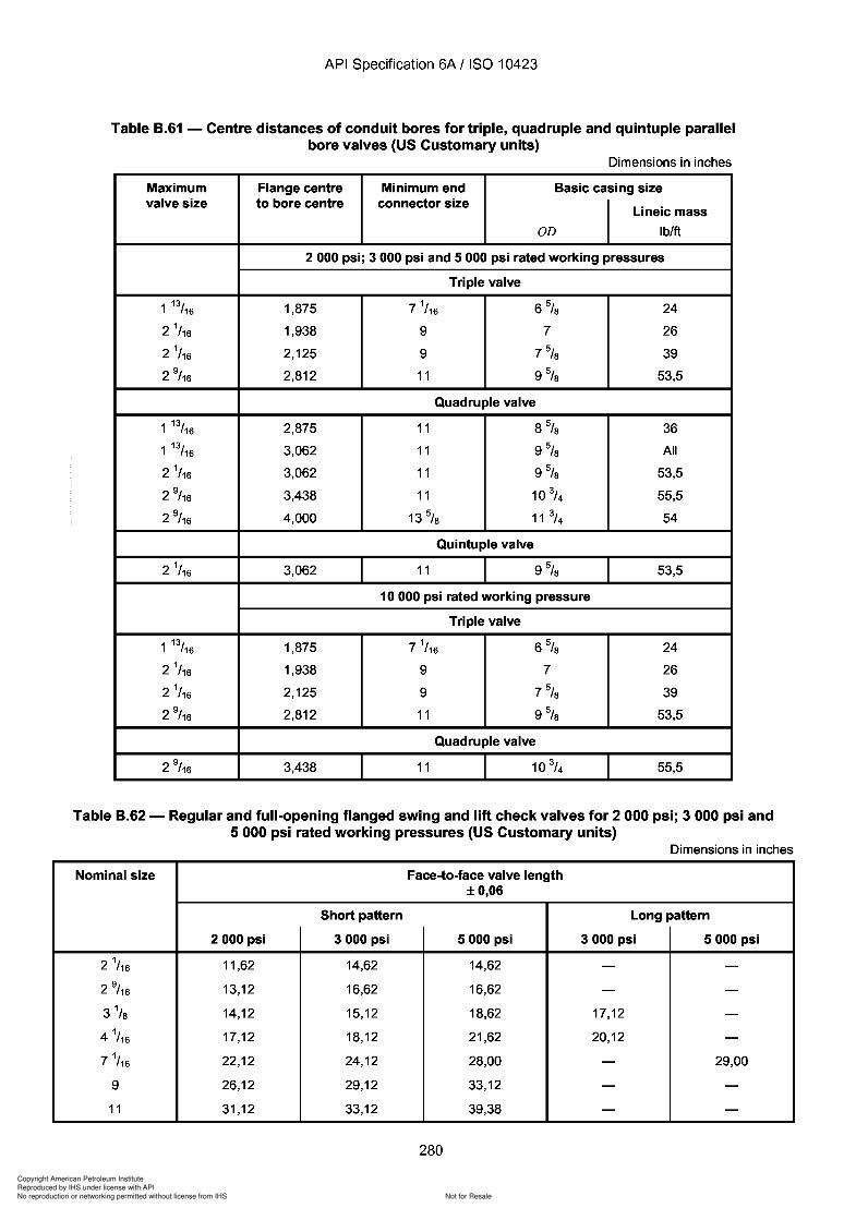
Copyright American Petroleum Institute
Reproduced by IHS under license with API
Not for ResaleNo reproduction or networking permitted without license from IHS
--`,,`,`,-`-`,,`,,`,`,,`---
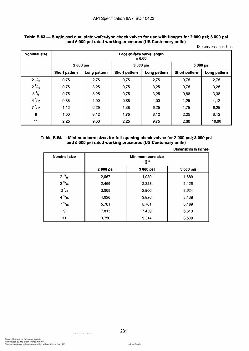
Copyright American Petroleum Institute
Reproduced by IHS under license with API
Not for ResaleNo reproduction or networking permitted without license from IHS
--`,,`,`,-`-`,,`,,`,`,,`---
API Specification 6A / ISO 10423
Table 8.63 - Single and dual plate wafer-type check valves for use with flanges for 2 000 psi; 3 000 psiand 5000 psi rated working pressures (US Customary units)
Dimensions in inches
Nominal size Face-to-face valve length±0,06
2000 psi 3000 psi 5000 psi
Short pattern Long pattern Short pattern Long pattern Short pattern Long pattern
21/16 0,75 2,75 0,75 2,75 0,75 2,75
2 9/ 16 0,75 3,25 0,75 3,25 0,75 3,25
3 1/8 0,75 3,25 0,75 3,25 0,88 3,38
4 1/16 0,88 4,00 0,88 4,00 1,25 4,12
71/16 1,12 6,25 1,38 6,25 1,75 6,25
9 1,50 8,12 1,75 8,12 2,25 8,12
11 2,25 9,50 2,25 9,75 2,88 10,00
Table 8.64 - Minimum bore sizes for full-opening check valves for 2000 psi; 3000 psiand 5000 psi rated working pressures (US Customary units)
Dimensions in inches
Nominal size Minimum bore size+0,06
0
2000 psi 3000 psi 5000 psi
21/16 2,067 1,939 1,689
2 9/ 16 2,469 2,323 2,125
3 1/8 3,068 2,900 2,624
4 1/16 4,026 3,826 3,438
71/16 5,761 5,761 5,189
9 7,813 7,439 6,813
11 9,750 9,314 8,500
281
API Specification 6A / ISO 10423
Table 8.63 - Single and dual plate wafer-type check valves for use with flanges for 2 000 psi; 3 000 psi and 5000 psi rated working pressures (US Customary units)
Dimensions in inches
Nominal size Face-to-face valve length
21/16
2 9/ 16
31/8
4 1/16
71/16
9
11
±0,06
2000 psi 3000 psi 5000 psi
Short pattern Long pattern Short pattern Long pattern Short pattern Long pattern
0,75 2,75 0,75 2,75 0,75
0,75 3,25 0,75 3,25 0,75
0,75 3,25 0,75 3,25 0,88
0,88 4,00 0,88 4,00 1,25
1,12 6,25 1,38 6,25 1,75
1,50 8,12 1,75 8,12 2,25
2,25 9,50 2,25 9,75 2,88
Table 8.64 - Minimum bore sizes for full-opening check valves for 2000 psi; 3000 psi and 5000 psi rated working pressures (US Customary units)
Dimensions in inches
Nominal size Minimum bore size +0,06
0
2000 psi 3000 psi 5000 psi
21/16 2,067 1,939 1,689
2 9/ 16 2,469 2,323 2,125
31/8 3,068 2,900 2,624
4 1/16 4,026 3,826 3,438
71/16 5,761 5,761 5,189
9 7,813 7,439 6,813
11 9,750 9,314 8,500
281
2,75
3,25
3,38
4,12
6,25
8,12
10,00
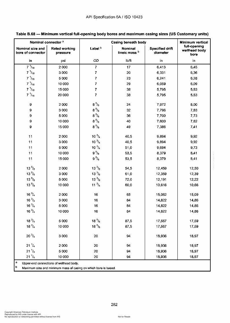
Copyright American Petroleum Institute
Reproduced by IHS under license with API
Not for ResaleNo reproduction or networking permitted without license from IHS
--`,,`,`,-`-`,,`,,`,`,,`---
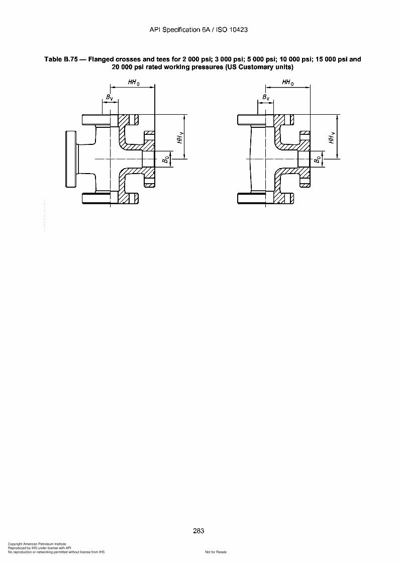
Copyright American Petroleum Institute
Reproduced by IHS under license with API
Not for ResaleNo reproduction or networking permitted without license from IHS
--`,,`,`,-`-`,,`,,`,`,,`---
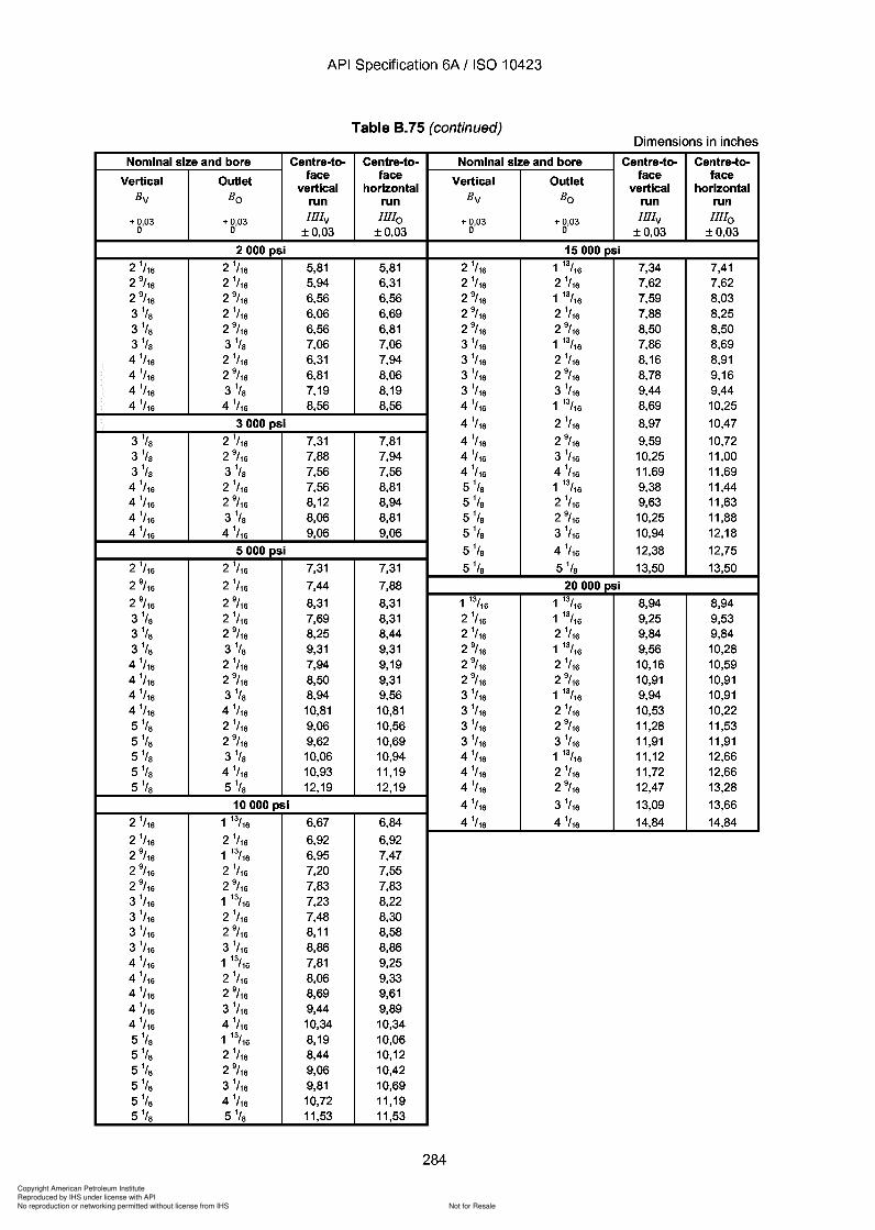
Copyright American Petroleum Institute
Reproduced by IHS under license with API
Not for ResaleNo reproduction or networking permitted without license from IHS
--`,,`,`,-`-`,,`,,`,`,,`---
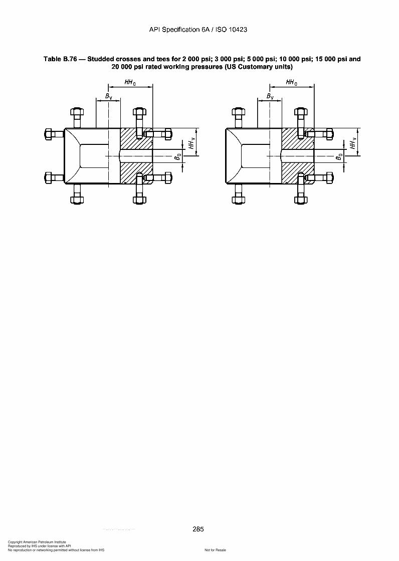
Copyright American Petroleum Institute
Reproduced by IHS under license with API
Not for ResaleNo reproduction or networking permitted without license from IHS
--`,,`,`,-`-`,,`,,`,`,,`---
API Specification 6A / ISO 10423
Table 8.76 - Studded crosses and tees for 2000 psi; 3000 psi; 5000 psi; 10000 psi; 15000 psi and20 000 psi rated working pressures (US Customary units)
HH o
>
~~...L.L.L.L."-t-----+
285
HH o
API Specification 6A / ISO 10423
Table 8.76 - Studded crosses and tees for 2000 psi; 3000 psi; 5000 psi; 10000 psi; 15000 psi and 20 000 psi rated working pressures (US Customary units)
HHo HHo
>
~...L.L.L.L.."-t-----+ ~
285

Copyright American Petroleum Institute
Reproduced by IHS under license with API
Not for ResaleNo reproduction or networking permitted without license from IHS
--`,,`,`,-`-`,,`,,`,`,,`---
API Specification 6A / ISO 10423
Table 8.76 (continued)Dimensions in inches
Nominal size and bore Centre-to- Centre-to- Nominal size and bore Centre-to- Centre-to-
Vertical Outlet face face Vertical Outlet face facevertical horizontal vertical horizontal
Bv Bo run run Bv Bo run run
+0,03 +0,03 HHv HHo + 0,03 + 0,03 HHv HHo0 0 ±0,03 ±0,03 0 0 ±0,03 ±0,03
2000 psi 15000 psi
2 1/ 16 2 1
/ 16 3,50 3,50 1 13/16 1 13/16 5,00 5,002 9
/ 16 2 1/ 16 3,50 4,00 2 1
/ 16 1 13/16 5,00 5,002 9
/ 16 2 9/ 16 4,50 4,50 2 1
/ 16 2 1/ 16 5,00 5,00
3 1/ S 2 1
/ 16 3,50 4,50 2 9/ 16 1 13/16 5,50 5,50
3 1/s 2 9/ 16 4,50 4,50 2 9
/ 16 2 1/ 16 5,50 5,50
3 1/ S 3 1/s 4,50 4,50 2 9
/ 16 2 9/ 16 5,50 5,50
4 1/ 16 2 1
/ 16 4,50 5,50 3 1/ 16 1 13/16 6,31 6,31
4 1/ 16 2 9
/ 16 4,50 5,50 3 1/ 16 2 1
/ 16 6,31 6,314 1
/ 16 3 1/ S 4,50 5,50 3 1
/ 16 2 9/ 16 6,31 6,31
4 1/ 16 4 1
/ 16 5,50 5,50 3 1/ 16 3 1
/ 16 6,31 6,31
3000 psi 4 1/ 16 1 13/16 7,62 7,62
3 1/s 2 1/ 16 4,50 5,00 4 1
/ 16 2 1/ 16 7,62 7,62
3 1/ S 2 9
/ 16 5,00 5,00 4 1/ 16 2 9
/ 16 7,62 7,623 1/s 3 1
/ S 5,00 5,00 4 1/ 16 3 1
/ 16 7,62 7,624 1
/ 16 2 1/ 16 4,50 6,12 4 1
/ 16 4 1/ 16 7,62 7,62
4 1/ 16 2 9
/ 16 5,00 6,12 5 1/s 1 13/16 6,62 8,754 1
/ 16 3 1/ S 5,00 6,12 5 1/s 2 1
/ 16 6,62 8,754 1
/ 16 4 1/ 16 6,12 6,12 5 1/s 2 9
/ 16 6,62 8,75
5000 psi 5 1/s 3 1/ 16 6,62 8,75
2 1/ 16 2 1
/ 16 4,50 4,50 5 1/s 4 1/ 16 9,25 9,25
2 9/ 16 2 1
/ 16 4,50 5,00 5 1/s 5 1/s 9,25 9,25
2 9/ 16 2 9
/ 16 5,00 5,00 20000 psi
3 1/ S 2 1
/ 16 4,50 5,50 1 13/16 1 13/16 6,47 6,473 1
/ S 2 9/ 16 5,50 5,50 2 1
/ 16 1 13/16 6,47 6,473 1
/ S 3 1/ S 5,50 5,50 2 1
/ 16 2 1/ 16 6,47 6,47
4 1/ 16 2 1
/ 16 4,50 6,50 2 9/ 16 1 13/16 7,28 7,28
4 1/ 16 2 9
/ 16 5,00 6,50 2 9/ 16 2 1
/ 16 7,28 7,284 1
/ 16 3 1/ S 5,50 6,50 2 9
/ 16 2 9/ 16 7,28 7,28
4 1/ 16 4 1
/ 16 6,50 6,50 3 1/ 16 1 13/16 7,97 7,97
5 1/s 2 1/ 16 6,12 7,62 3 1
/ 16 2 1/ 16 7,97 7,97
5 1/s 2 9/ 16 6,12 7,62 3 1
/ 16 2 9/ 16 7,97 7,97
5 1/s 3 1/ S 6,12 7,62 3 1
/ 16 3 1/ 16 7,97 7,97
5 1/s 4 1/ 16 7,97 7,97 4 1
/ 16 1 13/16 9,91 9,915 1/s 5 1/s 7,97 7,97 4 1
/ 16 2 1/ 16 9,91 9,91
10000 psi 4 1/ 16 2 9
/ 16 9,91 9,911 13/16 1 13/16 4,38 4,38 4 1
/ 16 3 1/ 16 9,91 9,91
2 1/ 16 1 13/16 4,38 4,38 4 1
/ 16 4 1/ 16 9,91 9,91
2 1/ 16 2 1
/ 16 4,38 4,382 9
/ 16 1 13/16 4,50 5,122 9
/ 16 2 1/ 16 4,50 5,12
2 9/ 16 2 9
/ 16 5,12 5,123 1
/ 16 1 13/16 4,50 5,883 1
/ 16 2 1/ 16 4,50 5,88
3 1/ 16 2 9
/ 16 5,12 5,883 1
/ 16 3 1/ 16 5,88 5,88
4 1/ 16 1 13/16 4,50 6,88
4 1/ 16 2 1
/ 16 4,50 6,884 1
/ 16 2 9/ 16 5,12 6,88
4 1/ 16 3 1
/ 16 5,88 6,884 1
/ 16 4 1/ 16 6,88 6,88
5 1/s 1 13/16 5,25 7,755 1/s 2 1
/ 16 5,25 7,755 1/s 2 9
/ 16 5,25 7,755 1/s 3 1
/ 16 6,75 7,755 1/s 4 1
/ 16 6,75 7,755 1/s 5 1/s 7,75 7,75
286
API Specification 6A / ISO 10423
Table 8.76 (continued) Dimensions in inches
Nominal size and bore Centre-to- Centre-to- Nominal size and bore Centre-to- Centre-to-
Vertical Outlet face face Vertical Outlet face face vertical horizontal vertical horizontal
Bv Bo run run Bv Bo run run
+0,03 +0,03 HHv HHo + 0,03 + 0,03 HHv HHo 0 0 ±0,03 ±0,03 0 0 ±0,03 ±0,03
2000 psi 15000 psi
2 1/ 16 2 1
/ 16 3,50 3,50 1 13/16 1 13/16 5,00 5,00 2 9
/ 16 2 1/ 16 3,50 4,00 2 1
/ 16 1 13/16 5,00 5,00 2 9
/ 16 2 9/ 16 4,50 4,50 2 1
/ 16 2 1/ 16 5,00 5,00
3 1/ 8 2 1
/ 16 3,50 4,50 2 9/ 16 1 13/16 5,50 5,50
3 1/ 8 2 9
/ 16 4,50 4,50 2 9/ 16 2 1
/ 16 5,50 5,50 3 1
/ 8 3 1/ 8 4,50 4,50 2 9
/ 16 2 9/ 16 5,50 5,50
4 1/ 16 2 1
/ 16 4,50 5,50 3 1/ 16 1 13/16 6,31 6,31
4 1/ 16 2 9
/ 16 4,50 5,50 3 1/ 16 2 1
/ 16 6,31 6,31 4 1
/ 16 3 1/ 8 4,50 5,50 3 1
/ 16 2 9/ 16 6,31 6,31
4 1/ 16 4 1
/ 16 5,50 5,50 3 1/ 16 3 1
/ 16 6,31 6,31
3000 psi 4 1/ 16 1 13/16 7,62 7,62
3 1/ 8 2 1
/ 16 4,50 5,00 4 1/ 16 2 1
/ 16 7,62 7,62 3 1
/ 8 2 9/ 16 5,00 5,00 4 1
/ 16 2 9/ 16 7,62 7,62
3 1/ 8 3 1
/ 8 5,00 5,00 4 1/ 16 3 1
/ 16 7,62 7,62 4 1
/ 16 2 1/ 16 4,50 6,12 4 1
/ 16 4 1/ 16 7,62 7,62
4 1/ 16 2 9
/ 16 5,00 6,12 5 1/8 1 13/16 6,62 8,75
4 1/ 16 3 1
/ 8 5,00 6,12 5 1/8 2 1
/ 16 6,62 8,75 4 1
/ 16 4 1/ 16 6,12 6,12 5 1
/8 2 9/ 16 6,62 8,75
5000 psi 5 1/8 3 1
/ 16 6,62 8,75
2 1/ 16 2 1
/ 16 4,50 4,50 5 1/8 4 1
/ 16 9,25 9,25 2 9
/ 16 2 1/ 16 4,50 5,00 5 1
/8 5 1/8 9,25 9,25
2 9/ 16 2 9
/ 16 5,00 5,00 20000 psi
3 1/ 8 2 1
/ 16 4,50 5,50 1 13/16 1 13/16 6,47 6,47 3 1
/ 8 2 9/ 16 5,50 5,50 2 1
/ 16 1 13/16 6,47 6,47 3 1
/ 8 3 1/ 8 5,50 5,50 2 1
/ 16 2 1/ 16 6,47 6,47
4 1/ 16 2 1
/ 16 4,50 6,50 2 9/ 16 1 13/16 7,28 7,28
4 1/ 16 2 9
/ 16 5,00 6,50 2 9/ 16 2 1
/ 16 7,28 7,28 4 1
/ 16 3 1/ 8 5,50 6,50 2 9
/ 16 2 9/ 16 7,28 7,28
4 1/ 16 4 1
/ 16 6,50 6,50 3 1/ 16 1 13/16 7,97 7,97
5 1/8 2 1
/ 16 6,12 7,62 3 1/ 16 2 1
/ 16 7,97 7,97 5 1
/8 2 9/ 16 6,12 7,62 3 1
/ 16 2 9/ 16 7,97 7,97
5 1/8 3 1
/ 8 6,12 7,62 3 1/ 16 3 1
/ 16 7,97 7,97 5 1
/8 4 1/ 16 7,97 7,97 4 1
/ 16 1 13/16 9,91 9,91 5 1
/8 5 1/8 7,97 7,97 4 1
/ 16 2 1/ 16 9,91 9,91
10000 psi 4 1/ 16 2 9
/ 16 9,91 9,91 1 13/16 1 13/16 4,38 4,38 4 1
/ 16 3 1/ 16 9,91 9,91
2 1/ 16 1 13/16 4,38 4,38 4 1
/ 16 4 1/ 16 9,91 9,91
2 1/ 16 2 1
/ 16 4,38 4,38 2 9
/ 16 1 13/16 4,50 5,12 2 9
/ 16 2 1/ 16 4,50 5,12
2 9/ 16 2 9
/ 16 5,12 5,12 3 1
/ 16 1 13/16 4,50 5,88 3 1
/ 16 2 1/ 16 4,50 5,88
3 1/ 16 2 9
/ 16 5,12 5,88 3 1
/ 16 3 1/ 16 5,88 5,88
4 1/ 16 1 13/16 4,50 6,88
4 1/ 16 2 1
/ 16 4,50 6,88 4 1
/ 16 2 9/ 16 5,12 6,88
4 1/ 16 3 1
/16 5,88 6,88 4 1
/ 16 4 1/ 16 6,88 6,88
5 1/8 1 13/16 5,25 7,75
5 1/8 2 1
/ 16 5,25 7,75 5 1
/8 2 9/ 16 5,25 7,75
5 1/8 3 1
/ 16 6,75 7,75 5 1
/8 4 1/ 16 6,75 7,75
5 1/8 5 1
/8 7,75 7,75
286
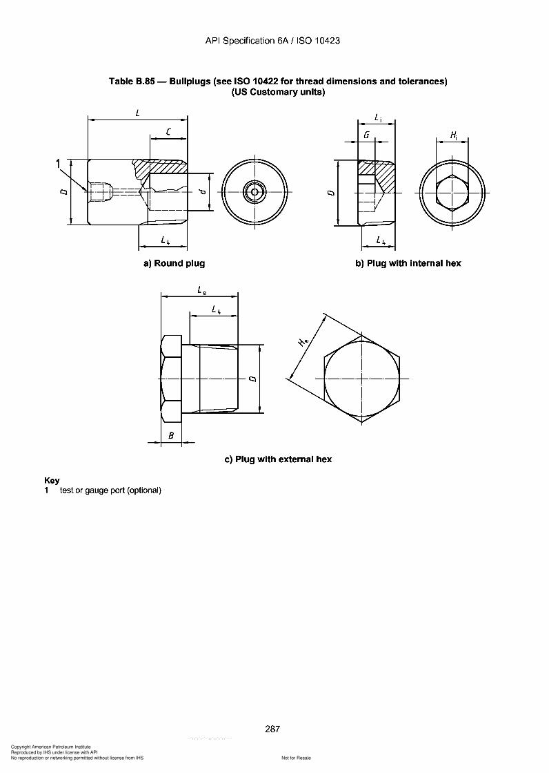
Copyright American Petroleum Institute
Reproduced by IHS under license with API
Not for ResaleNo reproduction or networking permitted without license from IHS
--`,,`,`,-`-`,,`,,`,`,,`---
API Specification 6A / ISO 10423
Table B.85 - Bullplugs (see ISO 10422 for thread dimensions and tolerances)(US Customary units)
L
[ G
1
a) Round plug b) Plug with internal hex
Le
L4
~
)-
-- f--- ----- -t:::l
)-
'----
8
c) Plug with external hex
Key1 test or gauge port (optional)
287
1
Key
API Specification 6A / ISO 10423
Table B.85 - Bullplugs (see ISO 10422 for thread dimensions and tolerances) (US Customary units)
L
[ G
a) Round plug b) Plug with internal hex
L e
L4
~
)-
-- r--- ----- -t:::l
)-
'---
8
c) Plug with external hex
1 test or gauge port (optional)
287
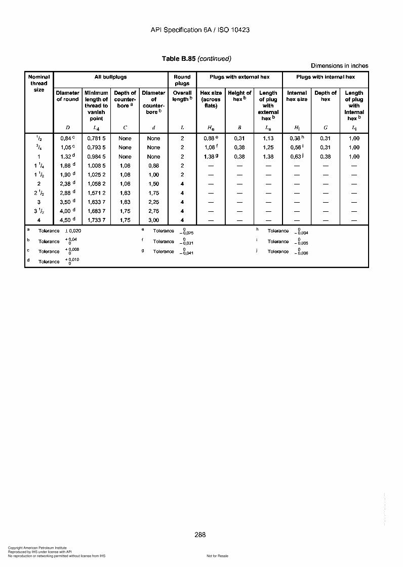
d
Copyright American Petroleum Institute
Reproduced by IHS under license with API
Not for ResaleNo reproduction or networking permitted without license from IHS
--`,,`,`,-`-`,,`,,`,`,,`---
API Specification 6A / ISO 10423
Table B.85 (continued)Dimensions in inches
Nominal All bullplugs Round Plugs with external hex Plugs with internal hexthread plugs
sizeDiameter Minimum Depth of Diameter Overall Hex size Height of Length Internal Depth of Lengthof round length of counter- of length b (across hex b of plug hex size hex of plug
thread to bore a counter- flats) with withvanish bore b external internalpoint hex b hex b
D L4 C d L He B Le Hi G Li
1/2 0,84 c 0,781 5 None None 2 0,88 e 0,31 1,13 0,38 h 0,31 1,00
3/4 1,05 c 0,7935 None None 2 1,06 f 0,38 1,25 0,56 i 0,31 1,00
1 1,32 d 0,9845 None None 2 1,38 9 0,38 1,38 0,63 i 0,38 1,00
1 1/4 1,66 d 1,0085 1,06 0,88 2 - - - - - -1 1/2 1,90 d 1,0252 1,06 1,00 2 - - - - - -
2 2,38 d 1,0582 1,06 1,50 4 - - - - - -
2 1/2 2,88 d 1,571 2 1,63 1,75 4 - - - - - -
3 3,50 d 1,6337 1,63 2,25 4 - - - - - -
3 1/2 4,00 d 1,6837 1,75 2,75 4 - - - - - -
4 4,50 d 1,7337 1,75 3,00 4 - - - - - -
a Tolerance ± 0,020 e Tolerance 0 h Tolerance 0- 0,025 - 0,004
b Tolerance + 0,04 f Tolerance 0 i Tolerance 00 -0,031 - 0,005
c Tolerance + 0,008 9 Tolerance 0 j Tolerance 00 -0,041 - 0,006
d Tolerance + 0,0100
288
API Specification 6A / ISO 10423
Table B.85 (continued) Dimensions in inches
Nominal All bullplugs Round Plugs with external hex Plugs with internal hex thread plugs
size Diameter Minimum Depth of Diameter Overall Hex size Height of Length Internal Depth of Length of round length of counter- of length b (across hex b of plug hex size hex of plug
thread to bore a counter- flats) with with vanish bore b external internal point hex b hex b
D L4 C d L He B Le Hj G Lj
1/2 0,84c 0,781 5 None None 2 0,88 e 0,31 1,13 0,38 h 0,31 1,00
3/4 1,05 c 0,7935 None None 2 1,06 f 0,38 1,25 0,56 j 0,31 1,00
1 1,32 d 0,9845 None None 2 1,38 9 0,38 1,38 0,63 i 0,38 1,00
1 1/4 1,66 d 1,0085 1,06 0,88 2 - - - - - -1 1/2 1,90 d 1,0252 1,06 1,00 2 - - - - - -
2 2,38 d 1,0582 1,06 1,50 4 - - - - - -
21/2 2,88 d 1,571 2 1,63 1,75 4 - - - - - -
3 3,50 d 1,6337 1,63 2,25 4 - - - - - -
3 1/2 4,00 d 1,6837 1,75 2,75 4 - - - - - -
4 4,50 d 1,7337 1,75 3,00 4 - - - - - -
a Tolerance ± 0,020 e Tolerance 0 h Tolerance 0 - 0,025 - 0,004
b Tolerance + 0,04 f Tolerance 0 i Tolerance 0 0 -0,031 - 0,005
c Tolerance + 0,008 9 Tolerance 0 j Tolerance 0 0 -0,041 - 0,006
d Tolerance + 0,010 0
288
d
Copyright American Petroleum Institute
Reproduced by IHS under license with API
Not for ResaleNo reproduction or networking permitted without license from IHS
--`,,`,`,-`-`,,`,,`,`,,`---
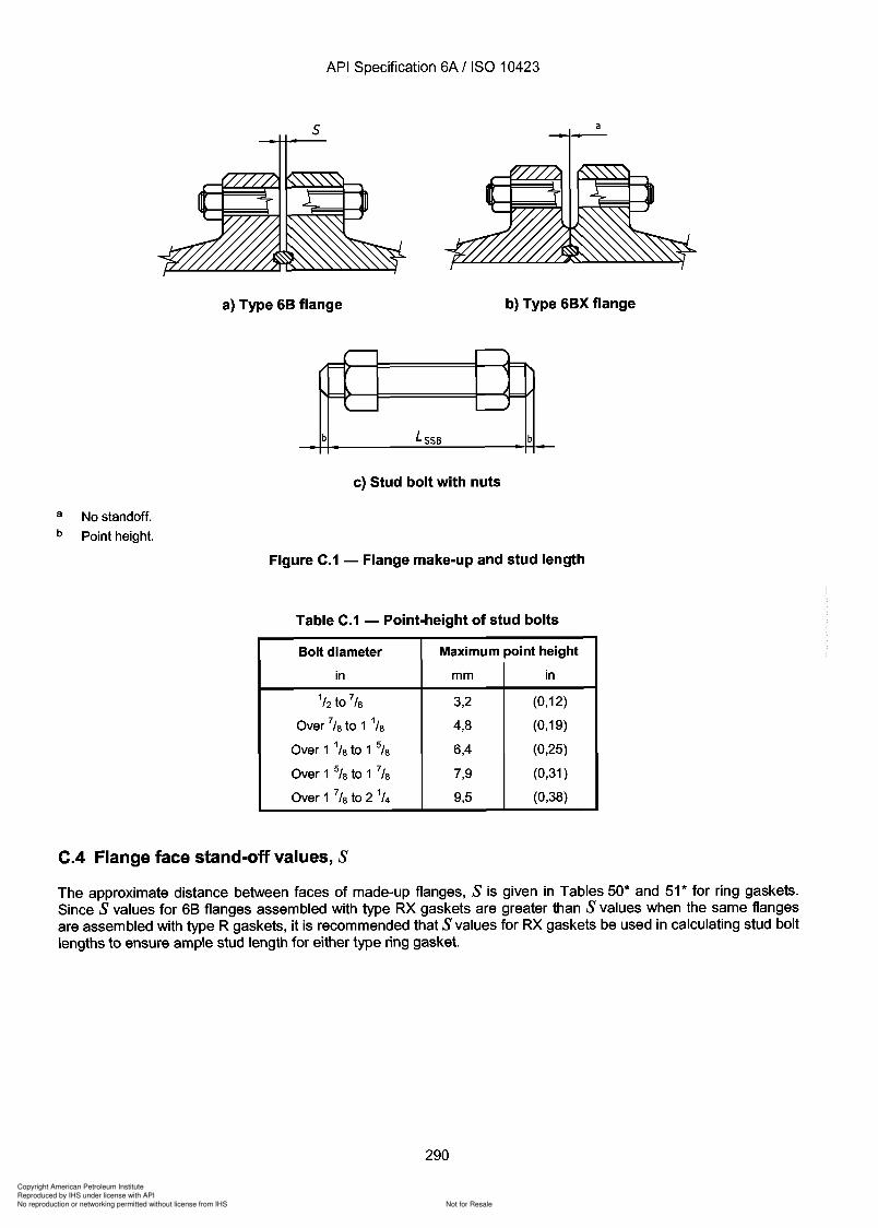
Copyright American Petroleum Institute
Reproduced by IHS under license with API
Not for ResaleNo reproduction or networking permitted without license from IHS
--`,,`,`,-`-`,,`,,`,`,,`---
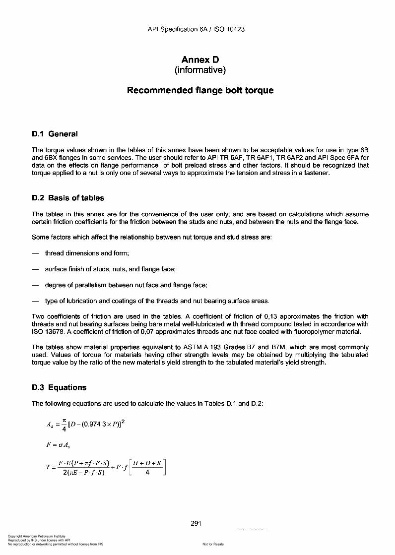
Copyright American Petroleum Institute
Reproduced by IHS under license with API
Not for ResaleNo reproduction or networking permitted without license from IHS
--`,,`,`,-`-`,,`,,`,`,,`---
API Specification 6A / ISO 10423
Annex D(informative)
Recommended flange bolt torque
0.1 General
The torque values shown in the tables of this annex have been shown to be acceptable values for use in type 68and 68X flanges in some services. The user should refer to API TR 6AF, TR 6AF1, TR 6AF2 and API Spec 6FA fordata on the effects on flange performance of bolt preload stress and other factors. It should be recognized thattorque applied to a nut is only one of several ways to approximate the tension and stress in a fastener.
0.2 Basis of tables
The tables in this annex are for the convenience of the user only, and are based on calculations which assumecertain friction coefficients for the friction between the studs and nuts, and between the nuts and the flange face.
Some factors which affect the relationship between nut torque and stud stress are:
thread dimensions and form;
surface finish of studs, nuts, and flange face;
degree of parallelism between nut face and flange face;
type of lubrication and coatings of the threads and nut bearing surface areas.
Two coefficients of friction are used in the tables. A coefficient of friction of 0,13 approximates the friction withthreads and nut bearing surfaces being bare metal well-lubricated with thread compound tested in accordance withISO 13678. A coefficient of friction of 0,07 approximates threads and nut face coated with fluoropolymer material.
The tables show material properties equivalent to ASTM A 193 Grades 87 and 87M, which are most commonlyused. Values of torque for materials having other strength levels may be obtained by multiplying the tabulatedtorque value by the ratio of the new material's yield strength to the tabulated material's yield strength.
0.3 Equations
The following equations are used to calculate the values in Tables D.1 and D.2:
As =~[D-(0,9743xP)]24
T= P·E(P+rtj·E·S) +P.j[H +D+K]2(rtE - P-f ·S) 4
291
API Specification 6A / ISO 10423
Annex D (informative)
Recommended flange bolt torque
0.1 General
The torque values shown in the tables of this annex have been shown to be acceptable values for use in type 68 and 68X flanges in some services. The user should refer to API TR 6AF, TR 6AF1, TR 6AF2 and API Spec 6FA for data on the effects on flange performance of bolt preload stress and other factors. It should be recognized that torque applied to a nut is only one of several ways to approximate the tension and stress in a fastener.
0.2 Basis of tables
The tables in this annex are for the convenience of the user only, and are based on calculations which assume certain friction coefficients for the friction between the studs and nuts, and between the nuts and the flange face.
Some factors which affect the relationship between nut torque and stud stress are:
thread dimensions and form;
surface finish of studs, nuts, and flange face;
degree of parallelism between nut face and flange face;
type of lubrication and coatings of the threads and nut bearing surface areas.
Two coefficients of friction are used in the tables. A coefficient of friction of 0,13 approximates the friction with threads and nut bearing surfaces being bare metal well-lubricated with thread compound tested in accordance with ISO 13678. A coefficient of friction of 0,07 approximates threads and nut face coated with fluoropolymer material.
The tables show material properties equivalent to ASTM A 193 Grades 87 and 87M, which are most commonly used. Values of torque for materials having other strength levels may be obtained by multiplying the tabulated torque value by the ratio of the new material's yield strength to the tabulated material's yield strength.
0.3 Equations
The following equations are used to calculate the values in Tables D.1 and D.2:
As =~[D-(0,9743xP)]2 4
T= F·E(P+rtj·E·S) +F.j[H +D+K] 2(rtE - P-f ·S) 4
291
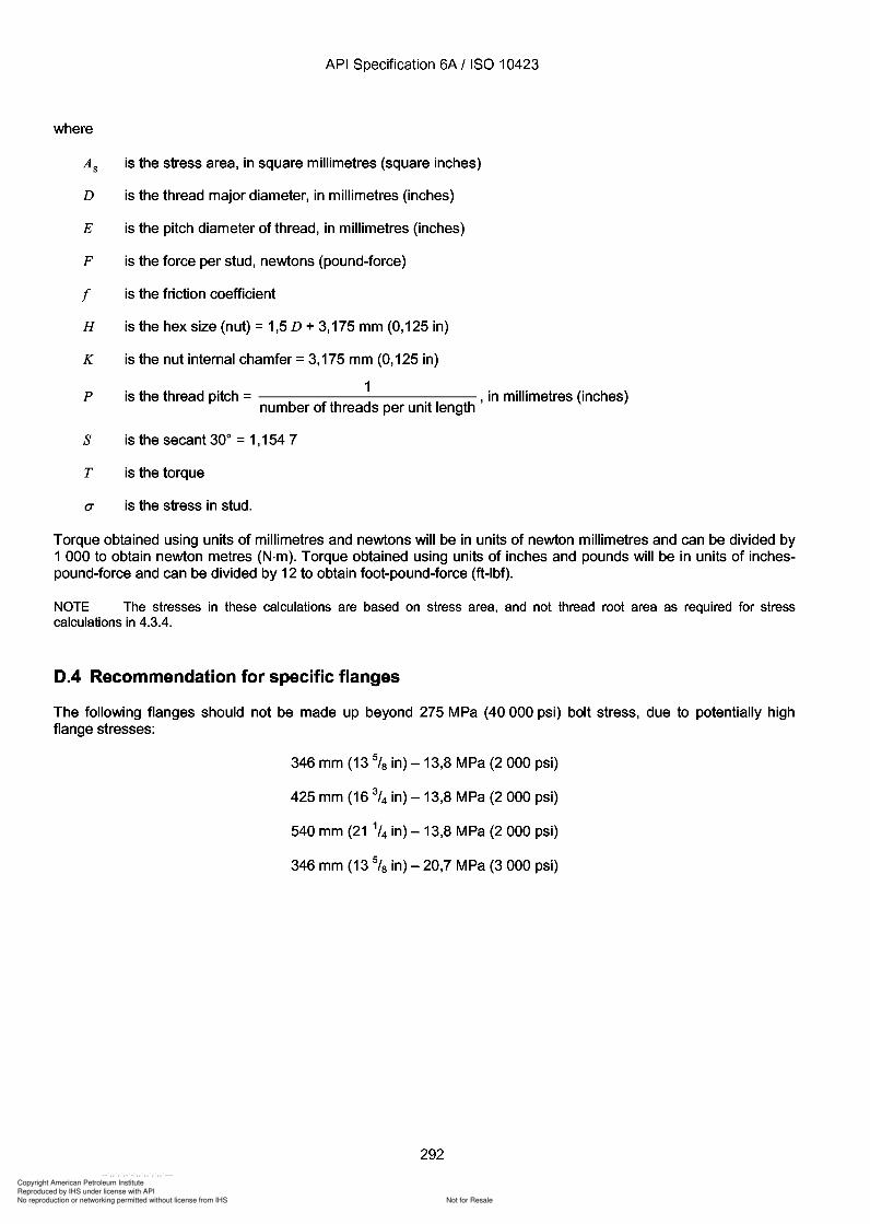
4
Copyright American Petroleum Institute
Reproduced by IHS under license with API
Not for ResaleNo reproduction or networking permitted without license from IHS
--`,,`,`,-`-`,,`,,`,`,,`---
API Specification 6A / ISO 10423
where
is the stress area, in square millimetres (square inches)
D
E
F
rH
K
p
s
T
is the thread major diameter, in millimetres (inches)
is the pitch diameter of thread, in millimetres (inches)
is the force per stud, newtons (pound-force)
is the friction coefficient
is the hex size (nut) =1,5 D + 3,175 mm (0,125 in)
is the nut internal chamfer =3,175 mm (0,125 in)
is the thread pitch = 1 , in millimetres (inches)number of threads per unit length
is the secant 30° =1,154 7
is the torque
is the stress in stud.
Torque obtained using units of millimetres and newtons will be in units of newton millimetres and can be divided by1 000 to obtain newton metres (N·m). Torque obtained using units of inches and pounds will be in units of inchespound-force and can be divided by 12 to obtain foot-pound-force (ft-Ibf).
NOTE The stresses in these calculations are based on stress area, and not thread root area as required for stresscalculations in 4.3.4.
0.4 Recommendation for specific flanges
The following flanges should not be made up beyond 275 MPa (40000 psi) bolt stress, due to potentially highflange stresses:
346 mm (13 5/8 in) - 13,8 MPa (2 000 psi)
425 mm (16 3/4 in) - 13,8 MPa (2 000 psi)
540 mm (21 1/4 in) - 13,8 MPa (2 000 psi)
346 mm (13 5/8 in) - 20,7 MPa (3 000 psi)
292
API Specification 6A / ISO 10423
where
is the stress area, in square millimetres (square inches)
D is the thread major diameter, in millimetres (inches)
E is the pitch diameter of thread, in millimetres (inches)
F is the force per stud, newtons (pound-force)
r is the friction coefficient
H is the hex size (nut) = 1,5 D + 3,175 mm (0,125 in)
K is the nut internal chamfer = 3,175 mm (0,125 in)
p is the thread pitch = 1 , in millimetres (inches) number of threads per unit length
s is the secant 30° = 1,154 7
T is the torque
is the stress in stud.
Torque obtained using units of millimetres and newtons will be in units of newton millimetres and can be divided by 1 000 to obtain newton metres (N·m). Torque obtained using units of inches and pounds will be in units of inchespound-force and can be divided by 12 to obtain foot-pound-force (ft-Ibf).
NOTE The stresses in these calculations are based on stress area, and not thread root area as required for stress calculations in 4.3.4.
0.4 Recommendation for specific flanges
The following flanges should not be made up beyond 275 MPa (40000 psi) bolt stress, due to potentially high flange stresses:
346 mm (13 5/8 in) - 13,8 MPa (2 000 psi)
425 mm (16 3/4 in) - 13,8 MPa (2 000 psi)
540 mm (21 1/4 in) - 13,8 MPa (2 000 psi)
346 mm (13 5/8 in) - 20,7 MPa (3 000 psi)
292
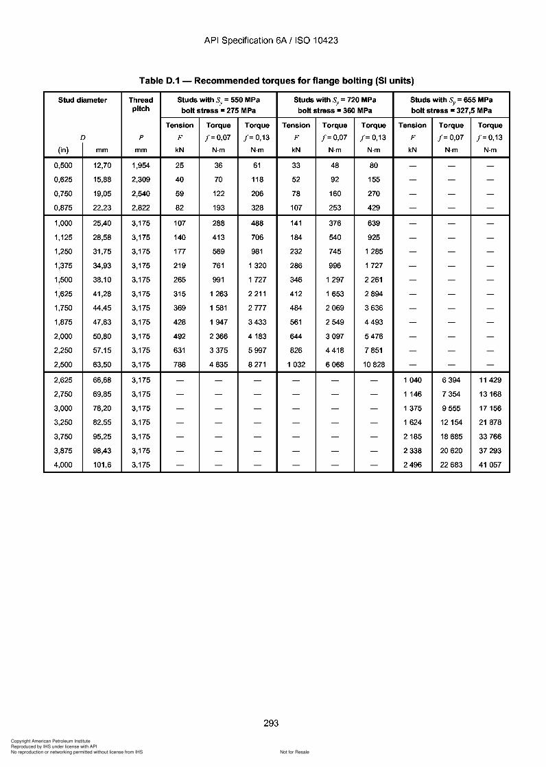
Copyright American Petroleum Institute
Reproduced by IHS under license with API
Not for ResaleNo reproduction or networking permitted without license from IHS
--`,,`,`,-`-`,,`,,`,`,,`---
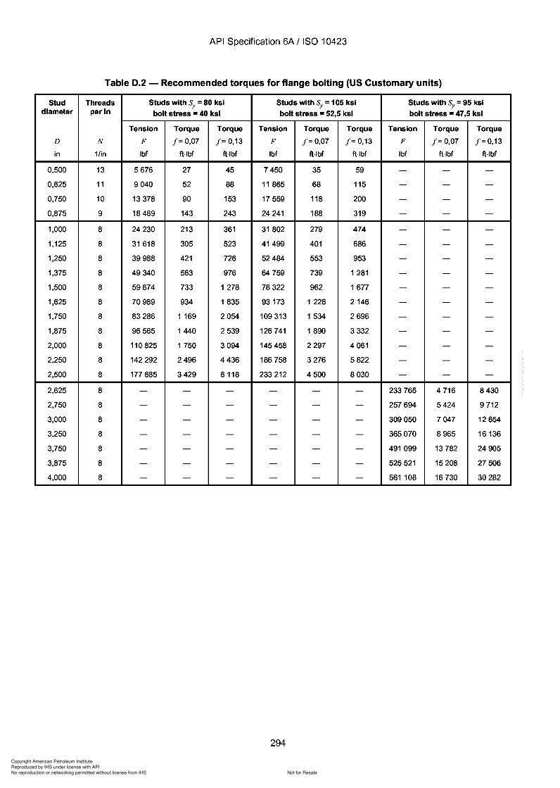
Copyright American Petroleum Institute
Reproduced by IHS under license with API
Not for ResaleNo reproduction or networking permitted without license from IHS
--`,,`,`,-`-`,,`,,`,`,,`---
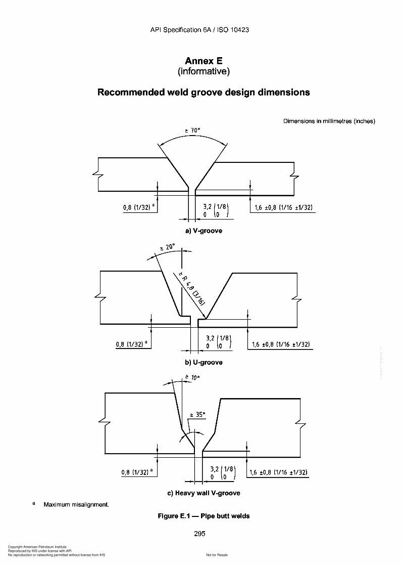
Copyright American Petroleum Institute
Reproduced by IHS under license with API
Not for ResaleNo reproduction or networking permitted without license from IHS
--`,,`,`,-`-`,,`,,`,`,,`---
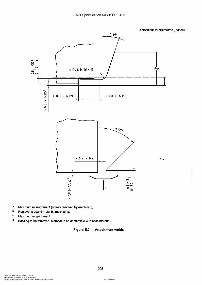
Copyright American Petroleum Institute
Reproduced by IHS under license with API
Not for ResaleNo reproduction or networking permitted without license from IHS
--`,,`,`,-`-`,,`,,`,`,,`---
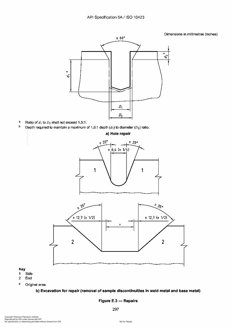
2
Copyright American Petroleum Institute
Reproduced by IHS under license with API
Not for ResaleNo reproduction or networking permitted without license from IHS
--`,,`,`,-`-`,,`,,`,`,,`---
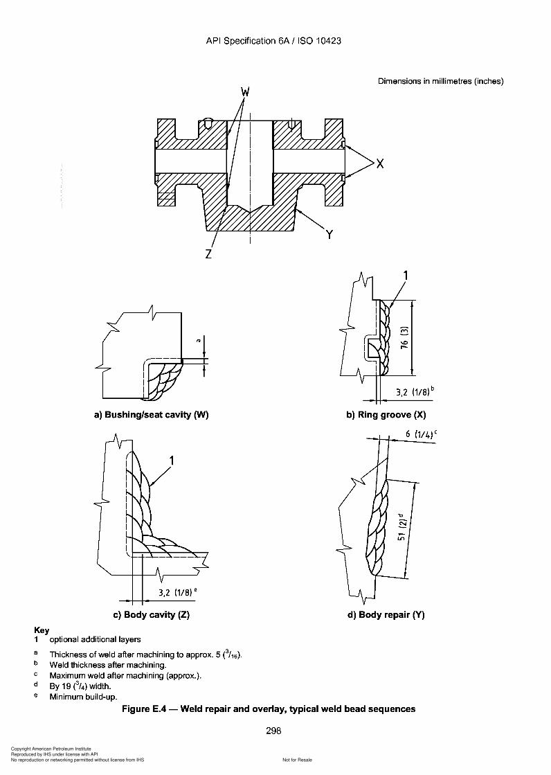
Copyright American Petroleum Institute
Reproduced by IHS under license with API
Not for ResaleNo reproduction or networking permitted without license from IHS
--`,,`,`,-`-`,,`,,`,`,,`---
Copyright American Petroleum Institute
Reproduced by IHS under license with API
Not for ResaleNo reproduction or networking permitted without license from IHS
--`,,`,`,-`-`,,`,,`,`,,`---
API Specification 6A / ISO 10423
Annex F(informative)
Performance verification procedures
F.1 Performance verification - General requirements
F.1.1 Application
F.1.1.1 General
This annex provides performance verification procedures for qualification of equipment specified by thisInternational Standard, which shall be applied if specified by the manufacturer or purchaser.
The performance requirements apply to all products being manufactured and delivered for service (see 4.1). Theperformance verification procedures in this annex are to be applied to designs of products, including designchanges. Verification testing specified in this annex is intended to be performed on prototypes or productionmodels (see also 4.7).
F.1.1.2 Alternative procedures
Other procedures may be used, provided the test requirements of this annex are met or exceeded.
F.1.1.3 Other verification tests
Verification tests that have been completed in accordance with verification testing requirements of API Spec 6A,during its validity, will satisfy the requirements of this annex.
F.1.2 Effect of changes in product
a) Design changes
A design that undergoes a substantive change becomes a new design requIring performance verification. Asubstantive change is a change identified by the manufacturer which affects the performance of the product in theintended service condition. This may include changes in fit, form, function or material.
NOTE Fit, when defined as the geometric relationship between parts, would include the tolerance criteria used during thedesign of a part and its mating parts. Fit, when defined as the state of being adjusted to or shaped for, would include thetolerance criteria used during the design of a seal and its mating parts.
b) Metallic materials
A change in metallic materials may not require new performance verification if the suitability of the new material canbe substantiated by other means.
c) Non-metallic seals
A change in non-metallic materials may not require new performance verification if the suitability of the newmaterial can be substantiated by other means. Substantive changes in the original documented designconfiguration of non-metallic seals resulting in a new design, shall require performance verification in accordancewith F.1.13.
299
API Specification 6A / ISO 10423
Annex F (informative)
Performance verification procedures
F.1 Performance verification - General requirements
F .1.1 Application
F.1.1.1 General
This annex provides performance verification procedures for qualification of equipment specified by this International Standard, which shall be applied if specified by the manufacturer or purchaser.
The performance requirements apply to all products being manufactured and delivered for service (see 4.1). The performance verification procedures in this annex are to be applied to designs of products, including design changes. Verification testing specified in this annex is intended to be performed on prototypes or production models (see also 4.7).
F .1.1.2 Alternative procedures
Other procedures may be used, provided the test requirements of this annex are met or exceeded.
F .1.1.3 Other verification tests
Verification tests that have been completed in accordance with verification testing requirements of API Spec 6A, during its validity, will satisfy the requirements of this annex.
F.1.2 Effect of changes in product
a) Design changes
A design that undergoes a substantive change becomes a new design requIring performance verification. A substantive change is a change identified by the manufacturer which affects the performance of the product in the intended service condition. This may include changes in fit, form, function or material.
NOTE Fit, when defined as the geometric relationship between parts, would include the tolerance criteria used during the design of a part and its mating parts. Fit, when defined as the state of being adjusted to or shaped for, would include the tolerance criteria used during the design of a seal and its mating parts.
b) Metallic materials
A change in metallic materials may not require new performance verification if the suitability of the new material can be substantiated by other means.
c) Non-metallic seals
A change in non-metallic materials may not require new performance verification if the suitability of the new material can be substantiated by other means. Substantive changes in the original documented design configuration of non-metallic seals resulting in a new design, shall require performance verification in accordance with F.1.13.
299
Copyright American Petroleum Institute
Reproduced by IHS under license with API
Not for ResaleNo reproduction or networking permitted without license from IHS
--`,,`,`,-`-`,,`,,`,`,,`---
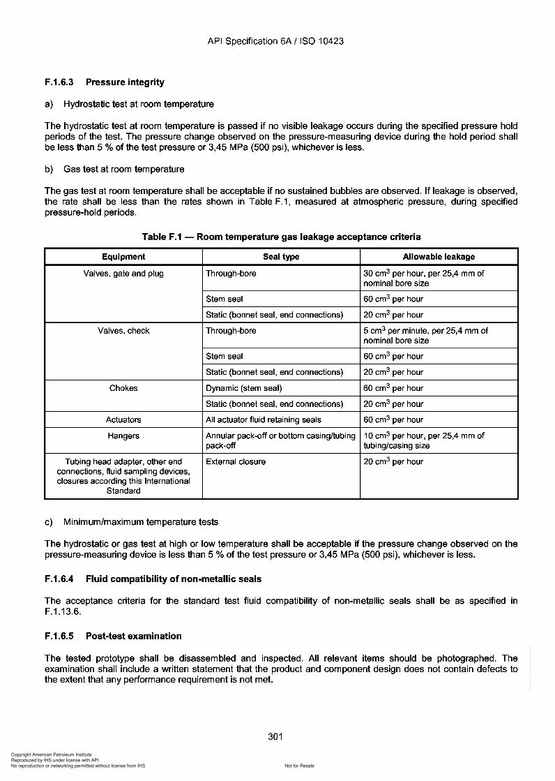
Copyright American Petroleum Institute
Reproduced by IHS under license with API
Not for ResaleNo reproduction or networking permitted without license from IHS
--`,,`,`,-`-`,,`,,`,`,,`---
API Specification 6A / ISO 10423
F.1.6.3 Pressure integrity
a) Hydrostatic test at room temperature
The hydrostatic test at room temperature is passed if no visible leakage occurs during the specified pressure holdperiods of the test. The pressure change observed on the pressure-measuring device during the hold period shallbe less than 5 % of the test pressure or 3,45 MPa (500 psi), whichever is less.
b) Gas test at room temperature
The gas test at room temperature shall be acceptable if no sustained bubbles are observed. If leakage is observed,the rate shall be less than the rates shown in Table F.1, measured at atmospheric pressure, during specifiedpressure-hold periods.
Table F.1 - Room temperature gas leakage acceptance criteria
Equipment Seal type Allowable leakage
Valves, gate and plug Through-bore 30 cm3 per hour, per 25,4 mm ofnominal bore size
Stem seal 60 cm3 per hour
Static (bonnet seal, end connections) 20 cm3 per hour
Valves, check Through-bore 5 cm3 per minute, per 25,4 mm ofnominal bore size
Stem seal 60 cm3 per hour
Static (bonnet seal, end connections) 20 cm3 per hour
Chokes Dynamic (stem seal) 60 cm3 per hour
Static (bonnet seal, end connections) 20 cm3 per hour
Actuators All actuator fluid retaining seals 60 cm3 per hour
Hangers Annular pack-off or bottom casing/tubing 10 cm3 per hour, per 25,4 mm ofpack-off tubing/casing size
Tubing head adapter, other end External closure 20 cm3 per hourconnections, fluid sampling devices,closures according this International
Standard
c) Minimum/maximum temperature tests
The hydrostatic or gas test at high or low temperature shall be acceptable if the pressure change observed on thepressure-measuring device is less than 5 % of the test pressure or 3,45 MPa (500 psi), whichever is less.
F.1.6.4 Fluid compatibility of non-metallic seals
The acceptance criteria for the standard test fluid compatibility of non-metallic seals shall be as specified inF.1.13.6.
F.1.6.5 Post-test examination
The tested prototype shall be disassembled and inspected. All relevant items should be photographed. Theexamination shall include a written statement that the product and component design does not contain defects tothe extent that any performance requirement is not met.
301
API Specification 6A / ISO 10423
F.1.6.3 Pressure integrity
a) Hydrostatic test at room temperature
The hydrostatic test at room temperature is passed if no visible leakage occurs during the specified pressure hold periods of the test. The pressure change observed on the pressure-measuring device during the hold period shall be less than 5 % of the test pressure or 3,45 MPa (500 psi), whichever is less.
b) Gas test at room temperature
The gas test at room temperature shall be acceptable if no sustained bubbles are observed. If leakage is observed, the rate shall be less than the rates shown in Table F.1, measured at atmospheric pressure, during specified pressure-hold periods.
Table F.1 - Room temperature gas leakage acceptance criteria
Equipment Seal type Allowable leakage
Valves, gate and plug Through-bore 30 cm3 per hour, per 25,4 mm of nominal bore size
Stem seal 60 cm3 per hour
Static (bonnet seal, end connections) 20 cm3 per hour
Valves, check Through-bore 5 cm3 per minute, per 25,4 mm of nominal bore size
Stem seal 60 cm3 per hour
Static (bonnet seal, end connections) 20 cm3 per hour
Chokes Dynamic (stem seal) 60 cm3 per hour
Static (bonnet seal, end connections) 20 cm3 per hour
Actuators All actuator fluid retaining seals 60 cm3 per hour
Hangers Annular pack-off or bottom casing/tubing 10 cm3 per hour, per 25,4 mm of pack-off tubing/casing size
Tubing head adapter, other end External closure 20 cm3 per hour connections, fluid sampling devices, closures according this International
Standard
c) Minimum/maximum temperature tests
The hydrostatic or gas test at high or low temperature shall be acceptable if the pressure change observed on the pressure-measuring device is less than 5 % of the test pressure or 3,45 MPa (500 psi), whichever is less.
F.1.6.4 Fluid compatibility of non-metallic seals
The acceptance criteria for the standard test fluid compatibility of non-metallic seals shall be as specified in F.1.13.6.
F .1.6.5 Post-test examination
The tested prototype shall be disassembled and inspected. All relevant items should be photographed. The examination shall include a written statement that the product and component design does not contain defects to the extent that any performance requirement is not met.
301
Copyright American Petroleum Institute
Reproduced by IHS under license with API
Not for ResaleNo reproduction or networking permitted without license from IHS
--`,,`,`,-`-`,,`,,`,`,,`---
303
Copyright American Petroleum Institute
Reproduced by IHS under license with API
Not for ResaleNo reproduction or networking permitted without license from IHS
--`,,`,`,-`-`,,`,,`,`,,`---
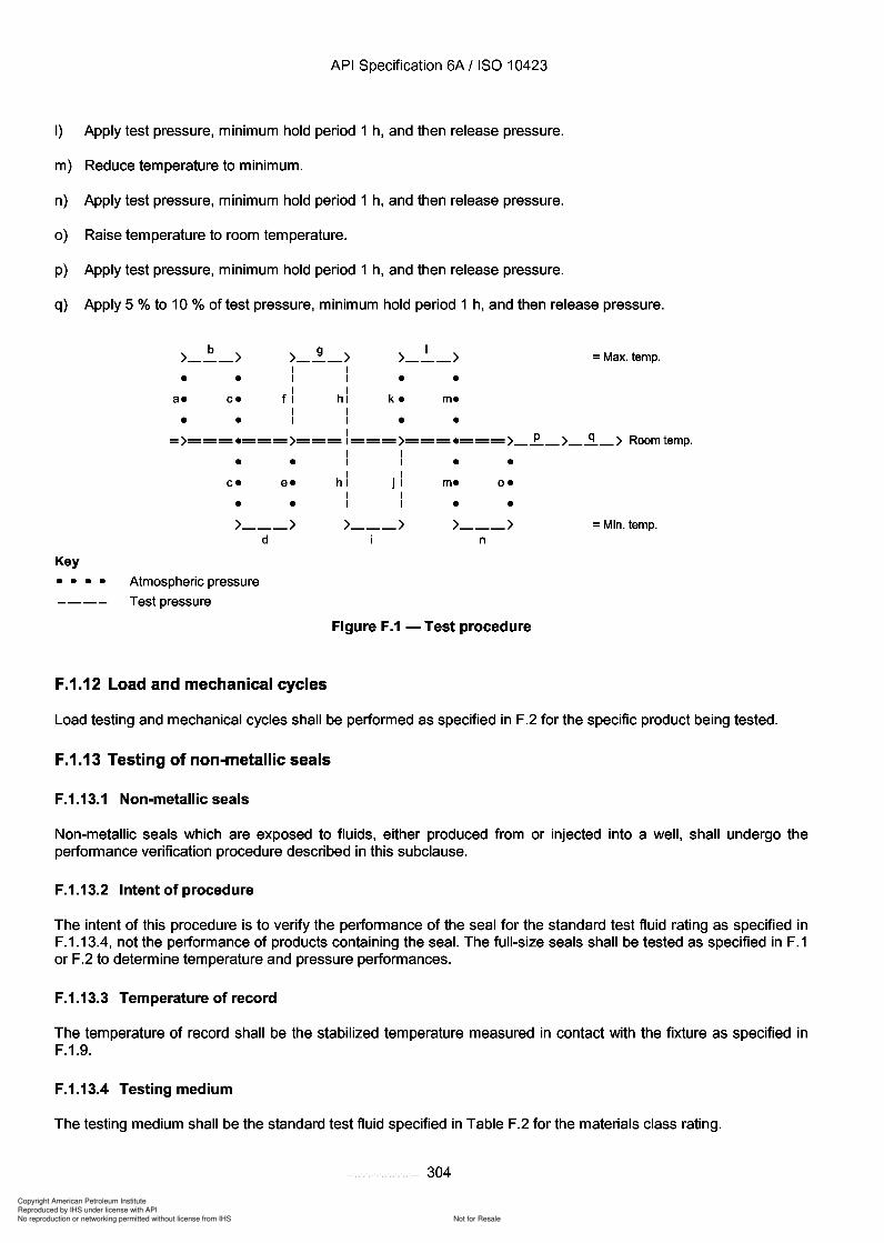
Copyright American Petroleum Institute
Reproduced by IHS under license with API
Not for ResaleNo reproduction or networking permitted without license from IHS
--`,,`,`,-`-`,,`,,`,`,,`---
API Specification 6A / ISO 10423
I) Apply test pressure, minimum hold period 1 h, and then release pressure.
m) Reduce temperature to minimum.
n) Apply test pressure, minimum hold period 1 h, and then release pressure.
0) Raise temperature to room temperature.
p) Apply test pressure, minimum hold period 1 h, and then release pressure.
q) Apply 5 % to 10 % of test pressure, minimum hold period 1 h, and then release pressure.
=Max. temp.
•
•o.
•
•
•
•m.
m.
I>--->•
•k.
•
•e.
•
•
•
•C.
C.
b>--->•
•a.
>-~->I II I
f I hiI II I
I= >===.===>=== 1===>===.===>_.E.._>_~_ > Room temp.
I II I
hi. II J II II I
>--->d
>---> >--->n
=Min. temp.
Key
• • •• Atmospheric pressure
---- Test pressure
Figure F.1 - Test procedure
F.1.12 Load and mechanical cycles
Load testing and mechanical cycles shall be performed as specified in F.2 for the specific product being tested.
F.1.13 Testing of non-metallic seals
F.1.13.1 Non-metallic seals
Non-metallic seals which are exposed to fluids, either produced from or injected into a well, shall undergo theperformance verification procedure described in this subclause.
F.1.13.2 Intent of procedure
The intent of this procedure is to verify the performance of the seal for the standard test fluid rating as specified inF.1.13.4, not the performance of products containing the seal. The full-size seals shall be tested as specified in F.1or F.2 to determine temperature and pressure performances.
F.1.13.3 Temperature of record
The temperature of record shall be the stabilized temperature measured in contact with the fixture as specified inF.1.9.
F.1.13.4 Testing medium
The testing medium shall be the standard test fluid specified in Table F.2 for the materials class rating.
304
API Specification 6A / ISO 10423
I) Apply test pressure, minimum hold period 1 h, and then release pressure.
m) Reduce temperature to minimum.
n) Apply test pressure, minimum hold period 1 h, and then release pressure.
0) Raise temperature to room temperature.
p) Apply test pressure, minimum hold period 1 h, and then release pressure.
q) Apply 5 % to 10 % of test pressure, minimum hold period 1 h, and then release pressure.
b >---> • •
a. c.
• •
>-~-> I I I I
f I hi I I I I
I >---> • •
k. m.
• •
= Max. temp.
I = >===.=== >=== 1=== >=== .=== >_.E.._ >_~_ > Room temp.
Key
• • c. e.
• • >--->
d
• • •• Atmospheric pressure
---- Test pressure
F.1.12 Load and mechanical cycles
I I I I
hi. I I J I I I I I
>--->
• • m. o.
• • >--->
n
Figure F.1 - Test procedure
= Min. temp.
Load testing and mechanical cycles shall be performed as specified in F.2 for the specific product being tested.
F.1.13 Testing of non-metallic seals
F .1.13.1 Non-metallic seals
Non-metallic seals which are exposed to fluids, either produced from or injected into a well, shall undergo the performance verification procedure described in this subclause.
F.1.13.2 Intent of procedure
The intent of this procedure is to verify the performance of the seal for the standard test fluid rating as specified in F.1.13.4, not the performance of products containing the seal. The full-size seals shall be tested as specified in F.1 or F.2 to determine temperature and pressure performances.
F .1.13.3 Temperature of record
The temperature of record shall be the stabilized temperature measured in contact with the fixture as specified in F.1.9.
F.1.13.4 Testing medium
The testing medium shall be the standard test fluid specified in Table F.2 for the materials class rating.
304
Copyright American Petroleum Institute
Reproduced by IHS under license with API
Not for ResaleNo reproduction or networking permitted without license from IHS
--`,,`,`,-`-`,,`,,`,`,,`---
Copyright American Petroleum Institute
Reproduced by IHS under license with API
Not for ResaleNo reproduction or networking permitted without license from IHS
--`,,`,`,-`-`,,`,,`,`,,`---
Copyright American Petroleum Institute
Reproduced by IHS under license with API
Not for ResaleNo reproduction or networking permitted without license from IHS
--`,,`,`,-`-`,,`,,`,`,,`---
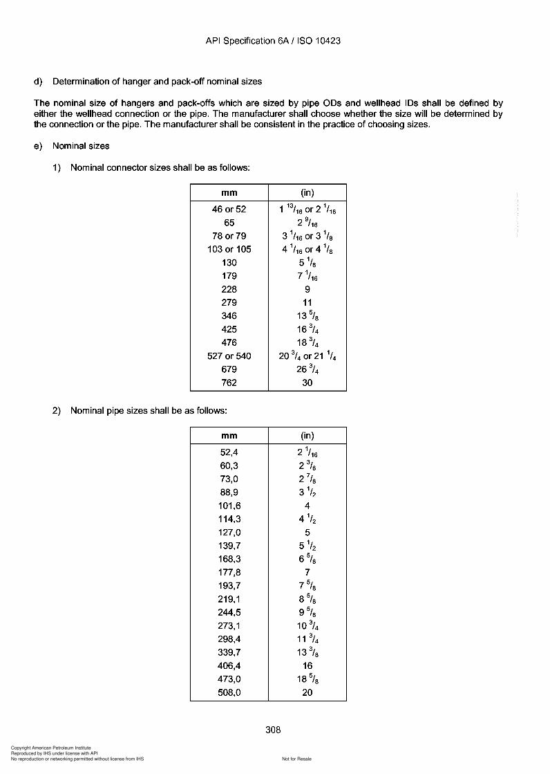
308
Copyright American Petroleum Institute
Reproduced by IHS under license with API
Not for ResaleNo reproduction or networking permitted without license from IHS
--`,,`,`,-`-`,,`,,`,`,,`---
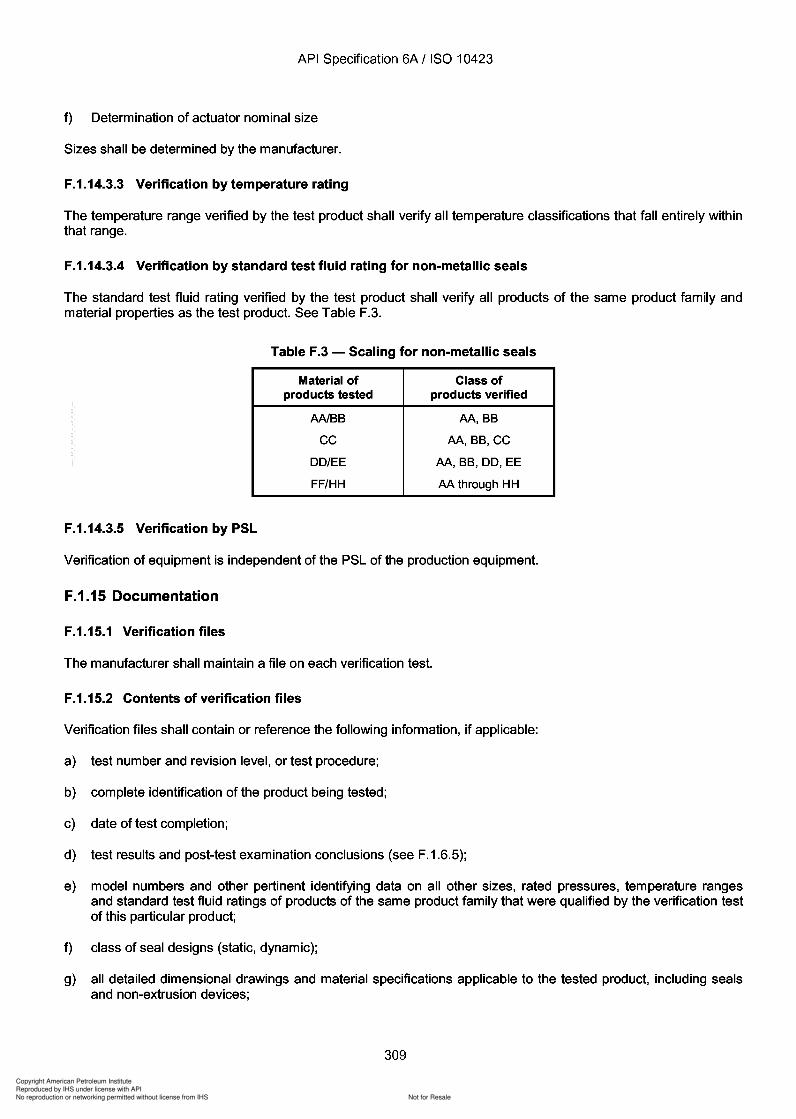
Copyright American Petroleum Institute
Reproduced by IHS under license with API
Not for ResaleNo reproduction or networking permitted without license from IHS
--`,,`,`,-`-`,,`,,`,`,,`---
Copyright American Petroleum Institute
Reproduced by IHS under license with API
Not for ResaleNo reproduction or networking permitted without license from IHS
--`,,`,`,-`-`,,`,,`,`,,`---
Copyright American Petroleum Institute
Reproduced by IHS under license with API
Not for ResaleNo reproduction or networking permitted without license from IHS
--`,,`,`,-`-`,,`,,`,`,,`---
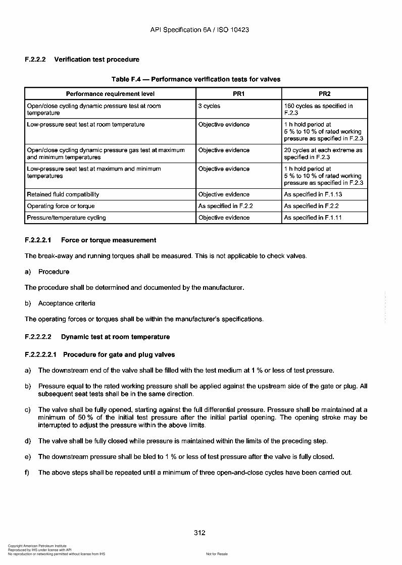
Copyright American Petroleum Institute
Reproduced by IHS under license with API
Not for ResaleNo reproduction or networking permitted without license from IHS
--`,,`,`,-`-`,,`,,`,`,,`---
Copyright American Petroleum Institute
Reproduced by IHS under license with API
Not for ResaleNo reproduction or networking permitted without license from IHS
--`,,`,`,-`-`,,`,,`,`,,`---
Copyright American Petroleum Institute
Reproduced by IHS under license with API
Not for ResaleNo reproduction or networking permitted without license from IHS
--`,,`,`,-`-`,,`,,`,`,,`---
Copyright American Petroleum Institute
Reproduced by IHS under license with API
Not for ResaleNo reproduction or networking permitted without license from IHS
--`,,`,`,-`-`,,`,,`,`,,`---
API Specification 6A / ISO 10423
F.2.3.3.9 Gas seat test at minimum rated temperature
This shall be carried out in accordance with F.2.3.3.5 except at minimum rated temperature.
F.2.3.3.10 Low-pressure seat test at minimum rated temperature
This shall be carried out in accordance with F.2.3.3.6 except at minimum rated temperature.
F.2.3.3.11 Body pressure/temperature cycles
Perform steps F.1.11.3 e) through F.1.11.3 0). Gate and plug valves shall be partially open.
F.2.3.3.12 Body pressure holding test at room temperature
Perform step F.1.11.3 p), but do not release pressure. Gate and plug valves shall be partially open.
F.2.3.3.13 Gas seat test at room temperature
At the end of the hold period of F.2.3.3.12, the valve shall be closed. Rated working pressure shall be maintainedon the upstream side of the gate or plug and released on the downstream side. Check valves shall be tested fromthe downstream side. There shall be one pressure-holding period of not less than 15 min duration. Pressure is thenreleased.
F.2.3.3.14 Body low-pressure holding test
Perform step F.1.11.3 q). Gate and plug valves shall be partially open.
F.2.3.3.15 Low-pressure seat test at room temperature
Valves shall be subjected to a differential pressure of no less than 5 % nor more than 10 % of the rated workingpressure. One hold period of a minimum of 1 h duration shall be applied (in each direction, for bidirectional valves).Check valves shall have the low-pressure seat test pressure applied on the downstream end of the valve, with theopposite end vented to atmosphere.
F.2.3.3.16 Final force or torque measurement
This shall be carried out in accordance with F.2.2.2.1.
F.2.4 Performance verification for PR1 actuators (see Table F.5)
Actuators including electric actuators shall be subjected to a functional test to demonstrate proper assembly andoperation. Test medium for pneumatic actuators shall be a gas. Test medium for hydraulic actuators shall be asuitable hydraulic fluid. The tests shall be performed at room temperature.
The following test procedure is in lieu of the pressure/temperature test of F.1.11.
The actuator seals shall be pressure-tested in two steps by applying pressures of 20 % and 100 % of the ratedworking pressure of the actuator. The minimum hold period for each pressure test shall be: 10 min at 20 %pressure and 5 min at 100 % pressure for pneumatic actuators; 3 min at each pressure test for hydraulic actuators.The actuator seal test above shall be repeated a minimum of three times.
315
API Specification 6A / ISO 10423
F.2.3.3.9 Gas seat test at minimum rated temperature
This shall be carried out in accordance with F.2.3.3.5 except at minimum rated temperature.
F.2.3.3.10 Low-pressure seat test at minimum rated temperature
This shall be carried out in accordance with F.2.3.3.6 except at minimum rated temperature.
F .2.3.3.11 Body pressure/temperature cycles
Perform steps F.1.11.3 e) through F.1.11.3 0). Gate and plug valves shall be partially open.
F.2.3.3.12 Body pressure holding test at room temperature
Perform step F.1.11.3 p), but do not release pressure. Gate and plug valves shall be partially open.
F.2.3.3.13 Gas seat test at room temperature
At the end of the hold period of F.2.3.3.12, the valve shall be closed. Rated working pressure shall be maintained on the upstream side of the gate or plug and released on the downstream side. Check valves shall be tested from the downstream side. There shall be one pressure-holding period of not less than 15 min duration. Pressure is then released.
F.2.3.3.14 Body low-pressure holding test
Perform step F.1.11.3 q). Gate and plug valves shall be partially open.
F.2.3.3.1S Low-pressure seat test at room temperature
Valves shall be subjected to a differential pressure of no less than 5 % nor more than 10 % of the rated working pressure. One hold period of a minimum of 1 h duration shall be applied (in each direction, for bidirectional valves). Check valves shall have the low-pressure seat test pressure applied on the downstream end of the valve, with the opposite end vented to atmosphere.
F.2.3.3.16 Final force or torque measurement
This shall be carried out in accordance with F.2.2.2.1.
F.2.4 Performance verification for PR1 actuators (see Table F.5)
Actuators including electric actuators shall be subjected to a functional test to demonstrate proper assembly and operation. Test medium for pneumatic actuators shall be a gas. Test medium for hydraulic actuators shall be a suitable hydraulic fluid. The tests shall be performed at room temperature.
The following test procedure is in lieu of the pressure/temperature test of F.1.11.
The actuator seals shall be pressure-tested in two steps by applying pressures of 20 % and 100 % of the rated working pressure of the actuator. The minimum hold period for each pressure test shall be: 10 min at 20 % pressure and 5 min at 100 % pressure for pneumatic actuators; 3 min at each pressure test for hydraulic actuators. The actuator seal test above shall be repeated a minimum of three times.
315
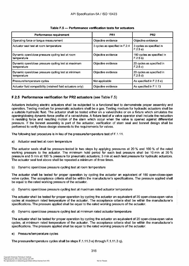
Copyright American Petroleum Institute
Reproduced by IHS under license with API
Not for ResaleNo reproduction or networking permitted without license from IHS
--`,,`,`,-`-`,,`,,`,`,,`---
Copyright American Petroleum Institute
Reproduced by IHS under license with API
Not for ResaleNo reproduction or networking permitted without license from IHS
--`,,`,`,-`-`,,`,,`,`,,`---
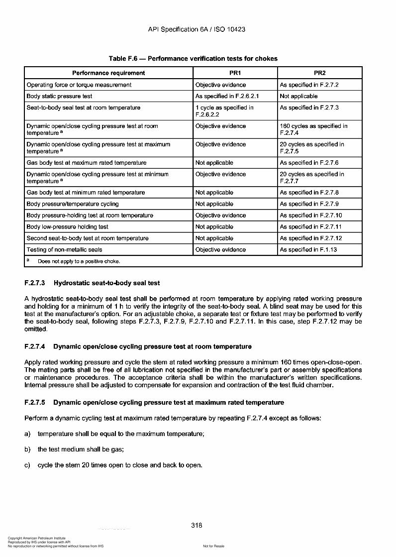
Copyright American Petroleum Institute
Reproduced by IHS under license with API
Not for ResaleNo reproduction or networking permitted without license from IHS
--`,,`,`,-`-`,,`,,`,`,,`---
API Specification 6A / ISO 10423
Table F.6 - Performance verification tests for chokes
Performance requirement PR1 PR2
Operating force or torque measurement Objective evidence As specified in F.2.7.2
Body static pressure test As specified in F.2.6.2.1 Not applicable
Seat-to-body seal test at room temperature 1 cycle as specified in As specified in F.2.7.3F.2.6.2.2
Dynamic open/close cycling pressure test at room Objective evidence 160 cycles as specified intemperature a F.2.7.4
Dynamic open/close cycling pressure test at maximum Objective evidence 20 cycles as specified intemperature a F.2.7.5
Gas body test at maximum rated temperature Not applicable As specified in F.2.7.6
Dynamic open/close cycling pressure test at minimum Objective evidence 20 cycles as specified intemperature a F.2.7.7
Gas body test at minimum rated temperature Not applicable As specified in F.2.7.8
Body pressure/temperature cycling Not applicable As specified in F.2.7.9
Body pressure-holding test at room temperature Objective evidence As specified in F.2.7.1 0
Body low-pressure holding test Not applicable As specified in F.2.7.11
Second seat-to-body test at room temperature Not applicable As specified in F.2.7.12
Testing of non-metallic seals Objective evidence As specified in F.1.13
a Does not apply to a positive choke.
F.2.7.3 Hydrostatic seat-to-body seal test
A hydrostatic seat-to-body seal test shall be performed at room temperature by applying rated working pressureand holding for a minimum of 1 h to verify the integrity of the seat-to-body seal. A blind seat may be used for thistest at the manufacturer's option. For an adjustable choke, a separate test or fixture test may be performed to verifythe seat-to-body seal, following steps F.2.7.3, F.2.7.9, F.2.7.10 and F.2.7.11. In this case, step F.2.7.12 may beomitted.
F.2.7.4 Dynamic open/close cycling pressure test at room temperature
Apply rated working pressure and cycle the stem at rated working pressure a minimum 160 times open-close-open.The mating parts shall be free of all lubrication not specified in the manufacturer's part or assembly specificationsor maintenance procedures. The acceptance criteria shall be within the manufacturer's written specifications.Internal pressure shall be adjusted to compensate for expansion and contraction of the test fluid chamber.
F.2.7.5 Dynamic open/close cycling pressure test at maximum rated temperature
Perform a dynamic cycling test at maximum rated temperature by repeating F.2.7.4 except as follows:
a) temperature shall be equal to the maximum temperature;
b) the test medium shall be gas;
c) cycle the stem 20 times open to close and back to open.
318
API Specification 6A / ISO 10423
Table F.6 - Performance verification tests for chokes
Performance requirement PR1 PR2
Operating force or torque measurement Objective evidence As specified in F.2.7.2
Body static pressure test As specified in F .2.6.2.1 Not applicable
Seat-to-body seal test at room temperature 1 cycle as specified in As specified in F.2.7.3 F.2.6.2.2
Dynamic open/close cycling pressure test at room Objective evidence 160 cycles as specified in temperature a F.2.7.4
Dynamic open/close cycling pressure test at maximum Objective evidence 20 cycles as specified in temperature a F.2.7.S
Gas body test at maximum rated temperature Not applicable As specified in F.2.7.6
Dynamic open/close cycling pressure test at minimum Objective evidence 20 cycles as specified in temperature a F.2.7.7
Gas body test at minimum rated temperature Not applicable As specified in F.2.7.8
Body pressure/temperature cycling Not applicable As specified in F.2.7.9
Body pressure-holding test at room temperature Objective evidence As specified in F.2.7.1 0
Body low-pressure holding test Not applicable As specified in F.2.7.11
Second seat-to-body test at room temperature Not applicable As specified in F.2.7.12
Testing of non-metallic seals Objective evidence As specified in F.1.13
a Does not apply to a positive choke.
F.2.7.3 Hydrostatic seat-to-body seal test
A hydrostatic seat-to-body seal test shall be performed at room temperature by applying rated working pressure and holding for a minimum of 1 h to verify the integrity of the seat-to-body seal. A blind seat may be used for this test at the manufacturer's option. For an adjustable choke, a separate test or fixture test may be performed to verify the seat-to-body seal, following steps F.2.7.3, F.2.7.9, F.2.7.10 and F.2.7.11. In this case, step F.2.7.12 may be omitted.
F.2.7.4 Dynamic open/close cycling pressure test at room temperature
Apply rated working pressure and cycle the stem at rated working pressure a minimum 160 times open-close-open. The mating parts shall be free of all lubrication not specified in the manufacturer's part or assembly specifications or maintenance procedures. The acceptance criteria shall be within the manufacturer's written specifications. Internal pressure shall be adjusted to compensate for expansion and contraction of the test fluid chamber.
F.2.7.S Dynamic open/close cycling pressure test at maximum rated temperature
Perform a dynamic cycling test at maximum rated temperature by repeating F.2.7.4 except as follows:
a) temperature shall be equal to the maximum temperature;
b) the test medium shall be gas;
c) cycle the stem 20 times open to close and back to open.
318
Copyright American Petroleum Institute
Reproduced by IHS under license with API
Not for ResaleNo reproduction or networking permitted without license from IHS
--`,,`,`,-`-`,,`,,`,`,,`---
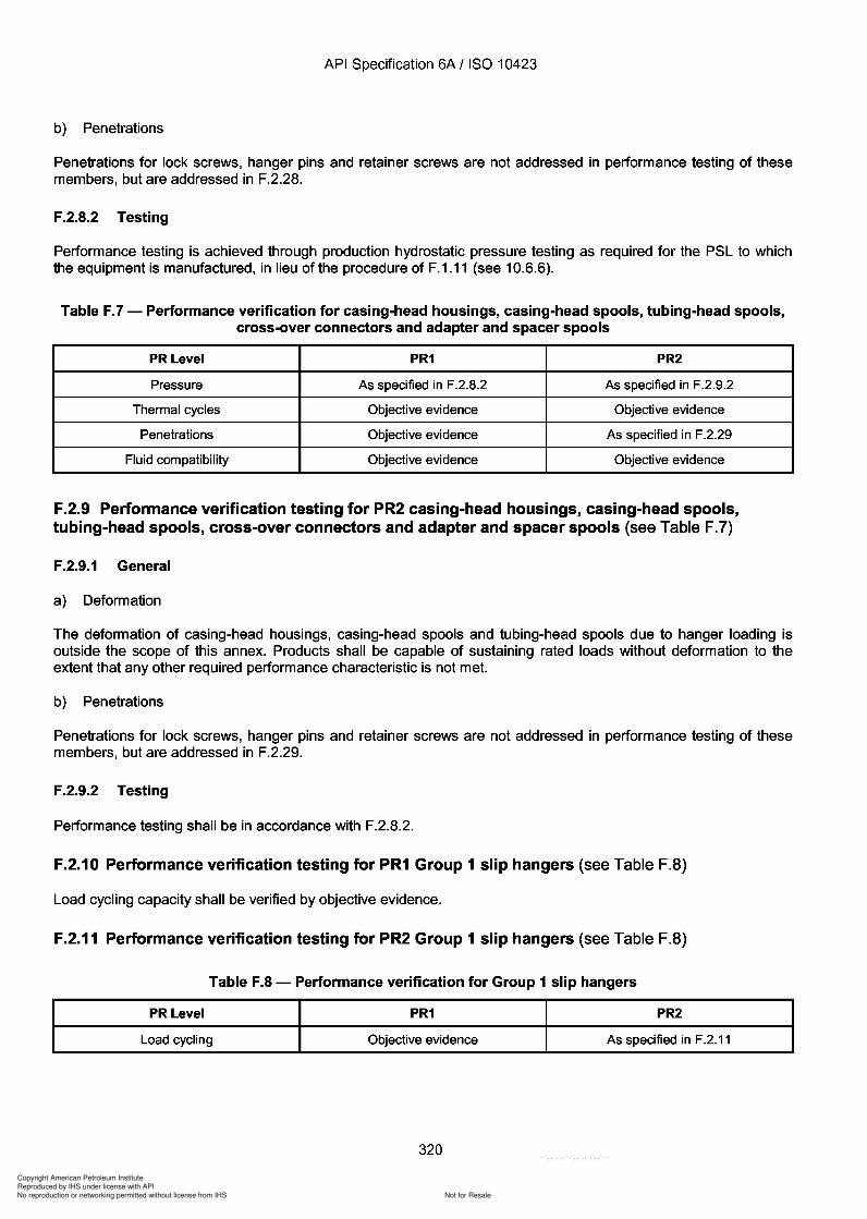
Copyright American Petroleum Institute
Reproduced by IHS under license with API
Not for ResaleNo reproduction or networking permitted without license from IHS
--`,,`,`,-`-`,,`,,`,`,,`---
API Specification 6A / ISO 10423
b) Penetrations
Penetrations for lock screws, hanger pins and retainer screws are not addressed in performance testing of thesemembers, but are addressed in F.2.28.
F.2.8.2 Testing
Performance testing is achieved through production hydrostatic pressure testing as required for the PSL to whichthe equipment is manufactured, in lieu of the procedure of F.1.11 (see 10.6.6).
Table F.7 - Performance verification for casing-head housings, casing-head spools, tubing-head spools,cross-over connectors and adapter and spacer spools
PRLevel PR1 PR2
Pressure As specified in F.2.8.2 As specified in F.2.9.2
Thermal cycles Objective evidence Objective evidence
Penetrations Objective evidence As specified in F.2.29
Fluid compatibility Objective evidence Objective evidence
F.2.9 Performance verification testing for PR2 casing-head housings, casing-head spools,tubing-head spools, cross-over connectors and adapter and spacer spools (see Table F.7)
F.2.9.1 General
a) Deformation
The deformation of casing-head housings, casing-head spools and tubing-head spools due to hanger loading isoutside the scope of this annex. Products shall be capable of sustaining rated loads without deformation to theextent that any other required performance characteristic is not met.
b) Penetrations
Penetrations for lock screws, hanger pins and retainer screws are not addressed in performance testing of thesemembers, but are addressed in F.2.29.
F.2.9.2 Testing
Performance testing shall be in accordance with F.2.8.2.
F.2.10 Performance verification testing for PR1 Group 1 slip hangers (see Table F.B)
Load cycling capacity shall be verified by objective evidence.
F.2.11 Performance verification testing for PR2 Group 1 slip hangers (see Table F.B)
Table F.8 - Performance verification for Group 1 slip hangers
PRLevel PR1 PR2
Load cycling Objective evidence As specified in F.2.11
320
API Specification 6A / ISO 10423
b) Penetrations
Penetrations for lock screws, hanger pins and retainer screws are not addressed in performance testing of these members, but are addressed in F.2.28.
F.2.8.2 Testing
Performance testing is achieved through production hydrostatic pressure testing as required for the PSL to which the equipment is manufactured, in lieu of the procedure of F.1.11 (see 10.6.6).
Table F.7 - Performance verification for casing-head housings, casing-head spools, tubing-head spools, cross-over connectors and adapter and spacer spools
PRLevel PR1 PR2
Pressure As specified in F.2.8.2 As specified in F.2.9.2
Thermal cycles Objective evidence Objective evidence
Penetrations Objective evidence As specified in F.2.29
Fluid compatibility Objective evidence Objective evidence
F.2.9 Performance verification testing for PR2 casing-head housings, casing-head spools, tubing-head spools, cross-over connectors and adapter and spacer spools (see Table F.7)
F.2.9.1 General
a) Deformation
The deformation of casing-head housings, casing-head spools and tubing-head spools due to hanger loading is outside the scope of this annex. Products shall be capable of sustaining rated loads without deformation to the extent that any other required performance characteristic is not met.
b) Penetrations
Penetrations for lock screws, hanger pins and retainer screws are not addressed in performance testing of these members, but are addressed in F.2.29.
F.2.9.2 Testing
Performance testing shall be in accordance with F.2.8.2.
F.2.10 Performance verification testing for PR1 Group 1 slip hangers (see Table F.B)
Load cycling capacity shall be verified by objective evidence.
F.2.11 Performance verification testing for PR2 Group 1 slip hangers (see Table F.B)
Table F.8 - Performance verification for Group 1 slip hangers
PRLevel PR1 PR2
Load cycling Objective evidence As specified in F.2.11
320
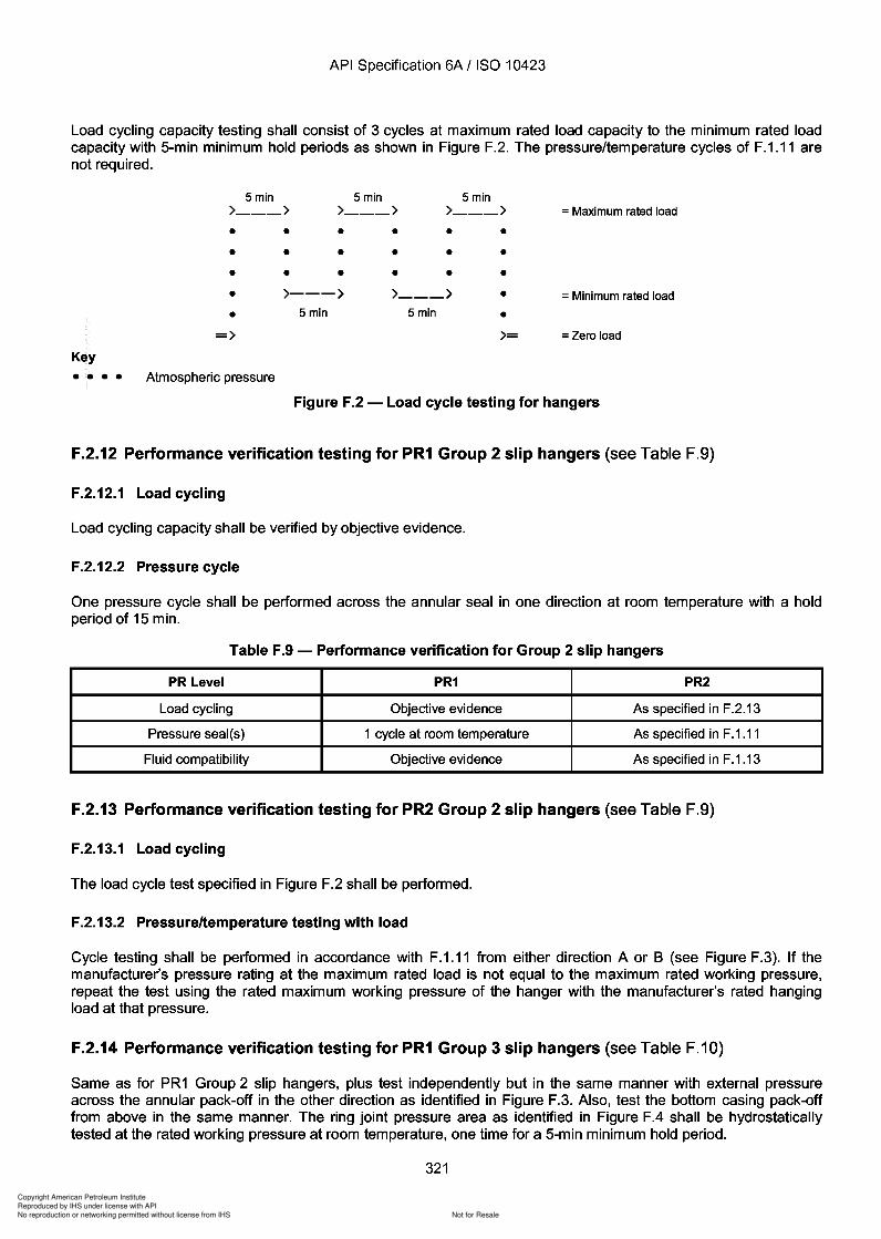
Copyright American Petroleum Institute
Reproduced by IHS under license with API
Not for ResaleNo reproduction or networking permitted without license from IHS
--`,,`,`,-`-`,,`,,`,`,,`---
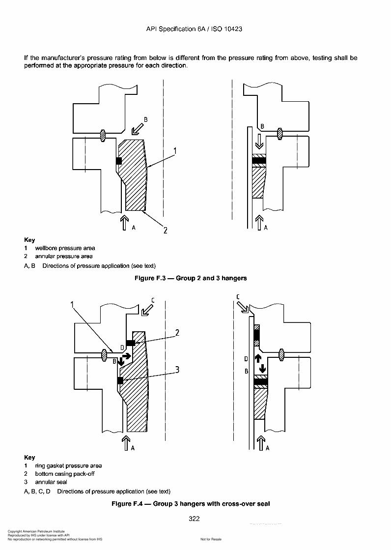
3
3
Copyright American Petroleum Institute
Reproduced by IHS under license with API
Not for ResaleNo reproduction or networking permitted without license from IHS
--`,,`,`,-`-`,,`,,`,`,,`---
API Specification 6A / ISO 10423
If the manufacturer's pressure rating from below is different from the pressure rating from above, testing shall beperformed at the appropriate pressure for each direction.
B
~AKey1 wellbore pressure area2 annular pressure area
A, B Directions of pressure application (see text)
Figure F.3 - Group 2 and 3 hangers
B
~A
o t.,2
3
~A
1
Key1 ring gasket pressure area2 bottom casing pack-off3 annular seal
A, B, C, D Directions of pressure application (see text)
Figure F.4 - Group 3 hangers with cross-over seal
322
API Specification 6A / ISO 10423
If the manufacturer's pressure rating from below is different from the pressure rating from above, testing shall be performed at the appropriate pressure for each direction.
B
~ B
2 ~A Key 1 well bore pressure area 2 annular pressure area
A, B Directions of pressure application (see text)
Figure F.3 - Group 2 and 3 hangers
1
~A Key 1 ring gasket pressure area 2 bottom casing pack-off 3 annular seal
A, B, C, D Directions of pressure application (see text)
2
3 o t ., B
~A
Figure F.4 - Group 3 hangers with cross-over seal
322
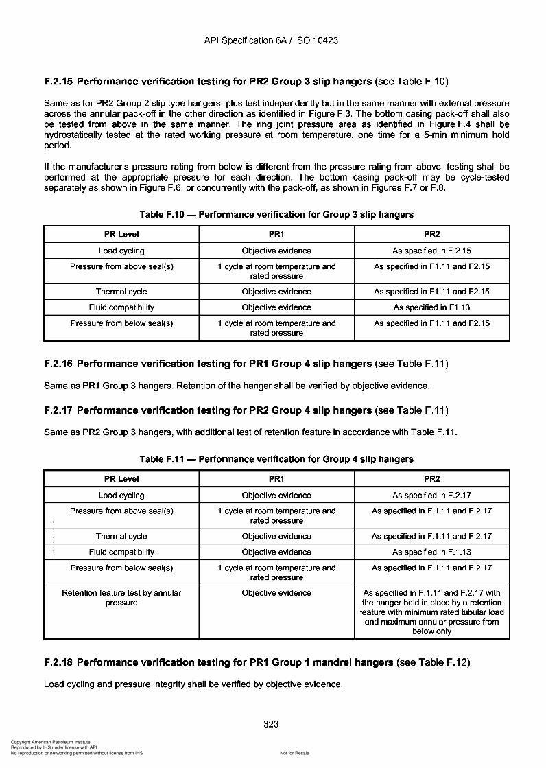
Copyright American Petroleum Institute
Reproduced by IHS under license with API
Not for ResaleNo reproduction or networking permitted without license from IHS
--`,,`,`,-`-`,,`,,`,`,,`---
Copyright American Petroleum Institute
Reproduced by IHS under license with API
Not for ResaleNo reproduction or networking permitted without license from IHS
--`,,`,`,-`-`,,`,,`,`,,`---
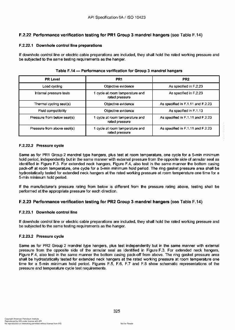
Copyright American Petroleum Institute
Reproduced by IHS under license with API
Not for ResaleNo reproduction or networking permitted without license from IHS
--`,,`,`,-`-`,,`,,`,`,,`---
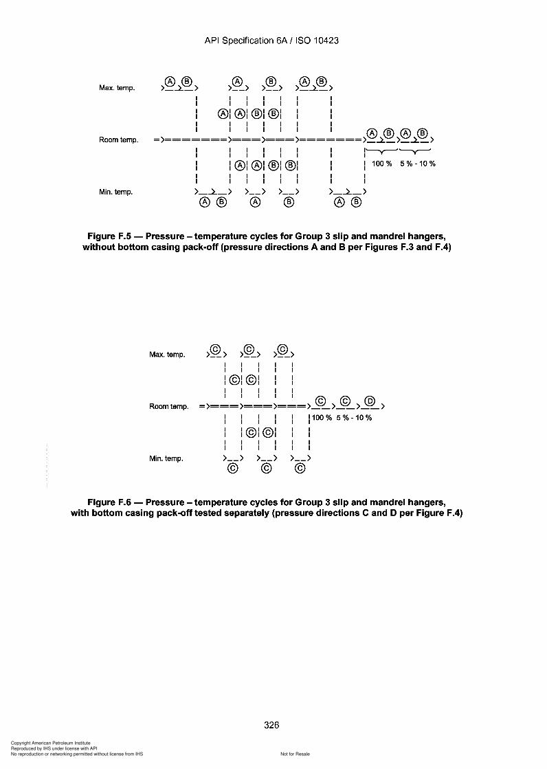
Copyright American Petroleum Institute
Reproduced by IHS under license with API
Not for ResaleNo reproduction or networking permitted without license from IHS
--`,,`,`,-`-`,,`,,`,`,,`---
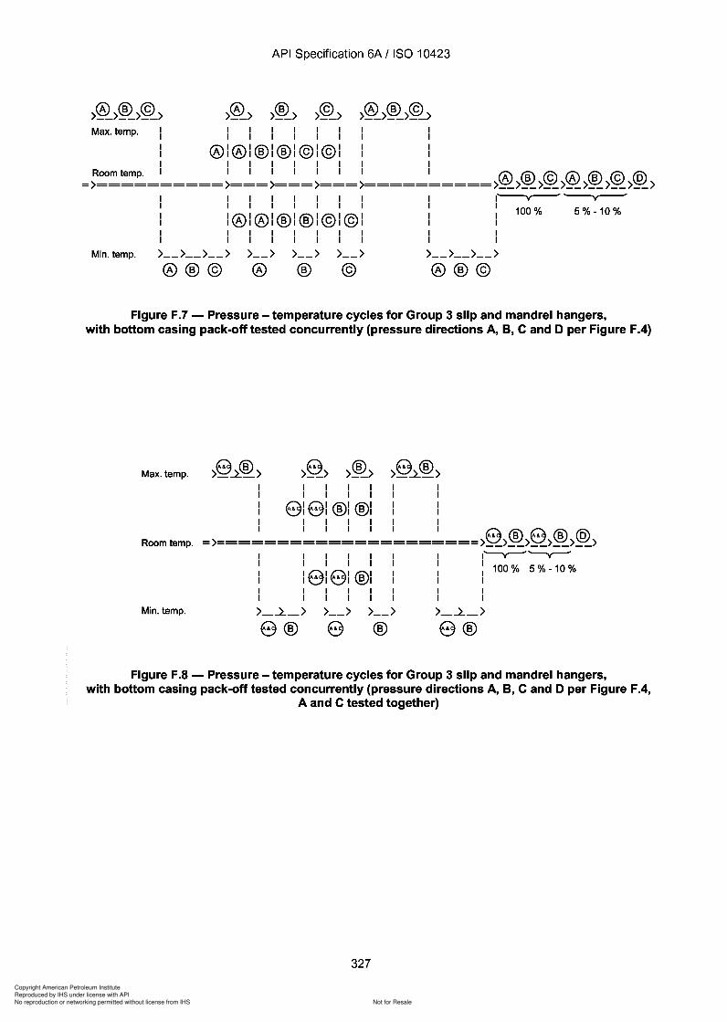
Copyright American Petroleum Institute
Reproduced by IHS under license with API
Not for ResaleNo reproduction or networking permitted without license from IHS
--`,,`,`,-`-`,,`,,`,`,,`---
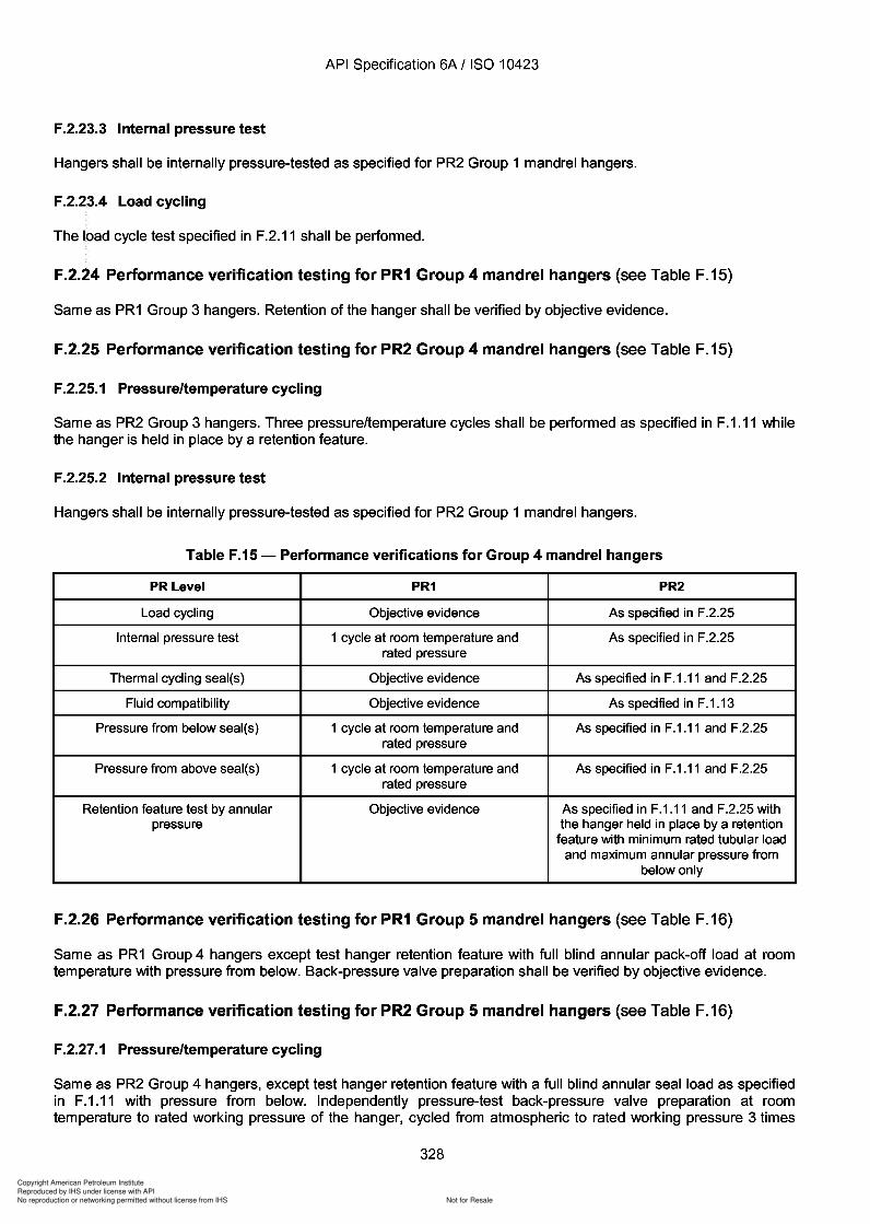
Copyright American Petroleum Institute
Reproduced by IHS under license with API
Not for ResaleNo reproduction or networking permitted without license from IHS
--`,,`,`,-`-`,,`,,`,`,,`---
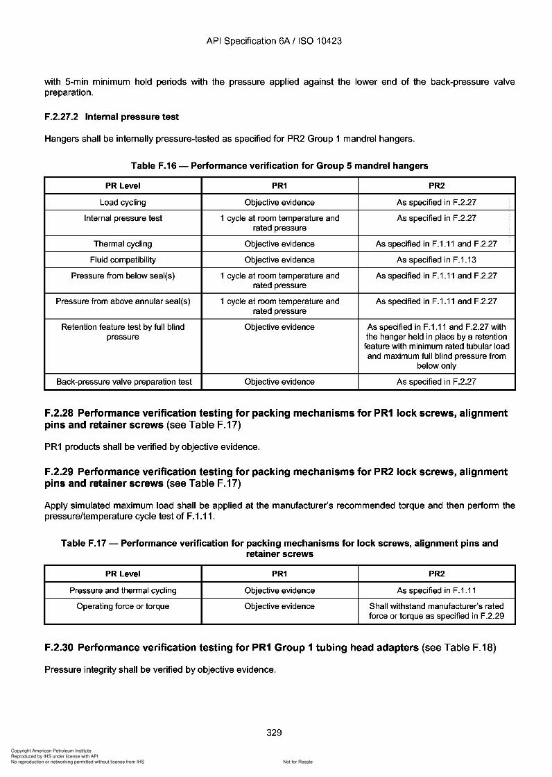
Copyright American Petroleum Institute
Reproduced by IHS under license with API
Not for ResaleNo reproduction or networking permitted without license from IHS
--`,,`,`,-`-`,,`,,`,`,,`---
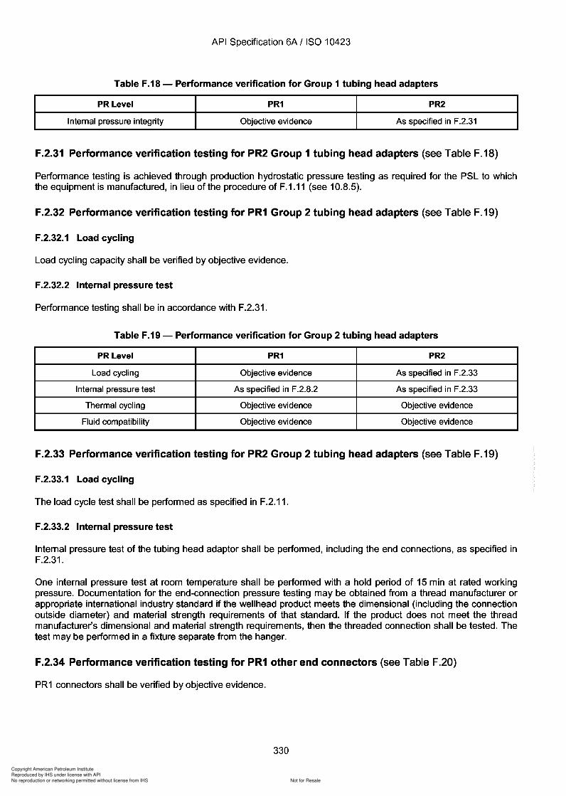
330
Copyright American Petroleum Institute
Reproduced by IHS under license with API
Not for ResaleNo reproduction or networking permitted without license from IHS
--`,,`,`,-`-`,,`,,`,`,,`---
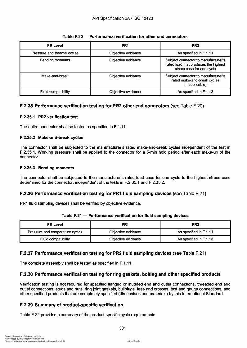
Copyright American Petroleum Institute
Reproduced by IHS under license with API
Not for ResaleNo reproduction or networking permitted without license from IHS
--`,,`,`,-`-`,,`,,`,`,,`---
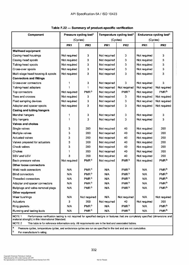
3
3
3
3
3
3
3
3
3
3
3
3
3
3
3
3
3
3
3
3
3
3
Copyright American Petroleum Institute
Reproduced by IHS under license with API
Not for ResaleNo reproduction or networking permitted without license from IHS
--`,,`,`,-`-`,,`,,`,`,,`---
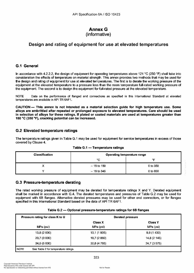
333
Copyright American Petroleum Institute
Reproduced by IHS under license with API
Not for ResaleNo reproduction or networking permitted without license from IHS
--`,,`,`,-`-`,,`,,`,`,,`---
Copyright American Petroleum Institute
Reproduced by IHS under license with API
Not for ResaleNo reproduction or networking permitted without license from IHS
--`,,`,`,-`-`,,`,,`,`,,`---
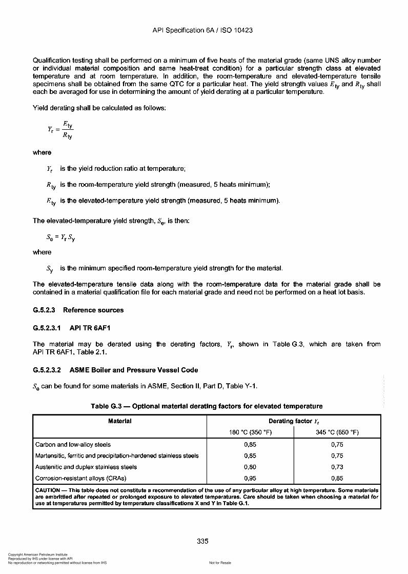
335
Copyright American Petroleum Institute
Reproduced by IHS under license with API
Not for ResaleNo reproduction or networking permitted without license from IHS
--`,,`,`,-`-`,,`,,`,`,,`---
Copyright American Petroleum Institute
Reproduced by IHS under license with API
Not for ResaleNo reproduction or networking permitted without license from IHS
--`,,`,`,-`-`,,`,,`,`,,`---
337
Copyright American Petroleum Institute
Reproduced by IHS under license with API
Not for ResaleNo reproduction or networking permitted without license from IHS
--`,,`,`,-`-`,,`,,`,`,,`---
API Specification 6A / ISO 10423
H.2.4 Vertical bore
If tools have a vertical bore in order to make circulation possible, the drift diameter of the bore should as a minimumbe equal to the drift size for the specified tooljoint or, in case internal profiles are used, according to manufacturer'swritten drift specifications.
The wear bushings shall have an 10 in accordance with Table 68*.
H.2.5 Outside profile
The outside profile of the tools shall be in accordance with the manufacturer's written specification. If possible theoutside profile should be designed to ensure alignment, if needed, and to minimize the risk of hanging up in blowout preventer cavities. The 00 and length of the connections shall, however, be as under H.2.3 above.
H.2.6 Pressure rating
The pressure rating of the tool shall, if applicable, be in accordance with the manufacturer's written specification.
H.3 Materials
H.3.1 General
All tools and parts thereof shall require a written material specification which shall define the following, along withaccept/reject criteria:
mechanical property requirements;
material qualification;
heat-treatment procedure, including cycle time and temperatures with tolerances;
material composition with tolerances;
NOE requirements;
allowable melting practice(s);
hot-working practice(s);
cooling media when heat-treating.
Running tools shall be fabricated from materials which meet the applicable property requirements as specified bythe manufacturer.
H.3.2 Additional requirements
H.3.2.1 General
H.3.2 to H.3.4 only apply to major load-bearing tools such as casing and tubing running tools, cup-type tester andseal assembly setting tools required to transmit torque which is higher than 50 % of the make-up torque of the tool.
337
API Specification 6A / ISO 10423
H.2.4 Vertical bore
If tools have a vertical bore in order to make circulation possible, the drift diameter of the bore should as a minimum be equal to the drift size for the specified tooljoint or, in case internal profiles are used, according to manufacturer's written drift specifications.
The wear bushings shall have an 10 in accordance with Table 68*.
H.2.S Outside profile
The outside profile of the tools shall be in accordance with the manufacturer's written specification. If possible the outside profile should be designed to ensure alignment, if needed, and to minimize the risk of hanging up in blowout preventer cavities. The 00 and length of the connections shall, however, be as under H.2.3 above.
H.2.6 Pressure rating
The pressure rating of the tool shall, if applicable, be in accordance with the manufacturer's written specification.
H.3 Materials
H.3.1 General
All tools and parts thereof shall require a written material specification which shall define the following, along with accept/reject criteria:
mechanical property requirements;
material qualification;
heat-treatment procedure, including cycle time and temperatures with tolerances;
material composition with tolerances;
NOE requirements;
allowable melting practice(s);
hot-working practice(s);
cooling media when heat-treating.
Running tools shall be fabricated from materials which meet the applicable property requirements as specified by the manufacturer.
H.3.2 Additional requirements
H.3.2.1 General
H.3.2 to H.3.4 only apply to major load-bearing tools such as casing and tubing running tools, cup-type tester and seal assembly setting tools required to transmit torque which is higher than 50 % of the make-up torque of the tool.
337
338
Copyright American Petroleum Institute
Reproduced by IHS under license with API
Not for ResaleNo reproduction or networking permitted without license from IHS
--`,,`,`,-`-`,,`,,`,`,,`---
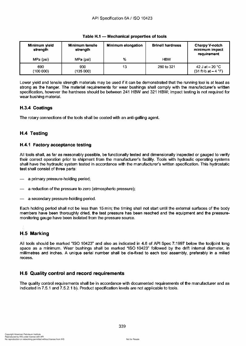
339
Copyright American Petroleum Institute
Reproduced by IHS under license with API
Not for ResaleNo reproduction or networking permitted without license from IHS
--`,,`,`,-`-`,,`,,`,`,,`---
Copyright American Petroleum Institute
Reproduced by IHS under license with API
Not for ResaleNo reproduction or networking permitted without license from IHS
--`,,`,`,-`-`,,`,,`,`,,`---
API Specification 6A / ISO 10423
H.7 Storing and shipping
In addition to the requirements of Clause 9, outside threads shall be protected by a proper storage compound anda metal pressed thread protector or equivalent.
340
API Specification 6A / ISO 10423
H.7 Storing and shipping
In addition to the requirements of Clause 9, outside threads shall be protected by a proper storage compound and a metal pressed thread protector or equivalent.
340
Copyright American Petroleum Institute
Reproduced by IHS under license with API
Not for ResaleNo reproduction or networking permitted without license from IHS
--`,,`,`,-`-`,,`,,`,`,,`---
Copyright American Petroleum Institute
Reproduced by IHS under license with API
Not for ResaleNo reproduction or networking permitted without license from IHS
--`,,`,`,-`-`,,`,,`,`,,`---
API Specification 6A / ISO 10423
b) The circulation piping shall be of sufficient working-pressure rating to withstand the circulation pressure. Thetest-section upstream isolation valve and the pressure-measuring devices, valves, and fittings between it andthe SSV/USV valve being tested, shall be designed for a working pressure of at least that of the valve beingtested. Components of lower pressure ratings shall be protected with appropriate pressure-relief valves.
1.2.3 Apparatus - Circulation system components
1.2.3.1control.
1.2.3.2
Freshwater tank, with a minimum capacity of 1 m3 and equipped with a low level pump shutdown
Sand slurry tank and associated accessories.
A cylindrical, cone-bottom sand slurry tank with a minimum capacity of 1 m3 shall be provided, equipped with anagitation device as required to obtain proper slurry consistency. Sample connections shall be provided in the tankand in the return line to the tank so that representative samples for sand content and viscosity analyses can betaken. High- and low-level shutdowns shall be provided in the tank to signal shutdown of the circulating pumps.Viscosity and sand content shall be determined in accordance with ISO 10414-1.
1.2.3.3 Circulating pumps and controls.
Circulating pumps with drivers and special equipment for pumping the sand slurry and freshwater at the requiredflowrates and pressures shall be installed. At least one pump shall be provided with a variable-speed motor forcirculation flowrate control. Each pump motor shall be provided with a non-resettable elapsed-time meter to monitorpumping duration.
1.2.3.4 Circulation piping and controls.
The circulation piping shall be installed in an arrangement similar to that shown in Figure 1.1. Block valves shall beprovided as indicated in Figure 1.2. The return piping to the sand slurry tank shall be installed in such a manner asto provide agitation to aid in preventing sand accumulation in the bottom of the tank. A choke or other suitablemeans for back-pressure control shall be installed between the circulation pumps and test section as shown inFigure 1.2, and shall be used to control SSV/USV differential pressure to 2,8 MPa (400 psi) during the cycling test.
1.2.3.5 Circulation flow meter, covering a minimum flowrate of 0,3 m3/min (77 US gpm) and providing anoutput signal suitable for strip chart recording.
1.2.3.6 Recording instruments, provided to monitor the following data:
circulation flowrate during all flow testing;
SSV/USV valve upstream test pressure during valve seat leakage test;
differential pressure across the SSV/USV valve being tested during closure test.
Recorders shall be of appropriate ranges and equipped with variable chart speeds to allow resolution of timevarying analog signals.
1.3 PR2 class I SSV/USV valve verification testing
1.3.1 General
To qualify a specific SSV/USV design for PR2 class I, the manufacturer shall test a SSV/USV of the same basicdesign and materials of construction tested in accordance with the PR2 and PSL 2 requirements of thisInternational Standard.
342
API Specification 6A / ISO 10423
b) The circulation piping shall be of sufficient working-pressure rating to withstand the circulation pressure. The test-section upstream isolation valve and the pressure-measuring devices, valves, and fittings between it and the SSV/USV valve being tested, shall be designed for a working pressure of at least that of the valve being tested. Components of lower pressure ratings shall be protected with appropriate pressure-relief valves.
1.2.3 Apparatus - Circulation system components
1.2.3.1 control.
Freshwater tank, with a minimum capacity of 1 m3 and equipped with a low level pump shutdown
1.2.3.2 Sand slurry tank and associated accessories.
A cylindrical, cone-bottom sand slurry tank with a minimum capacity of 1 m3 shall be provided, equipped with an agitation device as required to obtain proper slurry consistency. Sample connections shall be provided in the tank and in the return line to the tank so that representative samples for sand content and viscosity analyses can be taken. High- and low-level shutdowns shall be provided in the tank to signal shutdown of the circulating pumps. Viscosity and sand content shall be determined in accordance with ISO 10414-1.
1.2.3.3 Circulating pumps and controls.
Circulating pumps with drivers and special equipment for pumping the sand slurry and freshwater at the required flowrates and pressures shall be installed. At least one pump shall be provided with a variable-speed motor for circulation flowrate control. Each pump motor shall be provided with a non-resettable elapsed-time meter to monitor pumping duration.
1.2.3.4 Circulation piping and controls.
The circulation piping shall be installed in an arrangement similar to that shown in Figure 1.1. Block valves shall be provided as indicated in Figure 1.2. The return piping to the sand slurry tank shall be installed in such a manner as to provide agitation to aid in preventing sand accumulation in the bottom of the tank. A choke or other suitable means for back-pressure control shall be installed between the circulation pumps and test section as shown in Figure 1.2, and shall be used to control SSV/USV differential pressure to 2,8 MPa (400 psi) during the cycling test.
1.2.3.5 Circulation flow meter, covering a minimum flowrate of 0,3 m3/min (77 US gpm) and providing an output signal suitable for strip chart recording.
1.2.3.6 Recording instruments, provided to monitor the following data:
circulation flowrate during all flow testing;
SSV/USV valve upstream test pressure during valve seat leakage test;
differential pressure across the SSV/USV valve being tested during closure test.
Recorders shall be of appropriate ranges and equipped with variable chart speeds to allow resolution of timevarying analog signals.
1.3 PR2 class I SSV/USV valve verification testing
1.3.1 General
To qualify a specific SSV/USV design for PR2 class I, the manufacturer shall test a SSV/USV of the same basic design and materials of construction tested in accordance with the PR2 and PSL 2 requirements of this International Standard.
342
Copyright American Petroleum Institute
Reproduced by IHS under license with API
Not for ResaleNo reproduction or networking permitted without license from IHS
--`,,`,`,-`-`,,`,,`,`,,`---
API Specification 6A 1 ISO 10423
1.3.2 Verification test requirements
A flanged nominal 2 1/16 , 52 mm 34,5 MPa (5 000 psi) rated working pressure SSV/USV valve shall be used for thequalifying test. The valve to be tested shall be hydrostatically and functionally tested in accordance with 7.4.9 andbe PR2-verified. The successful completion of the test shall qualify all sizes and all pressure ratings of thatmanufacturer's SSV/USV of the same basic design and materials of construction for class I service. Any significantchange in the design or materials of construction which would affect the SSV/USV valve-bore sealing mechanismshall require requalification by verification testing.
1.3.3 Documentation (verification files)
The manufacturer is required to maintain a file on each test, including any retest that may have been required toqualify a particular SSV/USV design and materials of construction. As a minimum this file shall contain sufficientdocumentation to satisfy F.1.15 of Annex F and shall be retained for 10 years after a design has been discontinued.
1.3.4 Verification test procedure
The following procedures are general and are intended to show the limits and extent of the class I serviceSSV/USV verification test.
a) Install the SSV/USV in the test section of a fluid circulating system as depicted in Figures 1.1 and 1.2.
b) Seat-test the SSV/USV for pressure integrity at rated working pressure using freshwater and at 13,8 MPa(2000 psi) using nitrogen. No leakage shall be allowed after a 3-min stabilization period.
c) Circulate water or other suitable fluid through the SSV/USV with the SSV/USV in a full open position for a50-h period. At the end of this period, repeat the SSV/USV seat test of 1.3.4 b). No leakage shall be allowedafter a 3-min stabilization period.
d) Circulate water or other suitable fluid through the SSV/USV while cycling the SSV/USV from the fully open tothe fully closed position. Differential pressure across the SSV/USV seat shall increase to approximately2,8 MPa (400 psi) upon each SSV/USV closure. Following 500 cycles of operation, repeat the SSV/USV seattest of 1.3.4 b). No leakage shall be allowed after a 3-min stabilization period. During this phase of testing,perform normal preventive maintenance procedures, if any are prescribed in the manufacturer's operatingmanual, except that no preventive maintenance shall be allowed during the last 100 cycles of operation in thetest. The SSV/USV shall show no visible leakage during each holding period. Record the test pressure readingand the time at the beginning and end of the pressure-holding periods.
1.3.5 Test equipment calibration requirement
Test equipment calibration requirements shall satisfy F.1.16.
Pressure-measuring devices shall meet the requirements of 7.2.2.
1.3.6 Heat-sensitive lock-open devices
The manufacturer shall have data available to show that the heat-sensitive lock-open device has been sufficientlytested to ensure that it is capable of satisfying the design requirements of 10.20.2.5.
1.4 PR2 class II SSV/USV verification testing
1.4.1 SSVlUSV valve seat leakage test procedure for PR2 class II SSVlUSV services
Record results on the form of Table 1.1.
a) Step 1: Install SSV/USV in the test section.
343
API Specification 6A 1 ISO 10423
1.3.2 Verification test requirements
A flanged nominal 2 1/16 , S2 mm 34,S MPa (S 000 psi) rated working pressure SSV/USV valve shall be used for the qualifying test. The valve to be tested shall be hydrostatically and functionally tested in accordance with 7.4.9 and be PR2-verified. The successful completion of the test shall qualify all sizes and all pressure ratings of that manufacturer's SSV/USV of the same basic design and materials of construction for class I service. Any significant change in the design or materials of construction which would affect the SSV/USV valve-bore sealing mechanism shall require requalification by verification testing.
1.3.3 Documentation (verification files)
The manufacturer is required to maintain a file on each test, including any retest that may have been required to qualify a particular SSV/USV design and materials of construction. As a minimum this file shall contain sufficient documentation to satisfy F.1.1S of Annex F and shall be retained for 10 years after a design has been discontinued.
1.3.4 Verification test procedure
The following procedures are general and are intended to show the limits and extent of the class I service SSV/USV verification test.
a) Install the SSV/USV in the test section of a fluid circulating system as depicted in Figures 1.1 and 1.2.
b) Seat-test the SSV/USV for pressure integrity at rated working pressure using freshwater and at 13,8 MPa (2000 psi) using nitrogen. No leakage shall be allowed after a 3-min stabilization period.
c) Circulate water or other suitable fluid through the SSV/USV with the SSV/USV in a full open position for a SO-h period. At the end of this period, repeat the SSV/USV seat test of 1.3.4 b). No leakage shall be allowed after a 3-min stabilization period.
d) Circulate water or other suitable fluid through the SSV/USV while cycling the SSV/USV from the fully open to the fully closed position. Differential pressure across the SSV/USV seat shall increase to approximately 2,8 MPa (400 psi) upon each SSV/USV closure. Following SOD cycles of operation, repeat the SSV/USV seat test of 1.3.4 b). No leakage shall be allowed after a 3-min stabilization period. During this phase of testing, perform normal preventive maintenance procedures, if any are prescribed in the manufacturer's operating manual, except that no preventive maintenance shall be allowed during the last 100 cycles of operation in the test. The SSV/USV shall show no visible leakage during each holding period. Record the test pressure reading and the time at the beginning and end of the pressure-holding periods.
1.3.5 Test equipment calibration requirement
Test equipment calibration requirements shall satisfy F.1.16.
Pressure-measuring devices shall meet the requirements of 7.2.2.
1.3.6 Heat-sensitive lock-open devices
The manufacturer shall have data available to show that the heat-sensitive lock-open device has been sufficiently tested to ensure that it is capable of satisfying the design requirements of 10.20.2.S.
1.4 PR2 class II SSV/USV verification testing
1.4.1 SSVlUSV valve seat leakage test procedure for PR2 class II SSVlUSV services
Record results on the form of Table 1.1.
a) Step 1: Install SSV/USV in the test section.
343
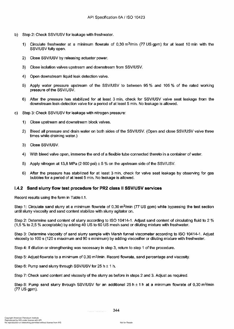
Copyright American Petroleum Institute
Reproduced by IHS under license with API
Not for ResaleNo reproduction or networking permitted without license from IHS
--`,,`,`,-`-`,,`,,`,`,,`---
API Specification 6A / ISO 10423
b) Step 2: Check SSV/USV for leakage with freshwater.
1) Circulate freshwater at a minimum flowrate of 0,30 m3/min (77 US gpm) for at least 10 min with theSSV/USV fully open.
2) Close SSV/USV by releasing actuator power.
3) Close isolation valves upstream and downstream from SSV/USV.
4) Open downstream liquid leak detection valve.
5) Apply water pressure upstream of the SSV/USV to between 95 % and 105 % of the rated workingpressure of the SSV/USV.
6) After the pressure has stabilized for at least 3 min, check for SSV/USV valve seat leakage from thedownstream leak-detection valve for a period of at least 5 min. No leakage is allowed.
c) Step 3: Check SSV/USV for leakage with nitrogen pressure:
1) Close upstream and downstream block valves.
2) Bleed all pressure and drain water on both sides of the SSV/USV. (Open and close SSV/USV valve threetimes while draining water.)
3) Close SSV/USV.
4) With bleed valve open, immerse the end of a flexible tube connected thereto in a container of water.
5) Apply nitrogen at 13,8 MPa (2 000 psi) ± 5 % on the upstream side of the SSV/USV.
6) After the pressure has stabilized for at least 3 min, check for valve seat leakage by observing for gasbubbles for a period of at least 5 min. No leakage is allowed.
1.4.2 Sand slurry flow test procedure for PR2 class II SSVlUSV services
Record results using the form in Table 1.1.
Step 1: Circulate sand slurry at a minimum flowrate of 0,30 m3/min (77 US gpm) while bypassing the test sectionuntil slurry viscosity and sand content stabilize with slurry agitator on.
Step 2: Determine sand content of slurry according to ISO 10414-1. Adjust sand content of circulating fluid to 2 %(1,5 % to 2,5 % acceptable) by adding 40 US to 60 US mesh sand or diluting mixture with freshwater.
Step 3: Determine viscosity of sand slurry sample with Marsh funnel viscometer according to ISO 10414-1. Adjustviscosity to 100 s (120 s maximum and 90 s minimum) by adding viscosifier or diluting mixture with freshwater.
Step 4: If dilution or strengthening was necessary in step 3, return to step 1 of the procedure.
Step 5: Adjust flowrate to a minimum of 0,30 m3/min. Record flowrate, sand percentage and viscosity.
Step 6: Pump sand slurry through SSV/USV for 25 h ± 1 h.
Step 7: Check sand content and viscosity of the slurry as before in steps 2 and 3. Adjust as required.
Step 8: Pump sand slurry through SSV/USV for an additional 25 h ± 1 h at a minimum flowrate of 0,30 m3/min(77 US gpm).
344
API Specification 6A / ISO 10423
b) Step 2: Check SSV/USV for leakage with freshwater.
1) Circulate freshwater at a minimum flowrate of 0,30 m3/min (77 US gpm) for at least 10 min with the SSV/USV fully open.
2) Close SSV/USV by releasing actuator power.
3) Close isolation valves upstream and downstream from SSV/USV.
4) Open downstream liquid leak detection valve.
5) Apply water pressure upstream of the SSV/USV to between 95 % and 105 % of the rated working pressure of the SSV/USV.
6) After the pressure has stabilized for at least 3 min, check for SSV/USV valve seat leakage from the downstream leak-detection valve for a period of at least 5 min. No leakage is allowed.
c) Step 3: Check SSV/USV for leakage with nitrogen pressure:
1) Close upstream and downstream block valves.
2) Bleed all pressure and drain water on both sides of the SSV/USV. (Open and close SSV/USV valve three times while draining water.)
3) Close SSV/USV.
4) With bleed valve open, immerse the end of a flexible tube connected thereto in a container of water.
5) Apply nitrogen at 13,8 MPa (2 000 psi) ± 5 % on the upstream side of the SSV/USV.
6) After the pressure has stabilized for at least 3 min, check for valve seat leakage by observing for gas bubbles for a period of at least 5 min. No leakage is allowed.
1.4.2 Sand slurry flow test procedure for PR2 class II SSVlUSV services
Record results using the form in Table 1.1.
Step 1: Circulate sand slurry at a minimum flowrate of 0,30 m3/min (77 US gpm) while bypassing the test section until slurry viscosity and sand content stabilize with slurry agitator on.
Step 2: Determine sand content of slurry according to ISO 10414-1. Adjust sand content of circulating fluid to 2 % (1,5 % to 2,5 % acceptable) by adding 40 US to 60 US mesh sand or diluting mixture with freshwater.
Step 3: Determine viscosity of sand slurry sample with Marsh funnel viscometer according to ISO 10414-1. Adjust viscosity to 100 s (120 s maximum and 90 s minimum) by adding viscosifier or diluting mixture with freshwater.
Step 4: If dilution or strengthening was necessary in step 3, return to step 1 of the procedure.
Step 5: Adjust flowrate to a minimum of 0,30 m3/min. Record flowrate, sand percentage and viscosity.
Step 6: Pump sand slurry through SSV/USV for 25 h ± 1 h.
Step 7: Check sand content and viscosity of the slurry as before in steps 2 and 3. Adjust as required.
Step 8: Pump sand slurry through SSV/USV for an additional 25 h ± 1 h at a minimum flowrate of 0,30 m3/min (77 US gpm).
344
Copyright American Petroleum Institute
Reproduced by IHS under license with API
Not for ResaleNo reproduction or networking permitted without license from IHS
--`,,`,`,-`-`,,`,,`,`,,`---
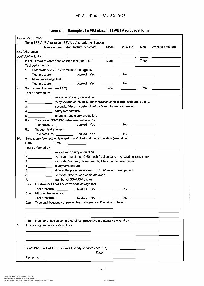
d .
Copyright American Petroleum Institute
Reproduced by IHS under license with API
Not for ResaleNo reproduction or networking permitted without license from IHS
--`,,`,`,-`-`,,`,,`,`,,`---
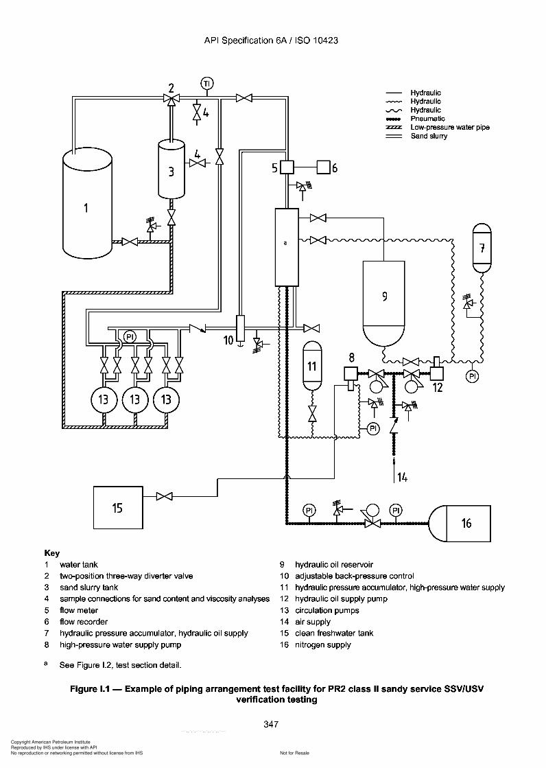
Copyright American Petroleum Institute
Reproduced by IHS under license with API
Not for ResaleNo reproduction or networking permitted without license from IHS
--`,,`,`,-`-`,,`,,`,`,,`---
API Specification 6A / ISO 10423
1
5
HydraulicHydraulic
..rv" Hydraulic- Pneumatic:zzzz Low-pressure water pipe
Sand slurry
6
9
10
1516
Key1 water tank2 two-position three-way diverter valve3 sand slurry tank4 sample connections for sand content and viscosity analyses5 flow meter6 flow recorder7 hydraulic pressure accumulator, hydraulic oil supply8 high-pressure water supply pump
9 hydraulic oil reservoir10 adjustable back-pressure control11 hydraulic pressure accumulator, high-pressure water supply12 hydraulic oil supply pump13 circulation pumps14 air supply15 clean freshwater tank16 nitrogen supply
a See Figure 1.2, test section detail.
Figure 1.1 - Example of piping arrangement test facility for PR2 class II sandy service SSVlUSVverification testing
347
API Specification 6A / ISO 10423
1
15
Key 1 water tank 2 two-position three-way diverter valve 3 sand slurry tank
10
4 sample connections for sand content and viscosity analyses 5 flow meter 6 flow recorder 7 hydraulic pressure accumulator, hydraulic oil supply 8 high-pressure water supply pump
a See Figure 1.2, test section detail.
5 6
9 hydraulic oil reservoir
Hydraulic Hydraulic
..rv" Hydraulic - Pneumatic :zzzz Low-pressure water pipe
Sand slurry
16
10 adjustable back-pressure control 11 hydraulic pressure accumulator, high-pressure water supply 12 hydraulic oil supply pump 13 circulation pumps 14 air supply 15 clean freshwater tank 16 nitrogen supply
Figure 1.1 - Example of piping arrangement test facility for PR2 class II sandy service SSVlUSV verification testing
347
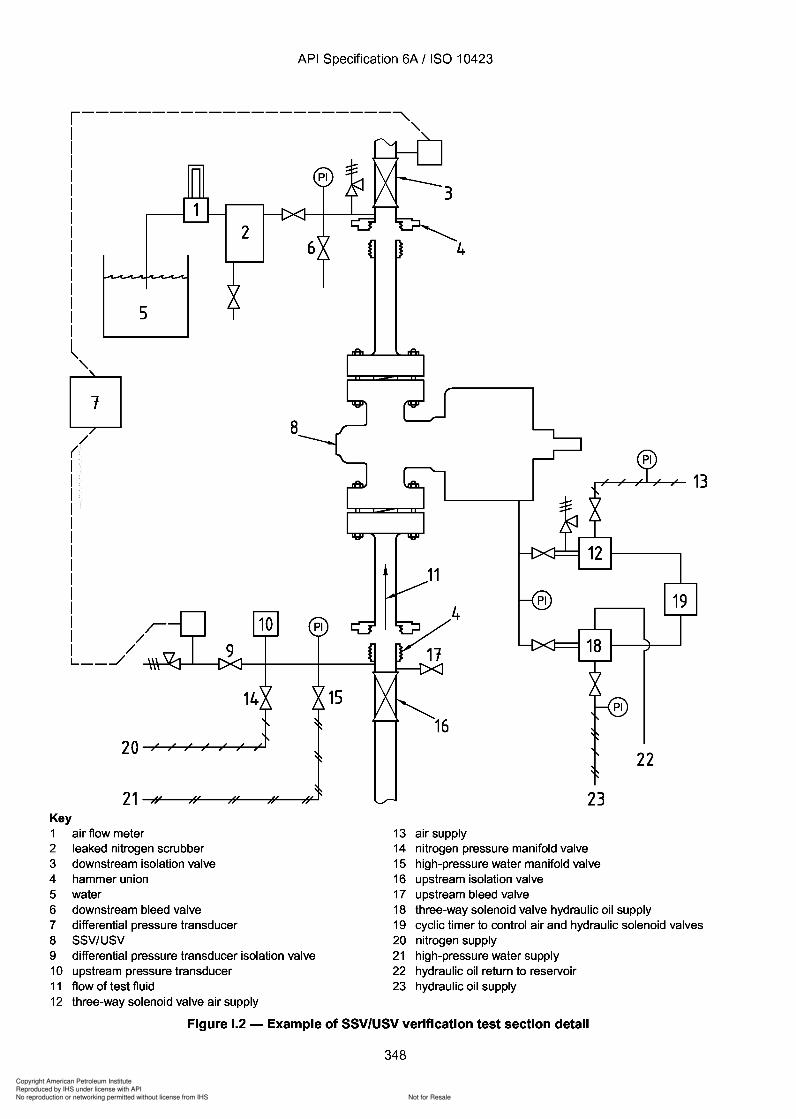
Copyright American Petroleum Institute
Reproduced by IHS under license with API
Not for ResaleNo reproduction or networking permitted without license from IHS
--`,,`,`,-`-`,,`,,`,`,,`---
Copyright American Petroleum Institute
Reproduced by IHS under license with API
Not for ResaleNo reproduction or networking permitted without license from IHS
--`,,`,`,-`-`,,`,,`,`,,`---
API Specification 6A / ISO 10423
AnnexJ
Note to users of API Specification 6A:
In this US National Adoption of ISO 10423, Annex J is withdrawn. This includes original pages 349361. However, page numbers for the remaining annexes are still consistent with those in ISO10423.
All references in the body of this specification to Annex J are also withdrawn and should be ignored.
As there are no requirements for repair or remanufacture, no API Specification 6A productcan be marked as such.
349 to 361
API Specification 6A / ISO 10423
AnnexJ
Note to users of API Specification 6A:
In this US National Adoption of ISO 10423, Annex J is withdrawn. This includes original pages 349-361. However, page numbers for the remaining annexes are still consistent with those in ISO 10423.
All references in the body of this specification to Annex J are also withdrawn and should be ignored.
As there are no requirements for repair or remanufacture, no API Specification 6A product can be marked as such.
349 to 361
Copyright American Petroleum Institute
Reproduced by IHS under license with API
Not for ResaleNo reproduction or networking permitted without license from IHS
--`,,`,`,-`-`,,`,,`,`,,`---
API Specification 6A / ISO 10423
Annex K(informative)
Recommended specifications for top connectors for christmas trees
K.1 General
This annex recommends dimensions and material strengths for top connectors, also known as christmas tree caps,for the most common sizes and pressure ratings. The dimensions and material specifications indicated allow forcompliance with all other requirements for top connectors as specified in this International Standard. If this annex isapplied, the following requirements shall be met.
K.2 Materials
Materials shall meet the requirements of 5.2 and have a minimum yield strength of 517 MPa (75000 psi) and amaximum hardness of 237 HBW in order to be suitable for H2S service. The appropriate material selection shall bemade in accordance with Table 3.
K.3 Design
The top connectors are designed for use in combinations of nominal size ranges and rated working pressure asshown in Tables K.1 and K.2 and Figure K.1.
Provisions on the collar other than indicated in Figure K.1 (and Figure K.2) for transfer of make-up torque may beprovided but are not specified in this International Standard.
K.4 Top connector dimensions
The threads shall conform to ASME B1.5 ACME screw threads as specified in Table K.1.
Dimensions for top connectors shall conform to Table K.1, Table K.2 and Table K.3 and for the flanges to theappropriate tables and requirements of 10.1 or hubs according to ISO 13533.
The maximum bore for top connectors listed in Table K.2 will typically not be large enough to pass a drift asspecified in Table 18, and will not necessarily pass a back-pressure valve.
K.5 Seal dimensions
The dimensions and materials of the "0" ring seals of the caps are specified in Table K.5, Table K.6 and Table K.7and shall conform to SAE AS 568 A.
K.6 Bleeder connection dimensions
The dimensions of the bleeder connection shall conform to 4.4.4 or 10.11 depending on the pressure rating of thetop connector.
362
API Specification 6A / ISO 10423
Annex K (informative)
Recommended specifications for top connectors for christmas trees
K.1 General
This annex recommends dimensions and material strengths for top connectors, also known as christmas tree caps, for the most common sizes and pressure ratings. The dimensions and material specifications indicated allow for compliance with all other requirements for top connectors as specified in this International Standard. If this annex is applied, the following requirements shall be met.
K.2 Materials
Materials shall meet the requirements of 5.2 and have a minimum yield strength of 517 MPa (75000 psi) and a maximum hardness of 237 HBW in order to be suitable for H2S service. The appropriate material selection shall be made in accordance with Table 3.
K.3 Design
The top connectors are designed for use in combinations of nominal size ranges and rated working pressure as shown in Tables K.1 and K.2 and Figure K.1.
Provisions on the collar other than indicated in Figure K.1 (and Figure K.2) for transfer of make-up torque may be provided but are not specified in this International Standard.
K.4 Top connector dimensions
The threads shall conform to ASME B1.5 ACME screw threads as specified in Table K.1.
Dimensions for top connectors shall conform to Table K.1, Table K.2 and Table K.3 and for the flanges to the appropriate tables and requirements of 10.1 or hubs according to ISO 13533.
The maximum bore for top connectors listed in Table K.2 will typically not be large enough to pass a drift as specified in Table 18, and will not necessarily pass a back-pressure valve.
K.S Seal dimensions
The dimensions and materials of the "0" ring seals of the caps are specified in Table K.5, Table K.6 and Table K.7 and shall conform to SAE AS 568 A.
K.6 Bleeder connection dimensions
The dimensions of the bleeder connection shall conform to 4.4.4 or 10.11 depending on the pressure rating of the top connector.
362
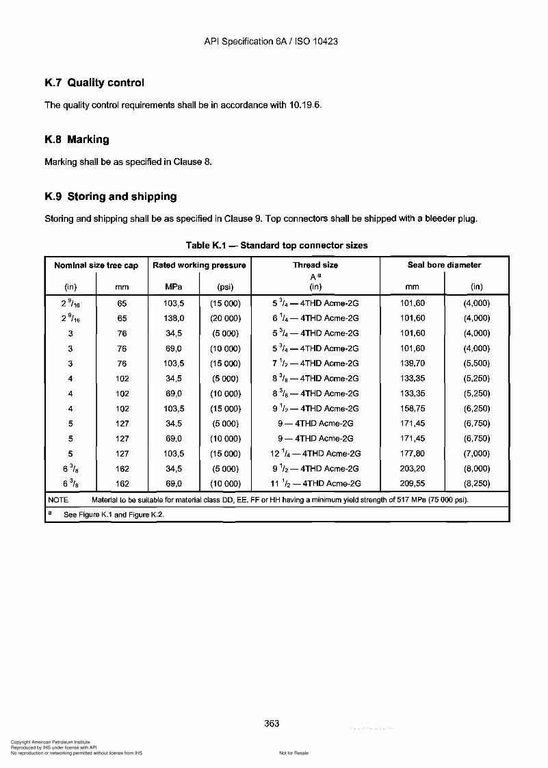
Copyright American Petroleum Institute
Reproduced by IHS under license with API
Not for ResaleNo reproduction or networking permitted without license from IHS
--`,,`,`,-`-`,,`,,`,`,,`---
API Specification 6A / ISO 10423
K.7 Quality control
The quality control requirements shall be in accordance with 10.19.6.
K.8 Marking
Marking shall be as specified in Clause 8.
K.9 Storing and shipping
Storing and shipping shall be as specified in Clause 9. Top connectors shall be shipped with a bleeder plug.
Table K.1 - Standard top connector sizes
Nominal size tree cap Rated working pressure Thread size Seal bore diameterAa
(in) mm MPa (psi) (in) mm (in)
2 9/ 16 65 103,5 (15000) 5 3
/ 4 - 4THD Acme-2G 101,60 (4,000)
2 9/ 16 65 138,0 (20000) 6 1
/ 4 - 4THD Acme-2G 101,60 (4,000)
3 76 34,5 (5000) 5 3/4 - 4THD Acme-2G 101,60 (4,000)
3 76 69,0 (10000) 5 3/ 4 - 4THD Acme-2G 101,60 (4,000)
3 76 103,5 (15000) 7 1/ 2 - 4THD Acme-2G 139,70 (5,500)
4 102 34,5 (5000) 8 % - 4THD Acme-2G 133,35 (5,250)
4 102 69,0 (10000) 8 % - 4THD Acme-2G 133,35 (5,250)
4 102 103,5 (15000) 9 1/ 2 - 4THD Acme-2G 158,75 (6,250)
5 127 34,5 (5000) 9 - 4THD Acme-2G 171,45 (6,750)
5 127 69,0 (10 000) 9 - 4THD Acme-2G 171,45 (6,750)
5 127 103,5 (15000) 12 1/4 -4THD Acme-2G 177,80 (7,000)
6% 162 34,5 (5000) 9 1/ 2 - 4THD Acme-2G 203,20 (8,000)
6% 162 69,0 (10000) 11 1/2 - 4THD Acme-2G 209,55 (8,250)
NOTE Material to be suitable for material class DO, EE, FF or HH having a minimum yield strength of 517 MPa (75 000 psi).
a See Figure K.1 and Figure K.2.
363
API Specification 6A / ISO 10423
K.7 Quality control
The quality control requirements shall be in accordance with 10.19.6.
K.B Marking
Marking shall be as specified in Clause 8.
K.9 Storing and shipping
Storing and shipping shall be as specified in Clause 9. Top connectors shall be shipped with a bleeder plug.
Table K.1 - Standard top connector sizes
Nominal size tree cap Rated working pressure Thread size Seal bore diameter Aa
(in) mm MPa (psi) (in) mm (in)
2 9/ 16 65 103,5 (15000) 5 3
/4 - 4THD Acme-2G 101,60 (4,000)
2 9/ 16 65 138,0 (20000) 6 1/4 - 4THD Acme-2G 101,60 (4,000)
3 76 34,5 (5000) 5 3/4 - 4THD Acme-2G 101,60 (4,000)
3 76 69,0 (10000) 5 3/4 - 4THD Acme-2G 101,60 (4,000)
3 76 103,5 (15000) 7 1/2 - 4THD Acme-2G 139,70 (5,500)
4 102 34,5 (5000) 8 % - 4THD Acme-2G 133,35 (5,250)
4 102 69,0 (10000) 8 % - 4THD Acme-2G 133,35 (5,250)
4 102 103,5 (15000) 9 1/2 - 4THD Acme-2G 158,75 (6,250)
5 127 34,5 (5000) 9 - 4THD Acme-2G 171,45 (6,750)
5 127 69,0 (10 000) 9 - 4THD Acme-2G 171,45 (6,750)
5 127 103,5 (15000) 121/4 -4THD Acme-2G 177,80 (7,000)
6% 162 34,5 (5000) 9 1/2 - 4THD Acme-2G 203,20 (8,000)
6% 162 69,0 (10000) 11 1/2 - 4THD Acme-2G 209,55 (8,250)
NOTE Material to be suitable for material class DO, EE, FF or HH having a minimum yield strength of 517 MPa (75 000 psi).
a See Figure K.1 and Figure K.2.
363
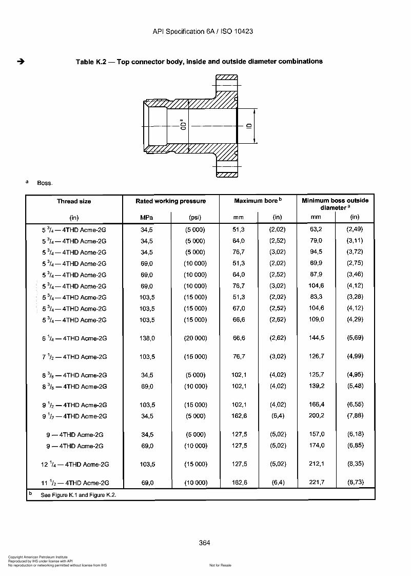
Copyright American Petroleum Institute
Reproduced by IHS under license with API
Not for ResaleNo reproduction or networking permitted without license from IHS
--`,,`,`,-`-`,,`,,`,`,,`---
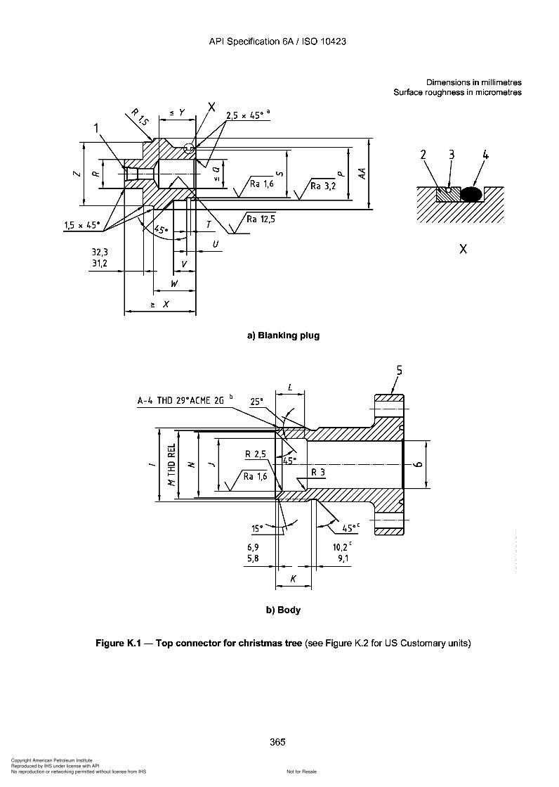
4
Copyright American Petroleum Institute
Reproduced by IHS under license with API
Not for ResaleNo reproduction or networking permitted without license from IHS
--`,,`,`,-`-`,,`,,`,`,,`---
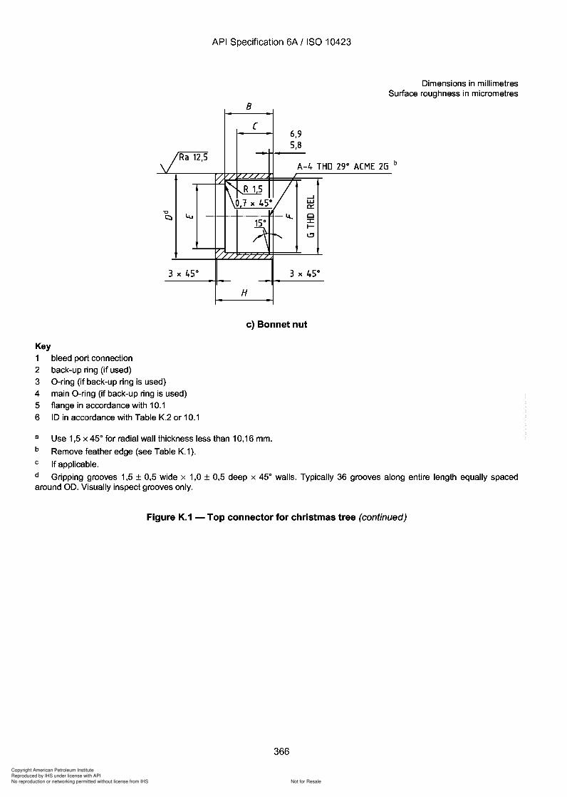
Copyright American Petroleum Institute
Reproduced by IHS under license with API
Not for ResaleNo reproduction or networking permitted without license from IHS
--`,,`,`,-`-`,,`,,`,`,,`---
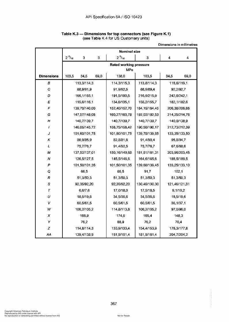
Copyright American Petroleum Institute
Reproduced by IHS under license with API
Not for ResaleNo reproduction or networking permitted without license from IHS
--`,,`,`,-`-`,,`,,`,`,,`---
API Specification 6A / ISO 10423
Table K.3 - Dimensions for top connectors (see Figure K.1)(see Table KA for US Customary units)
Dimensions in millimetres
Nominal size
2 9/ 16 3 3 I 2 9
/ 16 I 3 I 4 4
Rated working pressure
MPa
Dimensions 103,5 34,5 69,0 138,0 103,5 34,5 69,0
B 113,3/114,3 114,3/115,3 113,8/114,3 118,6/119,1
C 88,9/91,9 91,9/92,5 88,9/89,4 92,2/92,7
D 166,1/165,1 191,5/190,5 216,9/215,9 242,6/242,1
E 115,6/116,1 134,6/135,1 155,2/155,7 182,1/182,6
F 139,70/140,00 152,40/152,70 184,15/184,45 206,38/206,68
G 147,57/148,08 160,27/160,78 192,02/192,53 214,25/214,76
H 140,7/139,7 140,7/139,7 140,7/139,7 140,0/138,9
I 146,05/145,72 158,75/158,42 190,50/190,17 212,73/212,39
J 101,60/101,75 101,60/101,75 139,70/139,85 133,35/133,50
K 86,9/85,9 82,8/81,8 91,4/90,4 95,8/94,7
L 75,7/76,7 91,4/92,5 75,7/76,7 67,6/68,6
M 137,52/137,01 150,16/149,68 181,81/181,31 203,96/203,45
N 126,5/127,5 145,5/146,6 164,6/165,6 188,5/189,5
P 101,50/101,35 101,50/101,35 139,60/139,45 133,25/133,10
Q 66,5 66,5 91,7 102,1
R 51,3/50,3 51,3/50,3 51,3/50,3 51,3/50,3
S 92,35/92,20 92,35/92,20 130,45/130,30 121,46/121,31
T 6,6/7,6 17,0/18,0 17,5/18,5 9,1/10,2
U 18,5/19,6 34,5/35,6 34,5/35,6 18,5/19,6
V 60,5/61,5 60,5/61,5 60,5/61,5 36,1/37,1
W 106,2/105,2 114,8/113,8 106,2/105,2 97,0/96,0
X 166,9 174,5 165,4 148,3
Y 76,2 88,9 76,2 70,4
Z 114,8/114,3 133,9/133,4 154,4/153,9 178,3/177,8
AA 139,4/138,9 151,9/151,4 181,9/181,4 204,7/204,2
367
Dimensions
B
C
D
E
F
G
H
I
J
K
L
M
N
P
Q
R
S
T
U
V
W
X
Y
Z
AA
API Specification 6A / ISO 10423
Table K.3 - Dimensions for top connectors (see Figure K.1) (see Table K.4 for US Customary units)
Dimensions in millimetres
Nominal size
2 9/16 3 3 I 2 9
/16 I 3 I 4 4
Rated working pressure
MPa
103,5 34,5 69,0 138,0 103,5 34,5 69,0
113,3/114,3 114,3/115,3 113,8/114,3 118,6/119,1
88,9/91,9 91,9/92,5 88,9/89,4 92,2/92,7
166,1/165,1 191,5/190,5 216,9/215,9 242,6/242,1
115,6/116,1 134,6/135,1 155,2/155,7 182,1/182,6
139,70/140,00 152,40/152,70 184,15/184,45 206,38/206,68
147,57/148,08 160,27/160,78 192,02/192,53 214,25/214,76
140,71139,7 140,7/139,7 140,7/139,7 140,0/138,9
146,05/145,72 158,75/158,42 190,50/190,17 212,73/212,39
101,60/101,75 101,60/101,75 139,70/139,85 133,35/133,50
86,9/85,9 82,8/81,8 91,4/90,4 95,8/94,7
75,7/76,7 91,4/92,5 75,7176,7 67,6/68,6
137,52/137,01 150,16/149,68 181,81/181,31 203,96/203,45
126,51127,5 145,5/146,6 164,6/165,6 188,5/189,5
101,50/101,35 101,50/101,35 139,60/139,45 133,25/133,10
66,5 66,5 91,7 102,1
51,3/50,3 51,3/50,3 51,3/50,3 51,3/50,3
92,35/92,20 92,35/92,20 130,45/130,30 121,46/121,31
6,6/7,6 17,0/18,0 17,5/18,5 9,1110,2
18,5/19,6 34,5/35,6 34,5/35,6 18,5/19,6
60,5/61,5 60,5/61,5 60,5/61,5 36,1/37,1
106,2/105,2 114,8/113,8 106,2/105,2 97,0/96,0
166,9 174,5 165,4 148,3
76,2 88,9 76,2 70,4
114,8/114,3 133,9/133,4 154,41153,9 178,3/177 ,8
139,41138,9 151,9/151,4 181,9/181,4 204,7/204,2
367
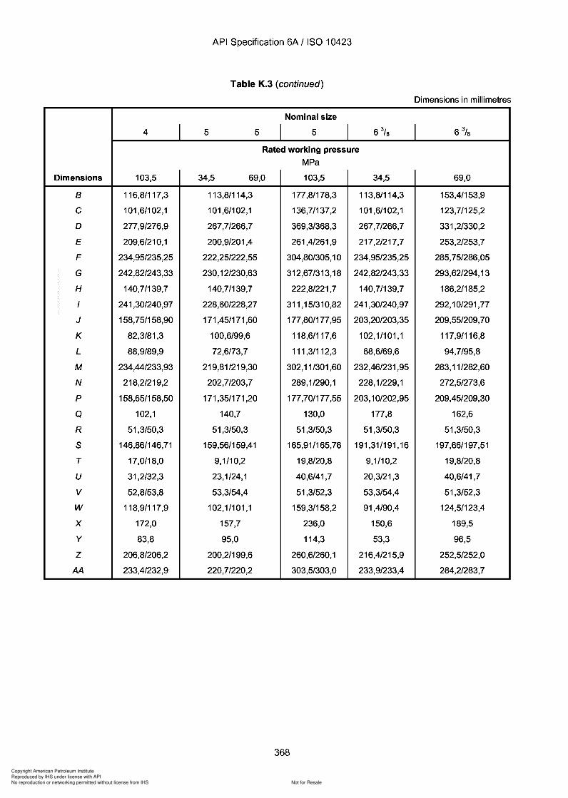
Copyright American Petroleum Institute
Reproduced by IHS under license with API
Not for ResaleNo reproduction or networking permitted without license from IHS
--`,,`,`,-`-`,,`,,`,`,,`---
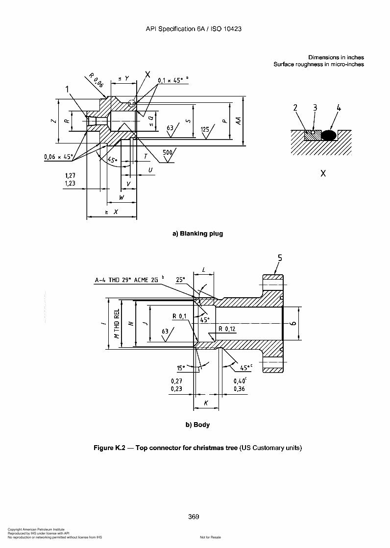
4
Copyright American Petroleum Institute
Reproduced by IHS under license with API
Not for ResaleNo reproduction or networking permitted without license from IHS
--`,,`,`,-`-`,,`,,`,`,,`---
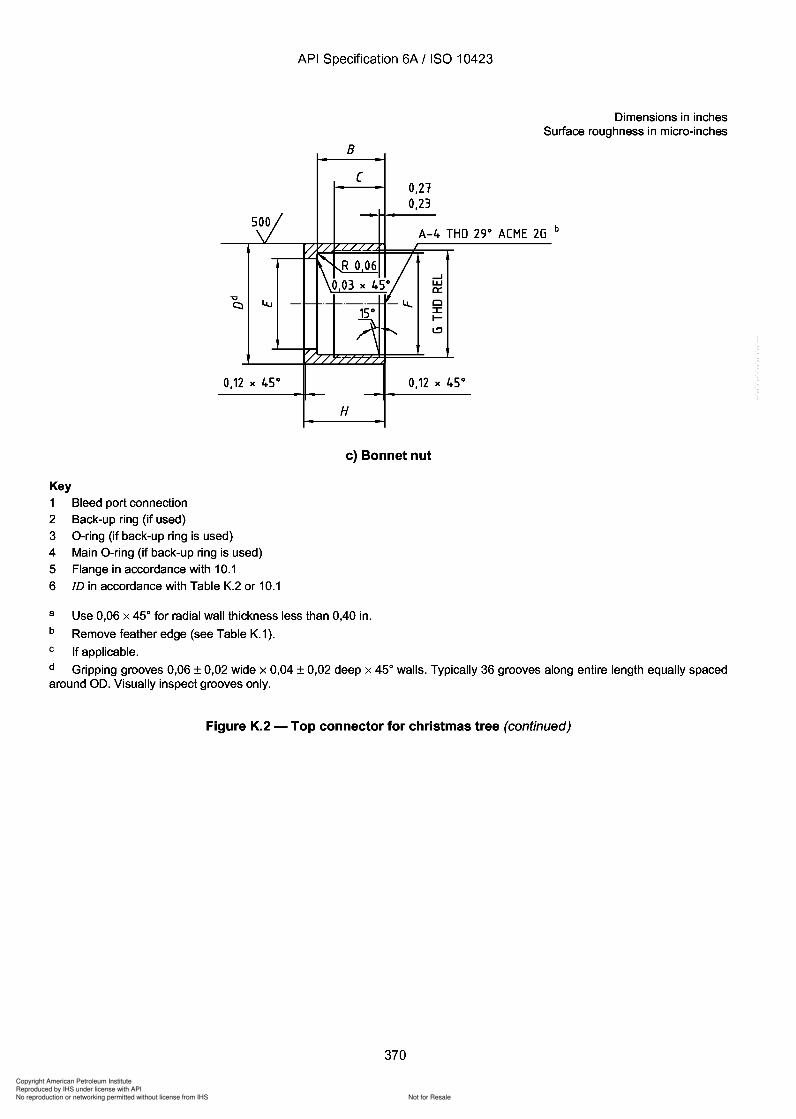
Copyright American Petroleum Institute
Reproduced by IHS under license with API
Not for ResaleNo reproduction or networking permitted without license from IHS
--`,,`,`,-`-`,,`,,`,`,,`---
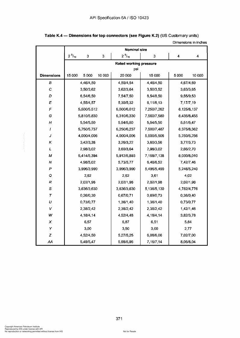
Copyright American Petroleum Institute
Reproduced by IHS under license with API
Not for ResaleNo reproduction or networking permitted without license from IHS
--`,,`,`,-`-`,,`,,`,`,,`---
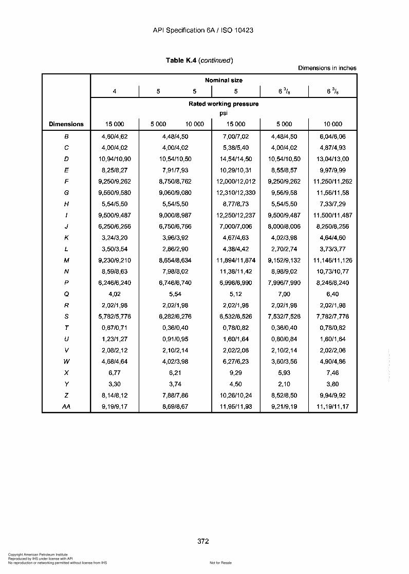
Copyright American Petroleum Institute
Reproduced by IHS under license with API
Not for ResaleNo reproduction or networking permitted without license from IHS
--`,,`,`,-`-`,,`,,`,`,,`---
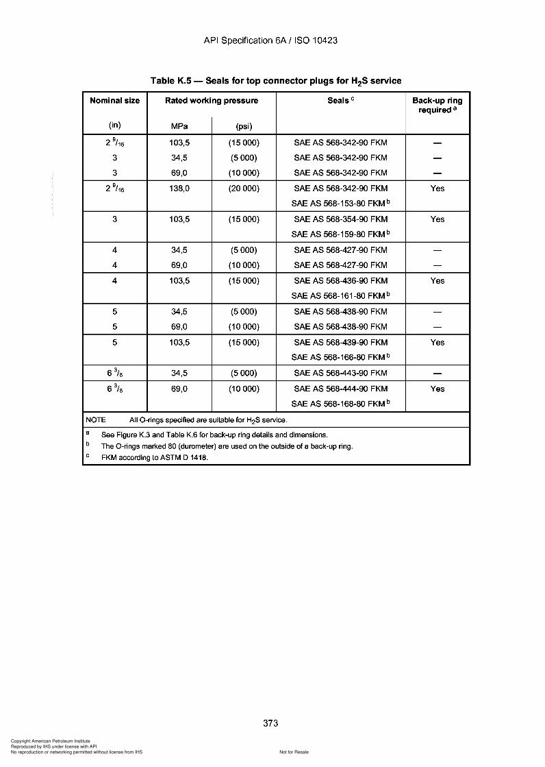
373
Copyright American Petroleum Institute
Reproduced by IHS under license with API
Not for ResaleNo reproduction or networking permitted without license from IHS
--`,,`,`,-`-`,,`,,`,`,,`---
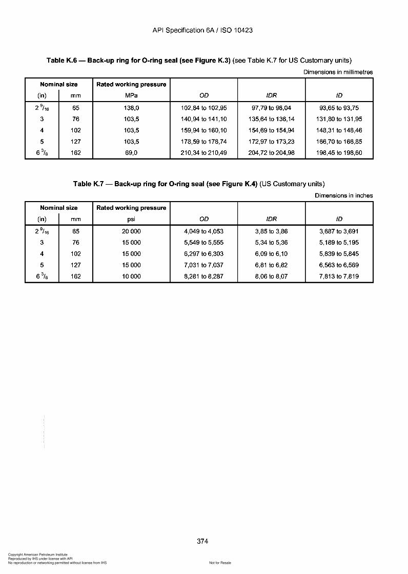
Copyright American Petroleum Institute
Reproduced by IHS under license with API
Not for ResaleNo reproduction or networking permitted without license from IHS
--`,,`,`,-`-`,,`,,`,`,,`---
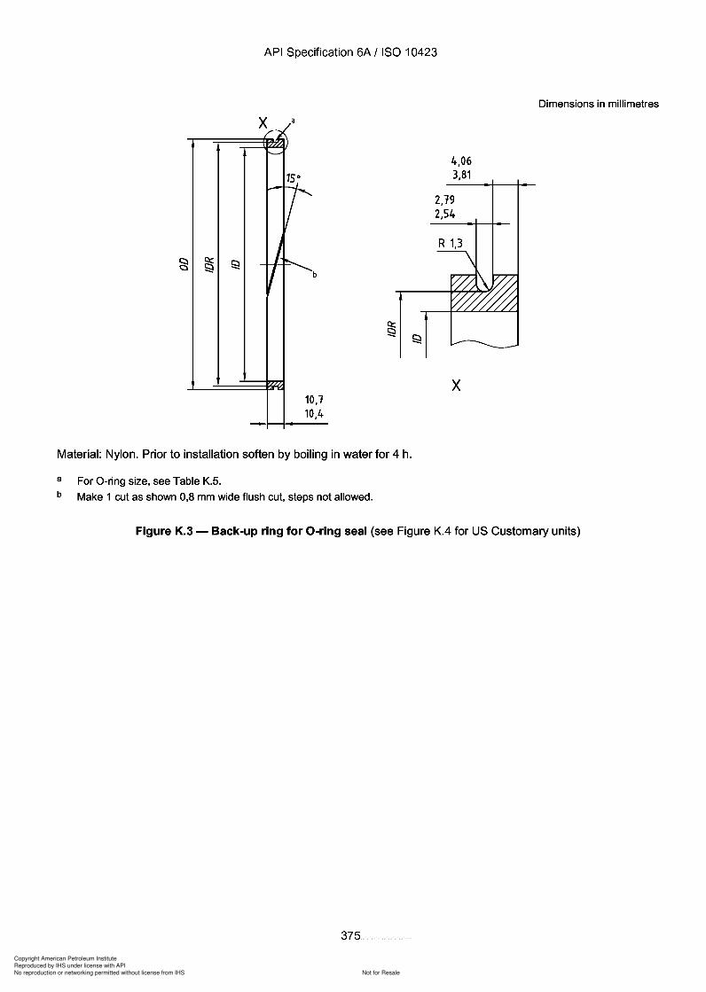
4.06
3
Copyright American Petroleum Institute
Reproduced by IHS under license with API
Not for ResaleNo reproduction or networking permitted without license from IHS
--`,,`,`,-`-`,,`,,`,`,,`---
API Specification 6A / ISO 10423
Dimensions in millimetres
x
4,063,81
R 1,3
2,192,54
x/:,/~
'----'"
-7Q::
S:! JS:! I b
-10.110,4
Material: Nylon. Prior to installation soften by boiling in water for 4 h.
a
b
For O-ring size, see Table K.S.
Make 1 cut as shown 0,8 mm wide flush cut, steps not allowed.
Figure K.3 - Back-up ring for O-ring seal (see Figure K.4 for US Customary units)
375
Q: S:! S:!
API Specification 6A / ISO 10423
~/ )
x '----'"
-7 I l
-
b
10,1 10,4
4,06 3,81
2,19 2,54
R 1,3
x
Dimensions in millimetres
Material: Nylon. Prior to installation soften by boiling in water for 4 h.
a For O-ring size, see Table K.5. b Make 1 cut as shown 0,8 mm wide flush cut, steps not allowed.
Figure K.3 - Back-up ring for O-ring seal (see Figure K.4 for US Customary units)
375
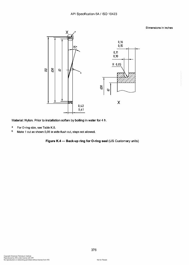
Copyright American Petroleum Institute
Reproduced by IHS under license with API
Not for ResaleNo reproduction or networking permitted without license from IHS
--`,,`,`,-`-`,,`,,`,`,,`---
Copyright American Petroleum Institute
Reproduced by IHS under license with API
Not for ResaleNo reproduction or networking permitted without license from IHS
--`,,`,`,-`-`,,`,,`,`,,`---
API Specification 6A / ISO 10423
Annex L(normative)
Specifications for valve-removal preparations and valve-removal plugs
L.1 General
This annex specifies the requirements for valve-removal preparations and valve-removal plugs.
L.2 Design
Internal pressure-relief check valves, internal threaded connections and other internal devices are permitted forvalve-removal plugs, but are not specified in this International Standard.
L.3 Dimensions
L.3.1 Valve-removal preparation dimensions for 13,8 MPa (2000 psi) through 69,0 MPa (10000 psi) workingpressures shall be in accordance with Table L.1 and Figures L.1 and L.2. Included thread taper for all sizes shall be1 in 16 on diameter (reference 1° 47' 24" with the centreline). Tolerances on angles, unless otherwise noted, shallbe ± 0° 3D'.
NOTE The sharp-vee thread is specified in API Sui SA, second edition, October 1944, Table 9. This document is out ofprint. However the contents of API Sui SA, Table 9 are still valid for designing gauges for measuring sharp-vee threads.
377
API Specification 6A / ISO 10423
Annex L (normative)
Specifications for valve-removal preparations and valve-removal plugs
L.1 General
This annex specifies the requirements for valve-removal preparations and valve-removal plugs.
L.2 Design
Internal pressure-relief check valves, internal threaded connections and other internal devices are permitted for valve-removal plugs, but are not specified in this International Standard.
L.3 Dimensions
L.3.1 Valve-removal preparation dimensions for 13,8 MPa (2000 psi) through 69,0 MPa (10000 psi) working pressures shall be in accordance with Table L.1 and Figures L.1 and L.2. Included thread taper for all sizes shall be 1 in 16 on diameter (reference 1° 47' 24" with the centreline). Tolerances on angles, unless otherwise noted, shall be ± 0° 3~'.
NOTE The sharp-vee thread is specified in API Bul SA, second edition, October 1944, Table 9. This document is out of print. However the contents of API Bul SA, Table 9 are still valid for designing gauges for measuring sharp-vee threads.
377
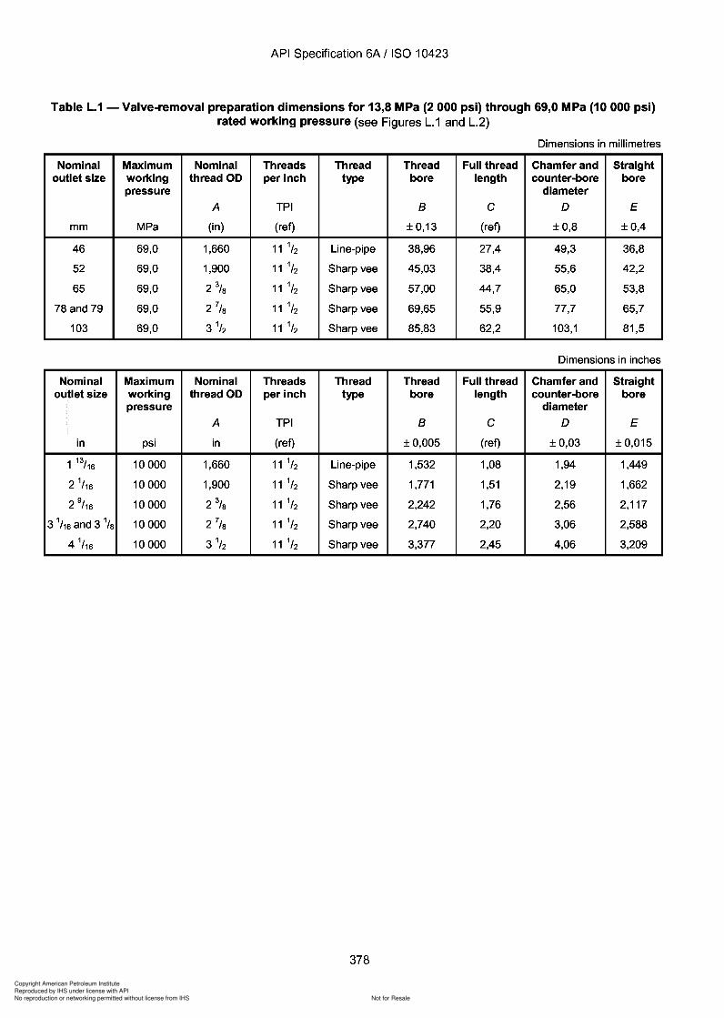
378
Copyright American Petroleum Institute
Reproduced by IHS under license with API
Not for ResaleNo reproduction or networking permitted without license from IHS
--`,,`,`,-`-`,,`,,`,`,,`---
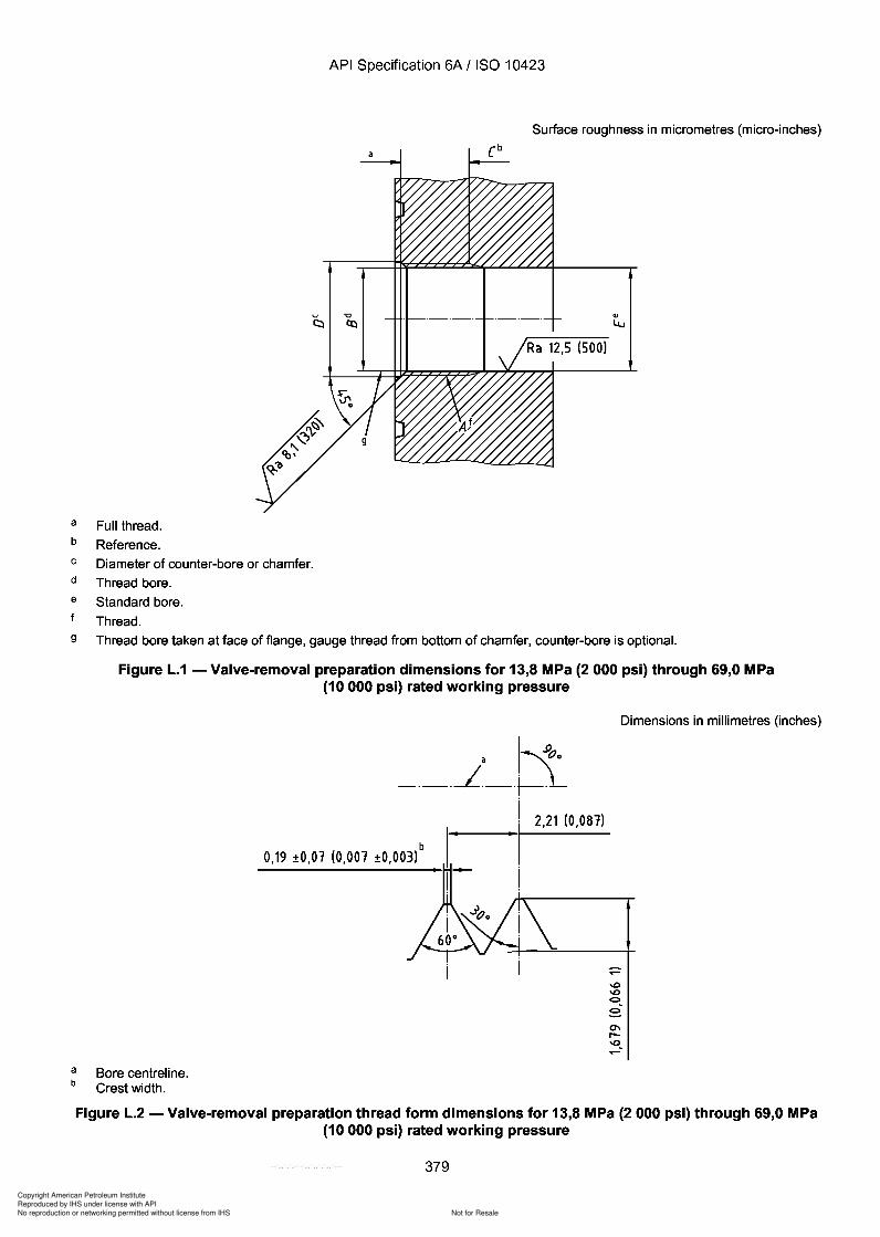
Copyright American Petroleum Institute
Reproduced by IHS under license with API
Not for ResaleNo reproduction or networking permitted without license from IHS
--`,,`,`,-`-`,,`,,`,`,,`---
API Specification 6A / ISO 10423
Surface roughness in micrometres (micro-inches)
a Full thread.
b Reference.
C Diameter of counter-bore or chamfer.
d Thread bore.
a Standard bore.
Thread.
9 Thread bore taken at face of flange, gauge thread from bottom of chamfer, counter-bore is optional.
Figure L.1 - Valve-removal preparation dimensions for 13,8 MPa (2 000 psi) through 69,0 MPa(10000 psi) rated working pressure
Dimensions in millimetres (inches)
"
a '-'.900
_._.--L._.~~
I 2,21 (0,081)
'Ib0,19 ±O,01 (0,001 ±O,003)
ab
Bore centreline.Crest width.
Figure L.2 - Valve-removal preparation thread form dimensions for 13,8 MPa (2 000 psi) through 69,0 MPa(10000 psi) rated working pressure
379
API Specification 6A / ISO 10423
Surface roughness in micrometres (micro-inches)
a Full thread.
b Reference.
C Diameter of counter-bore or chamfer.
d Thread bore.
e Standard bore.
Thread.
9 Thread bore taken at face of flange, gauge thread from bottom of chamfer, counter-bore is optional.
a b
Figure L.1 - Valve-removal preparation dimensions for 13,8 MPa (2 000 psi) through 69,0 MPa (10000 psi) rated working pressure
Bore centreline. Crest width.
a '-'.900
_._.1._.~~
b 0,19 ±O,01 (0,001 ±O,003)
I 2,21 (0,081)
'I
Dimensions in millimetres (inches)
Figure L.2 - Valve-removal preparation thread form dimensions for 13,8 MPa (2 000 psi) through 69,0 MPa (10000 psi) rated working pressure
379
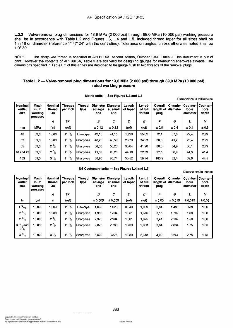
380
Copyright American Petroleum Institute
Reproduced by IHS under license with API
Not for ResaleNo reproduction or networking permitted without license from IHS
--`,,`,`,-`-`,,`,,`,`,,`---
API Specification 6A / ISO 10423
L.3.2 Valve-removal plug dimensions for 13,8 MPa (2000 psi) through 69,0 MPa (10000 psi) working pressureshall be in accordance with Table L.2 and Figures L.3, LA and L.S. Included thread taper for all sizes shall be1 in 16 on diameter (reference 1° 47' 24" with the centreline). Tolerance on angles, unless otherwise noted shall be± 0° 3D'.
NOTE The sharp-vee thread is specified in API Sui SA, second edition, October 1944, Table 9. This document is out ofprint. However the contents of API Sui SA, Table 9 are still valid for designing gauges for measuring sharp-vee threads. Thedimensions specified in Table L.2 of this annex are designed to be gauge flush to two threads of the removal plugs.
Table L.2 - Valve-removal plug dimensions for 13,8 MPa (2 000 psi) through 69,0 MPa (10 000 psi)rated working pressure
Metric units - See Figures L.3 and L.5Dimensions in millimetres
Nominal Maxi- Nominal Threads Thread Diameter Diameter Length Length Overall Chamfer Counter- Counter-outlet mum thread per inch type at large at small of taper offull length of diameter bore boresize working 00 end end thread plug diameter depth
pressure
A TPI B C 0 E F G L M
mm MPa (in) (ref) ±0,12 ±0,12 (ref) (ref) ±0,8 ±0,4 ±0,4 ±0,8
46 69,0 1,660 11 1/2 Line-pipe 42,16 41,15 16,26 25,62 72,1 37,8 22,4 26,9
52 69,0 1,900 11 1/2 Sharp vee 48,26 46,59 26,70 34,93 80,3 43,2 25,4 26,9
65 69,0 2% 11 1/2 Sharp vee 60,33 58,26 33,04 41,28 86,6 54,9 38,1 26,9
78 and 79 69,0 2 7/S 11 1/2 Sharp vee 73,03 70,26 44,18 52,39 97,5 66,9 44,5 41,4
103 69,0 3 1/2 11 1/2 Sharp vee 88,90 85,74 50,52 58,74 103,9 82,4 69,9 44,5
US Customary units - See Figures L.4 and L.5Dimensions in inches
Nominal Maxi- Nominal Threads Thread Diameter Diameter Length Length Overall Chamfer Counter- Counter-outlet mum thread per inch type at large at small of taper offull length of diameter bore boresize working 00 end end thread plug diameter depth
pressure
A TPI B C 0 E F G L M
in psi in (ref) ±0,005 ±0,005 (ref) (ref) ±0,03 ± 0,015 ± 0,015 ±0,03
1 13/16 10000 1,660 11 1/2 Line-pipe 1,660 1,620 0,640 1,009 2,84 1,488 0,88 1,06
2 1/ 16 10000 1,900 11 1/2 Sharp vee 1,900 1,834 1,051 1,375 3,16 1,702 1,00 1,06
2 9/ 16 10000 2% 11 1/2 Sharp vee 2,375 2,294 1,301 1,625 3,41 2,162 1,50 1,06
3 1/ 16 and 10000 2 7
/S 11 1/2 Sharp vee 2,875 2,766 1,739 2,063 3,84 2,634 1,75 1,633 1
/S
4 1/ 16 10000 3 1
/2 11 1/2 Sharp vee 3,500 3,376 1,989 2,313 4,09 3,244 2,75 1,75
380
API Specification 6A / ISO 10423
L.3.2 Valve-removal plug dimensions for 13,8 MPa (2000 psi) through 69,0 MPa (10000 psi) working pressure shall be in accordance with Table L.2 and Figures L.3, L.4 and L.S. Included thread taper for all sizes shall be 1 in 16 on diameter (reference 1° 47' 24" with the centreline). Tolerance on angles, unless otherwise noted shall be ± 0° 3~'.
NOTE The sharp-vee thread is specified in API Bul SA, second edition, October 1944, Table 9. This document is out of print. However the contents of API Bul SA, Table 9 are still valid for designing gauges for measuring sharp-vee threads. The dimensions specified in Table L.2 of this annex are designed to be gauge flush to two threads of the removal plugs.
Table L.2 - Valve-removal plug dimensions for 13,8 MPa (2 000 psi) through 69,0 MPa (10 000 psi) rated working pressure
Metric units - See Figures L.3 and L.5 Dimensions in millimetres
Nominal Maxi- Nominal Threads Thread Diameter Diameter Length Length Overall Chamfer Counter- Counter-outlet mum thread per inch type at large at small of taper offull length of diameter bore bore size working 00 end end thread plug diameter depth
pressure
A TPI B C 0 E F G L M
mm MPa (in) (ref) ±0,12 ±0,12 (ref) (ref) ±0,8 ±0,4 ±0,4 ±0,8
46 69,0 1,660 11 1/2 Line-pipe 42,16 41,15 16,26 25,62 72,1 37,8 22,4 26,9
52 69,0 1,900 11 1/2 Sharp vee 48,26 46,59 26,70 34,93 80,3 43,2 25,4 26,9
65 69,0 2% 11 1/2 Sharp vee 60,33 58,26 33,04 41,28 86,6 54,9 38,1 26,9
78 and 79 69,0 27/S 11 1/2 Sharp vee 73,03 70,26 44,18 52,39 97,5 66,9 44,5 41,4
103 69,0 3 1/2 11 1/2 Sharp vee 88,90 85,74 50,52 58,74 103,9 82,4 69,9 44,5
US Customary units - See Figures L.4 and L.5 Dimensions in inches
Nominal Maxi- Nominal Threads Thread Diameter Diameter Length Length Overall Chamfer Counter- Counter-outlet mum thread per inch type at large at small of taper offull length of diameter bore bore size working 00 end end thread plug diameter depth
pressure
A TPI B C 0 E F G L M
in psi in (ref) ±0,005 ±0,005 (ref) (ref) ±0,03 ± 0,015 ± 0,015 ±0,03
1 13/16 10000 1,660 11 1/2 Line-pipe 1,660 1,620 0,640 1,009 2,84 1,488 0,88 1,06
2 1/ 16 10000 1,900 11 1/2 Sharp vee 1,900 1,834 1,051 1,375 3,16 1,702 1,00 1,06
2 9/ 16 10000 2% 11 1/2 Sharp vee 2,375 2,294 1,301 1,625 3,41 2,162 1,50 1,06
3 1/ 16 and 10000 27/S 11 1/2 Sharp vee 2,875 2,766 1,739 2,063 3,84 2,634 1,75 1,63 3 1
/S
4 1/ 16 10000 3 1
/2 11 1/2 Sharp vee 3,500 3,376 1,989 2,313 4,09 3,244 2,75 1,75
380
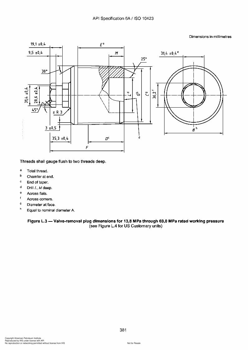
Copyright American Petroleum Institute
Reproduced by IHS under license with API
Not for ResaleNo reproduction or networking permitted without license from IHS
--`,,`,`,-`-`,,`,,`,`,,`---
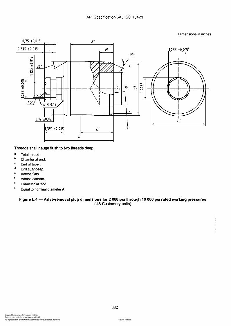
Copyright American Petroleum Institute
Reproduced by IHS under license with API
Not for ResaleNo reproduction or networking permitted without license from IHS
--`,,`,`,-`-`,,`,,`,`,,`---
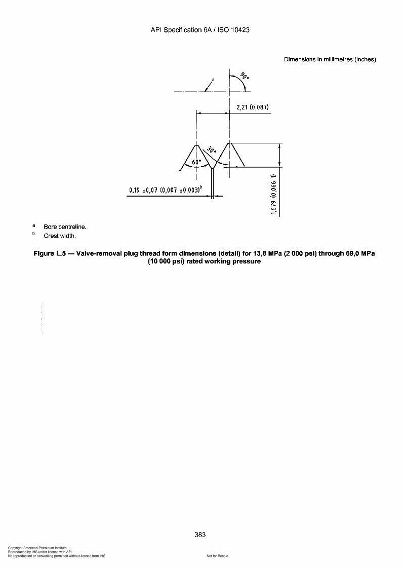
x
383
Copyright American Petroleum Institute
Reproduced by IHS under license with API
Not for ResaleNo reproduction or networking permitted without license from IHS
--`,,`,`,-`-`,,`,,`,`,,`---
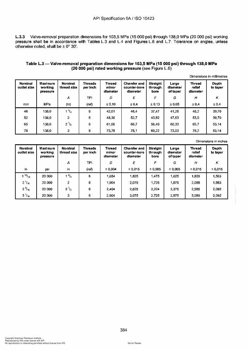
Copyright American Petroleum Institute
Reproduced by IHS under license with API
Not for ResaleNo reproduction or networking permitted without license from IHS
--`,,`,`,-`-`,,`,,`,`,,`---
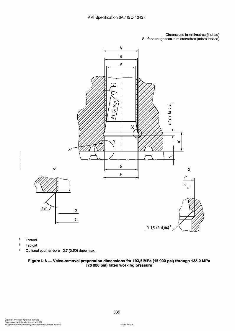
Copyright American Petroleum Institute
Reproduced by IHS under license with API
Not for ResaleNo reproduction or networking permitted without license from IHS
--`,,`,`,-`-`,,`,,`,`,,`---
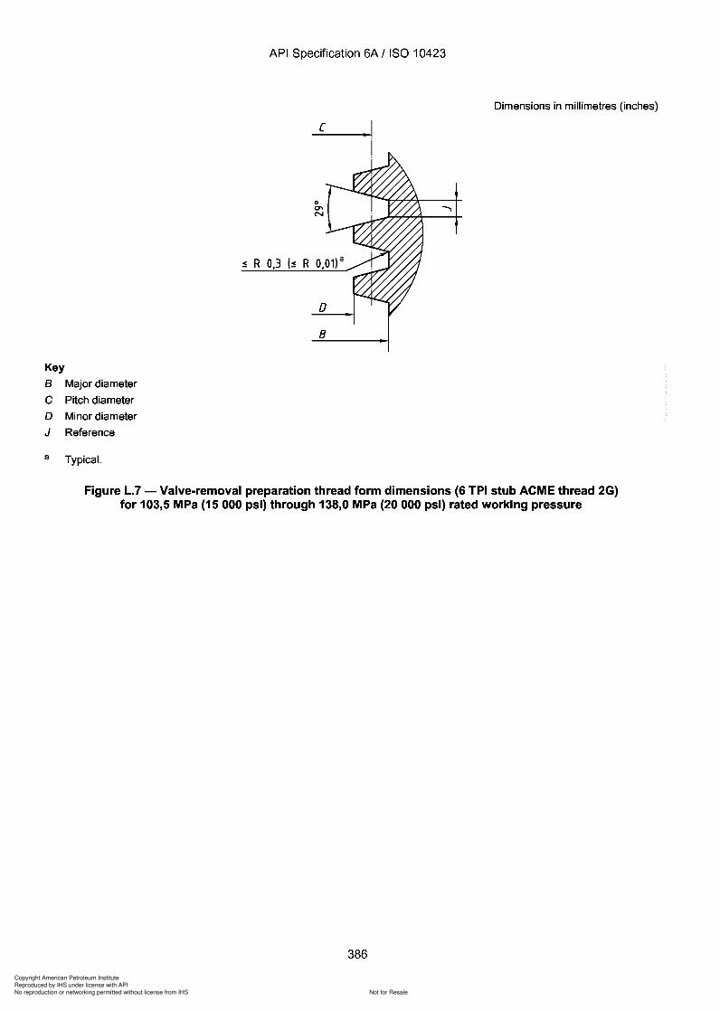
Copyright American Petroleum Institute
Reproduced by IHS under license with API
Not for ResaleNo reproduction or networking permitted without license from IHS
--`,,`,`,-`-`,,`,,`,`,,`---
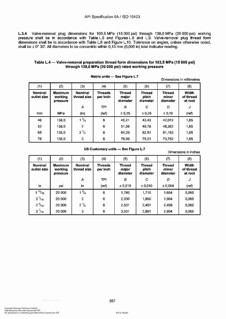
387
Copyright American Petroleum Institute
Reproduced by IHS under license with API
Not for ResaleNo reproduction or networking permitted without license from IHS
--`,,`,`,-`-`,,`,,`,`,,`---
API Specification 6A / ISO 10423
L.3.4 Valve-removal plug dimensions for 103,5 MPa (15000 psi) through 138,0 MPa (20000 psi) workingpressure shall be in accordance with Table L.5 and Figures L.8 and L.g. Valve-removal plug thread formdimensions shall be in accordance with Table L.6 and Figure L.1 O. Tolerance on angles, unless otherwise noted,shall be ± 0° 3D'. All diameters to be concentric within 0,13 mm (0,005 in) total indicator reading.
Table L.4 - Valve-removal preparation thread form dimensions for 103,5 MPa (15 000 psi)through 138,0 MPa (20000 psi) rated working pressure
Metric units - See Figure L.7Dimensions in millimetres
(1 ) (2) (3) (4) (5) (6) (7) (8)
Nominal Maximum Nominal Threads Thread Thread Thread Widthoutlet size working thread size per inch major pitch minor of thread
pressure diameter diameter diameter at root
A TPI B C D J
mm MPa (in) (ref) ±0,25 ±0,25 ±0,10 (ref)
46 138,0 1 3/4 6 45,21 43,43 42,012 1,65
52 138,0 2 6 51,56 49,78 48,362 1,65
65 138,0 2 1/2 6 64,29 62,51 61,163 1,65
78 138,0 3 6 76,99 75,21 73,762 1,65
US Customary units - See Figure L.7Dimensions in inches
(1 ) (2) (3) (4) (5) (6) (7) (8)
Nominal Maximum Nominal Threads Thread Thread Thread Widthoutlet size working thread size per inch major pitch minor of thread
pressure diameter diameter diameter at root
A TPI B C D J
in psi in (ref) ± 0,010 ± 0,010 ±0,004 (ref)
1 13/16 20000 1 3/4 6 1,780 1,710 1,654 0,065
2 1/16 20000 2 6 2,030 1,960 1,904 0,065
2 9/ 16 20000 2 1
/2 6 2,531 2,461 2,408 0,065
3 1/16 20000 3 6 3,031 2,961 2,904 0,065
387
API Specification 6A / ISO 10423
L.3.4 Valve-removal plug dimensions for 103,5 MPa (15000 psi) through 138,0 MPa (20000 psi) working pressure shall be in accordance with Table L.5 and Figures L.8 and L.g. Valve-removal plug thread form dimensions shall be in accordance with Table L.6 and Figure L.1 O. Tolerance on angles, unless otherwise noted, shall be ± 0° 3~'. All diameters to be concentric within 0,13 mm (0,005 in) total indicator reading.
Table L.4 - Valve-removal preparation thread form dimensions for 103,5 MPa (15 000 psi) through 138,0 MPa (20000 psi) rated working pressure
Metric units - See Figure L.7 Dimensions in millimetres
(1 ) (2) (3) (4) (5) (6) (7) (8)
Nominal Maximum Nominal Threads Thread Thread Thread Width outlet size working thread size per inch major pitch minor of thread
pressure diameter diameter diameter at root
A TPI B C D J
mm MPa (in) (ref) ±0,25 ±0,25 ±0,10 (ref)
46 138,0 1 3/4 6 45,21 43,43 42,012 1,65
52 138,0 2 6 51,56 49,78 48,362 1,65
65 138,0 21/2 6 64,29 62,51 61,163 1,65
78 138,0 3 6 76,99 75,21 73,762 1,65
US Customary units - See Figure L.7 Dimensions in inches
(1 ) (2) (3) (4) (5) (6) (7) (8)
Nominal Maximum Nominal Threads Thread Thread Thread Width outlet size working thread size per inch major pitch minor of thread
pressure diameter diameter diameter at root
A TPI B C D J
in psi in (ref) ± 0,010 ± 0,010 ±0,004 (ref)
1 13/16 20000 1 3/4 6 1,780 1,710 1,654 0,065
2 1/16 20000 2 6 2,030 1,960 1,904 0,065
2 9/ 16 20000 21/2 6 2,531 2,461 2,408 0,065
3 1/16 20000 3 6 3,031 2,961 2,904 0,065
387
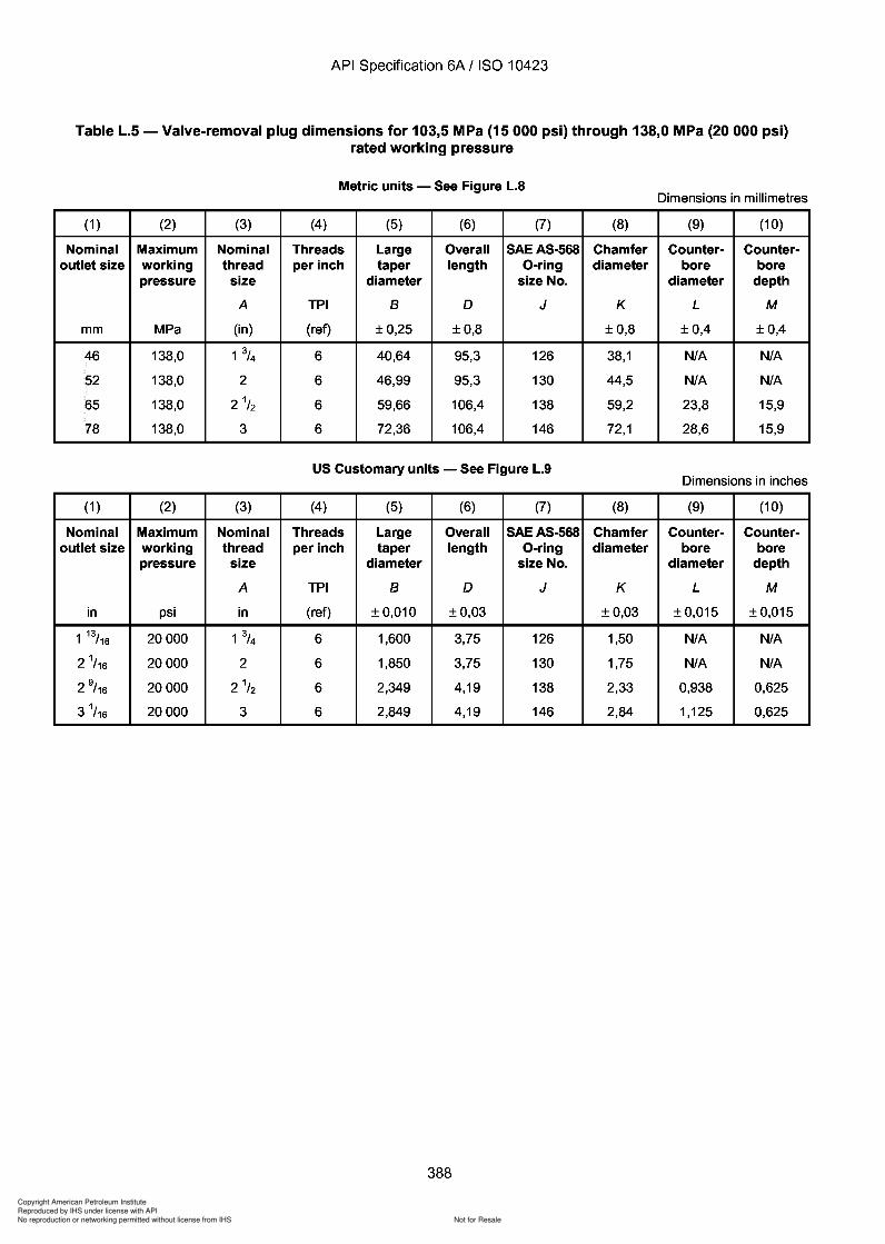
Copyright American Petroleum Institute
Reproduced by IHS under license with API
Not for ResaleNo reproduction or networking permitted without license from IHS
--`,,`,`,-`-`,,`,,`,`,,`---
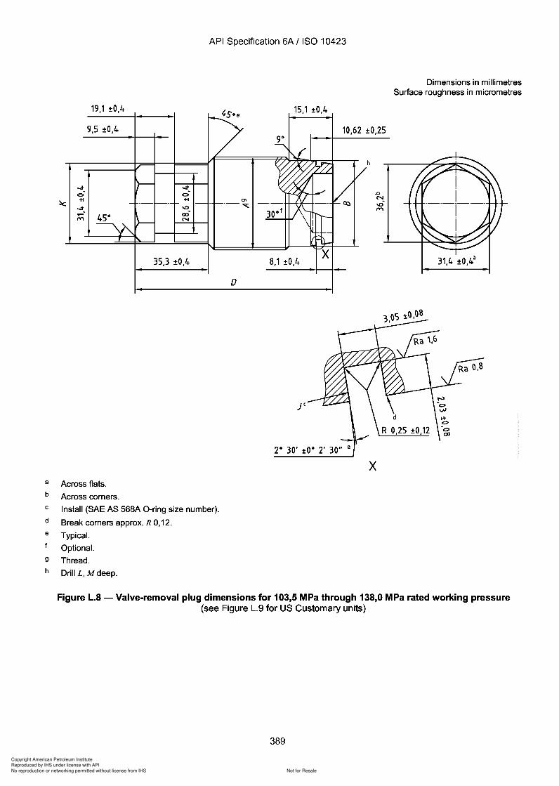
389
Copyright American Petroleum Institute
Reproduced by IHS under license with API
Not for ResaleNo reproduction or networking permitted without license from IHS
--`,,`,`,-`-`,,`,,`,`,,`---
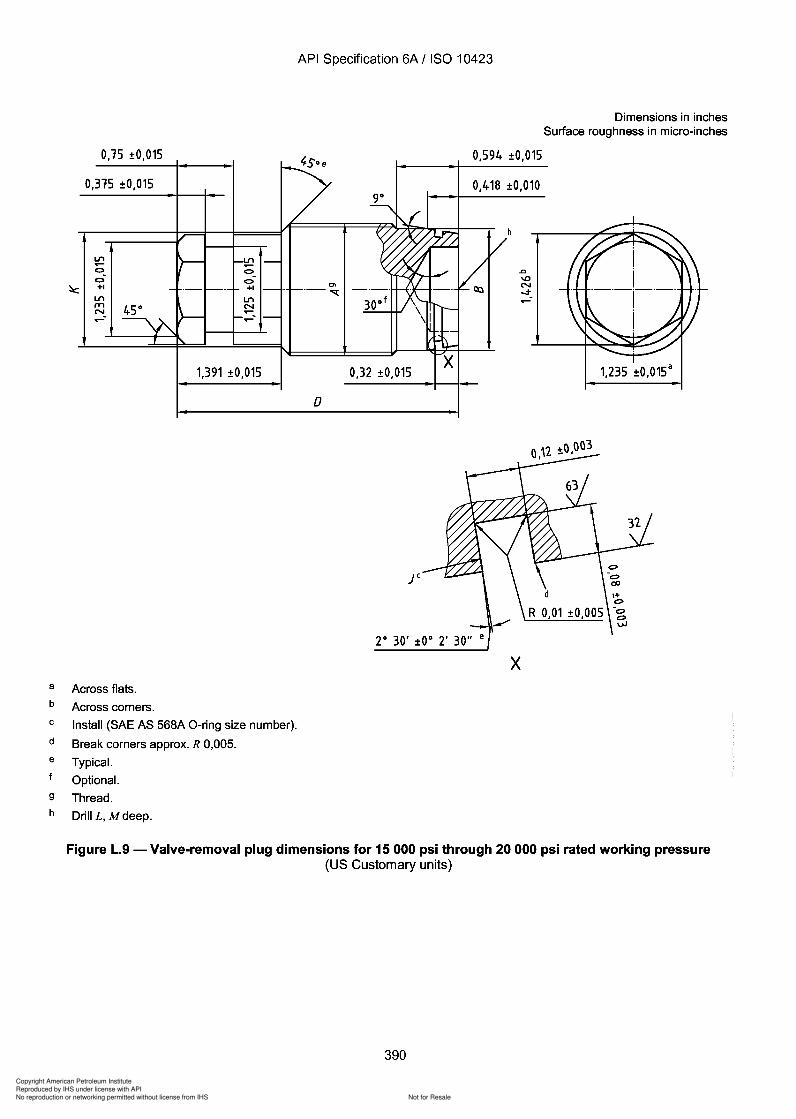
Copyright American Petroleum Institute
Reproduced by IHS under license with API
Not for ResaleNo reproduction or networking permitted without license from IHS
--`,,`,`,-`-`,,`,,`,`,,`---
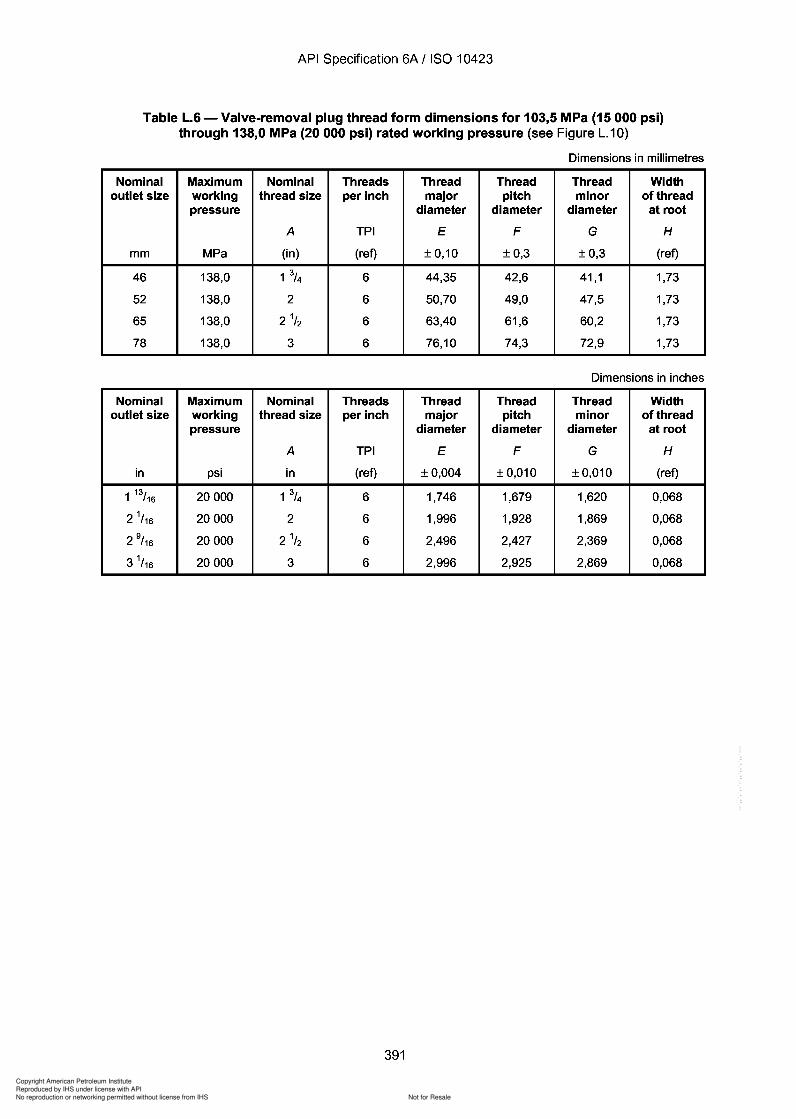
Copyright American Petroleum Institute
Reproduced by IHS under license with API
Not for ResaleNo reproduction or networking permitted without license from IHS
--`,,`,`,-`-`,,`,,`,`,,`---
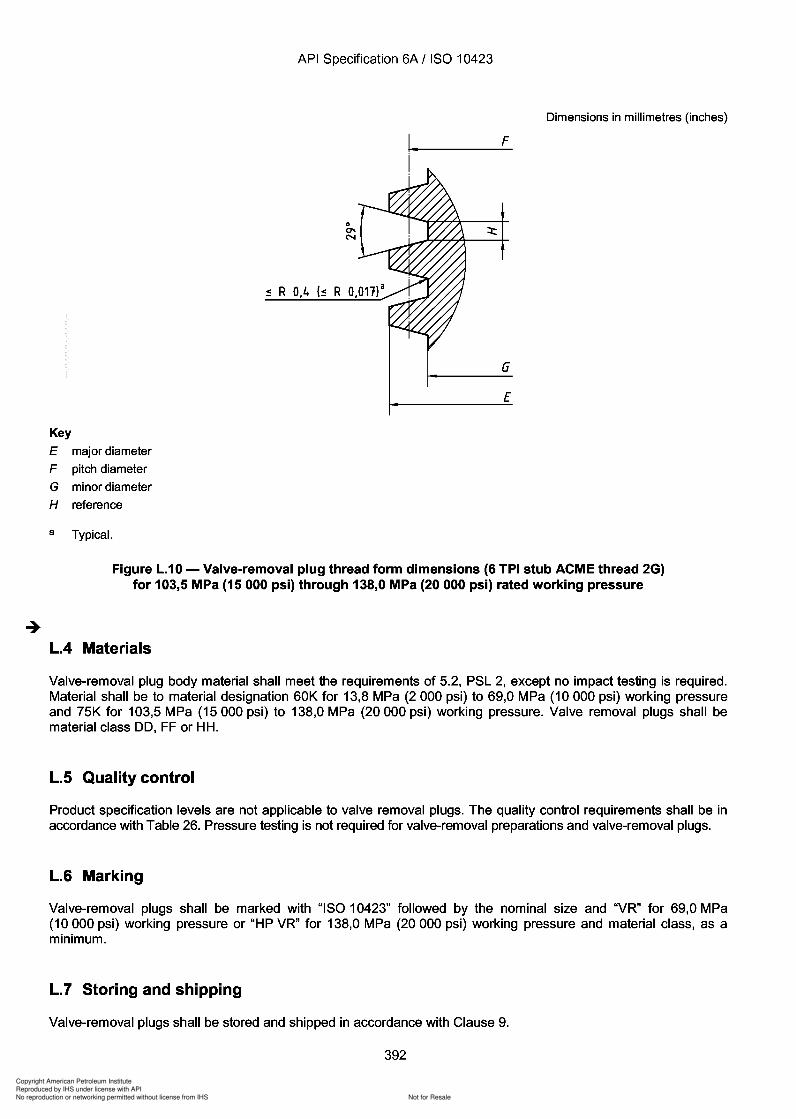
Copyright American Petroleum Institute
Reproduced by IHS under license with API
Not for ResaleNo reproduction or networking permitted without license from IHS
--`,,`,`,-`-`,,`,,`,`,,`---
393
Copyright American Petroleum Institute
Reproduced by IHS under license with API
Not for ResaleNo reproduction or networking permitted without license from IHS
--`,,`,`,-`-`,,`,,`,`,,`---
API Specification 6A / ISO 10423
Annex M(informative)
List of tables and figures
M.1 General
For those who are familiar with the API Spec 6A:1996 numbering of figures and tables, tables have been includedin this annex comparing the numbering of this International Standard and API Spec 6A:1996, seventeenth edition.A list of all figures and tables in this International Standard is also given.
393
M.1 General
API Specification 6A / ISO 10423
Annex M (informative)
List of tables and figures
For those who are familiar with the API Spec 6A:1996 numbering of figures and tables, tables have been included in this annex comparing the numbering of this International Standard and API Spec 6A:1996, seventeenth edition. A list of all figures and tables in this International Standard is also given.
393
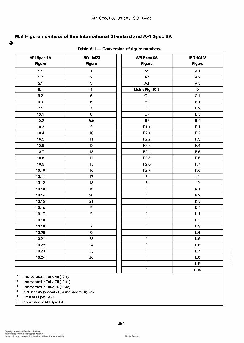
Copyright American Petroleum Institute
Reproduced by IHS under license with API
Not for ResaleNo reproduction or networking permitted without license from IHS
--`,,`,`,-`-`,,`,,`,`,,`---
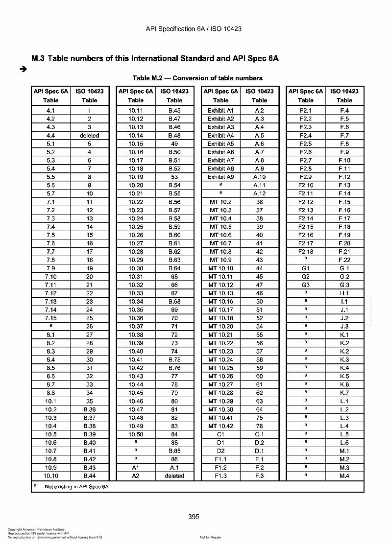
Copyright American Petroleum Institute
Reproduced by IHS under license with API
Not for ResaleNo reproduction or networking permitted without license from IHS
--`,,`,`,-`-`,,`,,`,`,,`---
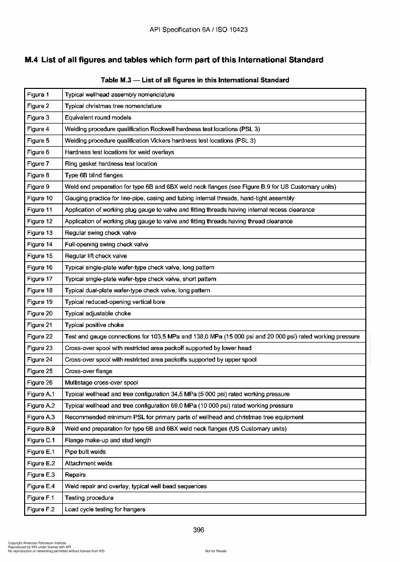
Copyright American Petroleum Institute
Reproduced by IHS under license with API
Not for ResaleNo reproduction or networking permitted without license from IHS
--`,,`,`,-`-`,,`,,`,`,,`---
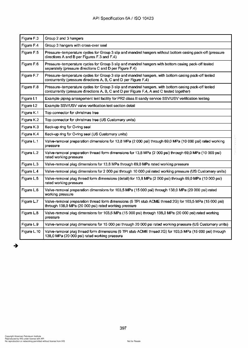
Copyright American Petroleum Institute
Reproduced by IHS under license with API
Not for ResaleNo reproduction or networking permitted without license from IHS
--`,,`,`,-`-`,,`,,`,`,,`---
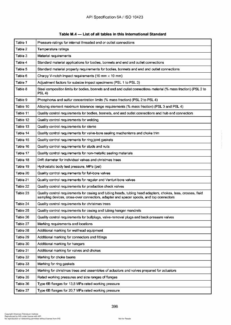
398
Copyright American Petroleum Institute
Reproduced by IHS under license with API
Not for ResaleNo reproduction or networking permitted without license from IHS
--`,,`,`,-`-`,,`,,`,`,,`---
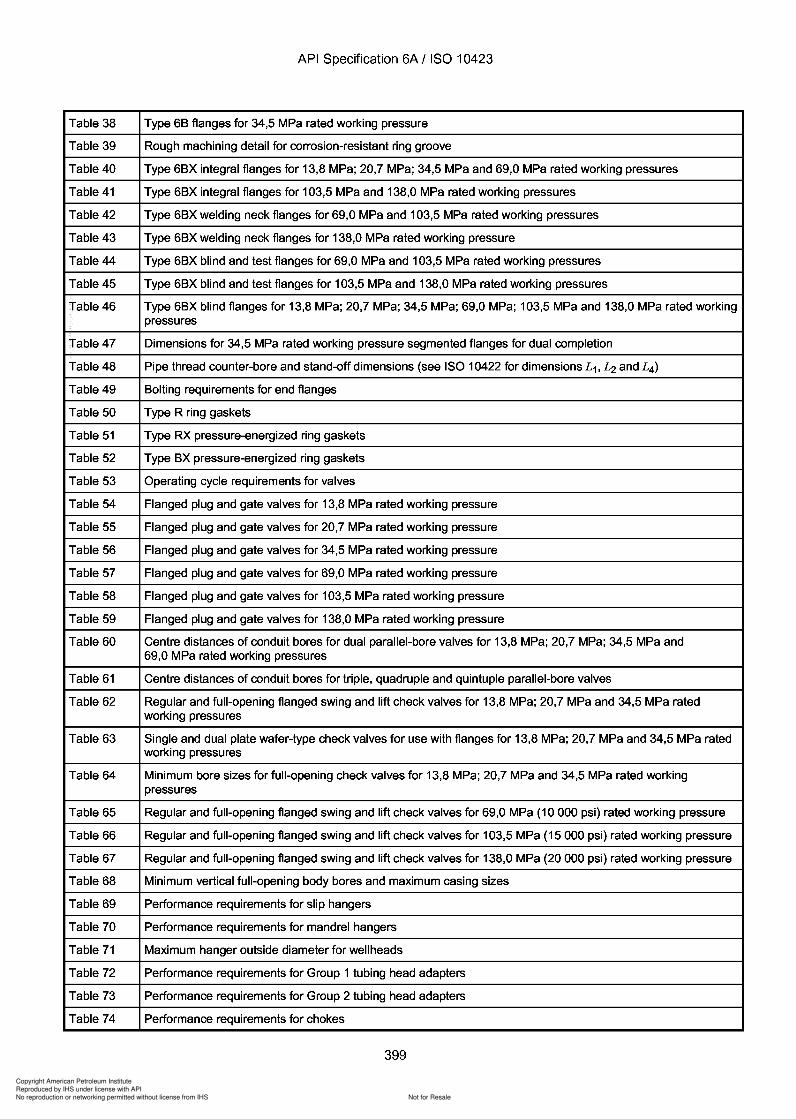
343
343
Copyright American Petroleum Institute
Reproduced by IHS under license with API
Not for ResaleNo reproduction or networking permitted without license from IHS
--`,,`,`,-`-`,,`,,`,`,,`---
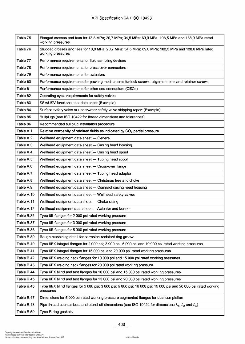
Copyright American Petroleum Institute
Reproduced by IHS under license with API
Not for ResaleNo reproduction or networking permitted without license from IHS
--`,,`,`,-`-`,,`,,`,`,,`---
API Specification 6A / ISO 10423
Table 75 Flanged crosses and tees for 13,8 MPa; 20,7 MPa; 34,5 MPa; 69,0 MPa; 103,5 MPa and 138,0 MPa ratedworking pressures
Table 76 Studded crosses and tees for 13,8 MPa; 20,7 MPa; 34,5 MPa; 69,0 MPa; 103,5 MPa and 138,0 MPa ratedworking pressures
Table 77 Performance requirements for fluid sampling devices
Table 78 Performance requirements for cross-over connectors
Table 79 Performance requirements for actuators
Table 80 Performance requirements for packing mechanisms for lock screws, alignment pins and retainer screws
Table 81 Performance requirements for other end connectors (OECs)
Table 82 Operating cycle requirements for safety valves
Table 83 SSV/USV functional test data sheet (Example)
Table 84 Surface safety valve or underwater safety valve shipping report (Example)
Table 85 Bullplugs (see ISO 10422 for thread dimensions and tolerances)
Table 86 Recommended bullplug installation procedure
TableA.1 Relative corrosivity of retained fluids as indicated by CO2 partial pressure
TableA.2 Wellhead equipment data sheet - General
TableA.3 Wellhead equipment data sheet - Casing head housing
Table A.4 Wellhead equipment data sheet - Casing head spool
TableA.5 Wellhead equipment data sheet - Tubing head spool
TableA.6 Wellhead equipment data sheet - Cross-over flange
Table A.7 Wellhead equipment data sheet - Tubing head adaptor
TableA.8 Wellhead equipment data sheet - Christmas tree and choke
TableA.9 Wellhead equipment data sheet - Compact casing head housing
TableA.10 Wellhead equipment data sheet - Wellhead safety valves
Table A.11 Wellhead equipment data sheet - Choke sizing
Table A.12 Wellhead equipment data sheet - Actuator and bonnet
Table B.36 Type 6B flanges for 2 000 psi rated working pressure
Table B.37 Type 6B flanges for 3 000 psi rated working pressure
Table B.38 Type 6B flanges for 5 000 psi rated working pressure
Table B.39 Rough machining detail for corrosion-resistant ring groove
Table B.40 Type 6BX integral flanges for 2 000 psi; 3 000 psi; 5 000 psi and 10 000 psi rated working pressures
Table B.41 Type 6BX integral flanges for 15 000 psi and 20 000 psi rated working pressures
Table B.42 Type 6BX welding neck flanges for 10 000 psi and 15 000 psi rated working pressures
Table B.43 Type 6BX welding neck flanges for 20 000 psi rated working pressure
Table B.44 Type 6BX blind and test flanges for 10 000 psi and 15 000 psi rated working pressures
Table B.45 Type 6BX blind and test flanges for 15 000 psi and 20 000 psi rated working pressures
Table B.46 Type 6BX blind flanges for 2000 psi; 3000 psi; 5000 psi; 10000 psi; 15000 psi and 20 000 psi rated workingpressures
Table B.47 Dimensions for 5 000 psi rated working pressure segmented flanges for dual completion
Table B.48 Pipe thread counter-bore and stand-off dimensions (see ISO 10422 for dimensions L 1, L2 and L 4)
Table B.50 Type R ring gaskets
400
API Specification 6A / ISO 10423
Table 75 Flanged crosses and tees for 13,8 MPa; 20,7 MPa; 34,5 MPa; 69,0 MPa; 103,5 MPa and 138,0 MPa rated working pressures
Table 76 Studded crosses and tees for 13,8 MPa; 20,7 MPa; 34,5 MPa; 69,0 MPa; 103,5 MPa and 138,0 MPa rated working pressures
Table 77 Performance requirements for fluid sampling devices
Table 78 Performance requirements for cross-over connectors
Table 79 Performance requirements for actuators
Table 80 Performance requirements for packing mechanisms for lock screws, alignment pins and retainer screws
Table 81 Performance requirements for other end connectors (OECs)
Table 82 Operating cycle requirements for safety valves
Table 83 SSV/USV functional test data sheet (Example)
Table 84 Surface safety valve or underwater safety valve shipping report (Example)
Table 85 Bullplugs (see ISO 10422 for thread dimensions and tolerances)
Table 86 Recommended bull plug installation procedure
TableA.1 Relative corrosivity of retained fluids as indicated by CO2 partial pressure
TableA.2 Wellhead equipment data sheet - General
TableA.3 Wellhead equipment data sheet - Casing head housing
Table A.4 Wellhead equipment data sheet - Casing head spool
TableA.5 Wellhead equipment data sheet - Tubing head spool
TableA.6 Wellhead equipment data sheet - Cross-over flange
Table A.7 Wellhead equipment data sheet - Tubing head adaptor
TableA.8 Wellhead equipment data sheet - Christmas tree and choke
TableA.9 Wellhead equipment data sheet - Compact casing head housing
TableA.10 Wellhead equipment data sheet - Wellhead safety valves
Table A.11 Wellhead equipment data sheet - Choke sizing
Table A.12 Wellhead equipment data sheet - Actuator and bonnet
Table B.36 Type 6B flanges for 2 000 psi rated working pressure
Table B.37 Type 6B flanges for 3 000 psi rated working pressure
Table B.38 Type 6B flanges for 5 000 psi rated working pressure
Table B.39 Rough machining detail for corrosion-resistant ring groove
Table B.40 Type 6BX integral flanges for 2 000 psi; 3 000 psi; 5 000 psi and 10 000 psi rated working pressures
Table B.41 Type 6BX integral flanges for 15 000 psi and 20 000 psi rated working pressures
Table B.42 Type 6BX welding neck flanges for 10 000 psi and 15 000 psi rated working pressures
Table B.43 Type 6BX welding neck flanges for 20 000 psi rated working pressure
Table B.44 Type 6BX blind and test flanges for 10 000 psi and 15 000 psi rated working pressures
Table B.45 Type 6BX blind and test flanges for 15 000 psi and 20 000 psi rated working pressures
Table B.46 Type 6BX blind flanges for 2000 psi; 3000 psi; 5000 psi; 10000 psi; 15000 psi and 20 000 psi rated working pressures
Table B.47 Dimensions for 5 000 psi rated working pressure segmented flanges for dual completion
Table B.48 Pipe thread counter-bore and stand-off dimensions (see ISO 10422 for dimensions L 1, L2 and L4)
Table B.50 Type R ring gaskets
400
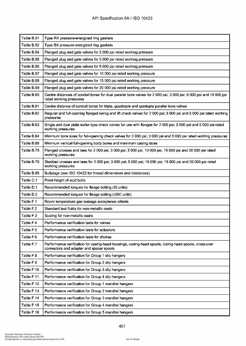
Copyright American Petroleum Institute
Reproduced by IHS under license with API
Not for ResaleNo reproduction or networking permitted without license from IHS
--`,,`,`,-`-`,,`,,`,`,,`---
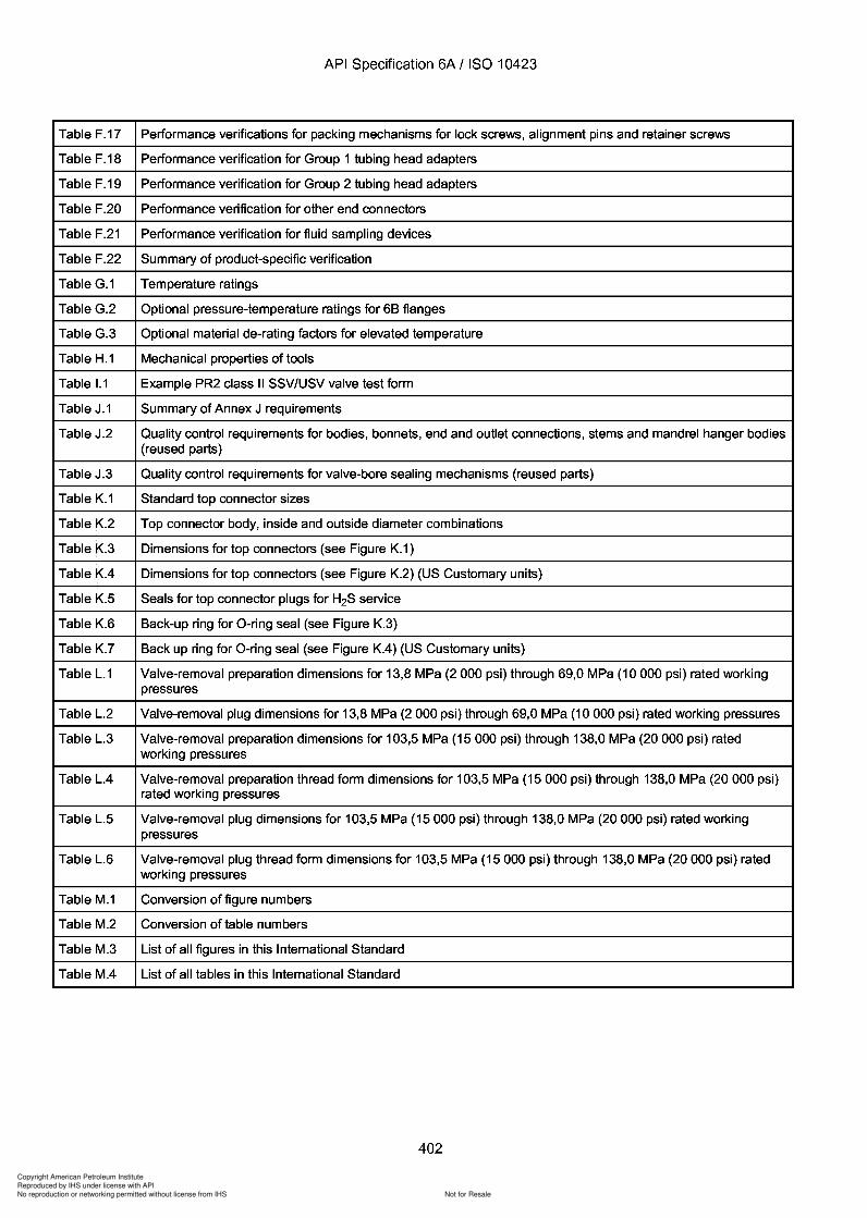
Copyright American Petroleum Institute
Reproduced by IHS under license with API
Not for ResaleNo reproduction or networking permitted without license from IHS
--`,,`,`,-`-`,,`,,`,`,,`---
.3
Copyright American Petroleum Institute
Reproduced by IHS under license with API
Not for ResaleNo reproduction or networking permitted without license from IHS
--`,,`,`,-`-`,,`,,`,`,,`---
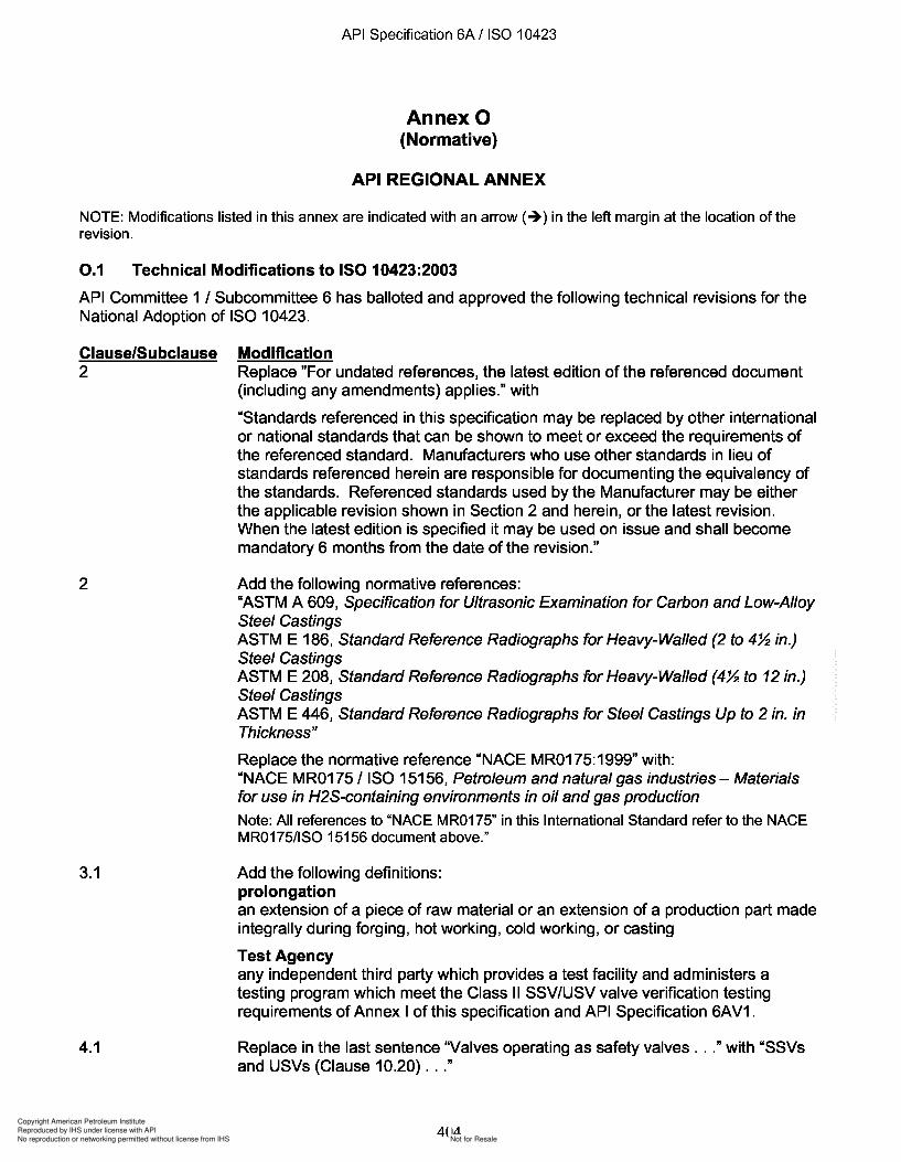
Copyright American Petroleum Institute
Reproduced by IHS under license with API
Not for ResaleNo reproduction or networking permitted without license from IHS
--`,,`,`,-`-`,,`,,`,`,,`---
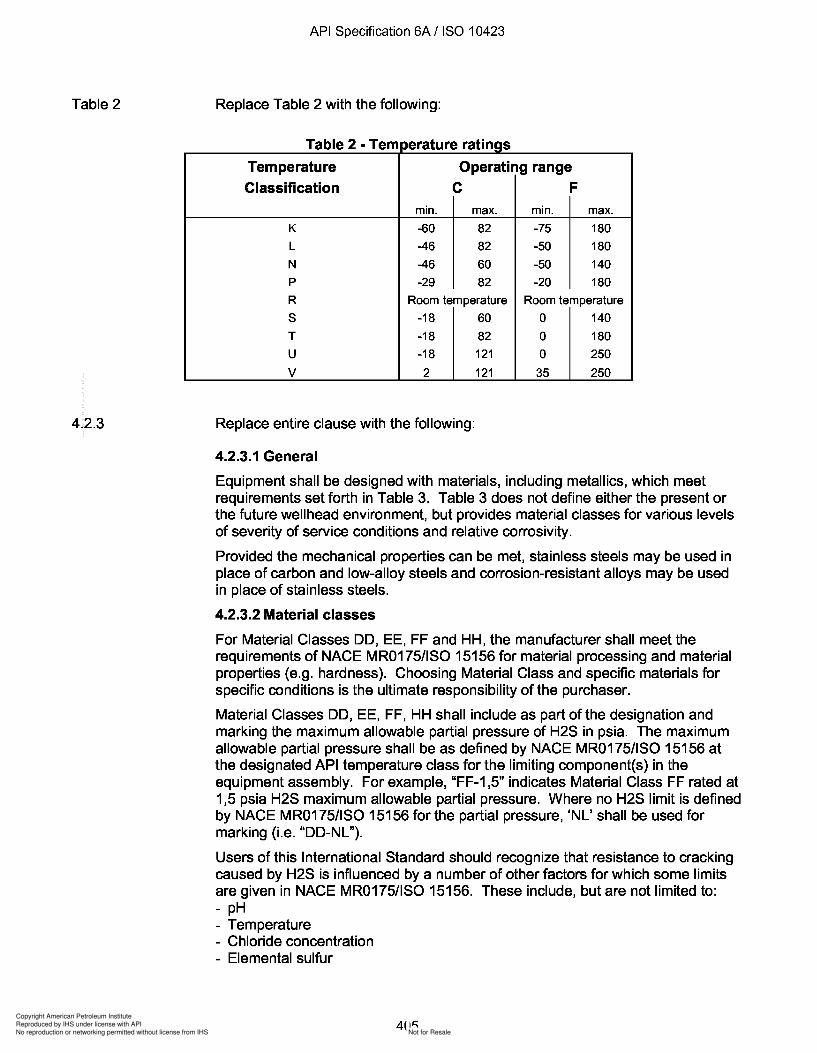
3
Copyright American Petroleum Institute
Reproduced by IHS under license with API
Not for ResaleNo reproduction or networking permitted without license from IHS
--`,,`,`,-`-`,,`,,`,`,,`---
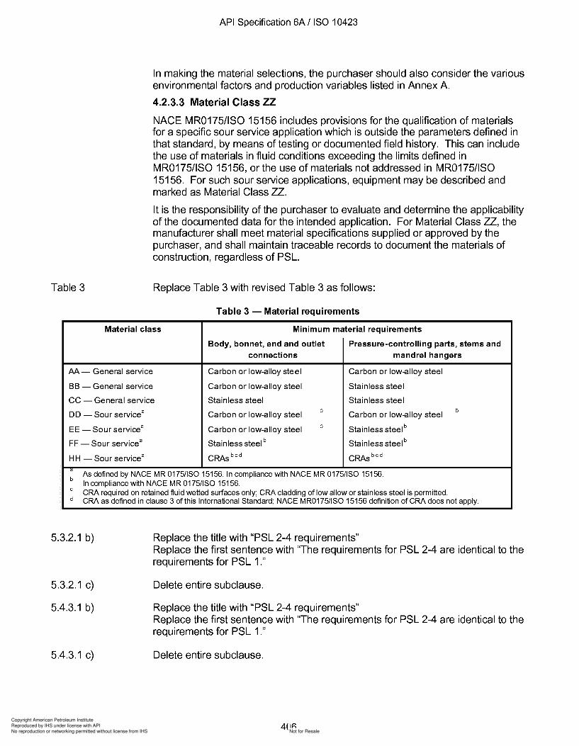
a
Copyright American Petroleum Institute
Reproduced by IHS under license with API
Not for ResaleNo reproduction or networking permitted without license from IHS
--`,,`,`,-`-`,,`,,`,`,,`---
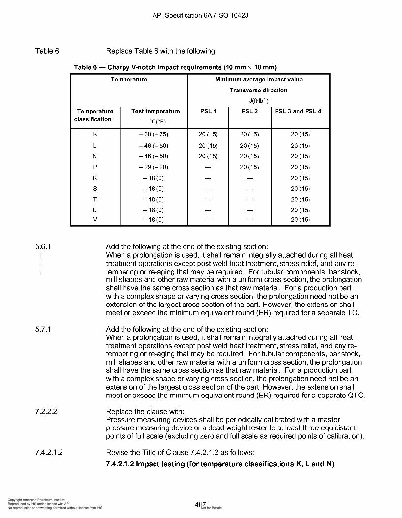
Copyright American Petroleum Institute
Reproduced by IHS under license with API
Not for ResaleNo reproduction or networking permitted without license from IHS
--`,,`,`,-`-`,,`,,`,`,,`---
Copyright American Petroleum Institute
Reproduced by IHS under license with API
Not for ResaleNo reproduction or networking permitted without license from IHS
--`,,`,`,-`-`,,`,,`,`,,`---
Copyright American Petroleum Institute
Reproduced by IHS under license with API
Not for ResaleNo reproduction or networking permitted without license from IHS
--`,,`,`,-`-`,,`,,`,`,,`---
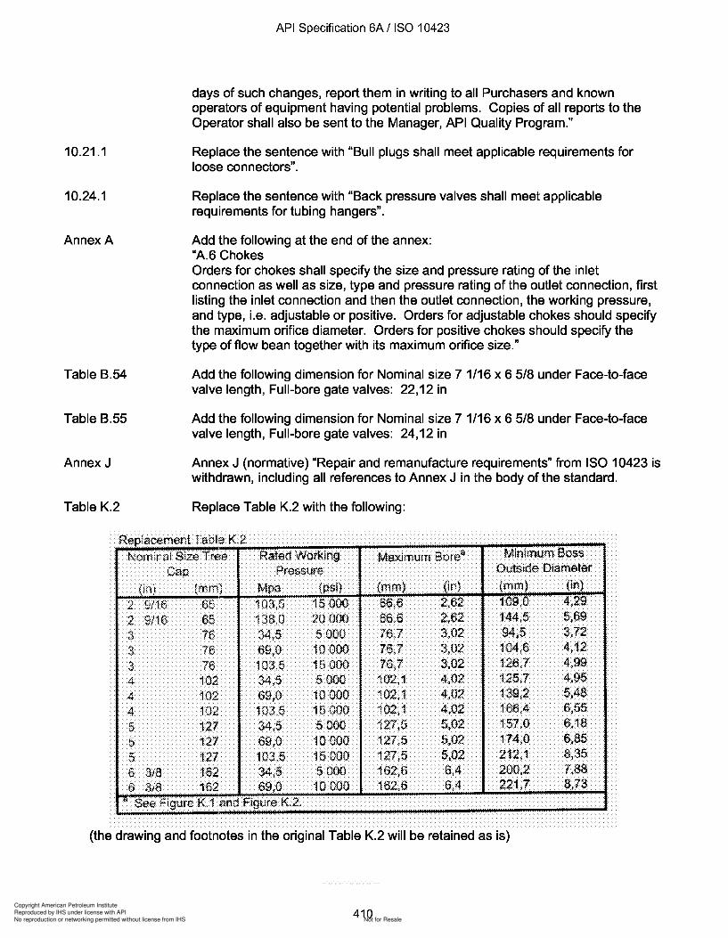
Copyright American Petroleum Institute
Reproduced by IHS under license with API
Not for ResaleNo reproduction or networking permitted without license from IHS
--`,,`,`,-`-`,,`,,`,`,,`---
API Specification 6A / ISO 10423
days of such changes, report them in writing to all Purchasers and knownoperators of equipment having potential problems. Copies of all reports to theOperator shall also be sent to the Manager, API Quality Program."
10.21.1 Replace the sentence with "Bull plugs shall meet applicable requirements forloose connectors".
10.24.1 Replace the sentence with "Back pressure valves shall meet applicablerequirements for tubing hangers".
AnnexA Add the following at the end of the annex:"A.6 ChokesOrders for chokes shall specify the size and pressure rating of the inletconnection as well as size, type and pressure rating of the outlet connection, firstlisting the inlet connection and then the outlet connection, the working pressure,and type, Le. adjustable or positive. Orders for adjustable chokes should specifythe maximum orifice diameter. Orders for positive chokes should specify thetype of flow bean together with its maximum orifice size."
Table B.54 Add the following dimension for Nominal size 7 1/16 x 6 5/8 under Face-to-facevalve length, Full-bore gate valves: 22,12 in
Table B.55 Add the following dimension for Nominal size 7 1/16 x 6 5/8 under Face-to-facevalve length, Full-bore gate valves: 24,12 in
Annex J Annex J (normative) "Repair and remanufacture requirements" from ISO 10423 iswithdrawn, including all references to Annex J in the body of the standard.
Table K.2 Replace Table K.2 with the following:
Minimum BossOutside Diameter
Maximum Borea
(pSi) (mm) (irlL (mm) (in)
15000 66,6 2,62 109,0 4,29
20000 66,6 2,62 144,5 5,69
5 000 76,7 3,02 94,5 3,72
10000 76,7 3,02 104,6 4,1215 000 76,7 3.02 126,7 4,995000 102,1 4,02 125,7 4.95
10000 102,1 4,02 139,2 5,48
15000 102,1 4,02 166,4 6,55
5000 127,5 5,02 157,0 6,18
10000 127,5 5,02 174,0 6,85
15000 127,5 5,02 212,1 8,355000 162,6 6,4 200.2 7.88
10000 162,6 6,4 221,7 8,73
2 9/16 6f 103,52 9/16 65 138,03 76 34,53 7669,03 76 103,54 102 34,54 102 69,04 102 103,55 127 34,55 127 69,05 127 103,56 318 162 34,56 3iB 162 13~,()
NOOiina! Size Tr£le Rated Work.ingCap Pressure
(fn) (mm)Mpa
Replacement Tabla K.2
« See Figure K 1 and Figure K.2.
(the drawing and footnotes in the original Table K.2 will be retained as is)
410
10.21.1
10.24.1
AnnexA
Table B.54
Table B.55
Annex J
Table K.2
API Specification 6A / ISO 10423
days of such changes, report them in writing to all Purchasers and known operators of equipment having potential problems. Copies of all reports to the Operator shall also be sent to the Manager, API Quality Program."
Replace the sentence with "Bull plugs shall meet applicable requirements for loose connectors".
Replace the sentence with "Back pressure valves shall meet applicable requirements for tubing hangers".
Add the following at the end of the annex: "A.6 Chokes Orders for chokes shall specify the size and pressure rating of the inlet connection as well as size, type and pressure rating of the outlet connection, first listing the inlet connection and then the outlet connection, the working pressure, and type, i.e. adjustable or positive. Orders for adjustable chokes should specify the maximum orifice diameter. Orders for positive chokes should specify the type of flow bean together with its maximum orifice size."
Add the following dimension for Nominal size 7 1/16 x 6 5/8 under Face-to-face valve length, Full-bore gate valves: 22,12 in
Add the following dimension for Nominal size 7 1/16 x 6 5/8 under Face-to-face valve length, Full-bore gate valves: 24,12 in
Annex J (normative) "Repair and remanufacture requirements" from ISO 10423 is withdrawn, including all references to Annex J in the body of the standard.
Replace Table K.2 with the following:
Replacement Tabl::> K 2 , . , -NOOiina! Size Tr£le Rated Work.ing Maximum Borea Minimum Boss
Cap Pressure Outside Diameter
(~n) (mm) Mpa (psi) (rnm) HrlL (mm) (in)
2 9/16 Bf 103,5 15000 66,6 2,62 109,0 4,29
2 9116 65 138,0 2QOOO 66,6 2,62 144,5 5,69
3 76 34,5 5 000 76,7 3,02 94,5 3.72
3 76 69,0 10000 16,7 3,02 104,6 4,12 3 76 103,5 15 000 76,7 3.02 126,7 4,99
4 102 34,5 5000 102,1 4,02 125.] 4,95 4 102 69,0 10 000 102,1 4,02 139,2 5,48
4 102 103.,5 15000 102,1 4,02 166,4 6,55
5 127 34,5 5000 127,5 5.02 157,0 6,18
5 127 69,0 10000 127,5 5,02 174,0 6,85
5 127 103,5 15000 127,5 5,02 212,1 8,35
6 3/8 162 34,5 5000 162,6 6,4 200.2 7,88 6 3iB 162 13~,() 10000 162,6 6,4 221,7 8,73
« See Figure K 1 and Figure K.2.
(the drawing and footnotes in the original Table K.2 will be retained as is)
410
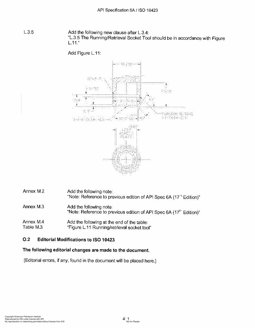
Copyright American Petroleum Institute
Reproduced by IHS under license with API
Not for ResaleNo reproduction or networking permitted without license from IHS
--`,,`,`,-`-`,,`,,`,`,,`---
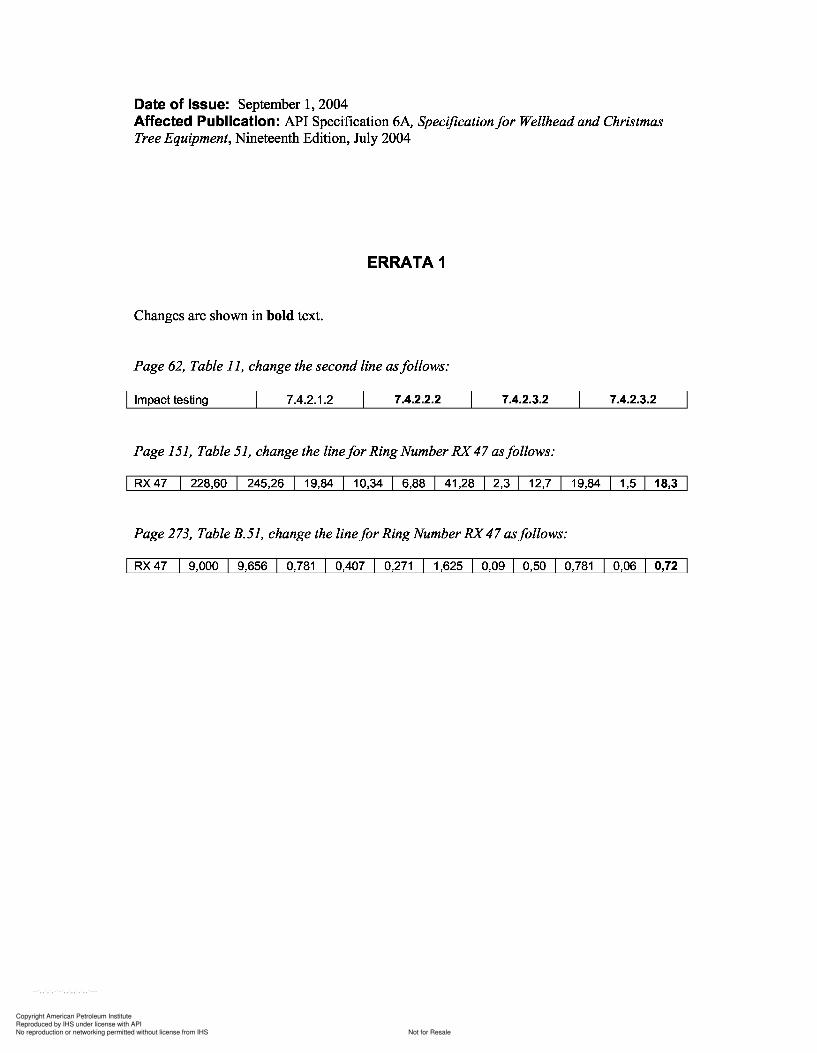
151, 51,
273,
Copyright American Petroleum Institute
Reproduced by IHS under license with API
Not for ResaleNo reproduction or networking permitted without license from IHS
--`,,`,`,-`-`,,`,,`,`,,`---
Date of Issue: September 1,2004Affected Publication: API Specification 6A, Specificationfor Wellhead and ChristmasTree Equipment, Nineteenth Edition, July 2004
ERRATA 1
Changes are shown in bold text.
Page 62, Table 11, change the second line asfollows:
I Impact testing 7.4.2.1.2 7.4.2.2.2 7.4.2.3.2 7.4.2.3.2
Page 151, Table 51, change the linefor Ring Number RX47 asfollows:
I RX47 228,60 245,26 19,84 10,34 6,88 41,28 2,3 12,7 19,84 1,5 18,3
Page 273, Table B.51, change the linefor Ring Number RX47 asfollows:
I RX 47 9,000 9,656 0,781 0,407 0,271 1,625 0,09 0,50 0,781 0,06 0,72
Date of Issue: September 1,2004 Affected Publication: API Specification 6A, Specification/or Wellhead and Christmas Tree Equipment, Nineteenth Edition, July 2004
ERRATA 1
Changes are shown in bold text.
Page 62, Table 11, change the second line as/ollows:
I Impact testing 7.4.2.1.2 7.4.2.2.2 7.4.2.3.2 7.4.2.3.2
Page 151, Table 51, change the line/or Ring Number RX 47 as/ollows:
I RX47 228,60 245,26 19,84 10,34 6,88 41,28 I 2,3 I 12,7 19,84 I 1,5 I 18,3
Page 273, Table B.51, change the line/or Ring Number RX 47 as/ollows:
I RX 47 9,000 9,656 0,781 0,407 0,271 1,625 I 0,09 I 0,50 0,781 0,06 0,72

Copyright American Petroleum Institute
Reproduced by IHS under license with API
Not for ResaleNo reproduction or networking permitted without license from IHS
--`,,`,`,-`-`,,`,,`,`,,`---
Copyright American Petroleum Institute
Reproduced by IHS under license with API
Not for ResaleNo reproduction or networking permitted without license from IHS
--`,,`,`,-`-`,,`,,`,`,,`---
API Specification 6A / ISO 10423
Bibliography
[1] ISO 31 (all parts), Quantities and units
[2] ISO 10419, Petroleum and natural gas industries - Drilling and production equipment - Installation,maintenance and repair of surface safety valves and underwater safety valves offshore
[3] ISO 10433, Petroleum and natural gas industries - Drilling and production equipment - Specification forwellhead surface safety valves and underwater safety valves for offshore service
[4] ISO 13628-3, Petroleum and natural gas industries - Design and operation of subsea productionsystems - Part 3: Through flowline (TFL) systems
[5] API Bul 5A: Information on dimensional data for sharp-thread casing and tubing, second edition, 1944
[6] API Spec 5CT, Specification for casing and tubing (U.S. customary units), sixth edition, October 1998,errata May 1999, and previous editions
[7] API Spec 6A, Specification for wellhead and christmas tree equipment, seventeenth edition, February 1996,errata and Supplement December 1996
[8] API TR 6AF, Technical report on capabilities ofAPI flanges under combinations of load
[9] API TR 6AF1, Technical report on temperature derating ofAPI flanges under combination of loading
[10] API TR 6AF2, Technical report on capabilities ofAPI integral flanges under combination of loading
[11] API Spec 6AV1, Specification for verification test of wellhead surface safety valves and underwater safetyvalves for offshore service, first edition, February 1996
[12] API Spec 6FA, Specification for fire test for valves
[13] API Spec 140, Specification for wellhead surface safety valves and underwater safety valves for offshoreservices, ninth edition, June 1994
[14] API RP 14H, Recommended practice for installation, maintenance, and repair of surface safety valves andunderwater safety valves offshore, fourth edition, July 1994
[15] ASME B1.5, ACME screw threads
[16] ASME B16.5, Pipe flanges and flanged fittings NPS 1/2 through NPS 24
[17] ASME B16.34, Valves -Flanged, threaded, and welding end
[18] ASME B18.2.2, Square and hex nuts (inch series)
[19] ASME, Boiler and Pressure Vessel Code:1998, Section II, Materials
[20] ASME SPPE 1, Quality assurance and certification of safety and pollution prevention equipment used inoffshore oil and gas operations
[21] ASTM E 21, Standard test methods for elevated temperature tension tests of metallic materials
412
API Specification 6A / ISO 10423
Bibliography
[1] ISO 31 (all parts), Quantities and units
[2] ISO 10419, Petroleum and natural gas industries - Drilling and production equipment - Installation, maintenance and repair of surface safety valves and underwater safety valves offshore
[3] ISO 10433, Petroleum and natural gas industries - Drilling and production equipment - Specification for wellhead surface safety valves and underwater safety valves for offshore service
[4] ISO 13628-3, Petroleum and natural gas industries - Design and operation of subsea production systems - Part 3: Through flowline (TFL) systems
[S] API Bul SA: Information on dimensional data for sharp-thread casing and tubing, second edition, 1944
[6] API Spec SCT, Specification for casing and tubing (U.S. customary units), sixth edition, October 1998, errata May 1999, and previous editions
[7] API Spec 6A, Specification for wellhead and christmas tree equipment, seventeenth edition, February 1996, errata and Supplement December 1996
[8] API TR 6AF, Technical report on capabilities of API flanges under combinations of load
[9] API TR 6AF1, Technical report on temperature derating of API flanges under combination of loading
[10] API TR 6AF2, Technical report on capabilities of API integral flanges under combination of loading
[11] API Spec 6AV1, Specification for verification test of wellhead surface safety valves and underwater safety valves for offshore service, first edition, February 1996
[12] API Spec 6FA, Specification for fire test for valves
[13] API Spec 140, Specification for wellhead surface safety valves and underwater safety valves for offshore services, ninth edition, June 1994
[14] API RP 14H, Recommended practice for installation, maintenance, and repair of surface safety valves and underwater safety valves offshore, fourth edition, July 1994
[1S] ASME B1.S, ACME screw threads
[16] ASME B16.S, Pipe flanges and flanged fittings NPS 1/2 through NPS 24
[17] ASME B16.34, Valves -Flanged, threaded, and welding end
[18] ASME B18.2.2, Square and hex nuts (inch series)
[19] ASME, Boiler and Pressure Vessel Code:1998, Section II, Materials
[20] ASME SPPE 1, Quality assurance and certification of safety and pollution prevention equipment used in offshore oil and gas operations
[21] ASTM E 21, Standard test methods for elevated temperature tension tests of metallic materials
412

Copyright American Petroleum Institute
Reproduced by IHS under license with API
Not for ResaleNo reproduction or networking permitted without license from IHS
--`,,`,`,-`-`,,`,,`,`,,`---

Copyright American Petroleum Institute
Reproduced by IHS under license with API
Not for ResaleNo reproduction or networking permitted without license from IHS
--`,,`,`,-`-`,,`,,`,`,,`---