6. kessler 213-220
TRANSCRIPT
© Faculty of Mechanical Engineering, Belgrade. All rights reserved FME Transactions (2006) 34, 213-220 213
Franz Kessler Professor
University of Leoben Chair for Conveying Technology and
Design Methods
Recent developments in the field of bulk conveying Existing products are continuously enhanced by taking regard for technical and economical aspects. Materials are used more efficient, production techniques become optimised and machinery gets easier to maintain. Because of requirements from the market, new products evolve. All of this is also true for the field of bulk conveying technologies. Examples of how to enhance single components for bulk conveying systems are shown. Improvements of components are discussed by taking a look at transfer chutes. The optimisation of the material flow at the transfer point is conducted by use of special simulation programs. A completely new system for bulk conveying was developed over the past few years by Doppelmayr/Austria with support by the University of Leoben. This system is a combination between belt conveyor and cable car. Keywords: chutes, simulation, belt conveyor, RopeCon, bulk handling terminal, rapid loading system.
1. INTRODUCTION
Existing products originating from different technical fields are continuously enhanced by taking regard for technical and economical aspects. Materials are used more efficient, production techniques become optimised, machinery gets easier to maintain and is showing a high grade of automation. Because of requirements from the market new products evolve. All of this is also true for the field of bulk conveying technologies [1, 2, 3].
Improvements of components of bulk handling equipment are discussed by taking a look at transfer chutes. The optimisation of the material flow at the transfer point is conducted by use of special simulation programs. These programs are quite complex and require long computation times, never the less produce results that allow for chute designs which show very high reliability. Those simulations take regard for the material properties in order to prevent a plugging of the chute by adequate construction. Different types of chutes are shown and discussed.
A completely new system for bulk conveying was developed over the past few years by the cable car company Doppelmayr/Austria and the University of Leoben. This system is a combination between belt conveyor and cable car. This conveyor by the name of “RopeCon” is a continuous conveyor for bulk materials and consists mainly of a flat fibre or steel inlet belt. Corrugated side walls on both sides of the belt guarantee a controlled transport of the bulk material and increase the filling profile. The belt in possessing diagonal beams attached to it in constant distances. Wheels (rope sheaves) are attached to these bars on
either side. The upper and lower belts are guided on two steel ropes by these wheels. The steel ropes are strained between the feeding and discharge stations. As for a conventional belt conveyor the belt is used as transport and pulling equipment. The conveyor is driven by a conventional drive pulley installed at the head or tail station.
By use of this new conveyor system very large distances (above 20km) can be overcome while placing supports in distances of above 2km.
The advantage of this continuous conveyor lies in the fact that it can easily overcome obstacles and in the low power consumption in regard to other means of bulk conveying. Finally existing installations are shown in several figures. 2. NEW DEVELOPMENT OF BULK HANDLING EQUIPMENT
2.1 Chutes in train loading systems - introduction
Immingham is one of Britain’s fastest growing ports and is operated by the UK’s leading ports group ABP (Associated British Ports). ABP’s largest expansion project is a £ 44,5M coal import terminal at Immingham – a single-berth extension to the existing Humber International Terminal.
In August 2004 ABP awarded the turn-key contract for the supply of the coal handling system to VOEST-ALPINE Materials Handling (VAMH) - a fully owned subsidiary of the SANDVIK mining and construction division.
2.2 Equipment
Beside a large number of belt conveyors and stacker reclaimers an automated train loading system was installed.
The installed system is one of the highest automated and efficient systems for train loading world-wide. The actual loading time of an approximately 400m long
Received: September 2006, Accepted: December 2006 Correspondence to: Dr Franz Kessler, Professor University of Leoben, Chair for Conveying Technologies and Design Methods, Franz-Josef-Strasse 18, A-8700 Leoben, Austria E-mail: [email protected]
214 ▪ VOL. 34, No 4, 2006 FME Transactions
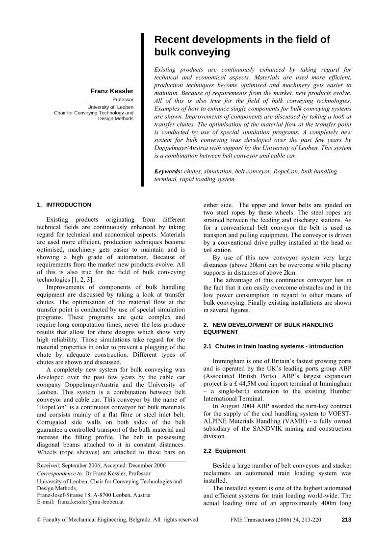
freight train with about 1600 tons of coal is approx. 20 minutes. In order to achieve the required Terminal-loading capacity of one train per hour, a second loading building is installed. Thus one plant can be loaded by the operator, while on the other plant part preparing- and terminating works can be done.
Each of the systems consists of a 42 ton reception bin with weighing system which feeds the hydraulic loading spout. The loading sequence had to consider varying parameters including different sized rail wagons and different density coals.
Figure 1. Two Rail load out building
2.3 Accuracy of the system The loading system is capable of accurately adjusting the height of the spout and accurately and consistently controlling the profile of the material loaded into the wagon. Loading accuracies are as follows: • The maximum variation in the total weight of
material transferred from the loading spout to each individual wagon is not less than 96% of the rated capacity for large wagons or 90% for small wagons.
• It is anticipated that it is possible to load the entire train to better than 98% of the rated capacity for large wagons and 95% for small wagons unless the wagons are volumetrically limited to less.
• No wagon will be loaded in excess of its rated capacity.
• For some types of coal and/or wagons these values will not be achievable due to the fact that the wagons may be volumetrically limited.
2.4 Design of the load out spout Design of the load out spout
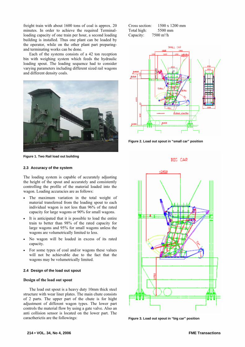
The load out spout is a heavy duty 10mm thick steel structure with wear liner plates. The main chute consists of 2 parts. The upper part of the chute is for hight adjustment of different wagon types. The lower part controls the material flow by using a gate valve. Also an anti collision sensor is located on the lower part. The caractherictis are the followings:
Cross section: 1500 x 1200 mm Total high: 5500 mm Capacity: 7500 m³/h
Figure 2. Load out spout in “small car” position
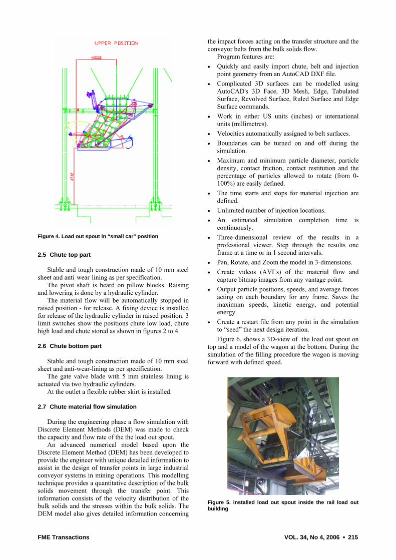
Figure 3. Load out spout in “big car” position
FME Transactions VOL. 34, No 4, 2006 ▪ 215
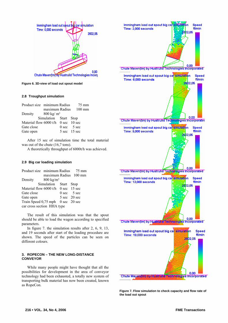
Figure 4. Load out spout in “small car” position
2.5 Chute top part
Stable and tough construction made of 10 mm steel sheet and anti-wear-lining as per specification.
The pivot shaft is beard on pillow blocks. Raising and lowering is done by a hydraulic cylinder.
The material flow will be automatically stopped in raised position - for release. A fixing device is installed for release of the hydraulic cylinder in raised position. 3 limit switches show the positions chute low load, chute high load and chute stored as shown in figures 2 to 4. 2.6 Chute bottom part
Stable and tough construction made of 10 mm steel sheet and anti-wear-lining as per specification.
The gate valve blade with 5 mm stainless lining is actuated via two hydraulic cylinders.
At the outlet a flexible rubber skirt is installed.
2.7 Chute material flow simulation
During the engineering phase a flow simulation with Discrete Element Methods (DEM) was made to check the capacity and flow rate of the the load out spout.
An advanced numerical model based upon the Discrete Element Method (DEM) has been developed to provide the engineer with unique detailed information to assist in the design of transfer points in large industrial conveyor systems in mining operations. This modelling technique provides a quantitative description of the bulk solids movement through the transfer point. This information consists of the velocity distribution of the bulk solids and the stresses within the bulk solids. The DEM model also gives detailed information concerning
the impact forces acting on the transfer structure and the conveyor belts from the bulk solids flow.
Program features are: • Quickly and easily import chute, belt and injection
point geometry from an AutoCAD DXF file. • Complicated 3D surfaces can be modelled using
AutoCAD's 3D Face, 3D Mesh, Edge, Tabulated Surface, Revolved Surface, Ruled Surface and Edge Surface commands.
• Work in either US units (inches) or international units (millimetres).
• Velocities automatically assigned to belt surfaces. • Boundaries can be turned on and off during the
simulation. • Maximum and minimum particle diameter, particle
density, contact friction, contact restitution and the percentage of particles allowed to rotate (from 0-100%) are easily defined.
• The time starts and stops for material injection are defined.
• Unlimited number of injection locations. • An estimated simulation completion time is
continuously. • Three-dimensional review of the results in a
professional viewer. Step through the results one frame at a time or in 1 second intervals.
• Pan, Rotate, and Zoom the model in 3-dimensions. • Create videos (AVI`s) of the material flow and
capture bitmap images from any vantage point. • Output particle positions, speeds, and average forces
acting on each boundary for any frame. Saves the maximum speeds, kinetic energy, and potential energy.
• Create a restart file from any point in the simulation to “seed” the next design iteration. Figure 6. shows a 3D-view of the load out spout on
top and a model of the wagon at the bottom. During the simulation of the filling procedure the wagon is moving forward with defined speed.
Figure 5. Installed load out spout inside the rail load out building
216 ▪ VOL. 34, No 4, 2006 FME Transactions
Figure 6. 3D-view of load out spout model 2.8 Troughput simulation Product size minimum Radius 75 mm maximum Radius 100 mm Density 800 kg/ m³ Simulation Start Stop Material flow 6000 t/h 0 sec 10 sec Gate close 0 sec 5 sec Gate open 5 sec 15 sec
After 15 sec of simulation time the total material was out of the chute (16,7 tons).
A theoretically throughput of 6000t/h was achieved. 2.9 Big car loading simulation Product size minimum Radius 75 mm maximum Radius 100 mm Density 800 kg/m³ Simulation Start Stop Material flow 6000 t/h 0 sec 15 sec Gate close 0 sec 5 sec Gate open 5 sec 20 sec Train Speed 0,75 mph 0 sec 20 sec car cross section HHA type
The result of this simulation was that the spout should be able to load the wagon according to specified parameters. In figure 7. the simulation results after 2, 6, 9, 13, and 19 seconds after start of the loading procedure are shown. The speed of the particles can be seen on different colours. 3. ROPECON – THE NEW LONG-DISTANCE CONVEYOR
While many people might have thought that all the possibilities for development in the area of conveyor technology had been exhausted, a totally new system of transporting bulk material has now been created, known as RopeCon.
Figure 7. Flow simulation to check capacity and flow rate of the load out spout

FME Transactions VOL. 34, No 4, 2006 ▪ 217
Figure 8. Fitting in the ropespan are the return/tension station, belt turning devices, re-rail track and track widener
Particularly where there is a need to transport material over ecologically sensitive terrain, therefore, this often leads to conflicts between economic necessity and environmental desirability.
The search for the ideal long-distance conveyor for bulk material led to an amazingly simple solution. It is based on a patented idea from Doppelmayr and combines the advantages of ropeway technology with the benefits of belt conveyors - the RopeCon long-distance conveyor was created. 3.1 Technical description “RopeCon”, the latest continuous conveying system for transporting all kinds of bulk materials over medium to long distances, essentially consists of a special conveyor belt with vulcanized corrugated side walls which runs on two track ropes in the upper and lower belts via running wheels attached to the belt. The belt performs a haulage and support function and, just like a conventional belt conveyor, is driven by a drive drum in the head or tail station. With this conveyor system it is possible to cover extremely long transport distances (up to 20 km), whereby the track ropes are carried by a suitable number of trestles, similar to the towers of a ropeway installation, and rigged at either end. Behind the drive or return station the belt is turned over so that the bottom belt can also run smoothly over the trestles. This also means that the soiled side of the belt faces upwards, thus preventing soiling of the track. Commercial grade, torque-balanced, galvanized, fully locked coil ropes are used as track ropes. Track rope support frames every 6m to 12m maintain the position of the track ropes in the rope spans and retain the spacing between the upper and lower belt. These frames also ensure that the material transported remains in place in the case of high wind velocities, thus preventing lift-off or de-ropement. In addition, a belt cover can be fitted to the frames if required. The four track ropes in combination with the steel support frames replace the bridge construction of a conventional conveyor.
Figure 9. Crossing of main road, river and railway The conveyor belt consists of a flat belt with multi-layer polyester-polyamide fabric or with steel cord reinforcement. It is fitted with corrugated side walls which keep the bulk material in position. Cross members are mounted at certain distances (to suit the loads) along the length of the conveyor to hold the wheel sets (rope sheaves). These wheel sets are supported by the track ropes which run along the sides of the conveyor belt. The high side plates on the wheels ensure the precise tracking of the belt even in the case of side winds. The wheels are made of high-grade polyamide which has optimal rolling resistance and is UV resistant. The wheels are inspected in the loading station, so no maintenance is required along the track and thus no complex catwalks are necessary.
Figure 10. Detail view with track rope support frames and wheels rollers 3.2 The benefits of the RopeCon • Long distances of up to 20 km • High transport capacity of up to 3,000 t/h • Easy way of crossing obstacles such as rivers,
gullies, etc. • Extremely long distances between trestles: up to
500m • No maintenance parts along the track (no catwalks
required) • Significantly lower kinetic resistances than with
conventional conveyor belts

218 ▪ VOL. 34, No 4, 2006 FME Transactions
• Minimal noise emission • No preparation of the track necessary, i.e. no tree
clearing, no bridges, no cuttings, no tunnels • Minimum time and effort required for removal • Not possible for the conveyor belt to skew • No belt guiding devices required and therefore no
damage to belt edges (increased service life of conveyor belt)
• Sturdy and extremely low-maintenance construction • Corrosion protection work reduced to a minimum
Figure 11. Detail view with track rope support frames and wheels rollers 3.3 The prototype in Strengen/Austria The prototype was built for the "Strengen Bypass" project. In order to develop a new conveyor system for series production it was essential to subject RopeCon to the harshest test conditions possible. The final section of the S16 Arlberg expressway between Tyrol and Vorarlberg is currently being completed with the "Strengen Bypass" construction project. The key feature of this final leg is the twin-section Strengen Tunnel which is approx. 5.8 km in length. It had originally been planned that the excavation waste from the tunnel would be transported by truck from both the eastern and western ends of the tunnel and taken to a dump site. At short notice ARGE Tunnel Strengen awarded Doubrava and Doppelmayr a contract to install the continuous conveyor system "RopeCon" at the western end of the tunnel. The authorities and local residents were immediately convinced of the advantages (emissions reduced to a minimum), which meant that the project planning and installation could be completed within a very short space of time. The transport costs have been reduced, the 115,000 truck journeys no longer required mean a major reduction in environmental impact as far as noise and pollution are concerned since over 100,000 litres of fuel have been saved.
The situation on site is predestined for the construction of RopeCon. The installation crosses the B316 Arlberg national highway, the Rosanna River and Arlberg West railway line. 3.4 Brief description of the installation The waste material produced from the blasting work in the tunnel is transported from the twin tunnels to the loading station by dumper truck and tipped into the loading bin. From there it is metered and fed into the single-jaw crusher with the aid of a reciprocating feeder. The crushed material is then transferred to the RopeCon via a vibrating feed chute.
3.5 Comparison of cross section and masses - Conventional Conveyor versus RopeCon
Cross section: conventional belt conveyor
Cross section: RopeCon
Figure 12. Conventional Conveyor bridge vs. RopeCon-System
In Fig.12. it can be seen, that the cross sectional area of the RopeCon is only 30% of a conventional belt conveyor.
At the same belt speed and mass flow, RopeCon has only 90% of moving masses and 30% of total weight of support structures. 3.6 Experimental tests and comparison with conventional belt conveyors – measurement of the sound pressure level
The Department of Conveying Technology of the University of Leoben carried out experimental tests at the RopeCon-System in Strengen. The sound pressure level of the RopeCon-System and two conventional belt conveyors was measured along the transport track at a belt speed of 2.62 m/s.
RopeCon showed a maximum value between 55 and 60 dB(A) in a distance of 1 m.
The two conventional belt conveyors had between 70 and 77 dB(A) in the same distance.
This can be explained by the bigger distance between the rollers (wheels) and the lower number of bearings of the RopeCon compared to conventional belt conveyors. Additional, noise which results from the movement of the rollers on the ropes is much lower than the noise of a belt running over idlers.

FME Transactions VOL. 34, No 4, 2006 ▪ 219
Figure 13. Measurement of the sound pressure level
The sound emission of the RopeCon-System has no
impact on the environment in medium distances. According to Austrian law the installation of a RopeCon is allowed in 10 m minimum distance to living areas. (This is not valid for feeding and discharge stations)
A comparison between the RopeCon and conventional belt conveyors with similar conveying capacities shows a 3-times higher sound emission of the conventional belt conveyor. 3.7 Comparison of the required drive power RopeCon versus conventional belt conveyor
The required mechanical power, resistance forces and belt tensile forces were measured at the RopeCon-prototype.
Based on the experimental results a computer program was designed, which allows a calculation of the required drive power of the RopeCon at different belt speeds and transport length.
A comparison between RopeCon and conventional belt conveyors was carried out for different conveying distances, a belt speed of 3.35 m/s and a transport capacity of 1000 t/h. The results are shown in figure 14.
0
100
200
300
400
500
600
700
0 1000 2000 3000 4000 5000 6000 7000
Conveying distance [m]
Driv
e po
wer
[kW
]
RopeCon empty
RopeCon loaded
Conventional empty
Conventional loaded
Figure 14. Comparison of required drive power – RopeCon versus conventional belt conveyor
In both operating modes, empty and loaded, RopeCon shows lower values for the required drive power. The saving of drive power is around 50%. This advantage increases with bigger transport capacities and conveying distances.
Measurements also have shown that the turn-over of the belt on both ends creates the highest travel
resistance of the system which increases the required drive power significantly.
3.8 New RopeCon in Upper Austria
For the next RopeCon which was installed in Upper Austria the belt turn-over had to be optimized. The goal was to eliminate the guide rails within the belt turn-over section and allow an unguided turn-over. The big problem in this design is that the wheels, moving out of the unguided turn-over section, have to find there way precisely to the support ropes.
At the Department of Conveying Technology, University of Leoben, all possibilities of an unguided belt turn-over were theoretically and experimentally investigated.
The result was a new design which guarantees a high safety in operation. The minimum length of the turn-over section followed from simulations of the additional belt stresses in this section.
Figure 15. Test facility for the unguided belt turn-over Figure 15. shows the test facility in the laboratory. Meanwhile a new RopeCon is installed in Upper Austria, which transports bulk material from one end of a plant to the other.
Figure 16. General view of the RopeCon in Upper Austria
The feeding station of the RopeCon is on the right edge in figure 16. The conveyor is crossing roads, buildings, trees, a river and other conveyor routes and ends on top of a tower which is located at the left edge of the figure. Looking at all these obstacles the advantage of this system, compared to other conveyors, is evident. The RopeCon needs just one pillar along its track but all other conveying systems need expensive substructures and bridges.
Based on the theoretical and experimental results of the University of Leoben the belt turn-over for this RopeCon was built. (Figure 17.)

220 ▪ VOL. 34, No 4, 2006 FME Transactions
Figure 17. Unguided belt turn-over in Upper Austria
Measurements of the required drive power at the new design confirmed the successful development of the unguided belt turn-over. The drive power is reduced to 30% compared to a conventional belt conveyor.
Figure 18. View from the discharge station on top of a tower back to conveyor track
Figure 19. View from the loading station with belt turn-over section and conveyor track
4. CONCLUSION In recent years there were many new developments in bulk material handling systems but only two of them are discussed in this paper. The first example which is dealing with chutes shows a modern design of a load out spout for an automated train loading system. The chutes are checked by a simulation program to guarantee the required material flow. The second example gives a view into the new RopeCon long-distance conveyor which combines the advantages of ropeway technology with the benefits of belt conveying technology. Total moving masses, weight of the support structure and required drive power of the RopeCon are significant lower compared to conventional belt conveyors. The sound emission of RopeCon is 3-times lower than the emission of a conventional belt conveyor. REFERENCES [1] Diethardt, P., Kessler, F.: Untersuchungen zum
Bewegungswiderstand von verschränkten Gurtwendungen, SCHÜTTGUT, Vol.10, No.6, pp. 446 – 452, 2004.
[2] Diethardt, P., Kessler F., Stoschka, M.: Berechnung der Antriebsleistung bei RopeCon-Systemen SCHÜTTGUT, Vol.10, No. 4, pp. 288 – 293, 2004.
[3] Pillichshammer, C., Trieb, H. Flebbe, H.: RopeCon – das neue Landstreckenförderband SCHÜTTGUT, Vol.9, No. 2, pp. 108 – 111, 2003.