60 ghz ecr source status - princeton university
TRANSCRIPT
Nuf
act1
1XI
IIth
Inte
rnat
iona
l Wor
ksho
p on
Neu
trino
Fac
torie
s, S
uper
Bea
ms
and
Bet
a B
eam
sC
ER
N /
UN
IGE
, 201
1, 1
st-6
thA
ugus
t T. LamyM. Marie-Jeanne, P. Sortais, T. Thuillier
Laboratoire de Physique Subatomique et de Cosmologie, Grenoble – France
I.V. Izotov, A. V. Sidorov, V. A. Skalyga, V. G. ZorinИнститут Прикладной Физики - RAS, Nizhny Novgorod – Russia
F. Debray, C. Trophime, N. Vidal Laboratoire National des Champs Magnétiques Intenses, Grenoble – France
60 GHzECR source status
* Sixty GHz ECR Ion Source using Megawatt Magnets
T. Lamy – LPSC - Nufact11, CERN/UNIGE, 2011, 1st - 6th August
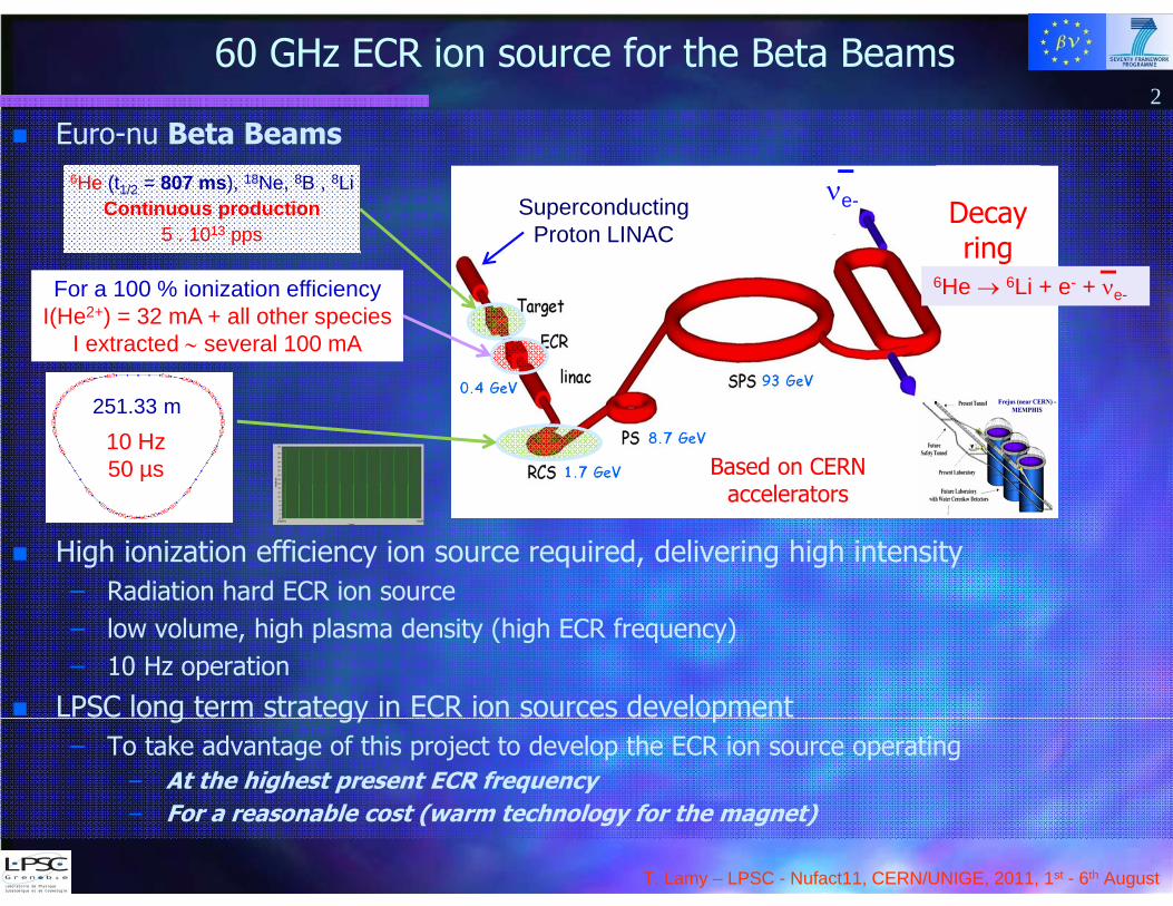
Euro-nu Beta Beams
High ionization efficiency ion source required, delivering high intensity– Radiation hard ECR ion source– low volume, high plasma density (high ECR frequency)– 10 Hz operation
LPSC long term strategy in ECR ion sources development– To take advantage of this project to develop the ECR ion source operating
– At the highest present ECR frequency– For a reasonable cost (warm technology for the magnet)
Decayring
Based on CERN accelerators
60 GHz ECR ion source for the Beta Beams
251.33 m
10 Hz50 µs
For a 100 % ionization efficiencyI(He2+) = 32 mA + all other species
I extracted several 100 mA
6He 6Li + e- + e-
6He (t1/2 = 807 ms), 18Ne, 8B , 8LiContinuous production
5 . 1013 pps
e-
2
SuperconductingProton LINAC
T. Lamy – LPSC - Nufact11, CERN/UNIGE, 2011, 1st - 6th August
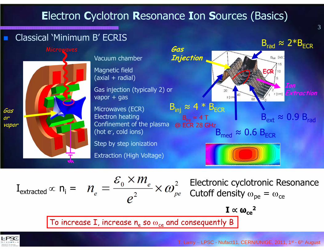
Classical ‘Minimum B’ ECRIS
Electron Cyclotron Resonance Ion Sources (Basics)
Vacuum chamber
Magnetic field(axial + radial)
Gas injection (typically 2) or vapor + gas
Microwaves (ECR)Electron heatingConfinement of the plasma (hot e-, cold ions)
Step by step ionization
Extraction (High Voltage)
Microwaves
Gas or vapor
ECR
Brad ≈ 2*BECR
Binj ≈ 4 * BECR
Bmed ≈ 0.6 BECR
Bext ≈ 0.9 Brad
IonExtraction
Gas Injection
3
Binj = 4 T @ ECR 28 GHz
Iextracted ni = Electronic cyclotronic ResonanceCutoff density pe = ce
To increase I, increase ne so ce and consequently BI ∝ ωce
2
T. Lamy – LPSC - Nufact11, CERN/UNIGE, 2011, 1st - 6th August
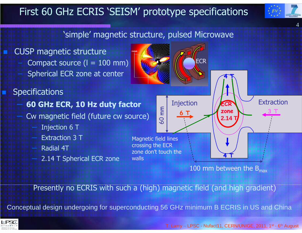
‘simple’ magnetic structure, pulsed Microwave
CUSP magnetic structure– Compact source (l = 100 mm)– Spherical ECR zone at center
First 60 GHz ECRIS ‘SEISM’ prototype specifications4
ECR
Specifications– 60 GHz ECR, 10 Hz duty factor– Cw magnetic field (future cw source)
– Injection 6 T
– Extraction 3 T
– Radial 4T– 2.14 T Spherical ECR zone
4 T
3 T6 T
4 T
Injection Extraction
Magnetic field linescrossing the ECR zone don’t touch the walls
60 m
m100 mm between the Bmax
ECRzone 2.14 T
Presently no ECRIS with such a (high) magnetic field (and high gradient)
Conceptual design undergoing for superconducting 56 GHz minimum B ECRIS in US and China
T. Lamy – LPSC - Nufact11, CERN/UNIGE, 2011, 1st - 6th August
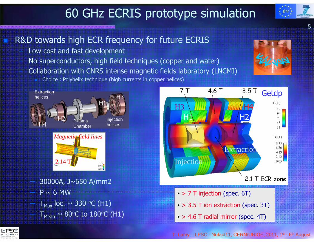
60 GHz ECRIS prototype simulation5
R&D towards high ECR frequency for future ECRIS– Low cost and fast development– No superconductors, high field techniques (copper and water)– Collaboration with CNRS intense magnetic fields laboratory (LNCMI)
Choice : Polyhelix technique (high currents in copper helices)
Magnetic field lines
2.14 T
• > 7 T injection (spec. 6T)
• > 3.5 T ion extraction (spec. 3T)
• > 4.6 T radial mirror (spec. 4T)
– 30000A, J~650 A/mm2
– P ~ 6 MW
– TMax loc. ~ 330 °C (H1)– TMean ~ 80°C to 180°C (H1)
InjectionExtraction
H1 H2H3 H4
Getdp
PlasmaChamber
Extraction helices
H4H2 injection
helices
H3H1
T. Lamy – LPSC - Nufact11, CERN/UNIGE, 2011, 1st - 6th August
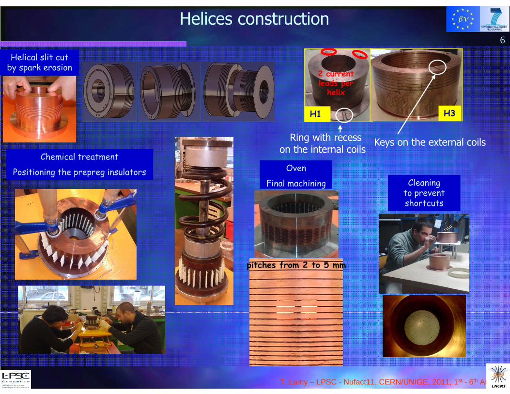
Helices construction
Helical slit cut by spark erosion
Chemical treatment
Positioning the prepreg insulators
6
H1 H3
2 current leads per
helix
Ring with recesson the internal coils
Keys on the external coils
Oven
Final machining
pitches from 2 to 5 mm
Cleaningto prevent shortcuts

T. Lamy – LPSC - Nufact11, CERN/UNIGE, 2011, 1st - 6th August
Prototype mechanical design7
2 sub-assemblieshelices and current leads The basic part: ‘exchanger’
CAD
Extraction Flange
Characteristics– Diameter 620 mm– Length 480 mm – 600 kg– 30 tons Repel force
T. Lamy – LPSC - Nufact11, CERN/UNIGE, 2011, 1st - 6th August
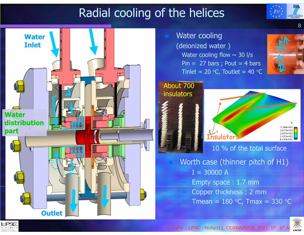
Water cooling(deionized water )
– Water cooling flow ~ 30 l/s– Pin = 27 bars ; Pout = 4 bars– Tinlet = 20 °C, Toutlet = 40 °C
WaterInlet
Waterdistributionpart
Outlet
Radial cooling of the helices8
Insulators
Worth case (thinner pitch of H1)– I = 30000 A– Empty space : 1.7 mm– Copper thickness : 2 mm– Tmean = 180 °C, Tmax = 330 °C
About 700insulators
10 % of the total surface
T. Lamy – LPSC - Nufact11, CERN/UNIGE, 2011, 1st - 6th August
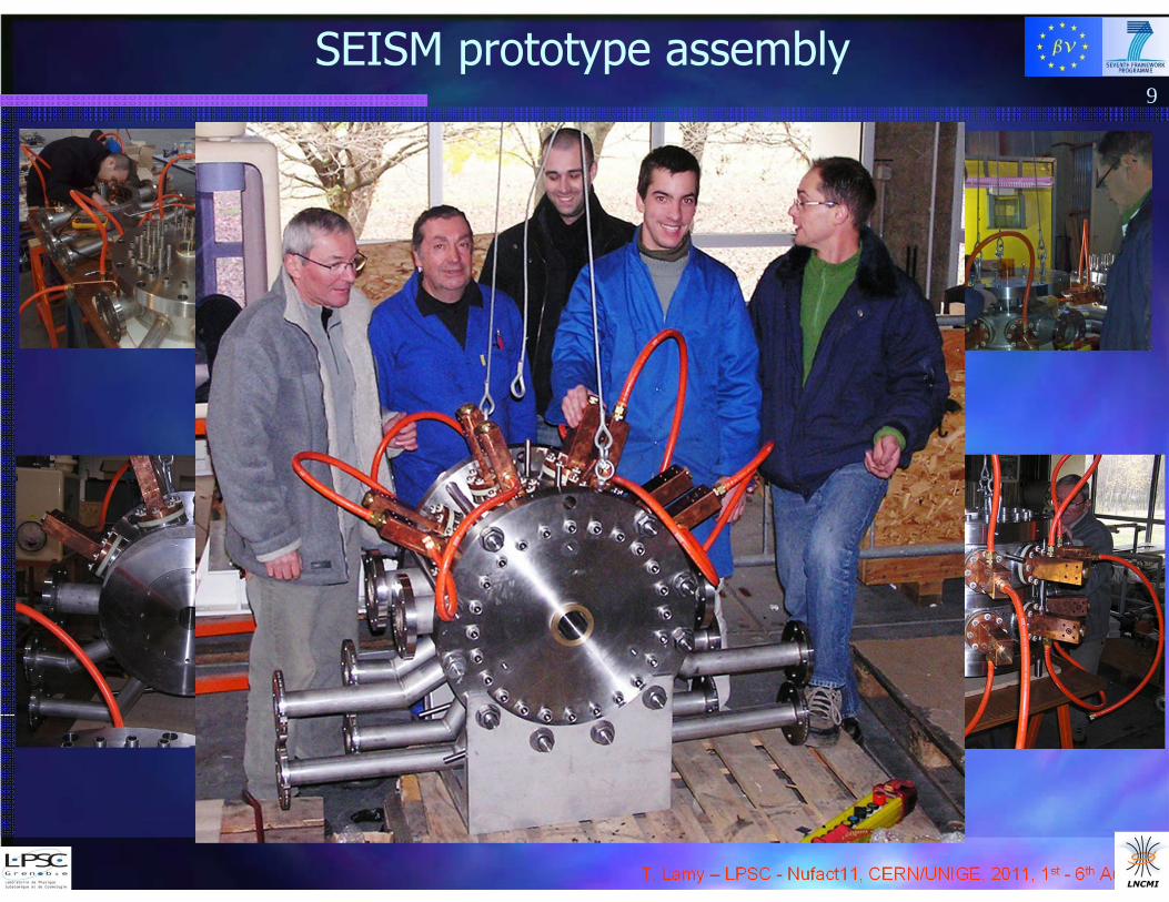
SEISM prototype assembly9
T. Lamy – LPSC - Nufact11, CERN/UNIGE, 2011, 1st - 6th August
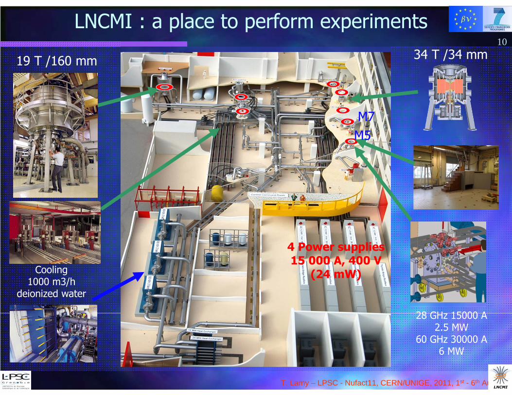
LNCMI : a place to perform experiments
19 T /160 mm 34 T /34 mm
Cooling1000 m3/h
deionized water
4 Power supplies15 000 A, 400 V
(24 mW)
28 GHz 15000 A2.5 MW
60 GHz 30000 A6 MW
M5M7
10
T. Lamy – LPSC - Nufact11, CERN/UNIGE, 2011, 1st - 6th August
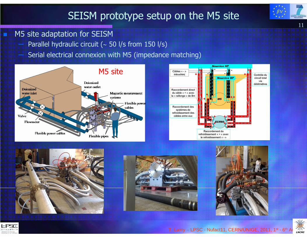
M5 site adaptation for SEISM– Parallel hydraulic circuit ( 50 l/s from 150 l/s)
– Serial electrical connexion with M5 (impedance matching)
SEISM prototype setup on the M5 site11
M5 site
T. Lamy – LPSC - Nufact11, CERN/UNIGE, 2011, 1st - 6th August
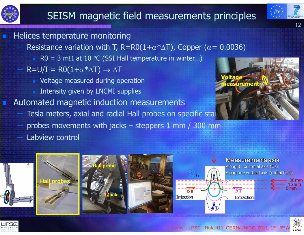
SEISM magnetic field measurements principles12
Helices temperature monitoring– Resistance variation with T, R=R0(1+*T), Copper (= 0.0036)
R0 = 3 m at 10 °C (SSI Hall temperature in winter...)
– R=U/I = R0(1+*T) T Voltage measured during operation
Intensity given by LNCMI supplies
Automated magnetic induction measurements– Tesla meters, axial and radial Hall probes on specific stands (calibrated on M5)– probes movements with jacks – steppers 1 mm / 300 mm– Labview control
Voltagemeasurement
Jack
Hall probe
Hall probes
T. Lamy – LPSC - Nufact11, CERN/UNIGE, 2011, 1st - 6th August
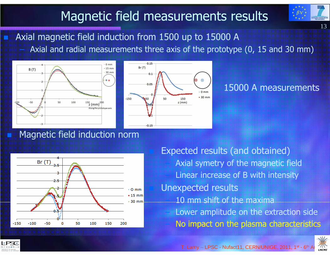
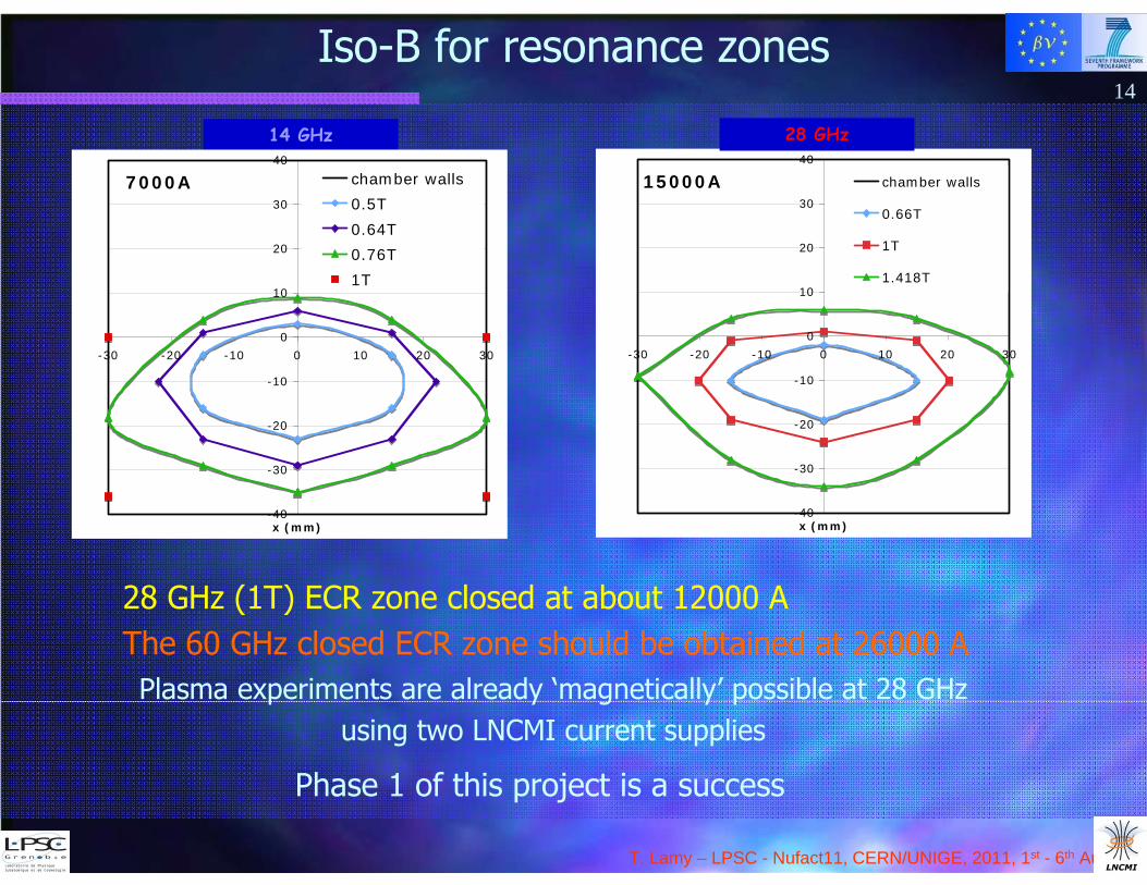
Magnetic field measurements results Axial magnetic field induction from 1500 up to 15000 A
– Axial and radial measurements three axis of the prototype (0, 15 and 30 mm)
13
Magnetic field induction norm
Expected results (and obtained)– Axial symetry of the magnetic field– Linear increase of B with intensity
Unexpected results– 10 mm shift of the maxima– Lower amplitude on the extraction side– No impact on the plasma characteristics
15000 A measurements
T. Lamy – LPSC - Nufact11, CERN/UNIGE, 2011, 1st - 6th August
15000A
-40
-30
-20
-10
0
10
20
30
40
-30 -20 -10 0 10 20 30
x (mm)
chamber walls
0.66T
1T
1.418T
28 GHz14 GHz
7000A
-40
-30
-20
-10
0
10
20
30
40
-30 -20 -10 0 10 20 30
x (mm)
chamber walls0.5T0.64T0.76T1T
Iso-B for resonance zones
Plasma experiments are already ‘magnetically’ possible at 28 GHzusing two LNCMI current supplies
Phase 1 of this project is a success
28 GHz (1T) ECR zone closed at about 12000 AThe 60 GHz closed ECR zone should be obtained at 26000 A
14

T. Lamy – LPSC - Nufact11, CERN/UNIGE, 2011, 1st - 6th August
Application for magnet time
Characterization of ion beams extracted from a 28 GHz ECR plasma in a split magnet
To progress towards 60 GHz ECR operation of the ECRIS- Simple beam line : magnetic spectrometer and beam characterization devices
- 10 kW 28 GHz gyrotron available from LPSC- A lot of safety issues (Microwaves, X rays, High voltage...)
After beam measurements (a few weeks)- Terminate magnetic field measurements from 15000 up to 30000 A- If gyrotron available : 60 GHz experiments
Accepted for 20 days 15
28 GHzwaveguide
High voltagering
Plasmachamber
Plasmaelectrode
Extractioninsulator
Pullerelectrode
Inside ECRIS 28 GHz prototype design
T. Lamy – LPSC - Nufact11, CERN/UNIGE, 2011, 1st - 6th August
Efficiencies and currents expected ...?16
Fast ionization, efficient ionization
High density necessary High ECR frequency (60 GHz) and high power density 60 GHz : cut-off density 4.46x10¹³ ions/cm3 to be compared with
2x10¹⁰ ions/cm3 He ...(5 x 10¹² in a 0.25 l (plasma): 2x10¹⁰ ions/cm3
(ratio 4.5 10-4) Multi-Ampères source !!!! Certainly avoid multi charged ions...
High intensity beam line will be required (mandatory...) But good news from Russia
8th International Workshop ‘Strong Microwaves and Terahertz Waves Sources and Applications’July 9 - 16, 2011 Nizhny Novgorod, Russia
1.6 mm extraction hole leads to 80% efficiency for He+ and only 300 mA total current
“Gas utilization efficiency optimization for short-pulsed ECR ion source”I. V. Izotov, V. A. Skalyga, V. G. Zorin (IAP Nizhny Novgorod)
T. Lamy – LPSC - Nufact11, CERN/UNIGE, 2011, 1st - 6th August
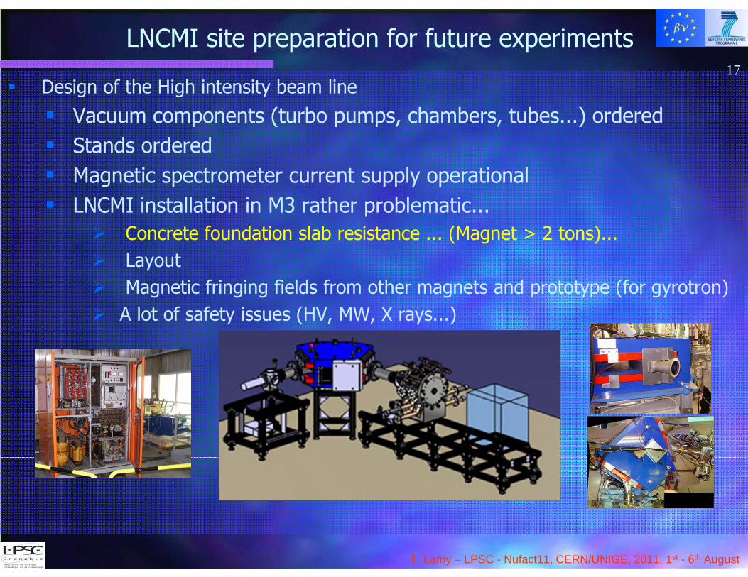
LNCMI site preparation for future experiments17
Design of the High intensity beam line
Vacuum components (turbo pumps, chambers, tubes...) ordered Stands ordered Magnetic spectrometer current supply operational LNCMI installation in M3 rather problematic...
Concrete foundation slab resistance ... (Magnet > 2 tons)... Layout Magnetic fringing fields from other magnets and prototype (for gyrotron) A lot of safety issues (HV, MW, X rays...)
T. Lamy – LPSC - Nufact11, CERN/UNIGE, 2011, 1st - 6th August
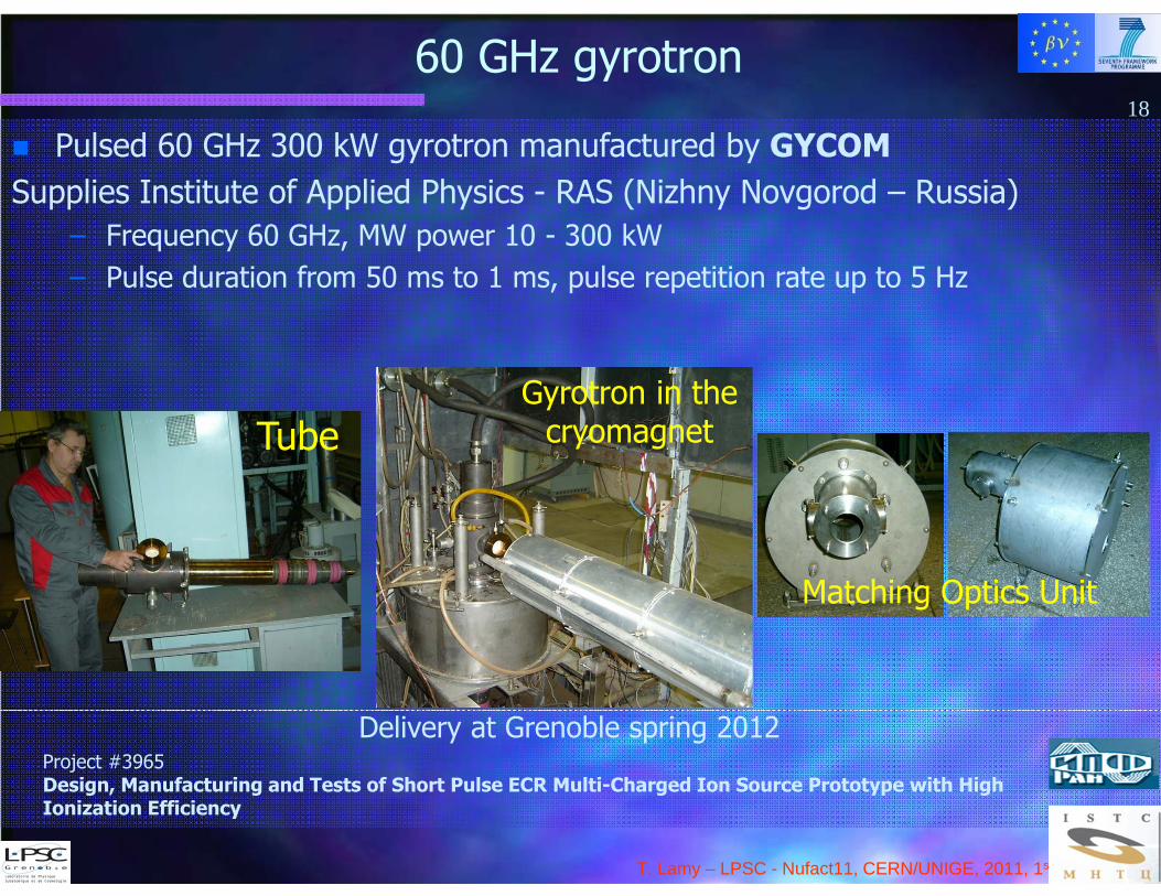
60 GHz gyrotron18
Pulsed 60 GHz 300 kW gyrotron manufactured by GYCOMSupplies Institute of Applied Physics - RAS (Nizhny Novgorod – Russia)
– Frequency 60 GHz, MW power 10 - 300 kW– Pulse duration from 50 ms to 1 ms, pulse repetition rate up to 5 Hz
TubeGyrotron in the
cryomagnet
Matching Optics Unit
Delivery at Grenoble spring 2012Project #3965Design, Manufacturing and Tests of Short Pulse ECR Multi-Charged Ion Source Prototype with High Ionization Efficiency
T. Lamy – LPSC - Nufact11, CERN/UNIGE, 2011, 1st - 6th August
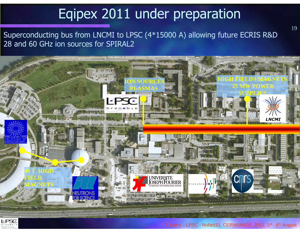
Eqipex 2011 under preparation
40 T HIGH FIELDMAGNETS
HIGH FIELDS MAGNETS25 MW POWER
SUPPLIES
ION SOURCESPLASMAS
Superconducting bus from LNCMI to LPSC (4*15000 A) allowing future ECRIS R&D28 and 60 GHz ion sources for SPIRAL2
19
T. Lamy – LPSC - Nufact11, CERN/UNIGE, 2011, 1st - 6th August
20
Thank you !
We acknowledge the financial support of the European Community under the European Commission Framework Programme 7 Design Study: EUROnu, Project Number 212372. The EC is not liable for any use that may be made of the information contained herein.