600r ribbon window system - efco corporationefcocorp.com/images/products/remote/instructions/y024 -...
TRANSCRIPT

600R Ribbon Window System
EFCO 2015 Page 1
Part Y024 September 2015

600R Ribbon Window System
EFCO 2015 Page 2
Section Page
1. General Notes and Guidelines…………………………………………………………………………………... 2. Parts Identification Charts……………………………………………………………………………………….. 3. Fabrication ………………………………………………………………………………………………………….
A. Screw Spline Method………………………………………………………………………………………. B. Shear Block Method - Verticals…………………………………………………………………………… C. “B” Type Installation Method - Verticals………………………………………………………………….. D. Shear Block Method - Horizontals………………………………………………………………………… E. “B” Type Installation Method - Horizontals……………………………………………………………….. F. Screw Spline Sill to Sub-sill……………………………………………………………………………….. G. Head Anchor Channel Clearance Hole…………………………………………………………………... H. Horizontal Weeps…………………………………………………………………………………………….
4. Unit Assembly……………………………………………………………………………………………………….. A. Screw Spline Assembly……………………………………………………………………………………. B. Shear Block Assembly……………………………………………………………………………………... C. “B” Type Head and Sill through Assembly……………………………………………………………….. D. SSG Expansion Mullion Assembly………………………………………………………………………..
5. Installation……………………………………………………………………………………………………………. A. Door Frame Installation…………………………………………………………………………………….. B. Sub-sill Fabrication and Installation………………………………………………………………………. C. Sub-sill and Frame Splices………………………………………………………………………………… D. Sealing………………………………………………………………………………………………………..
6. Glazing………………………………………………………………………………………………………………... 7. Face Covers…………………………………………………………………………………………………………..
3-5 6-9
10 11 12 13 13 14 14 14
15 16 17 18
19 20
21-22 22-24 25-33
34
Minimizing Condensation Note: Please reference EFCO’s “ Understanding Condensation” brochure which can be obtained through your EFCO representative. Condensation will form on any surface when unfavorable conditions (regarding interior temperature, relative humidity and exterior temperature) are present. When the formation of excessive condensation is a concern, it is highly recommended that a design professional is utilized to perform an analysis of the shop drawings to recommend the best possible installation methods. Please contact your EFCO representative for information on EFCO’s Thermal Analysis Services. Many current installation practices lead to an increase in the possibility of the formation of condensation. Though not all inclusive, the list of examples below illustrates conditions under which condensation is likely to occur:
1. Bridging the system thermal break with non-thermally broken metal flashing or lintels that are exposed to the exterior 2. System exposure to cold air cavities 3. Interior relative humidity levels not maintained at recommended levels, see EFCO’s “Understanding Condensation” brochure 4. Inadequate separation between system and surrounding condition at perimeter 5. Product combinations during the shop drawing stage that result in bridging thermal breaks of one or all products involved

600R Ribbon Window System
EFCO 2015 Page 3
Section 1: General Notes and Guidelines
HANDLING / STORING / PROTECTING ALUMINUM *The following guidelines are recommended to ensure early acceptance of your products and workmanship.*
A. HANDLE CAREFULLY - Store with adequate separation between components so the material will not rub together. Store the material off the ground.
Protect materials against weather elements and other construction trades. B. KEEP MATERIAL AWAY FROM WATER, MUD, AND SPRAY - Prevent cement, plaster, and other materials from contacting with and damaging the
finish. Do not allow moisture to be trapped between the finished surface and the wrapping material. C. PROTECT MATERIALS AFTER ERECTION - Wrap or erect screens of plastic sheeting over material. Cement, plaster, terrazzo, and other
alkaline materials are very harmful to the finish and are to be immediately removed with soap and water. Under no circumstances should these materials be allowed to dry or permanent staining may occur.
GENERAL GUIDELINES
*The following practices are recommended for all installations*
A. SHIPMENT VERIFICATION - Verify contents of all material shipments received upon their arrival. Verify quantity and correct finishes. Notify EFCO immediately of any discrepancies or damage that may have occurred. B. REVIEW CONTRACT DOCUMENTS – Become thoroughly familiar with the project. Check shop drawings, installation instructions, architectural
drawings and shipping lists. The shop drawings take precedence and include specific details for the project. Shop drawings govern when conflicting information exists in the assembly and installation instructions. Note any field verified notes on the shop drawings prior to installing. EFCO assembly and installation instructions are general in nature and cover only some of the conditions. C. PERIMETER CONDITIONS - Verify that all job site conditions and accompanying substrates receiving the installation are in accordance with the
contract documents. If deviations occur, notification must be given in writing to the general contractor and differences resolved before proceeding further with the installation in the area in question.
D. ISOLATION OF ALUMINUM - Prevent all aluminum from coming in direct contact with masonry or dissimilar materials by means of an appropriate primer.
Typical slab anchors may be set directly onto concrete surfaces in a block-out pocket at the edge of the slab. The block-out pocket is later filled in with grout thereby covering the slab anchor. In such cases, a heavy coat of zinc chromate or bituminous paint must be pre-applied to the slab anchor.
E. INSTALL ALL FRAMING MATERIAL PLUMB, LEVEL, AND TRUE – Proper alignment and relationships to benchmarks and column centerlines, as

600R Ribbon Window System
EFCO 2015 Page 4
Section 1: General Notes and Guidelines
F. SEALANT - All sealant must meet [ASTM C 920, CLASS 50]. For the purposes of these instructions, sealant is to be defined as the following: SEALANT - A weather resistant, gunnable liquid filler which when cured provides a resilient, flexible (± 50% movement capability min.) air and water seal between similar and dissimilar materials.
All sealant must be compatible with all surfaces on which adhesion is required, including other sealant surfaces. All frame surfaces should be clean, dry, dust, and frost free. If a primer is required, it must be applied to clean surfaces. All perimeter substrates shall be clean and properly treated to receive sealant. All sealants and primers must be applied according to the sealant manufacturers instructions and recommendations. This system is designed and has been tested to utilize silicone sealants at all internal joineries, i.e., gasket intersection, etc. It is the responsibility of the glazing contractor to submit a statement from the sealant manufacturer indicating that glass and glazing materials have been tested for compatibility and adhesion with glazing sealants, and interpreting test results relative to material performance, including recommendations for primers and substrate preparation required to obtain adhesion. The chemical compatibility of all glazing materials and framing sealants with each other and with like materials used in glass fabrication must be established.
G. STRUCTURAL SEALANT JOINTS - The maximum allowable size of the glass lite is controlled by the width and depth of the structural silicone joint combined with the specified design wind load (PSF or Pa). The stress on the structural silicone must not exceed 20 PSI (137 KPa) for a 6:1 safety factor. In order to determine the structural silicone sealant contact width or bite which adheres the glass to the frame, a calculation must be performed on a job by job basis. The formula which determines the sealant width is based on using a trapezoidal load distribution rule. This formula is expressed as follows:
Structural Sealant = 0.5 x Short Span (ft) x Wind load (lb./ft.²) Bite or Contact Width (in) Sealant Design Strength (=20 lb./in.²) x 12 in./ft.
Example: Lite size is 48” x 60” and wind load for the project is 60 psf.
Structural Sealant = 0.5 x 4’ x 60 PSF or 120 or .500” Bite or Contact Width (in) 20 x 12 240
Sealant manufacturers, as a general rule, specify the structural sealant depth (glue line) to be one half of the contact width for a 2:1 width to height ratio. The glue line should not exceed 3/8” thick nor be less than 1/4” thick. The standard joint size for Series 600R is 1/2” x 1/4”. Note: Weather seals must be applied a minimum of four hours after the application of the SSG sealant joint to allow for proper cure time.
STRUCTURAL SEALANT JOINT DETAIL
SSG SEALANT JOINT
SPACER GASKET
STRUCTURAL SEALANT CONTACT WIDTH
SEALANT DEPTH (GLUE LINE)
WEATHER SEAL (Do not apply until the SSG sealant joint has cured for
at least 4 hours.)

600R Ribbon Window System
EFCO 2015 Page 5
Section 1: General Notes and Guidelines
H. SECONDARY SEALANT JOINT DESIGN - The design of the secondary sealant joint is based on the 50:50 load sharing principal where the I.G. unit is comprised of two symmetrical lites of glass. The secondary sealant joint that adheres the two lites of glass together only carries half the wind load applied to the I.G. unit. Since the load is halved, the secondary sealant contact width is half that of the SSG joint. Using the example earlier for the 1/2” x 1/4” SSG joint, the secondary sealant contact width for the I.G. unit in the example is 1/4”.
Edge deletion is required on the coated surfaces (#2, 3, or 4) for hard or soft coated glazing products.
I. APPROVED SOLVENT OR CLEANER - Degreasing solvents, such as methyl ethyl ketone (MEK), toluene, xylene, acetone and mineral spirits can been used to remove oils or other surface contaminants, but may leave a residue film on the cleaned surfaces, which must be removed. A solution of fifty percent Isopropyl alcohol and fifty percent water is recommended for the final cleaning and preparation of substrates for sealant application. Refer to the sealant manufacturer’s application instructions, ASTM C 1193—09, project specifications, and local environmental regulations for requirements.
STANDARD TUBULAR SPACER RECOMMENDED
SECONDARY SEALANT CONTACT WIDTH
SECONDARY SEALANT JOINT DETAIL

600R Ribbon Window System
EFCO 2015 Page 6
15U3 Shear Block SSG Ver cal
15D7
Screw Spline SSG Ver cal—Female
Mates with 15B7
15B7
Screw Spline SSG Ver cal—Male Mates with 15D7
15X8
Expansion SSG Ver cal—Female
Mates with 15X9Expansion
15X9
SSG Ver cal—Male Mates with 15X8
15U6
Shop Glazed Expansion SSG Ver cal—Female
Mates with 15U9
15U9
Shop Glazed Expansion SSG Ver cal—Male
Mates with 15U6
6552
Glazing Adaptor for 1/4” Glazing @ SSG
4778
Glazing Adaptor for 1/2” Glazing @ SSG
15E8
Glazing Adaptor for 1/4” Glazing @ Expansion
SSG
28N2
Screw Spline and Shear Block Head
28N3
Shear Block Intermediate Horizontal
28N4
Screw Spline Intermediate Horizontal
28N5 Screw Spline Sill
Used with 28P5 or 28P6
28N6 Shear Block Sill
Mates with 28N7
Section 2: Parts Identification Charts Horizontal Parts:
Sill Parts:
28P5 Sill Lug
28P6 Sill Anchor
28P8 Non‐Thermal Sub‐sill
1D56 Thermal Sub‐sill
28N8 Jamb / Sill
28P0 Shear Block Ver cal
28P1 Screw Spline Ver cal
Mates with 28N7
28P2
Expansion Ver cal—Male
Mates with 28P3
28P3
Expansion Ver cal—Female
Mates with 28P2
28S1
Shear Block Sunshade Ver cal
Ver cal Parts: SSG Parts:

600R Ribbon Window System
EFCO 2015 Page 7
12S6
5/8” Door Stop for 1‐3/4” Doors
Mates with 12S5 & 9117
12S7
5/8” Door Stop for 2” Doors
Mates with 12S5 & 9117
5445
1/2” Door Stop for 1‐3/4” Doors
Mates with 12S5 & 9117
8730
1/2” Door Stop for 2” Doors
Mates with 12S5 & 9117
9117
Door Adaptor In‐Swing
12S5
Door Adaptor Out‐Swing
28N1
Glazing Bead for 1” Glazing
28R2
Glazing Bead for 1/2” Glazing
28R3
Glazing Bead for 1/4” Glazing
28R0
Re‐Glaze Bead—Shallow Pocket
28R1
Re‐Glaze Bead—Deep Pocket
28R4
Glazing Adaptor for 1/2” Glazing @ Std.
Pockets
13H6
Glazing Adaptor for 1/2” Glazing @ 28P2
28R5
Glazing Adaptor for 1/4” Glazing @ Std.
Pockets
15L7
Glazing Adaptor for 1/4” Glazing @ 28P2
Section 2: Parts Identification Charts Glazing Parts:
28N0 Exterior Cover
Standard
28N7
Open Back Ver cal and Shear Block Sill Cover
28P4
Expansion Ver cal Exterior Cover Mates with 28P2
28P9 Head Anchor
5923 Pocket Filler
28R8
Screw Spline Sill Splice Stock Length
28R9
Shear Block Sill Splice Stock Length
28S0
Head Splice Stock Length
Extruded Accessories: Door Adaptors:

600R Ribbon Window System
EFCO 2015 Page 8
Section 2: Parts Identification Charts
FVA1 End Dam @ Sub‐sill
FVA2 End Dam @ Sill
FVA4
Shear Block
FVA5 SSG Bridge
FVA6
Cover Clip
FVA7 Mullion Clip
HL92 .156 x .625 Roll Pin
FVA9
Head Splice 6”
FK34
4” SSG Mullion Clip
FC76 2” SSG Retainer Clip
WER3 1/4” Pre‐set Glazing
Vinyl
WER4 5/16” Pre‐set Glazing
Vinyl
WER5 3/16” Pre‐set Glazing
Vinyl
W160 3/16” Drive‐in Glazing
Vinyl
WEC5 1/4” Drive‐in Glazing
Vinyl
W110 5/16” Drive‐in Glazing
Vinyl
W104
Expansion Mullion Seal
WEPO 1/4” Pre‐set Glazing
Gasket
WEP2 1/4” Pre‐set Glazing
Gasket
WSA1 1/4” SSG Spacer
FVA0 Shear Block Sill
Splice 6”
FVB1
Screw Spline Sill Splice 6”
FVB2
Mullion Cap
Assembly Parts:
HN06
Edge Block
HNA4 Shear Block Sill Se ng Block
HN68
Sill Se ng Block
HN60 1” Glazing Std. Se ng Block
HEP3 1/2” Glazing Std. Se ng Block
HN61 1/4” Glazing Std. Se ng Block
HN50 3/8” An ‐Walk
Block
HNA6 3/4” An ‐Walk
Block
HN66 1‐5/8” An ‐Walk
Block Used @ 28N8 only
Screws:
STB5 #12‐11 x 1‐5/8” SQ‐PH‐
SMS 18‐8 “A”
SPL3 #12‐11 x 1‐1/4” SQ‐PH‐
SMS 18‐8 “A”
SFZ4 #8‐15 x 1‐1/4” SQ‐FH‐SMS
18‐8 “A”
SPZ1 #8‐15 x 3/4” PL‐PH‐SMS
18‐8 “A”
STK4 #8‐18 x 3/4” SQ‐FH‐SMS
410 TEK/2
STB9 #12‐11 x 1/2 SQ‐RH‐SMS
18‐8 “A”
MRF9 #10‐24 x 3/8 PL‐TH‐SMS
18‐8 “F”
SFP7 #1/4”‐14 x 1‐1/2” HW‐
SMS 18‐8 “B”
SDR4 #12‐14 x 2‐1/2” HW‐SMS
ZC “AB”
Glazing Vinyl & Seals: Se ng and An ‐Walk Blocks:

600R Ribbon Window System
EFCO 2015 Page 9
KP39
Cover Clip Package 1—FVA6 1—HL92 1—STB9
KP40
Mullion Clip Package 1—FVA7 2—STK4 2—STB9
KP41 Sub‐sill End Dam Package
1—FVA1 2—SPZ1
KP42 Sill End Dam Package
1—FVA2 2—SPZ1
KP43 Head End Dam Package
1—FVA3 2—SPZ1
KP44
Shear Block Package 1—FVA4 2—STB5 2—STB9
KP45 SSG Bridge Package
1—FVA5 2—STB9
Section 2: Parts Identification Charts
WNC7
SSG Mullion Head Joint Plug
WNC4 Deep Pocket Joint Plug
HH66 Shallow Pocket
Joint Plug
HH64 Jamb Deep Pocket
Joint Plug
HCW6
Weep Baffle
HH21 Isolator Clip
HWD1 Water Deflector
WM01
1/16” x 4” Bond Breaker Tape
HGR1 SSG Temporary Glazing Clip
K ‐ Packages: Accessories:
DJ61 Screw Spline Drill
Jig
DJ62 SSG Screw Spline
Drill Jig
DJ63 Shear Block
Ver cal Drill Jig
DJ64 Shear Block
Horizontal Drill Jig
DJ65 Sub‐sill Weep Hole
Drill Jig
Drill Jigs:

600R Ribbon Window System
EFCO 2015 Page 10
Section 3A: Fabrication - Screw Spline Method
The screw spline system is a fabrication and erection method that permits the preassembly of single units in the shop or at the job site. These units are then erected by mating the male mullion of one unit to the female mullion of the adjoining unit.
Notes: 1. When an entrance is required, shear block joinery must be
used to attach the side lite horizontals. See section 3B.
Fabrication Steps: 1. Measure the opening to determine the cut lengths of the frame
components. Allow a minimum 1/2” clearance at head and jambs
for shims and caulking when using standard screw spline construction methods.
Allow for a minimum 3/4” jamb clearance when using expansion verticals at all vertical locations in a pre-glazed assembly.
Allow extra clearances, if necessary, to accommodate building tolerances, and building movement.
2. Cut the verticals to frame size. Verticals must run through. If the opening has an entrance, see the appropriate
frame and door fabrication installation sheets. Door jambs run to the floor and are cut longer than other verticals.
3. Drill holes for assembly screws on vertical members per one of the following methods:
Use available drill jigs. Layout holes per figure 1, and drill. Use punch press with appropriate die set.
4. Cut horizontal members to the horizontal day lite opening di-mension (Cut Length + D.L.O.). Also cut the horizontal glass stops to day lite opening minus 1/32”. (Cut Length = DLO - 1/32”)
Figure 1 Left hand view shown,
right hand opposite. Use drill jig DJ61 Use a .230” dia. (No. 1)
drill bit at locations indicated above by darkened holes.
Align top of horizontal, head, or sill to “V” groove in
drill jig

600R Ribbon Window System
EFCO 2015 Page 11
Section 3B: Fabrication - Shear Block Method - Verticals
Figure 2 Left hand view shown, right
hand opposite. Use drill jig DJ63 Use a .180” dia. (No. 15) drill
bit at locations indicated above by darkened holes.
The shear block system is a fabrication and erection method that permits the preassembly of single units in the shop or at the job site. These units are joined with shear blocks and then installed as an assembled unit in the opening.
Fabrication Steps: 1. Measure the opening to determine the cut lengths
of the frame components. Allow a minimum 1/2” clearance at head
and jambs for shims and caulking when using standard shear block construction methods.
Allow extra clearances, if necessary, to accommodate building tolerances, and building movement.
2. Cut the verticals to frame size. Verticals must run through. If the opening has an entrance, see the
appropriate frame and door fabrication in-stallation sheets.
Door jambs run to the floor and are cut longer than other verticals.
3. Cut horizontal members to the horizontal day lite opening dimension. (Cut Length = D.L.O.)
4. Drill holes for shear block screws on vertical mem-bers and prepare attachment holes on horizontal members per one of the following methods.
Use available drill jigs. Layout holes per figures 2 (verticals) & 4
(horizontals), then drill. Use punch press with appropriate die set.
5. Cut the horizontal glass stops to horizontal day lite opening minus 1/32”. (Cut Length = D.L.O. - 1/32”)

600R Ribbon Window System
EFCO 2015 Page 12
Section 3C: Fabrication - “B” Type Fabrication Method - Verticals
Figure 3 Left hand view shown, right hand opposite. Use drill jig DJ63 (see Figure 2 for
dimensions) Use a .180” dia. (No. 15) drill bit at locations
indicated above by darkened holes.
The “B” type system is a fabrication and erection method that is done site built that utilizes the head and sill framing members running through. These units are joined with screw spline method at head and sill joints and shear blocks at remaining joinery of the unit.
Fabrication Steps: 1. Measure the opening to determine the cut lengths of the frame
components. Allow a minimum 1/2” clearance at head and jambs for
shims and caulking. Allow extra clearances, if necessary, to accommodate
building tolerances, and building movement. 2. Cut the verticals to frame size minus 3 3/8”.
Verticals must run between head and sill. If the opening has an entrance, see the appropriate frame
and door fabrication installation sheets. Door jambs run to the floor and are cut longer than other
verticals. 3. Cut head and sill horizontal members to frame size. 4. Cut intermediate horizontal members to the day lite opening dimen-
sions. (Between vertical members) (Cut Length = D.L..O.) 5. Drill holes for shear block screws on vertical members at intermedi-
ate horizontal locations and also prepare the shear block attach-ment holes on the horizontal members per one of the following methods.
Use available drill jigs. Layout holes per figures 3 (vertical) & 4 (horizontal) then
drill. Use punch press with appropriate die set.
6. Drill holes for assembly screws on horizontal members per one of the following methods.
Use available drill jigs. Layout holes per figure 5 then drill. Use punch press with appropriate die set.
7. Notch all verticals at head end per layout shown in figure 3. 8. Cut the horizontal glass stops to day lite opening minus 1/32”. (Cut
Length = D.L.O. - 1/32”)

600R Ribbon Window System
EFCO 2015 Page 13
Section 3D: Fabrication - Shear Block Method - Horizontals
Section 3E: Fabrication: Type “B” Fabrication Method - Horizontals
Figure 5 Use drill jig DJ61 for
captured verticals and drill jig DJ62 at SSG verticals.
Use a .230” dia. (No. 1) drill bit at locations indicated to the left by darkened holes.
Sill shown, head is similar
Figure 4 Use drill jig DJ64 Use a .180” dia.
(No. 15) drill bit at both hole locations.
Only drill through one wall thickness of horizontals.
Intermediate horizontal and shear block sill shown, head horizontals are similar to intermediate horizontal method..
28N6 Shear Block Sill
28N3 Shear Block
Intermediate Horizontal
600R Ribbon Window System
EFCO 2015 Page 14
Section 3F: Fabrication - Screw Spline Sill
Section 3G: Fabrication: Head Notes
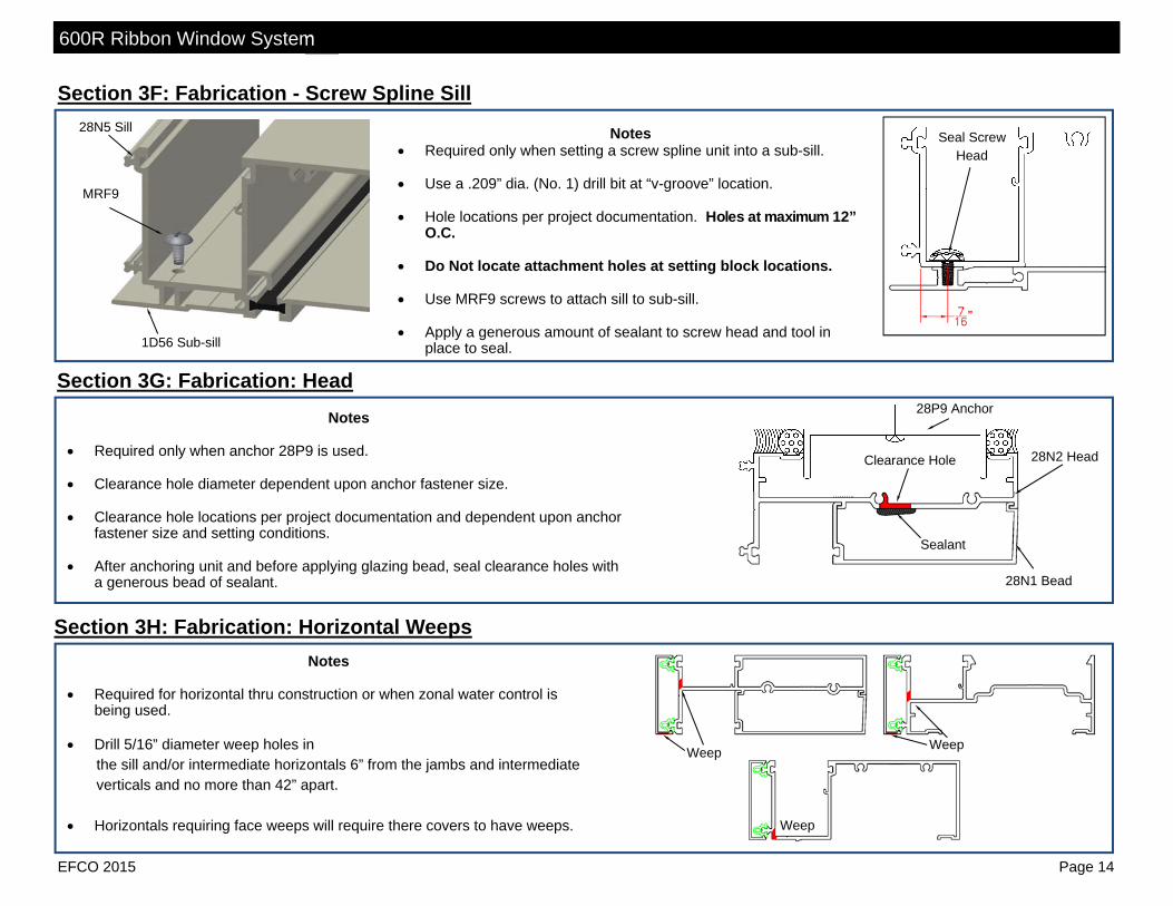
Required only when anchor 28P9 is used. Clearance hole diameter dependent upon anchor fastener size. Clearance hole locations per project documentation and dependent upon anchor
fastener size and setting conditions. After anchoring unit and before applying glazing bead, seal clearance holes with
a generous bead of sealant.
Notes Required only when setting a screw spline unit into a sub-sill. Use a .209” dia. (No. 1) drill bit at “v-groove” location. Hole locations per project documentation. Holes at maximum 12”
O.C. Do Not locate attachment holes at setting block locations. Use MRF9 screws to attach sill to sub-sill. Apply a generous amount of sealant to screw head and tool in
place to seal.
Seal Screw Head
28N5 Sill
1D56 Sub-sill
MRF9
28P9 Anchor
28N1 Bead
Sealant
28N2 Head Clearance Hole
Section 3H: Fabrication: Horizontal Weeps Notes
Required for horizontal thru construction or when zonal water control is
being used. Drill 5/16” diameter weep holes in the sill and/or intermediate horizontals 6” from the jambs and intermediate verticals and no more than 42” apart. Horizontals requiring face weeps will require there covers to have weeps.
Weep Weep
Weep

600R Ribbon Window System
EFCO 2015 Page 15
Section 4A: Unit Assembly - Screw Spline
Notes Apply a generous bead of sealant to the ends of
all horizontals to a minimum 1” back from the face of the horizontal glazing pocket as represented in figures 6 and 7 by the shaded areas.
Using (2) SPL3 fasteners per intersection attach horizontal framing members to a vertical framing member.
Due to the screw tensions required for correct installation, it will be necessary to ‘wax’ the frame assembly screws to prevent galling and breaking.
Clean off all excess sealant after assembly. Captured Intermediate vertical construction
shown, jambs and expansion mullions in captured and SSG units are assembled similarly.
Before snapping units together, run a bead of
sealant 6” up from the sill end of both snap legs on any covers used (i.e. 28N7).
Figure 7
Figure 6

600R Ribbon Window System
EFCO 2015 Page 16
Section 4B: Unit Assembly - Shear Block
Notes Using (2) STB5 fasteners per shear block install
them onto the vertical members. Due to the screw tensions required for correct
installation, it will be necessary to ‘wax’ the screws to prevent galling and breaking.
Apply a generous bead of sealant to the ends of all
horizontals to a minimum 1” back from the face of the horizontal glazing pocket as represented in figures 6 and 8 by the shaded areas.
Using (2) STB9 fasteners per shear block attach the
horizontal framing members. Clean off all excess sealant after assembly. Captured jamb construction shown, intermediate
vertical and expansion mullions in captured and SSG units are assembled similarly.
Figure 8

600R Ribbon Window System
EFCO 2015 Page 17
Section 4C: Unit Assembly - “B” Type
Notes Install any required shear blocks to the vertical framing
member per instructions shown in Section 4B. Due to the screw tensions required for correct installation, it
will be necessary to ‘wax’ the screws to prevent galling and breaking.
Apply a generous bead of sealant to the ends of all
horizontals and Verticals to a minimum 1” back from the face of the horizontal glazing pocket as represented in figures 6 and 9 by the shaded areas.
Using (2) SPL3 fasteners per intersection attach the vertical
to the head and sill framing members. Apply a generous bead of sealant to the sill end dam,
including across the top, as represented in figure 9. Using (2) STB9 fasteners attach an end dam to each end of
the sill framing member. Clean off all excess sealant after assembly. Install any intermediate horizontal members if require per
instructions shown in Section 4B. Captured jamb construction shown, intermediate verticals in
captured and SSG units are assembled similarly. Figure 9

600R Ribbon Window System
EFCO 2015 Page 18
Section 4D: Unit Assembly - SSG Expansion Mullion
Notes Assemble each unit as instructed in the either the Shear
Block Unit or Screw Spline Assembly Section. Take the SSG bridge part FVA5 and cut it into 2 equal
sections (see inset), removing approximately 1/8”. Apply a generous bead of sealant to the areas on each half bridge as shown in figure 10. If a fixture isn’t used to verify all parts are equal in size, keep halves of FVA5 together and use at one bridge point.
Due to the screw tensions required for correct installation, it will be necessary to ‘wax’ the screws to prevent galling and breaking.
Tool smooth any excess sealant so that water will flow
easily over the SSG bridge. SSG expansion mullion construction shown, intermediate
vertical SSG units are assembled using a full FVA5 bridge. Expansion mullions are required in elevations that are over
20’-0” to 25’-0” wide and can be used with both screw spline and shear block construction methods.
Do Not use expansion mullions at entrance jambs.
Locate the expansion mullion at the next vertical, still maintaining a distance between expansion mullions that is never more than 25’-0”.
Prior to anchoring the units of an expansion mullion, verify
that the expansion joint gap is maintained per project drawings.
Figure 10
FVA5
600R Ribbon Window System
EFCO 2015 Page 19
Section 5A: Door Frame Installation
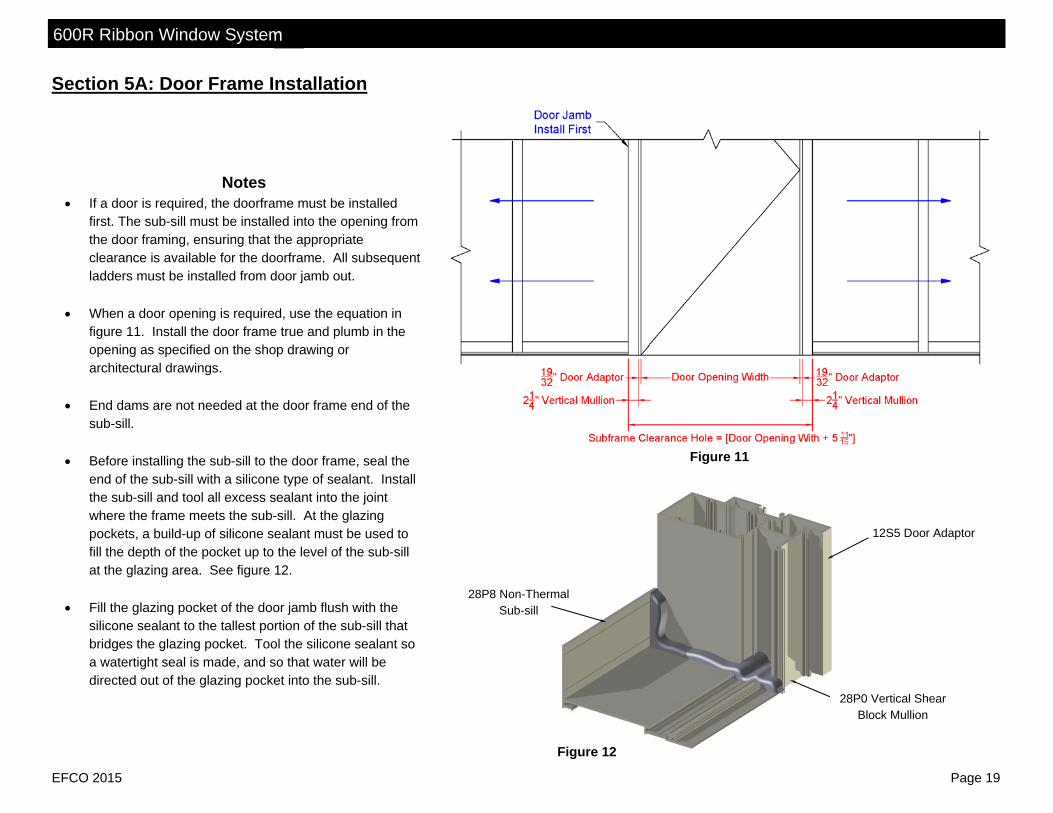
Notes If a door is required, the doorframe must be installed
first. The sub-sill must be installed into the opening from the door framing, ensuring that the appropriate clearance is available for the doorframe. All subsequent ladders must be installed from door jamb out.
When a door opening is required, use the equation in
figure 11. Install the door frame true and plumb in the opening as specified on the shop drawing or architectural drawings.
End dams are not needed at the door frame end of the
sub-sill. Before installing the sub-sill to the door frame, seal the
end of the sub-sill with a silicone type of sealant. Install the sub-sill and tool all excess sealant into the joint where the frame meets the sub-sill. At the glazing pockets, a build-up of silicone sealant must be used to fill the depth of the pocket up to the level of the sub-sill at the glazing area. See figure 12.
Fill the glazing pocket of the door jamb flush with the
silicone sealant to the tallest portion of the sub-sill that bridges the glazing pocket. Tool the silicone sealant so a watertight seal is made, and so that water will be directed out of the glazing pocket into the sub-sill.
Figure 11
Figure 12
12S5 Door Adaptor
28P0 Vertical Shear Block Mullion
28P8 Non-Thermal Sub-sill

600R Ribbon Window System
EFCO 2015 Page 20
Section 5B: Sub-sill Fabrication and Installation
Notes Measure the opening to determine the cut length of the sub-sill. Subtract 1/4” for the end dam and fastener head from the rough opening for each end.
Cut the sub-sill to the determined length. (Cut Length = Rough Opening - 1/2”) The end dams shall be attached to the sub-sill with 2 - SPZ1 fasteners per end. Seal the end of the sub-sill with silicone sealant before attaching the
end dam to the sub-sill. Tool the sealant at the interior joint of the end dam to ensure a good watertight seal. See figure 13 below. If end dams are not required, ensure the sub-sill is tight against the condition and seal the joint between the sub-sill and condition similar to figure 13.
Apply sealant to the top of the thermal cavity across the entire sub-sill and tool smooth. Using drill jig DJ65 drill 5/16” diameter weep holes in the sub-sill 6” from the jambs and no more than 42” apart. See figure 14. Weep baffles are cut from part HCW6. One part HCW6 will produce 4 baffles when cut per figure 15. Locate them at the weep holes per figure 14. Seal the sub-sill to the condition per shop drawings. Locate sub-sill anchors per shop drawing detail based
off of actual job conditions. As a general recommendation anchor 6” from jambs and corners and 16” on center between. Seal all anchor heads with a silicone type of sealant.
FVA1
Figure 13
28P8 Non-Thermal Sub-sill 1D56 Thermal
Sub-sill
SPZ1 Sealant over Strut
Figure 15 Figure 14
Weep HCW6 Baffle DJ65

600R Ribbon Window System
EFCO 2015 Page 21
Section 5C: Splices
Splice Notes Maximum length between splices is 20’ to 25’. Splice locations should be a
minimum of 8” from vertical mullion center line. When a splice is required, cut frame members to allow for a 1/4” gap splice
joint.
Sub-sill Splice Notes Apply silicone type sealant to both ends and fill the void between them as
shown in figure 16. Use a silicone type of sealant and a strip of WM01 bond breaker tape at
approximately 1-7/8” wide to create the splice material on the top of the sub-sill. Ensure that the bond breaker tape is centered over the 1/4” gap and then set the tape into the sealant. Tool the sealant over the bond breaker tape to create a watertight seal.
After the splice has been installed, apply a cosmetic seal to the interior gap,
vertically up the sub-sill splice.
Head Splice Notes Prior to setting the head, place silicone type of sealant to both sides of the
splice joint. Attach one side of the splice to the frame using a #STB9 screw. (see figure 17)
Slide next section of head over splice, leave a 1/4” joint and set in place. Using WM01 bond breaker tape, create a splice at the exterior glazing leg.
Ensure that the bond breaker tape is centered over the 1/4” gap and then set the tape into the sealant. Tool the sealant over the bond breaker tape to create a watertight seal. (see figure 17 for location)
Seal over gaps at splice joint.
Figure 16
28P8 Non-thermal Sub-sill
Fill void between sub-sills
Figure 17
28N2 Head
FVA9 Head Splice
STB9 Splice Attachment Screw
Sealant for Bond Breaker Tape Splice

600R Ribbon Window System
EFCO 2015 Page 22
Section 5C: Splices Sill Splice Notes
Prior to setting the sill, place silicone type of sealant on both sides of the splice joint. Attach one side of the splice to the frame using a STB9 screw. (see figure 18)
Slide next section of sill over splice, leave a 1/4” joint. Using WM01 bond breaker tape, create a splice from interior glazing leg to
the interior leg. Ensure that the bond breaker tape is centered over the 1/4” gap and then set the tape into the sealant. Tool the sealant over the bond breaker tape to create a watertight seal. See figure 18.
Set, anchor, and seal over gaps at splice.
Section 5D: Sill Sealing Notes
Apply a silicone type sealant to the locations shown in figure 19. See project specific documentation to see which sill style will be used.
A generous amount of sealant is required
to seal required joints. After installing the ladder for sub-sill type
installations or sill for “B” type installations, anchor the frame member then clean off excess sealant from any exposed areas.
Do Not allow sealant to skim over
before placing the framing members. If sealant does cure it will interfere with the sills installation into its anchoring system. Figure 19
28N5 Sill
Sealant
28P5 Sill Lug
WW78
Sealant
28P8 or 1D56 Sub-sill
Sealant
28N5 Sill
28P6 Sill Anchor
Figure 18 28N5 Sill
FVB1 Sill Splice STB9 Splice
Attachment Screw
Sealant for Bond Breaker Tape Splice

600R Ribbon Window System
EFCO 2015 Page 23
Section 5D: Installation - Mullion End Caps
Notes Type “A” Installation - captured: After framing members are installed into
the opening, apply silicone type sealant to one side of a FVB2 mullion end cap and slide it over the vertical mullion end. See figure 21. Shear block and screw-spline verticals and jambs are all similar.
Type “A” Installation - SSG: After framing members are installed into the
opening install the FVA5 bridge at the vertical mullion head per instructions. Then apply silicone type sealant to one side of a FVB2 mullion end cap and slide it over the vertical mullion end. See figure 20.
Expansion Mullion: Before installing either unit into the opening apply
silicone type sealant to the edges of HH66 and WNC4 mullion plugs. Push them into the top end of there applicable vertical so that the top of the plug is flush with the end of the expansion mullion vertical. See figure 22. Then install units into the opening per instructions.
WNC4 Plug
Figure 21
FVB2
Seal all 4 sides Figure 22
HH66 Plug
FVB2
Seal all 4 sides
Figure 20 FVA5 SSG
Bridge

600R Ribbon Window System
EFCO 2015 Page 24
Section 5D: Installation - Vertical Mullion Seal
28P9 Head Anchor
Figure 24 28N2
Figure 25 Figure 26
Bond Breaker Tape
28P8
28N8
A
Notes When the unit is installed and anchored, begin placing caulk backer
rope into the gap between the perimeter and the frame. See figure’s 24, 25, and 26.
If you are using 28P9 head anchors, use bond breaker tape on the
interior leg of the anchor as shown in figure 24. Apply a generous amount of silicone type sealant to the gap
between the frame and rough opening. Tool off all excess sealant to ensure a good seal and to achieve an
appropriate appearance. Be careful to not get sealant around the cover nubs indicated by the circled areas marked “A” in figures 24 and 26. Excess sealant in this area may interfere with the application of the cover.
A
Notes Prior to installing a two-piece intermediate vertical mullion, apply
silicone type sealant to the vertical mullion in the location shown in figure 23 (a) at the interior joints only. Apply the sealant as indicated 6-8 inches up from the bottom of the vertical.
Apply enough sealant so when the filler or opposite mullion half is
installed, it will create a seal. Wipe of the excess sealant from the exposed surfaces. See figure 23 (b) and (c).
This sealant practice should be followed on all variations of vertical
mullions, including the examples shown in figure 23.
SEAL
SNAP
CLEAN
Section 5D: Installation - Perimeter Seal
15D7
15B7
Figure 23
15U6
15U9
SEAL
SEAL SEAL
28N7
28P1
(a)
(b)
(c)

600R Ribbon Window System
EFCO 2015 Page 25
Section 6: Glazing – Setting Block Identification
Notes: Figure 27 shows setting blocks for 1” glazing. For intermediate horizontals 28N3 and 28N4 use setting block HEP3 for
1/2” glazing and setting block HN61 for 1/4” glazing. For sill profiles, 28N5, 28N8, and 28N6 when 1/4” or 1/2” glazing
adaptors are required, field notch the glazing adaptor at the setting block locations. See figure 27 for notching needed.
Customer / Installer Note: EFCO setting blocks are typically 4” in length. If the glazing infill is “NOT BY EFCO” and glazing sizes are larger than 40 square feet, Then the glazing details must be reviewed by the glazing Manufacturer for proper setting block size.
Figure 27
28N3
28N4
28N1
28N1
28N6
28N5
28N8
Adaptor Notch
HN60
HN60
HNA4
HN68
HN68
Section 6: Glazing – Glass Pocket Identification
Notes: Ensure that each vertical D.L.O. has at least one
DEEP glass pocket on either side. It is necessary for the glazing installation that a deep pocket be used to load the glazing units.
The details in figure 28 show a circled “D” in the
deep pockets and a circled “S” for shallow pockets.
28N8 28P0
Figure 28
28P1
28P2 28P3
28S1

600R Ribbon Window System
EFCO 2015 Page 26
Section 6: Glazing – Glass Size Formulas
Notes: For captured glazing the glass bite is 1/2”. For structural glazed vertical mullions the glass bite is 7/8”.
Formulas: From Captured Mullion to Captured Mullion: Glass Size = D.L.O. + 1” From Captured Mullion to SSG Mullion: Glass Size = D.L.O. + 1 3/8” From SSG Mullion to SSG Mullion: Glass Size = D.L.O. + 1 3/4” ALL vertical glass sizing: Glass Size = D.L.O. + 1”
Figure 29
28N8
GLASS
Section 6: Glazing – Water Deflectors Notes:
Install the HWD1 water deflector at the ends of all of the intermediate horizontals only. It is not required at the heads or sills.
Use a silicone type sealant to adhere the HWD1 onto the
intermediate horizontal. Make certain that the water deflector sits flush with the top of the intermediate horizontals glazing pocket. See figure 30.
Add a generous amount of sealant to cover the gap from the
water deflector to interior glazing leg. See figure 30. Tool smooth any excess sealant so that water will flow
easily over the water deflector.
Typical Vertical
Figure 30
This end extends into the vertical glazing pocket and over
the lower glass unit’s corner.
Typical Horizontal
HWD1 Water Deflector
GLASS
15U3 28P2
28P3

600R Ribbon Window System
EFCO 2015 Page 27
Section 6: Glazing – Installing Glass Setting Blocks Notes:
Glass setting blocks are designed to be used at 1/4 points standardly or 1/8 points for special dead load applications. Please consult the engineer of record for placement for dead loading.
See figure 27 to identify the setting block required for your condition. It may be necessary to apply a small amount of sealant to the bottom of
the setting block to enable it to remain in its intended position. Refer to figure 31 to verify 1/4 point (on left side) and 1/8 point (on right
side) blocking. Figure 31
Section 6: Glazing – Pre-Set Gasket Installation Remove the glazing gasket from the reel, and allow it to relax and shrink. Apply silicone type sealant into the raceways a minimum of 2” in each direction from the
corners of the D.L.O.. See Figure 32. Once the gasket has relaxed, cut and install into position. Cut the vertical gaskets at
vertical D.L.O. plus 1/2”. Place the gasket in the raceway starting at the center of the D.L.O.. Then set each end of the gasket into the raceway at the D.L.O. and then crowd the remaining gasket into the raceway.
Cut the horizontal gaskets:
Captured Vertical to Captured Vertical = D.L.O. plus 1/2” Captured Vertical to SSG Vertical = D.L.O. plus 1-5/8” SSG Vertical to SSG Vertical = D.L.O. plus 2-3/4”
Insert into the raceway in the center of the D.L.O. then set captured vertical ends
butted up to vertical gasket and SSG vertical ends to center of SSG bridge, then crowd the remaining gasket into the raceway. D.L.O.’s of less then 24” may require gasket length be shortened by 1/4” to be able to install.
Seal all gasket at captured corners. (see inset)
Sealant
Figure 32
Note: Sealant should only be applied immediately before applying gaskets
and setting glass. HWD1 Water
Deflector

600R Ribbon Window System
EFCO 2015 Page 28
Section 6: Glazing – Glazing Installation Captured Vertical Mullions
Note: Clean all glazing pockets prior to glazing. This is necessary to avoid clogging the weep system as well as to prevent staining of the exterior metal and glass surfaces.
Step 1- Install Glazing Materials Using suction cups, gently insert a glass edge (or other glazing infill) into the deep pocket of the vertical mullion. (Figure 33 Position A) Swing the opposite edge of the glazing in plane with the shallow pocket of the adjacent vertical mullion, and lower the glazing onto the setting
blocks. (Figure 33 Position B and C) Position the glazing in the center of the opening maintain a 1/2” glass bite around the entire perimeter. (Figure 33 Position C) Lift the infill slightly off the setting blocks, and press the glass firmly against the exterior glazing gaskets at the sill.
Step 2- Install Temporary Retainer Gaskets Use 2” long pieces of the interior wedge gasket to temporarily compress and hold the glazing into the glazing pocket of the verticals. The
gaskets should be placed at the corners of the glazing and then periodically up the vertical. On the exterior side, remove any excess sealant that may ooze out of the corners where the gaskets were butt sealed.
Go to Step 3
Figure 33

600R Ribbon Window System
EFCO 2015 Page 29
Section 6: Glazing – Glazing Installation SSG Vertical Mullions
Clean all glazing pockets prior to glazing. This is necessary to avoid clogging the weep system as well as to prevent staining of the exterior metal and glass surfaces.
Step 1- Install Glazing Materials Using suction cups, gently insert a glass edge (or other glazing infill) into the deep pocket of the vertical mullion. (see figure 34, position A) Swing the opposite edge of the glazing in plane with the SSG pocket of the adjacent vertical mullion, and lower the glazing onto the setting
blocks. (figure 34, position B and C) Position the glazing in the opening maintaining a 1/2” glass bite at captured frame members and 7/8” glass bite at structural glazed vertical
members. (figure 33, position C) Lift the infill slightly off the setting blocks, and press the glass firmly against the exterior glazing gaskets at the sill.
Step 2- Install Temporary Retainer Gaskets Use 2” long pieces of the interior wedge gasket to temporarily compress and hold the glazing into the glazing pocket of the captured frame
members. The gaskets should be placed at the corners of the glazing and then periodically along D.L.O.. Cut WSA1 spacer the SSG vertical D.L.O. plus 1/2”. Insert the spacer into the area shown in figure 35 leaving 1/2” of space between the
spacer and the side of the vertical. Place the temporary glazing clip HGR1 in the structural mullion race and rotate to hold glass at the structural mullion. Place multiple clips along
the vertical. See figure 35. If glazing to an expansion SSG vertical, drill .180 diameter holes and screw apply a FC76 clip as temporary glazing as shown in figure 35 at
quarter points of vertical. DO NOT over tighten screw. Over tightening screw may result in glass breakage or deformation.
Figure 34 Figure 35
WSA1 SSG Spacer
HGR1 SSG Glazing Clip
SDR4 WEP0 Gasket
FC76
600R Ribbon Window System
EFCO 2015 Page 30
Section 6: Glazing – Glazing Installation
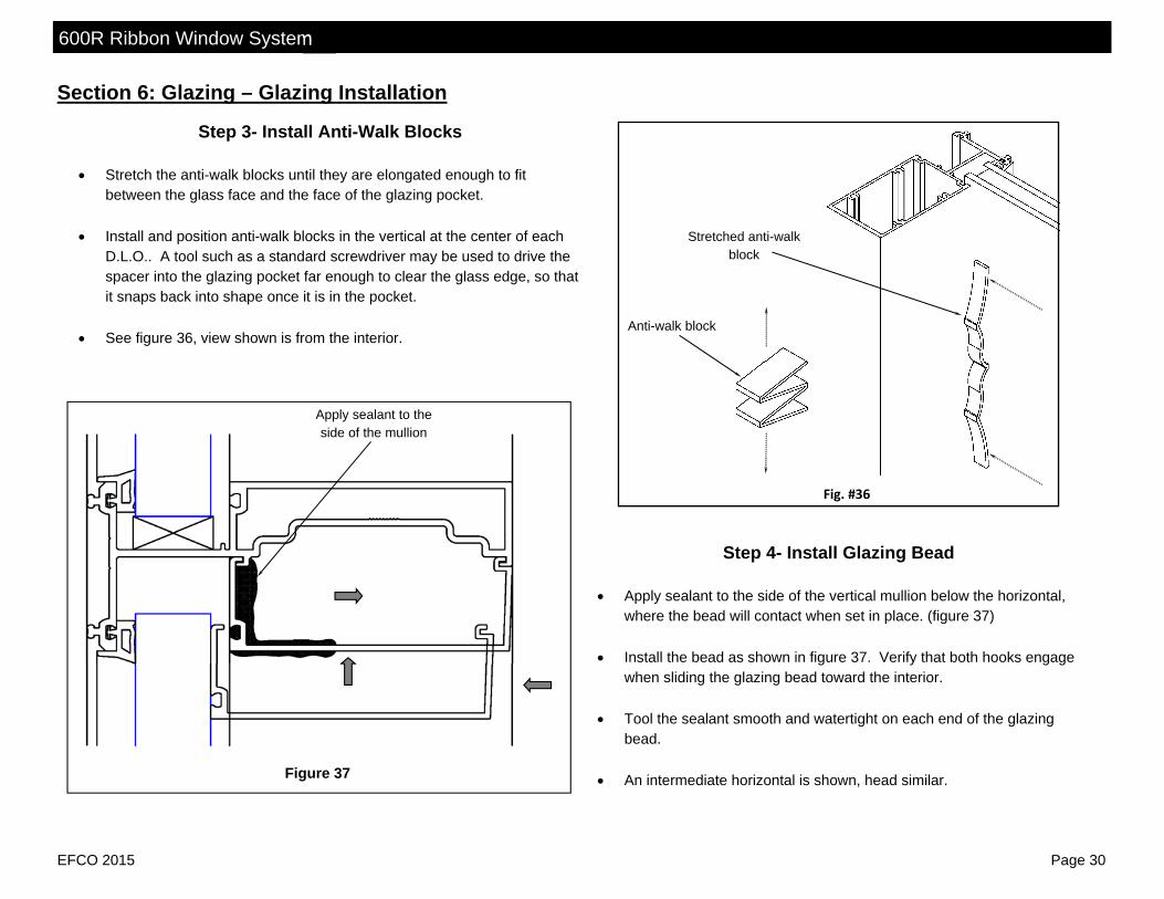
Step 3- Install Anti-Walk Blocks
Stretch the anti-walk blocks until they are elongated enough to fit between the glass face and the face of the glazing pocket.
Install and position anti-walk blocks in the vertical at the center of each
D.L.O.. A tool such as a standard screwdriver may be used to drive the spacer into the glazing pocket far enough to clear the glass edge, so that it snaps back into shape once it is in the pocket.
See figure 36, view shown is from the interior.
Fig. #36
Anti-walk block
Stretched anti-walk block
Step 4- Install Glazing Bead
Apply sealant to the side of the vertical mullion below the horizontal, where the bead will contact when set in place. (figure 37)
Install the bead as shown in figure 37. Verify that both hooks engage
when sliding the glazing bead toward the interior. Tool the sealant smooth and watertight on each end of the glazing
bead. An intermediate horizontal is shown, head similar.
Apply sealant to the side of the mullion
Figure 37

600R Ribbon Window System
EFCO 2015 Page 31
Section 6: Glazing – Glazing Installation
Step 5- Install Interior Drive-In Gasket Remove the drive-in wedge gasket material from the reel and allow the gasket to
relax and shrink. Remove any temporary retainer gaskets previously applied, from the opening at
hand. Starting with the vertical gaskets, cut them D.L.O. plus 1 3/4”. Apply the gasket by
driving in the wedge gasket, starting at the center of the D.L.O. and then crowd in the excess at the ends.
Care should be taken not to stretch the gasket when installing. The vertical gasket
should run through and extend past the horizontal gaskets, once they are installed. Cut the horizontal drive-in gaskets at D.L.O. plus 1/2”. Apply the gasket by driving
in the wedge gasket, starting at the center of the D.L.O. and then crowd in the excess at the ends.
Before driving in the end of the gasket , place sealant on the end, see figure 38),
thus sealing the butt joint between the vertical and horizontal drive-in glazing wedge when it is installed.
Step 6– Apply Interior SSG Sealant Mask off the glass and vertical SSG Mullion as shown in figure 39 with masking
tape to minimize cleanup. Apply silicone type sealant between the SSG vertical and glass. Tool the sealant, remove masking before the sealant cures. Clean any excess sealant.
Apply sealant to the side of the vertical gasket
Figure 38
Apply sealant to the of the gasket
Applied masking
Figure 39

600R Ribbon Window System
EFCO 2015 Page 32
Section 6: Glazing – Glazing Installation
Step 7 - Fill Structural Glazing Gap After the interior sealant has cured, typically an overnight setup is
required, mask off the glass edges with masking tape to minimize cleanup and to provide a professional appearance.
Remove the temporary SSG glazing clips. Fill the screw holes made on the expansion mullion to hold the
retainer clips with sealant. Proceed with filling the void between the glass units at the exterior
with backer rod and structural silicone sealant to fill the void out to the exterior gasket of the horizontal members.
At the horizontal members, fill the cavity with sealant to fill the void
out to the gasket. Tool the sealant using a putty knife across the glass edges. Remove
excess silicone from the glass surface by removing the masking tape before a skin begins to form. Any excess sealant on the glass units can be removed with a razor blade. (see figure 40)
Structural Silicone Structural Silicone
S.S.G. Expansion
Vertical
Figure 40
S.S.G. Vertical

600R Ribbon Window System
EFCO 2015 Page 33
Section 6: Glazing – Re-glazing Instructions
Notes: Re-glaze from Interior:
Remove glazing bead , gaskets, and broken glass. Replace the broken glass with a new lite of same size. Re-glaze the lite of glass using the previous instructions found in Section: 6
Glazing. Re-glaze from the Exterior:
Carefully remove the face cover from the horizontal member above the affected lite.
Remove the glass, and glazing material from opening to be re-glazed. Cut off the bottom exterior leg of the horizontal or head member above the
opening. Cut at the “V-groove” in the face of the leg. (see figure 41) Note: Be careful not to damage the adjoining vertical face covers when
making cut.
Groove
Figure 41
Remove shaded area
Remove shaded area
Groove
Figure 42
STB9
STB9
WEP2
WEP2
WEC5
WEC5
Sealant
Sealant
Drill .180” diameter holes on the re-glaze bead at the “V-groove”, 1-1/2” from each end and then at a maximum 12” O.C. in between.
Install new pre-set glazing into the interior glazing reglets following previous glazing instructions for sealing ends of gasket.
Glaze new lite into opening. Hold glass in place with temporary drive-in gasket wedge clips on the verticals.
Run a continuous bead of sealant along face of horizontal to take re-glaze bead. (see figure 42)
Screw apply the re-glaze bead using STB9 screws. Seal heads of all fasteners. (see figure 42)
Note: The re-glaze bead must be properly aligned with the head or horizontal in order to have the face cover snap correctly.
Install new exterior drive-in glazing wedge gasket and seal all corners of gasket.
Replace the horizontal face cover.

600R Ribbon Window System
EFCO 2015 Page 34
Section 7: Face Covers Notes:
Isolator Clips: To install an isolator clip requires the installer to engage the clip over one half of the
isolator clip nub and then by hand “snap” it over the nub completely. Place 2 clips at each end of all pieces of face cover. Do not place clips in area of
intersecting framing member. (see detail “A” figure 43) Place 2 clips staggered between 5” to 8” across all intermediate intersections. (see
detail “B” figure 43) Alternate clips on the two clip races on the front of all framing members at a minimum
of 12” O.C. between all ends and intersections. Cover Clip:
Attach a cover clip on all vertical covers at an intersecting horizontal member. Locate the clip as close to the vertical mid-span as possible. (see detail “B” figure 43)
Apply a generous amount of sealant to the screw head. (see figure 45) Face Covers:
Install the face covers on the framing members that run through, first. Start installation at on end and work to other end. Place face cover onto clips and “snap” onto the system. It should take very little force
to perform this, however, it may require the usage of a rubber mallet and a clean piece of scrap lumber to snap the cover on. (see figure 44)
Drill a hole and install .156” x .625” roll pin into cover clip prior to installing the intersecting horizontal covers. (see figure 45)
Rubber Mallet
Detail “A”
Figure 43
Detail “B”
Figure 44
FVA6
HL92
STB9
Figure 45