609-tbae-01-english st drawing sheet · 2015-05-04 · design standards engineer date ... 5/8"...
TRANSCRIPT
E 805-SDAC-01
INDIANA DEPARTMENT OF TRANSPORTATION
STANDARD DRAWING NO.
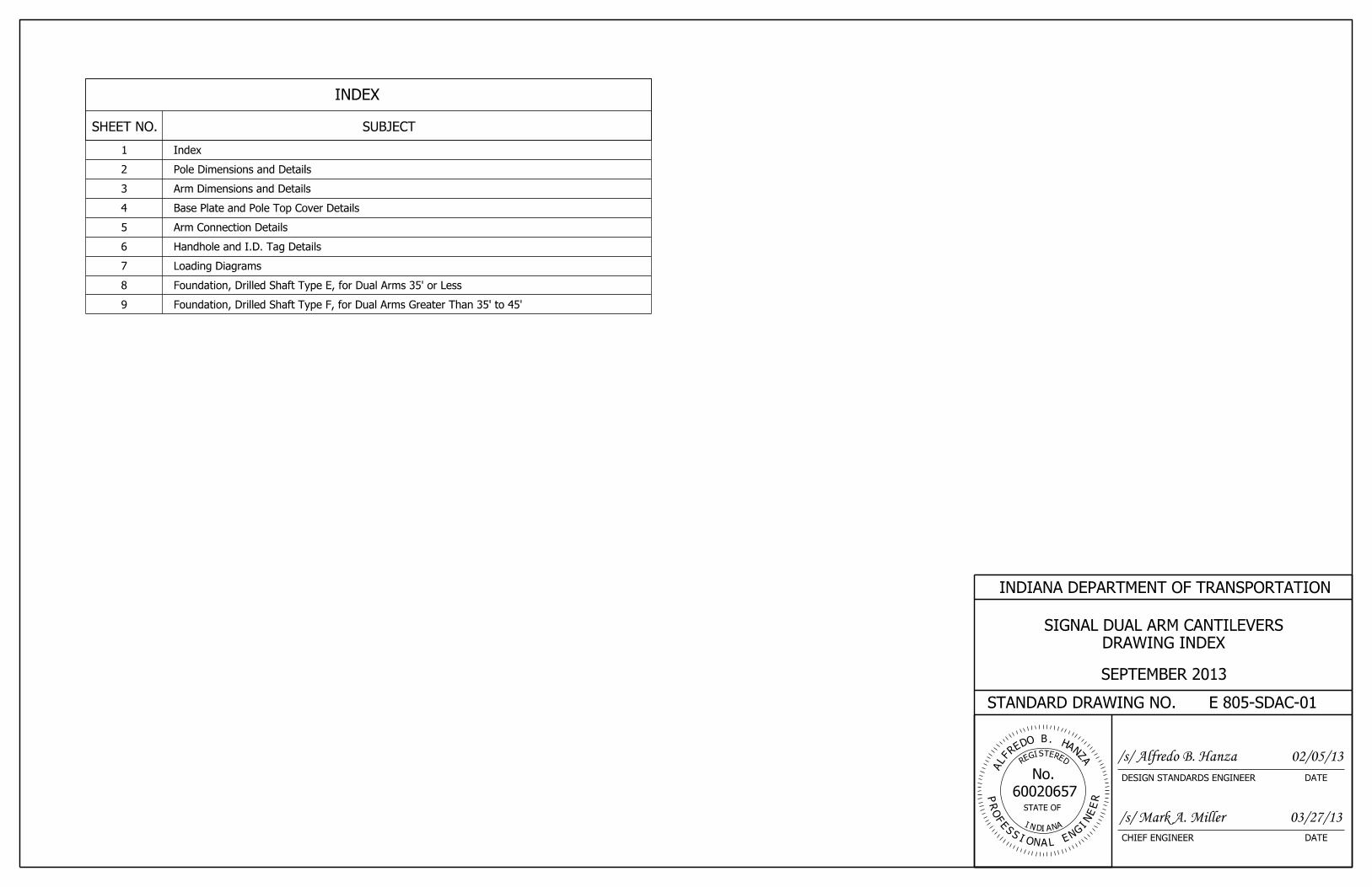
SHEET NO. SUBJECT
INDEX
1 Index
SEPTEMBER 2013
DRAWING INDEX
SIGNAL DUAL ARM CANTILEVERS
2 Pole Dimensions and Details
3 Arm Dimensions and Details
4 Base Plate and Pole Top Cover Details
5 Arm Connection Details
7 Loading Diagrams
8 Foundation, Drilled Shaft Type E, for Dual Arms 35’ or Less
9 Foundation, Drilled Shaft Type F, for Dual Arms Greater Than 35’ to 45’
6 Handhole and I.D. Tag Details
RET
60020657
EDS
R
ER
IEG
A
AH.
AZ
NB
R
FL
ODE
N
P
NI
FO
R
N A
No.
STATE OF
ID A
E
ENA
E
G
I
LIO
S
NS
DATECHIEF ENGINEER
DATEDESIGN STANDARDS ENGINEER
02/05/13/s/ Alfredo B. Hanza
/s/ Mark A. Miller 03/27/13

5/16" 5/16"
2"
2’-4"
2’-0"
1’-6"
1’-4"
45’ arm
s
35’ arm
s
1’-6"
L
Sig
nal
Arm M
ounting H
eig
ht (2
2’-0"
Max.)
2"
Drilled Shaft Foundation
Arm
Upper Signal
Top Cover
Lower Signal Arm
Handhole B
Pole
Handhole A
ELEVATION
See Detail A this sheet.
Weld pole to base plate.
I.D. Tag 2
2
1
2
4
7 Base Plate
8
(Typ.)
5/16" x 2" Backing Ring
DETAIL A
POLE/BASE PLATE WELD
Base Plate
Pole Outside Face
1/8
UT 25%M
3/16
45°1/4
Weld
Seal
thickness
Wall
TUBULAR SHAPE
OCTAGON AND CIRCULAR
Dia
meter
(IN.)
DIAMETER
BASE
(IN.)
THICKNESS
WALL
15’ to 35’ 18 5/16
24 5/16> 35’ to 45’
(FT)
L
ARM LENGTHS
CANTILEVER
POLE DIMENSIONSE 805-SDAC-02
INDIANA DEPARTMENT OF TRANSPORTATION
STANDARD DRAWING NO.
POLE DIMENSIONS AND DETAILS
SIGNAL DUAL ARM CANTILEVERS
SEPTEMBER 2013
5
6
6
See Standard Drawing E 805-SDAC-05 for arm connection details.8
See Standard Drawing E 805-SDAC-04 for base plate details.7
0.14 in./ft taper. All member diameters shown are outside diameter.
Pole and arms may be octagonal or circular shaped and shall have a 6
ultransonically tested (UT).
A minimum of 25% of the pole to base plate welds shall be 5
See Standard Drawings E 805-SDAC-08 and -09 for foundation details.4
details.
See Standard Drawings E 805-SGGR-01 through -03 for grounding 3.
details.
See Standard Drawing E 805-SDAC-06 for handhole and I.D. tag 2
Cantilever arms can be positioned at 20° to 180° to each other.
This structure is a dual arm cantilever design for traffic signals. 1
NOTES:
RET
60020657
EDS
R
ER
IEG
A
AH.
AZ
NB
R
FL
ODE
N
P
NI
FO
R
N A
No.
STATE OF
ID A
E
ENA
E
G
I
LIO
S
NS
DATECHIEF ENGINEER
DATEDESIGN STANDARDS ENGINEER
02/05/13/s/ Alfredo B. Hanza
/s/ Mark A. Miller 03/27/13

Splice
See Detail B.
Optional Splice
Handhole B
=3R
ELEVATION
1’-0" 11’-0" 12’-0"
30’-0" Min.
Arm Length, L
6
6
1
4
2
2
3 Arm Rise, R
End Cap
Lower Signal Arm
Upper Signal Arm
Inlet A Inlet BInlet C
Top Cover
for arm connection details. (Typ.)
See Standard Drawing E 805-SDAC-05
60°
SECTION A-A
TYPICAL SEAM WELD
DETAIL B
A
A
@ Splice
End S
ect.
2R
5/8" Through-Bolt
Splice
and Lock Nut
with Curved Washers
5/8" Through-Bolt Drilled Holes for 5/8" Bolt
Thickness 3/16" and with
with Minimum Wall
End Section Extension
5/8" Bolt
Field-Drilled Holes and
Base Section with
SIGNAL DUAL ARM CANTILEVER DATA
(IN.)
THICKNESS
ARM WALL
INLETS
CABLE
(IN.)
AT POLE
DIAMETER
ARM
(FT.)
L
LENGTH
ARM
15 14 5/16 7 1/2 A, B
20 14 5/16 A, B
25 14 5/16 12 1/2 A, B
30 14 5/16 A, B
35 14 5/16 17 1/2
40 17 5/16
45 17 5/16 22 1/2
10
15
20
A, B, C
A, B, C
A, B, C
(IN.)
R
ARM RISE
E 805-SDAC-03
INDIANA DEPARTMENT OF TRANSPORTATION
STANDARD DRAWING NO.
SEPTEMBER 2013
ARM DIMENSIONS AND DETAILS
SIGNAL DUAL ARM CANTILEVERS
6
3
The inlet diameter shall be 1 3/4" with rubber grommet (typ.).
Number of cable inlets depends on arm L (see table on this sheet). 7.
seam welds shall be 100% ultrasonically tested.
for the arms, and on the side of pole as shown. All pole and arm
If seam welds are used, the weld location shall be along the bottom 6
See Standard Drawing E 805-SDAC-07 for loading diagrams.5.
See Standard Drawing E 805-SDAC-06 for handhole B details.4
on the arm.
Arm rise is measured in the undeflected position without vertical loads 3
less than 3 times the inside radius ofthe end section).
greater. Field assembly to achieve a snug tight joint (min. overlap not
extension section of the arm shall have a wall thickness of 3/16" or
splice shall be located a minimum of 30’ from the pole. The end
Optional splices can be used for greater than 40’ mast arms. The 2
The dimensions and details shall be as shown on this drawing.
Upper signal arm can be oriented 20° to 180° from lower signal arm. 1
NOTES:
RET
60020657
EDS
R
ER
IEG
A
AH.
AZ
NB
R
FL
ODE
N
P
NI
FO
R
N A
No.
STATE OF
ID A
E
ENA
E
G
I
LIO
S
NS
DATECHIEF ENGINEER
DATEDESIGN STANDARDS ENGINEER
02/05/13/s/ Alfredo B. Hanza
/s/ Mark A. Miller 03/27/13

B B
PLAN
BASE PLATE
SECTION B-B
A
B
A
D
1
E
BASE PLATE DATA
(IN.)
E
DIAMETER
BOLT HOLE
(IN.)
D
THICKNESS
PLATE
(IN.)
C
CIRCLE
ANCHOR BOLTS
(IN. X IN.)
A X B
DIMENSIONS
PLATE
(IN.)
DIAMETER
POLE
18 26 x 26 25 2 1/4 2 9/16
24 30 x 30 31 2 1/2 2 13/16
SECTION C-C
Column + 1 3/8"
Outside Dia. of
C C
Washer (Typ.)
Nuts and Curved
1/2" Dia. Bolt w/Hex
in 2 places
Tack weld nut
Cover Plate
1/8" Top
of column + 1/8".
Bend to outside dia.
Plate 3/8" x 3"
3/16
3"
1/8
"
Handhole B 3
21’-4" or 1’-6"
See detail this sheet.
J-Hook
TOP COVER - STEEL COLUMN
PLAN 4"
CABLE J-HOOK
3"
Max.
2"
Cap Not Shown
Top of End-Support Column,
Spot Weld
3/8" J-Hook
E 805-SDAC-04
INDIANA DEPARTMENT OF TRANSPORTATION
STANDARD DRAWING NO.
SEPTEMBER 2013
BASE PLATE AND POLE TOP COVER DETAILS
SIGNAL DUAL ARM CANTILEVERS
See Standard Drawing E 805-SDAC-06 for handhole details.3
See Standard Drawing E 805-SDAC-02 for handhole locations.2
Cutting or trimming of the washers will not be allowed.
Anchor bolt circle shall allow clearance for the anchor bolt washers. 1
NOTES:
RET
60020657
EDS
R
ER
IEG
A
AH.
AZ
NB
R
FL
ODE
N
P
NI
FO
R
N A
No.
STATE OF
ID A
E
ENA
E
G
I
LIO
S
NS
DATECHIEF ENGINEER
DATEDESIGN STANDARDS ENGINEER
02/05/13/s/ Alfredo B. Hanza
/s/ Mark A. Miller 03/27/13
4" Radius
Diameter
Outside Pole
Rubber Grommet
12" Ø Hole with
C
1 1/2
"

ELEVATION OF GUSSET PLATE
TOP OF GUSSET PLATE
1/4
1 1/2"
1/4
1/4
1/4Ring Stiffener
Gusset Plate
Ring Stiffener
Ring Stiffener
Gusset Plate
Ring Stiffener
Typ.D
D
EE
SIGNAL ARM CONNECTION DETAIL
SECTION D-D ELEVATION
SECTION E-E
TABLE OF PLATES AND BOLTS FOR SIGNAL DUAL ARM CANTILEVER
Weld
Seal
2
Typ.
Handhole B
Flange Plate
X°
X°1/4
1/4
3/8
1/2
1 1/2
1/8
(See Table)
(See T
able)
(See T
able)
(See Table)
(See Table)
(See T
able)
Plus 1 1/2"
Rs = Pole Radius
(IN.)
A X B
FLANGE PLATE
(IN. X IN.)
C X D
BOLT PATTERN
(FT)
LENGTH
ARM
(IN.)
t
THICKNESS
PLATE
FLANGE
(IN.)
DIAMETER
BOLT
(IN.)
LENGTH
BOLT
1 1/4
1 1/2
15 to 35 22 x 22 17 1/2 x 17 1/2 5
26 x 26 21 1/2 x 21 1/2 2 6
B
AA
D
C
> 35 to 45
1/4
2 - Flat Washers
with 1 - Hex Nut &
4 - Bolts Each
Bending Radius Rs
Ring Stiffener With
in Pole and Flanges
Grommet for Cable Access
3" Ø Hole With Rubber
Flange Plate
Ring Stiffener (Typ.)
Max.
3"
Rotation Point
Backup Ring
Signal Arm
(IN.)
W
THICKNESS
& GUSSET PLATE
RING STIFFENER
(5/16 + 0.44) x 5/16
45°
1/4
< X°
< X°
5/1
6"
5/1
6"
2"Arm tube
Ring
5/16" x 2" Backing
Face
Outside
A x B
Flange Plate
ARM WELD
DETAIL C
E 805-SDAC-05
SEPTEMBER 2013
E 805-SDAC-03.
Signal Dual Arm Cantilever Data table on Standard Drawing
rise and L is the arm length. Both R and L vary and are listed in the
angle X. The angle X is described as arc tan R/L, where R is the arm
The required signal arm rise shall be built into the gusset plate at the 2
See Standard Drawing E 805-SDAC-06 for Handhole B details.1.
NOTES:
ARM CONNECTION DETAILS
SIGNAL DUAL ARM CANTILEVERS
INDIANA DEPARTMENT OF TRANSPORTATION
STANDARD DRAWING NO.
RET
60020657
EDS
R
ER
IEG
A
AH.
AZ
NB
R
FL
ODE
N
P
NI
FO
R
N A
No.
STATE OF
ID A
E
ENA
E
G
I
LIO
S
NS
DATECHIEF ENGINEER
DATEDESIGN STANDARDS ENGINEER
02/05/13/s/ Alfredo B. Hanza
/s/ Mark A. Miller 03/27/13
Ring Stiffener
W, Thickness of
t
t
Gusset Plates
W, Thickness of
Ring Stiffener
W, Thickness of
See Detail C
1/8
t
Weld
Seal
2
2

Washer (Typ.)
1/2" SS Flat
Cap Screw with
1/2" x 1" SS Hex
AT HANDHOLE A
PARTIAL ELEVATION
E 805-SDAC-06
SEPTEMBER 2013
HANDHOLE AND I.D. TAG DETAILS
SIGNAL DUAL ARM CANTILEVERS
Fabrication Date _____, Pole Mounting Height _____
Contract #_____, Structure Type _____
Manufacturer _____, Drawing/Order #_____
stamped in 1/2" black letters:
I.D. tag is a 1/8" stainless steel plate with the following information 4
See Standard Drawing E 805-SDAC-02 for handhole locations.3.
3" plate (rolling direction vertical).
In lieu of fabricated handhole frame as shown, frame may be cut from 2
at all other locations.
Handhole A to be used at the base of the pole. Handhole B to be used 1.
NOTES:
INDIANA DEPARTMENT OF TRANSPORTATION
STANDARD DRAWING NO.
RET
60020657
EDS
R
ER
IEG
A
AH.
AZ
NB
R
FL
ODE
N
P
NI
FO
R
N A
No.
STATE OF
ID A
E
ENA
E
G
I
LIO
S
NS
DATECHIEF ENGINEER
DATEDESIGN STANDARDS ENGINEER
02/05/13/s/ Alfredo B. Hanza
/s/ Mark A. Miller 03/27/13
4
(Dimensions vary)
I.D. Tag
Pole
Grounding Clamp
Pole Dia.
Handhole A
SECTION ACROSS POLE
HANDHOLE B
HANDHOLE B
HANDHOLE A
FRAME DETAIL COVER
FRAME DETAIL COVER1" 6" 1"
1/4
Typ.
t
8"
7"
10"
7 1/2
"
1’-0"
7 1/2
"
8"
7"
(Typ.)
2
Bar Frame
1"X 3" Flat
1"
(Typ.)
8" x 12" x 3/16" Plate
Arm Axis
1/4
Typ.
t
6"
8"
2
Bar Frame
1"X 3" Flat
1" (Typ.)
6" x 8" x 3/16" Plate
1" 4" 1"
Arm Axis
1/2 "
1/2 "
t - 1/8
t - 1/8
2 1/2 "
R
1 1/2 "R
2 1/2 "
R
3" 3" 3"3"
6" 6"
1/2
"
1/2
"
1/2
"
3"
3"
SECTION ACROSS POLE
HANDHOLE A
Pole
Grounding Clamp
galvanizing
thread after
3/8" - 20 Chase
4 screws,
Drill and tap for
galvanizing
thread after
3/8" - 20 Chase
2 screws,
Drill and tap for
Holes
1/2" Ø
(Typ.)
Hole
1/2" Ø
(Typ.)
1 1/2 "R
1/2
"
Pole
4"
6"
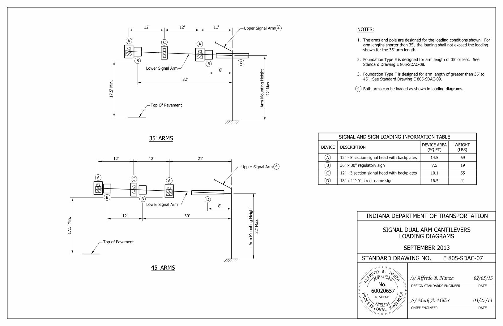
12’ 30’
45’ ARMS
12’ 12’ 21’
8’
22’
Max.
Arm M
ounting H
eig
ht
17.5’
Min.
Top of Pavement
Lower Signal Arm
Upper Signal Arm
35’ ARMS
8’
11’12’12’ Upper Signal Arm
17.5’
Min.
22’
Max.
Arm M
ounting H
eig
ht
SIGNAL AND SIGN LOADING INFORMATION TABLE
DEVICE DESCRIPTION(LBS)
WEIGHT
(SQ FT)
DEVICE AREA
12" - 5 section signal head with backplates 14.5 69A
B
C 12" - 3 section signal head with backplates
D
36" x 30" regulatory sign 7.5 19
10.1 55
18" x 11’-0" street name sign 16.5 41
E 805-SDAC-07
INDIANA DEPARTMENT OF TRANSPORTATION
STANDARD DRAWING NO.
SEPTEMBER 2013
LOADING DIAGRAMS
SIGNAL DUAL ARM CANTILEVERS
Both arms can be loaded as shown in loading diagrams.4
45’. See Standard Drawing E 805-SDAC-09.
Foundation Type F is designed for arm length of greater than 35’ to 3.
Standard Drawing E 805-SDAC-08.
Foundation Type E is designed for arm length of 35’ or less. See 2.
shown for the 35’ arm length.
arm lengths shorter than 35’, the loading shall not exceed the loading
The arms and pole are designed for the loading conditions shown. For 1.
NOTES:
RET
60020657
EDS
R
ER
IEG
A
AH.
AZ
NB
R
FL
ODE
N
P
NI
FO
R
N A
No.
STATE OF
ID A
E
ENA
E
G
I
LIO
S
NS
DATECHIEF ENGINEER
DATEDESIGN STANDARDS ENGINEER
02/05/13/s/ Alfredo B. Hanza
/s/ Mark A. Miller 03/27/13
Top Of Pavement
Lower Signal Arm
32’
4
4
A C A
A C A
BB D
B B D
1’-1"
1’-1"
Base Plate
Base Plate
2’-2"
6’-0"
2 1/4" Ø
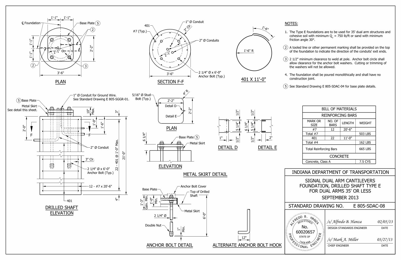
BILL OF MATERIALS
BARS
NO. OFLENGTH WEIGHT
CONCRETE
665 LBS
22
SIZE
MARK OR
11’-0"
162 LBSTotal #4
Total #7 503 LBS
#7 12 20’-6"
Concrete, Class A 7.5 CYS
401
REINFORCING BARS
Total Reinforcing Bars
PLAN
2" Ø Conduit
12 - #7 x 20’-6"
22 - 4
01 @ 1’-0"
Max.
21’-0"
2’-0"
4"
3"
3" Clr.
401
5
Base Plate See Standard Drawing E 805-SGGR-01.
1" Ø Conduit for Ground Wire.Max.
10"
ELEVATION
DRILLED SHAFT
See detail this sheet.
Metal Skirt
Anchor Bolt (Typ.)
2 1/4" Ø x 6’-0"
2’-1"
SECTION F-F
1" Ø Conduit
2" Ø Conduits
401
#7 (Typ.)
3’-6"Anchor Bolt (Typ.)
2 1/4" Ø x 6’-0"
DETAIL D DETAIL E
METAL SKIRT DETAIL
PLAN
ELEVATION
5
ANCHOR BOLT DETAIL ALTERNATE ANCHOR BOLT HOOK
12"
Min.
1"
Galv.
Min.
1’-3"
Min.
1’-0"
401 X 11’-0"
E 805-SDAC-08
INDIANA DEPARTMENT OF TRANSPORTATION
STANDARD DRAWING NO.
SEPTEMBER 2013
FOR DUAL ARMS 35’ OR LESS
FOUNDATION, DRILLED SHAFT TYPE E
SIGNAL DUAL ARM CANTILEVERS
See Standard Drawing E 805-SDAC-04 for base plate details.5
construction joint.
The foundation shall be poured monolithically and shall have no 4.
the washers will not be allowed.
allow clearance for the anchor bolt washers. Cutting or trimming of
2 1/2" minimum clearance to weld at pole. Anchor bolt circle shall 3
of the foundation to indicate the direction of the conduits’ exit ends.
A tooled line or other permanent marking shall be provided on the top 2
friction angle 30°.
= 750 lb/ft or sand with minimum u
cohesive soil with minimum Q
The Type E foundations are to be used for 35’ dual arm structures and 1.
NOTES:
RET
60020657
EDS
R
ER
IEG
A
AH.
AZ
NB
R
FL
ODE
N
P
NI
FO
R
N A
No.
STATE OF
ID A
E
ENA
E
G
I
LIO
S
NS
DATECHIEF ENGINEER
DATEDESIGN STANDARDS ENGINEER
02/05/13/s/ Alfredo B. Hanza
/s/ Mark A. Miller 03/27/13
2’-1"
2’-2"
Foundation
1’-0"
1’-6"
1’-1"
1’-1"
F
3’-6"
3" Clr.
1"
1/2
"1/2
"
1/2
"1/2
" 2"
2’-2"
4"R
Detail D
Detail E
6 1/4
"
Bolt (Typ.)
5/16" Ø Stud
5 1/4
"
5 1/4
"
Metal Skirt
Shaft
Top of Drilled
5
2
32
F
6 1/4
"
Double Nut
Metal Skirt
Anchor Bolt CoverBase Plate
1’-6"
1’-6" R

1’-3"
1’-3" 1’-3"
2’-6"
7’-3"
BILL OF MATERIALS
BARS
NO. OFLENGTH WEIGHT
CONCRETE
937 LBS
24
SIZE
MARK OR
12’-6"
201 LBSTotal #4
Total #7 736 LBS
#7 16 22’-6"
Concrete, Class A 10.7 CYS
402
REINFORCING BARS
Total Reinforcing Bars
PLAN
2" Ø Conduit
16 - #7 x 22’-6"
24 - 4
02 @ 1’-0"
Max.
23’-0"
2’-0"
4"
3"
402
3" Clr.
See Standard Drawing E 805-SGGR-01.
1" Ø Conduit for Ground Wire.
ELEVATION
DRILLED SHAFT
Anchor Bolt (Typ.)
2 1/2" Ø x 7’-3"
2’-7"
SECTION G-G
1" Ø Conduit
2" Ø Conduits
402
#7 (Typ.)
4’-0"
3" Clr.
Anchor Bolt (Typ.)
2 1/2" Ø x 7’-3"
DETAIL F DETAIL G
ELEVATION
Base Plate
PLAN
METAL SKIRT DETAIL
ANCHOR BOLT DETAIL ALTERNATE ANCHOR BOLT HOOK
12"
Double Nut
Metal Skirt
Anchor Bolt CoverBase Plate
Min.
1"
Min.
1’-0"
Galv.
Min.
1’-3"
2 1/2" Ø
402 X 12’-6"
E 805-SDAC-09
INDIANA DEPARTMENT OF TRANSPORTATION
STANDARD DRAWING NO.
SEPTEMBER 2013
2
2
FOR DUAL ARMS GREATER THAN 35’ TO 45’
FOUNDATION, DRILLED SHAFT TYPE F
SIGNAL DUAL ARM CANTILEVERS
See Standard Drawing E 805-SDAC-04 for base plate details.5
construction joint.
The foundation shall be poured monolithically and shall have no 4.
the washers will not be allowed.
allow clearance for the anchor bolt washers. Cutting or trimming of
2 1/2" minimum clearance to weld at pole. Anchor bolt circle shall 3
of the foundation to indicate the direction of the conduits’ exit ends.
A tooled line or other permanent marking shall be provided on the top 2
friction angle 30°.
= 750 lb/ft or sand with minimum u
cohesive soil with minimum Q
The Type E foundations are to be used for 35’ dual arm structures and 1.
NOTES:
RET
60020657
EDS
R
ER
IEG
A
AH.
AZ
NB
R
FL
ODE
N
P
NI
FO
R
N A
No.
STATE OF
ID A
E
ENA
E
G
I
LIO
S
NS
DATECHIEF ENGINEER
DATEDESIGN STANDARDS ENGINEER
02/05/13/s/ Alfredo B. Hanza
/s/ Mark A. Miller 03/27/13
2’-7"
G
2’-6"
Foundation
1’-0"
1’-6"
1’-3"
1"
1/2
"1/2
"
1/2
"1/2
" 2"
2’-6"
4"R
Detail F
Detail G
5 1/4
"
6 1/4
"
5 1/4
"
Bolt (Typ.)
5/16" Ø Stud
(See Detail)
Metal Skirt
Shaft
Top of Drilled
1’-6"
1’-9" R
3
G
Base Plate
See detail this sheet.
Metal Skirt
Max.
11"
4’-0"
5
5
6 1/2
"