60kw solid-state booster amplifier
TRANSCRIPT
Paul Scherrer Institut • 5232 Villigen PSI August, 2005 M. Gaspar
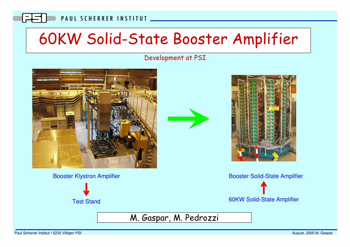
60KW Solid-State Booster Amplifier
M. Gaspar, M. Pedrozzi
Booster Klystron Amplifier
Test Stand
Booster Solid-State Amplifier
60KW Solid-State Amplifier
Development at PSI

Paul Scherrer Institut • 5232 Villigen PSI August, 2005 M. Gaspar
Target Specifications
Output Power: 60KW
Center Frequency: 499.652MHz
Efficiency: ~ 50%
Price: Cheaper than Klystron Amplifier
Lifetime: Longer than Klystron Amplifier
Maintenance: Easier, Hot Swap Possible
Construction: In Hause

Paul Scherrer Institut • 5232 Villigen PSI August, 2005 M. Gaspar
Proposed Design Configurations
2- 1 Tour = 10 Bars = 160 times 250W Modules Pout = 40KW max
Advantages: • Lower price possible (may save 20%)• Smaller size
Drawbacks • Requires Higher Gain Amplifier (not yet available)• No extra Power to Compensate Losses• Too Compact, Worse Maintenance
1- 2 Tours = 16 Bars = 256 times 250W Modules Pout = 64KW max
Advantages: • Extra Power to Compensate Losses• Uses Developped 250W Amplifier• Easier Maintenance• Only Half of the Amplifier may beused if needed
Drawbacks • Slightly Bigger Size
1.8
m

Paul Scherrer Institut • 5232 Villigen PSI August, 2005 M. Gaspar
60KW Amplifier Schematics
2KW
250W
30W
2KW
250W
250W
32KW
125W

Paul Scherrer Institut • 5232 Villigen PSI August, 2005 M. Gaspar
Components AvailablePower Supply: 3 Different Models Commercially Available (Industry)
Power Splitter: 2 8-Way and 1 4-Way Prototypes working (PSI Design)
250W Amplifier Module: 2nd Prototype working (PSI Design)
Cooling Bar: Use Soleil Design (Should Keep Compatibility) (Industry)
Circulator + Load: Commercially Available (Industry) (Already Tested)
Components Under Development @ PSI
Control System: Local (Amplifier Module) and Main Controllers
Power Splitter: 1 2-Way, 1 4-Way and 1 8-Way Low Loss High Isolation
250W Amplifier Module: Closed Case and Test-bench Cooling Plate
Power Combiner: 8-Way and 2-Way Coax
Power Coupler: 2KW and 32 KW Types

Paul Scherrer Institut • 5232 Villigen PSI August, 2005 M. Gaspar
250W Amplifier – The Key Component
Key Performance Parameters
3D-View of the 2nd Prototype
~ 50%~ 50%Efficiency
11dB12dBGain
290W250WOutput Power(with Circulator)
MaxOperation

Paul Scherrer Institut • 5232 Villigen PSI August, 2005 M. Gaspar
250W Amplifier – Measurement Results
1K 2
1K
2112
22
22
2
11 >∆+−
=−
SS
SS
1 21122211
<∆−=∆ SSSS
Stability Factor K
Pulsed Mode – Gate-width=400µµµµs f=2Hz Rise-time>10µµµµs

Paul Scherrer Institut • 5232 Villigen PSI August, 2005 M. Gaspar
250W Amplifier – Working Prototype
Radiator
Circulator
Load
300W Push-Pull
Transistor
Paul Scherrer Institut • 5232 Villigen PSI August, 2005 M. Gaspar
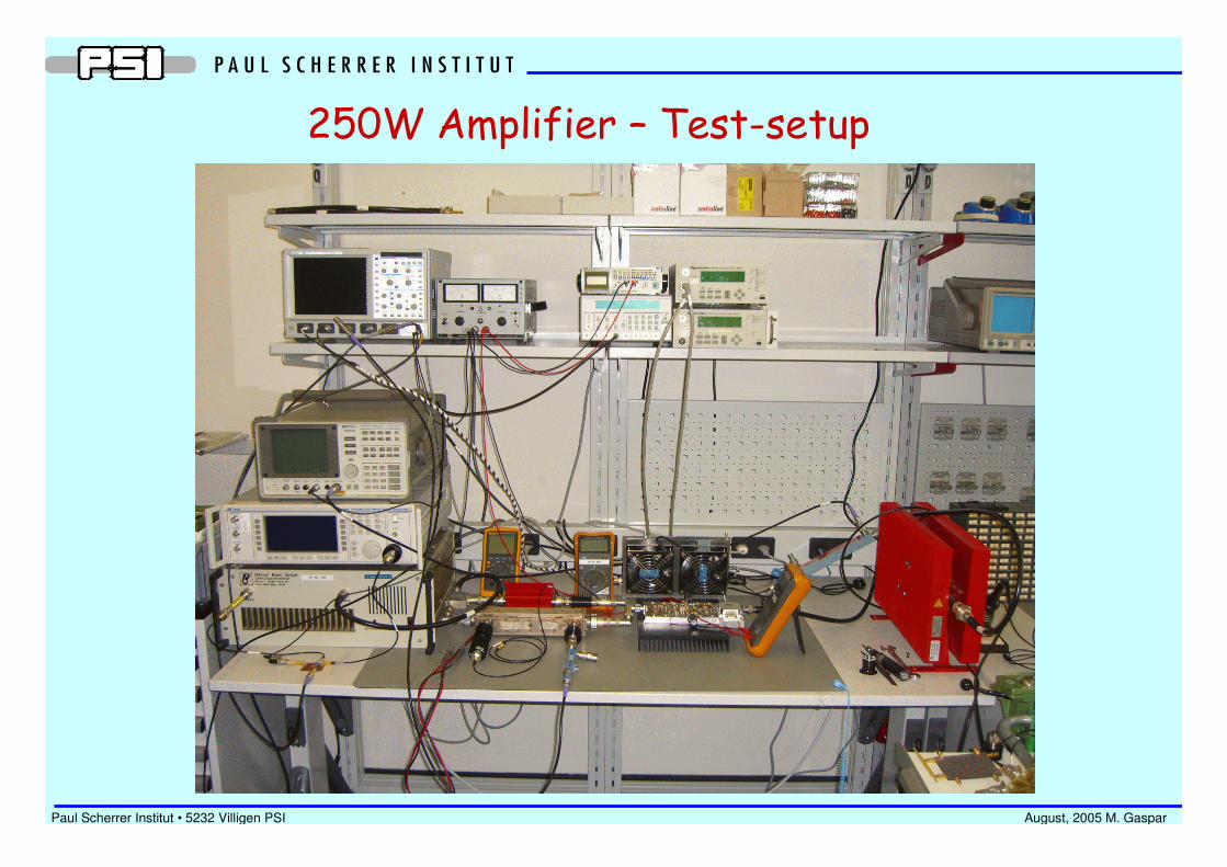
250W Amplifier – Test-setup
Paul Scherrer Institut • 5232 Villigen PSI August, 2005 M. Gaspar
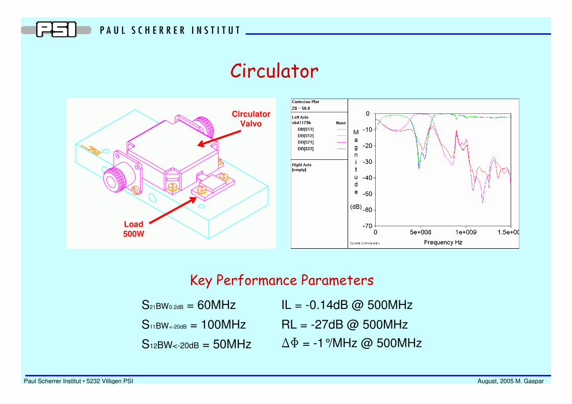
Circulator
S21BW0.2dB = 60MHz
S11BW<-20dB = 100MHz
S12BW<-20dB = 50MHz
Key Performance Parameters
IL = -0.14dB @ 500MHz
RL = -27dB @ 500MHz
DFDFDFDF = -1°/MHz @ 500MHz
Load500W
CirculatorValvo

Paul Scherrer Institut • 5232 Villigen PSI August, 2005 M. Gaspar
Power Splitter
3 Configurations Available
• 4 Channels – FR4• 8 Channels – Teflon
• 8 Channels – Suspended Substrate
Designs in Progress
• 2 Channels – Teflon 3mm• 8 Channels – Teflon 3mm improved isolation• 4 Channels – Teflon 1.6mm
S21BW-0.1dB = 80MHz
S11BW<-20dB = 100MHz
IL = -0.02dB @ 500MHz
RL = -29dB @ 500MHz
DFDFDFDF = -0.3°/MHz @ 500MHz
Measurement Results – 8-Channels TeflonPrototypes

Paul Scherrer Institut • 5232 Villigen PSI August, 2005 M. Gaspar
Supervision and Control
• Voltages
• Currents
• Temperatures
• Water Flow
• Water Temperature
• Interlocks
• RF Power/Phase
• RF Switch/Modulator

Paul Scherrer Institut • 5232 Villigen PSI August, 2005 M. Gaspar
RF Amplifier
Power Supply
Temperature Sensors
Flow Meter
Colling Bar
Water Inlet
Water Outlet
Power Distribution Cooling Bar – Fundamental Component
All Basic Requirements in One Component
• Mechanical Support
• Power Distribution
• Water Cooling• Easy Maintenance and Accessibility
Cooling Requirements
Ptotal = 5800W
Flux = 10 l/min
∆Θ = 8.3°C
High RF Power Density
~ 0.2 W/cm3

Paul Scherrer Institut • 5232 Villigen PSI August, 2005 M. Gaspar
Estimated Project Budget in CHF
Power Amplifier Modules:
Power Supply:
RF Cabling:
General Assembly:
Cooling System:
Supervision and Control:
200000
70000
10000
30000
30000
10000
Estimated Total: 350000