614.00036. · pdf fileac breaker dc distribution box surge arrestor fuse dc breaker electric...
TRANSCRIPT


52
5256
57
57575757
37
373839
3536
1.1 Scope of Validity
This manual is an integral part of inverter, and it describes the assembly, installation, commissioning, maintenance and failure search of the below inverters. Please read it carefully before operating.
1 Notes on This Manual
1.2 Target GroupThis manual is for qualified electricians. The tasks described in this manual onlycan be performed by qualified electricians.
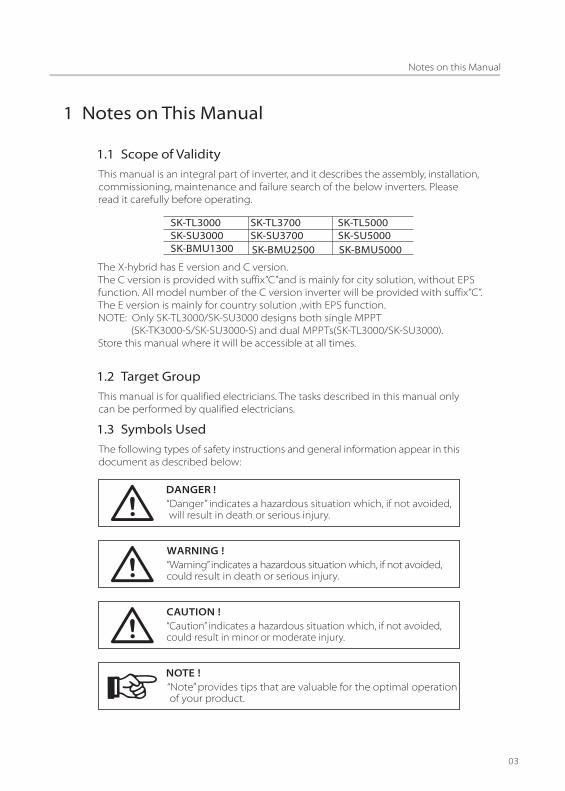
1.3 Symbols Used
The following types of safety instructions and general information appear in thisdocument as described below:
“Danger” indicates a hazardous situation which, if not avoided, will result in death or serious injury.
DANGER !
“Warning” indicates a hazardous situation which, if not avoided, could result in death or serious injury.
WARNING�!
“Caution” indicates a hazardous situation which, if not avoided, could result in minor or moderate injury.
CAUTION�!
“Note” provides tips that are valuable for the optimal operation of your product.
NOTE�!
SK-TL3000 SK-TL3700 SK-TL5000 SK-SU3000 SK-SU3700 SK-SU5000 SK-BMU1300 SK-BMU2500 SK-BMU5000
The X-hybrid has E version and C version. The C version is provided with suffix”C”and is mainly for city solution, without EPSfunction. All model number of the C version inverter will be provided with suffix”C”.The E version is mainly for country solution ,with EPS function.NOTE: Only SK-TL3000/SK-SU3000 designs both single MPPT (SK-TK3000-S/SK-SU3000-S) and dual MPPTs(SK-TL3000/SK-SU3000).Store this manual where it will be accessible at all times.

2 Safety2.1 Appropriate Usage
X-hybrid inverter(E version)
Load
Current sensor﹡
Electricalgrid
PV array
AC distribution box
*Fuse
*Battery
Surge arrestorFuse
AC Breaker
DC distribution box
Surge arrestorFuse
DC Breaker
Electric meter,bidirectional
Grid EPS
EPS contactor
EPSLoad
L line
CT
Public Grid
Breaker
The X-hybrid includes :- Hybrid ready inverter SK-TL which can convert the DC current of the PV generator into AC current for on grid or off grid usage. - Hybrid inverter SK-SU, which can store the energy in the battery for self-use and also can convert the DC current of the PV generator into AC current for on grid or off grid usage.- Hybrid battery management unit (BMU), which can work together with the SK-TL to implement a battery storage system.- X-hybrid E version with EPS can supply the energy from battery and PV generator when the grid is lost.
Note: ﹡For SK-TL series , the fuse and battery are not used �﹡The CT can be replaced with meter if necessary. ﹡The EPS function is only for E version

Induced surges are the more likely cause of lighting damage in majority or installations,especially in rural areas where electricity is usually by long overhead lines. Surgemay be included on both the PV array conduction and the a.c. cables leading tothe building.
Specialists in lighting protection should be consulted during the end use application.Using appropriate external lighting protection, the effect of a direct lightningstrike into a building can be mitigated in a controlled way, and the lightningcurrent can be discharged into the ground.
Installation of SPDs to protect the inverter against mechanical damage andexcessive stress include a surge arrester in case of a building with externallightning protection system (LPS) when separation distance is kept.
To protect the d.c. system, surge suppression device (SPD type2) should be fittedat the inverter end of the d.c cabling and at the array, located between theinverter and the PV generator, if the voltage protection level (VP) of the surgearresters is greater than 1100V, a additional SPD type 3 required for surge protectionfor electrical devices.
To protect the a.c system, surge suppression devices (SPD type2) should befitted at the main incoming point of a.c supply (at the consumer’s cutout), located between the inverter and the meter/distribution system; SPD (testimpulse D1) for signal line according to EN 61632-1.
All d.c cables should be installed to provide as short runs as possible, and positiveand negative cables of the same string or main d.c supply should be bundledtogether. Avoiding the creation of loops in the system. This requirement forshort runs and bundling includes any associated earth/bundling conductors.
Spark gap devices are not suitable to be used in d.c circuits as once conducting,they won’t stop conducting until the voltage across their terminals is typicallymore than 30 volts.
2.2 Important Safety Instructions
• All work on the inverter must be carried out by qualified electrician.• The appliance is not to be used by children or persons with reduced physical sensory or mental capabilities, or lack of experience and knowledge, unless they have been given supervision or instruction.• Children should be supervised to ensure that they do not play with the appliance.
DANGER�!DANGER TO LIFE DUE TO HIGH VOLTAGES IN THE INVERTER�!
Surge protection devices (SPDs) for PV installation
Over-voltage protection with surge arresters should be providedwhen the PV power system installed.The grid connected inverter is not fitted with SPDs in both PVinput side and MAINS side.
WARNING�!
Lighting can cause damage either from direct strike or from surges due to a nearbystrike.
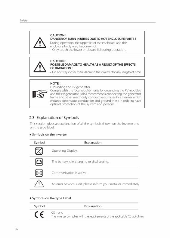
2.3 Explanation of Symbols
This section gives an explanation of all the symbols shown on the inverter andon the type label.
During operation, the upper lid of the enclosure and the enclosure body may become hot.• Only touch the lower enclosure lid during operation.
CAUTION�!DANGER OF BURN INJURIES DUE TO HOT ENCLOSURE PARTS�!
• Do not stay closer than 20 cm to the inverter for any length of time.
CAUTION�!POSSIBLE DAMAGE TO HEALTH AS A RESULT OF THE EFFECTSOF RADIATION�!
NOTE�!
Symbols on the Inverter
Symbol Explanation
Operating Display.
The battery is in charging or discharging.
Communication is active.
An error has occurred, please inform your installer immediately.
Symbols on the Type Label
Symbol Explanation
CE mark.The inverter complies with the requirements of the applicable CE guildlines.
Grounding the PV generator. Comply with the local requirements for grounding the PV modulesand the PV generator. SolaX recommends connecting the generatorframe and other electrically conductive surfaces in a manner whichensures continuous conduction and ground these in order to haveoptimal protection of the system and persons.

TUV certified.
RCM remark.
SAA certification.
Beware of hot surface.The inverter can become hot during operation. Avoid contact during operation.
Danger of high voltages.Danger to life due to high voltages in the inverter!
Danger.Risk of electric shock!
Observe enclosed documentation.
The inverter can not be disposed of together with the household waste. Disposal information can be found in the enclosed documentation.
Don’t work on this inverter until it is isolated from battery,mains and on-site PV generation suppliers.
Danger to life due to high voltage.There is residual voltage in the inverter which needs 5 min to discharge.• Wait 5 min before you open the upper lid or the DC lid.
Important Safety Instructions
When using the product, please do remember the below information to avoidthe fire, lightning or other personal injury:
Ensure input DC voltage ≤Max. DC voltage . Over voltage may causepermanent damage to inverter or other losses, which will not beincluded in warranty! This chapter contains important safety andoperating instructions. Read and keep this Operation Guide forfuture reference.
WARNING�!
WARNING�!
• Read all instructions, cautionary markings on the inverter, and all appropriate sections of this manual before using this inverter.
Authorized service personnel must disconnect both AC and DCpower from the X-hybrid inverter before attempting anymaintenance or cleaning or working on any circuits connected tothe X-hybrid inverter.

PE Connection and Leakage Current
• The end-use application shall monitoring of the protective conductor by residual current operated protective device (RCD) with rated fault current Ifn≤240mA which automatically disconnects the device in case of a fault.• DC differential currents are created (caused by insulation resistance and through capacities of the PV generator). In order to prevent unwanted triggering during operation, the rated residual current of the RCD has to be min 240mA.The device is intended to connect to a PV generator with a capacitance limit ofapprox 700nf.
High leakage current!Earth connection essential before connecting supply.
WARNING�!
• Incorrect grounding can cause physical injury, death or equipment malfunction and increase electromagnetic.• Make sure that grounding conductor is adequately sized as required by safety regulations.• Do not connect the ground terminals of the unit in series in case of a multiple installation. This product can cause current with a d.c component, Where a residual current operated protective (RCD) or monitoring (RCM) device is used for protection in case of direct or indirect contact, only an RCD or RCM of type B is allowed on the supply side of this product.• For Australia and New Zealand:The installation of inverter must fulfill Australia national Wiring rules AS/NZS3000,AS/NZS4777.1 and AS/NZS5033.
Do not work on the inverter when the device is running.WARNING�!
• Never touch either the positive or negative pole of PV or battery connecting device. And never ever touch both at the same time.
Risk of electric shock!WARNING�!
• Use only attachments recommended or sold by SolaX.• Make sure that existing wiring is in good condition and that wire is not undersized. Do not operate the X-Hybrid Series inverter with damaged or substandard wiring.• Do not disassemble the X-Hybrid Series inverter. It contains no user-serviceable parts. See Warranty for instructions on obtaining service. Attempting to service the X-Hybrid Series inverter yourself may result in a risk of electric shock or fire and will void your warranty. • Keep away from flammable, explosive materials to avoid fire disaster.• The installation place should be away from humid or corrosive substance.• Authorized service personnel must use insulated tools when installing or working with this equipment.• PV modules shall have an IEC 61730 class A rating.

• The unit contains capacitors that remain charged to a potentially lethal voltage after the MAINS , battery and PV supply has been disconnected.• Hazardous voltage will present for up to 5 minutes after disconnection from power supply.• CAUTION-RISK of electric shock from energy stored in capacitor, never work on the solar inverter couplers. The MAINS cable, Battery cable, PV cables or the PV generator when power is applied. After switching off the PV , battery and Mains, always wait for 5minutes to let the intermediate circuit capacitors discharge before you unplug DC ,battery inplug and MAINS couplers.• When access to internal circuit of solar inverter, it is very important to wait 45 minutes before working on power circuit or demounting the electrolyte capacitors inside the device. Do not open the device before hand since the capacitors require this long to discharge sufficiently!• Measure the voltage between terminals UDC+ and UDC- with a multi-meter (impedance at least 1Mohm) to ensure that the device is discharged before beginning work (35VDC) inside the device.
2.4 EC Directives
This chapter follows the requirements of the European low voltage Directives, which contains the safety instructions and conditions of acceptability for the endues system, which you must follow when installing, operating and servicing the unit. If ignored, physical injury or death may follow, or damage may occur to the unit. Read this instructions before you work on the unit. If you are unable to understand the dangers, warnings, cautions or instructions, contact the manufacturer if an authorized service dealer before installing. Operating andservicing the unit.
The X-Hybrid inverter meets the requirement stipulated in Low voltageDirective (LVD) 2006/95/EC and Electromagnetic compatibility (EMC) Directive2004/108/EC. The unit is tested based on:
EN 50178:1997EN 62109-1:2010EN 62109-2:2011VDE 0126-1-1:2006VDE 4105:2011
In case of installation in PV system, startup of the unit (i.e. start of designatedoperation) is prohibited until it is determined that the full system meets therequirements stipulated in EC Directive (2006/95/EC,2004/108/EC, etc.)
The X-Hybrid inverter leaves the factory completely connecting deviceand ready for connection to the mains , Battery and PV supply. The unit shall be installed in accordance with national wiring regulations. Compliance with safety regulations depends upon installing and configuring system correctly, including using the specified wirings. The system must be installed only by professional assemblers who are familiar with requirements for safety and EMC. The assembly is responsible for ensuring that the end system complies with all the relevant laws in the country where it is to be used.
The individual subassembly of the system shall be interconnected by means ofthe wiring methods outlined in national/international such as the national electriccod (NFPA) No.70 or VDE regulation 0107.

3 Introduction
3.1 Basic Feature and Different Working Modes
The X-Hybrid series including X-Hybrid ready inverter, X- Hybrid inverter and X-Hybrid battery management unit. With all these function modules, you candesign your own PV Hybrid storage system as you needed. The Hybrid system need to be build with either a X-Hybrid ready inverter, a battery management unit and a battery system or a X-Hybrid inverter and a battery system. We have the below working modes for your home made energy storage system. • Self Use In the “Self Use” mode the priority of the PV generated power will be : local load> battery> public grid. It means the PV generated power will be used in local load then the battery charging and the redundancy power will be delivered to the public grid.• Force Time Use In the “Force Time Use” mode, user can set the charging and discharging time according to his wishes and also can chose if charge from grid if allowed.• Export control When the user set the export control value, the inverter can limit the energy feed in to the grid.• EPS mode The X-Hybrid E version integrated with EPS function. The inverter will automatically switch to EPS output when the grid is off. User need to set the battery remaining value for the EPS. When use the EPS function, need to fit the load power rating with the EPS power rating.
3.2 Terminals of X-Hybrid Ready Inverter, X-Hybrid Inverterand BMU
X-Hybrid Inverter (SK-SU)
• Make sure the load powering rating is within the EPS’s output rating, Or the inverter will shutdown with an “over load “ warning .• When an “over load” is appeared, adjust the load power make sure it is with the rang of the EPS output, and turn the inverter on.• For the nonlinear load ,please pay attention to the inrush power make sure it is within the range of the EPS output.
WARNING�!
A B C D E F G HJ
IK L
TEMP
O
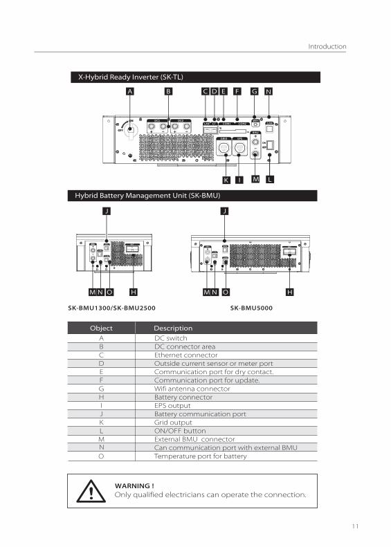
Hybrid Battery Management Unit (SK-BMU)
Object DescriptionABCDEFGHIJKLM
DC switchDC connector areaEthernet connectorOutside current sensor or meter portCommunication port for dry contact.Communication port for update.Wifi antenna connectorBattery connectorEPS outputBattery communication portGrid outputON/OFF buttonExternal BMU connectorCan communication port with external BMUTemperature port for battery
Only qualified electricians can operate the connection. WARNING�!
J
HMN
BMUBMU
M M N
J
H OO
SK-BMU5000SK-BMU1300/SK-BMU2500
NO
X-Hybrid Ready Inverter (SK-TL)
L
A B C D E F G
BMU
IK LM
N

475mm
59
1m
m
151mm
59
1m
m
294mm 151mm
59
1m
m
449mm 151mm
3.3 Dimension
700mm5
91
mm
151mm
Dimension for SK-TL Series
Dimension for SK-BMU Series
Dimension for SK-SU Series
SK-BMU1300/SK-BMU2500 SK-BMU 5000

3.4 Identification of X-Hybrid
Model Name
Manufacture Info
Parameter Series Number Labels
Model SK-TL(SU)3000 (S) SK-TL(SU)3700 SK-TL(SU)5000
Max. DC input power (W)
DC input Voltage range(V)
MPP voltage range(V)
Rated input voltage(V)
Start input voltage(V)
Max. DC input current perinput (A)
Max. short-circuit currentper input (A)
No. of MPP inputs
No. of strings per MPP input
DC Disconnection switch
3300
100-550
125-530
360
100
12/12(12)
15/15(15)
2(1)
1
Optional
4000
100-550
125-530
360
100
12/12
15/15
2
1
Optional
5000
100-550
125-530
360
100
12/12
15/15
2
1
Optional
4 .1 DC Input
4 Technical Data for X-Hybrid Inverter

4.2 AC Output
Model SK-TL(SU)3000 SK-TL(SU)3700 SK-TL(SU)5000
Rated output power@ cosφ=1(W)
Max. apparent AC power(VA)
Rated grid voltage(V)
AC voltage range(V)
AC nominal current(A)
Max. output current(A)
Max. short-circuit current(A)
The harmonic factor if outputCurrent at AC THD voltage<2%AC power>0.5 nominal AC power
Rated AC frequency(Hz)
Rated AC frequency range(Hz)
Max. inverter backfeed current tothe array(mA)
Inrush current(A)
Maximum output fault current(A)
Maximum output overcurrentprotection(A)
Displacement power factor, adjustable
Feed in phase
Over voltage category
3000
3000
230
180~270
13
14.4
40
<3%
50/60
44-55/55-65
500
60
150
25
3680
3680
230
180~270
16
16
40
<3%
50/60
44-55/55-65
500
60
150
25
4600
4600
230
180~270
20
21.7
50
<3%
50/60
44-55/55-65
500
60
150
25
0.8 leadiing...0.8 lagging
Single-phase
III (electric supply side), II (PV side)
4.3 EPS Output With Internal Charger ( E Version for SK-SU)
Model SK-SU3000 SK-SU3700 SK-SU5000
Rated voltage (V)
Rated frequency(Hz)
Rated current (A)
EPS Peak power[VA]
Swtich time(s)
230
50/60
9
1.5×Prated, 10s
<5
EPS rated power [VA] 2000
Total harmonic distortion (THD) <3%
AC input voltage(V)
AC input current(A)
AC input frequency(HZ)
230 230 230
13 13 13
50/60 50/60 50/60

4.4 Efficiency, Safety and Protection
Model SK-TL(SU)3000 SK-TL(SU)3700 SK-TL(SU)5000
Max. Efficiency
Euro Efficiency
MPPT Efficiency
Safety & Protection
Over voltage/under voltageprotection
DC isolation impedance
Monitoringground fault protection
Grid monitoring
Ground fault current monitoring
DC injection monitoring
Back feed current monitoring
Residual current detection
Anti-islanding protection
Over load protection
Over heat protection
97.6%
97.0%
99.9%
YES
YES
YES
YES
YES
YES
YES
YES
YES
YES
YES
Battery nominal voltage [V]
Battery voltage range [V]
Max. charge/discharge current [A]
Discharge depth (%)
Charging curve
Communication interfaces
48
40-60
50(adjustable)
80%(adjustable)
3-stage adaptive with maintenance
Can/RS232
97.6%
97.0%
99.9%
YES
YES
YES
YES
YES
YES
YES
YES
YES
YES
YES
97.6%
97.0%
99.9%
YES
YES
YES
YES
YES
YES
YES
YES
YES
YES
YES
4.5 Internal Charger ( for SK-SU)
Model SK-SU3000 SK-SU3700 SK-SU5000
Battery type Lead-acid battery/Lithium battery
Battery temperature sensor Yes
Winter mode Yes
5 Technical Data for X-Hybrid BMU
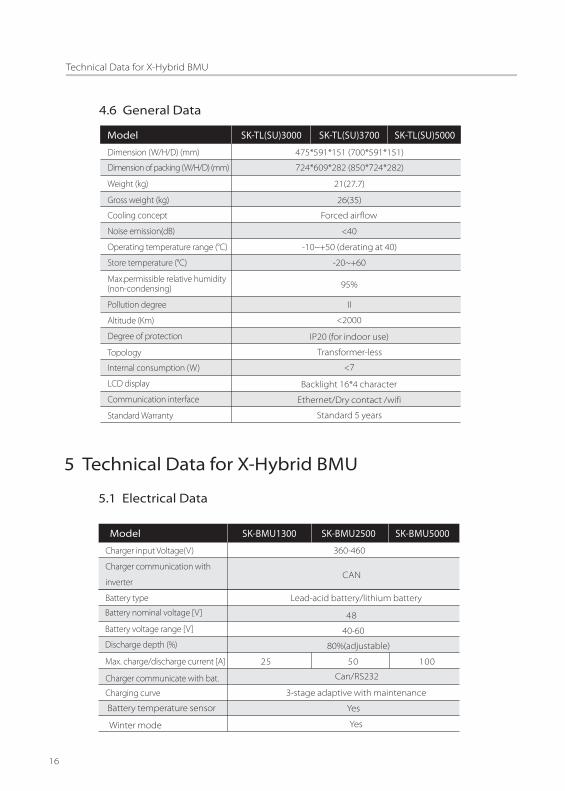
4.6 General Data
Model SK-TL(SU)3000 SK-TL(SU)3700 SK-TL(SU)5000
Dimension (W/H/D) (mm)
Dimension of packing (W/H/D) (mm)
Weight (kg)
Gross weight (kg)
Cooling concept
Noise emission(dB)
Operating temperature range (°C)
Store temperature (°C)
Max.permissible relative humidity(non-condensing)
Pollution degree
Altitude (Km)
Degree of protection
Topology
Internal consumption (W)
LCD display
Communication interface
Standard Warranty
475*591*151 (700*591*151)
724*609*282 (850*724*282)
21(27.7)
26(35)
Forced airflow
<40
-10~+50 (derating at 40)
-20~+60
95%
II
<2000
IP20 (for indoor use)
Transformer-less
<7
Backlight 16*4 character
Ethernet/Dry contact /wifi
Standard 5 years
Model SK-BMU1300
Charger input Voltage(V)
Charger communication with
inverter
Battery type
Charging curve
Lead-acid battery/lithium battery
3-stage adaptive with maintenance
5.1 Electrical Data
SK-BMU2500 SK-BMU5000
360-460
CAN
Discharge depth (%)
48
40-60Battery voltage range [V]
Battery nominal voltage [V]
80%(adjustable)
Max. charge/discharge current [A]
Charger communicate with bat. Can/RS232
25 50 100
Battery temperature sensor
Winter mode
Yes
Yes
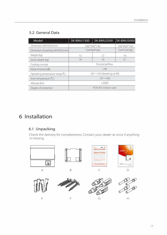
6.1 UnpackingCheck the delivery for completeness. Contact your dealer at once if anything is missing.
A B C D
E F G H
6 Installation
Dimension (W/H/D) (mm)
Dimension of packing (W/H/D) (mm)
Weight (kg)
Gross weight (kg)
Cooling concept
Noise emission(dB)
Altitude (Km)
Degree of protection
Forced airflow
<40
-20∼+50 (derating at 40)
-20∼+60
<2000
IP20 (for indoor use)
5.2 General Data
Model SK-BMU1300 SK-BMU2500 SK-BMU5000
592*290*140 592*450*140
12 12 1616 16 21
724*409*282 724*579*282

Object Quantity Description
A
B
C
D
EF
G
H
J
K
L
M
X-hybrid Series inverter
Bracket
Warranty card
User manual
DC connectors2 units (1* positive ,1* negative) for SK-TL3000/SK-SU3000
Expansion tubes
10 pin terminal block male connector for dry connector.
Wrench tool for separate DC connector
Battery connecter (for SK-SU only)
Current sensor
RJ 45 extend port for current sensor
WIFI antenna
1
1
1
1
44
2/4
2/4
1
1
1
1
4 units (2* positive ,2* negative)
O
P
1
1
Expansion screws
2 units (1* positive ,1* negative) for SK-TL3000/SK-SU30004 units (2* positive ,2* negative)
DC Pin contact
I 1 AC connector
Q
R
1 Battery thermal sensor (for SK-SU only)
N
EPS connector(only for E-version)
1
WIFI setting guide1S
1 Quick installation guide

Open the package and pick the product, check that if there is any distortion or impaired during the transportation. Meanwhile, check that if the relating accessories and the materials are here, you can see the accessories list in the table.The instruction manual is an integral part of the unit and should therefore be read and kept carefully.It is recommended that the packaging should not be removed until the unitis located in the installation site.
6.2 Check for Transport DamageCheck if the X-hybrid series inverter has some visible external damage , suchas cracks in the housing or display please contact with your dealer if you findany damage.
6.3 Installation PrecautionThe X-hybrid series inverter is designed for indoor installation (IP20)Make sure the installation site does not fall into one of the following conditions:
• Do not install the inverter in direct sunlight.• Do not install the inverter on flammable construction material.• Do not install the inverter in areas where highly flammable materials are stored.• Do not install the inverter in potentially explosive areas.• Do not install the inverter during periods of precipitation or high humidity (>95%); Moisture trapped within the location may cause corrosion and damage to the electric components.• Provide adequate ventilation when using batteries, and also read the warning label on the bottom of the inverter.• Install the inverter in a location that maintains an ambient air temperature that is less than 40°C;That is to maintain a safe internal component temperature, the inverter would reduce power if the ambient air temperature exceeds 40°C.• The inverter should be installed in a location that is not accessible for children.• The inverter emits a slight vibrating noise when operating, which is normal and no effect on performance.• The slope of the wall should be within ±5°.• The inverter is heavy, ensure the mounting place is strong enough to hold the weight of the inverter.• If you install the inverter in a cabinet, closet or other small enclosed area, sufficient air circulation must be provided in order to dissipate the heat generated by the unit.

Before installation and maintenance, AC and DC side doesn’t carryelectricity, but if DC side is just disconnected, capacitance still containselectricity, so please wait for at least 5 minutes to ensure the capacitorscompletely release the energy and inverter is not electrified.
WARNING !
Inverters should be installed by technicians.NOTE!

6.4 Preparation Below tools are needed before installation.
Installation Tools
Installation Tools: crimping pliers for binding post and RJ45, screwdriver, manualwrench, ф 6 driller and rubber hammer.
The unit is heavy. Do not lift it alone.
Lifting and Handling
• During lifting procedures ensure that the unit is firmly secured to avoid the risk of accidental tipping or dropping.• Parts serving for support or immobilization of unit shall be designed and manufactured so as to minimize the risk of physical injuries and of accidental loosening of fixing.• Ensure that the method of lifting will not allow the unit to slip from chains and slings or turn-over or slide from lifting devices.• Transportation must be carried by specialized person (truck operators. Hook-up personal), equipped with the necessary protection equipments (overalls, safety shoes, protective gloves, helmets, goggles)• Do not walk or stand beneath or in the proximity of the load.• Avoid sudden movements and jolts when unloading and positioning the unit. Internal handling procedures must be conducted with care. Do not exert leverage on the components of the machine.• If the unit is not balanced apply ballast. Any protruding parts should not be supported by hand.• The inverter should be installed so that the operating panel shall be easily accessible- easy access to the electrical power connection point.• Accessible for maintenance and repair work.• Parts serving for support or immobilization of unit shall be designed and manufactured so as to minimize the risk of physical injuries and accidental loosening of fixings.
• Loading capacity and hardness of the supporting surface, load rating of mounting bracket should be at least four times the weight of the devices according to IEC62109-1. and supporting characteristics will be impaired by wear, corrosion, material fatigue or ageing, This should be calculated by inspection of the design data of supporting material and consulting construction engineer.

6.5 Installation Steps
Step1: Screw The Wall Bracket on The Wall• Use the wall bracket as a template to mark the position of the 4 holes.• Drill holes with ф6 driller carefully, make sure the holes are deep enough (at least 50mm) for install and tight the expansion tubes.• Install the expansion tubes in the holes, and tight them . Install the wall bracket using the expansion screws in the screw package.
Step2: Hang the X-hybrid Inverter On the Wall Bracket.• Transportion of the inverter needs at least 2 people, each one needs to use the handles at the sides of the inverter.• Hang the inverter over the bracket, move the inverter close to it, slightly laydown the inverter make sure the 4 mounting bars on the back of the inverter is fixed well with the 4 grooves on the bracket.
Note:The installation of SK-BMU is the same as above.
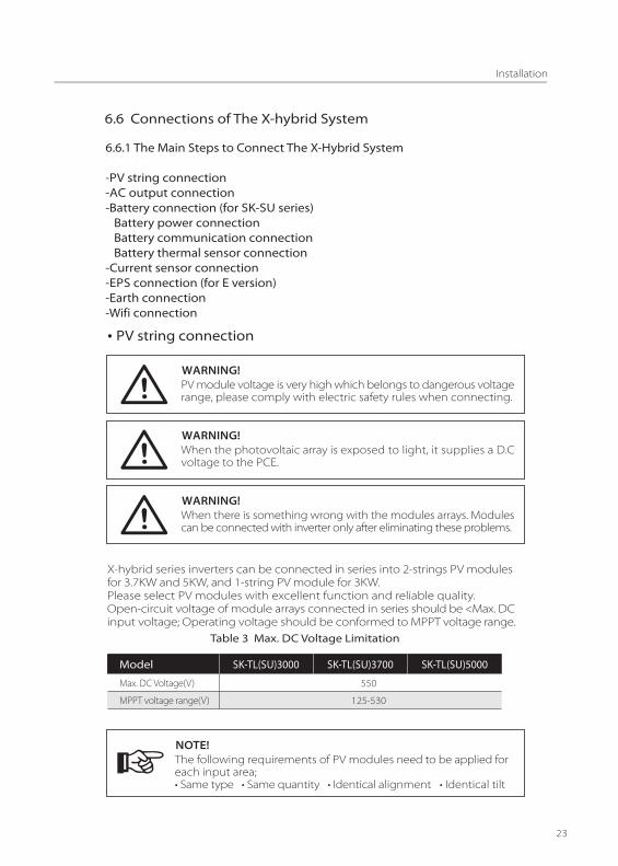
PV module voltage is very high which belongs to dangerous voltagerange, please comply with electric safety rules when connecting.
WARNING!
When the photovoltaic array is exposed to light, it supplies a D.Cvoltage to the PCE.
WARNING!
When there is something wrong with the modules arrays. Modulescan be connected with inverter only after eliminating these problems.
WARNING!
Ÿ PV string connection
The following requirements of PV modules need to be applied foreach input area;• Same type • Same quantity • Identical alignment • Identical tilt
NOTE!
6.6 Connections of The X-hybrid System
6.6.1 The Main Steps to Connect The X-Hybrid System
-PV string connection-AC output connection-Battery connection (for SK-SU series) Battery power connection Battery communication connection Battery thermal sensor connection-Current sensor connection-EPS connection (for E version)-Earth connection-Wifi connection
X-hybrid series inverters can be connected in series into 2-strings PV modulesfor 3.7KW and 5KW, and 1-string PV module for 3KW. Please select PV modules with excellent function and reliable quality. Open-circuit voltage of module arrays connected in series should be <Max. DC input voltage; Operating voltage should be conformed to MPPT voltage range.
Table 3 Max. DC Voltage Limitation
Model SK-TL(SU)3000 SK-TL(SU)5000
Max. DC Voltage(V)
MPPT voltage range(V)
550
125-530
SK-TL(SU)3700

Please use PV cable to connect modules to inverter. From junction box to inverter,voltage drop is about 1-2%. So we suggest the inverter install near PV module,in order to save cable and reduce DC loss. (No longer than 30m)
Please do not make PV positive or negative ground!NOTE!
• Use multimeter to measure module array voltage• Check the PV+ and PV- from the PV string combiner box correctly.Make sure the PV+ and PV- connected correctly.
Ÿ Connection Step:1. Disconnect the DC switch.2. Choose 12 AWG wire to connect the PV module.3. Trip 6mm of insulation from the Wire end.
4. Separate the DC connector as below.
5. Insert striped cable into pin contact and ensure all conductor strands are captured in the pin contact.6. Crimp pin contact by using a crimping pliers. Put the pin contact with striped cable into the corresponding crimping pliers and crimp the contact.
7 Insert pin contact through the cable nut to assemble into back of the . male or female plug. When you feel or heard a “click” the pin contact assembly is seated correctly.
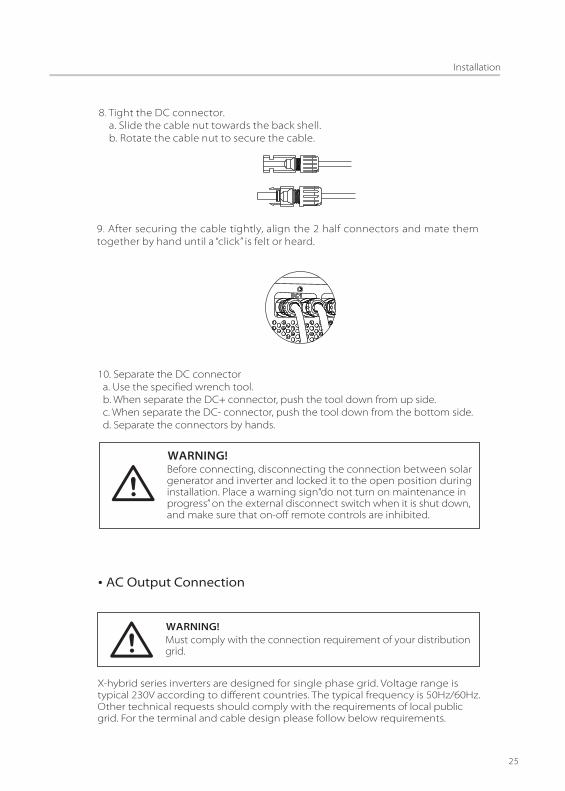
8 Tight the DC connector.. a. Slide the cable nut towards the back shell. b. Rotate the cable nut to secure the cable.
9 After securing the cable tightly, align the 2 half connectors and mate them . together by hand until a “click” is felt or heard.
10. Separate the DC connector a. Use the specified wrench tool. b. When separate the DC+ connector, push the tool down from up side. c. When separate the DC- connector, push the tool down from the bottom side. d. Separate the connectors by hands.
Before connecting, disconnecting the connection between solargenerator and inverter and locked it to the open position duringinstallation. Place a warning sign“do not turn on maintenance inprogress” on the external disconnect switch when it is shut down,and make sure that on-off remote controls are inhibited.
WARNING!
Must comply with the connection requirement of your distributiongrid.
WARNING!
Ÿ AC Output Connection
X-hybrid series inverters are designed for single phase grid. Voltage range is typical 230V according to different countries. The typical frequency is 50Hz/60Hz. Other technical requests should comply with the requirements of local publicgrid. For the terminal and cable design please follow below requirements.
26
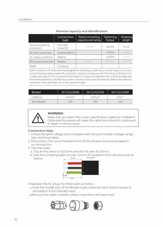
Terminal capacity and Identification.
Connectiontype
Rated connectingcapacity and rating
Strippinglength
Tighteningtorque
Torx-headScrew(m5)
Amphenol(MC4)
Wieland
Wieland
Connector
1.8-2Nm
1.8-2Nm
1.8-2Nm
-----------
11mm
-----------
-----------
-----------
Protective earthingconnection
DC input connection
AC output connection
EPS output connection
RS485
-----------
-----------
Earth conductor: PE screw terminal designed for clamping a cable lug or bar by means of a screw, nut and locking washer, before PE connection, strip the conductor end 12mm long to fit them intoa cable lug or bar. For PE connection, the length of conductors between the cord anchorage andthe terminal,shall be such that the current-carrying conductors became taut before the earthingconductor if the cable slips out of the cord anchorage.
Make sure you select the correct specification cables for installation.Otherwise the power will make the cable hot or burnt, it could resultin death or serious injury
WARNING!
Connection Step:1. Check the grid voltage and compare with the permissible voltage range. (see technical data).2. Disconnect the circuit-breaker from all the phases and secure against re-connection.3. Trip the wires: a. Trip all the wires to 52.5mm and the PE wire to 55mm. b. Use the crimping pliers to trip 12mm of insulation from all wire ends as below. 52.5mm
12mm
55mm
Outer jacket
L
N
PE
4.Separate the AC plug into three parts as below. a: Hold the middle part of the female insert,rotate the back shell to loosen it, and datach it from female insert. b:Remove the cable nut(with rubber insert) from the back shell.
Model SK-TL(SU)3000 SK-TL(SU)5000
Cable(Cu)
Micro-Breaker
4-5mm�
20A
SK-TL(SU)3700
4-5mm�
20A
5mm�
25A
27
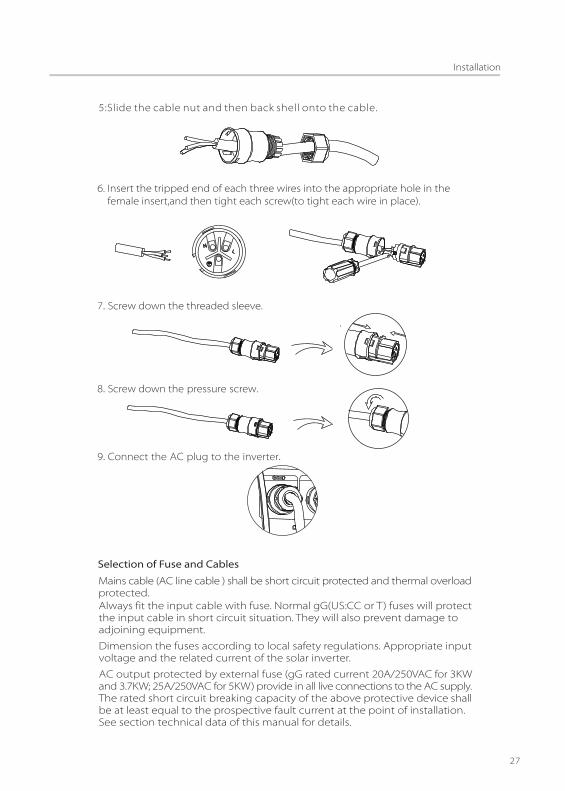
5:Slide the cable nut and then back shell onto the cable.
6. Insert the tripped end of each three wires into the appropriate hole in the female insert,and then tight each screw(to tight each wire in place).
7. Screw down the threaded sleeve.
8. Screw down the�pressure�screw.
9. Connect�the�AC�plug�to�the�inverter.
Mains cable (AC line cable ) shall be short circuit protected and thermal overloadprotected.
Selection of Fuse and Cables
Always fit the input cable with fuse. Normal gG(US:CC or T) fuses will protect the input cable in short circuit situation. They will also prevent damage to adjoining equipment.
Dimension the fuses according to local safety regulations. Appropriate input voltage and the related current of the solar inverter.
AC output protected by external fuse (gG rated current 20A/250VAC for 3KW and 3.7KW; 25A/250VAC for 5KW) provide in all live connections to the AC supply.The rated short circuit breaking capacity of the above protective device shall be at least equal to the prospective fault current at the point of installation. See section technical data of this manual for details.

Ac output cable: Cu, L, N+PE,2*5 .0+5.0mm� @40°C ambient with a max length of 5m with operating time of the fuse is less than 5seconds, installation method B2 according to EN60204-1:2006, annex D: cable in conduit cable trunking system,number of loaded circuit only one . Use H07RNF (cord designation 60245 IEC66) for an ambient temperature between 40°C and 60°C.
Note1: For conditions differing form those mentioned above ,dimension the cables according to local safety regulations, appropriate input voltage and the load and the load current of the unit.( You can choose a thicker cable but the fuses must rated according to the cable.)
Note2: Fuses must be approved by Notified Body.
Inverter is not provided galvanic isolation from the mains to the PV array, backfeed current to the array is 20A/250VAC for 3KW and 3.7KW; 25A/250VAC for 5KW,based on the fuse provided in the mains. Also in the worst case .the reversecurrent comprises the sum of the short-circuit currents of all intact lines.
There for the current-carrying capacity of the components and sub-assembliesprovided in the end-use system(connectors ,cables, junction box, switch ger,etc.).and the reverse current PV module shall be considered based on the backfeedcurrent and reverse current. The direct current (DC) circuit breaker or fusebetween each solar generator and inverter shall be provided based on solarinverter input ratings.
Select DC cables based on the above inverter back-feed current and Isc PVrating and Vmax ratings.
28
When you want to build a self-use storage system , the battery is a necessarypart. The SK-SU E version series inverter provide the necessary part of the interfacesto connect the battery to the inverter.
Make sure you select the correct specification cables for installation. Otherwise the Power will make the cable hot or burnt, it could resultin death or serious injury.
WARNING!
Battery power connection .
1. Connect one side of the battery connect wire to the inverter.2. Fit a fuse (63A slow blow) in the both positive and negative battery cable as close as possible to the battery.
Battery communication connection .
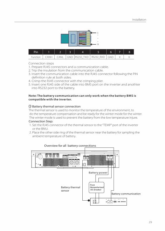
CommunicationThe communication interface between battery and inverter is RS232 or CANwith a RJ45 connector. The Pin definition is as below.
3. Connect the positive side of the battery connect wire to the positive side of the battery , the negative side of the battery connect wire to the negative side of the battery.4. Make sure the positive and negative of the battery are correct.
Ÿ Battery Connection (for SK-SU Series)
29
Connection steps1. Prepare RJ45 connectors and a communication cable.2. Trip the insulation from the communication cable.3. Insert the communication cable into the RJ45 connector following the PIN definition rule at both sides.4. Crimp the RJ45 connector with the crimping plier.5. Insert one RJ45 side of the cable into BMS port on the inverter and anothter into RS232 port to the battery.
Pin 1
Function CANH
2
CANL
3
GND
4
RS232_TXD
5
X
76
X
8
RS232_RXDGND
Note: The battery communication can only work when the battery BMS is compatible with the inverter.
RS 232RS 485
-Fuse -Nonpolarized DC breaker
Battery power
Battery communication
Battery thermal sensor
TEMP
Battery thermal sensor connectionThe thermal sensor is used to monitor the temperature of the environment, to do the temperature compensation and be ready for the winter mode for the winter. The winter mode is used to prevent the battery from the low temperature injure.Connection Step: 1. Set the RJ45 connector of the thermal sensor to the “TEMP” port of the inverter or the BMU. 2. Place the other side ring of the thermal sensor near the battery for sampling the ambient temperature of battery.
Overview for all battery connections

30
The current sensor measures the current on the phase wire that runs betweenthe inverter and the grid. This enables the inverter to determine the Powerrequirements of the connected consumer. The current sensor is connectedto the CT port on the inverter.
Connection Step:1. Insert the RJ45 terminal on the current sensor into the CT port on the inverter.2. Place the current sensor around the phase wire L which the inverter is connected.3. Place the current sensor around the phase wire L to measure the current going to or coming from the grid.4. Make sure the current sensor is installed in the right direction: The arrow on the current sensor must point to the public grid.
Ÿ Current sensor connection
X-hybrid inverter(E version)
Load
Current sensor﹡
Electricalgrid
PV array
AC distribution box
*Fuse
*Battery
Surge arrestorFuse
AC Breaker
DC distribution box
Surge arrestorFuse
DC Breaker
Electric meter,bidirectional
Grid EPS
EPS contactor
EPSLoad
L line
CT
Public Grid
Breaker

This funciton can be achieved manually or automatically according to user’s wishes.If user wants to use the off grid function manually, it need to be installed an external switch. Please refer to speci�c wiring diagram below or as described in quick installation guide.And for automatical solution, please contact SolaX.
31
When connectingthe RJ45 connector with the wire of the CT or Meter , please follow the below sequence :
Pin 1
CT Red wire
2 3 4 5
X
76
X
8
X X X X Green wire
Meter Blue wire White wireX X X X XX
• Do not place the sensor on the N Wire or the earth wire.• Do not place the sensor on the N and L wire simultaneously.• Do not place the sensor on the L wire going to the consumer.• Do not place the sensor with the arrow pointing to the generation meter.• Do not place the sensor on the non-insulated wires.• Do not use the wire over 25m.
NOTE!
● EPS connectionThe X-hybrid E version inverter has on and off grid function, the inverter will have output through the grid output when the grid is on, and will have output through the EPS output when the grid is off.
• The sensor can be upgraded to meter.• With a one phase meter provided by SolaX can monitoring the 24hr usage of electric.• With a three phase meter provided by SolaX can implement three phase compensation.
NOTE!
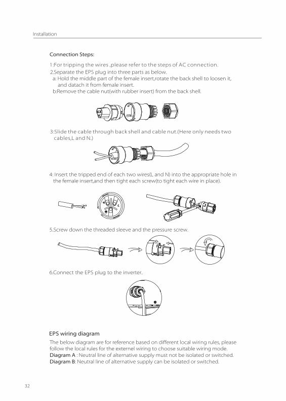
2.Separate the EPS plug into three parts as below. a: Hold the middle part of the female insert,rotate the back shell to loosen it, and datach it from female insert. b:Remove the cable nut(with rubber insert) from the back shell.
3:Slide the cable through back shell and cable nut.(Here only needs two cables,L and N.)
4: Insert the tripped end of each two wires(L and N) into the appropriate hole in the female insert,and then tight each screw(to tight each wire in place).
1:For tripping the wires ,please refer to the steps of AC connection.
5.Screw down the threaded sleeve and the�pressure�screw.
6.Connect�the�EPS�plug�to�the�inverter.
EPS wiring diagram
32
The below diagram are for reference based on different local wiring rules, please follow the local rules for the externel wiring to choose suitable wiring mode.Diagram A : Neutral line of alternative supply must not be isolated or switched. Diagram B: Neutral line of alternative supply can be isolated or switched.

SolaX meter+ -
Battery
SPDTN-BAR
E-BAR
this cable is not required
Main switch
RCD RCD
EPSLoad
PV1+
PV1 -
PV2+
PV2 -
SolaX meter+ -
Battery
DPDT
E-BAR
this cable is not required
Main switch
RCD
EPSLoad
PV1+
PV1 -
PV2+
PV2 -
RCD
PE
E
In case of discrepancies between wiring mode of local policy and the opration guide above, especially for the wiring of neutral line, grounding and RCD, please contact SolaX before any operation!
33
Diagram A
Diagram B
SolaX X-hybrid inverter
SolaX X-hybrid inverter
Type A
Type A

34
Below table shows some conventional and reasonable loads for you reference.
TypePower
Start Rated
Commonequipment
Example
Resistive load
Inductive load
Capacitive load
X 1
X 2
X 1
X 1.5
X 3~5 X 2
Start Rated
100VA (W)
100VA (W)
80VA (W)
60VA (W)
450-750VA (W)
300VA (W)
Equipment
Fluorescent lamp Fluorescent lamp
40W
Fan Fridge Fridge
150W
Incandescent lamp
TV Incandescent lamp
100W
You can additionally earth the inverter enclosure of a second earthing or equipotential bonding is required locally. This prevents touch current if the original protective conductor fails.
Cable size: 12AWG.
Connection step:1. Strip the earthing cable insulation. 2. Insert the stripped cable into the ring terminal.3. Clamp the end of the ring terminal.4. Unscrew the screw of the earthing connector.5. Suit the ring terminal on the earthing connector .Suit the gasket on the earthing connector.6. Screw the screw of the earthing connector.
Earth connection.●

35
Wifi communication interface is a standard interface, your can read the real time data in the local network by your smartphone or check the details fromthe internet either from PC or smartphone with the wifi monitoring.
Connection steps :1. Install the antenna on the inverter.2. Connect the wifi with the router. (as described in the wifi setting guide) 3. Set the station account on the SolaX web.(as described in the wifi setting guide)
● Wi� connection
6.6.2 Communication InterfaceThis product has a series communication interfaces besides WIFI , LAN, Dry contact and extend port and for human and machine communication. Operating information like output voltage, current, frequency, fault information, etc., can be delivered to PC or other monitoring equipments via these interfaces.
LAN ● CommunicationLAN communication is one standard communication interface. It transmits thedata between the router and X-hybrid series inverters in the local area network. User can set the parameters with specialized software provided by SolaX.The pin definition of the connector is as below.
● Connection steps1. Prepare two RJ45 connectors and a communication cable.2. Trip the insulation from the communication cable.3. Insert the communication cable into the RJ45 connector following the PIN definition rule.4. Crimp the RJ45 connector with the crimping plier.5. Repeat the above steps to fix the other head of the communication cable.6. Insert one side of the cable into the LAN port on the inverter, and the other side of the cable into the router or into the PC if you want to set the parameters or upgeade the software with SolaX APP.
Dry contact
● CommunicationDry contact is provided to give a remote monitor and remote control with theoptional accessory. The remote monitor function provides an indication onthe inverter's working status. The dry contact communication uses terminalblocks. The PIN definitions and the circuit connection are as below.
PinFunction
1TX+
2TX-
3RX+
4n/c
5n/c
6RX-
7n/c
8n/c

6.7 Inverter ManipulationStart inverter after checking all below steps:• Check that the device is fixed well on the wall.• Make sure all the DC wirings and the AC wirings are completed. • Make sure the CT is connected well.• Make sure the battery is connected correctly. Make sure the external EPS contactor is connected. (if needed) • Turn on the external AC ,DC switch.• Turn on the DC switch to the “ON” position.• Turn on the on/off Button on the inverter.
Start inverter• Inverter will start automatically when the PV panel generate enough energy or the battery is charged.• Check the status of LED and LCD screen, first LED should be green and the LCD screen should display the main interface.• If first LED is not green, please check the below: - All the connections are right. - All the external disconnect switches are closed. - The DC switch of the inverter is in the “ON” position.• Enter the setting interface.• Set the safety standard as page 42; Set the system time as page 42; PV connection mode as page 43; Set the work mode as page 46; Set charger as page 47; Set the EPS as page 49; Set WIFI according to the wifi manual; Do selftest operation as page 50 (see action 6.7.1)
Earth�Fault�AlarmDRM0/Remote off� Remote control forreactive power regulation
Load remote control
3.3V
a)DRM/Remote offThe inverter will shut off if the PIN 1 and PIN 6 are connected together.
36
1 2 3 4 5 6 7 8 9 10
b)Remote control for reactive power regulationThe reactive power regulation is controlled by the signal provided by the circuit.
9 10
V+-
d)Earth Fault Alarm(optional)The earth fault alarm is the additional detection, it will give an alarm once the earth impedance of the PV arrays is less than 30KΩ . External connection between PIN9 and PIN10 must be within the range of 300V 2A.
c)Load remote control(optional)An optional accessory can make this function come true. External connection between PIN7 and PIN8 must be within the range of 300VAC 2A.
9 10
S1
9 10
S1
9 10
S1 S2 S3 S4
The circuit in the inverter
S1 The circuit in the inverter

6.7.1 Self-test in accordance with CEI 0-21(applies to Italy only)
The self-test is only required for inverters, which are commissioned in Italy. The Italian standard requires that all inverters feeding into the utility grid are equippedwith a self-test function in accordance with CEI 0-21. During the self-test, the inverter will consecutively check the protection reaction times and values for overvoltage,undervoltage,overfrequency and underfrequency.
Selftest function is available at any time. It also allows enduser get test reports shown on LCD display.
Operation Method
37
7.1 Control Panel
7 Operation Method
ESC
O�KABC
E
F
G
H
D
I
Object Name
A
B
C
D
E
F
G
H
I
Description
Indicator
LED
Function
Button
LCD Screen
Green: Normal working status.
Blue: Battery charging or discharging.
Yellow: Communication status.
Red: Error.
Down button: Move cursor to downside or decrease value.
ESC button: Leave from current interface or function.
OK button: Confirm the selection.
Up button: Move cursor to upside or increase value.
Display the information of the inverter.

EPS System
Reset Energy
Reset Error Logs
*
Safety
Date Time
New password
PV connection
Power Factor
Power Limit
Grid
Work Mode
Charger
Export Control
Ethernet
Language *
*
*
*
*
* RelayControl
Operation Method
38
Operation Method
39
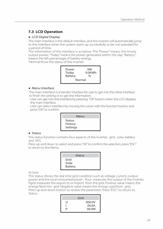
● LCD Digital DisplayThe main interface is the default interface, and the inverter will automatically jumpto this interface when the system starts up successfully or be not operated fora period of time.The information of the interface is as below. The “Power” means the timelyoutput power; “Today” means the power generated within the day. “Battery” means the left percentage of battery energy.“Normal”show the status of the inverter.
7.3 LCD Operation
Power 0WToday 0.0KWhBattery %
Normal
● Menu Interface The main interface is a transfer interface for user to get into the other interface to finish the setting or to get the information.- User can get into this interface by pressing “OK” button when the LCD displays the main interface.- User can select interface by moving the cursor with the function button, and press “OK” to confirm.
StatusHistorySettings
Menu
● StatusThe status function contains four aspects of the inverter, grid , solar, batteryand EPS.Press up and down to select and press “OK” to confirm the selection, press “ESC”to return to the Menu.
Grid Solar Battery
Status
A) Grid This status shows the real time grid condition such as voltage, current, outputpower and the local consumed power . Pout measures the output of the inverter,Pgrid measures the export to or import from the grid. Positive value means the energy feed into grid. Negative value means the energy used from grid.Press up and down button to review the parameter. Press “ESC” to return toStatus .
U 000.0VI 00.0AP 00.0W
Grid

Operation Method
40
B) Solar This status shows the real time PV condition of the system. The input voltage,current and power situation of each PV input.Press up and down button to review the parameter. Press “ESC” to return toStatus .
U1 360.0VI1 1.0AP1 360W
Solar
C) Charger This status shows the charger situation of the system. Include the battery voltage,charge or discharge current. Charge or discharge power, battery capacity andbattery temperature. “+” means in charging; “-” means in discharging. Press up and down button to review the parameter. Press “ESC” to return to Status.
U 54.0VI +1.0AP +54W
Charger
● HistoryThe history function contains three aspects of the information: inverter yield,charger yield and error log.Press up and down to select ,and press “OK” to confirm the selection, press “ESC”to return to the Menu.
Inverter Yield Charger Yield Error Logs
History
D) EPS EPS will only have data when the inverter is working in EPS mode, it will showthe real time data of the EPS output. As voltage, current, power, frequency. Press up and down button to review the parameter. Press “ESC” to return to Status.
EPSU 220VI 12AP 2640W

Operation Method
41
A) Inverter YieldThe inverter yield function contains the energy generated by today, yesterday,this month, last month and total. Press up and down button to review the parameter. Press “ESC” to return to History .
>Today: 00.0KWH
Inverter Yield
B) Charger YieldThe charger Yield function contains the energy generated from battery by today, yesterday, this month, last month and total.Press up and down button to review the parameter. Press “ESC” to return toHistory .
C) Error LogsThe Error logs contain the error information happened, Which can record for three items.Press up and down button to review the parameter. Press “ESC” to return toHistory .
>Today: 00.0KWH
Charger Yield
> No error
Error logs
● SettingsSetting function is used for setting the inverter for time, connection, battery,Ethernet, Grid and so on.Since this function will change the inverter’s parameter, the end user with the user password as”0000" have the limited authority to change the settings.We need installer password to do most of the professional settings.
Safety Date time Connection
Settings

B) SafetyUser can set safety standard according to different countries and grid tied stanndards.There are 19 standards for choice. (May change without notice)All parameters are shown below.
A) PasswordThe default password is “0000” for end user, Which only allow the user to reviewthe current setting and some easy settings . If professional change is needed , please contact with the distributor or factory for the installer password.
C) Date timeThis interface is for user to set the system date and time. Increase or decreasethe word by pressing up or down button. Press OK to confirm and alternate to thenext word. After all the words are confirmed. Press “OK” to enter the date and time.
2013 ->06 <-0610:19
Date time
Operation Method
42
Item
11
1
2
3
4
5
6
7
8
9
10
12
13
14
15
16
17
18
19
Country
VDE 0126
ARN 4015 German
AS 4777 Australia
G83/2 UK
C10_11 Belgium
OVE/ONORME 8001 AustriaEN 50438_NL Netherland
EN 50438_DK Danmark
CEB UK
CEI 0-21 Italy
VDE0126_Greece Greece
IEC61727_In India
Standard
NRS097_2_1
UTE_C15_712_Fr
German
South Africa
France
G59/3 UK
VFR_2014_Fr France
C15-712-is-60 France
C15-712-is-50 France
VDE 0126-Gr-is Greece
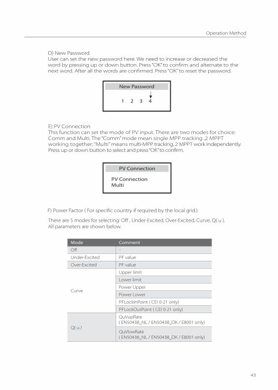
F) Power Factor ( For specific country if required by the local grid.)
There are 5 modes for selecting: Off , Under-Excited, Over-Excited, Curve, Q( u ).All parameters are shown below.
Mode Comment
Off
Under-Excited PF value
Over-Excited PF value
Curve
Upper limit
Lower limit
Power Upper
Power Lower
PFLockInPoint ( CEI 0-21 only)
PFLockOutPoint ( CEI 0-21 only)
Q( u )
QuVupRate
QuVlowRate
-
( EN50438_NL / EN50438_DK / E8001 only)
( EN50438_NL / EN50438_DK / E8001 only)
Operation Method
43
D) New PasswordUser can set the new password here. We need to increase or decreased theword by pressing up or down button. Press “OK” to confirm and alternate to thenext word. After all the words are confirmed. Press “OK” to reset the password.
1 2 3 4
New Password
E) PV ConnectionThis function can set the mode of PV input. There are two modes for choice:Comm and Multi. The “Comm” mode mean single MPP tracking ,2 MPPT working together; “Multi” means multi-MPP tracking, 2 MPPT work independently. Press up or down button to select and press “OK” to confirm.
PV ConnectionMulti
PV Connection

Reactive power control, Reactive standard curve cos φ = f(P)
0.50.2 1.0
0.95
0.95
cosφ
cap
activ
ein
duc
tive
f (P)
curve C
For VDE ARN 4105, curve cos φ = f(P) should refer to curve A. default values of setting are as shown in curve A.
For E 8001, curve cos φ = f(P) should refer to curve B. default values of setting are as shown in curve B.
For CEI 0-21, default value of PFLockInPoint is 1.05, when Vac > 1.05Vn, and Pac> 0.2 Pn, curve cos φ = f(P) should refer to curve C. Default value of PFLockOutPoint is 0.98, when Vac < 0.98 Vn, cos φ = f(P) will exit curve C.
Reactive power control, Reactive standard curve Q= f(V)
Q
V
Qmax
-Qmax
V2sV1s
V1iV2i
V2i=0.90Vn
V2s=1.10Vn
V1s=1.08Vn=QuVlowRate
V2i=0.92Vn=QuVlowRate
0.9
0.9
Upper limit
cap
activ
ein
duc
tive
f (P)
Lower limit
Power Lower
Power Upper
curve A
0.30.7
0.9
0.9
Upper limit
cap
activ
ein
duc
tive
f (P)
Lower limit
Power Lower
Power Upper
curve B
0.30.7
0.20.8
Operation Method
44
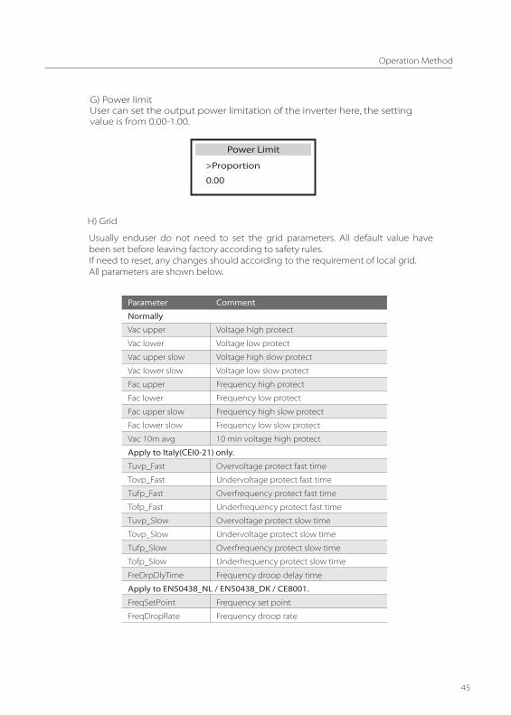
H) Grid
Usually enduser do not need to set the grid parameters. All default value have been set before leaving factory according to safety rules.If need to reset, any changes should according to the requirement of local grid.All parameters are shown below.
Parameter Comment
Normally
Vac upper Voltage high protect
Vac lower Voltage low protect
Vac upper slow Voltage high slow protect
Vac lower slow Voltage low slow protect
Fac upper Frequency high protect
Fac lower Frequency low protect
Fac upper slow Frequency high slow protect
Fac lower slow Frequency low slow protect
Vac 10m avg 10 min voltage high protect
Apply to Italy(CEI0-21) only.
Tuvp_Fast Overvoltage protect fast time
Tovp_Fast Undervoltage protect fast time
Tufp_Fast Overfrequency protect fast time
Tofp_Fast Underfrequency protect fast time
Tuvp_Slow
Tovp_Slow
Tufp_Slow
Tofp_Slow
FreDrpDlyTime
Overvoltage protect slow time
Undervoltage protect slow time
Overfrequency protect slow time
Underfrequency protect slow time
Frequency droop delay time
Apply to EN50438_NL / EN50438_DK / CE8001.
FreqSetPoint
FreqDropRate
Frequency set point
Frequency droop rate
Operation Method
45

J) Export controlWith this function the inverter can control the energy exported to the grid.There are user value and factory value.The factory value is default which can not be changed by user.The user value setting by installer must be less than the factory value. Press up and down button to select and press “OK” to con�rm.
Operation Method
46
I) Work modeThe default work mode of the inverter is Self Use mode. User can set the work modeas Self Use or Force Time Use here as describe in 3.1. For the Force Time Use. User can set 2 periods of the start and end time of charger or discharge. Also can select if charging from grid for each charging period.
>Mode Select
Force time use
Work Mode
> Charge Start time 1 08:00
Work Mode
>Charger period 1 Charge From Grid Disable
Work Mode
Charger start time1Charger end time1
The start time of the �rst charger period.
Charger start time2
Charger end time2
Discharger start time1
Discharger end time1
Discharger start time2
Discharger end time2
The end time of the �rst charger period.
The start time of the second charger period.
The end time of the second charger period.
The start time of the �rst discharger period.
The end time of the �rst discharger period.
The start time of the second discharger period.
The end time of the second discharger period.
Parameter Comment

For lead acid battery, when charging begins, it will enter constant votlage charging mode in order to accelerate charging speed. Thevalue can be set for 50-58V.
For lead acid battery, it will switch to �oat charging mode after exiting constant voltage charging mode. The value can be set for 50-58V
Charge Absorp Voltage
Charge Float Voltage
Only for lithium battery and its BMS is compatible with inverter’s protocol, the parameter”Min capacity”need to be set.
Operation Method
47
K) ChargerHere the user can set the parameters of charger ,the inverter is compatible with Lead acid and lithium batteries. Users can set the battery type, charge and discharge parameters,awaken mode here.Press up or down button to select and press“OK” to confirm. For the detailed parameters , please refer to below table.
>Battery type Lithium
Charger
>Min Capacity 20%
Charger
>Battery awaken
Charger
No
NOTE�!Please con�rm the Inverter setting for maximum charge/discharge current is within the range of battery rated charge/discharge current.

t
charge absorp volt
charge float volt
t
53.5
charge cut volt
Lithium BatteryLead Acid Battery
stage 1 stage 2 stage 3
54
V/A
56
voltage
current
V/A
Based on the different energy platforms between lithium battery and lead acid battery, , lead acid battery need to be set to 3 stages during charging, which is in order to increase its charging efficiency. In stage 1, it will be charged with constant current till the voltage rises to charge absorp volt to enter stage 2. In stage 2, it can be charged efficiently with constant voltage till charge current is more than 1A or time in this stage reaches 2 hours. Then it will enter stage 3 for �oating
Example:
Lithium Battery: usually the lithium will have communication with the inverter.when the BMS is connected all the charger setting will updated to the default value as below.
Lead acid battery : all the data need to be set as the suggestion from the battery Supplier. For default setting is as below.
Note:Installer can set the parameters manually .The parameters”Battery backup discharge Volt” need to be set in the EPS System page.
Charge absorp voltage:
Charge �oat voltage:
Charge Max current:
Discharger Max current:
Battery backup discharge Volt:
54V
47V
46V
50A
50A
54V
47V
46V
100A
100A
Discharge cut voltage:
56V 56V
Min capacity:
Charge cut voltage:
Charge Max current:
Discharger Max current:
Battery backup discharge Volt:
SK-BMU2500
53.5V
47V
46V
50A
50A
SK-BMU5000
53.5V
47V
46V
100A
100A
Discharge cut voltage:
20% 20%
Operation Method
48
SK-BMU2500 SK-BMU5000
Operation Method
49
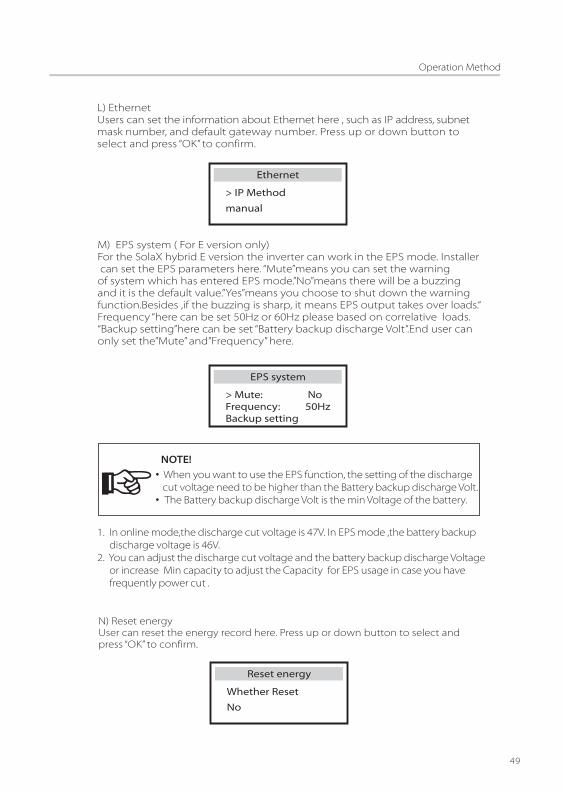
L) EthernetUsers can set the information about Ethernet here , such as IP address, subnetmask number, and default gateway number. Press up or down button to select and press “OK” to confirm.
> IP Methodmanual
Ethernet
M) EPS system ( For E version only)For the SolaX hybrid E version the inverter can work in the EPS mode. Installer can set the EPS parameters here. “Mute”means you can set the warning of system which has entered EPS mode.”No”means there will be a buzzing and it is the default value.”Yes”means you choose to shut down the warning function.Besides ,if the buzzing is sharp, it means EPS output takes over loads.“Frequency “here can be set 50Hz or 60Hz please based on correlative loads. “Backup setting”here can be set “Battery backup discharge Volt”.End user can only set the”Mute” and”Frequency” here.
> Mute: NoFrequency: 50HzBackup setting
EPS system
• When you want to use the EPS function, the setting of the discharge cut voltage need to be higher than the Battery backup discharge Volt.• The Battery backup discharge Volt is the min Voltage of the battery.
NOTE!
1. In online mode,the discharge cut voltage is 47V. In EPS mode ,the battery backup discharge voltage is 46V.2. You can adjust the discharge cut voltage and the battery backup discharge Voltage or increase Min capacity to adjust the Capacity for EPS usage in case you have frequently power cut .
N) Reset energyUser can reset the energy record here. Press up or down button to select andpress “OK” to confirm.
Whether ResetNo
Reset energy
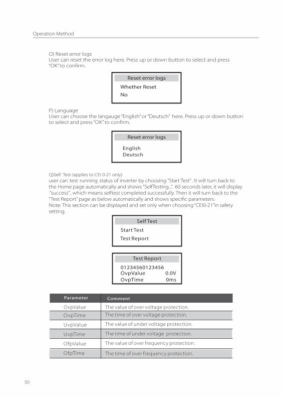
Q)Self Test (applies to CEI 0-21 only)user can test running status of inverter by choosing ”Start Test” . It will turn back to the Home page automatically and shows ”SelfTesting...”. 60 seconds later, it will display “success” , which means selftest completed successfully. Then it will turn back to the“Test Report” page as below automatically and shows speci�c parameters.Note: This section can be displayed and set only when choosing “CEI0-21"in safetysetting.
Start Test
Test Report
Test Report
OvpValue 0.0VOvpTime 0ms
01234560123456
OvpValue
OvpTime
UvpValue
UvpTime
OfpValue
OfpTime
The value of over voltage protection.The time of over voltage protection.
The value of under voltage protection.
The time of under voltage protection.
The value of over frequency protection.
The time of over frequency protection.
Operation Method
50
O) Reset error logsUser can reset the error log here. Press up or down button to select and press“OK” to confirm.
Whether ResetNo
Reset error logs
P) LanguageUser can choose the langauge “English” or “Deutsch” here. Press up or down buttonto select and press “OK” to confirm.

UfpValue
UfpTime
The value of under frequency protection.
The time of under frequency protection.
Ovp_AVG
Tovp_AVG
The average value of over volatge protection in 10 min.
The average time of over volatge protection in 10 min.
OfpVal2
OfpTime2
UfpVal2
UfpTime2
The value of over frequency protection in restrictive mode.
The time of over frequency protection in restrictive mode.
The value of under frequency protection in restrictive mode.
The time of under frequency protection in restrictive mode.
R) RelayControl RelayControl is an optional function which can control designated load inteligently by consuming the surplus energy when feed in power reachescertain value.For specific opreation, please refer to “ Load remote control installation guide”.
Operation Method
51
Troubleshooting
52
8.1 Trouble Shooting
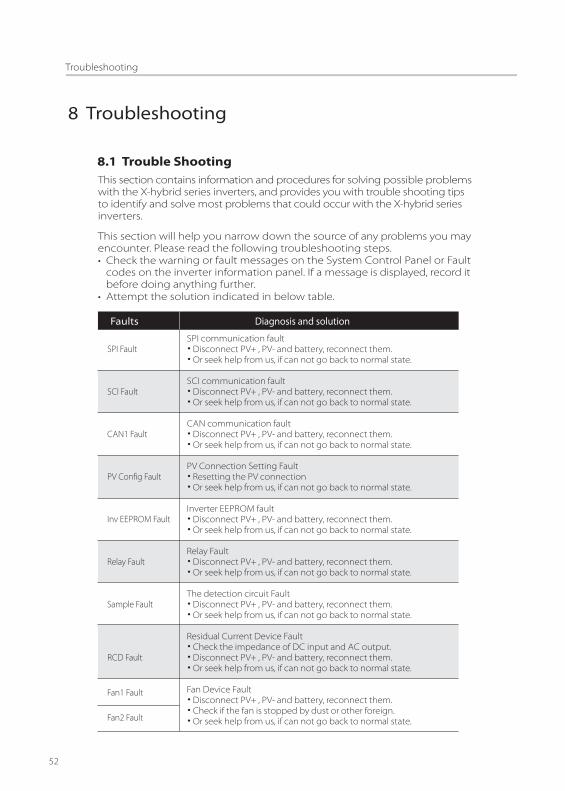
Faults
SPI Fault
SCI Fault
CAN1 Fault
PV Config Fault
Inv EEPROM Fault
Relay Fault
Sample Fault
RCD Fault
Fan1 Fault
Fan2 Fault
Diagnosis and solution
SPI communication fault• Disconnect PV+ , PV- and battery, reconnect them.• Or seek help from us, if can not go back to normal state.
SCI communication fault• Disconnect PV+ , PV- and battery, reconnect them.• Or seek help from us, if can not go back to normal state.
CAN communication fault• Disconnect PV+ , PV- and battery, reconnect them.• Or seek help from us, if can not go back to normal state.
PV Connection Setting Fault• Resetting the PV connection• Or seek help from us, if can not go back to normal state.
Inverter EEPROM fault• Disconnect PV+ , PV- and battery, reconnect them.• Or seek help from us, if can not go back to normal state.
Relay Fault • Disconnect PV+ , PV- and battery, reconnect them.• Or seek help from us, if can not go back to normal state.
The detection circuit Fault• Disconnect PV+ , PV- and battery, reconnect them.• Or seek help from us, if can not go back to normal state.
Residual Current Device Fault • Check the impedance of DC input and AC output.• Disconnect PV+ , PV- and battery, reconnect them.• Or seek help from us, if can not go back to normal state.
Fan Device Fault• Disconnect PV+ , PV- and battery, reconnect them.• Check if the fan is stopped by dust or other foreign.• Or seek help from us, if can not go back to normal state.
This section contains information and procedures for solving possible problemswith the X-hybrid series inverters, and provides you with trouble shooting tipsto identify and solve most problems that could occur with the X-hybrid seriesinverters.
This section will help you narrow down the source of any problems you mayencounter. Please read the following troubleshooting steps.• Check the warning or fault messages on the System Control Panel or Fault codes on the inverter information panel. If a message is displayed, record it before doing anything further.• Attempt the solution indicated in below table.
Troubleshooting
53
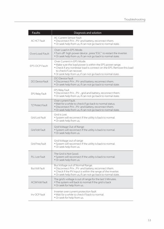
Faults Diagnosis and solution
AC HCT Fault
DCI Device Fault
TZ Protect Fault
Grid Lost Fault
Grid Volt Fault
Grid Freq Fault
PLL Lost Fault
Bus Volt Fault
AC5M Volt Fault
Inv OCP Fault
AC Current Sensor Fault• Disconnect PV+ , PV- and battery, reconnect them.• Or seek help from us, if can not go back to normal state.
DCI Device Fault• Disconnect PV+ , PV- and battery, reconnect them.• Or seek help from us, if can not go back to normal state.
Over current Fault.• Wait for a while to check if go back to normal status.• Disconnect PV+ , PV- and battery, reconnect them.• Or seek help from us, if can not go back to normal state.
Grid is Lost.• System will reconnect if the utility is back to normal. • Or seek help from us.
Grid Voltage Out of Range• System will reconnect if the utility is back to normal. • Or seek help from us.
Grid Voltage out of range• System will reconnect if the utility is back to normal. • Or seek help from us.
The Grid is Not Good.• System will reconnect if the utility is back to normal.• Or seek help from us.
Bus Voltage out of Normal Range.• Disconnect PV+ , PV- and battery, reconnect them.• Check if the PV input is within the range of the inverter.• Or seek help from us, if can not go back to normal state.
The grid's voltage is out of range for the last 5 Minutes.• The system will back to normal if the grid is back• Or seek for help from us.
Inverter over current protection fault• Wait for a while to check if back to normal.• Or seek for help from us.
OverLoad FaultOver Load in EPS Mode.• Turn off high power device , press “ESC” to restart the inverter.• Or seek help from us, if can not go back to normal state.
EPS OCP Fault
Over Current in EPS Mode.• Make sure the load power is within the EPS power range.• Check if any nonlinear load is connect on the EPS. Remove this load to check if can recover. • Or seek help from us, if can not go back to normal state.
EPS Relay FaultEPS Relay Fault• Disconnect PV+ , PV- , grid and battery, reconnect them.• Or seek help from us, if can not go back to normal state.
ƒ

Troubleshooting
54
Faults Diagnosis and solution
PV Volt Fault
AC10M Volt Fault
Isolation Fault
Temp Over Fault
Fan1 Speed Fault
Fan2 Speed Fault
C1 Can Fault
C1 Temp High
C1 FAN Fault
C1 TZ Fault
C1 EEPROM Fault
C1 HCT1 Fault
C1 Bus OVP
PV Voltage Fault• Check the output of the PV voltage.• Or seek for help from us.
The grid's Voltage is out of range for the last 10 minutes.• The system will back to normal if the grid is back• Or seek for help from us.
Isolation Fault• Check the connection of the inverter.• Or seek for help from us.
Temperature over the limitation• Check if the fan is running normally.• Check if the envirement temperature is over limitation.\• Or seek help from us.
Fan speed out of the normal range.• Check if the fan is stopped by dust or other foreign.• Or seek help from us, if can not go back to normal state.
The battery group's can communication fault.• Reconnect the charger communication cable.• Or seek help from us.
The battery charger is over temperature.• Check if the air ducting of the charger is blocked.• Improve the working environment or reduce the charging or discharging current.• Or ,Seek help from us.
The fan of the charger is broken.• Check if the fan is working normally.• Check if anything blocking the fan• Or, Seek help from us.
The protection of the charger fault.• Wait for a while to check if back to normal.• Or, Seek help from us.
The charger's EEPROM fault.• Wait for a while to check if back to normal.• Or, Seek for help from us.
The charger's current detection fault.• Reconnect the charger.• Or, Seek for help from us.
The Bus voltage of the charger over limit.• Wait for a while to check if back to normal.• Or, Seek for help from us.
C1 Temp LowThe charger is under temperature• Improve the working environment of the charger.• Or, Seek for help from us.
C1 HCT2 Fault

Troubleshooting
55
Faults Diagnosis and solution
C1 Boost OVPThe Boost voltage of the charger over limit.• Wait for a while to check if back to normal.• Or. Seek for help from us.
The battery voltage is over limit.• Wait for a while to check if back to normal.• Or, Seek for help from us.
The charger is over current protected.• Wait for a while to check if back to normal.• Or, Seek help from us.
The boost current of the charger is over limit.• Wait for a while to check if back to normal.• Or, Seek help from us.
C1 Bat OVP
C1 Charger OCP
C1 Boost OCP
CT FaultThe CT or the meter is not connected well. Check the connection of the CT or the meter. Or, Seek help from us.•
•
RC FaultDCI over current protection Fault.• Wait for a while to check if back to normal.• Or seek for help from us.
DCI OCP FaultDCI over current protection Fault.
• Or seek for help from us.
Other device FaultOther device fault.
• Or seek for help from us if can not back to normal.
• Wait for a while to check if back to normal.
• Turn off the PV, battery and grid , reconnect them.
SW OCP FaultOver current fault detected by software.• Turn off the PV, battery and grid , reconnect them.• Or seek for help from us if can not back to normal.
Dm9000 Fault Network DSP fault.• Turn off the PV, battery and grid , reconnect them.• Or seek for help from us if can not back to normal.
RTC Fault
RTC Fault • Turn off the PV, battery and grid , reconnect them.• Or seek for help from us if can not back to normal.
Mgr EEPROM Fault
Manager EEPROM Fault.
• Turn off the PV, battery and grid , reconnect them.• Or seek for help from us if can not back to normal.
Troubleshooting
56
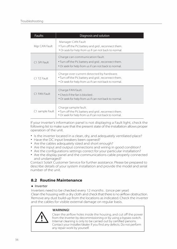
Faults Diagnosis and solution
Mgr CAN FaultManager CAN Fault• Turn off the PV, battery and grid , reconnect them.• Or seek for help from us if can not back to normal.
C1 SPI Fault
C1 TZ Fault
C1 FAN Fault
C1 sample Fault
Charge can communication fault.
• Turn off the PV, battery and grid , reconnect them.
• Or seek for help from us if can not back to normal.
Charge over current detected by hardware.• Turn off the PV, battery and grid , reconnect them.• Or seek for help from us if can not back to normal.
Charge FAN fault.
• Check if the fan is blocked . • Or seek for help from us if can not back to normal.
Charge sample fault.• Turn off the PV, battery and grid , reconnect them.• Or seek for help from us if can not back to normal.
If your inverter's information panel is not displaying a Fault light, check thefollowing list to make sure that the present state of the installation allows properoperation of the unit.
8.2 Routine Maintenance● InverterInverters need to be checked every 12 months . (once per year) Clean the housing with a dry cloth and check that there is no airflow obstruction. Remove any dust build-up from the locations as indicated. Check the inverterand the cables for visible external damage on regular basis.
Clean the airflow holes inside the housing, and cut off the powerfrom the inverter by decommissioning or by using a bypass switch.Internal cleaning is only to be carried out by certified persons. Contact your installer/dealer if you find any defects. Do not performany repair work by yourself.
WARNING!
• Is the inverter located in a clean, dry, and adequately ventilated place?• Have the DC input breakers been opened? • Are the cables adequately sized and short enough?• Are the input and output connections and wiring in good condition?• Are the configurations settings correct for your particular installation?• Are the display panel and the communications cable properly connected and undamaged?Contact SolaX Customer Service for further assistance. Please be prepared todescribe details of your system installation and provide the model and serialnumber of the unit.

Decommissioning
57
The chapter is only for reference. The exact maintenance shouldbe according to the guide provided by the battery manufacture.
NOTE�!
• Disconnect the inverter from DC input and AC output.• Disconnect battery wiring. • Wait for 5 minutes for de-energizing.• Disconnect communication and optional connection wiring.• Remove the inverter from the bracket.
9.1 Dismantling the Inverter
9 Decommissioning
If possible, please pack the inverter with the original packaging.If it is no longer available, you can also use an equivalent carton that meetsthe following requirements.• Suitable for loads more than 25 kg.• With handle.• Can be fully closed.
9.2 Packaging
Store the inverter in dry place where ambient temperatures are always between-20 °C - +60 °C.
9.3 Storage
When the inverter or other related components need to be disposed. Haveit carried out according to local waste handling regulations. Please be sure todeliver wasted inverters and packing materials to certain site, where can assistrelevant department to dispose and recycle.
9.4 Disposal
● BatteryThe X-hybrid series inverter is compatible with both lead-acid and lithium battery. Either type of the battery needs to be maintained every month /quarter/ yearaccording to different types and requirement of the battery. If the capacity of the battery decreased to lower than 80% of the rated capacity,the battery should be replaced.


614.00036.05