6182 defects and nonstoichiometry - school of chemistry...
TRANSCRIPT

Defects and nonstoichiometry
� Simple intrinsic point defects� The thermodynamics of defect formation� Extrinsic defects� Defects in nonstoichiometric materials� Defect clustering� Solid solutions� Extended defects
– CS planes and shear structures
Defects in crystals
� It is not possible to make crystals that are prefect in every respect– some are more perfect than others
� It takes energy to create defects in crystals
� The presence of defects increases the entropy of the crystal– above absolute zero always expect some intrinsic
defects
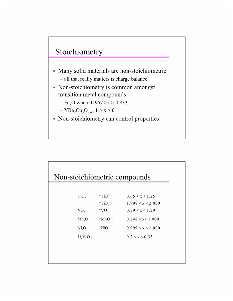
Stoichiometry
� Many solid materials are non-stoichiometric– all that really matters is charge balance
� Non-stoichiometry is common amongst transition metal compounds– FexO where 0.957 >x > 0.833– YBa2Cu3O7-x, 1 > x > 0
� Non-stoichiometry can control properties
Non-stoichiometric compounds
TiO x “TiO ” 0.65 < x < 1.25
“TiO 2” 1.998 < x < 2.000
VO x “VO” 0.79 < x < 1.29
MnxO “MnO ” 0.848 < x< 1.000
NixO “NiO” 0.999 < x < 1.000
LixV2O 5 0.2 < x < 0.33
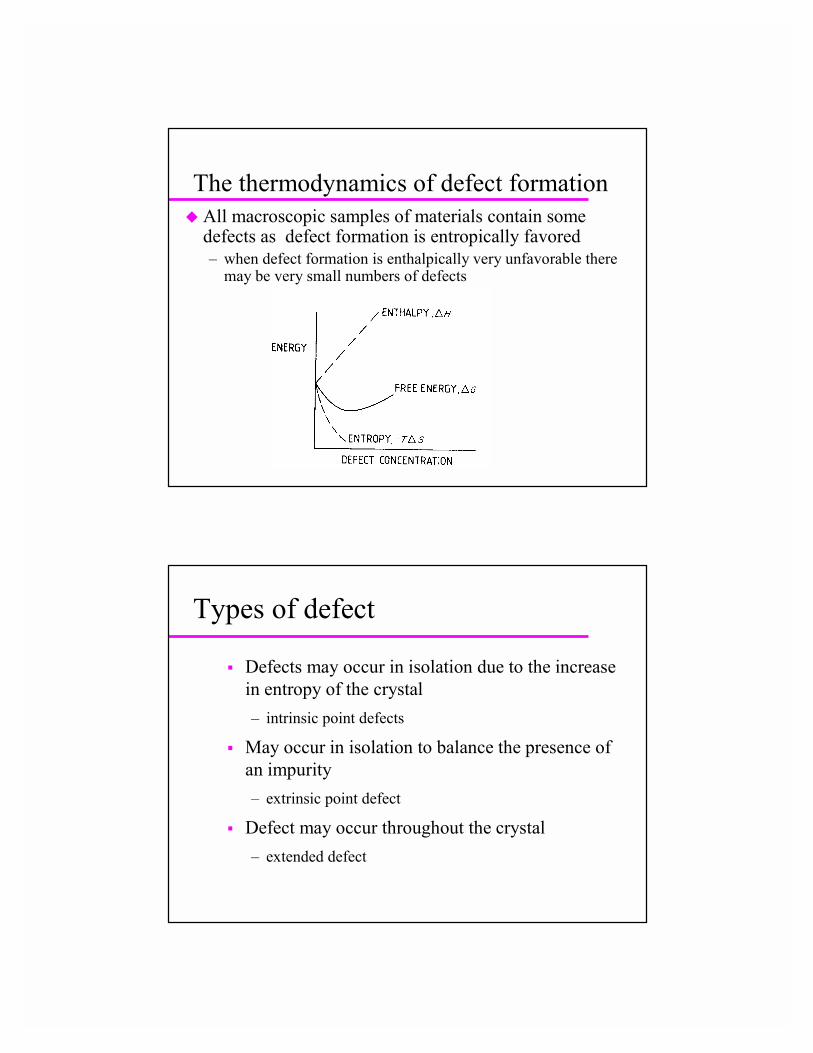
The thermodynamics of defect formation� All macroscopic samples of materials contain some
defects as defect formation is entropically favored– when defect formation is enthalpically very unfavorable there
may be very small numbers of defects
Types of defect
� Defects may occur in isolation due to the increase in entropy of the crystal– intrinsic point defects
� May occur in isolation to balance the presence of an impurity– extrinsic point defect
� Defect may occur throughout the crystal– extended defect

Intrinsic point defects
� Two common types of intrinsic point defect– Schottky and Frenkel
� A Schottky defect consists of charge balancingcation and anion vacancies– Found in NaCl
� A Frenkel defect is a charge balancing interstitial and vacancy– can have cation or anion Frenkel defects
Schottky and Frenkel defects
Shottky defect in NaCl- both cation and anion are missing from
their regular lattice sites-at room temp on 1 in 1015 sites are vacant in NaCl-200 kJmol-1 creation energy
Cation Frenkel defect in AgCl-cation is displaced from regular lattice
site onto interstitial site- 130 kJ mol-1 creation energy

Frenkel defects
� Frenkel defects may occur on either the anion orcation sublattice
� Cation Frenkel defects are more common than anion defects– cations are smaller than anions and hence easier to
accommodate in interstitial positions� Fluorite structures (CaF2, SrF2, ZrO2, UO2) are
good at accommodating anion Frenkel defects
Kroger-Vink notation for defects� Defect is denoted by symbol of atom involved or by V if it is a vacancy� Superscript • indicates a net charge of +1, superscript ‘ indicates a net
charge of –1. Superscript x indicates no net charge� Subscript indicates nature of site in crystal lattice, s for surface, I for
interstitial, element symbol for normal lattice site� Examples:
– V’Na sodium ion vacancy net charge –1– V•
Cl chloride ion vacancy net charge +1– Nax
Na, ClxCl Na and Cl on their normal lattice sites
– Cd•Na cadmium on Na site net charge +1
– Ag•i silver on interstitial site net charge +1
– F’i fluoride on interstitial site net charge -1
Estimation of defect concentration
� It is possible to calculate the equilibrium concentration of defects in a solid using statistical mechanics
� ns ~ N exp(-∆HS / 2RT)� nF ~ (NNi)1/2 exp(-∆HF/2RT)� Defect concentration depends upon the energy
needed to form a defect and the temperature
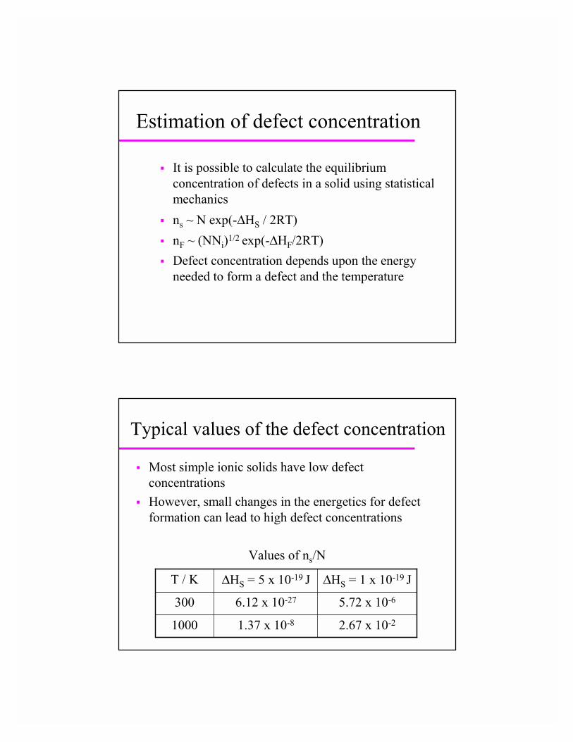
Typical values of the defect concentration
� Most simple ionic solids have low defect concentrations
� However, small changes in the energetics for defect formation can lead to high defect concentrations
2.67 x 10-21.37 x 10-81000
5.72 x 10-66.12 x 10-27300
∆HS = 1 x 10-19 J∆HS = 5 x 10-19 JT / K
Values of ns/N
Defects in AgCl
� Ag+ + Vi � Agi+ + VAg
� K = [Agi+][VAg] / [Ag+][Vi]
� Let N be the number of lattice sites and Ni the number of interstitial sites– Ni = [VAg] = [Agi
+]– [Ag+] = N - Ni
� [Vi] = αN – number of interstitials is simply related to number of
lattice sites for most materials
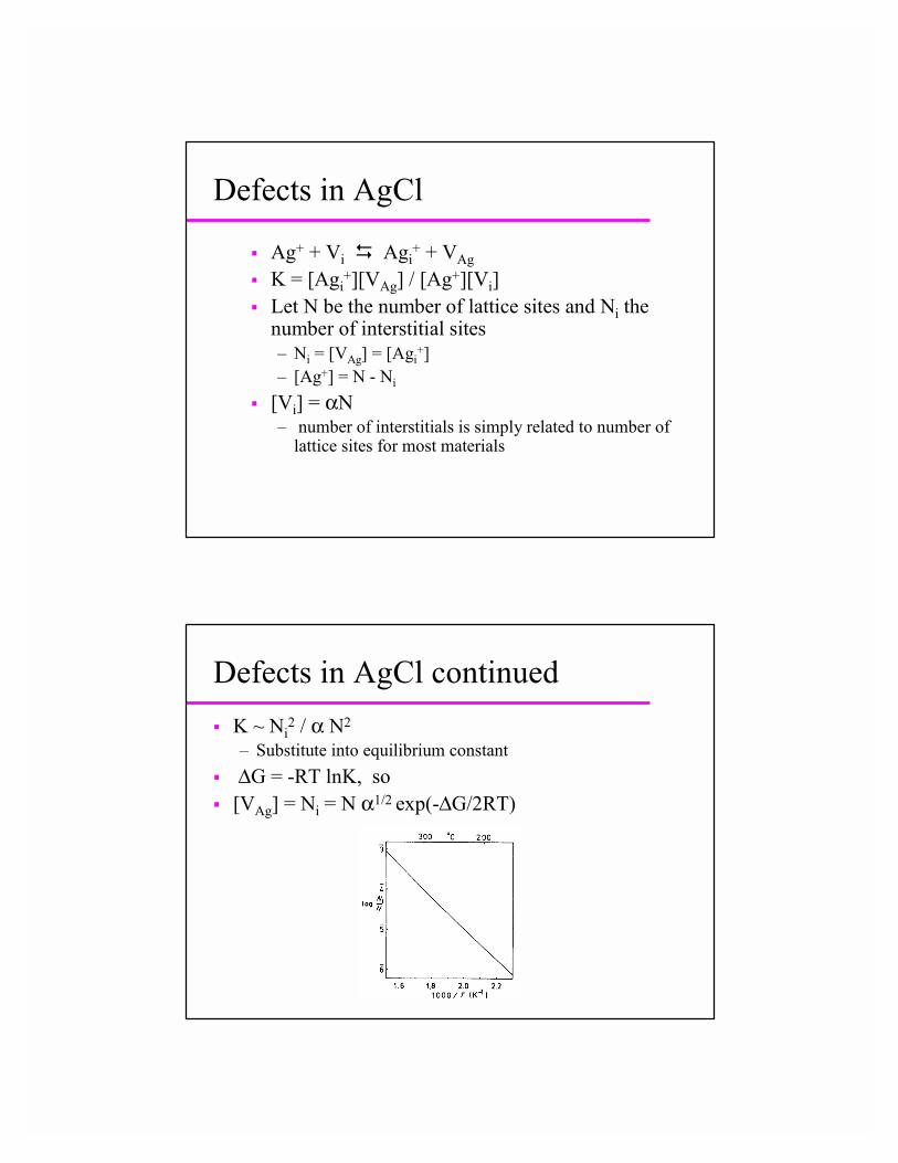
Defects in AgCl continued� K ~ Ni
2 / α N2
– Substitute into equilibrium constant� ∆G = -RT lnK, so� [VAg] = Ni = N α1/2 exp(-∆G/2RT)

∆Hf for defects
Color centers
� Electrons trapped in vacant sites give rise to colored materials– color centers– color arises due to transitions between electron in a box
levels� Trapped electrons can be produced by
– irradiation of the sample– treatment with an electron donor like sodium or
potassium vapor

F, H and V centers
F Center – electron trapped in anion vacancyExample of color center as trapped electron leads to absorption in visible
H Center – interstitial Cl atom bonds to lattice Cl-
V Center – electron removedfrom lattice anion site, resulting Cl atom pairs with neighboring Cl-
� Irradiation can lead to defects where an electron has bee lost or added� Treatment with alkali metal vapor can lead to excess electrons in material
Imaging plates
� Color centers are useful in medical X-rays using BaFBr:Eu2+ phosphors
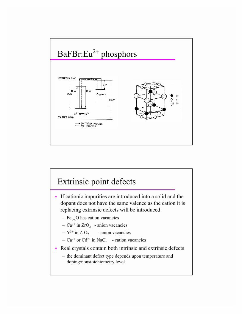
BaFBr:Eu2+ phosphors
Extrinsic point defects� If cationic impurities are introduced into a solid and the
dopant does not have the same valence as the cation it is replacing extrinsic defects will be introduced– Fe1-xO has cation vacancies– Ca2+ in ZrO2 - anion vacancies– Y3+ in ZrO2 - anion vacancies– Ca2+ or Cd2+ in NaCl - cation vacancies
� Real crystals contain both intrinsic and extrinsic defects– the dominant defect type depends upon temperature and
doping/nonstoichiometry level

Defect clusters and aggregates
� Point defects interact and effect the structure around them– This may lead to clustering
� Even in something as simple as NaCl, cation and anion vacancies tend to pair up as they are electrostatically attracted to one another
Nonstoichiometric 3d oxides

FeO
� Wustite is a very well studied example of anonstoichiometric compound
� The compound “FeO” is not stable
� The stoichiometry is always Fe1-xO
The iron oxygen phase diagram

The nature of the defects in “FeO”
� Density measurements confirm that thenonstoichiometry is incorporated by having vacant iron sites
� There is Fe(III) present to charge compensate the system
The defect structure of “FeO”
� The defect structure is more complicated than random iron vacancies and Fe(III)

Koch clusters in Fe1-xO
The Fluorite structure

Defect clusters in UO2+x
� Excess oxygen is incorporated in interstitial sites– This leads to displacement
of oxygens from normal sites
– Arrangement of defects is similar to structure of U4O9
» Can view defects as forming clusters of U4O9 in UO2matrix
The defect structure of TiO
� “TiO” spans the composition range TiO0.65 -TiO1.25
� The stoichiometric phase TiO has many vacancies– At high temperatures the vacancies are disordered– At low temperatures the Ti and O vacancies exist in an
ordered array
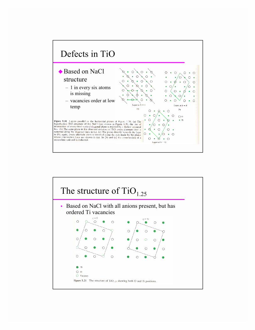
Defects in TiO
�Based on NaCl structure– 1 in every six atoms
is missing– vacancies order at low
temp
The structure of TiO1.25
� Based on NaCl with all anions present, but has ordered Ti vacancies
Order disorder
� Many materials show temperature dependent ordering phenomena
� Spinels frequently show temperature dependent ordering– Mgtet[Al2]octO4 (normal) and Mgtet[MgTi]octO4
(inverted) but other compositions may be partially inverted and the degree of inversion may depend on synthesis temperature
Substitutional solid solutions� In many compounds it is possible to replace a metal
atom or ion with another element that has similar size and bonding requirements– In metal alloy can replace metal atom with another element
that is within 15% size– Can get complete solid solution formation between Al2O3
and Cr2O3 – Al2-xCrxO3– Exstensive solid solution formation is favored by high
temperatures due to the disorder associated with the solid solution
Criteria for solid solution formation� Typically, for an ionic solid the ion size difference
should be less than 15-20% to get complete solid solution formation– > 30% size difference usually precludes solid solution
formation� End member of solid solution should hve same
structure if complete solid solutions is to form– Zn2SiO4 and Mg2SiO4 have different metal coordination
» So Zn2-xMgxSiO4 and Mg2-xZnxSiO4 have different structures
Interstitial solid solutions
�Some solid solutions involve inserting atoms into interstitial sites in a parent structure– PdHx 0 < x < 0.7 - hydrogen occupies
interstitial sites in fcc Pd – Carbon in interstitial sites of fcc Fe
Aliovalent substitution� If you replace an ion by one with a different
oxidation state (aliovalent substitution) there has to be a charge compensation mechanism
� Cation vacancies– Dope calcium into NaCl – Na1-2xCaxVxCl– Replacement of Mg2+ by Al3+ in spinel
» [Mg1-3xVxAl2x]tet[Al2]octO4
– Oxidation of NiO» Ni2+
1-3xVxNi3+2xO
Aliovalent substitution� Interstitial anions
– Not common due to limited size of interstitial sites but occurs for fluorite structure
» Ca1-xYxF2+x
» U4+1-xU6+
xO2+x
� Anion vacancies– Important in ionic conductors
» Zr1-xCaxO2-x 0.1 < x < 0.2
� Interstitial cations– Lix(Si1-xAlx)O2 stuffed quartz structure (0 < x < 0.5)
Characterizing solid solutions�Can determine if solid solution forms by
measuring lattice constants of material using x-ray diffraction– Lattice constants typically vary linearly with solid
solution composition» Vegard’s law
�Can work our mechanism of solid solution formation with the aid of density determination
Magneli phases
� The oxides of metals such as W, Mo and Ti display a wide range of compositions
– WO3-x, MO3-x, TiO2-x
� Magneli realized that these compounds were best represented as homologous series of phases rather than solid solutions
– TinO2n-1, MonO3n-1 etc

Crystallographic shear structures
� The homologous series can be formed by incorporating crystallographic shear planes into the structures– these are extended defects
� The shear planes change the stoichiometry of the material– at the CS plane may have face sharing rather than edge
sharing or edge sharing rather than corner sharing� Can get shear planes in 2 or 3-D leading to
– slab structures and block structures
Molybdenum and tungsten oxides
� A wide variety of tungsten and molybdenum oxides are known
� Many of them belong to homologous series– MnO3n-1 or MnO3n-2
– for example, Mo4O11, Mo5O14 and Mo6O17
Defects in molybdenum and tungsten oxides
� Why are there so many different oxides?
� The parent oxide WO3 has a ReO3 structure at high temperature
� All of these different stoichiometry oxides can be derived from WO3 by incorporating an ordered array of planar defects
– crystallographic shear planes
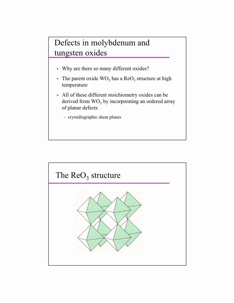
The ReO3 structure

The incorporation of a shear plane
Homologous series� Each member of the homologous series has a
different repeat distance between shear planes� Consider W11O32

Block structures
�Crystallographic shear planes running in two directions can lead to double shear or block structures– W4N26O77 consists
of 4 x 4 and 3 x4 blocks
Tungsten bronzes
� MxWO3– M is an alkali metal or alkaline earth or H
� They can be prepared by– electrocrystallization of melts– treatment of WO3 with alkali metal sources– hydrogen spillover
� There are a variety of possible crystal structures� Are used as bronze pigments

The structures of tungsten bronzes
� NaxWO3 - often ReO3 based� KxWO3 - 0.19 < x < 0.33 from reaction of K with
WO3 is hexagonal– potassium is bigger than sodium and needs a larger site
� KxWO3 - x < 0.19 regular intergrowth structure� Tetragonal bronzes are known for Na and K
Tungsten bronze structure types
Tetragonal tungsten bronze
Hexagonal tungsten bronze

Intergrowths
� It is possible to combine slabs of simple structures together to build up a solid
� If the slabs grow together in an order array you have an ordered intergrowth– new structure type if order is long range
� If slabs are randomly stacked together you have a random intergrowth
Intergrowth tungsten bronzes
Double rows hexagonal structure intergrown with ReO3 structure
Single rows hexagonal structure intergrown with ReO3 structure
� Hexagonal KxWO3 stable for 0.19 < x 0.33, lower values of x can be accommodated by intergrowingwith ReO3 type WO3
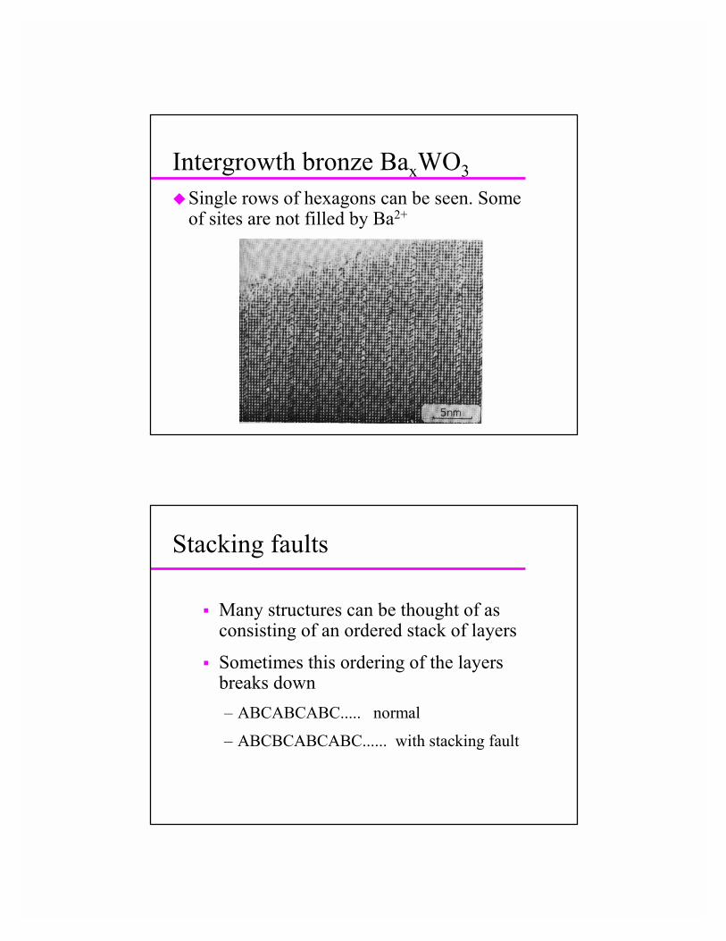
Intergrowth bronze BaxWO3�Single rows of hexagons can be seen. Some
of sites are not filled by Ba2+
Stacking faults
� Many structures can be thought of as consisting of an ordered stack of layers
� Sometimes this ordering of the layers breaks down – ABCABCABC..... normal
– ABCBCABCABC...... with stacking fault
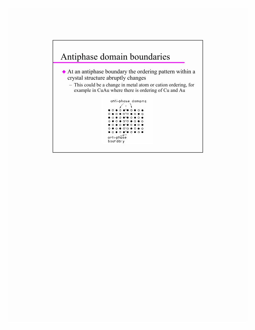
Antiphase domain boundaries� At an antiphase boundary the ordering pattern within a
crystal structure abruptly changes– This could be a change in metal atom or cation ordering, for
example in CuAu where there is ordering of Cu and Au