6.20 valve types: pinch valves - freetwanclik.free.fr/electricity/iepopdf/1081ch6_20.pdf · 500 400...
TRANSCRIPT
1323
6.20 Valve Types: Pinch Valves
C. S. BEARD (1975) J. B. ARANT (1985) B. G. LIPTÁK (1995)
J. B. ARANT, D. GARDELLIN, B. G. LIPTÁK (2005)
Applications: Abrasives, minerals in suspensions, hydraulically transported solids, slurries, vis-cous, or food industry products
Sizes: Generally 1 to 24 in. (25 mm to 0.61 m); special units from 0.1 to 72 in. (2.5 mmto 1.8 m)
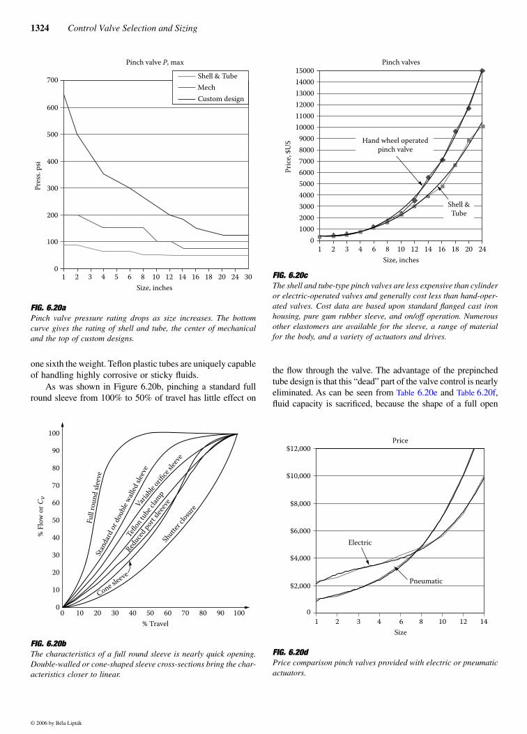
Design Pressures: Generally up to ANSI Class 150, with special units available with up to ANSIClass 300 ratings. See Figure 6.20a
Maximum Pressure Drop: Generally about 10 to 200 psid (69 to 138 kPa)
Design Temperatures: −20° to 350°F (−29° to 204°C)
Materials of Construction: Sleeve materials: Buna-N, Chlorobutyl, EPDM, Hypalon, Neoprene, PGR, Poly-urethane, Teflon, VitonBodies: Aluminum, cast grey iron, cast ductile iron, cast steel, stainless steel,Polyamide blend plastic
Characteristics: For the characteristics of reduced port and Clarkson pinch valves, refer to Figures6.20v and 6.20w; for others, refer to Figure 6.20b
Costs: See Figure 6.20c
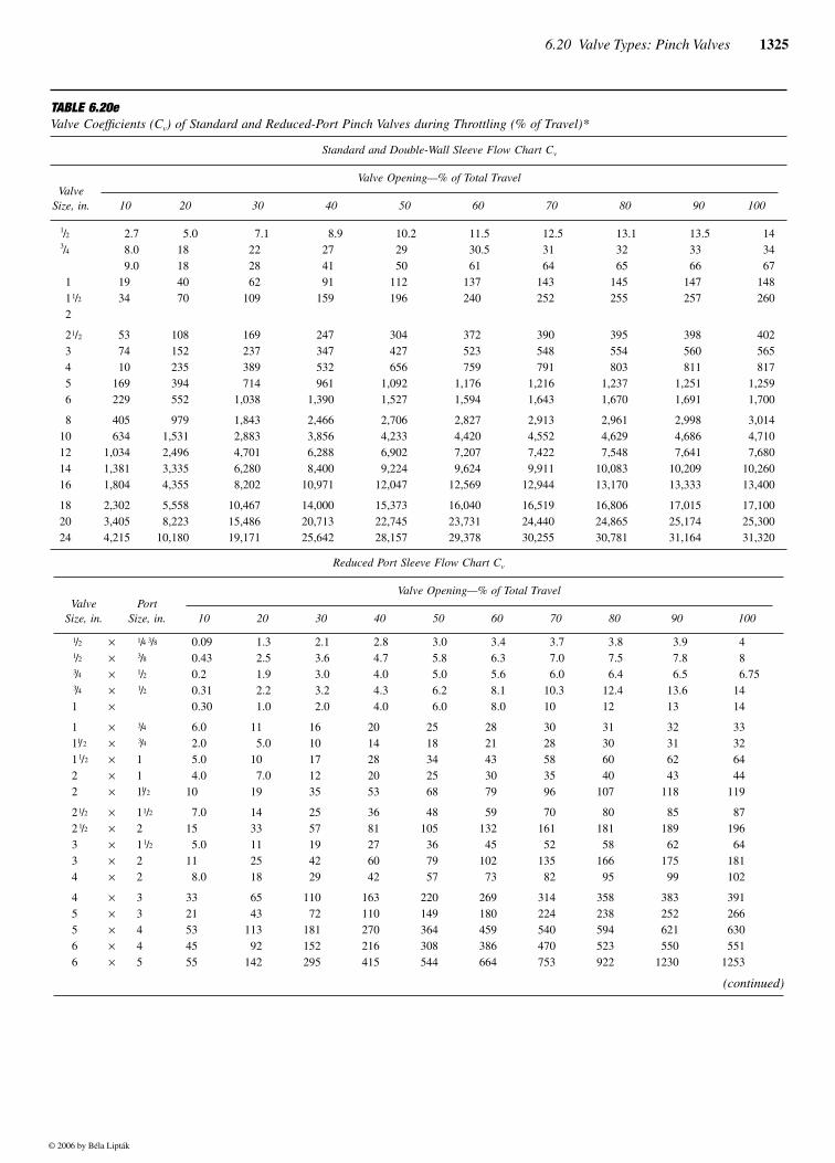
Capacity: Cv = 60 d2 for full-ported pinch valves and Cv = 20 d2 for reduced-ported pinchvalves; see Tables 6.20e and 6.20f
Rangeability: From 5:1 to 10:1
Leakage: Generally ANSI Class IV or Class V (see Table 6.1gg in Section 6.1for definitions)
Partial List of Suppliers: Clarkson Co. (www.tycovalves.com)Elasto-Valve Rubber Products Inc. (www.evrproducts.com)Ever-Flex (www.ever-flax.net)Larox (Finland–USA) (www.larox.fi)Onyx Valve Co. (www.onyxvalve.com)Red Valve Co. (www.redvalve.com)Richway Industries (www.richwayind.com)
INTRODUCTION
These valves are called either pinch or clamp valves, depend-ing upon the configuration of the flexible tube and on themeans used to compress the tube. The compression can bedone by mechanical clamping mechanisms or by externalpneumatic or hydraulic power within a metal jacket enclosure.Pinch valves have been improved due to introduction of plastictubes, elastomers, and reinforcing fabrics.
Tubes can be fabricated from pure gum rubber or froma variety of rubber-like elastomers such as Buna-N, butyl,neoprene, Nordel, hypalon, Viton, silicone, polyurethane,polypropylene, white butyl, and odorless and tasteless whiteneoprene. The latter two materials are often used in the foodand allied industries. Reinforcing fabrics may include someof the materials used in automobile tire fabrication, such ascotton duck, rayon, nylon, fiberglass, and Kevlar®, which isa new arimid polymer material that is as strong as steel at
X
Mechanicalpinch valve
Pneumaticpinch valve
FY
Flow sheet symbols
© 2006 by Béla Lipták
1324 Control Valve Selection and Sizing
one sixth the weight. Teflon plastic tubes are uniquely capableof handling highly corrosive or sticky fluids.
As was shown in Figure 6.20b, pinching a standard fullround sleeve from 100% to 50% of travel has little effect on
the flow through the valve. The advantage of the prepinchedtube design is that this “dead” part of the valve control is nearlyeliminated. As can be seen from Table 6.20e and Table 6.20f,fluid capacity is sacrificed, because the shape of a full open
FIG. 6.20a Pinch valve pressure rating drops as size increases. The bottomcurve gives the rating of shell and tube, the center of mechanicaland the top of custom designs.
FIG. 6.20b The characteristics of a full round sleeve is nearly quick opening.Double-walled or cone-shaped sleeve cross-sections bring the char-acteristics closer to linear.
1 6 8 10 12 14 16 18 20 24 302 3 4 5Size, inches
700
600
500
400
300
200
100
0
Pres
s. ps
i
Shell & TubeMechCustom design
Pinch valve P, max
% Fl
ow o
r Cv
100
0
10
20
30
40
50
60
70
80
90
0 10 20 30 40 50 60 70 80 90 100
Full
roun
d sle
eve
Stan
dard
or do
uble
walle
d slee
veVari
able
orifice
sleev
e
Teflo
n tub
e clam
p
Reduc
ed po
rt sle
eeve
Cone sleeve
Shutte
r clos
ure
% Travel
FIG. 6.20c The shell and tube-type pinch valves are less expensive than cylinderor electric-operated valves and generally cost less than hand-oper-ated valves. Cost data are based upon standard flanged cast ironhousing, pure gum rubber sleeve, and on/off operation. Numerousother elastomers are available for the sleeve, a range of materialfor the body, and a variety of actuators and drives.
FIG. 6.20d Price comparison pinch valves provided with electric or pneumaticactuators.
0100020003000400050006000700080009000
100001100012000130001400015000
1 2 3 4 6 8 10 12 14 16 18 20 24Size, inches
Pric
e, $U
S
Pinch valves
Hand wheel operatedpinch valve
Shell &Tube
Price
1 2 3 4 6 8 10 12 14Size
Electric
$2,000
0
$4,000
$6,000
$8,000
$10,000
$12,000
Pneumatic
© 2006 by Béla Lipták
6.20 Valve Types: Pinch Valves 1325
TABLE 6.20e Valve Coefficients (Cv) of Standard and Reduced-Port Pinch Valves during Throttling (% of Travel)*
Standard and Double-Wall Sleeve Flow Chart Cv
ValveSize, in.
Valve Opening—% of Total Travel
10 20 30 40 50 60 70 80 90 100
1/23/4
1 11/2
2
2.78.09.0
1934
5.0 18 18 40 70
7.1 22 28 62 109
8.9 27 41 91 159
10.2 29 50 112 196
11.5 30.5 61 137 240
12.5 31 64 143 252
13.1 32 65 145 255
13.5 33 66 147 257
14 34 67 148 260
21/2
3 4 5 6
537410
169229
108 152 235 394 552
169 237 389 714 1,038
247 347 532 961 1,390
304 427 656 1,092 1,527
372 523 759 1,176 1,594
390 548 791 1,216 1,643
395 554 803 1,237 1,670
398 560 811 1,251 1,691
402 565 817 1,259 1,700
810121416
405634
1,0341,3811,804
979 1,531 2,496 3,335 4,355
1,843 2,883 4,701 6,280 8,202
2,466 3,856 6,288 8,40010,971
2,706 4,233 6,902 9,22412,047
2,827 4,420 7,207 9,62412,569
2,913 4,552 7,422 9,91112,944
2,961 4,629 7,54810,08313,170
2,998 4,686 7,64110,20913,333
3,014 4,710 7,68010,26013,400
182024
2,3023,4054,215
5,558 8,22310,180
10,46715,48619,171
14,00020,71325,642
15,37322,74528,157
16,04023,73129,378
16,51924,44030,255
16,80624,86530,781
17,01525,17431,164
17,10025,30031,320
Reduced Port Sleeve Flow Chart Cv
ValveSize, in.
PortSize, in.
Valve Opening—% of Total Travel
10 20 30 40 50 60 70 80 90 100
1/21/23/43/4
1
×××××
1/4 3/83/81/21/2
0.09 0.43 0.2 0.31 0.30
1.3 2.5 1.9 2.2 1.0
2.1 3.6 3.0 3.2 2.0
2.8 4.7 4.0 4.3 4.0
3.0 5.8 5.0 6.2 6.0
3.4 6.3 5.6 8.1 8.0
3.7 7.0 6.0 10.3 10
3.8 7.5 6.4 12.4 12
3.9 7.8 6.5 13.6 13
4 8 6.75 14 14
111/2
11/2
22
×××××
3/43/4
1111/2
6.0 2.0 5.0 4.010
11 5.0 10 7.0 19
16 10 17 12 35
20 14 28 20 53
25 18 34 25 68
28 21 43 30 79
30 28 58 35 96
31 30 60 40107
32 31 62 43 118
33 32 64 44 119
21/2
21/2
334
×××××
11/2
211/2
22
7.015 5.011 8.0
14 33 11 25 18
25 57 19 42 29
36 81 27 60 42
48105 36 79 57
59132 45102 73
70161 52135 82
80181 58166 95
85 189 62 175 99
87 196 64 181 102
45566
×××××
33445
3321534555
65 43113 92142
110 72181152295
163110270216415
220149364308544
269180459386664
314224540470753
358238594523922
383 252 621 5501230
391 266 630 5511253
(continued)
© 2006 by Béla Lipták
1326 Control Valve Selection and Sizing
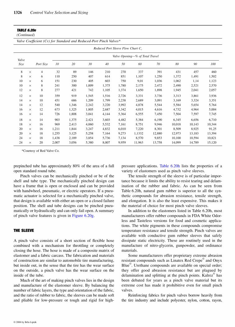
prepinched tube has approximately 80% of the area of a fullopen standard round tube.
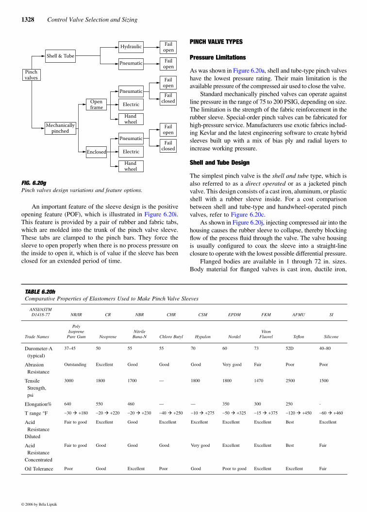
Pinch valves can be mechanically pinched or be of theshell and tube type. The mechanically pinched design canhave a frame that is open or enclosed and can be providedwith handwheel, pneumatic, or electric operators. If a pneu-matic actuator is selected for a mechanically pinched valve,that design is available with either an open or a closed failureposition. The shell and tube designs can be pinched pneu-matically or hydraulically and can only fail open. A summaryof pinch valve features is given in Figure 6.20g.
THE SLEEVE
A pinch valve consists of a short section of flexible hosecombined with a mechanism for throttling or completelyclosing the hose. The hose is made of a composite matrix ofelastomer and a fabric carcass. The fabrication and materialsof construction are similar to automobile tire manufacturing,but inside out, in the sense that the tire has the wear surfaceon the outside, a pinch valve has the wear surface on theinside of the tube.
Much of the art of making pinch valves lies in the designand manufacture of the elastomer sleeve. By balancing thenumber of fabric layers, the type and orientation of the fabric,and the ratio of rubber to fabric, the sleeves can be made softand pliable for low-pressure or tough and rigid for high-
pressure applications. Table 6.20h lists the properties of avariety of elastomers used as pinch valve sleeves.
The tensile strength of the sleeve is of particular impor-tance because it limits the ability to resist tearing and delam-ination of the rubber and fabric. As can be seen fromTable 6.20h, natural gum rubber is superior to all the syn-thetic compounds for abrasion resistance, tensile strength,and elongation. It is also the least expensive. This makes itthe material of choice for most pinch valve sleeves.
In addition to the elastomers listed in Table 6.20h, mostmanufacturers offer rubber compounds in FDA White Odor-less and Tasteless versions for food and cosmetic applica-tions. The white pigments in these compounds compromisetemperature resistance and tensile strength. Pinch valves areavailable with conductive gum rubber sleeves that safelydissipate static electricity. These are routinely used in themanufacture of nitro-glycerin, gunpowder, and ordinancematerials.
Some manufacturers offer proprietary extreme abrasionresistant compounds such as Linatex Red Crepe© and OnyxBlue©. Urethane compounds are available on special order;they offer good abrasion resistance but are plagued bydelamination and splitting at the pinch points. Kalrez© hasbeen debated for years as a pinch valve material but itsextreme cost has made it prohibitive even for small pinchvalves.
Reinforcing fabrics for pinch valves borrow heavily fromthe tire industry and include polyester, nylon, cotton, rayon,
TABLE 6.20e (Continued)
Valve Coefficient (Cv) for Standard and Reduced-Port Pinch Valves*
Reduced Port Sleeve Flow Chart Cv
ValveSize Port Size
Valve Opening—% of Total Travel
10 20 30 40 50 60 70 80 90 100
8 8101012
×××××
4 6 6 8 8
32 110 151 241 277
89 250 230 300 421
146 407 4051,009 742
210 614 6031,3751,105
270 851 7501,7801,374
337 1,107 9,01 2,175 1,650
391 1,250 1,036 2,472 1,898
431 1,372 1,062 2,490 1,945
457 1,491 1,14 2,521 2,041
460 1,502 1,123 2,570 2,057
1214141616
×××××
1010121214
359 451 540 673 726
919 6861,3461,3251,808
1,5451,2092,2421,8053,041
1,5161,7993,2202,6874,144
2,7262,2383,9923,3425,364
3,331 2,689 4,878 4,015 6,555
3,736 3,091 5,544 4,616 7,450
3,313 3,169 5,584 4,732 7,504
3,861 3,324 5,654 4,964 7,597
3,936 3,351 5,764 5,004 7,745
181820202424
××××××
141616181820
903 9691,2111,2551,4382,007
1,3752,4131,8443,1252,1893,056
2,4214,0603,2475,2583,8545,380
3,6035,5324,8327,1645,7368,007
4,4827,1616,0109,2737,1349,959
5,384 8,751 7,2201,1332 8,57011,963
6,190 9,946 8,30112,880 9,85313,758
6,34510,018 8,50912,97310,10014,099
6,65610,143 8,92513,18310,59414,789
6,71010,344 91,2513,39410,82115,120
*Courtesy of Red Valve Co.
© 2006 by Béla Lipták
6.20 Valve Types: Pinch Valves 1327
Kevlar®, and occasionally fiberglass. They can be built up ineither a bias-ply or radial pattern, or a hybrid combination wheredifferent layers in the same sleeve have different orientation.
The rubber sleeve is the most critical component of thepinch valve and it determines the maximum time between
service intervals. Sleeve quality varies considerably betweenmanufacturers, and price tends to reflect quality.
There are two methods for making pinch valve sleeves.One is the vulcanization process, where they are held togetherwith heat tape, or they can be compression molded.
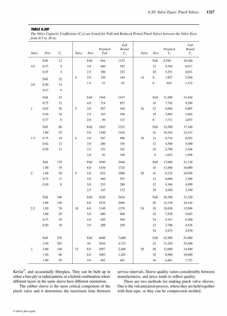
TABLE 6.20fThe Valve Capacity Coefficients (Cvs) are Listed for Full and Reduced Ported Pinch Valves between the Valve Sizesfrom 0.5 to 30 in.
Valve Port Cv Valve PortPrepinch
Full
FullRound
Cv Valve PortPrepinch
Cv
FullRound
Cv
1/2
Full 12 Full 944 1133 Full 8,550 10,260
0.37 9 3.0 460 552 12 5,764 6,917
0.25 4 2.5 186 223 10 3,351 4,021
Full 32 4 2.0 120 144 14 8 1,837 2,204
3/4 0.50 14 1.5 51 61 6 943 1,132
0.37 8
Full 42 Full 1364 1637 Full 11,200 13,440
0.75 31 4.0 714 857 14 7,745 9,294
1 0.62 28 5 3.0 287 344 16 12 5,004 6,005
0.50 18 2.5 163 196 10 3,002 3,602
0.37 6 2.0 94 113 8 1,711 2,053
Full 86 Full 1843 2212 Full 14,300 17,160
1.00 35 5.0 1180 1416 16 10,344 12,413
1.5 0.75 18 6 4.0 567 680 18 14 6,710 8,052
0.62 12 3.0 280 336 12 4,500 5,400
0.50 11 2.5 152 182 10 2,790 3,348
2.0 91 109 8 1,632 1,958
Full 170 Full 3040 3648 Full 17,600 21,120
1.50 79 6.0 1436 1723 18 13,400 16,080
2 1.00 30 8 5.0 832 1000 20 16 9,125 10,950
0.75 17 4.0 460 553 14 6,000 7,200
0.50 8 3.0 233 280 12 4,166 4,999
2.5 143 172 10 2,650 3,180
Full 346 Full 4520 5424 Full 26,100 31,320
2.00 156 8.0 2534 3040 20 15,120 18,144
2.5 1.50 70 10 6.0 1149 1379 24 18 10,830 12,996
1.00 29 5.0 800 960 16 7,536 9,043
0.75 18 4.0 420 504 14 5,167 6,200
0.50 10 3.0 208 250 12 3,780 4,536
10 2,475 2,970
Full 576 Full 6400 7,680 Full 42,500 51,000
2.50 293 10 3936 4,723 24 21,250 25,500
3 2.00 148 12 8.0 2057 2,468 30 20 12,000 14,400
1.50 66 6.0 1003 1,203 18 8,900 10,680
1.00 29 4.0 402 482 16 6,461 7,753
© 2006 by Béla Lipták
1328 Control Valve Selection and Sizing
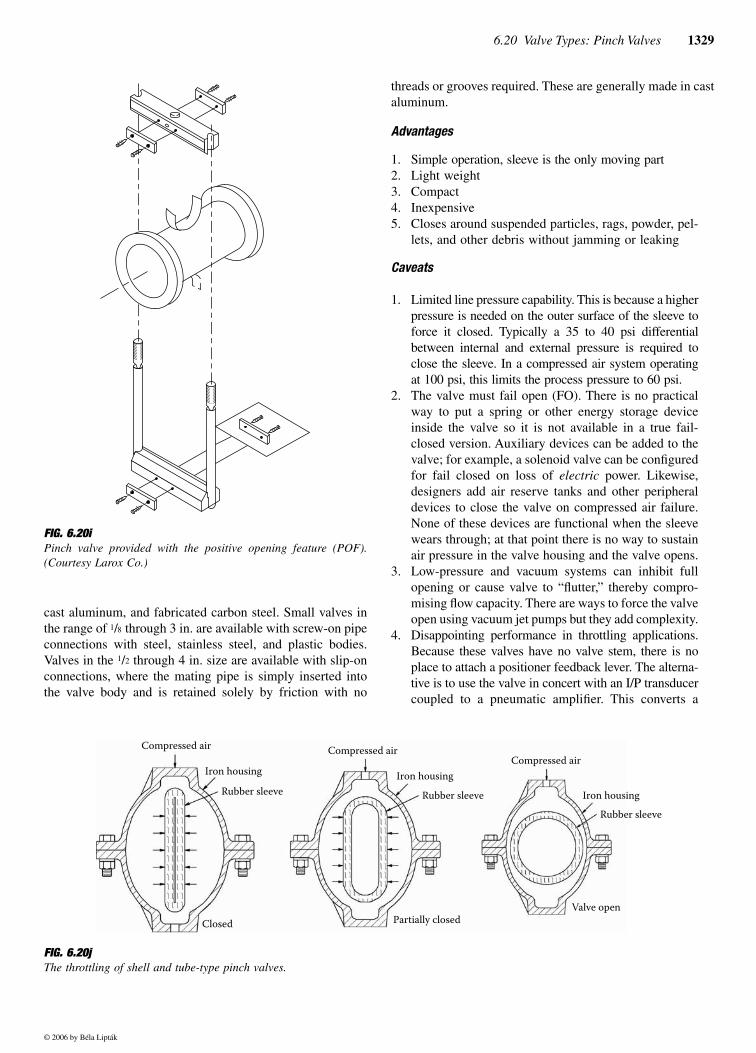
An important feature of the sleeve design is the positiveopening feature (POF), which is illustrated in Figure 6.20i.This feature is provided by a pair of rubber and fabric tabs,which are molded into the trunk of the pinch valve sleeve.These tabs are clamped to the pinch bars. They force thesleeve to open properly when there is no process pressure onthe inside to open it, which is of value if the sleeve has beenclosed for an extended period of time.
PINCH VALVE TYPES
Pressure Limitations
As was shown in Figure 6.20a, shell and tube-type pinch valveshave the lowest pressure rating. Their main limitation is theavailable pressure of the compressed air used to close the valve.
Standard mechanically pinched valves can operate againstline pressure in the range of 75 to 200 PSIG, depending on size.The limitation is the strength of the fabric reinforcement in therubber sleeve. Special-order pinch valves can be fabricated forhigh-pressure service. Manufacturers use exotic fabrics includ-ing Kevlar and the latest engineering software to create hybridsleeves built up with a mix of bias ply and radial layers toincrease working pressure.
Shell and Tube Design
The simplest pinch valve is the shell and tube type, which isalso referred to as a direct operated or as a jacketed pinchvalve. This design consists of a cast iron, aluminum, or plasticshell with a rubber sleeve inside. For a cost comparisonbetween shell and tube-type and handwheel-operated pinchvalves, refer to Figure 6.20c.
As shown in Figure 6.20j, injecting compressed air into thehousing causes the rubber sleeve to collapse, thereby blockingflow of the process fluid through the valve. The valve housingis usually configured to coax the sleeve into a straight-lineclosure to operate with the lowest possible differential pressure.
Flanged bodies are available in 1 through 72 in. sizes.Body material for flanged valves is cast iron, ductile iron,
FIG. 6.20gPinch valves design variations and feature options.
Pinchvalves
Shell & Tube
Mechanicallypinched
Openframe
Enclosed
Hydraulic
Pneumatic
Pneumatic
Electric
Hand wheel
Pneumatic
Electric
Hand wheel
Failopen
Failopen
Failopen
Failopen
Failclosed
Failclosed
TABLE 6.20hComparative Properties of Elastomers Used to Make Pinch Valve Sleeves
ANSI/ASTM D1418-77 NR/IR CR NBR CHR CSM EPDM FKM AFMU SI
Trade Names
Poly Isoprene
Pure Gum NeopreneNitrileBuna-N Chloro Butyl Hypalon Nordel
VitonFluorel Teflon Silicone
Durometer-A (typical)
37–45 50 55 55 70 60 73 52D 40–80
Abrasion Resistance
Outstanding Excellent Good Good Good Very good Fair Poor Poor
Tensile Strength,psi
3000 1800 1700 — 1800 1800 1470 2500 1500
Elongation% 640 550 460 — — 350 300 250 -
T range °F −30 � +180 −20 � +220 −20 � +230 −40 � +250 −10 � +275 −50 � +325 −15 � +375 −120 � +450 −60 � +460
Acid Resistance
Diluted
Fair to good Excellent Good Excellent Excellent Excellent Excellent Best Excellent
Acid Resistance
Concentrated
Fair to good Good Good Good Very good Excellent Excellent Best Fair
Oil Tolerance Poor Good Excellent Poor Good Poor to good Excellent Excellent Fair
© 2006 by Béla Lipták
6.20 Valve Types: Pinch Valves 1329
cast aluminum, and fabricated carbon steel. Small valves inthe range of 1/8 through 3 in. are available with screw-on pipeconnections with steel, stainless steel, and plastic bodies.Valves in the 1/2 through 4 in. size are available with slip-onconnections, where the mating pipe is simply inserted intothe valve body and is retained solely by friction with no
threads or grooves required. These are generally made in castaluminum.
Advantages
1. Simple operation, sleeve is the only moving part2. Light weight3. Compact4. Inexpensive5. Closes around suspended particles, rags, powder, pel-
lets, and other debris without jamming or leaking
Caveats
1. Limited line pressure capability. This is because a higherpressure is needed on the outer surface of the sleeve toforce it closed. Typically a 35 to 40 psi differentialbetween internal and external pressure is required toclose the sleeve. In a compressed air system operatingat 100 psi, this limits the process pressure to 60 psi.
2. The valve must fail open (FO). There is no practicalway to put a spring or other energy storage deviceinside the valve so it is not available in a true fail-closed version. Auxiliary devices can be added to thevalve; for example, a solenoid valve can be configuredfor fail closed on loss of electric power. Likewise,designers add air reserve tanks and other peripheraldevices to close the valve on compressed air failure.None of these devices are functional when the sleevewears through; at that point there is no way to sustainair pressure in the valve housing and the valve opens.
3. Low-pressure and vacuum systems can inhibit fullopening or cause valve to “flutter,” thereby compro-mising flow capacity. There are ways to force the valveopen using vacuum jet pumps but they add complexity.
4. Disappointing performance in throttling applications.Because these valves have no valve stem, there is noplace to attach a positioner feedback lever. The alterna-tive is to use the valve in concert with an I/P transducercoupled to a pneumatic amplifier. This converts a
FIG. 6.20i Pinch valve provided with the positive opening feature (POF).(Courtesy Larox Co.)
FIG. 6.20j The throttling of shell and tube-type pinch valves.
Compressed air
Iron housing
Rubber sleeveIron housing
Iron housingRubber sleeve
Rubber sleeve
Closed
Compressed airCompressed air
Partially closedValve open
© 2006 by Béla Lipták
1330 Control Valve Selection and Sizing
4–20 mADC electronic signal to a pneumatic 0–100PSIG signal that is introduced into the valve shell. Thisvaries the opening of the rubber sleeve, but withoutany feedback in the valve. The only means of closingthe loop is through the measuring element and con-troller. This makes for sluggish response, erratic sta-bility, and shallow turndown. Modulating shell andtube valves are generally limited to slow, linear appli-cations like level control on large vessels. Exceptionto the rule: For pH control, use a shell and tube pinchvalve with a solenoid valve instead of an I/P trans-ducer. Configure the controller for pulse width mod-ulation (PWM) with a s-l-o-w time base around 10sec. This introduces a response time lag but cranks theturndown up to 100:1 or better with zero sleeve abra-sion. Want well all-around modulating control? Readon and see how well mechanically pinched valveswork in throttling applications.
5. Limited sleeve life. In mechanically operated pinchvalves, designers add extra fabric for ample reservestrength. Designing a shell and tube valve does notoffer this luxury. Additional fabric adds stiffness andincreases the differential pressure needed to close thevalve. This drives the sleeve design to the minimumnumber of fabric layers. The result is that the fabricoperates right up to its yield point. After a certainnumber of open-close cycles the fabric fails throughfatigue and the sleeve delaminates. Sleeve life in ashell and tube pinch valve operating at its maximumrated pressure is usually around a mean of 75,000cycles with a variation of ±25,000.
In comparison, mechanical pinch valves operate throughpractically an unlimited number of cycles because the fabricis operating at reduced stress. Mechanical pinch valves oper-ating for millions of cycles over a period of 20 years are notuncommon.
One method to increase the sleeve life is to regulate thecompressed air pressure to precisely 40 psi over process
pressure. For example, a 4 in. valve might be rated for 65 psimax process pressure with 105 psi max compressed air pres-sure. However, if the actual process pressure is 25 PSIG,reducing the air pressure from 105 down to 65 PSIG greatlyreduces stress in the reinforcing fabric. This increases sleevelife by about 50%. The additional cost of an air pressureregulator pays for itself in improved sleeve life.
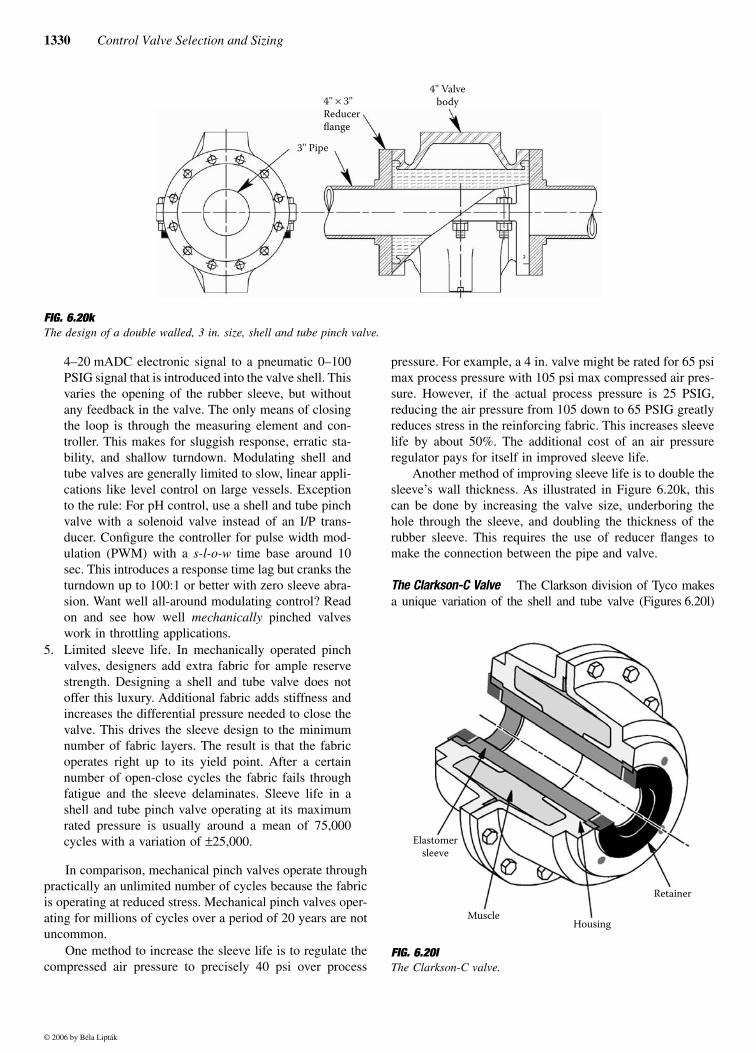
Another method of improving sleeve life is to double thesleeve’s wall thickness. As illustrated in Figure 6.20k, thiscan be done by increasing the valve size, underboring thehole through the sleeve, and doubling the thickness of therubber sleeve. This requires the use of reducer flanges tomake the connection between the pipe and valve.
The Clarkson-C Valve The Clarkson division of Tyco makesa unique variation of the shell and tube valve (Figures 6.20l)
FIG. 6.20k The design of a double walled, 3 in. size, shell and tube pinch valve.
3'' Pipe
4'' × 3''Reducerflange
4'' Valvebody
FIG. 6.20l The Clarkson-C valve.
Elastomersleeve
MuscleHousing
Retainer
© 2006 by Béla Lipták
6.20 Valve Types: Pinch Valves 1331
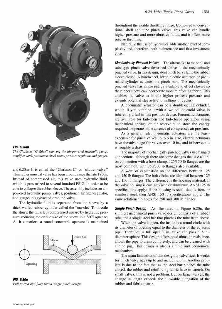
and 6.20m. It is called the “Clarkson-C” or “shutter valve.”This rather unusual valve has been around since the late 1960s.Instead of compressed air, this valve uses hydraulic fluid,which is pressurized to several hundred PSIG, in order to beable to collapse the rubber sleeve. The assembly includes an air-powered hydraulic pump, valves, positioner, air filter-regulator,and gauges piggybacked onto the valve.
The hydraulic fluid is separated from the sleeve by athick-walled rubber cylinder called the “muscle.” To throttlethe slurry, the muscle is compressed inward by hydraulic pres-sure, reducing the orifice size of the sleeve in a 360° squeeze.As it constricts, a round concentric aperture is maintained
throughout the usable throttling range. Compared to conven-tional shell and tube pinch valves, this valve can handlehigher pressure and more abrasive fluids, and it offers moreprecise throttling.
Naturally, the use of hydraulics adds another level of com-plexity and, therefore, both maintenance and first-investmentcosts.
Mechanically Pinched Valves The alternative to the shell andtube-type pinch valve described above is the mechanicallypinched valve. In this design, steel pinch bars clamp the rubbersleeve closed. A handwheel, lever, electric actuator, or pneu-matic cylinder actuates the pinch bars. The mechanicallypinched valve has ample energy available to effect closure sothe rubber sleeve can incorporate more reinforcing fabric. Thisenables the valve to handle higher process pressure andextends potential sleeve life to millions of cycles.
A pneumatic actuator can be a double-acting cylinder,which, if you combine it with a two-coil solenoid valve, isinherently a fail-in-last position device. Pneumatic actuatorsare available for fail-open and fail-closed operation, usingmechanical springs or air reservoirs to store the energyrequired to operate in the absence of compressed air pressure.
As a general rule, pneumatic actuators are the least-expensive for pinch valves up to 6 in. size, electric actuatorshave the advantage for valves over 10 in., and in between itis roughly a draw.
The majority of mechanically pinched valves use flangedconnections, although there are some designs that use a slip-on connection with a hose clamp. 125/150 lb flanges are themost common, with 250/300 lb flanges also available.
A word of explanation on the difference between 125and 150 lb flanges: The bolt circles are identical between 125and 150 lb flanges. The difference is the housing material: Ifthe valve housing is cast grey iron or aluminum, ANSI 125 lbspecifications apply; if the housing is steel, ductile iron, orstainless steel, then ANSI 150 lb specifications apply. Thesame relationship holds for 250 and 300 lb flanges.
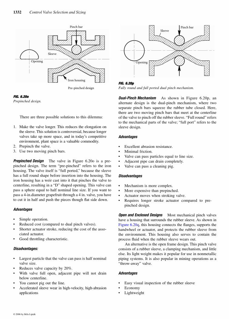
Single Pinch Design As illustrated in Figure 6.20n, thesimplest mechanical pinch valve design consists of a rubbertube and a single steel bar that pinches the tube from above.
When the valve is open, the inside is a round circle withits diameter of opening equal to the diameter of the adjacentpipe. Therefore, a full open 2 in. valve can pass a 2-in.-diameter sphere. This design offers good abrasion resistance,allows the pipe to drain completely, and can be cleaned witha pipe pig. This design is also a simple and economicalmechanism.
The main limitation of this design is valve size: It worksfor pinch valve sizes up to and including 3 in. Another prob-lem is due to the fact that as the steel bar pinches the tubeclosed, the rubber and reinforcing fabric have to stretch. Onsmall valves, this is not a problem. But on larger valves, thechange in length exceeds the allowable elongation of therubber and fabric matrix.
FIG. 6.20m The Clarkson “C-Valve” showing the air-powered hydraulic pump,amplifier, tank, positioner, check valve, pressure regulator, and gauges.
FIG. 6.20n Full ported and fully round single pinch design.
Sleeve
Opening
Pinch bar
© 2006 by Béla Lipták
1332 Control Valve Selection and Sizing
There are three possible solutions to this dilemma:
1. Make the valve longer. This reduces the elongation onthe sleeve. This solution is controversial, because longervalves take up more space, and in today’s competitiveenvironment, plant space is a valuable commodity.
2. Prepinch the valve. 3. Use two moving pinch bars.
Prepinched Design The valve in Figure 6.20o is a pre-pinched design. The term “pre-pinched” refers to the ironhousing. The valve itself is “full ported,” because the sleevehas a full round shape before insertion into the housing. Theiron housing has a weir cast into it that pinches the valve tocenterline, resulting in a “D” shaped opening. This valve canpass a sphere equal to half nominal line size. If you want topass a 4-in.diameter grapefruit through a 4 in. valve, you haveto cut it in half and push the pieces though flat side down.
Advantages
• Simple operation. • Reduced cost (compared to dual pinch valves). • Shorter actuator stroke, reducing the cost of the asso-
ciated actuator.• Good throttling characteristic.
Disadvantages:
• Largest particle that the valve can pass is half nominalvalve size.
• Reduces valve capacity by 20%. • With valve full open, adjacent pipe will not drain
below centerline. • You cannot pig out the line.• Accelerated sleeve wear in high-velocity, high-abrasion
applications
Dual-Pinch Mechanism As shown in Figure 6.20p, analternate design is the dual-pinch mechanism, where twoseparate pinch bars squeeze the rubber tube closed. Here,there are two moving pinch bars that meet at the centerlineof the valve to pinch off the rubber sleeve. “Full round” refersto the mechanical parts of the valve; “full port” refers to thesleeve design.
Advantages
• Excellent abrasion resistance.• Minimal friction.• Valve can pass particles equal to line size.• Adjacent pipe can drain completely.• Valve can pass a cleaning pig.
Disadvantages
• Mechanism is more complex. • More expensive than prepinched. • Actuator moves when stroking valve.• Requires longer stroke actuator compared to pre-
pinched design.
Open and Enclosed Designs Most mechanical pinch valveshave a housing that surrounds the rubber sleeve. As shown inFigure 6.20q, this housing connects the flanges, supports thehandwheel or actuator, and protects the rubber sleeve fromthe environment. This housing also serves to contain theprocess fluid when the rubber sleeve wears out.
An alternative is the open frame design. This pinch valveconsists of a rubber sleeve, a clamping mechanism, and littleelse. Its light weight makes it popular for use in nonmetallicpiping systems. It is also popular in mining operations as a“throw-away” valve.
Advantages
• Easy visual inspection of the rubber sleeve• Economy• Lightweight
FIG. 6.20o Prepinched design.
Pinch bar
Opening
Sleeve
Iron housing
Pre-pinched designFIG. 6.20p Fully round and full ported dual pinch mechanism.
Sleeve
Opening
Pinch bar
© 2006 by Béla Lipták
6.20 Valve Types: Pinch Valves 1333
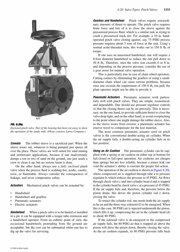
Caveats The rubber sleeve is a sacrificial part. When thesleeve wears out, whatever is being pumped just sprays allover the place. These valves are well suited for sand miningand stormwater applications, because if one inadvertentlydumps a ton or two of sand on the ground, one just sends acrew to clean it up, but no serious harm is done.
On the other hand, always use a fully enclosed pinchvalve when the process fluid is scalding hot, acidic, caustic,toxic, or flammable. Always consider the consequences ofleakage, and never compromise safety.
Actuators Mechanical pinch valves can be actuated by:
• Handwheel• Handwheel and gearbox • Pneumatic actuators• Electric actuators
Handwheel When a pinch valve is to be buried or installedin a pit, it can be equipped with a torque tube extension anda handwheel operator. From an esthetic point of view, theoccasional handwheels protruding from the ground areacceptable, but the cost can be substantial when one has todig up the valve for servicing.
Gearbox and Handwheel Pinch valves require extraordi-nary amounts of thrust to operate. The pinch valve requiresbrute force and lots of it to close the sleeve against thepressurized process fluid, which is a similar task as trying tocrush a pressurized truck tire. For example, a 10 in. hand-operated pinch valve closing against, say, 75 PSIG processpressure requires about 5 tons of force at the seat. Using anormal acme-threaded stem, this works out to 150 ft lbf oftorque.
If one uses an unassisted handwheel, one will require a6-foot diameter handwheel to reduce the rim pull down to50 ft lbf. Therefore, once the valve size exceeds 6 or 8 in.and depending on the process pressure, consider the use ofa gear assist for manual valve operation.
This is particularly true in case of chain wheel operators.Cutting corners by eliminating the gearbox or using a small-diameter chain wheel can cause serious problems, becauseonce one exceeds the requirement of 150 ft lbf rim pull, theplant operator might not be able to provide it.
Pneumatic Actuators Pneumatic actuators work particu-larly well with pinch valves. They are simple, economical,and dependable. One should use pressure regulator controlsso that the closing thrust can be set precisely. This is neces-sary, on the one hand, to provide sufficient thrust to close thevalve drop tight, and on the other hand, to avoid overpinchingto the point where one might damage the rubber sleeve. Also,as the sleeve wears from erosion, a pneumatic actuator hasreserve travel to compensate for the lost material.
The most common pneumatic actuator used on pinchvalves is the conventional double-acting air cylinder. Whenthe air supply fails, a double-acting air cylinder fails in itslast position.
Using an Air Cushion The pneumatic cylinder can be sup-plied with a spring or air cushion on either top or bottom forfail-closed or fail-open operation. Air cushions are cheaperthan springs but are less reliable, because a minor leak canvoid the actuator’s ability to execute the proper fail action.
The operation of the air cushion is shown in Figure 6.20r,where compressed air is supplied through tube a to pressureregulator b, which reduces the pressure to 45 PSIG. Air flowsthrough check valve c and into cylinder head d and is trappedin the cylinder head by check valve c at a pressure of 45 PSIG.If the air supply fails and, therefore, the pressure below thepiston drops, this drives the piston cylinder rod e down,closing the valve.
To retract the cylinder rod, one needs both the air supplyto be on and the three-way solenoid (f) to be energized. Whenthis is the case, 90 PSIG air is injected underneath the piston,which lifts it up, compressing the air in the cylinder head (d)to about 80 PSIG.
If the solenoid valve is de-energized or the compressedair supply fails, the 80 PSIG air that is trapped air above thepiston will drive the piston down, thereby closing the valve.As the air cushion expands, its 80 PSIG pressure falls back
FIG. 6.20q Enclosed pinch valve. Part of the housing has been cut away to showthe operation of the guide rods. (Photo courtesy Larox Company.)
© 2006 by Béla Lipták
1334 Control Valve Selection and Sizing
to 45 PSIG. Therefore, the cylinder has to be sized to operateat this reduced pressure.
Suspension Bag One pinch valve manufacturer hasdevised a particularly clever pneumatic actuator, where insteadof a conventional air cylinder, a rubber pneumatic suspensionbag is used as the actuator (Figure 6.20s). One advantage ofthis actuator on modulating applications is that it has a nonlinear
thrust output. The reason for this is that as the suspension bagexpands vertically, it “necks in” around its circumference. Thiseliminates breakaway friction and overtravel, enabling themto position a valve with 1/1,000th in. precision.
Pneumatic suspension bags are normally used in trucksand buses as shock absorbers. They are visible on tractor-trailers between the frame and axel assembly. Air bags havea decades-long track record of reliable operation in temper-ature extremes, rain, snow, sleet, dust, oil, vibration, andshock. They tolerate contamination of the compressed airsystem without adverse effects. They require no lubricationand operate virtually friction free.
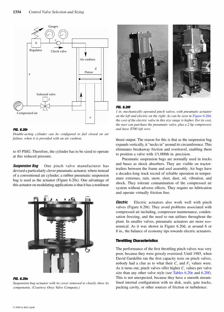
Electric Electric actuators also work well with pinchvalves (Figure 6.20t). They avoid problems associated withcompressed air including, compressor maintenance, conden-sation freezing, and the need to run airlines throughout theplant. In smaller valves, pneumatic actuators are more eco-nomical. As it was shown in Figure 6.20d, at around 6 or8 in., the balance of economy tips towards electric actuators.
Throttling Characteristics
The performance of the first throttling pinch valves was verypoor, because they were grossly oversized. Until 1985, whenDavid Gardellin ran the first capacity tests on pinch valves,nobody had a clue as to what their Cv and FL values were.As it turns out, pinch valves offer higher Cv values per valvesize than any other valve style (see Tables 6.20e and 6.20f).This is not unexpected, because they have a smooth stream-lined internal configuration with no disk, seals, gate tracks,packing cavity, or other sources of friction or turbulence.
FIG. 6.20r Double-acting cylinder can be configured to fail closed on airfailure, when it is provided with an air cushion.
FIG. 6.20sSuspension bag actuator with its cover removed to clearly show itscomponents. (Courtesy Onyx Valve Company.)
FIG. 6.20t 1 in. mechanically operated pinch valves, with pneumatic actuatoron the left and electric on the right. As can be seen in Figure 6.20d,the cost of the electric valve in this size range is higher. For its cost,the user can purchase the pneumatic valve, plus a 2 hp compressor,and have $700 left over.
© 2006 by Béla Lipták
Gauges
Regulator Check valve
a
bc
Solenoid valve
Compressed air
Air cushion
Pistond
e
f
6.20 Valve Types: Pinch Valves 1335
The reason for the poor performance of the full-portedmodulating pinch valves is their excess capacity. The conse-quence of it being oversized is that the automatic controllertends to operate it nearly fully closed, down near the seat.This precipitates two problems:
One is accelerated sleeve erosion caused by the highvelocity flow. Pumping abrasive slurry through a pinch valverunning just off the seat is like firing a shotgun through amail slot. The sleeve doesn’t last very long.
The other problem is poor control quality. This wasbecause if a 6 in. valve is used, but it needs to open only 1/4in. to pass the required maximum flow, throttling over suchnarrow range is next to impossible, and no positioner cancorrect that.
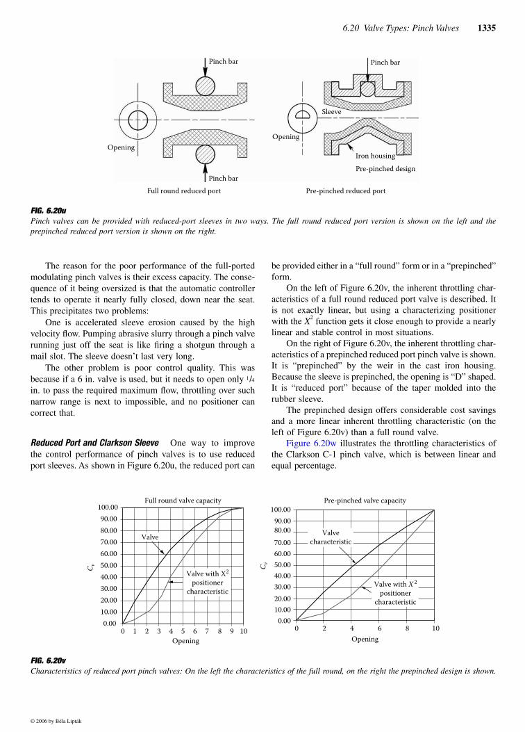
Reduced Port and Clarkson Sleeve One way to improvethe control performance of pinch valves is to use reducedport sleeves. As shown in Figure 6.20u, the reduced port can
be provided either in a “full round” form or in a “prepinched”form.
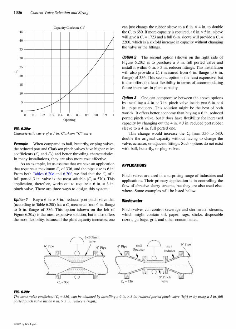
On the left of Figure 6.20v, the inherent throttling char-acteristics of a full round reduced port valve is described. Itis not exactly linear, but using a characterizing positionerwith the X2 function gets it close enough to provide a nearlylinear and stable control in most situations.
On the right of Figure 6.20v, the inherent throttling char-acteristics of a prepinched reduced port pinch valve is shown.It is “prepinched” by the weir in the cast iron housing.Because the sleeve is prepinched, the opening is “D” shaped.It is “reduced port” because of the taper molded into therubber sleeve.
The prepinched design offers considerable cost savingsand a more linear inherent throttling characteristic (on theleft of Figure 6.20v) than a full round valve.
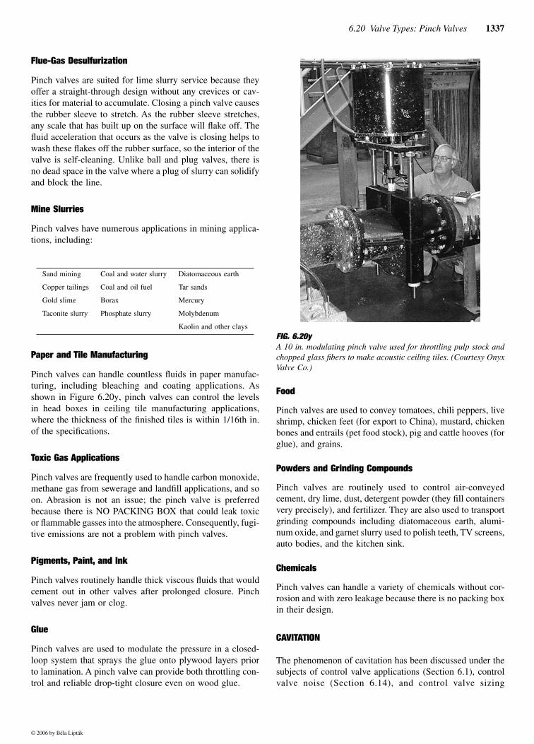
Figure 6.20w illustrates the throttling characteristics ofthe Clarkson C-1 pinch valve, which is between linear andequal percentage.
FIG. 6.20u Pinch valves can be provided with reduced-port sleeves in two ways. The full round reduced port version is shown on the left and theprepinched reduced port version is shown on the right.
OpeningOpening
Pinch bar Pinch bar
Pinch bar
Sleeve
Iron housingPre-pinched design
Full round reduced port Pre-pinched reduced port
FIG. 6.20v Characteristics of reduced port pinch valves: On the left the characteristics of the full round, on the right the prepinched design is shown.
Full round valve capacity
0.0010.0020.0030.0040.0050.0060.0070.0080.0090.00
100.00
0 1 2 3 4 5 6 7 8 9 10Opening
C v
Valve
Valve with X2
positionercharacteristic
Pre-pinched valve capacity
Opening
0.0010.0020.0030.0040.0050.0060.0070.0080.0090.00
100.00
C v
Valvecharacteristic
Valve with X 2
positionercharacteristic
0 2 4 6 8 10
© 2006 by Béla Lipták
1336 Control Valve Selection and Sizing
Example When compared to ball, butterfly, or plug valves,the reduced port and Clarkson pinch valves have higher valvecoefficients (Cv and FL) and better throttling characteristics.In many installations, they are also more cost effective.
As an example, let us assume that we have an applicationthat requires a maximum Cv of 336, and the pipe size is 6 in.From both Tables 6.20e and 6.20f, we find that the Cv of afull ported 3 in. valve is the most suitable (Cv = 570). Thisapplication, therefore, works out to require a 6 in. × 3 in.pinch valve. There are three ways to design this system:
Option 1 Buy a 6 in. × 3 in. reduced port pinch valve that(according to Table 6.20f) has a Cv measured from 6 in. flangeto 6 in. flange of 336. This option (shown on the left ofFigure 6.20x) is the most expensive solution, but it also offersthe most flexibility, because if the plant capacity increases, one
can just change the rubber sleeve to a 6 in. × 4 in. to doublethe Cv to 680. If more capacity is required, a 6 in. × 5 in. sleevewill give a Cv = 1723 and a full 6-in. sleeve will provide a Cv =2200, which is a sixfold increase in capacity without changingthe valve or the fittings.
Option 2 The second option (shown on the right side ofFigure 6.20x) is to purchase a 3 in. full ported valve andinstall it within 6 in. × 3 in. reducer fittings. This installationwill also provide a Cv (measured from 6 in. flange to 6 in.flange) of 336. This second option is the least expensive, butit also offers the least flexibility in terms of accommodatingfuture increases in plant capacity.
Option 3 One can compromise between the above optionsby installing a 4 in. × 3 in. pinch valve inside two 6 in. × 4in. pipe reducers. This solution might be the best of bothworlds. It offers better economy than buying a 6 in. reducedported pinch valve, but it does have flexibility for increasedcapacity by changing out the 4 in. × 3 in. reduced port rubbersleeve to a 4 in. full ported one.
This change would increase the Cv from 336 to 680:double the original capacity without having to change thevalve, actuator, or adjacent fittings. Such options do not existwith ball, butterfly, or plug valves.
APPLICATIONS
Pinch valves are used in a surprising range of industries andapplications. Their primary application is in controlling theflow of abrasive slurry streams, but they are also used else-where. Some examples will be listed below.
Wastewater
Pinch valves can control sewerage and stormwater streams,which might contain oil, paper, rags, sticks, disposablerazors, garbage, grit, and other contaminates.
FIG. 6.20wCharacteristic curve of a 1 in. Clarkson “C” valve.
0
5
10
15
20
25
30
35
40
45
0 0.1 0.2 0.3 0.4 0.5 0.6 0.7 0.8 0.9 1Opening
C v
Capacity Clarkson-C1''
FIG. 6.20x The same valve coefficient (Cv = 336) can be obtained by installing a 6 in. × 3 in. reduced ported pinch valve (left) or by using a 3 in. fullported pinch valve inside 6 in. × 3 in. reducers (right).
6'' Pipe
6×3 Pinchvalve
6'' Pipe
Cv = 336 Cv = 336
6'' Pipe 6×3Reducer
6×3Reducer
6'' Pipe
3'' Pinchvalve
© 2006 by Béla Lipták
6.20 Valve Types: Pinch Valves 1337
Flue-Gas Desulfurization
Pinch valves are suited for lime slurry service because theyoffer a straight-through design without any crevices or cav-ities for material to accumulate. Closing a pinch valve causesthe rubber sleeve to stretch. As the rubber sleeve stretches,any scale that has built up on the surface will flake off. Thefluid acceleration that occurs as the valve is closing helps towash these flakes off the rubber surface, so the interior of thevalve is self-cleaning. Unlike ball and plug valves, there isno dead space in the valve where a plug of slurry can solidifyand block the line.
Mine Slurries
Pinch valves have numerous applications in mining applica-tions, including:
Paper and Tile Manufacturing
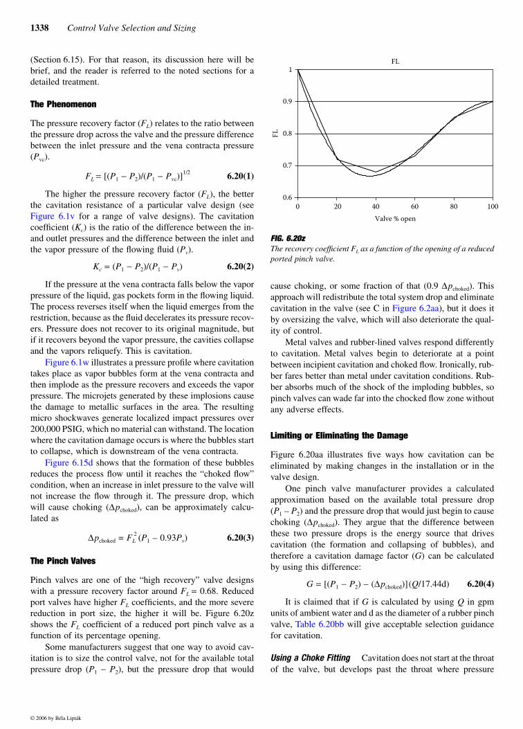
Pinch valves can handle countless fluids in paper manufac-turing, including bleaching and coating applications. Asshown in Figure 6.20y, pinch valves can control the levelsin head boxes in ceiling tile manufacturing applications,where the thickness of the finished tiles is within 1/16th in.of the specifications.
Toxic Gas Applications
Pinch valves are frequently used to handle carbon monoxide,methane gas from sewerage and landfill applications, and soon. Abrasion is not an issue; the pinch valve is preferredbecause there is NO PACKING BOX that could leak toxicor flammable gasses into the atmosphere. Consequently, fugi-tive emissions are not a problem with pinch valves.
Pigments, Paint, and Ink
Pinch valves routinely handle thick viscous fluids that wouldcement out in other valves after prolonged closure. Pinchvalves never jam or clog.
Glue
Pinch valves are used to modulate the pressure in a closed-loop system that sprays the glue onto plywood layers priorto lamination. A pinch valve can provide both throttling con-trol and reliable drop-tight closure even on wood glue.
Food
Pinch valves are used to convey tomatoes, chili peppers, liveshrimp, chicken feet (for export to China), mustard, chickenbones and entrails (pet food stock), pig and cattle hooves (forglue), and grains.
Powders and Grinding Compounds
Pinch valves are routinely used to control air-conveyedcement, dry lime, dust, detergent powder (they fill containersvery precisely), and fertilizer. They are also used to transportgrinding compounds including diatomaceous earth, alumi-num oxide, and garnet slurry used to polish teeth, TV screens,auto bodies, and the kitchen sink.
Chemicals
Pinch valves can handle a variety of chemicals without cor-rosion and with zero leakage because there is no packing boxin their design.
CAVITATION
The phenomenon of cavitation has been discussed under thesubjects of control valve applications (Section 6.1), controlvalve noise (Section 6.14), and control valve sizing
Sand mining
Copper tailings
Gold slime
Taconite slurry
Coal and water slurry
Coal and oil fuel
Borax
Phosphate slurry
Diatomaceous earth
Tar sands
Mercury
Molybdenum
Kaolin and other claysFIG. 6.20yA 10 in. modulating pinch valve used for throttling pulp stock andchopped glass fibers to make acoustic ceiling tiles. (Courtesy OnyxValve Co.)
© 2006 by Béla Lipták
1338 Control Valve Selection and Sizing
(Section 6.15). For that reason, its discussion here will bebrief, and the reader is referred to the noted sections for adetailed treatment.
The Phenomenon
The pressure recovery factor (FL) relates to the ratio betweenthe pressure drop across the valve and the pressure differencebetween the inlet pressure and the vena contracta pressure(Pvc).
FL = [(P1 − P2)/(P1 − Pvc)]1/2 6.20(1)
The higher the pressure recovery factor (FL), the betterthe cavitation resistance of a particular valve design (seeFigure 6.1v for a range of valve designs). The cavitationcoefficient (Kc) is the ratio of the difference between the in-and outlet pressures and the difference between the inlet andthe vapor pressure of the flowing fluid (Pv).
Kc = (P1 − P2)/(P1 − Pv) 6.20(2)
If the pressure at the vena contracta falls below the vaporpressure of the liquid, gas pockets form in the flowing liquid.The process reverses itself when the liquid emerges from therestriction, because as the fluid decelerates its pressure recov-ers. Pressure does not recover to its original magnitude, butif it recovers beyond the vapor pressure, the cavities collapseand the vapors reliquefy. This is cavitation.
Figure 6.1w illustrates a pressure profile where cavitationtakes place as vapor bubbles form at the vena contracta andthen implode as the pressure recovers and exceeds the vaporpressure. The microjets generated by these implosions causethe damage to metallic surfaces in the area. The resultingmicro shockwaves generate localized impact pressures over200,000 PSIG, which no material can withstand. The locationwhere the cavitation damage occurs is where the bubbles startto collapse, which is downstream of the vena contracta.
Figure 6.15d shows that the formation of these bubblesreduces the process flow until it reaches the “choked flow”condition, when an increase in inlet pressure to the valve willnot increase the flow through it. The pressure drop, whichwill cause choking (∆pchoked), can be approximately calcu-lated as
∆pchoked = FL2 (P1 – 0.93Pv) 6.20(3)
The Pinch Valves
Pinch valves are one of the “high recovery” valve designswith a pressure recovery factor around FL = 0.68. Reducedport valves have higher FL coefficients, and the more severereduction in port size, the higher it will be. Figure 6.20zshows the FL coefficient of a reduced port pinch valve as afunction of its percentage opening.
Some manufacturers suggest that one way to avoid cav-itation is to size the control valve, not for the available totalpressure drop (P1 – P2), but the pressure drop that would
cause choking, or some fraction of that (0.9 ∆pchoked). Thisapproach will redistribute the total system drop and eliminatecavitation in the valve (see C in Figure 6.2aa), but it does itby oversizing the valve, which will also deteriorate the qual-ity of control.
Metal valves and rubber-lined valves respond differentlyto cavitation. Metal valves begin to deteriorate at a pointbetween incipient cavitation and choked flow. Ironically, rub-ber fares better than metal under cavitation conditions. Rub-ber absorbs much of the shock of the imploding bubbles, sopinch valves can wade far into the chocked flow zone withoutany adverse effects.
Limiting or Eliminating the Damage
Figure 6.20aa illustrates five ways how cavitation can beeliminated by making changes in the installation or in thevalve design.
One pinch valve manufacturer provides a calculatedapproximation based on the available total pressure drop(P1 – P2) and the pressure drop that would just begin to causechoking (∆pchoked). They argue that the difference betweenthese two pressure drops is the energy source that drivescavitation (the formation and collapsing of bubbles), andtherefore a cavitation damage factor (G) can be calculatedby using this difference:
G = [(P1 − P2) – (∆pchoked)](Q/17.44d) 6.20(4)
It is claimed that if G is calculated by using Q in gpmunits of ambient water and d as the diameter of a rubber pinchvalve, Table 6.20bb will give acceptable selection guidancefor cavitation.
Using a Choke Fitting Cavitation does not start at the throatof the valve, but develops past the throat where pressure
FIG. 6.20z The recovery coefficient FL as a function of the opening of a reducedported pinch valve.
FL
0.6
0.7
0.8
0.9
1
0 20 40 60 80 100Valve % open
LF
© 2006 by Béla Lipták

6.20 Valve Types: Pinch Valves 1339
begins to recover. As a result, cavitation damage occursdownstream of the valve throat and destroys the pinch valve’ssleeve between the pinch point and the valve exit. Modulatingpinch valves are usually supplied with a reduced port sleeve.The sleeve is molded with a venturi shape that tapers downto a small diameter in the center of the valve. The sleeve isnormally symmetrical, tapered on both inlet and outlet so thevalve can be installed for either flow direction. This designis vulnerable to cavitation damage.
Revising the sleeve design to an asymmetrical shape willenable the valve to withstand high levels of cavitation(Figure 6.20cc). This design is called a “trumpet mouth” or“cone sleeve.” The thicker rubber at the valve outlet can
absorb more cavitation damage. There are several ways toexploit this feature to tolerate even higher levels of cavitationwith minimum sleeve damage.
One method is to install the valve at the end of the pipingrun, allowing the pressure to recover as the fluid emergesfrom the piping system. Here the cavities form after theyhave emerged from the choke fitting, where they cascadeharmlessly into the open tank.
If it is not practical to install the valve at the end of thepipe run, some pinch valve manufacturers recommend theuse of a trumpet mouth-type valve, followed by a short spoolpiece of pipe having a diameter that equals the valve’s portsize. The minimum spool piece length is typically 10 timesthe nominal diameter of the valve. The spool is connected to
FIG. 6.20aa Ways to eliminate cavitation: A) use valve with higher Kc and FL, B) use two valves, C) reduce valve pressure drop, increase valve size,D) move valve to lower elevation or closer to pump, and E) reduce the temperature of the flowing process fluid.
∆PP1
P2
Pv
Pvc ′
Valve withless recovery
higher FL & KC
∆PP1
P2
Pv
Pvc ′
Two valvesin series
∆P
∆P ′
P1
P2
Pv
Pvc ′
Reducevalve ∆P
(A) (B) (C)
∆PP1
P2
Pv
Pvc ′
Move valve closerto pump or to lower
elevation
(D)
∆PP1
P2
Pv
Pvc ′ Pv ′
Lower thetemperature
(E)
TABLE 6.20bbThe Predicted Degree of Cavitation Damage Based on theSize of the “G Factor”
Cavitation DamageFactor (G) Predicted Degree of Cavitation Damage
0 ≤ G ≤ 100 Cavitation damage will be undetectable.
100 ≤ G ≤ 300 Some damage will be observable after 1 year of operation.
300 ≤ G ≤ 500 Sleeve damage will be observable in 6 months.
500 ≤ G ≤ 750 Frequent maintenance and sleeve replacement is likely.
750 ≤ G Consult factory.
FIG. 6.20cc If the valve can be located at the end of a pipeline, the addition ofa choke fitting at the end of an asymmetric sleeve can move the zoneof pressure recovery (cavitation) away from the valve.
4'' Pipe 2'' Nozzle Pressurerecovery
© 2006 by Béla Lipták
1340 Control Valve Selection and Sizing
the downstream full-size piping by a reducer flange, whichcreates a sharp, sudden expansion.
This design is not desirable because it does not eliminatethe cavitation, but only moves its location downstream of thevalve. Yet, some manufacturers argue that if the expansiondownstream the spool is made with a rubber hose-type pipejoint, it can absorb a fair amount of wear and can be replacedonce or twice a year at relatively low costs.
CONCLUSIONS
The phenomenon of cavitation is discussed in more detail inconnection with control valve applications (Section 6.1), con-trol valve noise (Section 6.14), and control valve sizing(Section 6.15). In general, one should note that the differencebetween the total available pressure drop (P1 – P2) and thepressure drop that would cause choking (∆pchoked) is the
energy that drives cavitation (the formation and collapsingof bubbles). Therefore, instead of trying to find ways ofharmlessly wasting this excess and unnecessary energy, oneshould concentrate on finding ways to NOT introduce it inthe first place.
Bibliography
Carey, J. A., “Control Valve Update,” Instruments and Control Systems,January 1981.
“Control Valves–Globe, Plug, Pinch, Needle, Gate,” Measurements and Con-trols, February 1993.
Dobrowolski, M., “Guide to Selecting Rotary Control Valves,” Instrumen-tation Technology, December 1981.
Fernbaugh, A., “Control Valves: A Decade of Change,” Instruments andControl Systems, January 1980.
Gardellin, D., “Valve Cavitation,” in Encyclopedia of Chemical Processingand Design, Vol. 61, Marcel Dekker, 1997.
© 2006 by Béla Lipták