6.4 electronic accelerator (ea) contentsmanual.startekinfo.com/volumes/e3/6_4/content.pdf · 6.4...
TRANSCRIPT

6.4 Electronic Accelerator (EA) Contents
6.4 Engine 104 HFM-SFI Models 124, 129, 140, 202, 210
PageDiagnosisDiagnostic Trouble Code (DTC) Memory . . . . . . . . . . . . . . . . 11/1Complaint Related Diagnostic Chart . . . . . . . . . . . . . . . . . . . 12/1
Electrical Test ProgramComponent Locations . . . . . . . . . . . . . . . . . . . . . . . . . . . . . 21/1Preparation for Test . . . . . . . . . . . . . . . . . . . . . . . . . . . . . . 22/1Electronic Accelerator Test . . . . . . . . . . . . . . . . . . . . . . . . . 23/1Cruise Control Test . . . . . . . . . . . . . . . . . . . . . . . . . . . . . . . 24/1
–––––––––––––––––––––––––––––––––––––––––––––––––––––––––––––––––––––––––––––––––––––––––––––––––––––––––––––––––––––––––––––––––––––––––––––––––––––––––––––––––––––––––––––––––––––––––––––––––––––––
b Diagnostic Manual • Engines • 10/00 6.4 EA C/1
6.4 Electronic Accelerator (EA) Engine 104 HFM-SFI ––––––––––––––––––––––––––––––––––––––––––––––––––––––––––––––––––––––––––––––––––––––––––––––––––––Diagnosis - Diagnostic Trouble Code (DTC) Memory
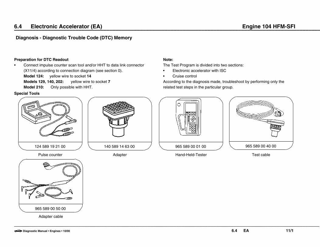
Preparation for DTC Readout• Connect impulse counter scan tool and/or HHT to data link connector
(X11/4) according to connection diagram (see section 0).Model 124: yellow wire to socket 14Models 129, 140, 202: yellow wire to socket 7Model 210: Only possible with HHT.
Note:The Test Program is divided into two sections:• Electronic accelerator with ISC• Cruise controlAccording to the diagnosis made, troubleshoot by performing only therelated test steps in the particular group.
Special Tools
Pulse counter
124 589 19 21 00
Adapter
140 589 14 63 00 965 589 00 01 00
Hand-Held-Tester
965 589 00 40 00
Test cable
Adapter cable
965 589 00 50 00
–––––––––––––––––––––––––––––––––––––––––––––––––––––––––––––––––––––––––––––––––––––––––––––––––––––––––––––––––––––––––––––––––––––––––––––––––––––––––––––––––––––––––––––––––––––––––––––––––––––––
b Diagnostic Manual • Engines • 10/00 6.4 EA 11/1

6.4 Electronic Accelerator (EA) Engine 104 HFM-SFI ––––––––––––––––––––––––––––––––––––––––––––––––––––––––––––––––––––––––––––––––––––––––––––––––––––
Diagnosis – Diagnostic Trouble Code (DTC) Memory
DTCN A
Possible cause Test step/Remedy 1)
I No fault in system –
2 002
006
007
008
009
025
EA/CC/ISC control module (N4/1)Safety contact switch (M16/1s1)Stop lamp switch (S9/1)Safety contact switch (M16/1s1)Cruise control switch (S40) OFFEA/CC/ISC control module (N4/1)Actual value potentiometer (M16/1r2)Starter lock-out/back-up lamp switch (S16/3) (transmission range recognition)Closed throttle position switch (S29/3)Engine speed (TNA) signalVehicle speed signal (VSS)Safety relay within EA/CC/ISC control module (N4/1)EA/CC/ISC control module (N4/1)Engine harness
N4/1 23O 5.0, 6.0 23O 4.0 23O 7.0 24O 1.0N4/1 23O 4.0 23O 12.0, 24O 3.0 23O 11.0 23O 14.0 23O 15.0, 16.0N4/1N4/1Check harness wire insulation.
037 Conditions for activation of EA/CC/ISC actuator (M16/1) not fulfilled. Conditions:Engine: OFFTransmission range: P/N
1) Observe Preparation for Test, see 22.
–––––––––––––––––––––––––––––––––––––––––––––––––––––––––––––––––––––––––––––––––––––––––––––––––––––––––––––––––––––––––––––––––––––––––––––––––––––––––––––––––––––––––––––––––––––––––––––––––––––––
b Diagnostic Manual • Engines • 10/00 6.4 EA 11/2

6.4 Electronic Accelerator (EA) Engine 104 HFM-SFI ––––––––––––––––––––––––––––––––––––––––––––––––––––––––––––––––––––––––––––––––––––––––––––––––––––
Diagnosis – Diagnostic Trouble Code (DTC) Memory
DTCN A
Possible cause Test step/Remedy 1)
3 054, 056
057
048
049
050
05I
052
053
055
EA/CC/ISC actuator (M16/1)Reference potentiometer (M16/1r1) (voltage supply)Reference potentiometer (M16/3r1)Actual value potentiometer (M16/3r2)Safety contact switch (M16/3s1)Closed throttle position switch (M16/1s2)Actuator motor (M16/1m1)Magnetic clutch (M16/1k1)Reset not accomplished (actuator adaptation)
23O 2.0– 10.0 23O 2.0 23O 3.0 23O 4.0 23O 7.0, 8.0 23O 6.0, 8.0 23O 9.0 23O 10.0Erase DTC:Ignition: OFFIgnition: ON (for at least 90 seconds).If DTC reappears:EA/CC/ISC actuator (M16/1)
4 064 CC switch (S40) 24O 1.0
5 080 Stop lamp switch (S9/1) 24O 2.0
6 096
097
Starter lock-out/backup lamp switch (S16/1)Not applicable to U.S. version vehicles
23O 12.0, 24O 3.0
1) Observe Preparation for Test, see 22.
–––––––––––––––––––––––––––––––––––––––––––––––––––––––––––––––––––––––––––––––––––––––––––––––––––––––––––––––––––––––––––––––––––––––––––––––––––––––––––––––––––––––––––––––––––––––––––––––––––––––
b Diagnostic Manual • Engines • 10/00 6.4 EA 11/3
6.4 Electronic Accelerator (EA) Engine 104 HFM-SFI ––––––––––––––––––––––––––––––––––––––––––––––––––––––––––––––––––––––––––––––––––––––––––––––––––––
Diagnosis – Diagnostic Trouble Code (DTC) Memory
DTCN A
Possible cause Test step/Remedy 1)
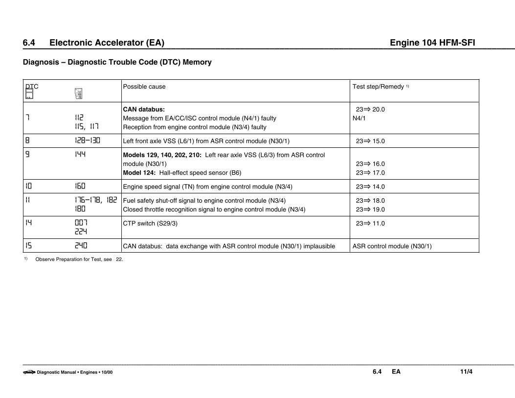
7 II2
II5, II7
CAN databus:Message from EA/CC/ISC control module (N4/1) faultyReception from engine control module (N3/4) faulty
23O 20.0N4/1
8 I28-I30 Left front axle VSS (L6/1) from ASR control module (N30/1) 23O 15.0
9 I44 Models 129, 140, 202, 210: Left rear axle VSS (L6/3) from ASR control module (N30/1)Model 124: Hall-effect speed sensor (B6)
23O 16.0 23O 17.0
I0 I60 Engine speed signal (TN) from engine control module (N3/4) 23O 14.0
II I76-I78, I82
I80
Fuel safety shut-off signal to engine control module (N3/4)Closed throttle recognition signal to engine control module (N3/4)
23O 18.0 23O 19.0
I4 007
224
CTP switch (S29/3) 23O 11.0
I5 240 CAN databus: data exchange with ASR control module (N30/1) implausible ASR control module (N30/1)
1) Observe Preparation for Test, see 22.
–––––––––––––––––––––––––––––––––––––––––––––––––––––––––––––––––––––––––––––––––––––––––––––––––––––––––––––––––––––––––––––––––––––––––––––––––––––––––––––––––––––––––––––––––––––––––––––––––––––––
b Diagnostic Manual • Engines • 10/00 6.4 EA 11/4

6.4 Electronic Accelerator (EA) Engine 104 HFM-SFI ––––––––––––––––––––––––––––––––––––––––––––––––––––––––––––––––––––––––––––––––––––––––––––––––––––Diagnosis – Complaint Related Diagnostic Chart
Complaint/Problem Possible cause Test step/Remedy 1)
Electronic accelerator in “limp-home” mode CTP switch (S29/3) 23 O 11.0
Engine speed limiter operates at 1200 rpm Fuel safety shut-off to engine control module (N3/4) 23 O 18.0
1) Observe Preparation for Test, see 22.
–––––––––––––––––––––––––––––––––––––––––––––––––––––––––––––––––––––––––––––––––––––––––––––––––––––––––––––––––––––––––––––––––––––––––––––––––––––––––––––––––––––––––––––––––––––––––––––––––––––––
b Diagnostic Manual • Engines • 10/00 6.4 EA 12/1
6.4 Electronic Accelerator (EA) Engine 104 HFM-SFI ––––––––––––––––––––––––––––––––––––––––––––––––––––––––––––––––––––––––––––––––––––––––––––––––––––Electrical Test Program – Component Locations
P30-5277-57
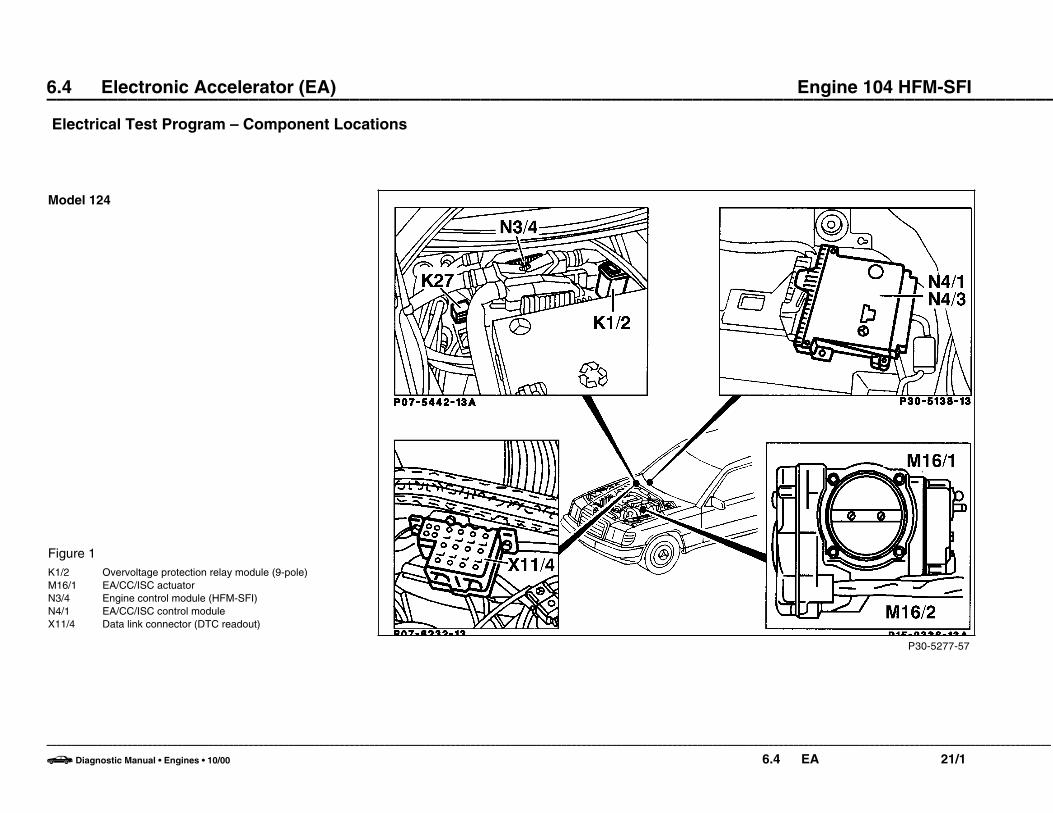
Model 124
Figure 1K1/2 Overvoltage protection relay module (9-pole)M16/1 EA/CC/ISC actuatorN3/4 Engine control module (HFM-SFI)N4/1 EA/CC/ISC control moduleX11/4 Data link connector (DTC readout)
–––––––––––––––––––––––––––––––––––––––––––––––––––––––––––––––––––––––––––––––––––––––––––––––––––––––––––––––––––––––––––––––––––––––––––––––––––––––––––––––––––––––––––––––––––––––––––––––––––––––
b Diagnostic Manual • Engines • 10/00 6.4 EA 21/1

6.4 Electronic Accelerator (EA) Engine 104 HFM-SFI ––––––––––––––––––––––––––––––––––––––––––––––––––––––––––––––––––––––––––––––––––––––––––––––––––––
Electrical Test Program – Component Locations
P30-5276-57
Model 124
Figure 2A1p8 Electronic speedometerS9/1 Stop lamp switch (ASR) (4-pole)S16/1 Starter lock-out/backup lamp switchS29/3 CTP switchS40 CC switch
V Decelerate/setB Accelerate/setSP ResumeA Off
–––––––––––––––––––––––––––––––––––––––––––––––––––––––––––––––––––––––––––––––––––––––––––––––––––––––––––––––––––––––––––––––––––––––––––––––––––––––––––––––––––––––––––––––––––––––––––––––––––––––
b Diagnostic Manual • Engines • 10/00 6.4 EA 21/2
6.4 Electronic Accelerator (EA) Engine 104 HFM-SFI ––––––––––––––––––––––––––––––––––––––––––––––––––––––––––––––––––––––––––––––––––––––––––––––––––––
Electrical Test Program – Component Locations
P30-5275-57
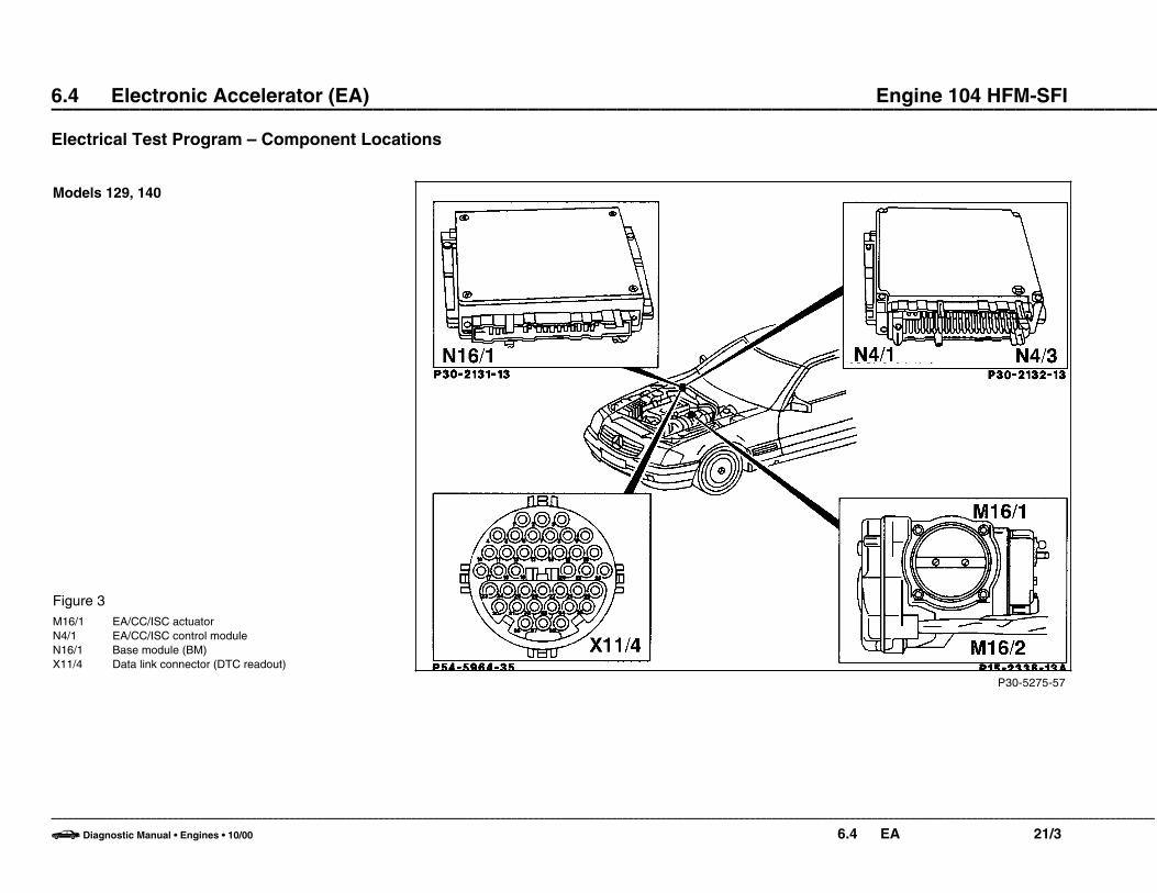
Models 129, 140
Figure 3M16/1 EA/CC/ISC actuatorN4/1 EA/CC/ISC control moduleN16/1 Base module (BM)X11/4 Data link connector (DTC readout)
–––––––––––––––––––––––––––––––––––––––––––––––––––––––––––––––––––––––––––––––––––––––––––––––––––––––––––––––––––––––––––––––––––––––––––––––––––––––––––––––––––––––––––––––––––––––––––––––––––––––
b Diagnostic Manual • Engines • 10/00 6.4 EA 21/3
6.4 Electronic Accelerator (EA) Engine 104 HFM-SFI ––––––––––––––––––––––––––––––––––––––––––––––––––––––––––––––––––––––––––––––––––––––––––––––––––––
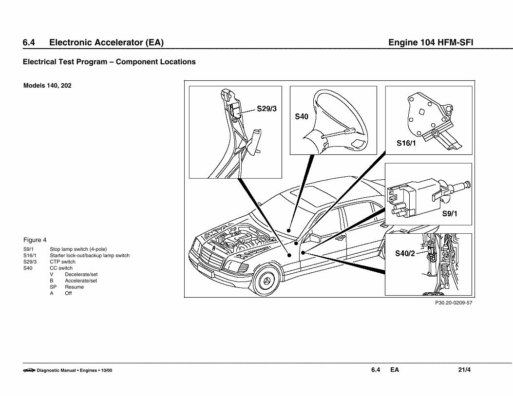
Electrical Test Program – Component Locations
P30.20-0209-57
Models 140, 202
Figure 4S9/1 Stop lamp switch (4-pole)S16/1 Starter lock-out/backup lamp switchS29/3 CTP switchS40 CC switch
V Decelerate/setB Accelerate/setSP ResumeA Off
–––––––––––––––––––––––––––––––––––––––––––––––––––––––––––––––––––––––––––––––––––––––––––––––––––––––––––––––––––––––––––––––––––––––––––––––––––––––––––––––––––––––––––––––––––––––––––––––––––––––
b Diagnostic Manual • Engines • 10/00 6.4 EA 21/4
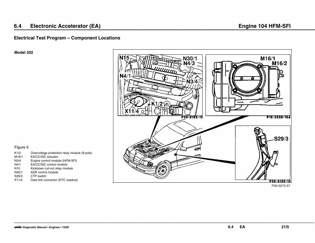
6.4 Electronic Accelerator (EA) Engine 104 HFM-SFI ––––––––––––––––––––––––––––––––––––––––––––––––––––––––––––––––––––––––––––––––––––––––––––––––––––
Electrical Test Program – Component Locations
P30-5273-57
Model 202
Figure 5K1/2 Overvoltage protection relay module (9-pole)M16/1 EA/CC/ISC actuatorN3/4 Engine control module (HFM-SFI)N4/1 EA/CC/ISC control moduleN15 Kickdown cut-out relay moduleN30/1 ASR control moduleS29/3 CTP switchX11/4 Data link connector (DTC readout)
–––––––––––––––––––––––––––––––––––––––––––––––––––––––––––––––––––––––––––––––––––––––––––––––––––––––––––––––––––––––––––––––––––––––––––––––––––––––––––––––––––––––––––––––––––––––––––––––––––––––
b Diagnostic Manual • Engines • 10/00 6.4 EA 21/5

6.4 Electronic Accelerator (EA) Engine 104 HFM-SFI ––––––––––––––––––––––––––––––––––––––––––––––––––––––––––––––––––––––––––––––––––––––––––––––––––––
Electrical Test Program – Component Locations
P30-5278-57
Model 202
Figure 6N22 A/C pushbutton control module (Automatic A/C)S9/1 Stop lamp switch (4-pole)S16/1 Starter lock-out/backup lamp switchS40 CC switch
V Decelerate/setB Accelerate/setSP ResumeA Off
–––––––––––––––––––––––––––––––––––––––––––––––––––––––––––––––––––––––––––––––––––––––––––––––––––––––––––––––––––––––––––––––––––––––––––––––––––––––––––––––––––––––––––––––––––––––––––––––––––––––
b Diagnostic Manual • Engines • 10/00 6.4 EA 21/6

6.4 Electronic Accelerator (EA) Engine 104 HFM-SFI ––––––––––––––––––––––––––––––––––––––––––––––––––––––––––––––––––––––––––––––––––––––––––––––––––––
Electrical Test Program – Component Locations
P30.20-0208-57
Model 210
Figure 7N4/1 EA/CC/ISC control moduleS9/1 Stop lamp switch (4-pole)S16/1 Starter lock-out/backup lamp switchS40 CC switch
V Decelerate/setB Accelerate/setSP ResumeA Off
–––––––––––––––––––––––––––––––––––––––––––––––––––––––––––––––––––––––––––––––––––––––––––––––––––––––––––––––––––––––––––––––––––––––––––––––––––––––––––––––––––––––––––––––––––––––––––––––––––––––
b Diagnostic Manual • Engines • 10/00 6.4 EA 21/7
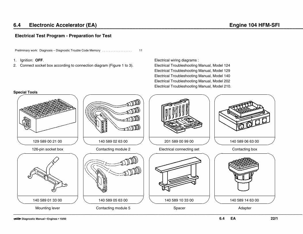
6.4 Electronic Accelerator (EA) Engine 104 HFM-SFI ––––––––––––––––––––––––––––––––––––––––––––––––––––––––––––––––––––––––––––––––––––––––––––––––––––Electrical Test Program - Preparation for Test
Preliminary work: Diagnosis – Diagnostic Trouble Code Memory . . . . . . . . . . . . . . . . . . 11
1. Ignition: OFF.2. Connect socket box according to connection diagram (Figure 1 to 3).
Electrical wiring diagrams :Electrical Troubleshooting Manual, Model 124Electrical Troubleshooting Manual, Model 129Electrical Troubleshooting Manual, Model 140Electrical Troubleshooting Manual, Model 202Electrical Troubleshooting Manual, Model 210.
Special Tools
126-pin socket box
129 589 00 21 00
Contacting module 2
140 589 02 63 00
Electrical connecting set
201 589 00 99 00
Contacting box
140 589 06 63 00
Mounting lever
140 589 01 33 00
Contacting module 5
140 589 05 63 00
Spacer
140 589 10 33 00
Adapter
140 589 14 63 00
–––––––––––––––––––––––––––––––––––––––––––––––––––––––––––––––––––––––––––––––––––––––––––––––––––––––––––––––––––––––––––––––––––––––––––––––––––––––––––––––––––––––––––––––––––––––––––––––––––––––
b Diagnostic Manual • Engines • 10/00 6.4 EA 22/1

6.4 Electronic Accelerator (EA) Engine 104 HFM-SFI ––––––––––––––––––––––––––––––––––––––––––––––––––––––––––––––––––––––––––––––––––––––––––––––––––––Electrical Test Program - Preparation for Test
Special Tools
35-pin socket box
124 589 00 21 00
43-pin test cable
124 589 50 63 00
Electrical connecting set
201 589 00 99 00
Conventional tools, test equipment
Description Brand, model, etc.
Multimeter 1) Fluke models 23, 83, 85, 87
1) Available through the MBUSA Standard Equipment Program.
–––––––––––––––––––––––––––––––––––––––––––––––––––––––––––––––––––––––––––––––––––––––––––––––––––––––––––––––––––––––––––––––––––––––––––––––––––––––––––––––––––––––––––––––––––––––––––––––––––––––
b Diagnostic Manual • Engines • 10/00 6.4 EA 22/2
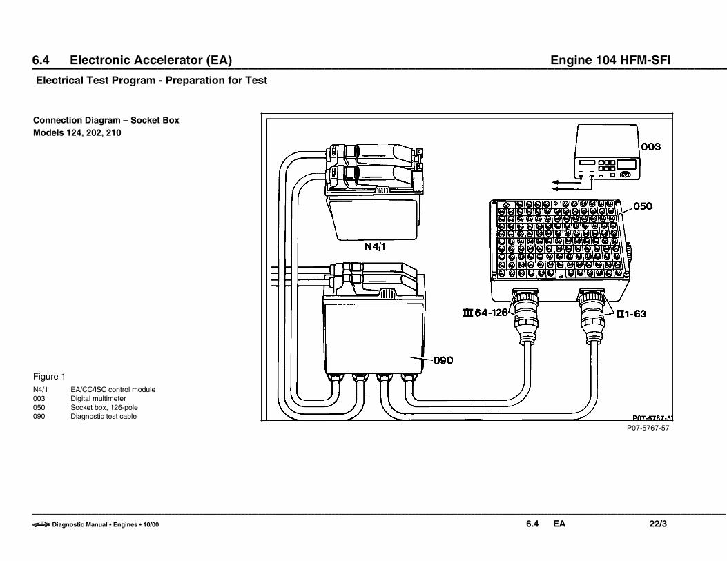
6.4 Electronic Accelerator (EA) Engine 104 HFM-SFI ––––––––––––––––––––––––––––––––––––––––––––––––––––––––––––––––––––––––––––––––––––––––––––––––––––Electrical Test Program - Preparation for Test
P07-5767-57
Connection Diagram – Socket BoxModels 124, 202, 210
Figure 1N4/1 EA/CC/ISC control module003 Digital multimeter050 Socket box, 126-pole090 Diagnostic test cable
–––––––––––––––––––––––––––––––––––––––––––––––––––––––––––––––––––––––––––––––––––––––––––––––––––––––––––––––––––––––––––––––––––––––––––––––––––––––––––––––––––––––––––––––––––––––––––––––––––––––
b Diagnostic Manual • Engines • 10/00 6.4 EA 22/3

6.4 Electronic Accelerator (EA) Engine 104 HFM-SFI ––––––––––––––––––––––––––––––––––––––––––––––––––––––––––––––––––––––––––––––––––––––––––––––––––––Electrical Test Program - Preparation for Test
P30-5191-57
Connection Diagram – Socket BoxModel 129
Figure 2F23 Module boxN4/1 EA/CC/ISC control moduleX11/4 Data link connector (DTC readout)003 Digital multimeter050 Socket box, 126-pole070 Contact box072 Contact module 2
bl blue
–––––––––––––––––––––––––––––––––––––––––––––––––––––––––––––––––––––––––––––––––––––––––––––––––––––––––––––––––––––––––––––––––––––––––––––––––––––––––––––––––––––––––––––––––––––––––––––––––––––––
b Diagnostic Manual • Engines • 10/00 6.4 EA 22/4

6.4 Electronic Accelerator (EA) Engine 104 HFM-SFI ––––––––––––––––––––––––––––––––––––––––––––––––––––––––––––––––––––––––––––––––––––––––––––––––––––Electrical Test Program - Preparation for Test
P30-5193-57
Connection Diagram – Socket BoxModel 140
Figure 3F23 Module boxN4/1 EA/CC/ISC control moduleX11/4 Data link connector (DTC readout)003 Digital multimeter050 Socket box, 126-pole070 Contact box072 Contact module 2
bl blue
–––––––––––––––––––––––––––––––––––––––––––––––––––––––––––––––––––––––––––––––––––––––––––––––––––––––––––––––––––––––––––––––––––––––––––––––––––––––––––––––––––––––––––––––––––––––––––––––––––––––
b Diagnostic Manual • Engines • 10/00 6.4 EA 22/5
6.4 Electronic Accelerator (EA) Engine 104 HFM-SFI ––––––––––––––––––––––––––––––––––––––––––––––––––––––––––––––––––––––––––––––––––––––––––––––––––––Electrical Test Program - Preparation for Test
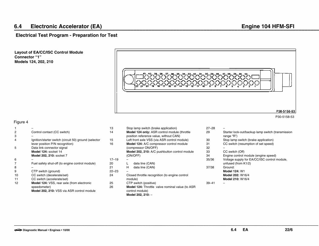
P30-5158-53
Layout of EA/CC/ISC Control ModuleConnector “1” Models 124, 202, 210
Figure 4
13 Stop lamp switch (brake application)14 Model 124 only: ASR control module (throttle
position reference value, without CAN)15 Left front axle VSS (via ASR control module)16 Model 124: A/C compressor control module
(compressor ON/OFF)Model 202, 210: A/C pushbutton control module(ON/OFF)
17–19 –20 L data line (CAN)21 H data line (CAN)22–23 –24 Closed throttle recognition (to engine control
module)25 CTP switch (positive)26 Model 124: Throttle valve nominal value (to ASR
control module)Model 202, 210: –
1 –2 Control contact (CC switch)3 –4 Ignition/starter switch (circuit 50) ground (selector
lever position P/N recognition)5 Data link connector signal
Model 124: socket 14Model 202, 210: socket 7
6 –7 Fuel safety shut-off (to engine control module)8 –9 CTP switch (ground)10 CC switch (decelerate/set)11 CC switch (accelerate/set)12 Model 124: VSS, rear axle (from electronic
speedometer)Model 202, 210: VSS via ASR control module
27–28 –29 Starter lock-out/backup lamp switch (transmission
range “R”)30 Stop lamp switch (brake application)31 CC switch (resumption of set speed)32 –33 CC switch (Off)34 Engine control module (engine speed)35/36 Voltage supply for EA/CC/ISC control module,
unfused (from K1/2)37/38 Ground:
Model 124: W1Model 202: W16/4Model 210: W16/4
39–41 –
–––––––––––––––––––––––––––––––––––––––––––––––––––––––––––––––––––––––––––––––––––––––––––––––––––––––––––––––––––––––––––––––––––––––––––––––––––––––––––––––––––––––––––––––––––––––––––––––––––––––
b Diagnostic Manual • Engines • 10/00 6.4 EA 22/6
6.4 Electronic Accelerator (EA) Engine 104 HFM-SFI ––––––––––––––––––––––––––––––––––––––––––––––––––––––––––––––––––––––––––––––––––––––––––––––––––––Electrical Test Program - Preparation for Test
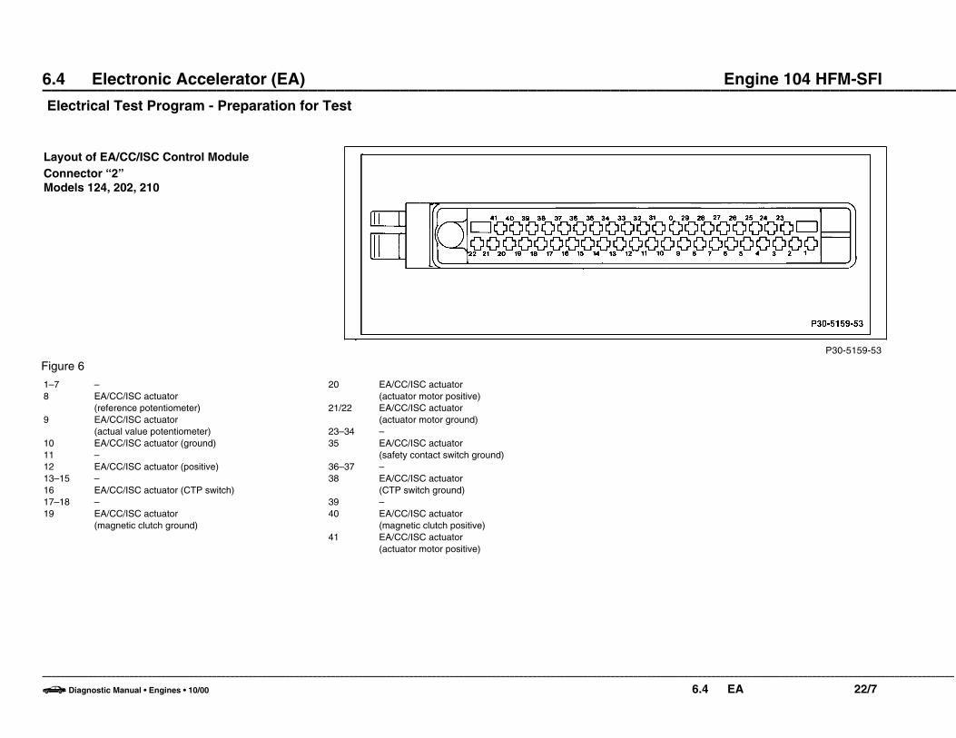
P30-5159-53
Layout of EA/CC/ISC Control ModuleConnector “2”Models 124, 202, 210
Figure 6
20 EA/CC/ISC actuator (actuator motor positive)
21/22 EA/CC/ISC actuator (actuator motor ground)
23–34 –35 EA/CC/ISC actuator
(safety contact switch ground)36–37 –38 EA/CC/ISC actuator
(CTP switch ground)39 –40 EA/CC/ISC actuator
(magnetic clutch positive)41 EA/CC/ISC actuator
(actuator motor positive)
1–7 –8 EA/CC/ISC actuator
(reference potentiometer)9 EA/CC/ISC actuator
(actual value potentiometer)10 EA/CC/ISC actuator (ground)11 –12 EA/CC/ISC actuator (positive)13–15 –16 EA/CC/ISC actuator (CTP switch)17–18 –19 EA/CC/ISC actuator
(magnetic clutch ground)
–––––––––––––––––––––––––––––––––––––––––––––––––––––––––––––––––––––––––––––––––––––––––––––––––––––––––––––––––––––––––––––––––––––––––––––––––––––––––––––––––––––––––––––––––––––––––––––––––––––––
b Diagnostic Manual • Engines • 10/00 6.4 EA 22/7

6.4 Electronic Accelerator (EA) Engine 104 HFM-SFI ––––––––––––––––––––––––––––––––––––––––––––––––––––––––––––––––––––––––––––––––––––––––––––––––––––Electrical Test Program - Preparation for Test
P07-5171-53
Layout of EA/CC/ISC Control ModuleConnector “1” Models 129, 140
Figure 7
13 Stop lamp switch (brake application)14 –15 Left front axle VSS signal from ASR control module16 Base module (compressor ON/OFF)17–23 –24 Engine control module (closed throttle recognition)25 CTP switch (positive)26–28 –29 Starter lock-out/backup lamp switch (transmission
range “R”)30 Brake application (from stop lamp switch)31 Resumption of stored speed (from CC switch)32 –
1 –2 CC switch3 –4 Ignition/starter switch (circuit 50) ground (selector
lever position P/N recognition)5 Data link connector (socket 7)6 –7 Engine control module, fuel safety shut-off 8 –9 CTP switch (ground)10 CC switch (decelerate/set)11 CC switch (accelerate/set)12 Left rear axle VSS signal from ASR control module
33 CC switch (Off)34 Engine rpm (from engine control module)35/36 EA control module voltage supply, unfused (from
base module)37/38 Ground:
Model 129: W27Model 140: W15
L Data line (CAN)H Data line (CAN)F23 Modulbox
–––––––––––––––––––––––––––––––––––––––––––––––––––––––––––––––––––––––––––––––––––––––––––––––––––––––––––––––––––––––––––––––––––––––––––––––––––––––––––––––––––––––––––––––––––––––––––––––––––––––
b Diagnostic Manual • Engines • 10/00 6.4 EA 22/8

6.4 Electronic Accelerator (EA) Engine 104 HFM-SFI ––––––––––––––––––––––––––––––––––––––––––––––––––––––––––––––––––––––––––––––––––––––––––––––––––––Electrical Test Program - Preparation for Test
P07-5170-53
Layout of EA/CC/ISC Control ModuleConnector “2”Models 129, 140
Figure 7
21/22 EA/CC/ISC actuator (actuator motor ground)
23–34 –35 EA/CC/ISC actuator
(safety contact switch ground)36–37 –38 EA/CC/ISC actuator
(CTP switch ground)39 –40 EA/CC/ISC actuator
(magnetic clutch positive)41 EA/CC/ISC actuator
(actuator motor positive)L Data line (CAN)H Data line (CAN)F23 Modulbox
1–7 –8 EA/CC/ISC actuator
(reference potentiometer)9 EA/CC/ISC actuator
(actual value potentiometer)10 EA/CC/ISC actuator (ground)11 –12 EA/CC/ISC actuator (positive)13–15 –16 EA/CC/ISC actuator
(CTP switch, positive)17–18 –19 EA/CC/ISC actuator
(magnetic clutch ground)20 EA/CC/ISC actuator
(actuator motor positive)
–––––––––––––––––––––––––––––––––––––––––––––––––––––––––––––––––––––––––––––––––––––––––––––––––––––––––––––––––––––––––––––––––––––––––––––––––––––––––––––––––––––––––––––––––––––––––––––––––––––––
b Diagnostic Manual • Engines • 10/00 6.4 EA 22/9

6.4 Electronic Accelerator (EA) Engine 104 HFM-SFI
Electrical Test Program – Test
O A Test scope Test connection Test condition Nominal value Possible cause/Remedy
1.0 EA/CC/ISC control module (N4/1)Voltage supplyCircuit 87 unfusedModel 124, 202, 210
Model 129, 140
37 w(1.37)
38(1.38)
78(1.37)
79(1.38)
N4/1E
c
c
N4/1E
c
c
L 35(1.35)
36(1.36)
76(1.35)
77(1.36)
Ignition: ON 11 – 14 V O 1.1,
Model 124, 202Fuse on overvoltage protectionrelay module (K1/2)
Model 129, 140Base module (N16/1) seeDiagnostic Manual, Chassis andDrivrtrain, Vol. 1 – 1.1
Model 210Relay module (K40) seeDiagnostic Manual, Chassis andDrivrtrain, Vol. 1 – 1.1
–––––––––––––––––––––––––––––––––––––––––––––––––––––––––––––––––––––––––––––––––––––––––––––––––––––––––––––––––––––––––––––––––––––––––––––––––––––––––––––––––––––––––––––––––––––––––––––––––––––––
b Diagnostic Manual • Engines • 10/00 6.4 EA 23/1

6.4 Electronic Accelerator (EA) Engine 104 HFM-SFI
Electrical Test Program – Test
O A Test scope Test connection Test condition Nominal value Possible cause/Remedy
1.1 GroundModel 124Main ground (W1) (behind instrument cluster)
Model 129Ground on module boxbracket (W27)Model 140Ground in right footwell(W15)
Model 202Ground in right componentcompartment (W16/4)Model 210Output ground on right wheelwell (W16/4)
N4/1E37 w(1.37)
38 (1.38)
N4/1E78 w(1.37)
79 (1.38)
N4/1E37 w(1.37)
38 (1.38)
c
c
c
c
c
c
X11/4L 16
L 16
X11/4L 3
L 3
X11/4L 3
L 3
Ignition: ON
Ignition: OFF
Ignition: OFF
11 – 14 V Wiring,Model 124: W1Model 129: W27Model 140: W15Model 202: W16/4Model 210: W16/4
–––––––––––––––––––––––––––––––––––––––––––––––––––––––––––––––––––––––––––––––––––––––––––––––––––––––––––––––––––––––––––––––––––––––––––––––––––––––––––––––––––––––––––––––––––––––––––––––––––––––
b Diagnostic Manual • Engines • 10/00 6.4 EA 23/2

6.4 Electronic Accelerator (EA) Engine 104 HFM-SFI
Electrical Test Program – Test
O A Test scope Test connection Test condition Nominal value Possible cause/Remedy
2.0 054
056
EA/CC/ISC actuator (M16/1)Voltage supplyReference potentiometer(M16/1r1) andActual value potentiometer(M16/1r2)Model 124, 202, 210
Model 129, 140
37 w(1.37)
78 w(1.37)
N4/1E
c
N4/1E
c
L 75(2.12)
L 12(2.12)
Ignition: ON 4.7 – 5.3 VReferencevalue fortables I or II
Wiring,EA/CC/ISC actuator (M16/1).
3.0 048 EA/CC/ISC actuator (M16/1)Reference potentiometer(M16/1r1) signalModel 124, 202, 210
Model 129, 140
37 w(1.37)
78 w(1.37)
N4/1E
c
N4/1E
c
L 71(2.8)
L 8(2.8)
Ignition: ONAccelerator pedal position:Closed throttle position
Wide open throttle orKickdown
Table IColumn “a”
Column “b”
Wiring,EA/CC/ISC actuator (M16/1).
–––––––––––––––––––––––––––––––––––––––––––––––––––––––––––––––––––––––––––––––––––––––––––––––––––––––––––––––––––––––––––––––––––––––––––––––––––––––––––––––––––––––––––––––––––––––––––––––––––––––
b Diagnostic Manual • Engines • 10/00 6.4 EA 23/3
6.4 Electronic Accelerator (EA) Engine 104 HFM-SFI
Electrical Test Program – Test
O A Test scope Test connection Test condition Nominal value Possible cause/Remedy
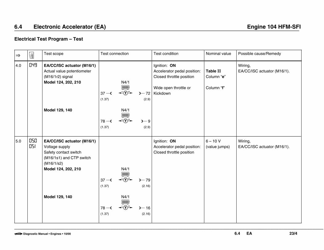
4.0 049 EA/CC/ISC actuator (M16/1)Actual value potentiometer(M16/1r2) signalModel 124, 202, 210
Model 129, 140
37 w(1.37)
78 w(1.37)
N4/1E
c
N4/1E
c
L 72(2.9)
L 9(2.9)
Ignition: ONAccelerator pedal position:Closed throttle position
Wide open throttle orKickdown
Table II
Column “e”
Column “f”
Wiring,EA/CC/ISC actuator (M16/1).
5.0 050
05I
EA/CC/ISC actuator (M16/1)Voltage supplySafety contact switch(M16/1s1) and CTP switch(M16/1/s2)Model 124, 202, 210
Model 129, 140
37 w(1.37)
78 w(1.37)
N4/1E
c
N4/1E
c
L 79(2.16)
L 16(2.16)
Ignition: ONAccelerator pedal position:Closed throttle position
6 – 10 V(value jumps)
Wiring,EA/CC/ISC actuator (M16/1).
–––––––––––––––––––––––––––––––––––––––––––––––––––––––––––––––––––––––––––––––––––––––––––––––––––––––––––––––––––––––––––––––––––––––––––––––––––––––––––––––––––––––––––––––––––––––––––––––––––––––
b Diagnostic Manual • Engines • 10/00 6.4 EA 23/4

6.4 Electronic Accelerator (EA) Engine 104 HFM-SFI
Electrical Test Program – Test
O A Test scope Test connection Test condition Nominal value Possible cause/Remedy
6.0 05I EA/CC/ISC actuator (M16/1)CTP switch (M16/1s2)switching pointModel 124, 202, 210
Model 129, 140
73 w(2,10)
37 w(1.37)
10 w(2,10)
78 w(1.37)
N4/1E
c
N4/1E
c
N4/1E
c
N4/1E
c
L 75(2.12)
L 101(2.38)
L 12(2.12)
L 38(2.38)
Ignition: ONAccelerator pedal position:Closed throttle position
Connect secondmultimeter
Accelerator pedal position:Closed throttle position
Slowly depress acceleratorpedal until switching pointoccurs
4.7 – 5.3 VReferencevalue for TableIII.
Table III
Column “h” (value jumps)
Table III
Column “i”
Wiring,EA/CC/ISC actuator (M16/1).
–––––––––––––––––––––––––––––––––––––––––––––––––––––––––––––––––––––––––––––––––––––––––––––––––––––––––––––––––––––––––––––––––––––––––––––––––––––––––––––––––––––––––––––––––––––––––––––––––––––––
b Diagnostic Manual • Engines • 10/00 6.4 EA 23/5

6.4 Electronic Accelerator (EA) Engine 104 HFM-SFI
Electrical Test Program – Test
O A Test scope Test connection Test condition Nominal value Possible cause/Remedy
7.0 050 EA/CC/ISC actuator (M16/1)Safety contact switch(M16/1s1) switching pointModel 124, 202, 210
Model 129, 140
73 w(2,10)
37 w(1.37)
10 w(2,10)
78 w(1.37)
N4/1E
c
N4/1E
c
N4/1E
c
N4/1E
c
L 75(2.12)
L 98(2.35)
L 12(2.12)
L 35(2.35)
Ignition: ONAccelerator pedal position:Closed throttle position
Connect secondmultimeter
Accelerator pedal position:Closed throttle position
Slowly depress acceleratorpedal until switching pointoccurs
4.7 – 5.3 VReferencevalue for Table III.
Table IIIColumn “k”
Table IIIColumn “i” (value jumps)
Wiring,EA/CC/ISC actuator (M16/1).
–––––––––––––––––––––––––––––––––––––––––––––––––––––––––––––––––––––––––––––––––––––––––––––––––––––––––––––––––––––––––––––––––––––––––––––––––––––––––––––––––––––––––––––––––––––––––––––––––––––––
b Diagnostic Manual • Engines • 10/00 6.4 EA 23/6

6.4 Electronic Accelerator (EA) Engine 104 HFM-SFI
Electrical Test Program – Test
O A Test scope Test connection Test condition Nominal value Possible cause/Remedy
8.0 050
05I
EA/CC/ISC actuator (M16/1)CTP switch (M16/1s2) andsafety contact switch(M16/1s1)Model 124, 202, 210
Model 129, 140
98 w(2.35)
35 w(2.35)
N4/1E
c
N4/1E
c
L 101(2.38)
L 38(2.38)
Ignition: ONAccelerator pedal position:Closed throttle position
Slowly depress acceleratorby hand, until both contactswitches are closed(overlap point isimmeditaley after closedthrottle position)
Accelerator pedal position:Partial load or wide openthrottle
Positive voltagevalue (valuejumps)
<1 V
Negativevoltage value(value jumps)
Wiring,EA/CC/ISC actuator (M16/1).
–––––––––––––––––––––––––––––––––––––––––––––––––––––––––––––––––––––––––––––––––––––––––––––––––––––––––––––––––––––––––––––––––––––––––––––––––––––––––––––––––––––––––––––––––––––––––––––––––––––––
b Diagnostic Manual • Engines • 10/00 6.4 EA 23/7

6.4 Electronic Accelerator (EA) Engine 104 HFM-SFI
Electrical Test Program – Test
O A Test scope Test connection Test condition Nominal value Possible cause/Remedy
9.0 052 EA/CC/ISC actuator (M16/1)Actuator motor (M16/1m1)resistanceModel 124, 202, 210
Model 129, 140
84 w(2.21)
85 w(2.22)
21 w(2.21)
22 w(2.22)
N4/1E
b
b
N4/1E
b
b
L 83(2.20)
L 104(2.41)
L 20(2.20)
L 41(2.41)
Ignition: OFF
Models 124, 202, 210Disconnect connector 2from EA/CC/ISC controlmodule (N4/1)Accelerator pedal position:Closed throttle position
Models 129, 140Disconnect EA/CC/ISCcontrol module (N4/1)
Accelerator pedal position:Closed throttle position
<10 ]
<10 ]
Wirng,EA/CC/ISC actuator (M16/1).
–––––––––––––––––––––––––––––––––––––––––––––––––––––––––––––––––––––––––––––––––––––––––––––––––––––––––––––––––––––––––––––––––––––––––––––––––––––––––––––––––––––––––––––––––––––––––––––––––––––––
b Diagnostic Manual • Engines • 10/00 6.4 EA 23/8

6.4 Electronic Accelerator (EA) Engine 104 HFM-SFI
Electrical Test Program – Test
O A Test scope Test connection Test condition Nominal value Possible cause/Remedy
10.0 053 EA/CC/ISC actuator (M16/1)Magnetic clutch (M16/1k1)Model 124, 202, 210
Model 129, 140
82 w(2.19)
19 w(2.19)
N4/1E
c
N4/1E
c
L 103(2.40)
L 40(2.40)
Ignition: ON 7.5 – 10 V Wiring,EA/CC/ISC actuator (M16/1),EA/CC/ISC control module (N4/1).
–––––––––––––––––––––––––––––––––––––––––––––––––––––––––––––––––––––––––––––––––––––––––––––––––––––––––––––––––––––––––––––––––––––––––––––––––––––––––––––––––––––––––––––––––––––––––––––––––––––––
b Diagnostic Manual • Engines • 10/00 6.4 EA 23/9

6.4 Electronic Accelerator (EA) Engine 104 HFM-SFI
Electrical Test Program – Test
O A Test scope Test connection Test condition Nominal value Possible cause/Remedy
11.0 224 CTP switch (S29/3)Voltage supplyModel 124, 202, 210
Signal
Model 129, 140
37 w(1.37)
37 w(1.37)
78 w(1.37)
78 w(1.37)
N4/1E
c
N4/1E
c
N4/1E
c
N4/1E
c
L 25(1.25)
L 9(1.9)
L 66(1.25)
L 50(1.9)
Ignition: ON
Accelerator pedal position:Closed throttle position
Slowly depress acceleratorpedal until switching pointoccurs.
4.0 – 5.5 V
< 1 V
1.0 – 2.25 V
Wiring,CTP switch (S29/3),O 11.1.
–––––––––––––––––––––––––––––––––––––––––––––––––––––––––––––––––––––––––––––––––––––––––––––––––––––––––––––––––––––––––––––––––––––––––––––––––––––––––––––––––––––––––––––––––––––––––––––––––––––––
b Diagnostic Manual • Engines • 10/00 6.4 EA 23/10
6.4 Electronic Accelerator (EA) Engine 104 HFM-SFI
Electrical Test Program – Test
O A Test scope Test connection Test condition Nominal value Possible cause/Remedy
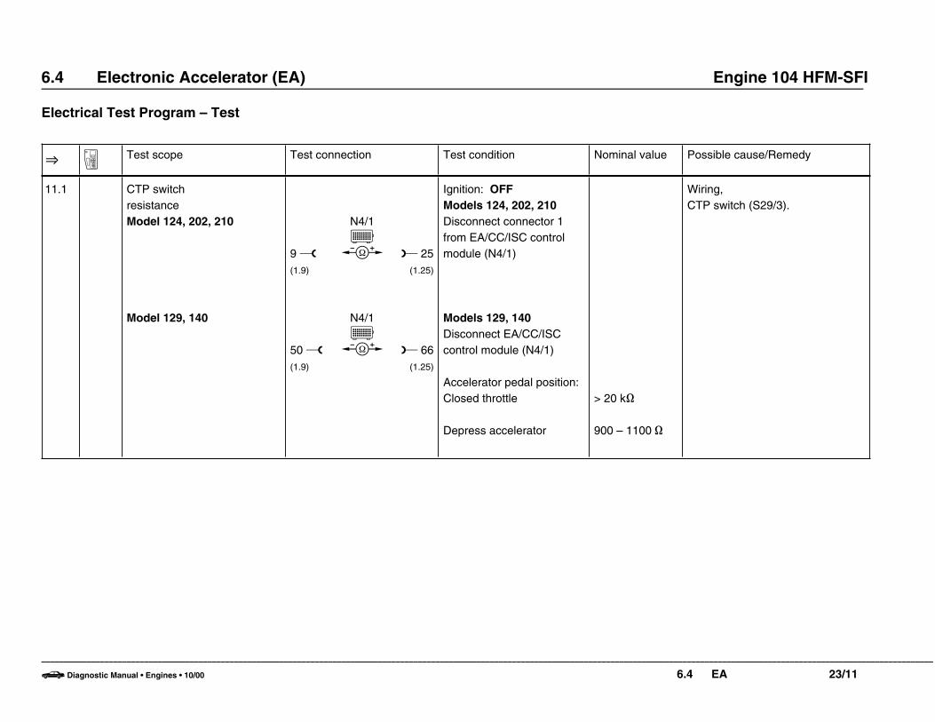
11.1 CTP switch resistanceModel 124, 202, 210
Model 129, 140
9 w(1.9)
50 w(1.9)
N4/1E
b
N4/1E
b
L 25(1.25)
L 66(1.25)
Ignition: OFFModels 124, 202, 210Disconnect connector 1from EA/CC/ISC controlmodule (N4/1)
Models 129, 140Disconnect EA/CC/ISCcontrol module (N4/1)
Accelerator pedal position:Closed throttle
Depress accelerator
> 20 k]
900 – 1100 ]
Wiring,CTP switch (S29/3).
–––––––––––––––––––––––––––––––––––––––––––––––––––––––––––––––––––––––––––––––––––––––––––––––––––––––––––––––––––––––––––––––––––––––––––––––––––––––––––––––––––––––––––––––––––––––––––––––––––––––
b Diagnostic Manual • Engines • 10/00 6.4 EA 23/11

6.4 Electronic Accelerator (EA) Engine 104 HFM-SFI
Electrical Test Program – Test
O A Test scope Test connection Test condition Nominal value Possible cause/Remedy
12.0 096 Starter lock-out/backuplamp switch (S16/1)Selector lever positionrecognitionModel 124, 202, 210
Model 129, 140
4 w(1.4)
37 w(1.37)
45 w(1.4)
78 w(1.37)
N4/1E
c
N4/1E
c
N4/1E
c
N4/1E
c
L 35(1.35)
L 29(1.29)
L 76(1.35)
L 70(1.29)
Ignition: ON
Transmission range:P/N
R/D/3/2
Transmission range:R
P/N/D/3/2
Transmission range:P/N
R/D/3/2
Transmission range:R
P/N/D/3/2
11 – 14 V< 1 V
11 – 14 V< 1 V
11 – 14 V< 1 V
11 – 14 V< 1 V
Wiring,Starter lock-out/backup lampswitch (S16/1).
–––––––––––––––––––––––––––––––––––––––––––––––––––––––––––––––––––––––––––––––––––––––––––––––––––––––––––––––––––––––––––––––––––––––––––––––––––––––––––––––––––––––––––––––––––––––––––––––––––––––
b Diagnostic Manual • Engines • 10/00 6.4 EA 23/12

6.4 Electronic Accelerator (EA) Engine 104 HFM-SFI
Electrical Test Program – Test
O A Test scope Test connection Test condition Nominal value Possible cause/Remedy
13.0 EA/CC/ISC controlmodule (N4/1)A/C compressor signalModel 124, 202, 210
Model 129, 140
38 w(1.38)
78 w(1.37)
N4/1E
c
N4/1E
c
L 16(1.16)
L 57(1.16)
Engine: StartClosed throttle position
Set temperature selector to MIN, blower speed tohighest setting
<1 V
11 – 14 V
Wiring,Models 124A/C compressor control module (N6),Model 202, 210Pushbutton control module (N22)Models 129, 140Base module (N16/1),DM Chassis & Drivetrain, Vol. 1section1.1
14.0 I60 EA/CC/ISC controlmodule (N4/1)Engine RPM (TN) signal fromengine control module (N3/4)Model 124, 202, 210
Model 129, 140
37 w(1.37)
78 w(1.37)
N4/1E
c
N4/1E
c
L 34(1.34)
L 75(1.34)
Engine: StartClosed throttle position 5 – 12 V
Wiring,Models 124, 202, 210Engine control module (N3/4),Models 129, 140Base module (N16/1).
–––––––––––––––––––––––––––––––––––––––––––––––––––––––––––––––––––––––––––––––––––––––––––––––––––––––––––––––––––––––––––––––––––––––––––––––––––––––––––––––––––––––––––––––––––––––––––––––––––––––
b Diagnostic Manual • Engines • 10/00 6.4 EA 23/13
6.4 Electronic Accelerator (EA) Engine 104 HFM-SFI
Electrical Test Program – Test
O A Test scope Test connection Test condition Nominal value Possible cause/Remedy
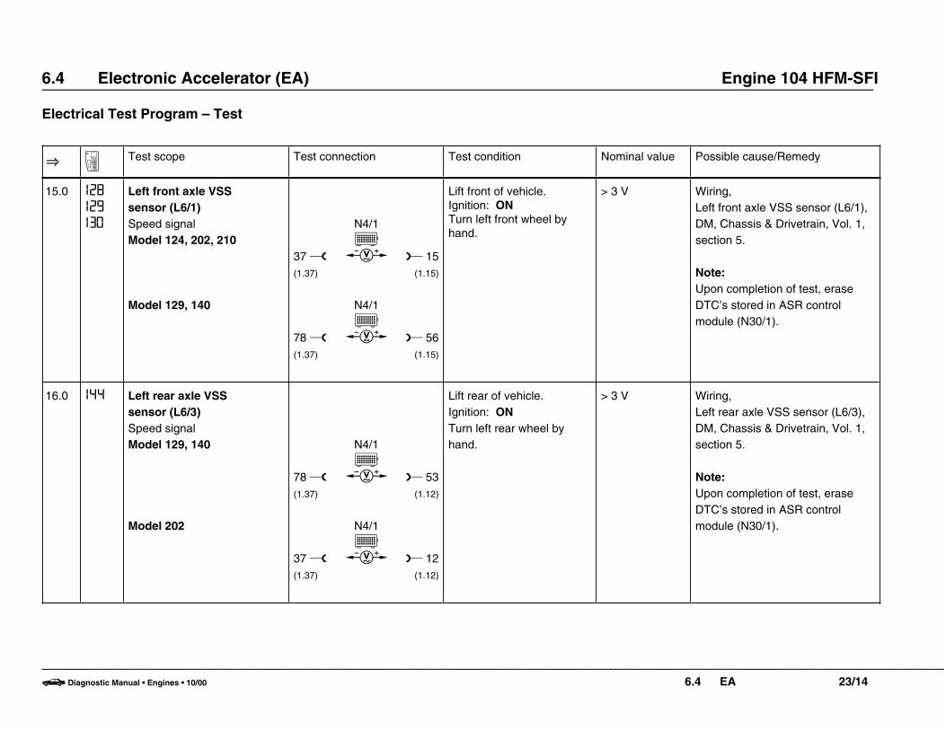
15.0 I28
I29
I30
Left front axle VSSsensor (L6/1)Speed signalModel 124, 202, 210
Model 129, 140
37 w(1.37)
78 w(1.37)
N4/1E
f
N4/1E
f
L 15(1.15)
L 56(1.15)
Lift front of vehicle.Ignition: ONTurn left front wheel byhand.
> 3 V Wiring,Left front axle VSS sensor (L6/1),DM, Chassis & Drivetrain, Vol. 1,section 5.
Note:Upon completion of test, eraseDTC’s stored in ASR controlmodule (N30/1).
16.0 I44 Left rear axle VSS sensor (L6/3)Speed signalModel 129, 140
Model 202
78 w(1.37)
37 w(1.37)
N4/1E
f
N4/1E
f
L 53(1.12)
L 12(1.12)
Lift rear of vehicle.Ignition: ONTurn left rear wheel byhand.
> 3 V Wiring,Left rear axle VSS sensor (L6/3),DM, Chassis & Drivetrain, Vol. 1,section 5.
Note:Upon completion of test, eraseDTC’s stored in ASR controlmodule (N30/1).
–––––––––––––––––––––––––––––––––––––––––––––––––––––––––––––––––––––––––––––––––––––––––––––––––––––––––––––––––––––––––––––––––––––––––––––––––––––––––––––––––––––––––––––––––––––––––––––––––––––––
b Diagnostic Manual • Engines • 10/00 6.4 EA 23/14

6.4 Electronic Accelerator (EA) Engine 104 HFM-SFI
Electrical Test Program – Test
O A Test scope Test connection Test condition Nominal value Possible cause/Remedy
[16.0] 9 Model 210
37 w(1.37)
N4/1E
c L 12(1.12)
M Caution!On model 210 setmultimeter to DC voltage.
> 3 V
17.0 9 Model 124 onlyHall-effect speed sensor(B6)Speed signal
37 w(1.37)
N4/1E
c L 12(1.12)
Ignition: ONRoll vehicle 3 ft. (1 meter)or drive vehicle ondynamometer above 13mph (20 km/h).
Value jumps0 – 12 Vwithoutconsumersturned on.
0 – 9 V withconsumersturned on.
Wiring,B6
18.0 II EA/CC/ISC control module (N4/1)Fuel safety shut-off signal toEngine control module (N3/4)Model 124, 202, 210
Model 129, 140
38 w(1.38)
78 w(1.37)
N4/1E
c
N4/1E
c
L 7(1.7)
L 48(1.7)
Ignition: ON 2.0 – 11 V(value jumps).
Wiring,Throttle valve actuator (M16/6),N4/1
–––––––––––––––––––––––––––––––––––––––––––––––––––––––––––––––––––––––––––––––––––––––––––––––––––––––––––––––––––––––––––––––––––––––––––––––––––––––––––––––––––––––––––––––––––––––––––––––––––––––
b Diagnostic Manual • Engines • 10/00 6.4 EA 23/15

6.4 Electronic Accelerator (EA) Engine 104 HFM-SFI
Electrical Test Program – Test
O A Test scope Test connection Test condition Nominal value Possible cause/Remedy
19.0 EA/CC/ISC control module (N4/1)Closed throttle positionrecognition signal to enginecontrol module (N3/4)Model 124, 202, 210
Model 129, 140
37 w(1.37)
78 w(1.37)
N4/1E
c
N4/1E
c
L 24(1.24)
L 65(1.24)
Ignition: ONAccelerator pedal position:Closed throttle position
Depress accelerator pedal
4.8 V
5.5 V
Wiring,N4/1
20.0 7 CAN data busModel 124, 202, 210
Model 129, 140
20 w(1.20)
"L" w
N4/1E
b
N4/1x1E
b
L 21(1.21)
L “H“
Ignition: OFF
Ignition: OFFDisconnect EA/CC/ISCcontrol module (N4/1).Measure resistance onconnector.
40–65 ]
115–125 ]
Wiring,Models 124, 202, 210Engine control module (N3/4),N4/1,
Models 129, 140Engine control module (N3/4),DM, Engines Vol. 2, section 1.1.
–––––––––––––––––––––––––––––––––––––––––––––––––––––––––––––––––––––––––––––––––––––––––––––––––––––––––––––––––––––––––––––––––––––––––––––––––––––––––––––––––––––––––––––––––––––––––––––––––––––––
b Diagnostic Manual • Engines • 10/00 6.4 EA 23/16
6.4 Electronic Accelerator (EA) Engine 104 HFM-SFI
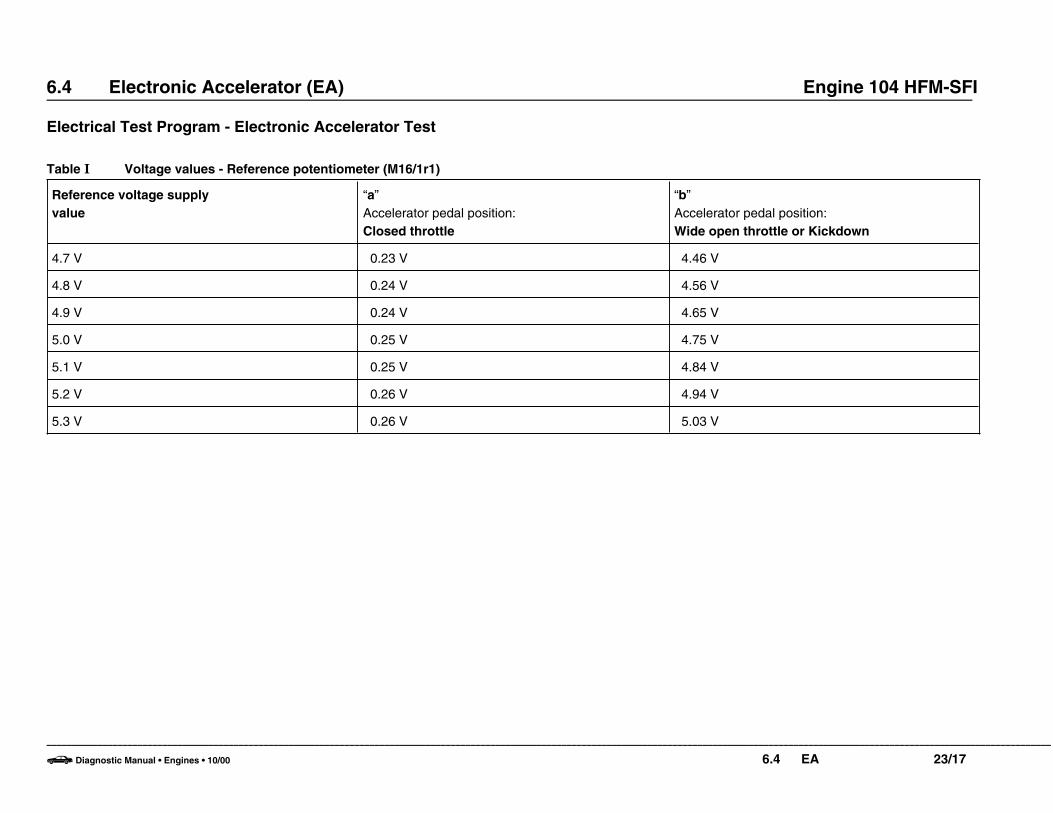
Electrical Test Program - Electronic Accelerator Test
Table I Voltage values - Reference potentiometer (M16/1r1)
Reference voltage supplyvalue
“a”Accelerator pedal position:Closed throttle
“b”Accelerator pedal position:Wide open throttle or Kickdown
4.7 V 0.23 V 4.46 V
4.8 V 0.24 V 4.56 V
4.9 V 0.24 V 4.65 V
5.0 V 0.25 V 4.75 V
5.1 V 0.25 V 4.84 V
5.2 V 0.26 V 4.94 V
5.3 V 0.26 V 5.03 V
–––––––––––––––––––––––––––––––––––––––––––––––––––––––––––––––––––––––––––––––––––––––––––––––––––––––––––––––––––––––––––––––––––––––––––––––––––––––––––––––––––––––––––––––––––––––––––––––––––––––
b Diagnostic Manual • Engines • 10/00 6.4 EA 23/17

6.4 Electronic Accelerator (EA) Engine 104 HFM-SFI
Electrical Test Program - Electronic Accelerator Test
Table II Voltage values - Actual value potentiometer (M16/1r2)
Reference voltage supplyvalue
“e”Accelerator pedal position:Closed throttle
“f”Accelerator pedal position:Wide open throttle or Kickdown
4.7 V 4.55 V 0.23 V
4.8 V 4.65 V 0.24 V
4.9 V 4.75 V 0.24 V
5.0 V 4.85 V 0.25 V
5.1 V 4.94 V 0.25 V
5.2 V 5.04 V 0.26 V
5.3 V 5.14 V 0.26 V
–––––––––––––––––––––––––––––––––––––––––––––––––––––––––––––––––––––––––––––––––––––––––––––––––––––––––––––––––––––––––––––––––––––––––––––––––––––––––––––––––––––––––––––––––––––––––––––––––––––––
b Diagnostic Manual • Engines • 10/00 6.4 EA 23/18

6.4 Electronic Accelerator (EA) Engine 104 HFM-SFI
Electrical Test Program - Electronic Accelerator Test
Table III Voltage values - Closed throttle position switch (M16/1s2) and safety contact switch (M16/1s1)
Reference voltage supplyvalue
“h”Closed throttle positionswitch (closed)
Accelerator pedal position:Closed throttle
“i”Closed throttle positionswitch (just opened)
Accelerator pedal position:Accelerator pedaldepressed to switch point
“k”Safety contact switch(open)
Accelerator pedal position:Closed throttle
“l”Safety contact switch (just closed) Accelerator pedal position:Accelerator pedaldepressed to switch point
4.7 V 4.12 V 3.49 V 3.49 V 4.12 V
4.8 V 4.21 V 3.57 V 3.57 V 4.21 V
4.9 V 4.30 V 3.64 V 3.64 V 4.30 V
5.0 V 4.39 V 3.72 V 3.72 V 4.39 V
5.1 V 4.48 V 3.79 V 3.79 V 4.48 V
5.2 V 4.56 V 3.86 V 3.86 V 4.56 V
5.3 V 4.65 V 3.94 V 3.94 V 4.65 V
–––––––––––––––––––––––––––––––––––––––––––––––––––––––––––––––––––––––––––––––––––––––––––––––––––––––––––––––––––––––––––––––––––––––––––––––––––––––––––––––––––––––––––––––––––––––––––––––––––––––
b Diagnostic Manual • Engines • 10/00 6.4 EA 23/19
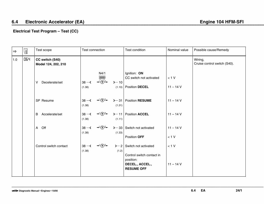
6.4 Electronic Accelerator (EA) Engine 104 HFM-SFI ––––––––––––––––––––––––––––––––––––––––––––––––––––––––––––––––––––––––––––––––––––––––––––––––––––Electrical Test Program – Test (CC)
O A Test scope Test connection Test condition Nominal value Possible cause/Remedy
1.0 064 CC switch (S40)Model 124, 202, 210
V Decelerate/set
SP Resume
B Accelerate/set
A Off
Control switch contact
38 w(1.38)
38 w(1.38)
38 w(1.38)
38 w(1.38)
38 w(1.38)
N4/1E
c
c
c
c
c
L 10(1.10)
L 31(1.31)
L 11(1.11)
L 33(1.33)
L 2(1.2)
Ignition: ONCC switch not activated
Position DECEL
Position RESUME
Position ACCEL
Switch not activated
Position OFF
Switch not activated
Control switch contact inposition:DECEL., ACCEL.,RESUME OFF
< 1 V
11 – 14 V
11 – 14 V
11 – 14 V
11 – 14 V
< 1 V
< 1 V
11 – 14 V
Wiring,Cruise control switch (S40).
–––––––––––––––––––––––––––––––––––––––––––––––––––––––––––––––––––––––––––––––––––––––––––––––––––––––––––––––––––––––––––––––––––––––––––––––––––––––––––––––––––––––––––––––––––––––––––––––––––––––
b Diagnostic Manual • Engines • 10/00 6.4 EA 24/1

6.4 Electronic Accelerator (EA) Engine 104 HFM-SFI ––––––––––––––––––––––––––––––––––––––––––––––––––––––––––––––––––––––––––––––––––––––––––––––––––––
Electrical Test Program – Test (CC)
O A Test scope Test connection Test condition Nominal value Possible cause/Remedy
[1.0] 064 Models 129, 140
V Decelerate/set
SP Resume
B Accelerate/set
A Off
Control switch contact
79 w(1.38)
79 w(1.38)
79 w(1.38)
79 w(1.38)
79 w(1.38)
N4/1E
c
c
c
c
c
L 51(1.10)
L 72(1.31)
L 52(1.11)
L 74(1.33)
L 43(1.2)
Ignition: ONCC switch not activated
Position DECEL
Position RESUME
Position ACCEL
Switch not activated
Position OFF
Switch not activated
Control switch contact inposition:DECEL., ACCEL.,RESUME, OFF
< 1 V
11 – 14 V
11 – 14 V
11 – 14 V
11 – 14 V
< 1 V
< 1 V
11 – 14 V
–––––––––––––––––––––––––––––––––––––––––––––––––––––––––––––––––––––––––––––––––––––––––––––––––––––––––––––––––––––––––––––––––––––––––––––––––––––––––––––––––––––––––––––––––––––––––––––––––––––––
b Diagnostic Manual • Engines • 10/00 6.4 EA 24/2

6.4 Electronic Accelerator (EA) Engine 104 HFM-SFI ––––––––––––––––––––––––––––––––––––––––––––––––––––––––––––––––––––––––––––––––––––––––––––––––––––
Electrical Test Program – Test (CC)
O A Test scope Test connection Test condition Nominal value Possible cause/Remedy
2.0 080 Stop lamp switch (S9/1)Signal (N.O. contact)Model 124, 202, 210
Model 129, 140
Signal (N.C. contact)Model 124, 202, 210
Model 129, 140
38 w(1.38)
79 w(1.38)
38 w(1.38)
79 w(1.38)
N4/1E
c
N4/1E
c
N4/1E
c
N4/1E
c
L 30(1.30)
L 71(1.30)
L 13(1.13)
L 54(1.13)
Ignition: ONBrake pedal not applied
Brake pedal applied
Ignition: ONBrake pedal not applied
Brake pedal applied
<1 V
11 – 14 V
11 – 14 V
<1 V
Wiring,Stop lamp switch (S9/1).
–––––––––––––––––––––––––––––––––––––––––––––––––––––––––––––––––––––––––––––––––––––––––––––––––––––––––––––––––––––––––––––––––––––––––––––––––––––––––––––––––––––––––––––––––––––––––––––––––––––––
b Diagnostic Manual • Engines • 10/00 6.4 EA 24/3

6.4 Electronic Accelerator (EA) Engine 104 HFM-SFI ––––––––––––––––––––––––––––––––––––––––––––––––––––––––––––––––––––––––––––––––––––––––––––––––––––
Electrical Test Program – Test (CC)
O A Test scope Test connection Test condition Nominal value Possible cause/Remedy
3.0 096 Starter lock-out/backuplamp switch (S16/1)Selector lever positionrecognitionModel 124, 202, 210
Model 129, 140
4 w(1.4)
38 w(1.38)
4 w(1.4)
38 w(1.38)
N4/1E
c
N4/1E
c
N4/1E
c
N4/1E
c
L 35(1.35)
L 29(1.29)
L 35(1.35)
L 29(1.29)
Ignition: ONTransmission range: P/N
R/D/3/2
Ignition: ONTransmission range: R
P/N/D/3/2
Ignition: ONTransmission range: P/N
R/D/3/2
Ignition: ONTransmission range: R
P/N/D/3/2
11 – 14 V< 1 V
11 – 14 V< 1 V
11 – 14 V< 1 V
11 – 14 V< 1 V
Wiring,Starter lock-out/backup lampswitch (S16/1).
–––––––––––––––––––––––––––––––––––––––––––––––––––––––––––––––––––––––––––––––––––––––––––––––––––––––––––––––––––––––––––––––––––––––––––––––––––––––––––––––––––––––––––––––––––––––––––––––––––––––
b Diagnostic Manual • Engines • 10/00 6.4 EA 24/4

6.4 Electronic Accelerator (EA) Engine 104 HFM-SFI ––––––––––––––––––––––––––––––––––––––––––––––––––––––––––––––––––––––––––––––––––––––––––––––––––––
Electrical Test Program – Test (CC)
O A Test scope Test connection Test condition Nominal value Possible cause/Remedy
4.0 I28
I29
I30
Left front axle VSS sensor (L6/1)Speed signalModel 124, 202, 210
Model 129, 140
38 w(1.38)
79 w(1.38)
N4/1E
f
N4/1E
f
L 15(1.15)
L 56(1.15)
Lift front of vehicle:
Ignition: ONTurn left front wheel byhand.
Note:Upon completion of test,erase DTC’s from ASRcontrol module memory
> 3 V
> 3 V
Wiring,Left front axle VSS sensor (L6/1),DM, Chassis & Drivetrain, Vol. 1,section 5.
5.0 II2
II5
II7
CAN data busModel 124, 202, 210
Model 129, 140
20 w(1.20)
“L“ w
N4/1E
b
N4/1x1b
L 21(1.21)
L “H“
Ignition: OFF
Ignition: OFFRemove contact module.
Measure resistance atconnector for controlmodule N4/1.
55 – 65 ]
115 – 125 ]
Wiring,Engine control module (N3/4),EA/CC/ISC control module (N4/1).
–––––––––––––––––––––––––––––––––––––––––––––––––––––––––––––––––––––––––––––––––––––––––––––––––––––––––––––––––––––––––––––––––––––––––––––––––––––––––––––––––––––––––––––––––––––––––––––––––––––––
b Diagnostic Manual • Engines • 10/00 6.4 EA 24/5